FS 150 - Elektro-Trading sp. z oo
FS 150 - Elektro-Trading sp. z oo
FS 150 - Elektro-Trading sp. z oo
- No tags were found...

You also want an ePaper? Increase the reach of your titles
YUMPU automatically turns print PDFs into web optimized ePapers that Google loves.
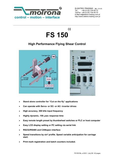
control – motion – interfaceELEKTRO-TRADING <strong>sp</strong>. z o.oTel. +48 (0-32) 734-55-72Tel/Fax +48 (0-32) 734-55-70E-Mail et@elektro-trading.com.plhttp://www.elektro-trading.com.pl<strong>FS</strong> <strong>150</strong>High Performance Flying Shear Control• Stand alone controller for “Cut on the fly“ applications• Can operate with Servo- or DC- or AC- inverter drives• High accuracy, 300 kHz input frequency• Highly dynamic, <strong>150</strong> μsec re<strong>sp</strong>onse time• Easy remote length preset by thumbwheel switches or PLC or host computer• Easy LCD di<strong>sp</strong>lay setting or PC setting via serial link• RS232/RS485 and CANopen interface• Speed transitions by sin² profile. Speed variable anticipation for carriagestart.• Print mark registration and batch counters included.<strong>FS</strong><strong>150</strong>16b_e.DOC / July 08 / 42 pages
Important Notice:Versions <strong>FS</strong> <strong>150</strong>14A and higher use some different control inputs and outputs andtherefore are not fully hardware compatible to former versions!You must modify a few connections at the PI/PO connector when replacing older versionagainst <strong>FS</strong> <strong>150</strong>14A or a higher version! See section 5.The software has been upgraded and now includes• Batch counters for total quantity, waste quantity, total length• Registers for actual line <strong>sp</strong>eed, carriage <strong>sp</strong>eed, synchronising error etc.• 3 software limit switches to protect against carriage oversh<strong>oo</strong>t. No more proximities forextreme carriage positions necessary.• Real acceleration settings instead of ramp times• Virtual master axis with adjustable simulation <strong>sp</strong>eed• Impulse output with scaling facility for material line• Correction register for easy compensation of slip of the measuring wheel• Enhanced setup t<strong>oo</strong>ls in the OS30 operator software, including scope functions, providingstill easier commissioning procedures.• Improved S- shape profile for still higher cutting efficiency.1. IntroductionFlying shears are used for cutting applications, where endless material to be cut to lengthcannot be stopped during the cutting process and the cut must be effected “on the fly“. Themechanical construction provides a saw or shear system mounted on a carriage, that followsthe material with synchroneous <strong>sp</strong>eed while cutting is in progress, and then returns to a homeposition to wait for the next cut. See schematics on title page.The <strong>FS</strong> flying shear control is based on a BY <strong>150</strong> synchroniser system. The software has beendesigned for the <strong>sp</strong>ecial requirements of flying shears under consideration of maximumefficiency and accuracy at minimum stress for all mechanical parts.Only a few registers must be set in order to adapt the controller to the mechanical and electrical<strong>sp</strong>ecifications of the shear system.A small keypad with LCD provides easy setup, but also a disc with operator software OS30 isincluded for easy PC setup of the controller.All essential registers like cutting length, t<strong>oo</strong>l width etc. are also accessible by parallel interface,providing easy setting by remote BCD thumbwheel switch or PLC parallel output.The unit uses a closed 19“ steel cassette for maximum EMC protection. With option SM<strong>150</strong>, thehousing can also be mounted on DIN rails.3
2. Principle of OperationThe shear (or saw blade) is fixed on a carriage that can move forward and reverse undercontrol of a +/- 10V <strong>sp</strong>eed reference voltage of the carriage drive. Normally, a 4 quadrant DC orservo drive is used. For lower requirements in performance, the <strong>FS</strong><strong>150</strong> unit can also control 1-quadrant AC drives using a positive <strong>sp</strong>eed reference signal and two outputs for forward/reverseselect.The <strong>FS</strong> <strong>150</strong> controller counts the length from the line encoder (feed roll or measuring wheel)while the carriage is held in its rear home position.Once the cutting position approaches, the carriage accelerates and synchronises with the line.A "Ready to cut" signal is generated in order to start the cutting process, while the shear movesfully synchroneous with the cutting position on the material. When the cut is completed, the<strong>FS</strong> <strong>150</strong> must receive a "cut complete" signal. This will cause a deceleration and a reversal ofthe carriage until it has reached it's home position again. All <strong>sp</strong>eed transitions occur with asm<strong>oo</strong>th sin² <strong>sp</strong>eed profile for absolutely careful treatment of screws and other mechanical<strong>sp</strong>arts.VLVCutLine <strong>sp</strong>eedtSpeed profileFig 1The <strong>FS</strong> <strong>150</strong> control continuously measures the line <strong>sp</strong>eed and calculates an anticipation valueto start the carriage before the cutting length is reached. Thus the shear will exactly match thecutting position of the material upon completion of the acceleration ramp and no overswing oroscillation will take place prior to the cut. This saves time and increases the cutting efficiency ofthe shear system considerably.3. Hardware ConfigurationAs a master drive, mostly the motor of a feed roll is used. The "master" can also be a measuringwheel equipped with an incremental encoder. The encoder resolution should be at least 5times higher than the maximum acceptable cutting error.Quadrature encoders (TTL-types A, A, B, B) must be used. Where you find you must use 24Vencoders with A/B output, please apply our level converter type PU202 to generate the properRS422 signals required.Digital feed forward technology needs a certain minimum frequency: At maximum line <strong>sp</strong>eed,the master encoder frequency should be at least a few hundred Hertz. It is best to ch<strong>oo</strong>se theppr numbers of line and carriage encoders in a way to produce frequencies in the same range.It is necessary to adjust the slave to it's maximum dynamic re<strong>sp</strong>onse (no internal ramps, nointegral control l<strong>oo</strong>p, high proportional gain etc.) because the <strong>FS</strong> <strong>150</strong> will generate ramps towhich the drive must follow with no additional delay..A signal must be available to indicate completion of a cut to the <strong>FS</strong> <strong>150</strong> controller. All controlsignals must be PNP (switching to positive) with a level of 18....30 volts DC. Fig. 2 shows theblock diagram of the unit.4
Measuring wheelCarriage EncoderCarriage driveLineEncoder*)+/-10V (or +10V)Power24VDCRS232RS485CANMaster InputA, A, B, BCommunicationPortsSlave Input Analogue OutputA, A, B, B<strong>FS</strong><strong>150</strong>Bold printed connectionsare "must"Other connections Outputsare "can"ReadyReverseForwardlengthCarriage AlarmHome positionGap compl.Ready to cutControl InputsParallel Data InputResetJog forw.Jog rev.Read PIStart GapCut CompletedStore EEpromStart/StopImmediate CutLength1/ Length2Zero PositionDec CounterVirtual line OnPLC orBCD switch*) With 1 Q drives onlyFig. 2For safety reasons, we strictly recommend to limit the travelling range by mechanicallimit switches at both ends in order to avoid damage with carriage oversh<strong>oo</strong>t uponfailure of the electronic control system!4. Wiring and ScreeningSerial RS232(Sub-D-9- female)LEDbargraphMaster ResetbuttonCAN Bus24VDCSupplyParallel Interface(Sub-D-25- male)Control IN/Out(Sub-D-25- female)Analogue Out(Sub-D-9- female)PE (Grounding screw)Carriage encoder(Sub-D-9- male)Line encoder(Sub-D-9- male)Fig.35
For reasons of proper screening, it is a must to follow the subsequent instructions.Where you don’t exactly observe these grounding and screening rules, it is almost forsure that you will have problems later!a. The minus wire of the power supply must be connected to the grounding screw on the frontplate of the <strong>FS</strong><strong>150</strong> controller with a short wire of at least 0.75 mm².On site of the power supply, the minus output must be earthed.Where the wires between power unit and <strong>FS</strong><strong>150</strong> controllers are longer than e.g. 1 meter, it isadvisable to ground the front plate of the controller again by a separate wire, on the shortestway possible.+24V<strong>FS</strong><strong>150</strong>Power SupplyPESupplement short earthing when power cable is longFig.4b. All screens on the controller side must be connected to the housing of the corre<strong>sp</strong>ondingSub-D-connector. This is valid for encoder cables, analogue output and PI or PO lines.Where you use Sub-D-connectors with a plastic housing, you must solder the screen to themetallic frame of the connector. At any time you must be sure the screen gets a propercontact to the front facia of the unit when connected to the controller.Screenc. When encoder cables are interrupted by terminal boxes or intermediate connectors on theirway from the controller to the encoder, you must connect the screen to the Minus wire of theencoder supply there, but never to earth potential again!!.Fig.5Encoder cableto encoderto <strong>FS</strong><strong>150</strong>Minus of encoder supplyScreenTie Minus of encoder supply and screen together whereeveryou interrupt the encoder cable by terminal or connectors.Make sure the screen can never get any earth potential here!Fig.66
d. When the cable arrives at the encoder site, the screen must again be connected to theMinus wire of the encoder supply, but not at all grounded to earth. In general, there are twotypes of encoder connections:Encoder with plug connectorShaftEncoderMake sure the screen of the cable is connectedto the Minus supply of the encoder, but does nottouch the metallic housing of the connector.Fig.7Encoder with cable endShaftEncoderFrom <strong>FS</strong><strong>150</strong>Leave this screen fully unconnectedhere to avoid illegal double-earthing!(Screen is internally earthed tothe encoder housing.)Connect screen to the Minus wire of theencoder supply here. Avoid any earthconnection via contact to housings ect.Fig.8e. With all other cables like analogue output, control or parallel output, put the screen to themetal connector housing on the <strong>FS</strong><strong>150</strong> side and leave it unconnected on its peripheralside. Again avoid double earthing. The only place where the screen is earthed must be thefront plate of the unit!Example : Analogue <strong>sp</strong>eed reference signalDriveSpeedRef.to <strong>FS</strong><strong>150</strong>This screen unconnectedand not earthed!This screen to metal frame of Sub-D-ConnectorFig.94.1 EncodersAll cables connected to the <strong>FS</strong><strong>150</strong> should be separated from motor cables and otherpower lines. It is indi<strong>sp</strong>ensable to use screened motor cables.The unit only accepts TTL impulse signals ( 5V, RS 422 ) or similar from an encoder simulation(resolver). It is essential to connect the channels A, A,B,B: The index inputs Z and Z are notused with this application.Where you find you are working with existing 10 - 30 Volt encoder signals which feature onlyA/B signals, the PU 202 converter should be used to gain full complementary signals in line withRS 422 standards.7
An auxiliary voltage of 5,5 V ( max. 500 mA ) is available on the connector plugs “Master“ and“Slave“, for easy supply of the encoders. Both connectors on the unit are Sub - D - 9 pin, male.Fig. 4 and Fig. 5 show the encoder connections and the principle of the input circuit. All impulseinputs are isolated by high <strong>sp</strong>eed optocouplers.When connecting the encoders it is not t<strong>oo</strong> important to wire the A and B signals to produce thecorrect counting direction. The direction can be determined in the setup menu.+5VDCVcc int.B A A B A A0VDCGND int.1 2 3 4 56 7 8 91 2 3 4 56 7 8 9 GNDZ Z B Z Z BMasterSlaveDIL-Switches 1-4 have no function.(different from previous hardware versions)Fig.104AInput ciruit (principle)220Opto+ 5VDCDCVCC int.A220- 0VDCGND int.Opto5 GNDInput currents approx. 10mAFig.11Important• With encoders, supplied by the <strong>FS</strong> <strong>150</strong>:Connector pins 4 and 5 provide the encoder supply.• With encoders, supplied by an external source, or when an encoder simulationfrom the drive is used (Common GND operation)Use connector pin 5 as common zero Volt potential.• For fully potential-free operation:Connect only A, A and B, B and leave terminal 5 ( Common ) unconnected.For reason of best noise immunity, we recommend to use potential- free operationwherever you have line driver signals with remote supply.8
Warnings:• You must ensure that no external voltage is applied to pins 4 and 5 as this can causeserious damage to the unit!• Where you use one common encoder for feedback of the drive and feedback for the <strong>FS</strong><strong>150</strong>at the same time, there may come up interference problems. You can use a GV<strong>150</strong>impulse <strong>sp</strong>litter to eliminate any kind of problems. In most applications, the commonencoder would also work fine when it is supplied by the drive and the <strong>FS</strong><strong>150</strong> operates infully differential mode like shown.Encoder+AABBDriveScreen4 (NC)9<strong>FS</strong><strong>150</strong>12 Dil 3 and3 Dil 4 OFF5 (NC)Fig.12DIL switches S1 / 5 - 8 provide the selection of the encoder edge counting. It is possible withcomplementary signals to count with times 1, 2, or 4 without any fear of miscounting. Theselection always applies separately to the master and the slave input signals.Please note, thatMaster:DIL-Pos. 5 DIL-Pos. 6 edge countONOFFONOFFONONOFFOFFx1x2x4counter disabledSlave:DIL-Pos. 7 DIL-Pos. 8 edge countONONx1OFFONOFFONOFFOFFx2x4counter disabled• the maximum frequency of the <strong>FS</strong><strong>150</strong> refers to the total number of edges counted, i.e.300 kHz ( x1 ) or <strong>150</strong> kHz ( x2 ) or 75 kHz ( x4 ).• impulse numbers, to be entered upon setup, also refer to the total number of edgescounted, i. e. the entry data must be doubled with ( x2 ) etc.• When possible, you should set the switches in a way to produce approximately similarimpulse numbers on Master and Slave side to achieve best operation. i.e. 4096 impulses x1 on the Masterside and 1000 impulses x 4 on the Slave side. The cross section ofencoder cables must be chosen with consideration of voltage drop on the line. The <strong>FS</strong><strong>150</strong>provides a 5.5 V encoder supply and at the other end the encoder must at least receive it`sminimum supply voltage! (See encoder <strong>sp</strong>ecifications).9
4.2 Analogue OutputThe analoge connector (Sub-D-9 female) provides several auxiliary lines that are not applicablewith <strong>FS</strong><strong>150</strong> functions. The only pins that must be connected are pin 2 (GND) and pin 7 (output).The cable must be screened and the screen must be connected to the connector housing onthe <strong>FS</strong><strong>150</strong> side. The screen must be unconnected on the drive side!Summ .in- +(internally connected)5 4 3 2 19 8 7 6GNDOut2 LVinKorr LVoutAnalogue ConnectorFig. 134.3 Power SupplyThe <strong>FS</strong> <strong>150</strong> operates from an unstabilised 24 VDC supply (+/- 25%), however, the voltageincluding ripple should not exceed the following limits (18 V...30 V). The supply of the <strong>FS</strong> <strong>150</strong> isboth electrically and mechanically protected against wrong polarity misconnection by protectiondiodes and a <strong>sp</strong>ecial plug.Warning:At pin 1 of the "PI" connector and pin 1 of the "PI/PO" connector, a polarity protected + 24 Vsupply is available for various purposes. Keep these lines strictly separated from the + 24 Vpower supply.When these lines come together, the electrical polarity protection would be bypassedand any incorrect polarity on the unit`s power input would cause definite andirrecoverable damage!24 voltsDC supply+Polarityprotecion+2200 uFPI Pin 1PI/PO Pin 124 volts out(switches andoutput)-GNDFig. 144.4 Parallel InterfaceThe interface provides remote setting of operational and configuration registers. It receives BCDor binary data (selectable) from a remote thumbwheel switch or PLC control. There are therebinary coded select lines which provide 8 addresses being accessible, via 20 data lines. Theregister parameters are stored in the following manner:10
a. Read and activate parallel data upon a strobe pulse. The data is then transmitted to theinternal RAM and activated immediately.b. Store the data to the EEprom by a Store pulse, when you like the unit to use same dataagain after power down.It is easy to see how 8 external registers may be loaded into the BY <strong>150</strong>. For operation of Readand Store inputs see section 4.5.The connection of the parallel interface is a 25 pin Sub-D connector (male) which is marked as"PI" on the front facia.All inputs are PNP switching and fully PLC compatible. All signals refer to GND and theminus potential of the supply.Logic 0Logic 1( low )( high )==0.....818...30VoltsVoltsImportant AdviceUpon power up, the unit loads the full register set stored in its EEProm. Data transmitted fromthe parallel and/or serial interface will overwrite the operational RAM data, but not the corre<strong>sp</strong>ondingEEProm registers. As a result, when powering up, any parallel or serial data will bereplaced by EEProm data, until it is overwritten again.The RAM data however can be restored to the EEProm at any time by parallel or serialcommand.Parallel interface operations must keep the following timing conditions:Data validBCD DATARead impulseT1T2T1 min. = 5 msec.T2 min. = 5 msec.Fig. 15Data latch occurs with the positive transition of the strobe pulse. Data lines must be in a validstate at least 5 msec prior to the strobe, and remain present for an additional 5 msec while thedata is read. There is no upper limit for T1 and T2.Mostly the parallel interface is used to preset the cutting length by a simple remote BCDthumbwheel switch or by a PLC parallel output. The select lines S1-S3 allow to preset als<strong>oo</strong>ther registers like shown in table above. Registers are described later in this manual.Pin 3 of the PI parallel interface provides a <strong>sp</strong>ecial control function:A “virtual line axis“ can be switched on by this pin, allowing to fully operate all carriagefunctions without material and with the measuring wheel in standstill. This is useful for testingand commissioning. More details are to be found in the section “Virt. Line“.11
11421531641751861972082192210231124122513+ 24V outS1SelectS2LinesS3VIRTUAL LINE ONBCD1Low orderBCD2digitBCD4(LSD)BCD8BCD1BCD2MSD -3BCD4BCD8BCD1BCD2MSD -2BCD4BCD8BCD1BCD2MSD -1BCD4BCD8BCD1High orderBCD2digitBCD4(MSD)BCD8S3 S2 S10 0 00 0 10 1 00 1 11 0 01 0 11 1 0Length 1 (C02)Length 2 (C03)+/- Sync (C06)Accel 1 (C04)Accel 2 (C05)Sync Time (C07)Virt Line (C19)See register descriptionWith signed parameters the mostsignificant bit (pin 13) is used assign bit (low = +).When using binary format pin 16is the LSB and pin 13 is the MSB.Fig. 165. Control IN / OUT Port (PI/PO)There are 12 input lines and 8 output lines for remote control purpose.13251224112310229218207196185174163152141ResetJog forwardJog reverseRead and activate PSS dataStart gapCut completedStore data to EEPromStart / StopImmediate cutLength select / print markSet zero positionDecrement batch counterGNDGNDCOM+OptoCOM+ReadyReverseForwardLength outCarriage position alarmHome positionGap completeReady to cut+24V outInputs15 K2,7 KCom+10-30V33 ROutmax. 70 mAOutputsLow = 0.. . 8VHigh = 18.. 30VFig. 1712
Inputs:Reset (13):When set High, a new initialising cycle is started and error messages will be cleared. Resetdoes not affect any carriage position counters or batch counters.Jog forward (25) / Jog reverse (12):Moves the carriage in one or the other direction (Jog <strong>sp</strong>eed registersettable). The carriage automatically stops when it reaches one of the software limit switches(Minimum or Maximum position). Jog inputs are only active when the Start/Stop input is in stopstate. The software limit switches do not operate while you keep the “Teach Zero“ input high.Whenever the Jog command is released, the shear will be electrically hold in it's new actualposition and start from there to execute the next cut.Read and activate data (24):Reads data from the parallel interface and activates new data in the cutting process.Start gap (11):Upon completion of the cut it is possible to shortly accelerate the carriage, so the t<strong>oo</strong>l will shiftforward the material and make a gap between. The size of the gap is register settable and anoutput will signal when the gap is completed. Leave input unconnected when gap function notused.Cut completed (23):This input must receive a signal when a cut has been completed. The direction of the signal(High/Low) is register selectable. With the selected edge the <strong>FS</strong> <strong>150</strong> will start deceleration andreversal in order to put the carriage back to it's rear home position. Each cut completed signalwill increment the batch counter.Store EEprom (10):A High signal on this input will store all register data to the EEprom. Data which have beentransmitted by the parallel interface will be lost after power down, unless this input has beenactivated prior to power down. The EEprom has a limited number of 100.000 store cycles duringit’s life time.Start / Stop (22):When low, the automatic cutting cycle will be interrupted, but the Jog functions and theImmediate cut input will remain active. When high, the carriage will continously execute cuttingcycles according to the preset length.Immediate cut (9):A positive edge at this input will immediately start the shear for a cutting cycle, independant onwhat the actual length is. The subse-quent cut will corre<strong>sp</strong>ond to the preset length again, unlessa Flying Cut has been triggered again.This function i.e. allows the operator to cut out bad parts of the material. Immediate cutcommands will increment the waste counter.Length select / print mark:This input provides a double function:With Mode 1 (normal operation without print mark), this is a length selection. Since the unitstores two cutting lengths (Length 1 and Length 2), a low at this input selects Length 1 to be cutwhile a High at this input selects Length 2.With Mode 2 (operation with print marks), this is the input for the sensor or photocell detectingthe print mark.13
Set Zero position (8):This input allows to define the “Zero“ position of the carriage. The internal carriage position counteris Reset to Zero while this input is High. All limitation settings and alarms refer to this zero position.Please note that upon power up the carriage position counter will be cleared also, and the unitwould take any actual position as a Zero position. Where you power the controller down while thecarriage is not in at Zero, or where you move the carriage with the controller in powerless state, it isalways necessary to redefine “Zero“ after power up by a positive signal to this input.Decrement batch counter (20):The unit provides an internal batch counter incrementing by one with each cut. If for any reasonone cutted piece cannot be used (waste), the counter can be decremented by a positive edge tothis input, to match the real number of usable products.Outputs:Ready (5):A high signal indicates the unit is ready to operate and a low signal indicates the unit is out oforder or an error has been detected and the unit has switched off the control l<strong>oo</strong>p (see “Errors“).When high, the unit could not detect a fault by itself, but this is not a guarantee that the wholesystem is ready to work.Reverse (17) / Forward (4):Where you use a carriage drive with only positive <strong>sp</strong>eed reference and digital forward/reverseselect, these two outputs will control the direction of rotation. The output goes High when thecorre<strong>sp</strong>onding direction is required.Length out (16) :This output generates impulses proportional to the line motion with scalable length units. As anexample, it might be used to totalise full meters of material passing through, by a separatecounter or PLC.Carriage position alarm (3):This can be used to limit the travelling way of the carriage into forward direction duringproduction.If, i.e., for mechanical or other reason, the carriage could not synchronise with the line, thecontroller would never generate the „“Ready to cut“ signal and the carriage would run to thefront detent. The alarm position is register settable and this output switches High to indicate thecarriage will run out of range if not breaked down immediately.Carriage home (15):A high state of this output indicates the carriage is in it’s home position like defined by register“home window“.Gap complete (2) :When the gap function is used, a high signal indicates that the gap has been executed and thecontroller now waits for the “cut completed“ input.Ready to Cut:This output goes High when the shear has reached it's cutting position with re<strong>sp</strong>ect to thematerial and moves fully synchroneous with the line. See parameter "Cut window". It goes Lowagain when the shear signals "Cut completed".14
Important remarks:1.When for any electrical or mechanical reasons the carriage cannot reach the proper cuttingposition or cannot synchronise with the line <strong>sp</strong>eed, the "Ready to Cut" signal will neverswitch on and the carriage could run to it's front detent without executing a cut! Use theCarriage alarm output and mechanical safety switches to avoid damage.2. Each cut must be followed by a "Cut completed" signal, otherwise no reversal of the carriagewill take place and it will run to it's front detent! For tests (with saw blade or shear removed)it is legal to connect the “Ready to cut“ output to the “Cut completed“ input.6. The Serial PortThe RS 232 serial link can be used for two purposes:The unit includes a serial RS232 and a RS485 interface, both accessible by the Sub-D-9connector marked „RS232“.RS 232GND TxDext. RxDGNDint.549382716Serial interfaceconnector+5V T+ T- R+ R-RS 485Fig.18To run the OS 3.0 operator software with your PC by RS232, your PC must be connected to the<strong>FS</strong><strong>150</strong> unit like shown:PC235RxDTxDGNDRxDTxD235<strong>FS</strong><strong>150</strong>Sub-D-9- femaleSub-D-9- maleOnly pins 2, 3 and 5 must be wired and pins 2 and 3 must be crossedFig.19Please make sure your PC serial cable uses only the three pins shown. When also other pinsare connected, this will cause interference with the RS485 pins and the PC communication willnot work.When using the RS485 interface, you can serve up to 32 different bus participants in either 2-wire or 4-wire transmissions mode. The subsequent figures show, as an example, how to run aTX720 operator terminal with a <strong>FS</strong><strong>150</strong> unit and other controllers.15
Shield2 x120 Ohms2 x120 OhmsT+ T- R+ R-R+ R- T+ T-8 7 6 16 1 8 7R+ R- T+ T-TX720 <strong>FS</strong><strong>150</strong> Other deviceRS485 (4-wire system)Fig.20T+Shield120 OhmsT-120 Ohms8 7TX7208 7<strong>FS</strong><strong>150</strong>other deviceRS485 (2-wire system)Fig.21A detailed description of the serial protocol is available upon request or can be downloadedfrom the Download site of the motrona homepage (www.motrona.com, document name:„Serpro“).7. Register settingsRegisters can be set by keypad under LCD control or by PC, using the OS30 operator software.This section describes the registers and their meanings and the next section shows how toprogram the registers.The unit provides 4 Sub-Menus.Data InSetupAdjustTest progContains operational registers.Contais registers that need to be set only once upon commissioning.provides easy setting of the analogue gains upon commissioning.executes various testing functions for internal and external signals.Expressions like C00 indicate the serial register access codes.16
BAData In Set - up Adjust Testprog2P CBAC00C01C02C03C04C05C06C07C08C09C10C11C12C13C14C15C16C17C18C19C20C21C22C23C24C25C26C27C28C29C30Pulses Line/1000Pulses Cut/1000Length 1Length 2Acceleration 1Acceleration 2+/- Synchron RateSynchron TimeT<strong>oo</strong>l WidthIntegration TimeCut WindowGap LengthGap TimeEdge SenseJog SpeedJog RampHome WindowMinimum PositionMaximum PositionVirtual Line SpeedPhoto -> CutDead BandReturn WindowReturn SpeedSampling TimeAlarm PresetLength / PulseScaling LengthPower SenseRamp FormSync SamplesC40C41C42C43C90C91C92C93C94C95C96C97C45C46C47C48C49C50Mode1Q/4QPI-FormatAdd-CorrectionUnit-NumberBaud- RateSerial FormatBus-AddBus-BaudBus-ConfigBusTxParBusRxParMaster DirectionSlave DirectionOffset CorrectionGain CorrectionOffset TotalGain TotalGain - CorGain - TotMast-DirSlav-DirOffs-CorGain-CorOffs-TotGain-TotLed + POCont. inPI inInd-MastInd-SlavDAC-CorDAC-TotFactoryPCBAFig.2Prior to register setting you must decide with which dimensions or units you like to preset thecutting length. This could be 0.1mm or 1mm or 0.001 inch or any other resulution you desire. Allfurther settings refer to the length units you decided to use. When i. e. you ch<strong>oo</strong>sed to set thelength with a resolution of 0.1mm, 1000 length units will be 100 millimeters and you must presetthe length in a format like 100.0mm.Pulses Line:This register calibrates the encoder ppr of the line encoder. You must find out how manyimpulses we receive when the line moves 1000 length units forward. Set the number ofimpulses to this register.Range 0-999 999Pulses Cut:This register calibrates the encoder ppr of the carriage encoder. Setting is similar to the Pulselines register.Length 1 / Length 2:These registers contain your cutting lengths. Enter a default length here.17
Clarification: You can preset two length and the remote signal “Length select“ will decidewhether we cut length 1 or length 2. Upon power up, the unit will load the length set to theseregisters. Data transmitted by parallel or serial interface will overwrite the registers. Parallel orserial data will be valid until to the next power down only, unless they have been stored by a“Store to EEprom“ command.Acceleration 1: Acc/Dec rate for forward motion of the carriage, scaled in length units/sec².Acceleration 2: Acc/Dec rate for reverse motion of the carriage, scaled in length units/sec².Remarks to acceleration settings• The ramp times for acceleration and deceleration result from the setting and from the<strong>sp</strong>eed. Where you use length units of entire millimeters and you set Acceleration to10 000 mm/sec², the unit would accelerate the carriage within one second from standstill to10 m/sec which is 600 m/min. This means it would take 100 msec to go from standstill to60 m/min etc.• Acceleration values must be set in a way that motor and drive can follow the rampsgenerated by the controller. Setting values outside the physical range of the drive systemresult in malfunction or failure of the whole system.SpeedCutAcc 1 Acc1Sync <strong>sp</strong>eedTimeAcc2Acc2Fig.23+/- Synchron Rate:This register allows to slightly vary the synchronous <strong>sp</strong>eed in a range of +/-9.99%. In general,this register will be set to 0.00 and the carriage will synchronise with the line exactly accordingto the encoder information.Some applications with extrusion lines need to adapt the sync <strong>sp</strong>eed, because the material ishot and c<strong>oo</strong>ls down on the way between the measuring wheel and the cutting position. This willcause shrink which can be compensated by the +/- Synchron Rate register. It affects thesynchronous <strong>sp</strong>eed but not the length.Synchron Time:This is an adjustable delay time between reaching the synchronous <strong>sp</strong>eed and switching on the“Ready to cut“ output. Setting range 1-9999 milliseconds. Under regular conditions the carriagewill be in the correct cutting position immediately after completation of the acceleration rampand the Sync Time register can be set to it’s minimum value of 1 msec. With mechanicallyunstable carriage con-structions it may however be applicable to leave a short stabilisation timebefore activating the cut.18
SpeedSyncTimeSync <strong>sp</strong>eedReady to cut outputFig.24T<strong>oo</strong>l width:Provides compensation of the width of the saw blade or cutting t<strong>oo</strong>l. Setting 0-999 length units.Integration Time :Sets the integration in order to avoid cutting errors caused by non-linearities of the carriagedrive.00 = Integrator off01 = Fast integration99 = Slow integrationFor setting see section “Steps for commissioning“.Cut Window:Sets a tolerance window around the cutting position where the carriage must be before the“Ready to cut“ signal is switched on. Setting is directly in number of increments of the carriageencoder. Range 1-99 increments. We recommend to set this window not t<strong>oo</strong> small, because nocut will be activated when for any reasons we do not reach this window (carriage will run to thefront limit).Gap Length:In some applications it is desirable, after the cut, to shortly acceler-ate the saw blade in order toshift the cutted piece forward and produce a gap prior to removing the t<strong>oo</strong>l from the line. Thegap can be set directly in length units, range 0-9999. In most applications, this function willnot be used. To use the gap function, the following timing of signals must be observed:GapTimeSpeed overh<strong>oo</strong>t to make gapLine <strong>sp</strong>eedOutput"Ready to cut"External Input"Make gap"Output"Gap Complete"External Input"Cut completed"Fig.25When the gap function is not used, the input “Make gap“ remains unconnected, but at any timethe signal “Cut completed“ must be applied to start the return process of the shear.19
Gap Time:Time in milliseconds to make the gap. Range 1 - 9999 msec.Edge sense:Sets the active edge for the external “Cut completed“ signa0 :LOWHIGHRising edge at input "Cut completed"terminates the synchroneous phaseand starts the return cycle1 : HIGHLOWFalling edge at input "Cut completed"terminates the synchroneous phaseand starts the return cycleFig.26Jog <strong>sp</strong>eed:Sets the carriage <strong>sp</strong>eed when one of the “Jog forward“ or “Jog reverse“ inputs is active. Thesetting range is 0.00 to 9.99 Volts of <strong>sp</strong>eed reference for the slave drive.Jog Ramp:Ramp time for Jog operation, dependant on selected jog voltage:0000:(jump)0030:(approx. 100 msec/Volt)0060etc.:(approx. 200 msec/Volt)Fig.27Home Window:Sets a window around the home position of the carriage. Setting in length units 1-9999 units.The output “Carriage home“ is high when the carriage position is inside this window. The unitwill go to Alarm state when a new cutting cycle will be started before the carriage has returnedto the home window from the previous cut.Min Position Max Position:Programmable software limit switches for the extreme forward and rear carriage position.Setting is in length units and the range is from -999999 to + 999999. The setting refer to the“Zero“ Position which is set by the “Zero Position“ input. In general (but this is not a “must“), theZero position is also used as the “Home“ Position. In this case, the Min Pos must always be setto negative and the Max Pos must always be set to positive values.When the Start/Stop input is in Stop state, these two software limit switches will limit thetravelling range with Jog operations.When we are in Start state (automatic cutting), only the rear limit switch will stay active andcause the unit to go Alarm state when touched. The maximum position switch will not work, butinstead the “Carriage Alarm Preset“ will control the maximum forward position of the drive.The following drawings assume we have set our Minimum position to -20mm, our Maximumposition to 2500mm and our Carriage Alarm to 2000mm.20
1. STOP state, Jog operationCarriage travelling rangeCarriage disabledfor reverse motion(no effect)Carriage disabledfor forward motion-20 0 +2000 +2500Min.Pos.ZeroPos.AlarmPresetMax.Pos.Fig.282. START state, automatic cutting operationCarriage travelling rangeUnit trips to Alarmstate when Min.Pos. touchedOutput "Carriage position alarm"is ON while carriage be beyondthis position. No trip.-20 0 +2000 +2500Min.Pos.ZeroPos.AlarmPresetMax.Pos.Fig.29Please note that for “Home“ the unit uses the position where the carriage is while we switch theStart/Stop command to Start, i.e. “Home“ and “Zero“ can be different positions!Virt Line Speed:Virtual <strong>sp</strong>eed to simulate the motion of the line. Setting as “Length units per minute“. With ascaling of full millimeters, setting of e.g. 20.000 means 20m/min.When the virtual line is switched on, the controller simulates the motion of the measuring wheel.To switch the simulation on:• Have the carriage in it’s home position• Have the Start/Stop input Low (Stop)• Now apply a positive transition to pin 3 of the parallel interface and keep it High.• Set the Start/Stop input to High (Start) to run the machine with the virtual <strong>sp</strong>eed.Photo →Cut *):Distance between photocell and home position with print mark tracking. Setting 0-999 999length units.This register is only operative in Mode 2 (print mark registration). Please note the print marksensor must be mounted in a way that never more than 8 print marks appear between thesensor and the carriage home position. The <strong>FS</strong><strong>150</strong> controller can store up to 8 print markpositions in a FIFO shift register and cut accordingly . The unit trips to Alarm state when morethan 8 print marks are detected between the position of the photocell and the carriage home.MeasuringwheelPrint markSensorPhotoCutCarriageHomeCarriage travel0print marksFig. 3021
Dead Band:For use with 1-quadrant inverter drives only: Provides a delay bet-ween the forward outputsignal and the reverse output signal to avoid overlapping of the for/rev select. Adjustable inmilliseconds. Range 0 - 9999msec.DeadBandForwardoutputReverseoutputFig.31Return Window:Applicable when 1-Q inverter drives are used as carriage drive. Since these drives do not haveany torque in standstill, they tend to slightly oversh<strong>oo</strong>t when moving back into the Homeposition. I.e. the carriage comes to a stop a few millimeters beyond the scheduled position.Return window is scaled in length units and compensates for oversh<strong>oo</strong>t by starting thedeceleration ramp earlier.Return Speed:Sets the ratio between the actual line <strong>sp</strong>eed and the maximum return <strong>sp</strong>eed. Range 0.01 - 9.99.Setting 2.00 says that, if necessary, the return <strong>sp</strong>eed can take the double amount of the actualline <strong>sp</strong>eed.Sampling Time:Provides digital filtering of the feed forward signal generated from the line encoder. Range 0001- 9999 msec. Normal setting 1 msec recommended.In applications where the line <strong>sp</strong>eed is very unsteady, settings like 10 or even 100 msec can beadvantageous for sm<strong>oo</strong>ther motion of the carriage. Please note that higher setting results inlower re<strong>sp</strong>onse with changes of the line <strong>sp</strong>eed.Alarm Preset:Sets an alarm position for the forward motion of the carriage and switches on the alarm outputwhen exceeded. See also “Min/Max Position“.If for any reasons the unit cannot switch on the “Ready to cut“ signal, the alarm output can beused to prevent the carriage to run to the mechanical front end. You should set the presetposition in a way that there is still <strong>sp</strong>ace to break the carriage down to standstill before we reachthe detent. Setting range 0 - 999 999 length units.Length/Pulse:Scaling factor for the auxiliary impulse output. Setting range 1 - 99 999 length units per impulse.If the whole system is calibrated in “Millimeters“ and the output should be used to count andtotalise the line with full meters, set this register to 1000 to receive one impulse every meter.Scaling Length:In some applications the real cutting length may be different from the cutting length set to theunit, due to some slip of the measuring wheel etc. As an example, the length setting could be6000 millimeters and you find out the real cutting length is 6010 millimeters.Where you find your real cutting length is different from your setting, enter the real cutting resulthere (i.e. 6010 mm) and the unit will automatically change the scaling to receive 6000 mm whenyou set 6000mm.22
Attention: A new internal impulse scaling factor is calculated every time you take serial accessto this register, and repeated access will raise this factor to higher power, which results in wrongscaling. Please write the value of the active cutting length into the register “Scaling Length”before starting the scaling procedure explained above. This ensures that the initial value of theinternal scaling factor is 1.0000. The internal impulse scaling factor is stored to EEPROMautomatically.Power Sense:0 = batch counters not stored in the EEprom upon power down1 = batch counters stored in the EEpromRamp FormSelects the shapes of the ramps of the carriage <strong>sp</strong>eed profile. Two types of ramps areavailable: linear and S-shaped (sine square) ramps. The selection can be made independentlyfor each of the four ramps of the <strong>sp</strong>eed profile by setting the corre<strong>sp</strong>onding bit of the parameter“Ramp Form” either to 0 or to 1:Bit 0: forward acceleration ramp Bit 1: forward deceleration rampBit 2: backward acceleration ramp Bit 3: backward deceleration rampA ramp is an S-shaped ramp if the corre<strong>sp</strong>onding bit is 0 and it is linear if the corre<strong>sp</strong>onding bitis 1. Example: RampForm = 0 means that all ramps are S-shaped, RampForm = 15 means thatall ramps are linear.S-shaped ramps are recommended when using drives with high re<strong>sp</strong>onse (e.g. servo drives)whereas linear ramps are recommended for drives with lower re<strong>sp</strong>onse (e.g. big DC drives).Sync SamplesFilter for the cut window. The purpose of this parameter is to ensure that the carriage hasreached a stable position within the cut window and stays in this window after the “ready to cut”-output has been switched on. After reaching the synchron phase the <strong>FS</strong><strong>150</strong> controllercontinuously checks whether the carriage is in the cut window or not. Sync Samples = n meansthat the result of n consecutive checks must be positive (i.e. carriage in the cut window) beforethe “ready to cut”-signal is switched on.This function should only be used for systems with p<strong>oo</strong>r dynamic performance. Please note thatt<strong>oo</strong> high settings of this parameter will probably cause the <strong>FS</strong><strong>150</strong> controller to give no “ready tocut”-signal at all! Setting range: 1 – 9999, recommended setting: 1.Mode: Operation mode.1 = Cut to length without print mark2 = Cut with print marks1Q/4Q: Selects the type of the carriage1: The carriage drive is a 4-quadrant drive moving forward with positive and moving reversewith negative <strong>sp</strong>eed reference voltage.2: The carriage drive is a 1-quadrant drive using only positive <strong>sp</strong>eed reference voltage andselecting the direction of motion by digital inputs forward/reverse.PI Format: Selects the entry code of the PI parallel interface:0 = Data entry in BCD-code1 = Data entry in binary code.Add-Cor:Must normally be set to “1“ at any time. Setting to “0“ switches off the digital control l<strong>oo</strong>p fortesting purpose.23
Unit NR:Attaches a device number to the <strong>FS</strong><strong>150</strong> controller for serial commu-nication. Setting from 11 to99. It is not allowed to use device numbers containing a “0“ (i.e. 09 or 20) since those arereserved for collective addressing of several units.Ex factory, MOTRONA units use always Unit NR.11.Baud-Rate:For serial operation only. The following transmission rates can be selected:012345696004800240012006001920038400BaudBaudBaudBaudBaudBaudBaudFactory setting “0“Ser-Form:For serial operation only. The following formats of serial data can be selected:Ser-Form Databits Parity Stopbits01234567897777778888EvenEvenOddOddNoneNoneEvenOddNoneNone1212121212Factory setting “0“Bus-Add, Bus-Baud, Bus-Config, BusTxPar, BusRxPar:Only relevant for units with option „field bus interface“ (CAN-Bus or PROFI-Bus DP). Seesupplementary instructions for further information.Mast Dir :Selects clockwise or anticlockwise rotation of the line encoder. For setting see section “Stepsfor commissioning“.Slave Dir:Selects clockwise or anticlockwise rotation of the carriage encoder. For setting see section“Steps for commissioning“.Offs. Cor:Sets the offset of the analogue correction signal. Range -99...+99mV. Must be set to 00 underregular conditions. See remark.Gain Cor :Adjusts the proportional Gain of the digital control l<strong>oo</strong>p. Practical settings are from 200 to 1000.See section „“Steps for commissioning“.Offset Tot:Sets the offset of the total analogue output signal. Range -99.... +99mV. Must be set to 00under regular conditions. See remark.Gain-Tot:Sets the Gain of the analogue feed forward signal to drive the carriage at correct <strong>sp</strong>eed. Range0 - 999 999. For setting see “Steps for Commissioning“.24
Remark for offset settings:<strong>FS</strong> <strong>150</strong> uses precision operational amplifiers with a zero offset error of less than 1mV and theoffset register can be set to zero normally. With extended installations however, an offsetvoltage can build up in the cables, caused by small balance currents between the differentdevices. Where you find the <strong>sp</strong>eed reference voltage of your carriage drive is not really zero atstandstill, you can use the offset registers for compensation.8. Auxiliary Register and Command CodesThe following auxiliary registers are accessible by serial link, with the access codes shown (R =Read only, R/W = Read/write)Code Name Function:1 Error Count (R) Shows the differential number of encoder incrementsbetween the scheduled carriage position and the realcarriage position at any time:2 LV value (R) Represents the actual feed forward signal (<strong>sp</strong>eedprofile) of the carriage drive.0 = Standstill 4095 = maximum <strong>sp</strong>eed.:3 Length counter (R) 32 bit counter counting continuously the length of thematerial passing the measuring wheel. Reset to zeroby external Reset command.:4 Carriage position (R) position counter showing the actual carriage positionwith re<strong>sp</strong>ect to “HOME“.:5 Integrator (R) Current value of the integral part of the correctionsignal during synchron phase.:7 Batch counter (R/W) Increments with every cut executed. Decrements byinput “Dec counter“. Can be preset to zero or datum.:8 Waste counter (R/W) Increments with every “Immediate Cut“ signal. Can bepreset to zero or datum.:9 Line Speed (R) Represents the encoder frequency of the measuringwheel. 1 bit = 5Hz.;0 Error Status (R) Shows internal error state.3 = Overflow print mark buffer (trip)2 = Min. Position touched (trip)1 = Cut not executable. Carriage to restart beforeback home(trip).;2 Absolute Pos. (R) Indicates the absolute position of the carriage, withre<strong>sp</strong>ect to the “ZERO“ position set by the Teach input.;5 Min. Position Error (R) Minimum position error of the carriage between the“ready to cut”- and the “cut complete”-signal.;6 Max. Position Error (R) Maximum position error of the carriage between the“ready to cut”- and the “cut complete”-signal.
Beside the serial access codes shown in this manual, the subsequent codes are available toexecute the same commands that can be activated by the hardware inputs also:Ser. Code Bit of control word (C86) Function Type55 14Length select S56 4Read PI data D57 2Cut completed S58 0Start / Stop S59 15Immediate cut D607ResetS61626566676813126531Set zero positionDec. batch counterJog forwardJog backwardsActivate dataStore EEPROMSSSSDDS = Static command, must be set to 1 to activate command andmust be reset to 0 to deactivate command.D = Dynamic command, must be set to 1 to activate command.Is automatically reset to 0 after execution.All commands can be activated either by its serial access code or by setting the corre<strong>sp</strong>ondingbit of the control word (Ser. Access code 86).Please note that all serial commands are logical ORed to hardware commands (control inputs)and hence a command is ON whenever set by serial command or hardware input or both at atime.The state of the control outputs can be read out by the status word (Ser. Access code 85) viaserial interface. Bit 7, 6, 5, …, 1, 0 of the status word corre<strong>sp</strong>ond to control outputs PI/PO pin 5,17, 4, 16, 3, 15, 2, 14.For more details please refer to the manual of the Drivecom protocol which is available onrequest.26
9. How to operate the KeypadLCD-Di<strong>sp</strong>layA B CPRunPRGProcessorPRGS1DILFig. 32To access the operator PCB, remove right hand side plate.The on board setting controls comprise an LCD di<strong>sp</strong>lay, 4 small buttons and a sliding switch.When the switch is selected to "Run", the LCD permanently di<strong>sp</strong>lays the software version of theprogram and the buttons A, B, C and P have no function.Programming by the on board setting controls requires the sliding switch to be slid to "PRG".For external PC setting it must however be in the „Run“ position.The buttons have the following control functions (Cursor highlights the register):Button A: Scrolls register down; scrolls menu forward and also increments the highlighteddigit.Button B: Scrolls registers up; scrolls menu backward and also decrements the highlighteddigit.Button C.Button P:Returns from register to menu titles; increments highlighted digits to the right, (orfrom full right to full left).Enters from menu to registers; changes register from text to value and back to textagain. Stores actual data to the EEprom.The following example shows how to set the “Acceleration 1“ register of the Data In menu (seeregister table).Action• Slide the switch to “PRGLCDData IN• Select the Data IN Menu by pressing “P“Imp Line• Press “A“ several times until the LCD shows “Accel 1“Accel 1• Select the Accel 1 register by P and read the actual setting(i.e.1000) 1 0 0 027
• Change setting to i.e. 500 msec like shown:• Key B decrements digit highlighted by cursor0 0 0 0• Key C shifts cursor right0 0 0 0• Key A increments highlighted digit. Press A 5 times.0 5 0 0• Press P to store the new valueAccel 2When you slide the switch back to “RUN“, you read again “<strong>FS</strong><strong>150</strong>13“ and the unit is ready t<strong>oo</strong>perate.When you press “C“ instead, you come back to “DATA IN“ etc.Please note:The unit is unable to operate or to make serial communication while the slide switch is in the“PRG“ position!10. The LED Di<strong>sp</strong>layThe 8 LED`s mounted on front of the module indicate the instantaneous positional errorbetween the real carriage position and the position where it should be in re<strong>sp</strong>ect to the line. Thedi<strong>sp</strong>lay provides information for commissioning and fault monitoring, in a very simple form.redorangeyellowgreengreenyelloworangered256 +++128 - 25564 - 12732 - 6316 - 318 - 151 - 7+ / - 01 - 78 - 1516 - 3132 - 6364 - 127128 - 255256 ++++-Fig. 33When both green LED`s in the center are lit, the positional error is absolutely zero, this meansthe carriage is exactly where is should be at that time.When either of the green LED`s is lit alone, the error lies between 1 to 7 encoder bits. Whenone green and one yellow LED is lit, the position error lies between 8 to 15 bits, etc.28
When the lights are up, this indicates positive correction (Line leads carriage)When the lights are down, this indicates negative correction (Line lags carriage)The above notes hold for positive reference and forward motion. Everything is reversed fornegative reference and reverse motion.Under regular production conditions, with the unit properly set up, you should find the LED’s intheir center range at any time with the green and perhaps one yellow LED blinking..11. Steps for commissioningIn principle, all commissioning could happen without a PC, just by use of LCD and keypad.Since, however, things go much easier and faster, we recommend you to use the OS30operator software and follow the subsequent steps.11.01 At this time you must be sure your carriage drive is adjusted for proper operation and maximumdynamics. Remove any ramps and delays from the drive because the <strong>FS</strong><strong>150</strong> controller willproduce the ramps. Make sure the drive can run the maximum <strong>sp</strong>eed with a <strong>sp</strong>eed reference of9 Volts already (We must leave 1 Volt of output swing for the <strong>FS</strong><strong>150</strong> to make corrections). Forthe setup procedure it is best to mechanically disconnect the motor shaft from the carriage, sowe can run the motor continuously and need not to observe the mechanical limitations of thecarriage.11.02 Make sure all connections are correct and DIL switch S1 is set according to need.You must be sure your carriage drive runs forward (direction of the line) when isreceives a positive voltage. If not, you must change this on your drive now.11.03 Power the unit up, connect the serial cable to the PC and start the OS30 software.29
11.04 Set all registers according to need.For Virtual line <strong>sp</strong>eed select a small value (e.g. 10m/min) for the first steps. Also it is better tostart with lower acceleration values and to optimise them later.The following registers must be set to initial values like shown:+/- SyncInt TimeCut Wind:::00.000099Return Speed : 1.00ModeAdd CorGain CorGain TotUnit NR.Baud RateSer Form:::::::11200see table1100Fig.34The initial Gain Tot setting depends on the expected maximum frequency of the line encoder(frequency in KHz at maximum line <strong>sp</strong>eed)f maxGain-Tot131030100KHzKHzKHzKHzKHz170 00057 00017 0005 7001 700For frequencies betweenuse interpolated values.Initial setting can beapproximately.Fig.35Setting of registers “Mast-Dir“ and “Slave-Dir“ is not important at this time.Click “Transmit All“ and then to “Store EEprom“ to store your settings to the <strong>FS</strong><strong>150</strong>controller.30
11.05 We must first set the counting direction of the encoders. Select the “Test“ function in theT<strong>oo</strong>ls“ menu.Click to the “Master Direction“ field. Rotate the Master encoder in forward direction, e.g. thedirection it will rotate later with the material. The counter in the Master Direction field mustcount up. Where you find we count down, click “Change direction“.When we count up, click to the “Direction Slave“ field. Enable the carriage drive now. It willrotate with the <strong>sp</strong>eed set to the “virtual line“ register. Also this counter must count up. Whereyou find we count down, click “change direction“. When we count up, click to any other field tostop the carriage drive again.11.06 Where you use the parallel interface for length preset (e.g. with a remote BCD switch or a PLCdata output), please click to the “Parallel Interface“ field and verify the parallel data arrivecorrectly.11.07 Click “Exit“ now to return to the normal screen. This will save the settings in the controller. Atthis time you should check if the control inputs you use operate correctly. Apply all signals like“Reset“ or “Start/Stop“ and see if the signal change is visible in the “external“ column of theInputs field of your screen.11.08 As a next step, we must set the Gain Total value for the analogue feed forward signal. Makesure the carriage drive is enabled to run, then select the “Adjust“ function in the “T<strong>oo</strong>ls“menu. The carriage drive will immediately start to run with the <strong>sp</strong>eed set to the virtual lineregister.31
We must observe the colour bar graph and the differential counter now while we adjust the“Gain Total“. Gain Correction should always be set to 200 during this procedure.When we click the Reset to “ON“, our differential counter will show zero and the bar graph willbe in it’s green center position.When we click the Reset to “OFF“, our differential counter will run away and the bar graph willmove to one or the other direction.We must find now a setting for Gain Total that keeps our counter close around zero (i. e.-5....0....+5) and the bar graph in its green/yellow center position.• When the counter counts to positive (bar graph moves to right):Gain Total is t<strong>oo</strong> low and must be increased.• When the counter counts to negative (bar graph moves to left):Gain Total is t<strong>oo</strong> high and must be reduced.• For important changes of Gain Total use the slide button in the Gain Total field.For fine tuning, use the and buttons.11.09 When Gain-Total has been set correctly, we must now adjust Gain-Correction.The rule is to have Gain Correction as high as possible. Typical values are from 300 to 1000,sometimes even 2000. Where you find your drive starts oscillating or running roughly, reduceGain Correction again until we have stable operation. To change Gain-Correction, use the slidebutton or the and keys.11.10 We now can exit the Adjust Menu and return to the main menu. The machine is ready to cutand we can simulate automatic cutting cycles.Hint:When you cannot get the “Cut completed“ signal because the carriage drive is mecha-nicallydisconnected to the machine, it is legal to link directly the “Ready to cut“ output to “Cut completeinput“. This is valid for testing purpose only!32
1 18 14 23PI/PO Port+24V COM+Input"Cut completed"Output "Ready to cut"When you use this circuit for test:a) Set register "Edge Sense" to "0"b) Set the desired synchroneous time to register "Sync Time".c) Be aware the carriage will return with no regard to the t<strong>oo</strong>l!Fig.36• Put the carriage to the desired Home position by using the Jog function.Where your software limit switches would not allow you to reach the desired position, keepthe “Set zero position“ input High while you jog.• Make sure your software limit switches (Min-Position, Max-Position, Alarm Preset) arecorrectly set so the carriage can move over the desired range. The software limit switcheswill not work while the „“Position Reset“ is High, because this keeps the carriage positioncounter to zero.• Set a long length and a low virtual line <strong>sp</strong>eed for the first tests.• Have the Start/Stop input at stop while you switch the virtual line input to high.• Set the start signal to “High“.The virtual line is running now and the carriage is waiting for the first cut. On the screenyou can see the Pulse/Length output blinking. This indicates the virtual line is running• Watch the colour bar on the screen (or even better the LCD’s on the front of the unit) whilewe cut. We should stay in the green/yellow center field all the time. Increase the virtual line<strong>sp</strong>eed step by step while you continue watching the front LED’s. Please do not use bigsteps. Increase like 10....20....30....40....50m/min, but never from 10 to 50 directly becausethis can cause problems.• Where, during forward acceleration, the LED’s move up, our “acceleration1“ setting is t<strong>oo</strong>high and must be reduced (drive cannot follow the ramp).Where, during reverse acceleration, the LED’s move down, our “acceleration2“ setting ist<strong>oo</strong> high and must be reduced (drive cannot follow the ramp).Where during accelerations the LED’s remain stable, you can increase the accelerationsettings in order to get steeper ramps and faster cutting cycles.You can also use the oscilloscope function of the operator software. Set channel one toserial code :1 to show the synchronising error.Set channel two to serial code :2 to show the carriage <strong>sp</strong>eed profile (The <strong>sp</strong>eeds appearpositive in both directions)33
The subsequent picture shows a typical example where the “acceleration2“ setting is t<strong>oo</strong>high and the drive cannot follow the ramps. This is indicated by synchronising errors whilethe carriage accelerates or decelerates in reverse direction.11.11 We can try now to optimise some other settings:• reduce the “Cut Window“ setting to e.g. 20 and set „Integration Time“ to e.g. 30 at thesame time. These are typical setting for most applications.• Increase the “Return Speed“ ratio in order save time. The carriage will than return withhigher <strong>sp</strong>eed.• Increase acceleration settings to the limit where the drive still follows, whenever you needhighest production efficiency.• Keep the cutting time of the saw blade or shear as short as possible to reduce cycle time.This concludes the setup procedure of the <strong>FS</strong><strong>150</strong> Flying Shear Control. Werecommend you to store your settings on a disc or the harddisc of your PC. In case ofexchange of the unit you just need to load down the parameter file to the controller to beready for production again.34
12. Alarm States and ConditionsWe recommend to use the “Ready“ output for alarm and trip control. When the unit trips toAlarm state,• the Ready signal will go low• the analogue output will go zero• no further control will be maintained• the two green center LED’s on the front will blink• serial communication will be possible and the reason for the trip can be read out fromregister ;0 .To exit the Alarm State:• Apply a High signal to the Reset input or• Push the small Reset button located behind the front plate or• Power down and up the unit again.Please be aware the unit will immediately trip again unless the reason for the alarm has beenremoved.These are possible reason for the unit to trip:• During automatic production, the carriage touches the rear software limit switch (Min.Position)• A cut cannot be executed because the carriage has not returned Home before it shouldrestart again (cutting length t<strong>oo</strong> short or line <strong>sp</strong>eed t<strong>oo</strong> high)• In mode 2 (Print Mark Operation), more than 10 marks have been detected between thephotocell and the Carriage Home Position (stack overflow).There is one alarm situation that needs to be controlled by remote customer circuit individuallyaccording to demand:In automatic operation, the <strong>FS</strong><strong>150</strong> provides a High signal at the carriage alarm output when,during forward motion, the carriage position exceeds the preset level. The unit however willnot stop the drive nor trip, but just signal that the preset position has been exceeded.13. Accuracy considerationsIt is easy to understand that the <strong>FS</strong><strong>150</strong> controller functions are based on correct informationfrom the encoders. When you observe the LED at the moment when a cut takes place, you caneasily see what the theoretical cutting error can be. In practical applications, with the drive andthe unit properly adjusted, the cutting error should be limited to 4-7 encoder increments and theresolution of the encoders will give the real error expressed in length units.Where you find the real errors are more than indicated by the LED, you must check for thefollowing items:13.01 Slip of the feed roll or the measuring wheel.13.2 Measuring wheel not exactly orthogonal to the material line or not exactly round, or tolerance indiameter.35
13.03 Length change of the material between the measuring wheel and the position where the cuttakes place (i.e. shrinking of hot material that c<strong>oo</strong>ls down or stretching due to mechanicaldeformation prior to cut).13.04 Clearance or backlash of the carriage drive or the cutting t<strong>oo</strong>l etc.13.05 Noise on the line encoder signal or the carriage encoder signal.Noise on the encoder signals can cause cutting errors as well. Noise on the carriage encodersignal can easily be detected because it causes the home position of the carriage to shift. Noiseon the line encoder signal can be detected by reading the register “
When the line and/or the carriage do not move sm<strong>oo</strong>thly, you could find 4 or even more LED’sON at the time where we cut takes place. This however, in general, does not mean highercutting errors. The LED’s are updated with a 100 μsec scan and di<strong>sp</strong>lay any kind of vibration,whilst the drive operates in a millisecond range and performs the average of what the LED’ssay.14. Which shortest length can we cut at a certain line <strong>sp</strong>eed?Flying shears have physical limitations in re<strong>sp</strong>ect to short cutting length at high line <strong>sp</strong>eeds andnot every length can be cut at any line <strong>sp</strong>eed. This should be shown by the following example:When we would need to cut pieces of 1 meter length at a line <strong>sp</strong>eed of 60 meters/minute, thismeans we must execute one cut every second. If our saw blade would take one full second toperform the cut, it is easy to understand that this cannot work (There is no time left toaccelerate, decelerate and return to home position).The following formulae allow calculation of the shortest cutting length possible at a certain line<strong>sp</strong>eed:L minR 1R 2TV LV R: Shortest possible length meters: Rampe 1 time for forward motion seconds: Ramp 2 time for reverse motion seconds: Duration of the cut itself seconds(Time between termination of the acceleration ramp andthe external "Cut completed" signal: Actual line <strong>sp</strong>eed meters per second: Maximum carriage return <strong>sp</strong>eed meters per secondFig.37Please note formulae use ramp times and not acceleration values, because otherwise wewould get equations of third order which you would be certainly unable to solve.VR1TR1V LtR2R2V RFig.3837
We need to separate two cases:a) When ( )b) When ( )R + T ⋅V ≥ R ⋅ V :1 L 2⎡ ⎛ VL⎞VLmin = VL⋅ R ⋅ ⎜ + R T⎝ VR⎠⎟ + + ⋅ ⎛⎢⎜⎝+1221⎣VR + T ⋅ V < R V :1 L 2R[ 2 ( 1 2 ) ]Lmin = V ⋅ ⋅ R + R + TLRLR⎞ ⎤⎟ ⎥⎠ ⎦Where you must cut shorter length, you must reduce line <strong>sp</strong>eed.15. Which maximum line <strong>sp</strong>eed can we use with a certain cutting lengthWe need to seperate two length ranges to calculate the maximum line <strong>sp</strong>eed.2a) When L ≤ V ⋅ ⋅ ( 2R + 2 R + T )RR1R+ T1 2our maximum line <strong>sp</strong>eed must not exceedLV = L max2R + 2R + T1 22b) When L > V ⋅ ⋅ ( R + R + T )RR1R+ Tour maximum line <strong>sp</strong>eed can be2 2 ,1 2VLmax =VR⎛4L⎜ −2R1 −R2 − T+ 2R1 + R2+ T + ⋅1+⎜VR⎜2R+2T⎜⎝2( ) ( R T)⎞⎟⎟⎟⎟⎠16. Which travelling distance does our carriage need?This question may be important for the mechanical construction of our carriage system.( )d = V = R + TL max 138
17. General Master Reset and Erase of EEPromThe unit carefully checks all entry data for validity and correctness within their permittednumeric range. If, as an extreme exception, invalid data should intrude into the register range,bad function or even a full hang-up could be the result. If this should ever happen• push the Reset button on the unit`s front (accessible by a small screw driver only)or• power down the unit and power up again after a few seconds.Both measures result in a complete reconfiguration of all ports and registers. RAM andbuffer data will be lost and the unit restores all data from the EEProm.If, however, invalid data should have penetrated to the EEProm, even the previous steps willnot help. In this case we must erase the EEprom:• switch off the unit• set the slide switch PRG/RUN to the PRG position• keep key A down while powering up the unit and keep it down for at least another 5 sec.This will clear up all the EEProm to it`s minimum values, and all registers need to be setuponce more.Above steps represent an emergency procedure that you will never have to apply underregular conditions. In an extreme case however ( i. e. lightening-strike in the factory etc. ) theycould help to get the unit working again.It is mandatory erase the EEprom when the processor has been changed for reasons ofsoftware upgrade.39
18. The BY 106-X Remote Thumbwheel SwitchBY10672,5 mmmax. 1,5X21 2 3 4 5 6 7 8 9 10 11 12X2X11 2 3 4 5 6 7 8 9 10 11 12X12 Screwterminals,12 positions eachDEC.1 DEC.2 DEC.3 DEC.4 DEC.5-+-+-+-+-+AB24 mm23 mmPanel Cut OutSwitch TypeNo. DecadesA ( mm ) B ( mm )BY 106 - 3359.557BY 106 - 4459.557By 106 - 5574.572Fig.391+12V *X2/1*Switch supplySelectlinesS1S2S3S4142153164175BCD 1BCD 2BCD 4BCD 8X2/11X1/11X2/12X1/12( LSD )10 -4<strong>FS</strong> <strong>150</strong>( PI )186197208219BCD 1BDD 2BCD 4BCD 8BCD 1BCD 2BCD 4BCD 8X2/9X1/9X2/10X1/10X2/7X1/7X2/8X1/810 -3-210Remoteswitch typeBY 106-5orPLC Control22102311BCD 1BCD 2BCD 4BCD 8X2/5X1/5X2/6X1/610 -124122513BCD 1BCD 2BCD 4BCD 8X2/3X1/3X2/4X1/410 0( MSD )SUB-D Connector 25-pin Screen ScrewterminalFig.4040
19. Dimensions and Specifications95,52,512345678RS232PIPI/PO1 2 3RES122,5128,611<strong>150</strong>7MASTERSLAVEANALOG55,570,5Front view171188194Side view1470714Top viewRear viewFig.4141
Power supply : 18...30 V unstabilisedConsumption : approx. 300 mA ( plus 25% of the encoder supply currents, ifinternal encoder supply used )Encoder Supply : Aux. voltage 5,5 V, max. 500 mA installedProcessor : H8/532 with 20 MHz clock frequencyPCB and Technology : SMD, Multiplayer PCB`s, High <strong>sp</strong>eed logic 74 HCTEncoder Inputs : Two A, A', B, B', Z, Z' (5 V TTL opto-isolated)Low < 0.8 V, High > 3.0 V (4.0 V with differential input signals)Other Inputs : 1 parallel port PI ( 24 lines )1 control port ( 12 lines )all PNP with 18 - 30 V level.Serial link : RS 232 with DTR output ( RS 485 optional )Absolute max. frequency :325 kHzRe<strong>sp</strong>onse time : approx. <strong>150</strong> µsecAnalogue Output : +/- 10 Volts ( 5mA max. )Resolution: 12 Bit ( = 4096 steps )Analogue CorrectionSaturation : 10 Bit = 1024 error incrementsError memory : 32 000 error incrementsControl Outputs : 8 transistor outputs (opto-coupler 30V/50 mA max)Speed error : +/- 0,00 (absolute)Cutting accuracy : Typical +/- 5 encoder incrementsOperating temperature : 0...45 °CDimensions : see drawingWeight : Approx. 850 g20. HistoryVersionName:Date: Page: Changes / Supplements:<strong>FS</strong><strong>150</strong>16N TJ Oct. 03 212642Max. 8 print marks between sensor and home positionControl word and status wordEncoder inputs levels and max. frequency42