TC1028 series Thyristor units Control of single-phase resistive or ...
TC1028 series Thyristor units Control of single-phase resistive or ...
TC1028 series Thyristor units Control of single-phase resistive or ...

Create successful ePaper yourself
Turn your PDF publications into a flip-book with our unique Google optimized e-Paper software.
<strong>TC1028</strong> <strong>series</strong><br />
<strong>Thyrist<strong>or</strong></strong> <strong>units</strong><br />
<strong>Control</strong> <strong>of</strong> <strong>single</strong>-<strong>phase</strong> <strong>resistive</strong><br />
<strong>or</strong> inductive loads<br />
User manual<br />
(300A to 500A rated <strong>units</strong>)<br />
©Copyright Eurotherm Automation 1998<br />
All rights reserved. All reproduction <strong>or</strong> transmission in any f<strong>or</strong>m <strong>or</strong> using any procedure<br />
(electronic <strong>or</strong> mechanical, including photocopying <strong>or</strong> rec<strong>or</strong>ding) without written auth<strong>or</strong>isation<br />
from EUROTHERM AUTOMATION is strictly prohibited.<br />
EUROTHERM AUTOMATION has made every eff<strong>or</strong>t to ensure that the specification given in<br />
this manual is as accurate and up to the minute as possible. However, in <strong>or</strong>der to maintain our<br />
‘leading edge’, it may be necessary to make certain changes <strong>or</strong> omissions to our specification. We<br />
cannot be held responsible f<strong>or</strong> any damage to persons <strong>or</strong> property <strong>or</strong> f<strong>or</strong> any financial loss <strong>or</strong> costs<br />
arising from this.<br />
<strong>TC1028</strong> User Manual Ref. HA174804ENG Issue 2.0 09/98<br />
i
IDENTIFYING THE THYRISTOR UNITS<br />
<strong>TC1028</strong> USER MANUAL<br />
SCOPE OF MANUAL<br />
This <strong>TC1028</strong> User Manual (Ref: HA 174804 ENG) is intended f<strong>or</strong> 300A to 500A rated <strong>units</strong><br />
in the <strong>TC1028</strong> <strong>series</strong> carrying the CE mark, manufactured from December 1995.<br />
The <strong>TC1028</strong> Manual (Ref: HA 172963) is valid f<strong>or</strong> <strong>units</strong> manufactured bef<strong>or</strong>e this date.<br />
The <strong>TC1028</strong> Addendum (Ref: HA 174804 ENG 001) is intended f<strong>or</strong> 750A to 1200A rated<br />
<strong>units</strong>.<br />
CONTENTS<br />
EUROPEAN DIRECTIVES . . . . . . . . . . . . . . . . . . . . . . . . . .iv<br />
CE MARKING AND SAFETY . . . . . . . . . . . . . . . . . . . . . . . . .iv<br />
ELECTROMAGNETIC COMPATIBILITY (EMC) . . . . . . . . .iv<br />
PRECAUTIONS . . . . . . . . . . . . . . . . . . . . . . . . . . . . . . . . . . . . .v<br />
CHAPTER 1 IDENTIFYING THE THYRISTOR UNITS . . . . . . . . . . . .1-1<br />
GENERAL INTRODUCTION TO THE <strong>TC1028</strong> SERIES . . .1-2<br />
TECHNICAL SPECIFICATION . . . . . . . . . . . . . . . . . . . . . . .1-7<br />
PRODUCT CODE FOR <strong>TC1028</strong> SERIES . . . . . . . . . . . . . . .1-10<br />
EXAMPLE OF PRODUCT CODE . . . . . . . . . . . . . . . . . . . .1-11<br />
SERIAL NUMBER LABELS . . . . . . . . . . . . . . . . . . . . . . . .1-12<br />
CHAPTER 2 INSTALLATION . . . . . . . . . . . . . . . . . . . . . . . . . . . . . . . . . .2-1<br />
INSTALLATION - SAFETY . . . . . . . . . . . . . . . . . . . . . . . . . .2-2<br />
DIMENSIONAL DETAILS . . . . . . . . . . . . . . . . . . . . . . . . . . .2-3<br />
MECHANICAL MOUNTING . . . . . . . . . . . . . . . . . . . . . . . . .2-5<br />
INSTALLATION DETAILS . . . . . . . . . . . . . . . . . . . . . . . . . . .2-6<br />
CHAPTER 3 WIRING . . . . . . . . . . . . . . . . . . . . . . . . . . . . . . . . . . . . . . . . .3-1<br />
WIRING - SAFETY . . . . . . . . . . . . . . . . . . . . . . . . . . . . . . . . .3-2<br />
CONNECTING THE POWER CABLES . . . . . . . . . . . . . . . .3-3<br />
REFERENCE VOLTAGE CONNECTION . . . . . . . . . . . . . . .3-6<br />
CONTROL CABLES . . . . . . . . . . . . . . . . . . . . . . . . . . . . . . . .3-7<br />
CONTROL TERMINAL BLOCK . . . . . . . . . . . . . . . . . . . . . .3-9<br />
INPUT SIGNALS . . . . . . . . . . . . . . . . . . . . . . . . . . . . . . . . . .3-11<br />
SINGLE-PHASE LOAD WIRING DIAGRAM . . . . . . . . . .3-19<br />
THREE-PHASE LOAD WIRING DIAGRAMS . . . . . . . . . .3-20<br />
PLF ALARM . . . . . . . . . . . . . . . . . . . . . . . . . . . . . . . . . . . . .3-24<br />
ii<br />
<strong>TC1028</strong> User manual
IDENTIFYING THE THYRISTOR UNITS<br />
CHAPTER 4 CONFIGURATION . . . . . . . . . . . . . . . . . . . . . . . . . . . . . . . .4-1<br />
CONFIGURATION - SAFETY . . . . . . . . . . . . . . . . . . . . . . . .4-2<br />
POWER BOARD . . . . . . . . . . . . . . . . . . . . . . . . . . . . . . . . . . .4-3<br />
DRIVER BOARD . . . . . . . . . . . . . . . . . . . . . . . . . . . . . . . . . . .4-4<br />
CHAPTER 5 OPERATION . . . . . . . . . . . . . . . . . . . . . . . . . . . . . . . . . . . . . .5-1<br />
THYRISTOR FIRING MODES . . . . . . . . . . . . . . . . . . . . . . . .5-2<br />
CONTROL OPERATION . . . . . . . . . . . . . . . . . . . . . . . . . . . . .5-7<br />
CURRENT LIMIT . . . . . . . . . . . . . . . . . . . . . . . . . . . . . . . . .5-10<br />
PARTIAL LOAD FAILURE DETECTION . . . . . . . . . . . . . .5-12<br />
RETRANSMISSION . . . . . . . . . . . . . . . . . . . . . . . . . . . . . . .5-13<br />
ENABLE / INHIBIT . . . . . . . . . . . . . . . . . . . . . . . . . . . . . . . .5-14<br />
‘MASTER / SLAVE’ OPERATION . . . . . . . . . . . . . . . . . . . .5-14<br />
CHAPTER 6 COMMISSIONING PROCEDURE . . . . . . . . . . . . . . . . . . .6-1<br />
COMMISSIONING PROCEDURE - SAFETY . . . . . . . . . . . .6-2<br />
CHECKING THE CHARACTERISTICS . . . . . . . . . . . . . . . .6-3<br />
DIAGNOSTIC UNIT . . . . . . . . . . . . . . . . . . . . . . . . . . . . . . . .6-5<br />
PRELIMINARY ADJUSTMENTS . . . . . . . . . . . . . . . . . . . . .6-8<br />
PARTIAL LOAD FAILURE DETECTION ADJUSTMENT 6-12<br />
CURRENT LIMIT ADJUSTMENT . . . . . . . . . . . . . . . . . . . .6-13<br />
TROUBLESHOOTING . . . . . . . . . . . . . . . . . . . . . . . . . . . . .6-15<br />
CHAPTER 7 MAINTENANCE . . . . . . . . . . . . . . . . . . . . . . . . . . . . . . . . . .7-1<br />
THYRISTOR PROTECTION . . . . . . . . . . . . . . . . . . . . . . . . .7-2<br />
THYRISTOR PROTECTION FUSE . . . . . . . . . . . . . . . . . . . .7-3<br />
FUSE-BLOWN INDICATION MICROSWITCH . . . . . . . . . .7-4<br />
PROTECTION FUSES FOR REFERENCE VOLTAGE<br />
CONNECTION . . . . . . . . . . . . . . . . . . . . . . . . . . . . . . . . . . . .7-5<br />
SERVICING . . . . . . . . . . . . . . . . . . . . . . . . . . . . . . . . . . . . . . .7-6<br />
TOOLS . . . . . . . . . . . . . . . . . . . . . . . . . . . . . . . . . . . . . . . . . . .7-7<br />
<strong>TC1028</strong> User manual<br />
iii
IDENTIFYING THE THYRISTOR UNITS<br />
RELEVANT EUROPEAN DIRECTIVES<br />
CE MARKING AND SAFETY<br />
<strong>TC1028</strong> products carry the CE mark in compliance with the essential requirements <strong>of</strong> the<br />
European Low Voltage Directive 73/23/EEC, amended by the Directive 93/68/EEC.<br />
Declaration <strong>of</strong> CE conf<strong>or</strong>mity<br />
F<strong>or</strong> safety reasons, Eurotherm certifies that <strong>TC1028</strong> products, installed and used in<br />
compliance with this User Manual, meet the essential requirements <strong>of</strong> the European Low<br />
Voltage Directive mentioned above.<br />
A declaration <strong>of</strong> CE conf<strong>or</strong>mity is available on request.<br />
Validation by Competent Body<br />
Eurotherm has validated the compliance <strong>of</strong> <strong>TC1028</strong> products with the European Low Voltage<br />
Directive and with the EMC test standards listed below through product design and lab<strong>or</strong>at<strong>or</strong>y<br />
testing. These are described in a Technical Construction File, validated by a Recognised<br />
Competent Body: the LCIE (Central Lab<strong>or</strong>at<strong>or</strong>y f<strong>or</strong> the Electrical Industries).<br />
ELECTROMAGNETIC COMPATIBILITY (EMC)<br />
The electromagnetic compatibility <strong>of</strong> <strong>TC1028</strong> products has been designed specially f<strong>or</strong> an<br />
industrial environment; they must not be used in domestic environments.<br />
Statement <strong>of</strong> EMC conf<strong>or</strong>mity<br />
Eurotherm certifies that <strong>TC1028</strong> products, installed and used in compliance with this User<br />
Manual, meet the following EMC test standards and enable the system which inc<strong>or</strong>p<strong>or</strong>ates<br />
them to comply with the EMC Directive, as far as the <strong>TC1028</strong> products are concerned.<br />
EMC tests<br />
EMC test standards<br />
Immunity Electrostatic discharge EN 61000-4-2 (06/1995)<br />
Fast transients (bursts) EN 61000-4-4 (01/1995)<br />
RF electomagnetic fields prEN 61000-4-3 (1984)<br />
Emission Radiated EN 55011 (1991) EN50081-2 Class A<br />
Conducted EN 55011 (1991)<br />
IEC 1800-3 f<strong>or</strong> 2nd environment<br />
iv<br />
<strong>TC1028</strong> User manual
IDENTIFYING THE THYRISTOR UNITS<br />
PRECAUTIONS<br />
Safety symbols<br />
Imp<strong>or</strong>tant safety precautions and special inf<strong>or</strong>mation are indicated in the text <strong>of</strong> the manual by<br />
two symbols:<br />
This symbol means that failure to take note <strong>of</strong> the inf<strong>or</strong>mation given in this<br />
manual may have serious consequences f<strong>or</strong> the safety <strong>of</strong> personnel and may<br />
even result in electrocution.<br />
DANGER<br />
!<br />
WARNING<br />
This symbol means that failure to take note <strong>of</strong> the inf<strong>or</strong>mation may<br />
• have serious consequences f<strong>or</strong> the installation <strong>or</strong><br />
• lead to the inc<strong>or</strong>rect operation <strong>of</strong> the unit.<br />
These symbols must be observed f<strong>or</strong> particular points.<br />
However the whole <strong>of</strong> the manual remains applicable.<br />
Personnel<br />
The installation, configuration, commissioning and maintenance <strong>of</strong> the unit must only be<br />
carried out by personnel qualified and trained to w<strong>or</strong>k with low voltage electrical<br />
equipment in an industrial environment.<br />
EMC Guide<br />
In <strong>or</strong>der to help you reduce the effects <strong>of</strong> electromagnetic interference depending on the<br />
product installation, Eurotherm can supply you with the 'Electromagnetic Compatibility'<br />
Installation Guide (Ref: HA 025464).<br />
This guide lists the rules generally applicable f<strong>or</strong> EMC.<br />
Independent alarm<br />
Given the safety regulations concerning personnel and property, and the value <strong>of</strong> the<br />
equipment controlled by <strong>TC1028</strong> products, we recommend the use <strong>of</strong> an independent safety<br />
device (alarm), which must be tested regularly.<br />
Eurotherm can supply various types <strong>of</strong> alarm systems f<strong>or</strong> this purpose.<br />
Further inf<strong>or</strong>mation<br />
F<strong>or</strong> any further inf<strong>or</strong>mation, <strong>or</strong> if in doubt, please contact Eurotherm <strong>Control</strong>s where qualified<br />
staff are available to advise <strong>or</strong> assist you with the commissioning <strong>of</strong> your installation.<br />
<strong>TC1028</strong> User manual<br />
v
IDENTIFYING THE THYRISTOR UNITS<br />
Chapter 1<br />
IDENTIFYING THE THYRISTOR UNITS<br />
Contents<br />
Page<br />
GENERAL INTRODUCTION TO THE <strong>TC1028</strong> SERIES . . .1-2<br />
TECHNICAL SPECIFICATION . . . . . . . . . . . . . . . . . . . . . . .1-7<br />
PRODUCT CODE . . . . . . . . . . . . . . . . . . . . . . . . . . . . . . . . .1-10<br />
EXAMPLE OF PRODUCT CODE . . . . . . . . . . . . . . . . . . . .1-11<br />
SERIAL NUMBER LABELS . . . . . . . . . . . . . . . . . . . . . . . .1-12<br />
<strong>TC1028</strong> User manual<br />
1-1
IDENTIFYING THE THYRISTOR UNITS<br />
Chapter 1 IDENTIFYING THE THYRISTOR UNITS<br />
GENERAL INTRODUCTION TO THE <strong>TC1028</strong> SERIES<br />
The <strong>TC1028</strong> <strong>series</strong> <strong>of</strong> thyrist<strong>or</strong> <strong>units</strong> are designed f<strong>or</strong> the control <strong>of</strong> industrial <strong>single</strong>-<strong>phase</strong><br />
loads.<br />
The <strong>TC1028</strong> <strong>series</strong> is designed to control:<br />
• inductive loads (transf<strong>or</strong>mer primaries in particular) <strong>or</strong><br />
• <strong>resistive</strong> loads with a large temperature coefficient.<br />
A thyrist<strong>or</strong> unit comprises a pair <strong>of</strong> thyrist<strong>or</strong>s connected in anti-parallel and mounted on a heat<br />
sink, together with control and alarm circuits.<br />
The <strong>TC1028</strong> <strong>series</strong> <strong>of</strong> thyrist<strong>or</strong> <strong>units</strong> control currents up to 1650A.<br />
This User Manual is valid f<strong>or</strong> <strong>TC1028</strong> <strong>units</strong> rated between 300A and 500A.<br />
The nominal line-to-line voltage is between 100V and 690V (depending on the product code).<br />
The control signal, which can be reconfigured by the user, has four voltage levels:<br />
0-5V; 0-10V; 1-5V; 2-10V,<br />
and two current levels:<br />
0-20mA; 4-20mA.<br />
Manual control using an external potentiometer is possible.<br />
The <strong>TC1028</strong> <strong>series</strong> is equipped with the following functions:<br />
• electrical power control <strong>of</strong> inductive and <strong>resistive</strong> loads<br />
• various thyrist<strong>or</strong> firing modes<br />
• current reduction by s<strong>of</strong>t starting f<strong>or</strong> loads with large temperature coefficient<br />
• elimination <strong>of</strong> overcurrent when starting inductive loads<br />
• current limit<br />
• partial load failure detection<br />
• logic output to control other power <strong>units</strong> (‘Slave firing’ output)<br />
• selective pulse blocking circuit<br />
• inhibit input available on user terminal block<br />
• retransmission <strong>of</strong> load current and voltage<br />
• bargraph current level display on front panel.<br />
1-2<br />
<strong>TC1028</strong> User manual
IDENTIFYING THE THYRISTOR UNITS<br />
Upper protection<br />
cover<br />
Bargraph<br />
“PLF detection”<br />
indicat<strong>or</strong> light<br />
PLF adjustment<br />
“PLF test” pushbutton<br />
100<br />
50<br />
0<br />
Load Fail<br />
Déf. Charge<br />
Adjust<br />
Seuil<br />
Test<br />
I limit<br />
Limit. I<br />
Delay<br />
Retard<br />
Current limit<br />
potentiometer<br />
Delayed firing <strong>or</strong><br />
starting ramp<br />
potentiometer<br />
Access do<strong>or</strong> to<br />
diagnostic connections<br />
ε<br />
EUROTHERM<br />
<strong>Control</strong> cable clamp<br />
Lower protective cover<br />
PLF contact terminal block<br />
Cable gland f<strong>or</strong> load cables<br />
Reference voltage<br />
terminal black<br />
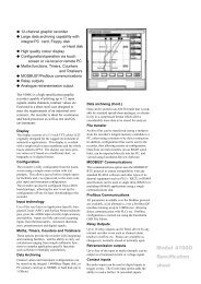
Figure 1-1 Overview <strong>of</strong> <strong>TC1028</strong> <strong>series</strong> thyrist<strong>or</strong> unit (500V version)<br />
<strong>TC1028</strong> User manual<br />
1-3
IDENTIFYING THE THYRISTOR UNITS<br />
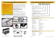
The standard (basic) version <strong>of</strong> the <strong>TC1028</strong> <strong>series</strong> <strong>of</strong> controllers is fitted with:<br />
• a thyrist<strong>or</strong> firing board (‘power board’) which generates thyrist<strong>or</strong> firing pulses and<br />
provides current and voltage measurement<br />
• a ‘driver board’ which produces signals to control thyrist<strong>or</strong> firing<br />
• a ‘potentiometer board’ to allow adjustment <strong>of</strong> delayed firing (inductive loads), and s<strong>of</strong>t<br />
start time<br />
• a ‘filter board’ to protect thyrist<strong>or</strong> unit operation from transient interference.<br />
As an option, the <strong>TC1028</strong> may be fitted with a board which plugs into the driver board and<br />
which converts the instantaneous current into an rms current measurement (‘RMS option<br />
board’). The RMS value <strong>of</strong> the load current is displayed on a bargraph and is retransmitted<br />
via a signal available on the user terminal block.<br />
The control system uses analogue feedback <strong>of</strong> load voltage squared (V2) <strong>or</strong> load current<br />
squared (I2), the highest value being automatically selected.<br />
<strong>TC1028</strong> <strong>units</strong> compensate f<strong>or</strong> supply variations in the range +10% to -15% <strong>of</strong> the<br />
nominal voltage.<br />
<strong>TC1028</strong> <strong>series</strong> thyrist<strong>or</strong> <strong>units</strong> are used f<strong>or</strong> control <strong>of</strong> electrical loads such as:<br />
• loads with large resistance variations as a function <strong>of</strong> temperature<br />
• transf<strong>or</strong>mer primaries<br />
• induct<strong>or</strong>s.<br />
The following features are found on the front panel:<br />
• potentiometer to adjust the initial firing delay on inductive loads, <strong>or</strong> s<strong>of</strong>t start duration<br />
• diagnostics connect<strong>or</strong><br />
• bargraph showing the mean <strong>or</strong> RMS current (optional)<br />
• potentiometer f<strong>or</strong> partial load failure detection adjustment<br />
• ‘Test’ pushbutton to test the PLF alarm adjustment<br />
• indicat<strong>or</strong> light to display PLF detection.<br />
1-4<br />
<strong>TC1028</strong> User manual
IDENTIFYING THE THYRISTOR UNITS<br />
Power supply<br />
connection screw<br />
Safety<br />
earth<br />
Filter<br />
LINE<br />
Internal thyrist<strong>or</strong><br />
protection fuse<br />
Power board<br />
Flat connection<br />
cable<br />
PLF contact<br />
terminal block<br />
LOAD<br />
Load<br />
connection<br />
Fan<br />
Filter board<br />
Ground<br />
bonding link<br />
Reference voltage<br />
<strong>Control</strong> terminal block<br />
Potentiometer<br />
board<br />
Driver board<br />
RMS option board<br />
Figure 1-2 Circuit boards f<strong>or</strong> the <strong>TC1028</strong> <strong>series</strong> thyrist<strong>or</strong> unit (500V version)<br />
<strong>TC1028</strong> User manual<br />
1-5
IDENTIFYING THE THYRISTOR UNITS<br />
<strong>TC1028</strong> thyrist<strong>or</strong>s have the following thyrist<strong>or</strong> firing modes:<br />
• ‘Phase angle’ - variation in the thyrist<strong>or</strong> firing angle<br />
• ‘Burst-firing’ - modulation <strong>of</strong> burst-firing duty cycle from 0 to 100%<br />
‘Burst mode’ firing is characterised by various modes:<br />
• ‘Single-cycle’ one cycle <strong>of</strong> firing <strong>or</strong> non-firing<br />
• ‘slow cycle’ burst-firing (modulation time 8s at 50% setpoint)<br />
• ‘fast cycle’ burst-firing (modulation time 0.8s at 50% setpoint)<br />
• burst-firing (fast <strong>or</strong> slow cycle) with <strong>phase</strong> angle s<strong>of</strong>t start<br />
• burst-firing (fast <strong>or</strong> slow cycle) with <strong>phase</strong> angle s<strong>of</strong>t start and end<br />
The s<strong>of</strong>t start f<strong>or</strong> large temperature coefficient <strong>resistive</strong> loads and the delayed firing angle in<br />
the first half-cycle when controlling inductive loads, minimise transient overcurrents. (Which<br />
otherwise can cause fuse blowing <strong>or</strong> trigger a protective circuit breaker.)<br />
The s<strong>of</strong>t start and end time can be adjusted between 0 and 0.25s via the potentiometer on the<br />
front panel.<br />
<strong>TC1028</strong> <strong>units</strong> have two types <strong>of</strong> current limit:<br />
• linear limit (adjusted by potentiometer on front panel)<br />
• threshold limit (adjusted by external potentiometer)<br />
The partial load failure detection circuit (PLF) detects 25% increases in load impedance<br />
(independent <strong>of</strong> supply voltage variations).<br />
PLF detection is adjusted by a potentiometer on the front panel, which is used to set the<br />
actual load current.<br />
PLF alarm signalling is provided by the alarm relay contacts and by the ‘Load Fail’ indicat<strong>or</strong><br />
light on the front panel.<br />
Thermal protection is provided by means <strong>of</strong> a thermal switch which senses fan failure <strong>or</strong><br />
heatsink over-temperature.<br />
<strong>TC1028</strong> <strong>units</strong> have active “enable”.<br />
An external 10V signal (32V max.) <strong>or</strong> a switch connected to the user terminal block are used<br />
to enable operation.<br />
Absence <strong>of</strong> the enable voltage <strong>or</strong> opening <strong>of</strong> the switch contacts causes inhibition <strong>of</strong> the<br />
controller.<br />
1-6<br />
<strong>TC1028</strong> User manual
TECHNICAL SPECIFICATION<br />
IDENTIFYING THE THYRISTOR UNITS<br />
(<strong>units</strong> rated between 300A and 500A)<br />
The <strong>TC1028</strong> is a power thyrist<strong>or</strong> unit designed to control an inductive industrial load <strong>or</strong> a load<br />
with a high current requirement at start-up.<br />
!<br />
Warning!<br />
It is the user’s responsibility to ensure, bef<strong>or</strong>e commissioning the controller, that<br />
all the nominal ratings <strong>of</strong> the controller are compatible with the conditions <strong>of</strong> use<br />
and the installation.<br />
Power<br />
Nominal current<br />
300A, 400A, 500A<br />
Nominal line-to-line voltage 100Vac to 690Vac (+10%, -15%)<br />
Inhibition below 80% <strong>of</strong> nominal voltage;<br />
response time
IDENTIFYING THE THYRISTOR UNITS<br />
<strong>Control</strong><br />
Power supply<br />
Self-supplied from power circuit (300A to 500A rated<br />
<strong>units</strong>) with reference <strong>phase</strong> (<strong>or</strong> neutral) connection<br />
Consumption: 20VA<br />
Analogue<br />
Input type<br />
Range Voltage : 0-5V; 1-5V; 0-10V <strong>or</strong> 2-10V<br />
Current : 0-20mA; 4-20mA<br />
Input impedance<br />
Voltage : ≥50kΩ<br />
Current : 250Ω<br />
Manual control<br />
5kΩ external potentiometer<br />
<strong>Thyrist<strong>or</strong></strong> firing modes<br />
The following may be reconfigured by the user:<br />
• Phase angle<br />
• Single-cycle (Burst-firing with one firing <strong>or</strong> non-firing<br />
cycle)<br />
• Fast cycle burst-firing<br />
(typical modulation time at 50% power : 0.8s)<br />
• Slow cycle burst-firing<br />
(typical modulation time at 50% power : 8s)<br />
• Fast cycle with adjustable s<strong>of</strong>t start between 0 and<br />
250ms (with <strong>or</strong> without s<strong>of</strong>t end)<br />
• Slow-cycle with adjustable s<strong>of</strong>t start between 0 and<br />
250ms (with <strong>or</strong> without s<strong>of</strong>t end)<br />
Delayed thyrist<strong>or</strong> firing<br />
overcurrents<br />
Enable / Inhibit<br />
Diagnostics<br />
<strong>Control</strong> type<br />
F<strong>or</strong> inductive loads, delayed firing in the first half-cycle <strong>of</strong><br />
burst-firing (without s<strong>of</strong>t start) eliminates transient<br />
Using external contacts <strong>or</strong> external voltage (10VDC) to<br />
enable<br />
Response time : enable, 2s; inhibit < 25ms<br />
Connect<strong>or</strong> f<strong>or</strong> diagnostic unit permits adjustment and<br />
test <strong>of</strong> thyrist<strong>or</strong> unit.<br />
<strong>Control</strong> <strong>of</strong> load voltage squared <strong>or</strong> load current squared<br />
Supply variation compensation<br />
Wiring<br />
Connections<br />
Shielded cable connected to ground at both ends<br />
0.5 2 mm to 1.0 2 mm conduct<strong>or</strong>s<br />
Tightening t<strong>or</strong>que 0.7Nm<br />
1-8<br />
<strong>TC1028</strong> User manual
IDENTIFYING THE THYRISTOR UNITS<br />
RMS option board<br />
Retransmissions<br />
Display<br />
RMS load current<br />
DC signal (0-10V) prop<strong>or</strong>tional to the actual load current.<br />
Retransmission output on the user terminal block<br />
Display <strong>of</strong> RMS current using 10-segment bargraph<br />
Current limit<br />
Linear limit<br />
Threshold limit<br />
Prop<strong>or</strong>tional load current limit<br />
(from 20 to 100% <strong>of</strong> the nominal current) Adjustment<br />
using potentiometer on front panel<br />
Maximum load current limit<br />
Adjustment using external potentiometer<br />
Partial load failure detection<br />
Alarm<br />
Detection <strong>of</strong> 20% decrease in current<br />
Adjustment by potentiometer marked ‘Adjust’ on front<br />
panel<br />
Test<br />
Using ‘Test’ push button on front panel<br />
Signalling<br />
‘Load fail’ indicat<strong>or</strong> light on front panel<br />
Alarm relay contacts open in alarm state (in standard<br />
version)<br />
Alarm relay contacts closed in alarm state (IPF option)<br />
Bargraph<br />
Display<br />
• Instantaneous current (filtered mean value) f<strong>or</strong> the<br />
adjustment <strong>of</strong> initial firing <strong>of</strong> thyrist<strong>or</strong>s in the case <strong>of</strong><br />
inductive loads (basic version)<br />
• RMS value <strong>of</strong> load current in ‘Phase angle’ and ‘Fast<br />
cycle’ firing modes with <strong>or</strong> without s<strong>of</strong>t start <strong>or</strong> end<br />
(with RMS option board)<br />
!<br />
Warning!<br />
In <strong>or</strong>der to maintain its 'leading edge', Eurotherm may have to make changes to its<br />
specifications without advance notice.F<strong>or</strong> any further inf<strong>or</strong>mation, <strong>or</strong> if in doubt,<br />
please contact Eurotherm <strong>Control</strong>s.<br />
<strong>TC1028</strong> User manual<br />
1-9
IDENTIFYING THE THYRISTOR UNITS<br />
PRODUCT CODE FOR <strong>TC1028</strong> SERIES<br />
<strong>TC1028</strong> Nominal Nominal Fan Input Firing Manual Options 96 00<br />
current voltage supply signal mode<br />
Nominal current Code<br />
300 amps 300A<br />
400 amps 400A<br />
500 amps 500A<br />
750 amps * 750A<br />
900 amps * 900A<br />
1200 amps * 1200A<br />
1650 amps * 1650A<br />
Nominal voltage Code<br />
100 volts 100V<br />
110 volts 110V<br />
115 volts 115V<br />
120 volts 120V<br />
200 volts 200V<br />
220 volts 220V<br />
230 volts 230V<br />
240 volts 240V<br />
277 volts 277V<br />
380 volts 380V<br />
400 volts 400V<br />
415 volts 415V<br />
440 volts 440V<br />
480 volts 480V<br />
500 volts 500V<br />
690 volts 690V<br />
Fan supply<br />
Code<br />
Self-supplied<br />
(300A to 500A rated <strong>units</strong>) 000<br />
External voltage *<br />
(ratings ≥ 750A) :<br />
115 volts 115V<br />
230 volts 230V<br />
Input signal<br />
Code<br />
0-5 V 0V5<br />
1-5 V 1V5<br />
0-10 V 0V10<br />
2-10 V 2V10<br />
0-20 mA 0mA20<br />
4-20 mA 4mA20<br />
Input signal<br />
Code<br />
0-5 V 0V5<br />
1-5 V 1V5<br />
0-10 V 0V10<br />
2-10 V 2V10<br />
0-20 mA 0mA20<br />
4-20 mA 4mA20<br />
<strong>Thyrist<strong>or</strong></strong> firing mode<br />
Phase angle<br />
Single-cycle<br />
‘Fast cycle’ burst-firing (0.8s)<br />
‘Fast cycle’ burst-firing with<br />
s<strong>of</strong>t start<br />
‘Fast cycle’ burst-firing with<br />
s<strong>of</strong>t start & end<br />
‘Slow cycle’ burst-firing (8s)<br />
‘Slow cycle’ burst-firing with<br />
s<strong>of</strong>t start<br />
‘Slow cycle’ burst-firing with<br />
s<strong>of</strong>t start & end<br />
Manual language<br />
English<br />
French<br />
German<br />
Italian<br />
Dutch<br />
Swedish<br />
Code<br />
PA<br />
SGL<br />
FC<br />
SFC<br />
SDF<br />
SC<br />
SSC<br />
SDS<br />
Code<br />
ENG<br />
FRA<br />
GER<br />
ITA<br />
NED<br />
SWE<br />
Options<br />
Code<br />
RMS current<br />
retransmission and display RMS<br />
60Hz frequency<br />
60H<br />
PLF alarm contacts closed<br />
in alarm state<br />
IPF<br />
Fuse-blown indicat<strong>or</strong><br />
microswitch<br />
FUMS<br />
No internal fuse NOFUSE<br />
Separate MC control unit *<br />
f<strong>or</strong> ≥ 750A rated <strong>units</strong>;<br />
not available f<strong>or</strong> 690V MC<br />
* See addendum HA174804ENG001<br />
1-10<br />
<strong>TC1028</strong> User manual
IDENTIFYING THE THYRISTOR UNITS<br />
Example <strong>of</strong> product code<br />
<strong>TC1028</strong> controller and installation parameters<br />
Nominal load current<br />
Nominal supply voltage<br />
Analogue input signal<br />
Firing mode<br />
Options<br />
250 amps<br />
440 volts line-to-line<br />
0 to 10 volts<br />
‘Fast cycle’ burst-firing with s<strong>of</strong>t start<br />
RMS current display and retransmission<br />
‘Partial load failure’ detection alarm relay contacts closed in<br />
alarm state<br />
Fuse-blown indication microswitch<br />
<strong>Control</strong>ler code:<br />
<strong>TC1028</strong> / 300A / 440V / 000 / 0V10 / SFC / ENG / RMS / IPF / FUMS / 96 / 00<br />
!<br />
Warning!<br />
The nominal voltage <strong>of</strong> the <strong>TC1028</strong> controller must c<strong>or</strong>respond to the supply<br />
voltage used in <strong>or</strong>der to eliminate problems <strong>of</strong> the controller not operating below<br />
80% <strong>of</strong> the nominal voltage<br />
<strong>TC1028</strong> User manual<br />
1-11
IDENTIFYING THE THYRISTOR UNITS<br />
SERIAL NUMBER LABELS<br />
Two identification labels (which include the controller product code) and one configuration<br />
label provide all the inf<strong>or</strong>mation relating to the fact<strong>or</strong>y settings <strong>of</strong> the controller.<br />
One identification label is located externally on the right hand side <strong>of</strong> the unit.<br />
EUROTHERM 2.20<br />
WORTHING, ENGLAND : 1903 268500<br />
MODEL : <strong>TC1028</strong>/300A/440V/000/0V10/SFC/RMS/ENG/IPF/FUMS/96/00<br />
SERIAL No. : LC1111/001/001/11/97<br />
RATING : 1 PHASE 300A 440V 50Hz<br />
AUXILIARY POWER SUPPLY : SELF-SUPPLIED<br />
MADE IN FRANCE<br />
Figure 1-3 Example <strong>of</strong> identification label f<strong>or</strong> a <strong>TC1028</strong> controller<br />
The inf<strong>or</strong>mation c<strong>or</strong>responds to the product code example<br />
The second identification label and the configuration label are located inside the controller.<br />
SERIAL No : LC1111/001/001/11/97<br />
<strong>TC1028</strong><br />
FACTORY SETTINGS :<br />
INPUT : 0-10V DC<br />
FIRING : FAST CYCLE BURST MODE<br />
OPTION(S) : FUSE-BLOWN INDICATION SWITCH<br />
CONTACTS CLOSED IN ALARM STATE<br />
RMS BOARD<br />
ANY NON-SPECIFIED FUSE INVALIDATES GUARANTEE (SEE USER MANUAL<br />
HA174804ENG)<br />
Figure 1-4 Example <strong>of</strong> configuration label f<strong>or</strong> a <strong>TC1028</strong> controller<br />
!<br />
Warning!<br />
Following any re-configuration on the part <strong>of</strong> the user, there is no guarantee that<br />
the controller will c<strong>or</strong>respond to the label inf<strong>or</strong>mation.<br />
1-12<br />
<strong>TC1028</strong> User manual
INSTALLATION<br />
Chapter 2<br />
INSTALLATION<br />
Contents<br />
Page<br />
INSTALLATION - SAFETY . . . . . . . . . . . . . . . . . . . . . . . . . .2-2<br />
DIMENSIONAL DETAILS . . . . . . . . . . . . . . . . . . . . . . . . . . .2-3<br />
MECHANICAL MOUNTING . . . . . . . . . . . . . . . . . . . . . . . . .2-5<br />
INSTALLATION DETAILS . . . . . . . . . . . . . . . . . . . . . . . . . . .2-6<br />
<strong>TC1028</strong> User manual<br />
2-1
INSTALLATION<br />
Chapter 2 INSTALLATION<br />
INSTALLATION - SAFETY<br />
Danger!<br />
<strong>TC1028</strong> <strong>units</strong> must be installed by personnel trained to w<strong>or</strong>k with low voltage<br />
electrical equipment in an industrial environment.<br />
Units must be installed in fan-cooled electrical cabinets, to ensure that<br />
condensation and pollution are excluded.<br />
The cabinet must be closed and bonded to the safety earth in acc<strong>or</strong>dance with<br />
IEC 364 <strong>or</strong> current national Standards.<br />
F<strong>or</strong> installations which are fan-cooled, it is recommended that a fan-failure detection device<br />
<strong>or</strong> a thermal safety cut-out should be fitted in the cabinet.<br />
The <strong>TC1028</strong> <strong>series</strong> <strong>of</strong> <strong>units</strong> may be bulkhead mounted.<br />
The <strong>units</strong> must be mounted with the heatsink positioned vertically, with no obstructions above<br />
<strong>or</strong> below which could inhibit <strong>or</strong> impede airflow.<br />
If several <strong>units</strong> are mounted in the same cabinet, they must be arranged in such a way that air<br />
expelled from one cannot be drawn into the unit located above it.<br />
!<br />
Warning!<br />
The <strong>units</strong> are designed to be used at an ambient temperature less than <strong>or</strong> equal to<br />
50°C (40°C f<strong>or</strong> 500A nominal <strong>units</strong>).<br />
Leave a minimum gap <strong>of</strong> 5cm between two <strong>units</strong> placed side by side.<br />
Excessive overheating may lead to inc<strong>or</strong>rect operation <strong>of</strong> the unit. This may in<br />
turn cause damage to the components.<br />
<strong>TC1028</strong> <strong>series</strong> power <strong>units</strong> have permanent fan cooling.<br />
2-2<br />
<strong>TC1028</strong> User manual
INSTALLATION<br />
DIMENSIONAL DETAILS<br />
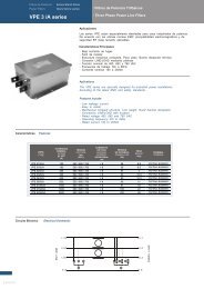
Dimensions and weights <strong>of</strong> <strong>TC1028</strong> controllers (<strong>units</strong> rated between 300A and 500A)<br />
are given<br />
• in Figure 2-1<br />
• and in Table 2-1<br />
Do<strong>or</strong> fixing<br />
Upper protection cover<br />
V<br />
R<br />
100<br />
50<br />
0<br />
Load Fail<br />
Déf. Charge<br />
Adjust<br />
Seuil<br />
Test<br />
I limit<br />
Limit. I<br />
B<br />
Delay<br />
Retard<br />
A<br />
ε<br />
EUROTHERM<br />
110°<br />
Lower protection cover<br />
U<br />
C<br />
D<br />
G<br />
Do<strong>or</strong> open<br />
Figure 2-1 Overall dimensions with upper protective cover<br />
<strong>TC1028</strong> User manual<br />
2-3
INSTALLATION<br />
Dimensions Values Description<br />
A 425mm Height without protective cover<br />
B 570mm Height with cover<br />
C 133mm Width (up to 500V)<br />
248mm<br />
Width (690V)<br />
D 268mm Depth<br />
E 88mm Width between fixing holes (up to 500V)<br />
203mm<br />
Width between fixing holes (690V)<br />
F 328mm Height between fixing holes<br />
G 557mm Depth with do<strong>or</strong> open<br />
K 350mm Height <strong>of</strong> side faces<br />
R 20mm Distance between ‘Earth’ busbar and panel<br />
U 150mm Depth between ‘LOAD’ terminal and panel<br />
V 170mm Depth between ‘LINE’ terminal and panel<br />
Weight 10kg Up to 500V<br />
19kg<br />
690V<br />
Table 2-1 Dimensions and weights <strong>of</strong> <strong>TC1028</strong> <strong>units</strong> (300A to 500A)<br />
2-4<br />
<strong>TC1028</strong> User manual
MECHANICAL MOUNTING<br />
INSTALLATION<br />
<strong>TC1028</strong> controllers have two protective covers (upper and lower).<br />
The controllers may be mounted with their protective covers in position. However, the upper<br />
protective cover must be removed to make electrical connections.<br />
Having drilled the supp<strong>or</strong>t panel to the dimensional values given above, insert the fixing<br />
screws halfway into the bulkhead / mounting plate holes.<br />
Offer up the controller by first engaging the heads <strong>of</strong> the upper screws in the respective holes<br />
on the upper section.<br />
Lower the unit making sure that it engages properly on the lower screws.<br />
Then slide the unit down completely until it is in position.<br />
Tighten the four screws c<strong>or</strong>rectly.<br />
<strong>TC1028</strong> User manual<br />
2-5
INSTALLATION<br />
INSTALLATION DETAILS<br />
<strong>TC1028</strong> <strong>series</strong> <strong>units</strong> are designed to be mounted directly on to a panel using the fixing points<br />
located on the rear <strong>of</strong> the <strong>units</strong>.<br />
Protection<br />
cover<br />
Ø 9<br />
13<br />
4 drilling holes<br />
f<strong>or</strong> M8 screws<br />
Ø18<br />
K<br />
F<br />
Ø 9<br />
10<br />
E<br />
C<br />
Figure 2-2 Mounting details (300A to 500A rated <strong>units</strong>)<br />
2-6<br />
<strong>TC1028</strong> User manual
WIRING<br />
Chapter 3<br />
WIRING<br />
Contents<br />
Page<br />
WIRING - SAFETY . . . . . . . . . . . . . . . . . . . . . . . . . . . . . . . . .3-2<br />
CONNECTING THE POWER CABLES . . . . . . . . . . . . . . . .3-3<br />
REFERENCE VOLTAGE CONNECTION . . . . . . . . . . . . . . .3-6<br />
CONTROL CABLES . . . . . . . . . . . . . . . . . . . . . . . . . . . . . . . .3-7<br />
MOUNTING . . . . . . . . . . . . . . . . . . . . . . . . . . . . . . . . . . .3-7<br />
CONNECTION OF THE SHIELD TO THE GROUND .3-8<br />
CONTROL TERMINAL BLOCK . . . . . . . . . . . . . . . . . . . . . .3-9<br />
INPUT SIGNALS . . . . . . . . . . . . . . . . . . . . . . . . . . . . . . . . . .3-11<br />
EXTERNAL ANALOGUE INPUT . . . . . . . . . . . . . . . .3-12<br />
CONTROL OF MULTIPLE UNITS . . . . . . . . . . . . . . . .3-13<br />
Wiring in parallel . . . . . . . . . . . . . . . . . . . . . . . . . . . . . . .3-13<br />
Wiring in <strong>series</strong> . . . . . . . . . . . . . . . . . . . . . . . . . . . . . . . .3-14<br />
MANUAL CONTROL WIRING . . . . . . . . . . . . . . . . . .3-15<br />
EXTERNAL CURRENT LIMIT WIRING . . . . . . . . . . .3-16<br />
RETRANSMISSION SIGNAL WIRING . . . . . . . . . . . . . . .3-18<br />
SINGLE-PHASE LOAD WIRING DIAGRAM . . . . . . . . . .3-19<br />
THREE-PHASE LOAD WIRING DIAGRAMS . . . . . . . . . .3-20<br />
LOAD IN STAR WITH NEUTRAL . . . . . . . . . . . . . . . .3-21<br />
LOAD IN OPEN DELTA . . . . . . . . . . . . . . . . . . . . . . . .3-22<br />
LOAD IN STAR WITHOUT NEUTRAL OR IN<br />
CLOSED DELTA (TWO PHASE CONTROL) . . . . . . .3-23<br />
PLF ALARM . . . . . . . . . . . . . . . . . . . . . . . . . . . . . . . . . . . . .3-24<br />
<strong>TC1028</strong> User manual<br />
3-1
WIRING<br />
Chapter 3 WIRING<br />
WIRING- SAFETY<br />
Danger!<br />
Wiring must only be carried out by personnel who are qualified to w<strong>or</strong>k in a low<br />
voltage industrial environment.<br />
It is the user’s responsibility to wire and protect the installation in acc<strong>or</strong>dance with<br />
current pr<strong>of</strong>essional Standards.<br />
A suitable device ensuring electrical isolation between the equipment and the<br />
supply must be installed upstream <strong>of</strong> the unit in <strong>or</strong>der to permit safe maintenance.<br />
<strong>TC1028</strong> <strong>series</strong> <strong>units</strong> have two protective covers : upper and lower.<br />
In <strong>or</strong>der to make wiring easier, the upper cover should be removed.<br />
After connection and bef<strong>or</strong>e powering up, replace the upper protective cover to ensure the<br />
specified degree <strong>of</strong> protection.<br />
Danger!<br />
• Bef<strong>or</strong>e any connection <strong>or</strong> disconnection, ensure that power and control<br />
cables <strong>or</strong> leads are isolated from voltage sources.<br />
• F<strong>or</strong> safety reasons, the safety earth cable must be connected bef<strong>or</strong>e any<br />
other connection is made during wiring and it must be the last cable to be<br />
disconnected.<br />
The safety earth is connected to the screw located on the strip provided f<strong>or</strong> this purpose in the<br />
upper part <strong>of</strong> the unit, behind the <strong>phase</strong> terminal and labelled:<br />
Danger!<br />
• To ensure c<strong>or</strong>rect grounding <strong>of</strong> the <strong>TC1028</strong> unit, make sure that it is<br />
properly mounted on the reference ground surface (panel <strong>or</strong> bulkhead).<br />
Failing this, it is necessary to add a ground connection at most 10cms long<br />
between the earth connection and the reference ground surface.<br />
• This connection, which is intended to ensure good ground continuity, can<br />
never be used to replace the safety earth connection.<br />
3-2<br />
<strong>TC1028</strong> User manual
CONNECTING THE POWER CABLES<br />
WIRING<br />
The supply power cable passes through an opening in the upper protective cover <strong>of</strong> the<br />
<strong>TC1028</strong> unit.<br />
In <strong>or</strong>der to make connection <strong>of</strong> this cable easier, the upper cover <strong>of</strong> the unit is removed.<br />
To remove the cover:<br />
• open the access do<strong>or</strong> by undoing the front screw located on the top left hand<br />
side <strong>of</strong> the do<strong>or</strong><br />
• lift the do<strong>or</strong> in <strong>or</strong>der to release it from its slots<br />
• open the do<strong>or</strong> completely by pulling it towards you<br />
• remove the upper cover by unscrewing the two fixing nuts (by sliding it 1cm<br />
f<strong>or</strong>wards to release the two catches located at the rear), and then raising it.<br />
The supply connection is made on the fuse stud on the upper part <strong>of</strong> the unit labelled LINE<br />
(see Figure 3-1).<br />
The load power cable passes inside the unit through a cable gland located below the unit.<br />
The aperture <strong>of</strong> this cable gland is up to 38mm.<br />
The load connection is made on the screw located on the lower part <strong>of</strong> the unit, labelled<br />
LOAD (see Figure 3-1).<br />
The power terminal capacities are given in Table 3-1.<br />
Tightening t<strong>or</strong>ques should not exceed the limits given in this table.<br />
Terminal<br />
Wiring details<br />
Supply and load 185 to 2 x 150mm 2<br />
Earth cable 95 to 185mm 2<br />
Fuse stud<br />
M10<br />
Tightening t<strong>or</strong>que<br />
25Nm<br />
Load screw<br />
M12<br />
Tightening t<strong>or</strong>que<br />
43.5Nm<br />
Earth screw<br />
M12<br />
Tightening t<strong>or</strong>que<br />
43.5Nm<br />
Table 3-1 Power connection details (300A to 500A)<br />
The cross-section <strong>of</strong> the conduct<strong>or</strong>s to be used must comply with Standard IEC943.<br />
<strong>TC1028</strong> User manual<br />
3-3
WIRING<br />
Safety earth connection<br />
<strong>Thyrist<strong>or</strong></strong><br />
protection fuse<br />
LINE<br />
Supply <strong>phase</strong><br />
connection<br />
Load<br />
connection<br />
LOAD<br />
Figure 3-1 Fixing points f<strong>or</strong> power cables (300A to 500A unit)<br />
3-4<br />
<strong>TC1028</strong> User manual
WIRING<br />
Distance between:<br />
‘Earth’ busbar and upper fixing hole<br />
‘Earth’ busbar and left fixing hole<br />
‘LOAD’ terminal and lower fixing hole<br />
‘LOAD’ terminal and left fixing hole<br />
‘LINE’ terminal and upper fixing hole<br />
Dimensions<br />
30mm<br />
96mm<br />
70mm<br />
20mm<br />
20mm<br />
Table 3-2 Details <strong>of</strong> power cabling<br />
!<br />
Warning!<br />
The power cables leading to a load pass through a cable gland<br />
(aperture to 38mm), which must be tightened carefully after wiring.<br />
<strong>TC1028</strong> User manual<br />
3-5
WIRING<br />
REFERENCE VOLTAGE CONNECTION<br />
The reference voltage (second <strong>phase</strong> <strong>or</strong> neutral) used by the electronics is connected to a<br />
plug-in user terminal block, located on the right hand side below the unit.<br />
The maximum cross-section <strong>of</strong> the conduct<strong>or</strong>s is 1.5 mm 2 ; tightening t<strong>or</strong>que <strong>of</strong> control<br />
terminals : 0.7Nm.<br />
To second <strong>phase</strong> <strong>or</strong> neutral<br />
depending on wiring <strong>of</strong> load<br />
PLF<br />
<strong>Control</strong> cable<br />
clamp N/L2 71<br />
<br />
<br />
Fusible<br />
1 A<br />
Not used<br />
View <strong>of</strong> unit<br />
from below<br />
Reference voltage<br />
connection ternminal block<br />
Figure 3-2 Reference voltage connection terminal block<br />
The reference voltage (second <strong>phase</strong> <strong>or</strong> neutral) must c<strong>or</strong>respond to the load configuration<br />
voltage.<br />
A 1A external fuse must be fitted to protect the reference voltage wiring.<br />
3-6<br />
<strong>TC1028</strong> User manual
WIRING<br />
CONTROL CABLES<br />
!<br />
Warning!<br />
<strong>Control</strong> connections should be made using shielded cables grounded at both<br />
ends in <strong>or</strong>der to ensure satisfact<strong>or</strong>y immunity against interference.<br />
Separate the control cables from the power cables in the cable trays.<br />
Mounting<br />
The control wires must be grouped together in a shielded cable passing through the cable<br />
clamp located below the unit.<br />
<strong>Control</strong> cable clamp<br />
Tightening screw<br />
Lower cover<br />
Stirrup<br />
View <strong>of</strong> unit<br />
from below<br />
Figure 3-3 Location <strong>of</strong> control cable clamp<br />
!<br />
Imp<strong>or</strong>tant!<br />
To facilitate earthing <strong>of</strong> the cable shield and to ensure maximum immunity<br />
from electromagnetic interference, the metal cable clamp is bonded directly to<br />
the ground <strong>of</strong> the unit.<br />
<strong>TC1028</strong> User manual<br />
3-7
WIRING<br />
Connection <strong>of</strong> the shield to the ground<br />
To insert the control cable and earth its shield:<br />
• Strip the shielded cable as shown in Figure 3-4a<br />
The control wires must be long enough f<strong>or</strong> connection to be made to the user terminal blocks<br />
on the boards, whilst the bare screen is grounded at the metal cable clamp, when the do<strong>or</strong> is<br />
open.<br />
Wiring inside the unit should be as sh<strong>or</strong>t as possible.<br />
<strong>Control</strong> wires<br />
20 to 40 cm<br />
<strong>Control</strong> wires<br />
Shield<br />
<br />
<br />
1·5 to 2 cm<br />
<br />
<br />
<br />
Shield folded back<br />
Insulating sheath<br />
a)<br />
Insulating sheath<br />
b)<br />
Figure 3-4 <strong>Control</strong> cable stripping<br />
• Fold back the shield on to the insulating sheath (Figure 3-4b)<br />
• Insert the cable into the metal cable clamp so that the shield is located in the stirrup and<br />
not inside the unit (at least, not beyond the lower cover).<br />
• Tighten the stirrup (4x1 flat-bladed screwdriver; tightening t<strong>or</strong>que 0.7Nm)<br />
Cable<br />
<br />
<br />
<br />
<br />
<br />
<br />
<br />
Cable clamp<br />
Wires<br />
Lower cover<br />
Tighening screw<br />
Shield folded back<br />
View from left side<br />
Figure 3-5 Cable tightening and shield grounding<br />
The possible diameter <strong>of</strong> the cables with the shield folded back is from 5mm to 10mm per<br />
cable clamp.<br />
3-8<br />
<strong>TC1028</strong> User manual
WIRING<br />
CONTROL TERMINAL BLOCK<br />
The following connections are made on the driver board user terminal block:<br />
• input signal (external <strong>or</strong> manual)<br />
• “enable” f<strong>or</strong> controller operation<br />
• threshold current limit<br />
• load current and voltage retransmission<br />
• logic signal output to drive a solid state relay in ‘Master-Slave’ operation<br />
Access to the user terminal block is by opening the front do<strong>or</strong>.<br />
Danger!<br />
Live parts may be exposed when the do<strong>or</strong> is open if the <strong>TC1028</strong> controller is<br />
powered up.<br />
9<br />
8<br />
7<br />
6<br />
5<br />
4<br />
3<br />
Driver board<br />
ENABLE<br />
SLAVE OUTPUT<br />
AUTO INPUT<br />
MANUAL INPUT<br />
I LIMIT INPUT<br />
LOAD I OUTPUT<br />
LOAD V OUTPUT<br />
+10V<br />
0V<br />
2<br />
1<br />
Figure 3-6 Labelling <strong>of</strong> <strong>TC1028</strong> control terminals<br />
<strong>Control</strong> terminal block terminal capacity 0.22mm 2 to 1.5mm 2 .<br />
<strong>Control</strong> terminal tightening t<strong>or</strong>que : 0.7Nm<br />
The input is isolated from the power supply and from the load circuit.<br />
<strong>TC1028</strong> User manual<br />
3-9
WIRING<br />
Terminal Labelling Function<br />
1 0V Common 0V<br />
2 +10V +10V user voltage<br />
3 LOAD V OUTPUT Output f<strong>or</strong> load voltage measurement retransmission<br />
4 LOAD I OUTPUT Output f<strong>or</strong> load current measurement retransmission<br />
5 I LIMIT INPUT Input f<strong>or</strong> threshold current limit<br />
6 MANUAL INPUT Input f<strong>or</strong> manual control signal<br />
7 AUTO INPUT Input f<strong>or</strong> automatic control signal<br />
8 SLAVE FIRING OUTPUT Logic output to drive other <strong>units</strong> in ‘Master-Slave’<br />
operation<br />
9 ENABLE INPUT Enables thyrist<strong>or</strong> operation<br />
Table 3-3 Terminal designation <strong>of</strong> <strong>TC1028</strong> thyrist<strong>or</strong> unit control terminal block<br />
3-10<br />
<strong>TC1028</strong> User manual
INPUT SIGNALS<br />
WIRING<br />
The control wires are connected on the plug-in user terminal block located on the driver<br />
board.<br />
The user terminal block can be accessed with the front do<strong>or</strong> open.<br />
To open the do<strong>or</strong> undo the front screw, release the do<strong>or</strong> from its notches by lifting it up, then<br />
pull it towards you.<br />
Danger!<br />
Live parts may be exposed when the do<strong>or</strong> is open if the controller is powered<br />
up.<br />
The <strong>units</strong> may be controlled by an external analogue signal (from a temperature controller <strong>or</strong><br />
another signal source) <strong>or</strong> manually by an external potentiometer.<br />
<strong>TC1028</strong> User manual<br />
3-11
WIRING<br />
External analogue input<br />
The <strong>TC1028</strong> may be configured f<strong>or</strong> voltage input <strong>or</strong> current input signals.<br />
Signal type Signal level Input impedance<br />
Voltage 0 - 5V 50kΩ<br />
1 - 5V<br />
0 - 10V<br />
2 - 10V<br />
Current 0 - 20mA<br />
4 - 20mA 250Ω<br />
Table 3-4 <strong>TC1028</strong> Input signals<br />
The external signal is applied to terminals 1 & 7 <strong>of</strong> the control terminal block<br />
(‘+’ on terminal 7).<br />
Contacts N/C:<br />
<strong>Control</strong>ler enable<br />
+<br />
<strong>Control</strong><br />
signal<br />
(Contacts open:<br />
inhibited)<br />
9<br />
8<br />
7<br />
6<br />
5<br />
Driver board<br />
ENABLE<br />
SLAVE OUTPUT<br />
AUTO INPUT<br />
MANUAL INPUT<br />
I LIMIT INPUT<br />
LOAD I OUTPUT<br />
LOAD V OUTPUT<br />
+10V<br />
0V<br />
4<br />
3<br />
2<br />
1<br />
Figure 3-7 Wiring <strong>of</strong> external control signal<br />
F<strong>or</strong> n<strong>or</strong>mal operation <strong>of</strong> the <strong>TC1028</strong> <strong>series</strong> controller, also connect:<br />
• ‘Enable’ input (terminal 9) to the ‘+10V user’ voltage (terminal 2)<br />
• ‘Current limit’ input (terminal 5) to the ‘+10V user’ voltage<br />
• ‘Manual control’ input (terminal 6) to terminal 1 ‘0V’.<br />
3-12<br />
<strong>TC1028</strong> User manual
<strong>Control</strong> <strong>of</strong> multiple <strong>units</strong><br />
WIRING<br />
The inputs <strong>of</strong> several controllers may be wired in parallel <strong>or</strong> in <strong>series</strong>.<br />
F<strong>or</strong> this type <strong>of</strong> wiring all the thyrist<strong>or</strong> <strong>units</strong> must have the same mode <strong>of</strong> firing and the inputs<br />
must be configured f<strong>or</strong> the same signal type.<br />
Wiring in parallel<br />
The inputs must be configured as voltage inputs<br />
The input impedance per controller is 50kΩ<br />
The current required f<strong>or</strong> each controller is 0.2mA at full scale.<br />
<strong>Control</strong> signal<br />
+<br />
0-5 V, 1-5 V, 0-10 V, 2-10 V<br />
Contacts N/C:<br />
<strong>Control</strong>ler enable<br />
(Contacts open: inhibited)<br />
ENABLE<br />
SLAVE CONTROL<br />
AUTO INPUT<br />
MANUAL INPUT<br />
I LIMIT INPUT<br />
LOAD I OUTPUT<br />
LOAD V OUTPUT<br />
+10V<br />
0V<br />
ENABLE<br />
SLAVE CONTROL<br />
AUTO INPUT<br />
MANUAL INPUT<br />
I LIMIT INPUT<br />
LOAD I OUTPUT<br />
LOAD V OUTPUT<br />
+10V<br />
0V<br />
ENABLE<br />
SLAVE CONTROL<br />
AUTO INPUT<br />
MANUAL INPUT<br />
I LIMIT INPUT<br />
LOAD I OUTPUT<br />
LOAD V OUTPUT<br />
+10V<br />
0V<br />
9<br />
8<br />
7<br />
6<br />
5<br />
4<br />
3<br />
2<br />
1<br />
9<br />
8<br />
7<br />
6<br />
5<br />
4<br />
3<br />
2<br />
1<br />
9<br />
8<br />
7<br />
6<br />
5<br />
4<br />
3<br />
2<br />
1<br />
Driver board 1 Driver board 2 Driver board 3<br />
Figure 3-8 Parallel input wiring<br />
<strong>TC1028</strong> User manual<br />
3-13
WIRING<br />
Wiring in <strong>series</strong><br />
The inputs must be configured as current inputs.<br />
Wiring in <strong>series</strong> is possible if all the controllers are configured f<strong>or</strong> the same current signal<br />
(0 to 20mA, f<strong>or</strong> example).<br />
F<strong>or</strong> 0 to 20mA and 4 to 20mA inputs, the impedance <strong>of</strong> an input is 250Ω.<br />
F<strong>or</strong> each input, 5 volts are required (f<strong>or</strong> a current <strong>of</strong> 20mA).<br />
+<br />
<strong>Control</strong> signal 0 - 20 mA, 4 - 20 mA<br />
Contacts N/C:<br />
<strong>Control</strong>ler enable<br />
(Contacts open : inhibited)<br />
ENABLE<br />
SLAVE CONTROL<br />
AUTO INPUT<br />
MANUAL INPUT<br />
I LIMIT INPUT<br />
LOAD I OUTPUT<br />
LOAD V OUTPUT<br />
+10V<br />
0V<br />
ENABLE<br />
SLAVE CONTROL<br />
AUTO INPUT<br />
MANUAL INPUT<br />
I LIMIT INPUT<br />
LOAD I OUTPUT<br />
LOAD V OUTPUT<br />
+10V<br />
0V<br />
ENABLE<br />
SLAVE CONTROL<br />
AUTO INPUT<br />
MANUAL INPUT<br />
I LIMIT INPUT<br />
LOAD I OUTPUT<br />
LOAD V OUTPUT<br />
+10V<br />
0V<br />
9<br />
8<br />
7<br />
6<br />
5<br />
4<br />
3<br />
2<br />
1<br />
9<br />
8<br />
7<br />
6<br />
5<br />
4<br />
3<br />
2<br />
1<br />
9<br />
8<br />
7<br />
6<br />
5<br />
4<br />
3<br />
2<br />
1<br />
Driver board 1 Driver board 2 Driver board 3<br />
Figure 3-9 Series input wiring<br />
3-14<br />
<strong>TC1028</strong> User manual
Manual control wiring<br />
The <strong>TC1028</strong> can be controlled by an external potentiometer (manual control).<br />
A 4.7kΩ to 10kΩ potentiometer should be connected between terminals 1 (‘0V’)<br />
and 2 (‘+10V’). The wiper is connected to terminal 6 (‘Manual input’).<br />
To use manual control, the controller input should be configured to 0 - 10V (see Product<br />
code).<br />
WIRING<br />
4·7 to 10kΩ potentiometer<br />
100% 0%<br />
Contacts N/C:<br />
<strong>Control</strong>ler enable<br />
(Contacts open : inhibited)<br />
9<br />
8<br />
7<br />
6<br />
5<br />
Driver board<br />
ENABLE<br />
SLAVE CONTROL<br />
AUTO INPUT<br />
MANUAL INPUT<br />
I LIMIT INPUT<br />
LOAD I OUTPUT<br />
LOAD V OUTPUT<br />
+10V<br />
0V<br />
4<br />
3<br />
2<br />
1<br />
Figure 3-10 Wiring <strong>of</strong> manual input f<strong>or</strong> <strong>TC1028</strong><br />
When manual control is used, terminal 7 <strong>of</strong> the external input labelled ‘Automatic<br />
input’ must be connected to ‘0V’ (terminal 1).<br />
!<br />
Warning!<br />
If the input signal is not disconnected from terminal 7, the two signals<br />
(external and manual) are added together.<br />
<strong>TC1028</strong> User manual<br />
3-15
WIRING<br />
External current limit wiring<br />
<strong>TC1028</strong> <strong>series</strong> thyrist<strong>or</strong> <strong>units</strong> have two types <strong>of</strong> current limit (see Chapter 5 ‘Operation’):<br />
• linear limit (internal limit) and<br />
• threshold limit (external limit).<br />
External current limit is controlled by a voltage level <strong>or</strong> by an external potentiometer, and<br />
may be used with automatic external control as well as with manual control.<br />
External current limit may be adjusted in three different ways.<br />
1. Adjustment by external voltage<br />
To implement threshold limit, a 0 - 10V external voltage should be connected between<br />
terminals 5 (‘I Limit’) and 1 (‘0V’), terminal 5 is positive.<br />
+<br />
External current<br />
limit voltage<br />
(0 to 10V)<br />
Contacts N/C:<br />
<strong>Control</strong>ler enable<br />
(Contacts open : inhibited)<br />
9<br />
8<br />
7<br />
6<br />
Driver board<br />
ENABLE<br />
SLAVE CONTROL<br />
AUTO INPUT<br />
MANUAL INPUT<br />
I LIMIT INPUT<br />
LOAD I OUTPUT<br />
LOAD V OUTPUT<br />
+10V<br />
0V<br />
5<br />
4<br />
3<br />
2<br />
1<br />
Figure 3-11 Wiring <strong>of</strong> external voltage f<strong>or</strong> threshold current limit<br />
3-16<br />
<strong>TC1028</strong> User manual
WIRING<br />
2. Adjustment by potentiometer<br />
F<strong>or</strong> threshold current limit, it is possible to use an external potentiometer.<br />
A 4.7kW to 10kW potentiometer is connected between terminals 1 (‘0V’) and 2 (‘+10V’),<br />
its wiper is connected to terminal 5 (‘I Limit’).<br />
4·7kΩ to 10kΩ potentiometer<br />
100% current 0% current<br />
Contacts N/C:<br />
<strong>Control</strong>ler enable<br />
(Contacts open : inhibited)<br />
9<br />
8<br />
7<br />
6<br />
5<br />
4<br />
Driver board<br />
ENABLE<br />
SLAVE CONTROL<br />
AUTO INPUT<br />
MANUAL INPUT<br />
I LIMIT INPUT<br />
LOAD I OUTPUT<br />
LOAD V OUTPUT<br />
+10V<br />
0V<br />
3<br />
2<br />
1<br />
Figure 3-12 Wiring <strong>of</strong> external potentiometer f<strong>or</strong> threshold current limit<br />
3. Fixed external limit<br />
A fixed current limit <strong>of</strong> 110% <strong>of</strong> the nominal controller current is provided by connecting<br />
the ‘I Limit’ (terminal 5) to ‘+10V’ (terminal 2).<br />
!<br />
Warning!<br />
If the external current limit is not used, terminals 5 and 2 must be connected.<br />
<strong>TC1028</strong> User manual<br />
3-17
WIRING<br />
Retransmission signal wiring<br />
Load current and voltage measurements are available on the control terminal block.<br />
The voltage measurement is retransmitted as a full-wave rectified signal prop<strong>or</strong>tional to<br />
the instantaneous value <strong>of</strong> the load voltage.<br />
The value <strong>of</strong> this signal is 5V rms (4.3V mean) f<strong>or</strong> the nominal voltage.<br />
The voltage measurement is available between terminals 3 (‘Load V output’) and 1 (‘0V’).<br />
Retransmission <strong>of</strong> the current measurement requires the RMS board option.<br />
• In the basic version (without RMS option) the signal available between terminals 4<br />
(‘Load I output’) and 1 (‘0V’) is a full-wave rectified signal prop<strong>or</strong>tional to the<br />
instantaneous value <strong>of</strong> the load current.<br />
The value <strong>of</strong> the retransmitted signal is 5V RMS (4.3V mean) f<strong>or</strong> the nominal current<br />
<strong>of</strong> the power controller.<br />
• With the rms option, the signal retransmitted between terminals 4 and 1 <strong>of</strong> the driver<br />
board is prop<strong>or</strong>tional to the true rms value <strong>of</strong> the load current.<br />
The value <strong>of</strong> this signal is 10V f<strong>or</strong> the nominal current <strong>of</strong> the controller.<br />
+<br />
Contacts N/C:<br />
<strong>Control</strong>ler enable<br />
Current<br />
measurement<br />
+<br />
Voltage measurement<br />
(Contacts open :<br />
inhibited)<br />
9<br />
8<br />
7<br />
Driver board<br />
ENABLE<br />
SLAVE CONTROL<br />
AUTO INPUT<br />
MANUAL INPUT<br />
I LIMIT INPUT<br />
LOAD I OUTPUT<br />
LOAD V OUTPUT<br />
+10V<br />
0V<br />
6<br />
5<br />
4<br />
3<br />
2<br />
1<br />
Figure 3-13 Wiring f<strong>or</strong> retransmission signals<br />
The current measurement signal (with <strong>or</strong> without the RMS option) is displayed by the<br />
bargraph on the front panel <strong>of</strong> the controller. This bargraph has 10 segments, each segment<br />
represents 10% <strong>of</strong> the nominal current <strong>of</strong> the thyrist<strong>or</strong> unit.<br />
3-18<br />
<strong>TC1028</strong> User manual
SINGLE-PHASE LOAD WIRING DIAGRAM<br />
WIRING<br />
Below is the wiring diagram f<strong>or</strong> the power, safety earth and reference voltage f<strong>or</strong> the control<br />
<strong>of</strong> a <strong>single</strong>-<strong>phase</strong> load in the <strong>TC1028</strong> <strong>series</strong> <strong>of</strong> controllers.<br />
L1<br />
Neutral<br />
<strong>or</strong> L2<br />
Wire protection and mains<br />
circuit breaker<br />
(installed by users)<br />
Safety<br />
earth<br />
Internal fuse f<strong>or</strong><br />
thyrist<strong>or</strong> protection<br />
LINE<br />
<strong>TC1028</strong><br />
Power<br />
board<br />
PLF relay<br />
contact<br />
output<br />
51 52<br />
LOAD<br />
7 1<br />
71<br />
1 A Fuse<br />
<strong>Control</strong><br />
signal<br />
Load<br />
Figure 3-14 Wiring <strong>of</strong> a <strong>TC1028</strong> controller with a <strong>single</strong>-<strong>phase</strong> load<br />
<strong>TC1028</strong> User manual<br />
3-19
WIRING<br />
THREE-PHASE LOAD WIRING DIAGRAMS<br />
Although <strong>TC1028</strong> <strong>series</strong> controllers are <strong>single</strong>-<strong>phase</strong> <strong>units</strong>, they may be used in combination<br />
to control three-<strong>phase</strong> loads.<br />
In three-<strong>phase</strong> use, the power and reference voltage wiring is determined by the load<br />
configuration.<br />
The most economical three-<strong>phase</strong> application is to use the <strong>TC1028</strong> controller as the ‘Master’<br />
with TC1027 <strong>series</strong> solid state relays acting as ‘Slaves’.<br />
The ‘Slave’ logic signal output is provided on the <strong>TC1028</strong> control terminal block.<br />
The TC1027 solid state relay inputs must be configured f<strong>or</strong> a 10V logic signal and connected<br />
in parallel.<br />
!<br />
Imp<strong>or</strong>tant!<br />
In ‘Master-Slave’ three-<strong>phase</strong> operation, only ‘burst-firing’ modes<br />
(Single-cycle, fast cycle and slow cycle) without s<strong>of</strong>t operation are possible.<br />
3-20<br />
<strong>TC1028</strong> User manual
WIRING<br />
Load type - star with neutral<br />
Wire protection and mains circuit breaker (installed by user)<br />
L1<br />
L2<br />
L3<br />
N<br />
LINE<br />
LINE<br />
LINE<br />
<strong>TC1028</strong><br />
Power<br />
board<br />
1 A Fuse<br />
TC1027<br />
TC1027<br />
LOAD<br />
LOAD<br />
LOAD<br />
8 7 1<br />
11 13<br />
11 13<br />
+<br />
<strong>Control</strong><br />
signal<br />
71<br />
‘Master-slave’<br />
connection<br />
LOAD<br />
Figure 3-15 Wiring <strong>of</strong> a <strong>TC1028</strong> controller (‘Master’) and two TC1027 solid state<br />
relays (‘Slaves’) f<strong>or</strong> ‘star with neutral’ load configuration<br />
(f<strong>or</strong> low temperature coefficient <strong>resistive</strong> loads only)<br />
<strong>TC1028</strong> User manual<br />
3-21
WIRING<br />
Load type - open delta<br />
F<strong>or</strong> open delta load configuration (6-wire configuration), three <strong>TC1028</strong> power controllers can<br />
be used with all the available firing modes.<br />
The power wiring given in the diagram below should be followed.<br />
Danger!<br />
The controllers and reference voltage circuits are at line-to-line voltage.<br />
Wire protection and mains circuit breaker (installed by user)<br />
Ph.1<br />
Ph.2<br />
Ph.3<br />
LINE<br />
LINE<br />
LINE<br />
<strong>TC1028</strong><br />
<strong>TC1028</strong><br />
<strong>TC1028</strong><br />
Power<br />
board<br />
Power<br />
board<br />
Power<br />
board<br />
LOAD<br />
LOAD<br />
LOAD<br />
<strong>Control</strong><br />
signal<br />
+<br />
7 1<br />
71<br />
7 1<br />
71<br />
7 1<br />
71<br />
Three <strong>phase</strong><br />
load in ‘open delta’<br />
configuration<br />
Figure 3-16 Wiring diagram <strong>of</strong> three <strong>TC1028</strong> controllers in ‘open delta’<br />
(do not use f<strong>or</strong> three <strong>phase</strong> transf<strong>or</strong>mer primaries)<br />
3-22<br />
<strong>TC1028</strong> User manual
WIRING<br />
Load type - star without neutral <strong>or</strong> in closed delta (two-<strong>phase</strong> control)<br />
F<strong>or</strong> three-<strong>phase</strong> loads connected in star without neutral, <strong>or</strong> in closed delta (3-wire<br />
configuration) it is advisable to use two-<strong>phase</strong> control.<br />
One supply <strong>phase</strong> is direct (not controlled).<br />
In the two controlled <strong>phase</strong>s a <strong>TC1028</strong> controller, which operates as a ‘Master’, and a TC1027<br />
operating as a ‘Slave’ must be connected together.<br />
The ‘Slave’ control logic output (terminal 8) is provided on the <strong>TC1028</strong> driver board user<br />
terminal block.<br />
Wire protection and mains circuit breaker ( installed by user)<br />
L1<br />
L2<br />
L3<br />
LINE<br />
LINE<br />
<strong>TC1028</strong><br />
TC1027<br />
Power<br />
board<br />
LOAD<br />
8 7 1<br />
LOAD<br />
11 13<br />
+<br />
71<br />
<strong>Control</strong><br />
signal<br />
Three <strong>phase</strong> load in ‘star without neutral’<br />
<strong>or</strong> ‘closed delta’<br />
Figure 3-17 Wiring <strong>of</strong> a controller and a solid state relay in two-<strong>phase</strong> control<br />
(do not use f<strong>or</strong> three <strong>phase</strong> transf<strong>or</strong>mer primaries)<br />
<strong>TC1028</strong> User manual<br />
3-23
WIRING<br />
PLF ALARM<br />
The partial load failure (PLF) detection alarm relay contacts, which signal the active state<br />
<strong>of</strong> the alarm, are connected to the user terminal block located below the unit on the left hand<br />
side.<br />
The contact output terminals are 51 & 52.<br />
PLF<br />
51<br />
52<br />
N/L2 71<br />
PLF alarm<br />
contact<br />
terminal block<br />
View <strong>of</strong> unit<br />
from below<br />
Figure 3-18 PLF alarm relay contact connection<br />
The PLF alarm relay is de-energised in the alarm state and in the absence <strong>of</strong> the power supply<br />
voltage.<br />
In the standard version, the relay contacts between terminals 51 & 52 are open in the<br />
alarm state.<br />
In the IPF option, the alarm relay contacts are closed in the alarm state.<br />
The partial load failure detection alarm relay contacts are protected from interference by an<br />
RC snubber on the driver board.<br />
!<br />
Warning!<br />
The PLF alarm relay contacts must be only be connected to circuits energised<br />
by 230V <strong>or</strong> less (<strong>single</strong>-<strong>phase</strong> <strong>or</strong> three-<strong>phase</strong> 230V supply).<br />
3-24<br />
<strong>TC1028</strong> User manual
CONFIGURATION<br />
Chapter 4<br />
CONFIGURATION<br />
Contents<br />
Page<br />
CONFIGURATION - SAFETY . . . . . . . . . . . . . . . . . . . . . . . .4-2<br />
POWER BOARD . . . . . . . . . . . . . . . . . . . . . . . . . . . . . . . . . . .4-3<br />
SUPPLY VOLTAGE SELECTION (100V TO 500V) . . .4-3<br />
DRIVER BOARD . . . . . . . . . . . . . . . . . . . . . . . . . . . . . . . . . . .4-4<br />
INPUT SIGNAL . . . . . . . . . . . . . . . . . . . . . . . . . . . . . . . .4-5<br />
<strong>Control</strong> signal type . . . . . . . . . . . . . . . . . . . . . . . . . . .4-5<br />
Input configuration . . . . . . . . . . . . . . . . . . . . . . . . . . .4-5<br />
THYRISTOR FIRING MODE . . . . . . . . . . . . . . . . . . . . .4-6<br />
RETRANSMISSION OF RMS CURRENT OPTION . . .4-7<br />
FREQUENCY . . . . . . . . . . . . . . . . . . . . . . . . . . . . . . . . . .4-8<br />
PLF ALARM RELAY CONTACT TYPE . . . . . . . . . . . . .4-8<br />
<strong>TC1028</strong> User manual<br />
4-1
CONFIGURATION<br />
Chapter 4 CONFIGURATION<br />
CONFIGURATION - SAFETY<br />
The thyrist<strong>or</strong> unit is fact<strong>or</strong>y configured using moveable jumpers and soldered links. It can be<br />
reconfigured on site by using these jumpers.<br />
!<br />
Imp<strong>or</strong>tant!<br />
The controller is supplied fully configured in acc<strong>or</strong>dance with the product code<br />
on the identification label.<br />
This chapter is included in <strong>or</strong>der to:<br />
• Check that the configuration is suitable f<strong>or</strong> the application<br />
• Modify if necessary, certain characteristics <strong>of</strong> the unit on site.<br />
Danger!<br />
F<strong>or</strong> safety reasons, re-configuration <strong>of</strong> the controller using jumpers must be<br />
carried out with the unit switched <strong>of</strong>f and by qualified personnel only.<br />
Bef<strong>or</strong>e starting the re-configuration procedure, check that the unit is<br />
isolated and that any accidental power-up is not possible.<br />
After re-configuring the unit, amend the codes on the identification label to<br />
prevent any subsequent maintenance problems.<br />
4-2<br />
<strong>TC1028</strong> User manual
CONFIGURATION<br />
POWER BOARD<br />
There are two types <strong>of</strong> power board f<strong>or</strong> the <strong>TC1028</strong> <strong>series</strong>:<br />
• a board f<strong>or</strong> operating voltages from 100V to 500V and<br />
• two specific boards f<strong>or</strong> the 690V operating voltage.<br />
Selection <strong>of</strong> the supply voltage is only perf<strong>or</strong>med on the 500V power board.<br />
Supply voltage selection (100V to 500V)<br />
The nominal line-to-line voltage (specified when <strong>or</strong>dering) is configured by the position <strong>of</strong><br />
jumpers JP1 to JP6 and by the type <strong>of</strong> auxiliary power supply transf<strong>or</strong>mers. Three types<br />
<strong>of</strong> transf<strong>or</strong>mer are used (see Table 4-1 below).<br />
JP3<br />
JP2<br />
JP1<br />
J5<br />
JP6<br />
JP5<br />
JP4<br />
J3<br />
Neutral 1<br />
Neutral 2<br />
J4<br />
J13<br />
Figure 4-1 Location <strong>of</strong> jumpers on power board (100V to 500V)<br />
Line-to-line Jumpers Transf<strong>or</strong>mer<br />
voltage 0 = absent; 1=present reference<br />
number<br />
JP1<br />
JP4<br />
JP2<br />
JP5<br />
JP3<br />
JP6<br />
100V 0 0 1 CO 174973<br />
110V to 120V 0 0 1 CO 174544<br />
127V 0 0 1 CO 174613<br />
200V 0 1 0 CO 174973<br />
220V to 240V 0 1 0 CO 174544<br />
277V 0 1 0 CO 174613<br />
380V to 415V 1 0 0 CO 174544<br />
440V 1 0 0 CO 174973<br />
480V to 500V 1 0 0 CO 174613<br />
Table 4-1 Voltage configuration (100V to 500V)<br />
!<br />
Warning!<br />
The voltage given in the table above must be greater than <strong>or</strong> equal to<br />
the line-to-line supply voltage.<br />
As shipped from the fact<strong>or</strong>y, the voltage is configured acc<strong>or</strong>ding to the<br />
product code on the identification label <strong>of</strong> the controller.<br />
<strong>TC1028</strong> User manual<br />
4-3
CONFIGURATION<br />
DRIVER BOARD<br />
The jumpers on the driver board are used to configure the thyrist<strong>or</strong> firing mode, the input<br />
signals, the rms option, and the frequency <strong>of</strong> the supply used.<br />
User terminal block<br />
LK12<br />
LK11<br />
J4<br />
9 8 7 6 5 4 3 2 1<br />
Potentiometer<br />
board<br />
Configuration<br />
<strong>of</strong> contact<br />
type (PLF)<br />
Not used<br />
K1<br />
K2<br />
K3<br />
K4<br />
K5<br />
K6<br />
K7<br />
K8<br />
K9<br />
K10<br />
K11<br />
K12<br />
K13<br />
K14<br />
K15<br />
0 1<br />
0 1<br />
1 12<br />
12<br />
12<br />
11<br />
Input<br />
configuration<br />
Firing mode<br />
configuration<br />
Frequency<br />
configuration<br />
Firing mode<br />
configuration<br />
Links if rms<br />
board not<br />
present<br />
Location <strong>of</strong><br />
rms board<br />
(option)<br />
8<br />
7<br />
1<br />
1<br />
Figure 4-2 Location <strong>of</strong> configuration jumpers on driver board<br />
4-4<br />
<strong>TC1028</strong> User manual
CONFIGURATION<br />
Input signal<br />
<strong>Control</strong> signal type<br />
The specifications f<strong>or</strong> control signals are given in Table 4-2.<br />
<strong>Control</strong> signal<br />
Input<br />
Input Lower threshold Upper threshold impedance<br />
(0%) (100%)<br />
0-5V 0.2V 4.2V<br />
1-5V 1.16V 4.36V 50kΩ<br />
0-10V 0.4V 8.4V<br />
2-10V 3.3V 8.7V<br />
0-20mA 0.8mA 16.8mA 250Ω<br />
4-20mA 4.6mA 17.4mA<br />
Table 4-2 <strong>Control</strong> signal specifications<br />
Input configuration<br />
The input signal may be configured with a selection <strong>of</strong> four voltage levels and two current<br />
levels. Jumpers K5 to K10 are used f<strong>or</strong> this configuration.<br />
<strong>Control</strong> Input Jumper position<br />
level<br />
K1 K2 K3 K4<br />
External 0-5V 0 0 0 0<br />
1-5V 1 0 0 0<br />
0-10V 0 1 0 0<br />
2-10V 1 1 1 0<br />
0-20mA 0 0 0 1<br />
4-20mA 1 0 0 1<br />
Manual 0-10V 0 1 0 0<br />
Table 4-3 <strong>TC1028</strong> unit input configuration<br />
<strong>TC1028</strong> User manual<br />
4-5
CONFIGURATION<br />
<strong>Thyrist<strong>or</strong></strong> firing mode<br />
The firing modes available f<strong>or</strong> the power controllers may be configured using jumpers K5 to<br />
K9 and K11 to K13 located on the driver board.<br />
<strong>Thyrist<strong>or</strong></strong> firing<br />
Jumper position<br />
mode K5 K6 K7 K8 K9 K11 K12 K13<br />
Phase angle 0 0 0 0 0 0 0 0<br />
Single-cycle 1 0 0 1 0 0 1 1<br />
Fast cycle burst-firing 1 1 0 1 0 0 1 1<br />
Fast cycle burst-firing 1 1 1 1 0 0 1 1<br />
with s<strong>of</strong>t start<br />
Fast cycle burst-firing 1 1 1 0 0 0 1 1<br />
with s<strong>of</strong>t start and end<br />
Slow cycle burst-firing 1 1 0 1 1 - - -<br />
Slow cycle burst-firing 1 1 1 1 1 - - -<br />
with s<strong>of</strong>t start<br />
Slow cycle burst-firing 1 1 1 0 1 - - -<br />
with s<strong>of</strong>t start and end<br />
Table 4-4 <strong>Thyrist<strong>or</strong></strong> firing mode configuration<br />
Note:<br />
Jumpers K11 to K13 are used to select filter characteristics f<strong>or</strong> the RMS current measurement<br />
(RMS option).<br />
( - ) in Table 4-4 indicates that operation is indifferent to position <strong>of</strong> jumpers (‘don’t care’).<br />
4-6<br />
<strong>TC1028</strong> User manual
CONFIGURATION<br />
Retransmission <strong>of</strong> RMS current (option)<br />
Retransmission <strong>of</strong> the load current RMS value is achieved (except f<strong>or</strong> ‘slow cycle’ burst-firing<br />
mode) by installing the ‘RMS option board’ on the driver board at the fact<strong>or</strong>y (see<br />
Figure 4-2).<br />
This board is installed using three groups <strong>of</strong> pins labelled 1 to 12.<br />
If the RMS option board has not been fitted (thus the current retransmission and bargraph<br />
display use instantaneous values), pins 11 & 12 and pins 7 & 8 must be sh<strong>or</strong>t-circuited<br />
using the jumpers provided (see Figure 4-2).<br />
1 12<br />
12<br />
12<br />
1<br />
1<br />
3 2 1<br />
M1<br />
Figure 4-3 RMS option board<br />
With the RMS option, jumper M1 on the RMS option board must be in position 1-2, as<br />
shown in Figure 4-3.<br />
<strong>TC1028</strong> User manual<br />
4-7
CONFIGURATION<br />
Frequency<br />
In the standard version, the operating frequency <strong>of</strong> the <strong>TC1028</strong> is 50Hz.<br />
As an option (code 60H) the frequency is 60Hz.<br />
The value <strong>of</strong> the frequency used is configured by means <strong>of</strong> jumper K10 on the driver board.<br />
Frequency<br />
Position <strong>of</strong> K10 jumper<br />
50Hz 1<br />
60Hz (option) 0<br />
Table 4-5 Frequency configuration f<strong>or</strong> supply used<br />
PLF alarm relay contact type<br />
The PLF alarm relay is de-energised in the alarm state and when the power supply is cut.<br />
In the standard version, the relay contacts provided between terminals 51 & 52 are open in<br />
the alarm state.<br />
In the IPF option, the relay contacts are closed in the alarm state.<br />
Configuration <strong>of</strong> the contact type is done at the fact<strong>or</strong>y, depending on the product code<br />
<strong>or</strong>dered.<br />
Soldered links LK11 & LK12 on the driver board are used to configure the contact type. The<br />
location <strong>of</strong> links LK11 & LK12 is given in Figure 4-2.<br />
Contact type<br />
Configuration links<br />
LK11<br />
LK12<br />
Open in alarm state Cut Soldered<br />
(standard)<br />
Closed in alarm state Soldered Cut<br />
(option)<br />
Table 4-6 Configuration <strong>of</strong> alarm relay contact type<br />
4-8<br />
<strong>TC1028</strong> User manual
OPERATION<br />
Chapter 5<br />
OPERATION<br />
Contents<br />
Page<br />
THYRISTOR FIRING MODES . . . . . . . . . . . . . . . . . . . . . . . .5-2<br />
GENERAL . . . . . . . . . . . . . . . . . . . . . . . . . . . . . . . . . . . .5-2<br />
‘PHASE ANGLE’ MODE . . . . . . . . . . . . . . . . . . . . . . . . .5-2<br />
‘BURST-FIRING’ MODE . . . . . . . . . . . . . . . . . . . . . . . . .5-3<br />
‘SINGLE-CYCLE’ MODE . . . . . . . . . . . . . . . . . . . . . . . .5-3<br />
MODULATION PERIOD . . . . . . . . . . . . . . . . . . . . . . . . .5-4<br />
SOFT START / END . . . . . . . . . . . . . . . . . . . . . . . . . . . . .5-5<br />
OVERCURRENT ELIMINATION FOR INDUCTIVE<br />
LOADS . . . . . . . . . . . . . . . . . . . . . . . . . . . . . . . . . . . . . . .5-6<br />
CONTROL OPERATION . . . . . . . . . . . . . . . . . . . . . . . . . . . . .5-7<br />
FEEDBACK FUNCTION . . . . . . . . . . . . . . . . . . . . . . . . .5-7<br />
COMPENSATION FOR SUPPLY VOLTAGE<br />
VARIATIONS . . . . . . . . . . . . . . . . . . . . . . . . . . . . . . . . . .5-8<br />
SELECTIVE BLOCKING OF TRIGGER PULSES . . . .5-9<br />
CURRENT LIMIT . . . . . . . . . . . . . . . . . . . . . . . . . . . . . . . . .5-10<br />
LINEAR CURRENT LIMIT . . . . . . . . . . . . . . . . . . . . . .5-10<br />
THRESHOLD CURRENT LIMIT . . . . . . . . . . . . . . . . .5-11<br />
PARTIAL LOAD FAILURE DETECTION . . . . . . . . . . . . . .5-12<br />
RETRANSMISSION . . . . . . . . . . . . . . . . . . . . . . . . . . . . . . .5-13<br />
RETRANSMISSION SIGNAL . . . . . . . . . . . . . . . . . . . .5-13<br />
LOAD CURRENT MEASUREMENT . . . . . . . . . . . . . .5-13<br />
LOAD VOLTAGE MEASUREMENT . . . . . . . . . . . . . .5-13<br />
BARGRAPH DISPLAY . . . . . . . . . . . . . . . . . . . . . . . . .5-13<br />
ENABLE / INHIBIT . . . . . . . . . . . . . . . . . . . . . . . . . . . . . . . .5-14<br />
‘MASTER / SLAVE’ OPERATION . . . . . . . . . . . . . . . . . . . .5-14<br />
<strong>TC1028</strong> User manual<br />
5-1
OPERATION<br />
Chapter 5 OPERATION<br />
THYRISTOR FIRING MODES<br />
General<br />
The <strong>TC1028</strong> <strong>series</strong> <strong>of</strong> power controllers have the following thyrist<strong>or</strong> firing modes:<br />
• Phase angle<br />
• Single-cycle<br />
• ‘Fast cycle’ burst-firing (modulation period at 50% power: 0.8s)<br />
• ‘Slow cycle’ burst-firing (modulation period at 50% power: 8s)<br />
• ‘Fast cycle’ burst-firing with s<strong>of</strong>t start and end, adjustable between 0 and 250ms<br />
• ‘Slow cycle’ burst-firing with s<strong>of</strong>t start and end, adjustable between 0 and 250ms<br />
They may be re-configured by the user (refer to Chapter 4 ‘Configuration’).<br />
‘Phase angle’ mode<br />
In ‘Phase angle’ mode the power transmitted to the load is controlled by firing the thyrist<strong>or</strong>s<br />
f<strong>or</strong> a part <strong>of</strong> each half-cycle <strong>of</strong> the supply voltage (see Figure 5-1).<br />
The firing angle (Θ) is varied in the same sense as the power demand by the control system.<br />
The power delivered is not a linear function <strong>of</strong> the firing angle.<br />
Supply voltage<br />
Resistive<br />
load voltage<br />
θ<br />
ωt<br />
π<br />
θ<br />
Figure 5-1 ’Phase angle’ firing mode<br />
5-2<br />
<strong>TC1028</strong> User manual
OPERATION<br />
‘Burst-firing’ mode<br />
‘Burst-firing’ mode is a duty cycle mode which consists <strong>of</strong> supplying a <strong>series</strong> <strong>of</strong> complete<br />
mains voltage cycles to the load.<br />
<strong>Thyrist<strong>or</strong></strong> firing and non-firing are synchronised with the mains and are perf<strong>or</strong>med at zero<br />
voltage f<strong>or</strong> a <strong>resistive</strong> load.<br />
This type <strong>of</strong> firing eliminates steep rates <strong>of</strong> voltage applied to the load, minimises interference<br />
to the supply netw<strong>or</strong>k and, above all, avoids generating radio frequency interference (RFI).<br />
In ‘Burst-firing’ mode, the power delivered to the load depends on firing cycles T F and<br />
non-firing cycles T NF . The load power is prop<strong>or</strong>tional to the firing rate (t) and is defined by<br />
the ratio <strong>of</strong> the thyrist<strong>or</strong> firing cycle T F and the modulation period (T M = T F + T NF ).<br />
The firing rate (<strong>or</strong> duty cycle) is expressed by the following ratio:<br />
TF<br />
t = ----------------<br />
T F + T NF<br />
The load power can be expressed by:<br />
P = t . P MAX<br />
where P MAX represents the load power during thyrist<strong>or</strong> firing.<br />
Load voltage<br />
0<br />
t<br />
T F<br />
T NF<br />
T M<br />
Figure 5-2 Periods <strong>of</strong> a Burst-firing cycle<br />
‘Single-cycle’ mode<br />
The ‘Burst-firing’ mode with a <strong>single</strong> cycle <strong>of</strong> firing <strong>or</strong> non-firing, is called ‘Single-cycle’.<br />
<strong>TC1028</strong> User manual<br />
5-3
OPERATION<br />
Modulation period<br />
The modulation period in ‘Burst-firing’ mode is variable acc<strong>or</strong>ding to the output power<br />
demanded by the feedback. As a result <strong>of</strong> this type <strong>of</strong> control function, the <strong>TC1028</strong> <strong>of</strong>fers<br />
precision adjustment which adapts to each particular setpoint zone.<br />
• At 50% power, the typical value <strong>of</strong> the modulation period is 0.8s f<strong>or</strong> ‘fast cycle’<br />
burst-firing and 8s f<strong>or</strong> ‘slow cycle’.<br />
• F<strong>or</strong> a zone less than 50% <strong>of</strong> the maximum setpoint, the firing cycle is decreased and<br />
the modulation period increased<br />
• F<strong>or</strong> a power zone greater than 50%, the non-firing cycle is decreased with the increase<br />
in the modulation period.<br />
F<strong>or</strong> example in ‘fast cycle’ burst-firing:<br />
• F<strong>or</strong> 5% power, T F = 0.25 s, TM = 5s<br />
• F<strong>or</strong> 90% power, T F = 2.25s, TM = 2.5s<br />
TM<br />
Modulation<br />
Time<br />
<br />
12 s<br />
<br />
<br />
<br />
10 s<br />
<br />
<br />
<br />
<br />
<br />
<br />
8 s<br />
<br />
<br />
<br />
6 s<br />
<br />
<br />
<br />
4 <br />
s<br />
<br />
<br />
<br />
T<br />
2 <br />
F = T NF = 0· 4 s<br />
s<br />
<br />
<br />
0,8 <br />
s<br />
<br />
<br />
0 25% 50% 75%<br />
100%<br />
Power Setpoint<br />
Figure 5-3 Modulation period as a function <strong>of</strong> power (‘fast cycle’ burst-firing)<br />
5-4<br />
<strong>TC1028</strong> User manual
OPERATION<br />
S<strong>of</strong>t start / end<br />
S<strong>of</strong>t operation (start <strong>or</strong> start & end) may be configured in both the ‘slow’ and ‘fast’ cycle<br />
burst-firing modes.<br />
The duration <strong>of</strong> the s<strong>of</strong>t start (T ss ) is the time taken f<strong>or</strong> the output power <strong>of</strong> the thyrist<strong>or</strong> to<br />
change from 0% to 100% by varying the thyrist<strong>or</strong> firing angle from 0 to full firing.<br />
The duration <strong>of</strong> the s<strong>of</strong>t end (T se ) is the time taken f<strong>or</strong> the output power <strong>of</strong> the thyrist<strong>or</strong> to<br />
change from 100% to 0% by varying the thyrist<strong>or</strong> firing angle from full firing to 0.<br />
S<strong>of</strong>t start increasing<br />
the firing angle<br />
S<strong>of</strong>t end by decreasing<br />
the firing angle<br />
Full firing<br />
t<br />
T ss<br />
T se<br />
T F<br />
Figure 5-4 S<strong>of</strong>t start and end in burst-firing mode<br />
The s<strong>of</strong>t end time (T se ) is not included in the firing cycle (T F ), but all the power delivered<br />
to the load is taken into account in the feedback.<br />
After s<strong>of</strong>t starting by varying the thyrist<strong>or</strong> firing angle, the unit remains in full<br />
conduction during the firing time.<br />
Note:<br />
F<strong>or</strong> s<strong>of</strong>t starts <strong>of</strong> loads with very large resistance variation (f<strong>or</strong> example, Kanthal Super)<br />
use the <strong>TC1028</strong> Special 603.<br />
<strong>TC1028</strong> User manual<br />
5-5
OPERATION<br />
Overcurrent elimination f<strong>or</strong> inductive loads<br />
‘Fast’ and ‘slow’ cycle burst-firing modes, composed <strong>of</strong> whole cycles, start at zero voltage f<strong>or</strong><br />
loads which are purely <strong>resistive</strong>.<br />
F<strong>or</strong> an inductive load, firing at zero voltage creates transient overcurrents (Figure 5-5,<br />
a), which could, in certain cases, cause saturation <strong>of</strong> a magnetic circuit and a blow-out <strong>of</strong> the<br />
high-speed thyrist<strong>or</strong> protection fuse.<br />
Non-saturable inductive load, (f<strong>or</strong> example, an induct<strong>or</strong>)<br />
To avoid overcurrent, the initial firing <strong>of</strong> the thyrist<strong>or</strong>s can be delayed with reference<br />
to the zero crossing (Figure 5-5, b).<br />
The delay angle (φ) should be adjusted using the ‘Delay / Retard’<br />
potentiometer on the front panel (see Commissioning section) f<strong>or</strong> optimum load<br />
conditions.<br />
Saturable inductive load, (f<strong>or</strong> example, transf<strong>or</strong>mer primary)<br />
To avoid overcurrents, use the ‘Phase angle’ firing mode <strong>or</strong> ‘Burst-firing with<br />
slow start’.<br />
a)<br />
v, i<br />
Overcurrent<br />
v<br />
ωt<br />
0<br />
v, i<br />
b)<br />
v<br />
i<br />
0<br />
φ<br />
ωt<br />
Delay angle<br />
Figure 5-5 Inductive load switching at zero voltage a) and with delay angle b)<br />
5-6<br />
<strong>TC1028</strong> User manual
OPERATION<br />
CONTROL OPERATION<br />
Feedback function<br />
<strong>TC1028</strong> <strong>series</strong> thyrist<strong>or</strong> <strong>units</strong> include an internal control loop. The output power <strong>of</strong> the<br />
controller is linear between 0% and 100% <strong>of</strong> maximum voltage f<strong>or</strong> an input signal varying<br />
between 4% and 84% <strong>of</strong> full scale.<br />
V 2<br />
100%<br />
50%<br />
0 4 50%<br />
84 100% Setpoint<br />
Figure 5-6 <strong>Control</strong>led parameter as a function <strong>of</strong> setpoint<br />
The square <strong>of</strong> the RMS load voltage represents the power dissipated in a purely <strong>resistive</strong> load<br />
the value <strong>of</strong> which is constant with temperature. The accuracy <strong>of</strong> the power control function is<br />
guaranteed to ±2% <strong>of</strong> the maximum voltage.<br />
The feedback system automatically selects the greater <strong>of</strong> the two values (V 2 <strong>or</strong> I 2 ).<br />
F<strong>or</strong> loads with a small resistance variation as a function <strong>of</strong> temperature (iron alloys, nickel,<br />
chrome, aluminium, Inconel, etc.) feedback by V 2 is sufficient.<br />
Feedback having automatic transfer between the two measured values is very imp<strong>or</strong>tant<br />
f<strong>or</strong> loads with a large resistance variation as a function <strong>of</strong> temperature (molybdenum,<br />
molybdenum disilicide, tungsten, platinum, etc.). F<strong>or</strong> this type <strong>of</strong> load, operation is as<br />
follows:<br />
• I 2 feedback at start, when cold<br />
• automatic changeover to V2 feedback when hot,<br />
which gives optimum control and feedback at all temperatures.<br />
<strong>TC1028</strong> User manual<br />
5-7
OPERATION<br />
Compensation f<strong>or</strong> supply voltage variations<br />
Compensation f<strong>or</strong> variations in supply voltage acts in the range: +10% to -15% <strong>of</strong> the<br />
nominal voltage. This voltage is self-supplied on the power and reference <strong>phase</strong>s.<br />
Without compensation f<strong>or</strong> supply voltage variations, a 10% increase <strong>or</strong> decrease in the supply<br />
voltage would lead to a 20% increase <strong>or</strong> decrease in the power supplied to the controller load.<br />
F<strong>or</strong> a constant <strong>resistive</strong> load, feedback with compensation f<strong>or</strong> supply variations enables the<br />
output power to be kept constant despite variations in the supply voltage.<br />
Range <strong>of</strong> variation Setpoint (%) Power supplied (%)<br />
in supply voltage<br />
%<br />
With compensation Without compensation<br />
0 to +10 100 100 100 to 121<br />
-5 to +10 90 90 81 to 109<br />
-10 to +10 80 80 65 to 97<br />
-15 to +10 70 70 50 to 85<br />
Table 5-1 <strong>Control</strong> operation with compensation f<strong>or</strong> supply voltage variation<br />
Table 5-1 demonstrates stabilisation <strong>of</strong> the output power on a constant resistance load, as a<br />
function <strong>of</strong> supply variations.<br />
If the voltage drops below 80% <strong>of</strong> its nominal value, the controller will be inhibited.<br />
A compensation circuit simultaneously adjusts thyrist<strong>or</strong> firing time depending on supply<br />
variations. This compensation action prevents power fluctuations without the intervention <strong>of</strong><br />
the control loop, enabling a faster response.<br />
5-8<br />
<strong>TC1028</strong> User manual
OPERATION<br />
Selective blocking <strong>of</strong> trigger pulses<br />
<strong>Thyrist<strong>or</strong></strong>s in the <strong>TC1028</strong> controller are triggered by a pulse train <strong>of</strong> 5ms maximum duration.<br />
To reduce the cost <strong>of</strong> the electronics, in most <strong>single</strong>-<strong>phase</strong> applications it is possible to send<br />
trigger pulses every 10ms so that the thyrist<strong>or</strong>s are polarised in direct mode (positive anode in<br />
relation to the cathode) <strong>or</strong> in inverse mode (negative anode).<br />
Each thyrist<strong>or</strong> will only fire when its voltage is positive; when it is negative the anti-parallel<br />
thyrist<strong>or</strong> will fire.<br />
In certain applications, trigger pulses on the inverse-polarised thyrist<strong>or</strong> may lead to operating<br />
problems: firing instability, fuse blowing.<br />
It is theref<strong>or</strong>e very imp<strong>or</strong>tant to eliminate trigger pulses when the thyrist<strong>or</strong> is inversepolarised.<br />
This function is perf<strong>or</strong>med by the selective trigger pulse blocking circuit available f<strong>or</strong> <strong>TC1028</strong><br />
<strong>units</strong>.<br />
Selective blocking <strong>of</strong> trigger pulses is essential f<strong>or</strong> configurations in which multiple<br />
controllers are distributed between the <strong>phase</strong>s <strong>of</strong> a three-<strong>phase</strong> supply and have an electrical<br />
configuration which could induce a voltage <strong>phase</strong> shift.<br />
F<strong>or</strong> example:<br />
• control <strong>of</strong> heating electrodes (in transf<strong>or</strong>mer secondary) immersed in the same pool<br />
<strong>of</strong> molten glass.<br />
• load in star with neutral, with the central point <strong>of</strong> the star connected to the supply<br />
neutral by a conduct<strong>or</strong> <strong>of</strong> significant resistance compared with that <strong>of</strong> the load.<br />
<strong>TC1028</strong> User manual<br />
5-9
OPERATION<br />
CURRENT LIMIT<br />
<strong>TC1028</strong> thyrist<strong>or</strong> <strong>units</strong> have two types <strong>of</strong> current limit using the load current measurement:<br />
• a linear current limit and<br />
• a threshold current limit.<br />
These two limits are independent.<br />
Linear current limit<br />
This function limits the RMS load current squared (I 2 ).<br />
In current limit, the relationship between the load current and the input signal is adjusted<br />
using the potentiometer labelled ‘I Limit / Limit I’ on the front panel.<br />
I 2<br />
100%<br />
Without current limit<br />
75% limit<br />
50%<br />
50% limit<br />
0 50%<br />
100%<br />
Setpoint<br />
Figure 5-7 Linear current limit<br />
Power feedback in V 2 and current limit in I 2 provide the best perf<strong>or</strong>mance in all the feedback<br />
zones.<br />
5-10<br />
<strong>TC1028</strong> User manual
OPERATION<br />
Threshold current limit<br />
This type <strong>of</strong> limit is used to limit the load current to a desired value, independent <strong>of</strong> the<br />
input signal and the linear current limit.<br />
The ‘Threshold limit’ input (terminal 5 on the control terminal block) may be controlled:<br />
• using an external potentiometer<br />
• by a 0 to 10V external DC voltage.<br />
!<br />
Warning!<br />
When the threshold limit (by potentiometer <strong>or</strong> by voltage) is not used,<br />
terminal 5 on the driver board user terminal block must be directly<br />
connected to the +10V user voltage (terminal 2). This limits the current to<br />
110% <strong>of</strong> nominal. Otherwise the threshold current limit is at zero and the<br />
controller cannot deliver current.<br />
Without current limit<br />
Without current limit<br />
I 2<br />
100%<br />
80% limit threshold<br />
I 2<br />
100%<br />
Resulting limit<br />
60% limit threshold<br />
Linear limit<br />
50%<br />
50%<br />
0 50%<br />
100% 0 50%<br />
100%<br />
Setpoint<br />
Setpoint<br />
a) b)<br />
Figure 5-8 a) Threshold current limit only. b) Threshold and linear current limit<br />
<strong>TC1028</strong> User manual<br />
5-11
OPERATION<br />
PARTIAL LOAD FAILURE DETECTION<br />
The ‘partial load failure’ (PLF) alarm detects an increase in the load impedance due, f<strong>or</strong><br />
example, to the failure <strong>of</strong> heating elements.<br />
The sensitivity <strong>of</strong> the PLF circuit enables the user to detect a 20% increase in load impedance.<br />
This will detect the failure <strong>of</strong> one in five identical elements connected in parallel.<br />
The alarm is indicated:<br />
• by an indicat<strong>or</strong> light mounted on the front panel and labelled ‘Load fail’<br />
(illuminates when a partial load failure is detected)<br />
• by the alarm relay contacts<br />
(contact output is available on terminals 51 and 52 on the user terminal<br />
block at the bottom left hand side <strong>of</strong> the unit).<br />
The alarm relay is energised when not in the alarm state if the unit is powered.<br />
In the standard version, the alarm contacts (breaking capacity 0.25A at 250 Vac <strong>or</strong> 30 Vdc)<br />
are open in the alarm state <strong>or</strong> in the event <strong>of</strong> a supply failure.<br />
In the IPF option. The contacts are closed in the alarm state.<br />
The PLF alarm relay contact output is suitable f<strong>or</strong> controlling an alarm unit.<br />
The PLF alarm relay is reset either by switching <strong>of</strong>f <strong>or</strong> by returning to the nominal current.<br />
5-12<br />
<strong>TC1028</strong> User manual
OPERATION<br />
RETRANSMISSION<br />
<strong>TC1028</strong> thyrist<strong>or</strong>s are able to retransmit load current and voltage measurements which are<br />
available on the control terminal block. Also there is a a bargraph display <strong>of</strong> current on the<br />
front panel.<br />
Retransmission signal<br />
Load current measurement<br />
The ‘Load current’ retransmission is available between terminals 4 (‘Load I O/P’)<br />
and 1 (‘0V’).<br />
It can be used f<strong>or</strong> tests <strong>or</strong> external measurement.<br />
In the standard version, the full-wave rectified output signal is directly prop<strong>or</strong>tional to<br />
the instantaneous load current (4.8V mean f<strong>or</strong> the nominal controller current in full<br />
conduction).<br />
As an option (RMS option board), the 0 - 10 V retransmission signal is prop<strong>or</strong>tional to<br />
the RMS load current. The value <strong>of</strong> this signal is 10 V f<strong>or</strong> the nominal controller current.<br />
Retransmission <strong>of</strong> the RMS load current values is c<strong>or</strong>rect only f<strong>or</strong> ‘Phase angle’, ‘Singlecycle’<br />
and the various ‘Fast cycle’ firing modes.<br />
Load voltage measurement<br />
The ‘Load voltage’ retransmission output is available between terminals 3 (‘Load V O/P’)<br />
and 1 (‘0V’) on the driver board user terminal output.<br />
In the standard version and in the RMS option, this output is a full-wave rectified signal<br />
(5V rms, 4.3V mean) representative <strong>of</strong> the load voltage in full conduction, produced using<br />
the auxiliary power supply.<br />
Bargraph display<br />
The 10-segment bargraph on the front panel displays the load current with a resolution <strong>of</strong> 10%<br />
<strong>of</strong> the nominal load current as follows:<br />
• in standard version : instantaneous load current<br />
• in RMS option : RMS value <strong>of</strong> load current (in ‘Phase angle’, ‘Single-cycle’<br />
and ‘Fast cycle’ firing modes with <strong>or</strong> without s<strong>of</strong>t start / end).<br />
<strong>TC1028</strong> User manual<br />
5-13
OPERATION<br />
ENABLE / INHIBIT<br />
<strong>TC1028</strong> thyrist<strong>or</strong>s have active ‘ENABLE’ f<strong>or</strong> allowing operation, requiring a 10V DC to be<br />
applied to terminal 9.<br />
If the enable voltage is absent, operation is inhibited which means that the thyrist<strong>or</strong>s are<br />
unable to fire, irrespective <strong>of</strong> the input signal.<br />
The thyrist<strong>or</strong> is enabled when a +10V DC voltage is applied to terminal 9 (4V min, 32V<br />
max.) with reference to terminal 1 (see Figure 3-7 on page 3-12).<br />
To enable the controller, a connection (via n<strong>or</strong>mally closed contacts) between the ‘Enable’<br />
terminal and the ‘+10V user’ voltage (terminal 2) may be used.<br />
Opening these contacts will inhibit the controller.<br />
‘MASTER / SLAVE’ OPERATION<br />
A logic signal (10Vdc, 10mA) is available on the ‘Slave’ output: between terminals 8<br />
(‘Slave’) and 1 (0V) when the <strong>TC1028</strong> controller is firing in slow cycle, fast cycle <strong>or</strong><br />
<strong>single</strong>-cycle ‘Firing’ modes.<br />
The ‘Slave’ output is used to control external solid state relays.<br />
By using this logic signal output, it is possible to implement ‘Master-Slave’ operation with a<br />
<strong>TC1028</strong> (‘Master’) controlling one <strong>or</strong> m<strong>or</strong>e TC1027 <strong>series</strong> solid state relays (‘Slaves’) f<strong>or</strong><br />
both <strong>single</strong>-<strong>phase</strong> and three-<strong>phase</strong> loads (see Chapter 3 ‘Wiring’).<br />
5-14<br />
<strong>TC1028</strong> User manual
COMMISSIONING<br />
Chapter 6<br />
COMMISSIONING PROCEDURE<br />
Contents<br />
Page<br />
COMMISSIONING PROCEDURE - SAFETY . . . . . . . . . . . .6-2<br />
CHECKING THE CHARACTERISTICS . . . . . . . . . . . . . . . .6-3<br />
LOAD CURRENT . . . . . . . . . . . . . . . . . . . . . . . . . . . . . .6-3<br />
SUPPLY VOLTAGE . . . . . . . . . . . . . . . . . . . . . . . . . . . . .6-3<br />
REFERENCE VOLTAGE . . . . . . . . . . . . . . . . . . . . . . . . .6-4<br />
INPUT SIGNALS . . . . . . . . . . . . . . . . . . . . . . . . . . . . . . .6-4<br />
PARTIAL LOAD FAILURE DETECTION . . . . . . . . . . .6-4<br />
DIAGNOSTIC UNIT . . . . . . . . . . . . . . . . . . . . . . . . . . . . . . . .6-5<br />
PRELIMINARY ADJUSTMENTS . . . . . . . . . . . . . . . . . . . . .6-8<br />
FACTORY SETTINGS . . . . . . . . . . . . . . . . . . . . . . . . . . .6-9<br />
RESISTIVE LOAD WITH SMALL RESISTANCE<br />
VARIATION . . . . . . . . . . . . . . . . . . . . . . . . . . . . . . . . . .6-10<br />
RESISTIVE LOAD WITH LARGE RESISTANCE<br />
VARIATION . . . . . . . . . . . . . . . . . . . . . . . . . . . . . . . . . .6-10<br />
NON-SATURABLE INDUCTIVE LOAD . . . . . . . . . . .6-11<br />
SATURABLE INDUCTIVE LOAD<br />
(EG TRANSFORMER) . . . . . . . . . . . . . . . . . . . . . . . . . .6-11<br />
PARTIAL LOAD FAILURE DETECTION ADJUSTMENT 6-12<br />
CURRENT LIMIT ADJUSTMENT . . . . . . . . . . . . . . . . . . . .6-13<br />
LINEAR LIMIT . . . . . . . . . . . . . . . . . . . . . . . . . . . . . . .6-13<br />
THRESHOLD LIMIT . . . . . . . . . . . . . . . . . . . . . . . . . . .6-14<br />
TROUBLESHOOTING . . . . . . . . . . . . . . . . . . . . . . . . . . . . .6-15<br />
<strong>TC1028</strong> User manual<br />
6-1
COMMISSIONING<br />
Chapter 6 COMMISSIONING PROCEDURE<br />
Read this chapter carefully bef<strong>or</strong>e commissioning the controller<br />
COMMISSIONING PROCEDURE - SAFETY<br />
!<br />
Warning!<br />
Eurotherm cannot be held responsible f<strong>or</strong> any damage to persons <strong>or</strong> property <strong>or</strong><br />
any financial loss <strong>or</strong> costs arising from inc<strong>or</strong>rect use <strong>of</strong> the product <strong>or</strong> failure to<br />
observe the instructions contained in this manual.<br />
It is theref<strong>or</strong>e the user’s responsibility to ensure, bef<strong>or</strong>e commissioning the<br />
unit, that all the nominal ratings <strong>of</strong> the power unit are compatible with the<br />
conditions <strong>of</strong> use and the installation.<br />
Danger!<br />
Live parts may be exposed when the do<strong>or</strong> is open.<br />
Only personnel qualified and trained to w<strong>or</strong>k with low voltage electrical<br />
equipment in an industrial environment should have access to the interi<strong>or</strong> <strong>of</strong><br />
the unit.<br />
Access to internal components <strong>of</strong> the controller is prohibited to users who are<br />
not auth<strong>or</strong>ised to w<strong>or</strong>k in an industrial low voltage electrical environment.<br />
The temperature <strong>of</strong> the heatsink may exceed 100°C.<br />
Avoid all contact, even occasional, with the heatsink when the unit is<br />
operational. The heatsink remains hot f<strong>or</strong> around 15mins after the unit has<br />
been switched <strong>of</strong>f.<br />
6-2<br />
<strong>TC1028</strong> User manual
COMMISSIONING<br />
CHECKING THE CHARACTERISTICS<br />
!<br />
Warning!<br />
Bef<strong>or</strong>e powering up the unit, make sure that the identification code complies<br />
with the product code specified when <strong>or</strong>dering and that the characteristics are<br />
compatible with the installation.<br />
Load current<br />
The maximum load current must be less than <strong>or</strong> equal to the value <strong>of</strong> the nominal current <strong>of</strong><br />
the unit, taking into account load and power supply variations.<br />
In three-<strong>phase</strong> operation, if three identical loads are configured in closed delta, the line<br />
current <strong>of</strong> the controller (both ‘Master’ & ‘Slave’) is √3 times greater than the current in<br />
each branch <strong>of</strong> the load.<br />
Supply voltage<br />
The nominal value <strong>of</strong> the <strong>TC1028</strong> voltage must be greater than <strong>or</strong> equal to the line-to-line<br />
voltage.<br />
Danger!<br />
Never use a thyrist<strong>or</strong> with a supply voltage greater than the nominal voltage<br />
specified in the product code<br />
If the line voltage is less than 80% <strong>of</strong> the nominal voltage, the thyrist<strong>or</strong> is inhibited.<br />
The unit is re-enabled automatically if the voltage returns to a value greater than <strong>or</strong> equal to<br />
80% <strong>of</strong> the nominal value.<br />
!<br />
Warning!<br />
It is essential that the nominal voltage <strong>of</strong> the controller should be as close as<br />
possible to the supply voltage, given that inhibition occurs at 80% <strong>of</strong> nominal<br />
voltage.<br />
<strong>TC1028</strong> User manual<br />
6-3
COMMISSIONING<br />
Reference voltage<br />
The reference voltage f<strong>or</strong> the electronics (second <strong>phase</strong> <strong>or</strong> neutral, depending on the supply<br />
wiring) must c<strong>or</strong>respond to the power voltage.<br />
Selection <strong>of</strong> this voltage is made using the jumpers and by the choice <strong>of</strong> transf<strong>or</strong>mer on the<br />
power board.<br />
Transf<strong>or</strong>mers f<strong>or</strong> the electronics power supply are selected at the fact<strong>or</strong>y as specified by<br />
the voltage code (see ‘Configuration’ chapter, page 4-3).<br />
Input signals<br />
Jumper settings on the driver board must be compatible with the signal chosen f<strong>or</strong> control<br />
(see page 4-5).<br />
Partial load failure detection<br />
The voltage used f<strong>or</strong> the partial load failure detection circuit is that <strong>of</strong> the reference <strong>phase</strong> /<br />
neutral.<br />
Check that this voltage c<strong>or</strong>responds to the power voltage.<br />
Check that the PLF alarm relay contacts are connected to a signalling <strong>or</strong> alarm circuit<br />
energised by 230V <strong>or</strong> less (<strong>single</strong>-<strong>phase</strong> <strong>or</strong> three-<strong>phase</strong> 230V supply).<br />
6-4<br />
<strong>TC1028</strong> User manual
COMMISSIONING<br />
DIAGNOSTIC UNIT<br />
To make adjustments and commissioning easier and to diagnose the state <strong>of</strong> the controller, it<br />
is advisable to use the Eurotherm type 260 diagnostic unit.<br />
Provided with a 20-way switch, the diagnostic unit is used to view controller values and<br />
feedback parameters on a digital display. The unit shows two decimal places to give a precise<br />
reading <strong>of</strong> the selected values.<br />
The diagnostic unit has a ribbon cable which plugs into the 20-pin connect<strong>or</strong> (diagnostic<br />
connect<strong>or</strong>) provided on the front panel <strong>of</strong> the controller.<br />
The signals from the diagnostic connect<strong>or</strong> may also be viewed using an oscilloscope.<br />
Delay<br />
Retard<br />
<strong>TC1028</strong><br />
Diagnostic<br />
connect<strong>or</strong><br />
<br />
<br />
<br />
<br />
<br />
ε<br />
<br />
<br />
<br />
<br />
<br />
<br />
Connection by<br />
ribbon cable<br />
EUROTHERM<br />
ribbon<br />
<strong>of</strong>f ext<br />
20<br />
Digital display<br />
ext<br />
1<br />
100 V<br />
20 V<br />
Oscilloscope<br />
connection<br />
(terminals isolated<br />
from power)<br />
9 V power supply<br />
Standard <strong>or</strong><br />
rechargable<br />
battery<br />
Battery<br />
charger<br />
E U R O O T T H H E R E MR M<br />
diagnostic unit unit<br />
Figure 6-1 Connection <strong>of</strong> the EUROTHERM type 260 diagnostic unit to the<br />
thyrist<strong>or</strong> unit<br />
The following tables give a description <strong>of</strong> each position <strong>of</strong> the diagnostic unit select<strong>or</strong> switch,<br />
together with typical values <strong>of</strong> the measured signals (mean DC values).<br />
<strong>TC1028</strong> User manual<br />
6-5
COMMISSIONING<br />
Position Function 0% 50% 100%<br />
setpoint setpoint setpoint<br />
Θ = 0° Θ = 90° Θ = 180°<br />
1 Current measurement 0V 2.5V 5V<br />
(nominal load)<br />
2 Manual input (if used) 0V 2.5V 5V<br />
3 PLF output: In alarm -12.6V<br />
: Not in alarm +13.5V<br />
4 External setpoint<br />
Example: 0-10V 0V 5V 10V<br />
5 Threshold limit (max) approx. 10V<br />
6 Current measurement f<strong>or</strong> PLF 0V -2.5V -4.6V<br />
7 Load voltage measurement 0V 2.25V 4.3V<br />
8 Amplified setpoint 0V -2.5V -5V<br />
9 ‘Slave’ output not used<br />
10 Firing demand 0V mean 8.4V 12.7V<br />
1V peak<br />
11 ‘+10V’ reference 10V ±0.1V<br />
12 -24V full-wave recified -20V<br />
13 Pulse output 20V no pulses 20V pulses 20V pulses<br />
14 ‘-15’ power supply -15V ±0.15V<br />
15 Oscillat<strong>or</strong> input 0V 1.2V, 6.4V peak 1.2V,6.4V peak<br />
90° pulses 90° pulses<br />
16 ‘15V’ power supply +15V±0.15V<br />
17 ‘0’ voltage crossing pulse -10.5V<br />
±12V peak, 0.5ms<br />
18 0V 0V<br />
19 Saw-tooth generat<strong>or</strong> 3.6V<br />
8.4V peak, 10ms<br />
20 Enable
COMMISSIONING<br />
Position Function 0% 50% 100%<br />
setpoint setpoint setpoint<br />
1 Current measurement Modulation<br />
(nominal load) 0V 2.5V 5V<br />
2 Manual input (if used) 0V 2.5V 5V<br />
3 PLF output: In alarm -12.6V<br />
: Not in alarm +13.5V<br />
4 External setpoint<br />
Example: 0-5V 0V 2.5V 5V<br />
5 Threshold limit (max) approx. 10V<br />
6 Current measurement f<strong>or</strong> PLF Modulation<br />
0V 0 to -4.6V -4.6V<br />
7 Load voltage measurement Modulation<br />
0V 0 to 4.3V 4.3V<br />
8 Amplified setpoint 0V -2.5V -5V<br />
9 ‘Slave’ output Modulation 10.2V<br />
0V 0 - 13.5V (0-13.5V)<br />
10 Firing demand 0V mean 6.25V 12.5V<br />
1V peak 12.5V peak<br />
11 ‘+10V’ reference 10V ±0.1V<br />
12 -24V full-wave recified -20V<br />
13 Pulse output 20V no 26V 26V<br />
pulses pulses pulses<br />
14 ‘-15’ power supply -15V ±0.15V<br />
15 Oscillat<strong>or</strong> input 0V 6.4V peak 1.2V<br />
6.4V peak<br />
16 ‘+15V’ power supply +15V±0.15V<br />
17 ‘0’ voltage crossing pulse -10.5V<br />
±12V peak, 0.5ms<br />
18 0V 0V<br />
19 Saw-tooth generat<strong>or</strong> 3.6V<br />
8V peak, 10ms<br />
20 Enable
COMMISSIONING<br />
PRELIMINARY ADJUSTMENTS<br />
Preliminary adjustments are made to adapt the thyrist<strong>or</strong> firing to suit the type <strong>of</strong> load:<br />
- first thyrist<strong>or</strong> firing in ‘Burst firing’ mode<br />
- duration <strong>of</strong> the s<strong>of</strong>t start ramp in ‘Phase Angle’ firing mode<br />
• F<strong>or</strong> <strong>resistive</strong> loads with low resistance variation, thyrist<strong>or</strong> firing is at zero voltage.<br />
This prevents steep rates <strong>of</strong> change <strong>of</strong> voltage, thus minimising the electromagnetic<br />
interference produced.<br />
• F<strong>or</strong> <strong>resistive</strong> loads with high resistance variation and f<strong>or</strong> saturable inductive<br />
loads, the ‘Burst-firing with s<strong>of</strong>t start’ operation reduces the current requirement<br />
and thus prevents fuse blowing <strong>or</strong> saturation <strong>of</strong> magnetic systems. The duration <strong>of</strong> the<br />
start ramp may be adjusted between 0 and 250ms.<br />
• F<strong>or</strong> non-saturable inductive loads, delayed first firing eliminates transient<br />
overcurrents in ‘Burst-firing’ (see ‘Operation’, Chapter 5).<br />
This delay may be adjusted between 0° and 90° and only acts on the first half-cycle <strong>of</strong><br />
each burst.<br />
Preliminary adjustments are made using the 12-turn potentiometer labelled ‘Delay/Retard’ on<br />
the front panel.<br />
The effect <strong>of</strong> the ‘Delay/Retard’ potentiometer depends on the thyrist<strong>or</strong> firing mode.<br />
<strong>Thyrist<strong>or</strong></strong> firing mode<br />
Effect <strong>of</strong> adjustment potentiometer<br />
Phase angle<br />
No effect<br />
Single-cycle<br />
Fast cycle Burst-firing<br />
Delay <strong>of</strong> first thyrist<strong>or</strong> firing at the start <strong>of</strong> each<br />
Slow cycle Burst-firing firing cycle (0 to 90°)<br />
Burst-firing with s<strong>of</strong>t start<br />
Duration <strong>of</strong> s<strong>of</strong>t start in thyrist<strong>or</strong> firing angle<br />
variation (0 to 250ms)<br />
Burst-firing with s<strong>of</strong>t start<br />
and end<br />
Duration <strong>of</strong> s<strong>of</strong>t start and end in thyrist<strong>or</strong><br />
firing angle variation (0 to 250ms)<br />
Table 6-3 Effect <strong>of</strong> ‘Delay/Retard’ potentiometer<br />
6-8<br />
<strong>TC1028</strong> User manual
COMMISSIONING<br />
Bargraph<br />
“PLF detection”<br />
indicat<strong>or</strong> light<br />
PLF detection<br />
adjustment<br />
potentiometer<br />
Access do<strong>or</strong> to<br />
diagnostic connect<strong>or</strong><br />
100<br />
50<br />
0<br />
Load Fail<br />
Déf. Charge<br />
Adjust<br />
Seuil<br />
Test<br />
I limit<br />
Limit. I<br />
Delay<br />
Retard<br />
Adjustment potentiometer f<strong>or</strong><br />
linear current limit<br />
Adjustment potentiometer:<br />
• delayed firing, <strong>or</strong><br />
• s<strong>of</strong>t start duration<br />
Access do<strong>or</strong> to<br />
diagnostic connect<strong>or</strong><br />
ε<br />
<br />
EUROTHERM<br />
<br />
Figure 6-2 Front panel <strong>of</strong> <strong>TC1028</strong> controller - location <strong>of</strong> adjustment potentiometers<br />
Fact<strong>or</strong>y settings<br />
As shipped from the fact<strong>or</strong>y the controller is pre-set with a firing mode configured.<br />
<strong>Thyrist<strong>or</strong></strong> firing mode<br />
Position <strong>of</strong> ‘Delay/Retard’ potentiometer<br />
Fast cycle Burst-firing<br />
Completely clockwise<br />
Slow cycle Burst-firing Zero voltage switching; Firing delay = 0°<br />
S<strong>of</strong>t start <strong>or</strong> s<strong>of</strong>t start and end Completely anti-clockwise<br />
Maximum ramp 250ms<br />
Phase angle<br />
No effect<br />
Table 6-4 Fact<strong>or</strong>y settings<br />
<strong>TC1028</strong> User manual<br />
6-9
COMMISSIONING<br />
Resistive load with low resistance variation with temperature<br />
F<strong>or</strong> loads with a low temperature coefficient, use ‘Single-cycle’ <strong>or</strong> ‘Burst-firing’ modes.<br />
This type <strong>of</strong> load does not require either delayed firing <strong>or</strong> s<strong>of</strong>t start.<br />
• Turn the ‘Delay/Retard’ potentiometer on the front panel completely clockwise (the<br />
ramp duration is zero).<br />
• Power up the controller.<br />
• On the external input (‘Auto Input’, terminal 7 on the control terminal block) apply a<br />
signal c<strong>or</strong>responding to 0%.<br />
Using an RMS ammeter check that there is no load current.<br />
• On the external input (‘Auto Input’, terminal 7) <strong>or</strong> manual input (‘Manual input’,<br />
terminal 6) apply a signal c<strong>or</strong>responding to 100% <strong>of</strong> the control signal.<br />
Using an RMS ammeter check that the current is equal to the nominal load current and<br />
that it does not exceed the nominal thyrist<strong>or</strong> unit current.<br />
Resistive load with high resistance variation with temperature<br />
F<strong>or</strong> loads with a high temperature coefficient, use the following firing modes:<br />
• ‘Phase angle’ with current limit, <strong>or</strong><br />
• ‘Burst-firing with s<strong>of</strong>t start’.<br />
The s<strong>of</strong>t start (<strong>or</strong> start and end) ramp may be adjusted from 0 to 250ms.<br />
• Make sure that the ‘Delay/Retard’ potentiometer on the front panel is turned<br />
completely anti-clockwise (the ramp duration is maximum).<br />
• Power up the controller.<br />
• On the external input (‘Auto Input’, terminal 7 on the control terminal block) apply a<br />
signal c<strong>or</strong>responding to 0%.<br />
Using an RMS ammeter check that there is no load current.<br />
• On the external input (‘Auto Input’, terminal 7) <strong>or</strong> manual input (‘Manual input’,<br />
terminal 6) apply a signal c<strong>or</strong>responding to 100% <strong>of</strong> the control signal.<br />
Using an oscilloscope <strong>or</strong> the bargraph on the front panel, check that the overcurrent<br />
at the start does not exceed the values permitted by the load and the thyrist<strong>or</strong> unit.<br />
When controlling a load with a very large temperature coefficient (Kanthal Super, f<strong>or</strong><br />
example) in ‘Burst-firing with s<strong>of</strong>t start’ mode, use the <strong>TC1028</strong> in Special 603 mode<br />
(on request).<br />
6-10<br />
<strong>TC1028</strong> User manual
COMMISSIONING<br />
Non-saturable inductive load<br />
When the load includes a non-saturable inductive component (induct<strong>or</strong>, f<strong>or</strong> example), firing at<br />
zero voltage in ‘Burst’ mode produces a transient overcurrent at the start <strong>of</strong> each burst<br />
(see Chapter 5 ‘Operation’).<br />
Transient overcurrents may cause safety systems to trip and, in some cases, high-speed<br />
thyrist<strong>or</strong> protection fuses to blow.<br />
To prevent these overcurrents at the start <strong>of</strong> each burst, the first thyrist<strong>or</strong> firing must be<br />
delayed relative to the c<strong>or</strong>responding zero voltage.<br />
Depending on the load, the optimum delay angle f<strong>or</strong> thyrist<strong>or</strong> firing must be adjusted by the<br />
‘Delay/Retard’ adjustment potentiometer.<br />
F<strong>or</strong> this adjustment:<br />
• Make sure that the ‘Delay/Retard’ potentiometer is turned completely anti-clockwise<br />
(90°delay).<br />
• Apply a control signal c<strong>or</strong>responding to approximately 20% <strong>of</strong> the maximum<br />
setpoint.<br />
• Turn the ‘Delay/Retard’ potentiometer clockwise to obtain the minimum peak<br />
current (displayed by bargraph without RMS option) <strong>or</strong> the minimum overcurrent<br />
(visible on the screen <strong>of</strong> an oscilloscope) at the start <strong>of</strong> each burst.<br />
Saturable inductive load<br />
When controlling a saturable inductive load (transf<strong>or</strong>mer primary, f<strong>or</strong> example) transient<br />
overcurrents are limited by reducing the thyrist<strong>or</strong> firing angle.<br />
Transf<strong>or</strong>mer primary with small temperature coefficient <strong>resistive</strong> load:<br />
Use the ‘Phase angle’ <strong>or</strong> ‘Burst-firing with s<strong>of</strong>t start’ firing modes;<br />
the ‘Delay/Retard’ potentiometer is adjusted as f<strong>or</strong> loads with a large resistance variation<br />
(see previous page).<br />
Transf<strong>or</strong>mer primary with large temperature coefficient <strong>resistive</strong> load:<br />
Use the ‘Phase angle’ <strong>or</strong> ‘Burst-firing with s<strong>of</strong>t start’ firing modes and the <strong>TC1028</strong> Special<br />
603 version;<br />
the ‘Delay/Retard’ potentiometer is adjusted as f<strong>or</strong> loads with a large resistance variation<br />
(see previous page).<br />
<strong>TC1028</strong> User manual<br />
6-11
COMMISSIONING<br />
PARTIAL LOAD FAILURE DETECTION ADJUSTMENT<br />
Partial load failure detection (PLF) is adjusted using the potentiometer marked<br />
‘Adjust/Seuil’ on the front panel (see Figure 6-2).<br />
The purpose <strong>of</strong> this is to adjust the PLF detection sensitivity to match the actual load <strong>of</strong> the<br />
thyrist<strong>or</strong> unit.<br />
To guarantee c<strong>or</strong>rect operation <strong>of</strong> the PLF detection circuit, the load current must not be<br />
less than 10% <strong>of</strong> the nominal current (when using a bulb as a load in a thyrist<strong>or</strong> test, the<br />
load fail indicat<strong>or</strong> will always be illuminated).<br />
When commissioning it is essential to make the following adjustment:<br />
• First make sure that the controller is connected c<strong>or</strong>rectly and that the thyrist<strong>or</strong>s are<br />
permanently on.<br />
• Turn the PLF detection adjustment potentiometer completely anti-clockwise and<br />
check that the ‘Load Fail’ indicat<strong>or</strong> light on the front panel is <strong>of</strong>f.<br />
• Turn the ‘Adjust/Seuil’ potentiometer slowly clockwise until the indicat<strong>or</strong> light is<br />
on.<br />
• Turn the potentiometer slowly anti-clockwise until the ‘Load Fail’ light has just<br />
gone <strong>of</strong>f.<br />
Adjusted in this way, the potentiometer is used to obtain maximum sensitivity in detecting<br />
partial load failure f<strong>or</strong> a specific load.<br />
The pushbutton on the front panel (marked ‘Test’), which simulates a current drop <strong>of</strong> 10% in<br />
the load, is used to check that the PLF circuit is operating c<strong>or</strong>rectly without having to<br />
disconnect the load. This button will put the thyrist<strong>or</strong> unit into the alarm state, if the adjustment<br />
has been perf<strong>or</strong>med c<strong>or</strong>rectly.<br />
Reminder:<br />
The PLF detection circuit does not use the load voltage, but the reference voltage.<br />
6-12<br />
<strong>TC1028</strong> User manual
COMMISSIONING<br />
CURRENT LIMIT ADJUSTMENT<br />
Linear limit<br />
The linear current limit is adjusted by the ‘I limit/Limit. I’ potentiometer on the front<br />
panel.<br />
• Make sure the load is connected.<br />
If using in conjunction with the threshold current limit (potentiometer <strong>or</strong> external<br />
signal), first make sure that the ‘Threshold limit’ setpoint (terminal 5 ‘I Limit input’<br />
on the control terminal block) is set to its maximum value.<br />
• Turn the ‘I limit/Limit. I’ linear current limit potentiometer completely<br />
anti-clockwise (minimum current).<br />
• Apply a 0V signal to the input and connect the power voltage.<br />
The RMS voltage at the load terminals should be zero.<br />
• Increase the input signal to 100%.<br />
The load voltage must represent approximately 15% <strong>of</strong> the supply voltage.<br />
• Turn the current limit potentiometer gradually clockwise and check that the load<br />
current slowly increases.<br />
Adjust the ‘I limit/Limit. I’ potentiometer in <strong>or</strong>der to obtain the maximum current permitted<br />
f<strong>or</strong> the load.<br />
!<br />
Warning!<br />
To adjust current limit, use only a true RMS-reading ammeter to measure load<br />
current. This avoids the risk <strong>of</strong> err<strong>or</strong>s which could reach 50%.<br />
F<strong>or</strong> a three-<strong>phase</strong> installation using two <strong>or</strong> three <strong>TC1028</strong> controllers, take care to turn each <strong>of</strong><br />
the current limit potentiometers gradually in succession in <strong>or</strong>der to maintain the current<br />
balance in each <strong>of</strong> the <strong>phase</strong>s.<br />
!<br />
Warning!<br />
When controllers are configured in ‘Star with neutral’, the neutral current<br />
f<strong>or</strong> a large temperature coefficient load, when starting from cold, can be 1.7<br />
times greater than the <strong>phase</strong> currents limited by the current limit.<br />
As a consequence, check the design <strong>of</strong> the installation.<br />
<strong>TC1028</strong> User manual<br />
6-13
COMMISSIONING<br />
Threshold limit<br />
Threshold current limit is independent <strong>of</strong> the control signal, it is:<br />
• either 110% <strong>of</strong> the nominal current<br />
(terminal 5 <strong>of</strong> the control terminal block directly connected to terminal 2; 10V),<br />
• <strong>or</strong> controlled by an external potentiometer <strong>of</strong> approximately 5kΩ connected between<br />
terminal 2 (+10V) and terminal 1 (0V); the wiper is connected to terminal 5,<br />
• <strong>or</strong> controlled by an external DC voltage (0 to 10 V).<br />
The threshold ‘I limit’ input impedance (terminal 5) is greater than <strong>or</strong> equal to 150kΩ. To<br />
adjust the threshold current limit:<br />
• After adjusting the linear limit (using the potentiometer on the front panel), switch on<br />
the controller, set the control to maximum.<br />
Reduce the ‘Threshold current limit’ setpoint gradually until the current begins to<br />
decrease.<br />
• Rec<strong>or</strong>d the above current limit setpoint read from the diagnostic unit in position 5,<br />
then increase it by approximately 10% so that the limit acts only as a back-up (safety<br />
measure) f<strong>or</strong> the linear current limit.<br />
!<br />
Warning!<br />
The threshold current limit can be pre-adjusted when a controller is switched<br />
on but not firing.<br />
The value <strong>of</strong> the RMS load current squared is prop<strong>or</strong>tional to the ‘Threshold<br />
current limit’ setpoint displayed in position 5 <strong>of</strong> the diagnostic unit.<br />
Current limit signal<br />
2<br />
I RMS I RMS<br />
(position 5 on (%) (%)<br />
diagnostic unit)<br />
10V 120 110<br />
9.1V 100 100<br />
4.1V 50 71<br />
Table 6-5 Example <strong>of</strong> threshold current limit<br />
It is possible to use these two current limits simultaneously:<br />
• to set an absolute current limit with the threshold limit and<br />
• to adjust the linear current limit with the potentiometer on the front panel.<br />
6-14<br />
<strong>TC1028</strong> User manual
COMMISSIONING<br />
TROUBLESHOOTING<br />
Symptom<br />
Action<br />
1. <strong>Thyrist<strong>or</strong></strong> does not 1.1 Check that the ‘Enable’ input (terminal 9 on the driver fire<br />
fire when demanded. board is connected properly to ‘+10V’ (terminal 2).<br />
1.2 Check that the control signal is reaching the user terminal<br />
block on the driver board:<br />
• on terminal 7 with external control<br />
• on terminal 6 in manual control<br />
and that the polarity is c<strong>or</strong>rect.<br />
1.3 Check that the input signal level and type are compatible<br />
with the level and type <strong>of</strong> signal configured.<br />
1.4 Check the wiring <strong>of</strong> the thermal switches on the power<br />
board.<br />
1.5 Check that thyrist<strong>or</strong> firing pulses are present:<br />
• 20 V pulses f<strong>or</strong> ‘Phase angle’ firing<br />
• 26 V pulses in ‘Burst-firing’ mode (in position 13 <strong>of</strong> the<br />
diagnostic unit).<br />
1.6 Check that the current limit is not at zero (position 5 <strong>of</strong> the<br />
diagnostic unit) and that the setpoint is present (external input<br />
in position 4 <strong>or</strong> manual input in position 2).<br />
1.7 Check that the supply voltage is greater than <strong>or</strong> equal to 80%<br />
<strong>of</strong> the nominal.<br />
1.8 Check that the electronics are c<strong>or</strong>rectly powered (+15V,<br />
-15V, & +10V voltages present).<br />
<strong>TC1028</strong> User manual<br />
6-15
COMMISSIONING<br />
Symptom<br />
Action<br />
2. In ‘Burst-firing’ mode 2.1 Check that load cabling is c<strong>or</strong>rect.<br />
transient overcurrent is 2.2 Check the level <strong>of</strong> the oscillat<strong>or</strong> input signal<br />
too great when starting (position 15 <strong>of</strong> the diagnostic unit) is 6.4 V peak; to measure,<br />
an inductive load.<br />
use an oscilloscope).<br />
2.3 Check the adjustment <strong>of</strong> the ‘Delay/Retard’ potentiometer<br />
on the controller front panel; if necessary, turn the<br />
potentiometer anti-clockwise.<br />
See under heading ‘Preliminary adjustments’, page 6-11.<br />
If the fault persists after all <strong>of</strong> these checks, please contact your nearest<br />
EUROTHERM <strong>of</strong>fice, where qualified staff will be able to advise <strong>or</strong> assist you.<br />
6-16<br />
<strong>TC1028</strong> User manual
MAINTENANCE<br />
Chapter 7<br />
MAINTENANCE<br />
Contents<br />
Page<br />
THYRISTOR PROTECTION . . . . . . . . . . . . . . . . . . . . . . . . .7-2<br />
THYRISTOR PROTECTION FUSE . . . . . . . . . . . . . . . . . . . .7-3<br />
FUSE-BLOWN INDICATION MICROSWITCH . . . . . . . . . .7-4<br />
PROTECTION FUSES FOR REFERENCE VOLTAGE<br />
CONNECTION . . . . . . . . . . . . . . . . . . . . . . . . . . . . . . . . . . . .7-5<br />
SERVICING . . . . . . . . . . . . . . . . . . . . . . . . . . . . . . . . . . . . . . .7-6<br />
TOOLS . . . . . . . . . . . . . . . . . . . . . . . . . . . . . . . . . . . . . . . . . . .7-7<br />
<strong>TC1028</strong> User manual<br />
7-1
MAINTENANCE<br />
Chapter 7 MAINTENANCE<br />
Danger!<br />
The unit must be maintained by qualified personnel.<br />
THYRISTOR PROTECTION<br />
<strong>Thyrist<strong>or</strong></strong>s in the <strong>TC1028</strong> <strong>series</strong> <strong>of</strong> controllers are protected in the following way:<br />
• an internal high-speed fuse against overcurrents<br />
• an RC snubber and MOV (varist<strong>or</strong>) which protect against excessive rate <strong>of</strong><br />
change <strong>of</strong> voltage and transient overvoltages when the thyrist<strong>or</strong>s are not conducting<br />
• a thermal switch (if the heatsink overheats, the thermal switch opens,<br />
causing the thyrist<strong>or</strong>s to cease firing).<br />
7-2<br />
<strong>TC1028</strong> User manual
MAINTENANCE<br />
THYRISTOR PROTECTION FUSE<br />
The standard version <strong>of</strong> the <strong>TC1028</strong> <strong>series</strong> <strong>of</strong> power controllers is supplied with a high-speed<br />
fuse mounted on the line busbar.<br />
!<br />
Warning!<br />
A high-speed fuse is used only f<strong>or</strong> the internal protection <strong>of</strong> thyrist<strong>or</strong>s against<br />
large amplitude overloads.<br />
Under no circumstances must this fuse be used to protect the installation.<br />
Danger!<br />
The user’s installation must be protected upstream (with non high-speed fuses,<br />
thermal <strong>or</strong> electromagnetic circuit breaker, suitable fuse-isolat<strong>or</strong>) and must<br />
comply with current standards.<br />
Table 7-1 contains all the references f<strong>or</strong> the <strong>or</strong>iginal internal fuses (as shipped from the<br />
fact<strong>or</strong>y) and the recommended replacement fuses which can be used during maintenance.<br />
Maximum line-to-line voltage: 690 V<br />
Nominal current<br />
Reference<br />
<strong>Control</strong>ler Fuse EUROTHERM FERRAZ BUSSMAN<br />
(A)<br />
(A)<br />
300 400 LA172486U400 H300065 170M5458<br />
400 500 LA172468U500 K300067 170M5460<br />
500 630 LA172468U630 M300069 170M5462<br />
Table 7-1 Recommended high-speed fuses f<strong>or</strong> thyrist<strong>or</strong> protection<br />
!<br />
Warning!<br />
The use <strong>of</strong> any fuses other than those recommended f<strong>or</strong> thyrist<strong>or</strong> protection<br />
invalidates the guarantee.<br />
<strong>TC1028</strong> User manual<br />
7-3
MAINTENANCE<br />
FUSE-BLOWN INDICATION MICROSWITCH<br />
As an option, the high-speed fuse can be fitted with a fuse-blown indication microswitch<br />
(FUMS option) with the reference:<br />
f<strong>or</strong> BUSSMANN fuses:<br />
EUROTHERM DC172267 <strong>or</strong> FERRAZ P96015 <strong>or</strong> BUSSMANN 170H0069<br />
f<strong>or</strong> FERRAZ fuses:<br />
EUROTHERM DC172997 <strong>or</strong> FERRAZ G310 000<br />
To ensure better isolation between the wiring <strong>of</strong> the microswitch terminals, the power and the<br />
cover, <strong>TC1028</strong> power controllers are supplied with ‘flag’ type cable lugs with insulating<br />
sleeves.<br />
Each external terminal on the fuse-blown indication microswitch must be wired with a ‘flag’<br />
lug fitted with an insulating sleeve to comply with Figure 7-1.<br />
Line bar<br />
Sleeve<br />
Fuse<br />
2<br />
Housing<br />
EDV<br />
1<br />
4<br />
Changeover<br />
microswitch<br />
Common<br />
Contacts shown in<br />
non-blown condition<br />
1<br />
4<br />
2<br />
Contacts N/O<br />
Contacts N/C<br />
Figure 7-1 Use <strong>of</strong> ‘flag’ lugs and insulating sleeves to comply with<br />
electrical clearance distances<br />
7-4<br />
<strong>TC1028</strong> User manual
MAINTENANCE<br />
PROTECTION FUSES FOR REFERENCE VOLTAGE CONNECTION<br />
These fuses must be installed in the connection wires <strong>of</strong> the reference voltage leading to the<br />
second <strong>phase</strong> if the controller is wired between two <strong>phase</strong>s (see Chapter 3 ‘Wiring’).<br />
Reference voltage 1A fuse Fuse holder Dimensions <strong>of</strong><br />
(max.) 6.3 x 32mm isolat<strong>or</strong> ‘fuse-isolat<strong>or</strong>’<br />
assembly (mm)<br />
500 V CS174289U1A0 CP174293 63 x 15 x 52<br />
690 V CS174291U1A0 CP174293 63 x 15 x 52<br />
Table 7-2 Recommended protection fuse f<strong>or</strong> reference voltage connection<br />
F<strong>or</strong> the ‘Fuse-isolat<strong>or</strong>’ assembly, <strong>or</strong>der the fuse and fuseholder isolat<strong>or</strong> separately using their<br />
respective part numbers.<br />
<strong>TC1028</strong> User manual<br />
7-5
MAINTENANCE<br />
SERVICING<br />
<strong>TC1028</strong> controllers must be mounted with the heatsink positioned vertically, with no<br />
obstructions above <strong>or</strong> below which could inhibit <strong>or</strong> impede airflow.<br />
!<br />
Warning!<br />
If several <strong>units</strong> are mounted in the same cabinet, they must be arranged in such<br />
a way that air expelled from one cannot be drawn into the unit located above it.<br />
In <strong>or</strong>der to ensure c<strong>or</strong>rect cooling <strong>of</strong> the unit, it is advisable to clean the heatsink and the<br />
protective fan guard regularly, depending on the degree <strong>of</strong> environmental pollution.<br />
Danger!<br />
Every six months check that the screws <strong>of</strong> the power and safety earth cables<br />
are c<strong>or</strong>rectly tightened (see ‘Wiring’ page 3-3).<br />
7-6<br />
<strong>TC1028</strong> User manual
MAINTENANCE<br />
TOOLS<br />
Task Flat-blade Hex key/ Electrical apparatus<br />
screwdriver wrench<br />
(mm)<br />
Mounting<br />
Depending on<br />
M8 screw head<br />
style chosen<br />
Opening (closing) <strong>of</strong> front do<strong>or</strong><br />
4mm HEX socket<br />
f<strong>or</strong> M5 screw<br />
Safety earth connection<br />
HEX 19 (M12)<br />
Power connection<br />
HEX 17 (M10)<br />
(supply-side)<br />
and thyrist<strong>or</strong> fuse change<br />
Load connection<br />
HEX 19 (M12)<br />
Cable clamp tightening 0.5 x 3.5<br />
<strong>Control</strong> and reference 0.5 x 3.5<br />
voltage connection<br />
Board fixing 0.8 x 5.5 F<strong>or</strong> M4 nut<br />
Commissioning and 0.4 x 2.5 RMS ammeter <strong>or</strong><br />
calibration<br />
clip-on current probe.<br />
Eurotherm type 260<br />
diagnostic unit<br />
recommended.<br />
Table 7-3 Tools<br />
<strong>TC1028</strong> User manual<br />
7-7