SERIES P8822-001-R - Elektro-Trading sp. z oo
SERIES P8822-001-R - Elektro-Trading sp. z oo
SERIES P8822-001-R - Elektro-Trading sp. z oo

You also want an ePaper? Increase the reach of your titles
YUMPU automatically turns print PDFs into web optimized ePapers that Google loves.
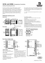
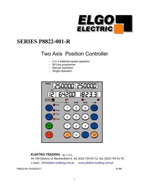
<strong>SERIES</strong> <strong>P8822</strong>-<strong>001</strong>-R<br />
Two Axis Position Controller<br />
− 2 or 3 switched <strong>sp</strong>eed operation<br />
− 99 Line programme<br />
− Manual Operation<br />
− Single Operation<br />
<strong>P8822</strong><br />
NR.<br />
mm<br />
ELGO<br />
ELECTRIC<br />
> > ><br />
Hand<br />
Single<br />
Hand<br />
Single<br />
7<br />
8 9 NR<br />
Prog<br />
Prog<br />
P-End<br />
4<br />
5 6 ><br />
Start<br />
1<br />
2 3 E<br />
Stop<br />
C 0 T R<br />
Preliminary manual !<br />
ELEKTRO-TRADING <strong>sp</strong>. z o.o.<br />
44-109 Gliwice, ul. Mechaników 9, tel. (032) 734-55-72, fax. (032) 734-55-70<br />
e-mail: et@elektro-trading.com.pl www.elektro-trading.com.pl<br />
<strong>P8822</strong>-<strong>001</strong>-SV002V0-7 41/99<br />
1
INDEX<br />
Page<br />
1. General 3<br />
1.1 Principles of operation 3<br />
1.2 Method of operation 4<br />
2.0 Features & Functions 5<br />
2.1 Bi-directional control 5<br />
2.2 Backlash compensation 6<br />
2.3 Stop offset and positioning accuracy 6<br />
2.4 Automatic stop-offset calculation 7<br />
2.5 Tolerance window (error blanking) 8<br />
2.6 Automatic retract 8<br />
2.7 Datum function 9<br />
2.8 Manual datum 9<br />
2.9 T<strong>oo</strong>l offset compensation 9<br />
2.10 Incremental error compensation 9<br />
2.11 Double start input 10<br />
2.12 Inch/metric selection 10<br />
2.13 Decimal point 10<br />
2.14 Encoder multiplication factor 10<br />
2.15 Software limits 11<br />
2.16 Two axis position comparator 11<br />
2.17 Encoder pulse monitoring 11<br />
2.18 Fault Monitoring 12<br />
3 Controller in Operation 13<br />
3.1 Programming 14<br />
3.2 Programme memory 14<br />
3.3 Checking of programme 14<br />
3.4 Editing in operation 14<br />
3.5 Programme in operation 15<br />
3.6 Operating with "fixed" programmes 15<br />
3.7 Single operation 15<br />
3.8 Manual operation 16<br />
3.9 Memory on power down 16<br />
3.10 Locking out Keypad 16<br />
4. Testing, Monitoring & Setting up 17<br />
4.1 Setting of Registers 17<br />
4.2 Default values for Registers 18<br />
5. Parameter list 19<br />
6. Description of Parameters 20-26<br />
7. Terminal layout 27-28<br />
8. Technical Data 29<br />
9. Setting and commissioning 30<br />
2
THE <strong>P8822</strong>-<strong>001</strong>-R CONTROLLER<br />
1. GENERAL<br />
The <strong>P8822</strong> controller has been supplied for a number of years and during this time many features<br />
have been added to suit particular customers. Most of these features are advantageous to most<br />
customers, consequently Elgo Electric has now incorporated all the features in one standard<br />
software.<br />
All units with this software have the following designation on the outside of the enclosure and also<br />
on the surface of the EPROM.<br />
<strong>P8822</strong>-<strong>001</strong>SV002V0-7<br />
1.1 Principles of Operation<br />
update number<br />
The <strong>P8822</strong> Controller is designed to Operate with 2 or 3 <strong>sp</strong>eed reversing drives, on the basis of<br />
fast/slow/stop. There is also optional module for analogue output for servo-motor available.<br />
The controller outputs can be selected to operate<br />
Forward and Reverse contactors<br />
Run and Reverse for Inverter systems<br />
Independent fast & slow, forward & reverse contactors for 2 and 3 <strong>sp</strong>eed motors.<br />
Position is monitored by means of an incremental Encoder. The outputs are transistors or relays.<br />
(R- Version) Inputs are NPN or PNP. The power supply unit is integrated. The controller can be<br />
used to position machinery to any desired absolute position.<br />
In this manual, the Registers are designated e.g. R1 to R99.In the X Axis di<strong>sp</strong>lay the parameters of<br />
the X Axis are di<strong>sp</strong>layed. In the Y- Axis di<strong>sp</strong>lay the parameters of Y- Axis are di<strong>sp</strong>layed. If the<br />
function of the register is commune for X and Y Axis only X- Axis window is used.<br />
3
1.2 Method of Operation<br />
The <strong>P8822</strong> controller has the following features:<br />
Absolute positioning mode<br />
Incremental positioning in forward an backward direction<br />
T<strong>oo</strong>l offset compensation in incremental mode<br />
Operation in programme mode<br />
Operation in manual mode<br />
Operation in single positioning mode<br />
Position reached output<br />
Inch/metric selection<br />
Flexible multiplier for encoder calibration<br />
Datum pre-set<br />
Automatic retract<br />
Tolerance window blanking<br />
Unidirectional approach to position for backlash elimination<br />
Encoder and drive failure detection<br />
Maximum Encoder frequency 20 kHz<br />
Memory on power down of actual Position and programme<br />
The <strong>P8822</strong> controller is very flexible and can be used in many applications. Depending on the<br />
application, the controller can be set to operate in a different way. To enable the customer to<br />
ch<strong>oo</strong>se the features he requires, we clearly describe all the features individually and how to select<br />
them. All the features are selected by means of Registers. The Registers are locked by means of a<br />
security code.<br />
Having set the registers, the operator uses the Keypad to programme length data only.<br />
4
2. FEATURES & FUNCTIONS<br />
Two <strong>sp</strong>eed operation<br />
The positioning is effected using a two <strong>sp</strong>eed drive.<br />
Fast (and slow)<br />
creep<br />
demand position<br />
stop offset<br />
slow point<br />
R 3X/Y<br />
R 1X/Y<br />
Three <strong>sp</strong>eed operation<br />
fast<br />
slow<br />
creep<br />
demand position<br />
stop offset<br />
creep point<br />
slow point<br />
R 3<br />
R 2<br />
R 1<br />
The actual position of the axis is di<strong>sp</strong>layed at all times and the demanded position is entered in the<br />
bottom di<strong>sp</strong>lay. When start is pressed, the controller calculates the difference between the two<br />
dimensions and sets the outputs to give the desired direction and <strong>sp</strong>eed, to move towards the<br />
desired position.<br />
If the distance is greater than the value set in Register R1 X/Y) the drive will first set off at high<br />
<strong>sp</strong>eed. As it reaches a distance from its destination equal to R1 X/Y it will drop out the high <strong>sp</strong>eed<br />
signal and the drive will drop to its low <strong>sp</strong>eed.<br />
It is essential that (R1/2 X/Y ) is set such that the slow <strong>sp</strong>eed is steady, before the stop signal is<br />
given. This is set during commissioning and is not a critical value. The controller will never operate<br />
correctly, if the slow down distance is t<strong>oo</strong> short.<br />
It will now run at the slow <strong>sp</strong>eed until it reaches a distance away from the destination, equal to<br />
value R3 X/Y. It will now drop out in its run signal and the drive stops.<br />
The setting of R3 X/Y is such that it is equal to a consistent overrun distance and hence the<br />
machine should stop exactly in position, within +/- 1 bit (normally +/- 0.1mm).<br />
2.1 Bi-directional control<br />
This controller operates outputs that select direction of rotation of the motor. There are a number of<br />
ways to configure the outputs to suit the type of motor being used. These outputs are tied in with<br />
the two <strong>sp</strong>eed selection. Register R8/5 is used to set the appropriate output. Ten modes are<br />
programmable.<br />
NB For General use, the terms "forward" and "reverse" have the following meaning.<br />
Forward - Machine moves away from zero in a positive direction ”count up”<br />
Reverse - Machine moves towards zero from a positive dimension “count down”<br />
These terms should not be confused on site with machinery nomenclature e.g.. a Backgauge<br />
moves towards operator and this is termed "forwards".<br />
5
2.2 Backlash Compensation<br />
The <strong>P8822</strong> controller is quite suitable for operation with mechanics having backlash, e.g. backlash<br />
in screw. To ensure that correct positioning is achieved, when backlash is present, unidirectional<br />
approach to position can be selected, by means of Register R8/6 X/Y.<br />
The distance of overrun is set in Register R4 X/Y. This must be far enough to ensure full take up of<br />
backlash and not t<strong>oo</strong> long to make positioning ponderous. It is essential that the value in this<br />
register is greater than the stop offset register R3 X/Y. When the machine stops at the end of its<br />
overrun, it is usually desirable to have a short delay. The time is set in Register R10 X/Y. The<br />
time would normally be set to a value to ensure that motor has come to rest, before opposite<br />
direction start is again made, e.g. to avoid plugging of an ac motor. Backlash Compensation is<br />
never used in incremental mode.<br />
Value 0<br />
Value 1<br />
Value 2<br />
No backlash compensation<br />
Machine goes directly to position from either direction<br />
Negative backlash<br />
When positioning, the last move is in direction away from zero, i.e. if a "smaller"<br />
dimension is selected, controller overruns in direction of zero, before reversing<br />
and making final move to position.<br />
Positive backlash<br />
When positioning, the last move is in direction towards zero, i.e. if a larger<br />
dimension is selected, controller overruns in direction away from zero, before<br />
reversing and making final move to position.<br />
2.3 Stop Offset and Positioning Accuracy<br />
When a stop signal is issued by the controller, the machine does not stop instantly. It overruns a<br />
certain distance depending on friction and inertia and whether a brake is used or not. Providing a<br />
<strong>sp</strong>eed low enough is used, this overrun will be consistent at all positions. It is therefore possible to<br />
issue the stop signal that distance before demanded position. If this is done, stopping accuracy of<br />
+/- 0.1 mm can be achieved. In the first instance, when starting commissioning, the register R3 X/Y<br />
is set to zero and overrun noted at various positions. The average value is then set into R3 X/Y<br />
and the machine will now stop within +/- 0.1 mm of demanded position.<br />
6
2.4 Automatic Stop Offset Calculation and Positioning Retry<br />
The automatic stop offset calculation and positioning retry function provides a consistently better<br />
accuracy. If a fixed stop offset is set in the controller, it gives the desired accuracy at the time of<br />
setting. It has however, been found that four things upset the settings<br />
L<strong>oo</strong>sening up of the machine, from its new state, i.e. the overrun increases.<br />
Friction being different at different points in a slideway.<br />
Wear of brakes where fitted.<br />
T<strong>oo</strong> high low <strong>sp</strong>eeds cause inconsistent accuracy.<br />
This results in machine going out of tolerance after delivery to site. Elgo Electric have incorporated<br />
automatic calculation of the stop offset. This works in conjunction with the tolerance window. When<br />
the machine reaches position, the controller checks whether the position is within tolerance. If<br />
it is not, it will recalculate the stop offset required to make it stop within tolerance on the next move.<br />
e.g. Desired position 200.0 mm<br />
Stop Offset (R3)<br />
0.2 mm<br />
Tolerance Window (R12) 0.1 mm<br />
Actual Position Reached 200.2 mm<br />
This means that the Stop Offset should be 0.4 mm. The controller notes that the actual<br />
position is outside the tolerance (199.9 to 200.1) and changes the value of the Register R3 X/Y to<br />
0.4. If the machine should now position with the new stop offset. This would mean that the final<br />
position would be within +/- 0.1 mm. Here Elgo has added the feature of automatic retry<br />
positioning. This is set by register R73 X/Y. If the value of R73 X/Y is set to zero, the controller will<br />
operate without recalculation and without retry. If the value of R73 X/Y is set to "1" this means that<br />
should the position reached be outside the tolerance window, the controller will recalculate the new<br />
stop offset. Then the machine will automatically move back a distance (the pre-set Backlash value)<br />
and reposition using the new value in R3 X/Y. It should then position <strong>sp</strong>ot on or at worst within 0.1<br />
mm once more. The number of retrys may be set higher but it is not really practical to work with a<br />
value higher than 3 (i.e. 2 retrys). If the machine cannot make its desired position within tolerance<br />
in three goes (first and two retrys ) then there is something wrong. The value of stop offset, R3 X/Y,<br />
should only need a limited range under normal operating conditions.<br />
It is also possible to use single (high) <strong>sp</strong>eed motors and with one retry get accuracy of +/- 0.1 mm,<br />
where previously a two <strong>sp</strong>eed system would have been required. This could mean the saving in<br />
cost of an inverter for instance. When using the automatic retry system, it is necessary to set the<br />
tolerance window at least 0.1 mm<br />
For automatic recalculation of stop offset, it is essential that the machine is at complete standstill,<br />
when the calculation takes place. The timer R9 X/Y (normally width of in-position pulse) has a dual<br />
role. The time delay after stop is initiated, before calculation takes place is also equal to value set<br />
in R9 X/Y. Therefore ensure that R9 X/Y is set long enough.<br />
The retry sequence is inoperative on incremental moves.<br />
7
2.5 Tolerance Window (Error blanking)<br />
De<strong>sp</strong>ite the lact that accuracy of +/- 0.1 mm is achievable, the actual value di<strong>sp</strong>lay shows the error<br />
e.g. demanded position 200.0 actual position 199.9. This sometimes worries the operator. It is<br />
possible to enter a value into Register R12 X/Y which represents an acceptable tolerance e.g. 0.1<br />
mm. When the actual position is within the tolerance window, the actual position di<strong>sp</strong>layed is<br />
made equal to the demanded position. The actual error is not lost, as the controller knows the true<br />
position. This is a useful feature, where errors of greater than 0.1 mm are acceptable e.g.. +/-<br />
0.1mm. By setting R12 X/Y to 0.5 mm, the actual di<strong>sp</strong>lay may be manipulated to read 200.0 when<br />
the actual position is between 199.5 to 200.5. This means that a "high" low <strong>sp</strong>eed or even a single<br />
"high" <strong>sp</strong>eed motor can be used, saving money, if accuracy is not critical. Tolerance window should<br />
only be used for absolute positioning, as only then it is meaningful to operator.<br />
2.6 Automatic Retract and Positioning to fixed value<br />
Some processes require the machine to move to a different position temporarily, whilst another part<br />
of the process is taking place. This would be used for example an a sheet metal Bender, where the<br />
Backstop has to Retract (move to a higher count value) whilst the bend is taking place.<br />
There are three modes selectable by Register R18/2 X/Y<br />
Value 0 : The machine retracts the distance as set in Register R5 X/Y<br />
Value 1 : The Machine moves to an absolute position set in register R5 X/Y<br />
Value 2 : The machine retracts for a time set on R10 X/Y whilst input is activated.<br />
Select Value = 0 in register R18/2 X/Y. Closing contact ST.3/6 (ST.8/6), causes the axis to retract<br />
the value set in R5 X/Y. Closing this contact again, returns axis to the original position.<br />
Select value = 1 in register R18/2 X/Y and "0" in Register R5 X/Y. Each time ST.3/6(ST.8/6) is<br />
activated, the axis will now go to zero position. R5 X/Y can be set to any desired value.<br />
Select value = 2 in register R18/2. When ST.3/6 (ST8/6) is activated, the machine retracts at slow<br />
<strong>sp</strong>eed for a time as set in Register R10 X/Y, on release of input, machine returns to original<br />
position.<br />
8
2.7 Datum Function<br />
The setting of datum needs in principle only to be carried out once during commissioning, since the<br />
actual positions are always remembered on power down.<br />
The <strong>P8822</strong> controller provides the possibility of setting the datum when operating in Absolute mode<br />
in four distinct ways. The selection of method to be used is made in Register R8/3 X/Y.<br />
Setting a value 0, 1, 2 or 3 gives the mode. Setting 0/1 and 3 applies to manual and value 2 to<br />
automatic.<br />
2.8 Manual Datum<br />
Select Value = 0 in register R8/3 X/Y<br />
Datum is achieved by closing the relevant input ST.3/4 (ST8/4). This should normally be an<br />
external keys-witch, which can only be operated by an authorised person. Closing the input,<br />
transfers the value of R7 X/Y into the actual di<strong>sp</strong>lay. This would normally be used with an axis<br />
which can be run into a fixed stop, whose absolute position is known.<br />
Select Value = 1 in register R8/3 X/Y<br />
Putting each axis in turn into position, measuring that position and entering the value into actual<br />
value di<strong>sp</strong>lay. Closing the input transfers the value in the "demand" window ("Single" mode must be<br />
selected) into the actual value di<strong>sp</strong>lay. This is useful in applications when a random position<br />
measurement can be readily made. Select axis required with ">" button.<br />
Select Value = 3 in register R8/3 X/Y<br />
This mode does not require any external Key-switch. Access Register R7 X/Y. Type in actual<br />
position. Press E. Value is transferred to actual value di<strong>sp</strong>lay and controller automatically resets to<br />
operation mode.<br />
2.9 T<strong>oo</strong>l Offset Compensation<br />
When moving in incremental, it is often the case that the subsequent function is a cut that removes<br />
part of the material e.g. Saw Blade. The finished product ends up the other side of the blade.<br />
Thus to cut the pre-set lengths, it is necessary to move the demanded distance plus the " T<strong>oo</strong>l<br />
offset". The t<strong>oo</strong>l offset, or Saw blade width is set in register R6 X/Y. This is used in all forms of<br />
incremental operation.<br />
2.10 Incremental Error compensation<br />
The basic accuracy of the control system is +/- 0.1 mm. This applies to each move. In absolute<br />
positioning mode, each position will only ever be 0.1 mm out from the absolute position. In<br />
increment-mode however, each move could be +/- 0.1 mm out. This means that relative absolute<br />
position can be cumulatively out. When feeding material though a process this is not a problem,<br />
since it is the cut product that is important and each part can only be +/- 0.1 mm out. No<br />
compensation is desirable. However, if say a series of bends is being made in a sheet of metal, it is<br />
important to hold the absolute position to +/0.1 mm. To do so " incremental error compensation"<br />
must be selected by means of register R88/6<br />
Value 0: off ( No Compensation)<br />
Value 1: on ( compensation effective )<br />
9
2.11 Double Start Input<br />
In certain applications, it may be desirable for the <strong>P8822</strong> not to restart the cycle at the end of the<br />
programme. A second start input is required before movement takes place. This feature is<br />
activated by setting R88/3 ).<br />
Value 0 : function disabled<br />
Value 1 : with double start.<br />
2.12 Inch / Metric selection<br />
The usual operating system is metric. Encoder resolution is normally chosen to match the metric<br />
resolution required. The configuration is available by means of Register R97.<br />
The actual position and registers are converted from "MM to Inch". A resolution of 0.1 mm is<br />
di<strong>sp</strong>layed as 0.004 inch<br />
NB. This does not change the dimensions stored in a programme<br />
2.13 Decimal Point<br />
The decimal point is placed in a fixed position and its optical only. It does NOT change the<br />
resolution of the system. The selected position is achieved by use of register R20 Y/Y.<br />
Value 0: No decimal place.<br />
Value 1: 1 place of decimal<br />
Value 2: 2 places of decimal<br />
Value 3: 3 places of decimal<br />
2.14 Encoder Multiplication factor<br />
In general, the encoder resolution is chosen so that 1 pulse equals 0.1 mm, 0.01 mm or 1 mm. It is<br />
not strictly necessary to do this, as a flexible multiplier is available in register R96 X/Y, to multiply<br />
encoder pulses by any value in the range from 0.00<strong>001</strong> to 9.99999<br />
This multiplication factor also acts on the register values so that all dimensions are "real" values.<br />
One point to note is that if a value greater that 1 is set, then the minimum increments in the di<strong>sp</strong>lay<br />
go up. e.g. if the multiplier is set to "2", then the position counting will be 0,2,4,6 etc. To avoid this, it<br />
is possible to utilise the encoder pulse edge counting multiplier of X2 or X4 set by setting<br />
parameter R56 X/Y NB. It is essential that the encoder does not exceed 20kHz.<br />
10
2.15 Software Limits<br />
When working in absolute mode, there are limits of movement at both ends. It is always essential<br />
to have mechanical end limit switches on a machine, for safety purposes. When such switches<br />
operate, they can cause problems in resetting the machine, and should operate only when<br />
something has seriously gone wrong with the machine. It is desirable to ensure that the operator<br />
does not try to move to position that will operate these switches. For this purpose, software limits<br />
are available and programmed in register R13 X/Y) ( minimum ) and R14 X/Y ( maximum ) Should<br />
programmed values exceed these values, pressing start will not allow movement to take place<br />
2.16 Two axis position comparator<br />
When the <strong>P8822</strong> is used in some applications, it is essential to monitor the relative positions of the<br />
2 axes. Two modes are required.<br />
Anti collision control<br />
If two Heads are on the same slide-way, it is essential that they do not reach. > Hence it is<br />
necessary to set a minimum dimension between them.<br />
Balance control<br />
If two screws are lifting a Beam, it is essential that both ends are at same height. If there is a<br />
difference between them, both must stop. This control is effected with Register R80 and R81.<br />
Setting R80: Value 0 : Checking mode inoperative<br />
Value 1 : Anti-collision operation: Controller checks both positions whilst running and if distance<br />
is less than value set in R81, stop is activated and ERROR09 info is activated.<br />
Value 2 : Skew Detection : Controller checks both positions whilst running and if difference is<br />
more than value set in R81, stop is activated and ERROR10 info is activated<br />
Setting of R81: This is the value used to compare positions of the 2 axes, in accordance with<br />
configuration of R80.<br />
2.17 Encoder Pulse monitoring<br />
There are a number of faults on a machine that can stop the operation i.e.<br />
Stalled motor, Controller failure, Cable failure, Encoder failure<br />
Should pulses fail to reach the controller after start has been given and before in position is<br />
reached, then one of the above faults must be present. The controller monitors the pulses at<br />
intervals set in Register R19 X/Y. If the Register R19 X/Y is set to "0", the monitoring features will<br />
be disabled. Should a failure occur, the ERROR01 is di<strong>sp</strong>layed in demand position window .<br />
11
2.19 Fault Monitoring<br />
When a fault occurs, it’s number flashes in the demand Position Di<strong>sp</strong>lay<br />
Fault number 01 = Encoder failure detection<br />
04 = Demand Position < min software limit (R13)<br />
05 = Demand Position > max software limit (R14)<br />
08 = difference between X&Y bigger (R81)<br />
09 = difference between X&Y bigger (R81)<br />
11 = Eeprom storage error<br />
13 = Program-Rom full<br />
14 = Program steps full<br />
Number of Programme lines greater than 99<br />
The fault message is cleared by pressing STOP button.<br />
12
3. CONTROLLER IN OPERATION<br />
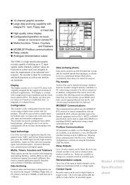
Front Panel<br />
<strong>P8822</strong><br />
NR.<br />
mm<br />
Actual position<br />
Demand position<br />
ELGO<br />
ELECTRIC<br />
> > ><br />
Hand<br />
Single<br />
Hand<br />
Single<br />
7<br />
8 9 NR<br />
Prog<br />
Prog<br />
P-End<br />
4<br />
5 6 ><br />
Start<br />
1<br />
2 3 E<br />
Stop<br />
C 0 T R<br />
Pushbuttons<br />
Prog<br />
T<br />
NR<br />
Resets the Controller. Also selects programme run mode<br />
Resets the programme to beginning. Also used to finish editing.<br />
Steps the programme through, line by line<br />
> Steps through field by field (rolls over from line to line as well)<br />
Single<br />
Hand<br />
E<br />
C<br />
Selects single run mode<br />
Select manual mode<br />
Ends programming (cursor light must be in "last" window)<br />
Cancels existing value<br />
13
3.1 Programming of the Controller<br />
3.2 Programme Memory<br />
There are a total of 400 address lines, which can be programmed. The number of steps in a<br />
program is up to 99. A new programme can be selected by means of Register R40.<br />
The values of digits in register R40 are 0 to 99 i.e. value "0" is the number 1 programme.<br />
NB: Register R40 is accessible without Security code.<br />
Normally, each line of programme comprises<br />
Address number<br />
Dimension X,Y<br />
retract on/off information<br />
A running programme is made up of a number of lines (or addresses). To programme, proceed as<br />
follows<br />
Press PROG<br />
Press NR 01 is di<strong>sp</strong>layed in Address<br />
Cursor LED below dimension X is di<strong>sp</strong>layed Press C<br />
Enter dimensional data<br />
Press > cursor LED moves to dimension Y<br />
Press C Clears value<br />
enter dimensional data<br />
Press > cursor LED moves to retract on/off<br />
enter retract on/off 0= off 1= on<br />
Clears value<br />
Pressing cursor again, moves the programming to the next line, i.e. Address number will increment<br />
to 02 and the second line can be programmed. When the desired number of lines have been<br />
programmed and the cursor LED is in the retract on/off field, Press E (for end).<br />
3.3 Checking a Programme<br />
Pressing T will reset programme to zero. By now repeatedly pressing "NR", the programme is<br />
di<strong>sp</strong>layed line by line and can be checked. Once the last line has been reached, pressing NR again<br />
resets programme to beginning.<br />
3.4 Editing a Programme<br />
If any line is to be edited, select this line by using NR. Use cursor button to select required axis.<br />
Press C to delete value<br />
Enter new value<br />
Press ><br />
The new value is now stored<br />
Press T to reset program to beginning<br />
14
3.5 Programme in Operation<br />
To start at beginning, press T (or Prog). All zeros are di<strong>sp</strong>layed<br />
Press Start<br />
Address Line switching<br />
The programme steps on to next line according the setting of Parameter R88/3. When the last line<br />
has been executed, di<strong>sp</strong>lay resets to all zeros and programme end signal is given. Pressing Start<br />
again repeats the process. The customer should use the end of programme signal to prevent<br />
continuous cycling, if he so desires. Programme can also be interrupted by use of the double start<br />
feature (Parameter R88/4). It is possible to start the cycle at any address line in a programme.<br />
Simply step through programme using NR to the line required, and press start. It is possible<br />
however, by using external individual axis start inputs to make individual moves of both axes.<br />
Value 0 = at position reached<br />
Value 1 = at start<br />
3.6 Operating with "Fixed" programmes<br />
Some applications are such that all 99 addresses are programmed just once and thereafter the<br />
operator simply selects the address he requires and presses start. This configuration is selected in<br />
register R8 value 4. The 99 lines of memory can be programmed by means of the Keypad.<br />
The operator now operates as follows<br />
Press NR<br />
NR di<strong>sp</strong>lay flashes<br />
Enter address required<br />
Press ><br />
Corre<strong>sp</strong>onding dimensions appear in demand windows<br />
Press Start<br />
3.7 Single Operation<br />
It is sometimes required to position to a desired position, outside the programme. Pressing "Single"<br />
selects this mode. Cursor LED illuminates in dimension di<strong>sp</strong>lay. The operator can now enter any<br />
desired dimension and press start. The single move can be either absolute or incremental Positive<br />
or Negative. (Parameter R18/3) Using the front start button, the axis selected, whose demand<br />
value has been changed will move alone. If both changed, both will move.<br />
15
3.8 Manual Operation<br />
The "manual operation" is very helpful fore initial commissioning. However, it is sometimes required<br />
to have "manual" positioning, readily accessible for operator. In such a case, in manual mode the<br />
buttons 7, 8, 9 and NR are for jogging purposes. To select manual mode press Key Single/Hand<br />
two times. To select the axis press > key.<br />
3.9 Controller testing<br />
To set up the test routines, select Register R90.<br />
Value = 1<br />
Set default parameter<br />
Default values are loaded into memory.<br />
Value = 2<br />
Memory Clear<br />
NB: It is essential that all Register values previously in use are noted so that they can be reentered<br />
after the test. The memory test takes approximately four and a half minutes to run.<br />
3.10 Memory on Power down<br />
The programme is always memorised. On switch on it resets to beginning. The actual value di<strong>sp</strong>lay<br />
is also memorised. The demand value in single is also memorised.<br />
3.11 Locking out Keypad<br />
It is often undesirable for the operator to change the programme. This can be prevented by locking<br />
out the programming function from the keypad. This is done by Register R8/5.<br />
Value 0 : Normal Keypad operation<br />
Value 1 : Programming function is disabled. Closing external input ST.3/8 enabled.<br />
Value 2 : All keypad functions disabled. Closing external input to ST.3/8 enabled.<br />
Value 3 : As value 0, but start/stop buttons disabled.<br />
Values 1 & 2 would normally be used in conjunction with the keys-witch.<br />
16
4. SETTING UP OF THE CONTROLLER<br />
4.1 Setting of Registers<br />
The Registers are protected by means of a security code. This ensures that the operator does not<br />
inadvertently change anything critical. In the X Axis window the Parameter of the X axis are<br />
di<strong>sp</strong>layed. Equivalent in the Y Axis di<strong>sp</strong>lay the value for the Y Axis. For common parameters only<br />
X axis di<strong>sp</strong>lay is used.<br />
To access Registers, proceed as follows<br />
Press PROG (i.e. reset)<br />
Press R (Address di<strong>sp</strong>lay flashes)<br />
Press C<br />
Enter 98 (98 appears in address field)<br />
Press ><br />
Enter security code 250565 (into demand X field)<br />
Press E<br />
The Registers are now unlocked and can be altered.<br />
To set Registers, proceed as follows<br />
Press PROG<br />
Press R (address di<strong>sp</strong>lay flashes)<br />
Press C<br />
Enter demand Register e.g. 10<br />
Press ><br />
Enter required value e.g. 20 (in demand X field)<br />
Press ><br />
Enter required value e.g. 25 (in demand Y field)<br />
Press E<br />
Any Register can be selected and changed in the above manner. If sequential Registers are to be<br />
set, Press NR instead of E and continue editing Register by Register Press E on completion.<br />
It is possible to run the Controller with Registers unlocked, eg having set the Stop offset Register<br />
R03, you may now execute a “Single” move and then go back to edit R03.<br />
To relock Registers, proceed as follows<br />
Press PROG<br />
Press R (address di<strong>sp</strong>lay flashes)<br />
Press C<br />
Enter 98<br />
Press ><br />
Press C<br />
Press E<br />
On completion they must be locked up to prevent inadvertent changes by operator. The<br />
Registers are automatically locked on power down.<br />
When registers are selected, the decimal point is set to the correct position for each parameter.<br />
Distance dimension Registers are programmed in "1 di<strong>sp</strong>lay bit" i.e. if one place of decimal is<br />
being used 1 bit = 0.1 mm. Time Registers are programmed in resolution 1 bit = 0.1 sec.<br />
17
Register R96 X/Y has a resolution of x . x x x x x<br />
Di<strong>sp</strong>lay 0.50000 = multiply by 0.5<br />
Di<strong>sp</strong>lay 2.30500 = multiply by 2.305<br />
Leading zeros are blanked when required and di<strong>sp</strong>layed where necessary.<br />
Viewing Registers<br />
It is not necessary to use the security code to check any value, simply<br />
Press Prog<br />
Press R<br />
Enter demand Register e.g. 6<br />
Press NR or ><br />
Value of Register is di<strong>sp</strong>layed<br />
Press E to exit.<br />
Registers without Security Code<br />
Register R6/R40/R46/R47/R98 is always accessible without security code.<br />
4.2 Default values for Registers.<br />
Due to customer inexperience, it is very easy to set Registers to values that will prevent complete<br />
operation of the <strong>P8822</strong> controller.<br />
In parameter R88/4 different default-tables can be selected.<br />
Value 0 = Elgo standard configuration<br />
Value 1 = Customer 1 setting DR<br />
Value 2 = Customer 2 setting LD<br />
Value 3 = Customer 3 setting AD<br />
To give a starting base for set up purposes, default values have been incorporated. If these values<br />
are used, it will be possible to run the machine and then move on to optimise the Registers to<br />
settings that suit the application. The selection of default Registers is done by selecting Register<br />
R90 and entering a value of "1" then pressing "E“<br />
18
5. Parameter List<br />
Register Value X Axis Value Y Axis Meaning<br />
1 Slow down 1<br />
2 Slow down 2<br />
3 Stop offset<br />
4 Backlash overrun<br />
5 Retract distance<br />
6 Saw width/ t<strong>oo</strong>l offset<br />
7 Datum value<br />
8 System Parameter 1<br />
8/1 Positioning mode<br />
8/2 Option<br />
8/3 Datum mode<br />
8/4 Memory mode<br />
8/5 Output configuration<br />
8/6 Backlash compensation mode<br />
9 In position signal 0,1sec<br />
10 Backlash dwell 0.1 sec<br />
12 Tolerance window<br />
13 Min software limit<br />
14 Max. software limit<br />
15 Software limit inhibit<br />
18 System Parameter 2<br />
18/1 Serial communication port on/off<br />
18/2 Retract mode<br />
18/3 Positioning in single mode<br />
18/4 Positioning in programme mode<br />
18/5 Keypad enabled<br />
18/6 no function<br />
19 encoder monitoring interval<br />
20 Decimal point<br />
28 System Parameter 3<br />
28/1 Front Start key mode<br />
29 Time delay for drive inhibit<br />
30 Time of programme end<br />
40 Programme block selected<br />
41 Number of lines in Prog Block 1-99<br />
46 Programme cycle pre-selection<br />
47 Programme cycle counter<br />
56 Encoder Edge Multiplication<br />
73 Stop offset calculation<br />
80 Comparator mode<br />
81 Comparator distance<br />
88/1 No function<br />
88/2 Default select<br />
88/3 Address line switching<br />
88/4 Double start at prog end<br />
88/5 Output / input version<br />
88/6 Incremental error comp.<br />
88 System parameter 3<br />
90 Service register<br />
92 Di<strong>sp</strong>lay brightness<br />
96 Multiplication set at 1.00000<br />
97 Inch/mm selection<br />
98 250565 Security code<br />
19
6. Description of Registers<br />
R01<br />
Slow <strong>sp</strong>eed distance<br />
Distance at which the controller switches from high <strong>sp</strong>eed to slow <strong>sp</strong>eed. The output high<br />
<strong>sp</strong>eed will be switched off.<br />
R02<br />
Creep <strong>sp</strong>eed distance<br />
Distance to demand position at which the controller switches from slow to creep <strong>sp</strong>eed<br />
R03<br />
Stop offset distance<br />
The overrun distance can be programmed to compensate for distance from the switch-off<br />
point of the motor to standstill. For exact positioning, the overrun distance should be very<br />
small (0.0 to 0.5 mm). Therefore the mechanical friction should be steady and the creep<br />
<strong>sp</strong>eed should be very slow.<br />
During commissioning, first set R12 to zero (to eliminate Tolerance window blanking), then<br />
set the value of R03 to 0.0 and execute a number of moves in both directions. Note the<br />
average overrun distance and then set R03 to that value. Then set R12 to suit.<br />
R04<br />
Backlash overrun<br />
To correct for screw or pinion backlash, the Demand position should be approached from<br />
one direction only. In positive direction therefore, the Demand position will be overrun by the<br />
value of R4 and driven back at creep <strong>sp</strong>eed after a time delay of R10, to the Demand<br />
position.<br />
R05<br />
Retract distance<br />
There are different modes available in the <strong>P8822</strong>, selectable by Register R18/2.<br />
If R18/2 = 0<br />
If R18/2 = 1<br />
If R18/2 = 3<br />
Retract Position = Actual + R5<br />
Retract Position = Value of R5<br />
Retract whilst input activate, return on deactivation<br />
When input St3/6 ST8/6 is activated, the slide moves to position as set in R5 but will not<br />
return to original position on release of input. (Value 1)<br />
Whilst the input St3/6 ST8/6 is held on, the slide will move to the “Retract” position. On<br />
release of input, slide will return to the original position. (Value 3)<br />
R06<br />
T<strong>oo</strong>l offset compensation<br />
This Register can be accessed without Security Code. When moving in incremental, it is<br />
often the case that the subsequent function is a cut that removes part of the material. Thus<br />
to cut the correct pre-set lengths, it is necessary to move the demanded distance plus the<br />
“T<strong>oo</strong>l Offset”. This feature is active in incremental mode.<br />
20
R07<br />
Datum<br />
This Register can be accessed without Security Code. The Datum value is stored in this<br />
Register. The value is used in different ways, in accordance with setting of P8/3 X/Y. Input<br />
St3/4 and St8/4 initiates loading.<br />
R08 System Register 1<br />
This Register sets the basic operating functions of the unit.<br />
Demand Window<br />
1 2 3 4 5 6<br />
Backlash<br />
0 = no backlash compensation<br />
1 = negative backlash comp<br />
2 = positive backlash comp<br />
Output Relay Config<br />
3 = 3 <strong>sp</strong>eed operation Elgo Standard mode<br />
7 = 2 <strong>sp</strong>eed operation independent output (LD)<br />
8 = 2 <strong>sp</strong>eed operation independent (AD)<br />
9 = 2 <strong>sp</strong>eed Run/reverse slow/fast (DR)<br />
Programme Memory<br />
0 = Sequential Programme<br />
1 = Table selection<br />
Datum<br />
0 = Datum to R7<br />
1 = Datum to Demand<br />
3 = Datum to R7 by keypad<br />
Option<br />
Type of positioning<br />
0 = Analogue positioning (Option)<br />
1 = Fast/slow/stop<br />
21
Relay Configurations 8/5<br />
These depend on setting of Register R8/5<br />
Value 3<br />
3 <strong>sp</strong>eed operation (Elgo standard)<br />
<strong>sp</strong>eeds selected by relays 3/8,4/9 Relay 5/10 sets direction reverse<br />
RELAY 2/7 3/8 4/9 5/10<br />
Creep forwards<br />
X<br />
Slow forwards X X<br />
Fast forwards X X X<br />
Creep reverse X X<br />
Slow reverse X X X<br />
Fast reverse X X X X<br />
R2/7 = Run. R3/8 = Slow & R4/9 = Fast combined with Run.<br />
Value = 7<br />
2 <strong>sp</strong>eed operation, Independent outputs for direction and <strong>sp</strong>eed<br />
RELAY 2/7 3/8 4/9 5/10<br />
Creep forwards<br />
X<br />
Slow forwards<br />
Fast forwards<br />
X<br />
Creep reverse<br />
X<br />
Slow reverse<br />
Fast reverse<br />
X<br />
Value 8<br />
2 <strong>sp</strong>eed operation Independent outputs forward and reverse<br />
Independent outputs fast and slow<br />
RELAY 2/7 3/8 4/9 5/10<br />
Creep forwards X X<br />
Slow forwards<br />
Fast forwards X X<br />
Creep reverse X X<br />
Slow reverse<br />
Fast reverse X X<br />
R2/7 = Forwards, R3/8 = Reverse R4/9 = Creep, R5/10 = Fast, combined with forward and reverse<br />
(but independent)<br />
Value 9 2 <strong>sp</strong>eed operation Speed set by Relays 3/8 & 4/9 Direction set by Relay 5/10<br />
RELAY 2/7 3/8 4/9 5/10<br />
Creep forwards X X<br />
Slow forwards<br />
Fast forwards X X<br />
Creep reverse X X X<br />
Slow reverse<br />
Fast reverse X X X<br />
R4/9 = Creep, R 5/10 = Fast (both independent)<br />
22
R09<br />
Time position reached<br />
At the end of each move, the controller gives an output, to signal “in position”. The length of<br />
this pulse is set in R9. Setting 0.0 gives a maintained output.<br />
R10<br />
Backlash dwell time<br />
When the machine stops at the end of the overrun, it is usually desirable to have a short<br />
delay. The time is set in this Register.<br />
R12<br />
Tolerance window<br />
It is possible to enter a value in Register R12 that represents an acceptable tolerance e.g.<br />
0.1 mm. When the Actual Position is within the Tolerance window, the Actual position<br />
di<strong>sp</strong>layed is made equal to the Demand position. The actual error is not lost, as the<br />
controller knows the true position.<br />
Example: R12 = 0.2<br />
Therefore tolerance window is +/- 0.2mm<br />
Di<strong>sp</strong>lay without Tolerance set<br />
Di<strong>sp</strong>lay with Tolerance set<br />
Aktual Di<strong>sp</strong>lay<br />
Demand Di<strong>sp</strong>lay<br />
R13/ R14 Min/Max software limits<br />
Demand < Limit R13 =<br />
Demand > Limit R14 =<br />
ERR04 Fault Message<br />
ERR05 Fault Message<br />
Single Operation<br />
Immediately after start signal, the controller checks the software limits. If the Demand<br />
position is greater or smaller than the corre<strong>sp</strong>onding limit, the controller will stop and show<br />
the error message on the di<strong>sp</strong>lay. The backlash distance in R4 is considered at the check of<br />
the Max software limit, if the backlash is activated in R8/6 X/Y.<br />
Hand Operation<br />
The movement will stop when software limits are reached. If moving at high <strong>sp</strong>eed, the drive<br />
will drop to creep <strong>sp</strong>eed at a distance set in R1 from this limit. This prevents running into the<br />
ends of the machine. The end limit values are modified by backlash value as set in R4, if<br />
R8/6 X/Y is selected.<br />
R15<br />
Software Limit Selection<br />
Software limits (R13 & R14) are active in accordance with the setting of R15/6<br />
xxxxx0<br />
xxxxx1<br />
xxxxx2<br />
xxxxx3<br />
Both software limits active<br />
Min software limit (R13) inhibited<br />
Max software limit (R14) inhibited<br />
Both software limits (R13&R14) inhibited<br />
23
R18 System Register 2<br />
This Register also sets the functions of the controller.<br />
Demand Window<br />
1 2 3 4 5 6<br />
Option<br />
Keyboard protection<br />
0 = Enabled<br />
1 = Programming disabled<br />
2 = All keyboard function disabled<br />
3 = Memory and start/stop disabled<br />
Positioning in Prog<br />
0 = Absolute<br />
1 = Incremental +ve<br />
2 = Incremental -ve<br />
Positioning in single<br />
0 = Absolute<br />
1 = Incremental + ve<br />
2 = Incremental – ve<br />
Retract mode<br />
0 = retract to Actual + P5 setting value<br />
1 = retract to absolute position in P5<br />
2 = retract whilst input active Return on deactivation<br />
Serial link<br />
0 = none<br />
R19<br />
Encoder monitoring<br />
If after positioning is initiated, no Encoder pulses are sensed after a time set in R19,<br />
positioning will be aborted and Fault ERROR01 will be di<strong>sp</strong>layed. Setting R19 to 0.0,<br />
disables Encoder pulse monitoring.<br />
R20<br />
Decimal Point<br />
The decimal point is placed in a fixed position and is optical only. It does not change the<br />
resolution of the system..<br />
R20 = xxxxx0 = without<br />
R20 = xxxxx1 = 1/10<br />
R20 = xxxxx2 = 1/100<br />
R20 = xxxxx3 = 1/1000<br />
24
R28 System Register 3<br />
This Register also sets the functions of the controller.<br />
Demand Window<br />
1 2 3 4 5 6<br />
Option<br />
0 = Front-panel Start X and Y axis<br />
1 = Front panel Start only axes selected with courser<br />
R29<br />
Time Delay for Drive inhibit (Positioning)<br />
On activating start, output Positioning is activated. On arriving in position, after a time delay<br />
of R29 this output deactivates.<br />
R30<br />
Time of Program end signal<br />
If last step of program is completed, the signal program-end is activated for the time<br />
programmed in this register.<br />
R40<br />
Programme Block selection<br />
This Register can be accessed without opening Security Code in R98. The Programme<br />
Block required for operation should be entered. (0-99)<br />
R41<br />
Number of Lines in each Programme Block<br />
Enter the number of lines required per Programme Block (1 – 99). The number of Blocks<br />
will be calculated automatically.<br />
Example : Total number of Lines = 200, Number of Lines required per Block = 25<br />
(enter 25 into R41). Therefore number of Programme blocks = 8<br />
R46<br />
Program Cycle-pre selection<br />
To limit the execution of the programme the cycle counter can be set. If the Register R47<br />
(Cycle counter) is equal the pre selection the signal ready will drop off. To Disable the<br />
counter set R46 to zero.<br />
R47<br />
Program Cycle counter<br />
When the cycle counter is complete. i.e. R46 equal to R47 the output ready drop of and<br />
cycle count is di<strong>sp</strong>layed in actual position window. The external and front panel Start are<br />
disabled. To clear the output to allow positioning again R47 must be set to zero. For<br />
temporary unlock press Stop. The one more programme cycle can be done. After<br />
completing this programme new counter value is di<strong>sp</strong>layed and ready drop of again.<br />
R56<br />
Encoder Edge Multiplication<br />
1 = x1 2 = x2 4 = x4<br />
Entry of any other value will automatically select 1<br />
25
R73<br />
Automatic Stop Offset Calculation and Positioning Retry<br />
If the value of R73 X/Y is set to zero, the controller will operate without recalculation and<br />
without retry. If the value of R73 X/Y is set to "1" this means that should the position<br />
reached be outside the tolerance window, the controller will recalculate the new stop offset<br />
but no retry. If R73 is set to any value bigger than “1” the controller will also retry.<br />
R80<br />
Two axis position comparator<br />
Two modes are required. Anti collision control and Balance control<br />
Setting R80: Value 0 : Checking mode inoperative<br />
Value 1 : Anti-collision operation.<br />
Value 2 : Skew Detection<br />
R81<br />
Comparator distance<br />
Controller checks both positions whilst running and if difference is bigger than value set in<br />
R81, stop is activated and ERROR09/ERROR10 info is activated.<br />
R88 System Register 4<br />
This Register sets further basic functions of the controller.<br />
Demand Window<br />
1 2 3 4 5 6<br />
Incremental error comp<br />
0 = not active<br />
1 = active<br />
Output / Input Version<br />
0 = D-Sub connector<br />
1 = Relays output / Ria type input<br />
Double start at Prog end<br />
0 = without<br />
1 = with<br />
Address Line switching<br />
0 = at position reached<br />
1 = at start<br />
2 = at position reached (Reset to Line 1 at prog end)<br />
Default selection<br />
0 = Elgo standard (EL)<br />
1 = Customer 1 (DR)<br />
2 = Customer 2 (LD)<br />
3 = Customer 3 (AD)<br />
Option<br />
26
R90 Service register<br />
Only active when P98 is unlocked. Select button as shown below:<br />
Button 1 - Pressing this button loads default values into all Parameters<br />
Button 2 – Clear memory<br />
R92 Di<strong>sp</strong>lay brightness<br />
With the setting of this Parameter, the brightness of the di<strong>sp</strong>lay can be altered.<br />
0.0 = dark, 9.9 = max brightness.<br />
R96<br />
Encoder Pulse Multiplier<br />
A factor (0.00<strong>001</strong> to 9.9999) can be entered in this Register. The incoming pulses will be<br />
multiplied by this factor, to manipulate the di<strong>sp</strong>lay to required dimensions. If no<br />
multiplication is required, this Register must be set to 1.00000.<br />
R97<br />
Inch/ MM selection<br />
This Register sets the metric ore inch mode. The register setting has priority to the external<br />
selection of the input. Active in AD and LD default.<br />
Demand Window<br />
1 2 3 4 5 6<br />
Option<br />
0 = mm mode<br />
1 = Inch mode 0,<strong>001</strong> inch resolution<br />
R98<br />
Security Code<br />
Enter 250565 to unlock and change Parameters<br />
27
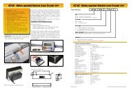
7. Terminal layout <strong>P8822</strong>-<strong>001</strong>-R<br />
ST9<br />
1<br />
2<br />
3<br />
FUSE 0,4A<br />
1<br />
2<br />
3<br />
4<br />
5<br />
6<br />
7<br />
8<br />
9<br />
10<br />
1<br />
2<br />
3<br />
4<br />
5<br />
6<br />
7<br />
8<br />
9<br />
10<br />
ST4 ST6<br />
ST1<br />
1<br />
6<br />
9<br />
5<br />
ST2<br />
1<br />
6<br />
9<br />
5<br />
ST3<br />
1<br />
2<br />
3<br />
4<br />
5<br />
6<br />
7<br />
8<br />
ST8<br />
1<br />
2<br />
3<br />
4<br />
5<br />
6<br />
7<br />
8<br />
ST 4 Output Relays 1-5 X<br />
PIN Configure 3 (EL) Configure 7 (LD) Configure 8 (AD) Configure 9 (DR) Relays<br />
1 - 2 Axes in position Axes in position Axes in position Axes in position R1<br />
3 – 4 Run X Creep reverse X Forward X Run X R2<br />
5 – 6 Slow X Creep forward X Reverse X Reverse X R3<br />
7 – 8 Fast X Fast reverse X Slow X Slow X R4<br />
9 - 10 Reverse X Fast forward X Fast X Fast X R5<br />
ST 6 Output Relays 6-10 Y<br />
PIN Configure 3 (EL) Configure 7 (LD) Configure 8 (AD) Configure 9 (DR) Relays<br />
1 - 2 Ready X+Y Positioning Ready X+Y Ready X+Y R6<br />
3 – 4 Run Y Creep reverse Y Forward Y Run Y R7<br />
5 – 6 Slow Y Creep forward Y Reverse Y Reverse Y R8<br />
7 – 8 Fast Y Fast reverse Y Slow Y Slow Y R9<br />
9 - 10 Reverse Y Fast forward Y Fast Y Fast Y R10<br />
ST 3 Input signals<br />
PIN Standard 0 (EL) Customer 2 (LD) Customer 3 (AD) Customer 1 (DR)<br />
1 0 Volt 0 Volt 0 Volt 0 Volt<br />
2 Start X/Y NC Start X/Y Start X/Y<br />
3 Stop X/Y Stop X/Y Stop X/Y Stop X/Y<br />
4 Datum X Datum X Datum X Datum X<br />
5 Inch/mm X/Y NC Inch/mm X/Y Inch/mm X/Y<br />
6 Retract X Retract X Retract X Retract X<br />
7 Cycle counter Sequential start Cycle counter NC<br />
8 Write enable Write enable Write enable Write enable<br />
28
ST 8 Input signal<br />
PIN Standard 0 (EL) Customer 2 (LD) Customer 3 (AD) Customer 1 (DR)<br />
1 0 Volt 0 Volt 0 Volt 0 Volt<br />
2 NC NC NC NC<br />
3 NC NC NC NC<br />
4 Datum Y Datum Y Datum Y Datum Y<br />
5 Start X NC Start X Start X<br />
6 Retract Y Retract Y Retract Y Retract Y<br />
7 NC NC NC NC<br />
8 Start Y NC Start Y Start Y<br />
ST 1/2 Encoder Input<br />
PIN<br />
FUNCTION<br />
1 0 V<br />
2 +24 VDC<br />
3 A Channel<br />
4 B Channel<br />
5 Screen<br />
8 Maker pulse<br />
ST 9 Power supply<br />
PIN<br />
FUNCTION<br />
1 115VAC/230 VAC<br />
2 115VAC/230 VAC<br />
3 Earth PE<br />
29
8. Technical Data<br />
Power Supply 230/115 VAC +/-15%<br />
Consumption<br />
Encoder supply<br />
Input Signals<br />
Outputs<br />
Memory<br />
Connectors<br />
Di<strong>sp</strong>lay<br />
Hardware<br />
System accuracy<br />
Count Frequency<br />
Enclosure<br />
20VA<br />
+24v dc 130 mA max<br />
NPN negative logic : connect inputs to common 0v<br />
(option PNP – if <strong>sp</strong>ecified at order stage only)<br />
minimum time of input signal : 300 ms<br />
input current : 10 mA max<br />
relay contact 250v 0.3A – suppress external coils<br />
Eeprom no Lifetime limit<br />
D-Sub<br />
7 segment LED 10 mm high<br />
16 bit microprocessor with 32K E-Prom and 16K RAM<br />
+/- 1 increment<br />
20 kHz (higher on request at order stage)<br />
ie with 0.1 mm resolution it gives 60 m/min<br />
Black metal, for fitting into control panels<br />
144W x 144H x 60D plus 30mm for connectors<br />
Cut-out 138 x 138<br />
Ambient temperature<br />
0 to +50 deg C<br />
WARNING<br />
NB All relays, contactors, solenoids, brakes etc. must be suppressed with either diodes (for dc) or<br />
RC networks (for ac). If this is not done, Elgo cannot guarantee correct operation.<br />
30
9. SETTING UP AND COMMISSIONING<br />
9.1 Installation Hints<br />
Elgo electric controllers are constructed to the latest standards of technology and protected against<br />
electrical “noise”.<br />
To enable the controller to operate successfully, the following instructions must be carried out.<br />
Location<br />
Power Supply:<br />
Cable:<br />
Screening:<br />
The unit must not be mounted in vicinity of high inductive or<br />
capacitive powers or static electricity.<br />
For 230v single phase supply, avoid using the same feed as to motors or<br />
contactors. Otherwise fit a Filter.<br />
All low voltage cables must be run separately from power cables.<br />
All external signal cables must be screened<br />
1.Encoder cable<br />
2.Input signal cable<br />
3.Output signal cables<br />
4.Power Supply dc cables<br />
5.Analogue signal cables<br />
All screens must be connected to a common earth point,. Only at one side. (Controller side)<br />
NB: Do not connect zero line to earth<br />
Suppression:<br />
To avoid electronic noise. Suppress all coils in the cabinet and on<br />
Machine.<br />
1. RC network for ac coils (e.g. 0.1 micro F+ 100 ohms)<br />
2. Freewheel diode for dc coils<br />
3. RC or similar suppresser for motor power lines and Brakes.<br />
31
10. Ordering Codes<br />
P 88 2 2 – 000- 230 –XY – R-EN-XXX<br />
P = Position Controller<br />
Series<br />
<strong>P8822</strong> with Programme memory<br />
Programme Memory<br />
1 = none<br />
2 = with<br />
Number of Axes<br />
Construction<br />
000 = standard<br />
<strong>001</strong> = 1 st <strong>sp</strong>ecial version<br />
etc<br />
Supply voltage<br />
024 = 24 V DC<br />
115 = 115 V AC<br />
230 = 230 V AC<br />
Encoder input<br />
0 = A/B 24V/24V 20KHz PNP<br />
1 = A/B/0 24V24V 20KHz PNP<br />
* 2 = 5 V line receiver<br />
* 3 = 5V line receiver with index input<br />
8 = A/B 24V /24 neg. logic NPN<br />
Special Features<br />
* P = Analogue closed l<strong>oo</strong>p for X axes<br />
R = Relay output<br />
EN = input NPN<br />
* S= Serial communication link RS232<br />
*under construction<br />
32