Metal Orifice Assemblies - O'Keefe Controls Inc
Metal Orifice Assemblies - O'Keefe Controls Inc
Metal Orifice Assemblies - O'Keefe Controls Inc

Create successful ePaper yourself
Turn your PDF publications into a flip-book with our unique Google optimized e-Paper software.
2<br />
Table of Contents<br />
®<br />
®<br />
Page<br />
Sapphire <strong>Orifice</strong> <strong>Assemblies</strong> ......................................................................................... 3-5<br />
<strong>Metal</strong> <strong>Orifice</strong> <strong>Assemblies</strong> - Barb Connections .............................................................. 6-7<br />
<strong>Metal</strong> <strong>Orifice</strong> <strong>Assemblies</strong> - NPT Connections .............................................................. 8-9<br />
<strong>Metal</strong> <strong>Orifice</strong> <strong>Assemblies</strong> - Inserts ............................................................................ 10-13<br />
<strong>Metal</strong> <strong>Orifice</strong> <strong>Assemblies</strong> - Compression Fittings .................................................... 14-15<br />
Push-on Tube Adapters ...................................................................................................16<br />
Replaceable <strong>Orifice</strong> <strong>Assemblies</strong> ......................................................................................17<br />
<strong>Metal</strong> <strong>Orifice</strong> <strong>Assemblies</strong> – Miscellaneous ............................................................... 18-19<br />
<strong>Orifice</strong> Air Flow and Water Flow Charts .................................................................. 20-24<br />
Precision Micro-<strong>Orifice</strong>s ® .0003" to .005" Diameter ............................................... 25-28<br />
Restriction <strong>Orifice</strong> Unions ...............................................................................................29<br />
<strong>Orifice</strong> Kits ................................................................................................................ 30-31<br />
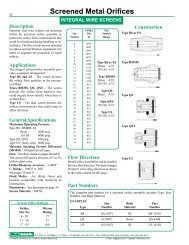
Screened <strong>Orifice</strong>s - Integral Wire Screens ................................................................ 32-37<br />
Miniature In-Line Screens ......................................................................................... 38-40<br />
Breathers ..........................................................................................................................41<br />
Pressure Snubbers ............................................................................................................42<br />
Fixed Flow Rate <strong>Orifice</strong>s.................................................................................................43<br />
Engineering Information - Index .....................................................................................44<br />
Fundamentals of Flow Measurement .......................................................................45<br />
Extending <strong>Orifice</strong> Flow Data ...................................................................................46<br />
Technical Considerations .........................................................................................47<br />
Choked Flow of Gases .............................................................................................48<br />
Calibrated <strong>Orifice</strong>s...........................................................................................................49<br />
Custom <strong>Orifice</strong> <strong>Assemblies</strong> .............................................................................................50<br />
Water Totalizer with Remote Readout ............................................................................51<br />
Check Valve Products<br />
Miniature Check Valves ..................................................................................... 52-55<br />
Miniature Fixed Flow <strong>Controls</strong> .......................................................................... 56-60<br />
Miniature Checked <strong>Orifice</strong>s .....................................................................................61<br />
Accessories<br />
Miniature Stainless Steel Fittings....................................................................... 62-65<br />
Miniature Brass Fittings ...........................................................................................66<br />
Regulators, Filters, Flow Instruments ......................................................................67<br />
Low Air Pressure Switches ......................................................................................68<br />
Other <strong>O'Keefe</strong> Products<br />
Pneumatic Sensors ...................................................................................................69<br />
Low Dew Point Air Dryer ........................................................................................70<br />
About <strong>O'Keefe</strong> <strong>Controls</strong> Co.............................................................................................71<br />
® Registered Trademark of <strong>O'Keefe</strong> <strong>Controls</strong> Co.<br />
See Catalog and Product Updates on our Website<br />
www.okcc.com<br />
P.O. BOX Q • TRUMBULL, CT 06611 • CT PHONE (203) 261-6711 • TOLL FREE PHONE (800) 533-3285 • FAX (203) 261-8331<br />
© O'KEEFE CONTROLS CO. • 2003 ALL RIGHTS RESERVED e-mail ca@okcc.com • website www.okcc.com<br />
5/1/03 Rev. 4
Sapphire <strong>Orifice</strong> <strong>Assemblies</strong><br />
Description<br />
The restrictors incorporate a precision synthetic sapphire orifice<br />
which is fitted within a main body. The sapphire orifice is a stable,<br />
accurate flow restrictor. Standard sizes range from .0012" to<br />
.0252" orifice diameter in 32 increments.<br />
Applications<br />
• Precision Flow Control - Gases or Liquids<br />
• Accurate Timing in Pneumatic or Hydraulic Circuits<br />
• Pressure Dividing Circuits and Pneumatic Resistance Bridges<br />
• Impedance Matching<br />
Kits<br />
See page 31 for kit selection.<br />
General Specifications<br />
Maximum Operating Pressure – 100 psig<br />
Flow Direction – Preferred direction shown below.<br />
Not recommended for reverse flow.<br />
Flow – See flow chart for air on page 22.<br />
<strong>Orifice</strong> Diameters – .0012" to .0252"<br />
<strong>Orifice</strong> Diameter Accuracy – ±.0003"<br />
C v Range – .00003 to .013 See page 22.<br />
Fluid Media – Air, Water, Gases and Liquids compatible with<br />
materials of construction.<br />
Dimensions – See drawings on page 4, 5.<br />
Construction<br />
Large<br />
Bore End<br />
Large<br />
Bore End<br />
Large<br />
Bore End<br />
Large<br />
Bore End<br />
Type A<br />
Insert<br />
Type F<br />
Type S<br />
Type L<br />
Small<br />
Bore End<br />
Small<br />
Bore End<br />
Small<br />
Bore End<br />
Small<br />
Bore End<br />
Large<br />
Bore End<br />
Large<br />
Bore End<br />
The restrictors should be installed with flow in the direction shown above. The flow<br />
data provided in this catalog is measured for the flow direction shown above.<br />
.0012" to .0252" DIA.<br />
Type A<br />
Type J, EA<br />
Type P<br />
Type SF Type BTF, BWF<br />
Type A-44FTX Type IH<br />
Type A<br />
Insert<br />
Type A<br />
Insert<br />
Type F<br />
Insert<br />
Type A-MC4<br />
Sapphire<br />
<strong>Orifice</strong><br />
Small<br />
Bore End<br />
Small<br />
Bore End<br />
Sapphire Sizes Available<br />
Size <strong>Orifice</strong> Diameter<br />
Number mm In.<br />
3 .03 .0012<br />
4 .04 .0016<br />
5 .05 .0020<br />
6 .06 .0024<br />
7 .07 .0028<br />
8 .08 .0031<br />
9 .09 .0035<br />
10 .10 .0039<br />
11 .11 .0043<br />
12 .12 .0047<br />
13 .13 .0051<br />
14 .14 .0055<br />
15 .15 .0059<br />
16 .16 .0063<br />
17 .17 .0067<br />
18 .18 .0071<br />
20 .20 .0079<br />
22 .22 .0087<br />
24 .24 .0094<br />
26 .26 .0102<br />
28 .28 .0110<br />
30 .30 .0118<br />
32 .32 .0126<br />
34 .34 .0134<br />
36 .36 .0142<br />
40 .40 .0157<br />
44 .44 .0173<br />
48 .48 .0189<br />
52 .52 .0205<br />
54 .54 .0213<br />
58 .58 .0228<br />
64 .64 .0252<br />
Part Numbers<br />
The complete part number for an orifice assembly includes Type,<br />
Size Number, Body Material and Options.<br />
EXAMPLES<br />
Size Number Body Part<br />
Type (<strong>Orifice</strong> Dia.) Material Options Number<br />
A 3 (.0012") Nylon — A-3-NY<br />
S 5 (.0020") Brass — S-5-BR<br />
S 5 (.0020") Brass EN S-5-BR-EN<br />
J 10 (.0039") Brass — J-10-BR<br />
J 10 (.0039") SS — J-10-SS<br />
Options<br />
• Electroless nickel plating is available on Type S and<br />
Type L. Add suffix EN.<br />
• Plating is for external appearance only.<br />
• See page 37 for screened orifices.<br />
(More on pages 4, 5.)<br />
3<br />
P.O. BOX Q • TRUMBULL, CT 06611 • CT PHONE (203) 261-6711 • TOLL FREE PHONE (800) 533-3285 • FAX (203) 261-8331<br />
© O'KEEFE CONTROLS CO. • 2003 ALL RIGHTS RESERVED e-mail ca@okcc.com • website www.okcc.com
4<br />
Type A<br />
Type F<br />
Type J<br />
Type EA<br />
.194"/.196" Dia.<br />
Dimensions<br />
.110" .196"<br />
.306"<br />
Sapphire <strong>Orifice</strong> <strong>Assemblies</strong><br />
1/8" NPT - both ends<br />
7/16" HEX<br />
.970"<br />
1/4" NPT - Both Ends<br />
9/16" HEX<br />
1.38"<br />
Press Fit Into Bore<br />
.125"/.126" Dia.<br />
.128"/.129" Dia.<br />
.134"/.137" Dia.<br />
.0012" to .0252" DIA.<br />
Specifications<br />
PLASTIC INSERT<br />
Body – Nylon<br />
<strong>Orifice</strong> – Synthetic Sapphire<br />
Press fits into bore – .125"/.126"<br />
Standard <strong>Orifice</strong> Sizes – .0012" to .0252" Dia.<br />
PLASTIC INSERT<br />
Body – Nylon<br />
<strong>Orifice</strong> – Synthetic Sapphire<br />
Press fits into bore – .132"/.133"<br />
Fits into tubing – 1/8" ID Flexible Plastic<br />
Standard <strong>Orifice</strong> Sizes – .0012" to .0252" Dia.<br />
HEX NIPPLE<br />
Body – Brass or 303 SS<br />
Insert – Nylon<br />
<strong>Orifice</strong> – Synthetic Sapphire<br />
Threads – 1/8" NPT<br />
Standard <strong>Orifice</strong> Sizes – .0012" to .0252" Dia.<br />
HEX NIPPLE<br />
Body – Brass or 303 SS<br />
Insert – Nylon<br />
<strong>Orifice</strong> – Synthetic Sapphire<br />
Threads – 1/4" NPT<br />
Standard <strong>Orifice</strong> Sizes – .0012" to .0252" Dia.<br />
Type L<br />
Type S<br />
Type SF<br />
10-32 Straight Thread<br />
Seal<br />
1/4" HEX<br />
.530"<br />
Barb for 1/16" or 3/32"<br />
ID Tubing Both Ends<br />
3/16" HEX<br />
9/16"<br />
Barb for 1/16" ID Tubing<br />
Both Ends<br />
3/16" HEX<br />
9/16"<br />
Barb for 1/16" ID<br />
Tubing<br />
ADAPTER<br />
Body – Brass Seal – Viton<br />
<strong>Orifice</strong> – Synthetic Sapphire<br />
Thread – 10-32 UNF<br />
Barb – For 1/16" ID Tubing<br />
Option – Electroless nickel plating on brass<br />
Standard <strong>Orifice</strong> Sizes – .0012" to .0252" Dia.<br />
DUAL BARB<br />
Body – Brass<br />
<strong>Orifice</strong> – Synthetic Sapphire<br />
Barb – For 1/16" or 3/32" ID Tubing<br />
Option – Electroless nickel plating on brass<br />
Standard <strong>Orifice</strong> Sizes – .0012" to .0252" Dia.<br />
DUAL BARB<br />
Body – Brass<br />
<strong>Orifice</strong> – Synthetic Sapphire<br />
Barb – For 1/16" ID Tubing<br />
Standard <strong>Orifice</strong> Sizes – .0012" to .0252" Dia.<br />
(More on page 5.)<br />
P.O. BOX Q • TRUMBULL, CT 06611 • CT PHONE (203) 261-6711 • TOLL FREE PHONE (800) 533-3285 • FAX (203) 261-8331<br />
© O'KEEFE CONTROLS CO. • 2003 ALL RIGHTS RESERVED e-mail ca@okcc.com • website www.okcc.com
Type P<br />
Type IH<br />
Type BTF<br />
Type BWF<br />
Dimensions<br />
Sapphire <strong>Orifice</strong> <strong>Assemblies</strong><br />
10-32 Straight Thread<br />
Seal<br />
1/4" HEX<br />
9/32"<br />
.080"<br />
1/8" NPT<br />
.875"<br />
No Connection<br />
This End<br />
.0995"<br />
.1000" Dia.<br />
7/16" HEX<br />
Barb for<br />
1/16" ID<br />
Tubing<br />
Barb for 1/8"<br />
ID Tubing<br />
.940"<br />
9/16" HEX<br />
1/8" NPT<br />
.0012" to .0252" Dia.<br />
Specifications<br />
BLEED PLUG<br />
Body – Brass Seal – Viton<br />
<strong>Orifice</strong> – Synthetic Sapphire<br />
Maximum Operating Pressure – 100 psig<br />
Thread – 10-32 UNF<br />
Standard <strong>Orifice</strong> Sizes – .0012" to .0252" Dia.<br />
INSERT<br />
Materials<br />
Body – Brass or 303 SS<br />
<strong>Orifice</strong> – Synthetic Sapphire<br />
Maximum Operating Pressure – 100 psig<br />
Press Fit – presses into .0980"/.0990" Dia.<br />
<strong>Orifice</strong> Sizes – .0012" to .0252" Dia.<br />
ADAPTER<br />
Materials<br />
Body – Brass or 303 SS<br />
<strong>Orifice</strong> – Sapphire/Nylon Sleeve<br />
Maximum Operating Pressure – 100 psig<br />
Connections – 1/8" NPT x 1/16" Barb<br />
<strong>Orifice</strong> Sizes – .0012" to .0252" Dia.<br />
ADAPTER<br />
Materials<br />
Body – Brass or 303 SS<br />
<strong>Orifice</strong> – Sapphire/Nylon Sleeve<br />
Maximum Operating Pressure – 100 psig<br />
Connections – 1/8" NPT x 1/8" Barb<br />
<strong>Orifice</strong> Sizes – .0012" to .0252" Dia.<br />
5<br />
Type A-44FTX<br />
1/4" NPT 9/16" HEX<br />
#4 SAE<br />
37° FLARE<br />
7/16" - 20 TH'D<br />
1.42"<br />
37° FLARED TUBE CONNECTOR<br />
Body – Brass or 304 SS<br />
<strong>Orifice</strong> – Sapphire/Nylon Sleeve<br />
Maximum Operating Pressure – 200 psig<br />
Maximum Pressure Differential – 100 psi<br />
<strong>Orifice</strong> Sizes – .0012" to .0252" Dia.<br />
Type A-MC4<br />
1.49"<br />
1/4" NPT 9/16" HEX<br />
1/4"<br />
TUBE OD<br />
TUBE ADAPTER<br />
Body – 316 SS<br />
<strong>Orifice</strong> – Sapphire/Nylon Sleeve<br />
Maximum Operating Pressure – 100 psig<br />
<strong>Orifice</strong> Sizes – .0012" to .0252" Dia.<br />
For 1/4" OD <strong>Metal</strong> Tubing<br />
Made from Swagelok Male Connector<br />
P.O. BOX Q • TRUMBULL, CT 06611 • CT PHONE (203) 261-6711 • TOLL FREE PHONE (800) 533-3285 • FAX (203) 261-8331<br />
© O'KEEFE CONTROLS CO. • 2003 ALL RIGHTS RESERVED e-mail ca@okcc.com • website www.okcc.com
6<br />
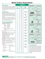
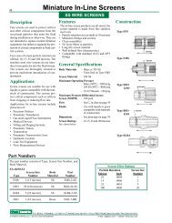
Description<br />
One-piece construction of solid metal is<br />
employed. <strong>Orifice</strong>s are accurately machined,<br />
thoroughly cleaned, and flow tested to exacting<br />
standards. Sizes range from .004" to<br />
.063" orifice diameter. Special sizes can be<br />
made to order.<br />
Applications<br />
• Precision Flow Control -<br />
Gases or Liquids<br />
• Speed <strong>Controls</strong> -<br />
Cylinders and Actuators<br />
• Accurate Timing in Pneumatic or<br />
Hydraulic Circuits<br />
• Flow Restriction<br />
• Accurate Throttling<br />
• Snubbers - Gages and Instruments<br />
Advantages<br />
• High Pressure Capability<br />
• Bi-directional Flow Compatibility<br />
• Economical Precision <strong>Orifice</strong><br />
• Repeatable <strong>Orifice</strong> Size and Shape<br />
• Predictable Flow Rate<br />
Flow Direction<br />
<strong>Metal</strong> <strong>Orifice</strong> <strong>Assemblies</strong> can be used for<br />
flow in either direction. The data on pages<br />
20 and 21 is for a flow direction as shown in<br />
the right column on this page.<br />
Kits<br />
See pages 30-31 for kit selection.<br />
General Specifications<br />
Maximum Operating Pressure – 100 psig<br />
Flow – See flow chart for air on<br />
pages 20 and 21.<br />
<strong>Orifice</strong> Diameters – .004" to .063"<br />
<strong>Orifice</strong> Diameter Accuracy – ±.0003"<br />
C v Range – .00035 to .088<br />
See pages 20 and 21.<br />
Fluid Media – Air, Water, Gases and<br />
Liquids compatible with materials of<br />
construction.<br />
Dimensions – See drawings on page 7.<br />
<strong>Metal</strong> <strong>Orifice</strong> <strong>Assemblies</strong><br />
BARB CONNECTIONS<br />
<strong>Orifice</strong> Size<br />
Size Dia. Number<br />
Number In. Range<br />
4 .0039<br />
5 .0051<br />
6 .0059 Type T<br />
7 .0071 Brass 4-35<br />
8 .0079 303 SS 4-35<br />
9 .0091<br />
10 .0102 Type W<br />
11 .0110 Brass 4-63<br />
12 .0122 303 SS 4-63<br />
13 .0130<br />
14 .0142 Type M<br />
15 .0150 Brass 4-35<br />
16 .016 303 SS 4-35<br />
17 .017<br />
18 .018 Type N<br />
19 .019 Brass 4-63<br />
20 .020 303 SS 4-63<br />
21 .021<br />
22 .022 Type Q<br />
23 .023 Brass 4-35<br />
24 .024<br />
25 .025 Type BT<br />
26 .026 Brass 4-35<br />
27 .027 303 SS 4-35<br />
28 .028<br />
29 .029 Type BW<br />
31 .031 Brass 4-63<br />
32 .032 303 SS 4-63<br />
33 .033<br />
35 .035 Type QX<br />
37 .037 Brass 4-35<br />
38 .038 303 SS 4-35<br />
39 .039<br />
40 .040 Type FM<br />
41 .041 Brass 4-63<br />
42 .042 303 SS 4-63<br />
43 .043<br />
47 .047 Type FF<br />
52 .052 Brass 4-63<br />
55 .055 303 SS 4-63<br />
60 .060<br />
63 .063<br />
Part Numbers<br />
Construction<br />
Type T or W<br />
Type M or N<br />
Type Q<br />
Type BT or BW<br />
Type QX<br />
Type FM<br />
Type FF<br />
The complete part number for an orifice assembly is composed of Type,<br />
Size Number, Body Material and Options.<br />
EXAMPLES<br />
Size Body Part<br />
Type Number Material Options Number<br />
T 4 (.004") Brass – T-4-BR<br />
BW 16 (.016") SS – BW-16-SS<br />
M 24 (.024") Brass – M-24-BR<br />
P.O. BOX Q • TRUMBULL, CT 06611 • CT PHONE (203) 261-6711 • TOLL FREE PHONE (800) 533-3285 • FAX (203) 261-8331<br />
© O'KEEFE CONTROLS CO. • 2003 ALL RIGHTS RESERVED e-mail ca@okcc.com • website www.okcc.com
Type T or W<br />
Dimensions<br />
Barbs fit 1/16" or 1/8" ID Tubing.<br />
Type M or N<br />
Barbs fit 1/16" or 1/8" ID Tubing.<br />
Type Q<br />
Barb For Plastic Tubing<br />
HEX<br />
L<br />
10-32 Straight Thread<br />
Seal<br />
HEX<br />
L<br />
10-32 Straight<br />
Thread<br />
1/4"<br />
HEX<br />
<strong>Metal</strong> <strong>Orifice</strong> <strong>Assemblies</strong><br />
Barb for<br />
Plastic Tubing<br />
BARB CONNECTIONS<br />
Type Dim. L HEX Barb<br />
T<br />
W<br />
.625"<br />
.800"<br />
3/16"<br />
1/4"<br />
1/16"<br />
1/8"<br />
Type Dim. L HEX Barb<br />
M .530" 1/4" 1/16"<br />
N .610" 1/4" 1/8"<br />
Specifications<br />
DUAL BARB<br />
Body and <strong>Orifice</strong> – Brass or 303 SS<br />
Standard <strong>Orifice</strong> Sizes –<br />
Type T – .004" to .035" Dia.<br />
Type W – .004" to .063" Dia.<br />
ADAPTER<br />
Body and <strong>Orifice</strong> – Brass or 303 SS<br />
Thread – 10-32 UNF<br />
Thread Seal – Viton<br />
Standard <strong>Orifice</strong> Sizes –<br />
Type M – .004" to .035" Dia.<br />
Type N – .004" to .063" Dia.<br />
BLEED PLUG<br />
Body and <strong>Orifice</strong> – Brass<br />
Thread – 10-32 UNF<br />
Thread Seal – Viton<br />
Standard <strong>Orifice</strong> Sizes – .004" to .035" Dia.<br />
7<br />
Type BT or BW<br />
Barbs fit 1/16" or 1/8" ID Tubing.<br />
Type QX<br />
Type FM<br />
Type FF<br />
10-32<br />
Thread<br />
Seal<br />
.280"<br />
1/8" NPT<br />
.335"<br />
L<br />
HEX<br />
Barb<br />
7-1/2°<br />
Seal 1/4" HEX<br />
10-32 Straight Thread<br />
10-32 Straight<br />
Thread<br />
5/16" HEX<br />
Seal<br />
.440"<br />
.500"<br />
Round<br />
10-32 Straight<br />
Thread<br />
.312" Dia.<br />
10-32<br />
Thread<br />
Type Dim. L HEX Barb<br />
BT .800" 7/16" 1/16"<br />
BW .880" 7/16" 1/8"<br />
ADAPTER<br />
Body and <strong>Orifice</strong> – Brass or 303 SS<br />
Thread – 1/8" NPT<br />
Standard <strong>Orifice</strong> Sizes –<br />
Type BT – .004" to .035" Dia.<br />
Type BW – .004" to .063" Dia.<br />
BLEED PLUG<br />
Body and <strong>Orifice</strong> – Brass or 303 SS<br />
Thread – 10-32 UNF<br />
Thread Seal – Viton<br />
Standard <strong>Orifice</strong> Sizes – .004" to .035" Dia.<br />
ADAPTER<br />
Body and <strong>Orifice</strong> – Brass or 303 SS<br />
Thread – 10-32 UNF<br />
Thread Seal – Viton<br />
Standard <strong>Orifice</strong> Sizes – .004" to .063" Dia.<br />
COUPLER<br />
Body and <strong>Orifice</strong> – Brass or 303 SS<br />
Threads – 10-32 UNF<br />
Standard <strong>Orifice</strong> Sizes – .004" to .063" Dia.<br />
P.O. BOX Q • TRUMBULL, CT 06611 • CT PHONE (203) 261-6711 • TOLL FREE PHONE (800) 533-3285 • FAX (203) 261-8331<br />
© O'KEEFE CONTROLS CO. • 2003 ALL RIGHTS RESERVED e-mail ca@okcc.com • website www.okcc.com
8<br />
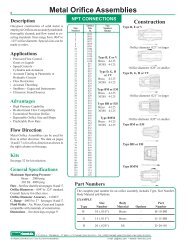
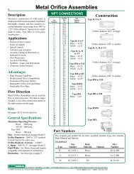
Description<br />
One-piece construction of solid metal is<br />
employed. <strong>Orifice</strong>s are accurately machined,<br />
thoroughly cleaned, and flow tested to exacting<br />
standards. Sizes range from .004" to<br />
.125" orifice diameter. Special sizes can be<br />
made to order. Type DEL is a two-piece<br />
construction.<br />
Applications<br />
• Precision Flow Control –<br />
Gases or Liquids<br />
• Speed <strong>Controls</strong> –<br />
Cylinders and Actuators<br />
• Accurate Timing in Pneumatic or<br />
Hydraulic Circuits<br />
• Flow Restriction<br />
• Accurate Throttling<br />
• Snubbers - Gages and Instruments<br />
• Ultrasonic Sound Sources<br />
Advantages<br />
• High Pressure Capability<br />
• Bi-directional Flow Compatibility<br />
• Economical Precision <strong>Orifice</strong><br />
• Repeatable <strong>Orifice</strong> Size and Shape<br />
• Predictable Flow Rate<br />
Flow Direction<br />
<strong>Metal</strong> <strong>Orifice</strong> <strong>Assemblies</strong> can be used for<br />
flow in either direction. The data on pages<br />
20 and 21 is for a flow direction as shown in<br />
the right column on this page.<br />
Kits<br />
See pages 30-31 for kit selection.<br />
General Specifications<br />
Maximum Operating Pressure –<br />
Brass 2000 psig<br />
303 SS 4000 psig<br />
Type DEL<br />
Brass 200 psig<br />
Flow – See flow chart for air on pages 20 and 21.<br />
<strong>Orifice</strong> Diameters – .004" to .125" standard.<br />
Consult factory for other sizes.<br />
<strong>Orifice</strong> Diameter Accuracy – ±.0003"<br />
C v Range – .00035 to .37 See pages 20 and 21.<br />
Fluid Media – Air, Water, Gases and Liquids<br />
compatible with materials of construction.<br />
Dimensions – See drawings on page 9.<br />
<strong>Metal</strong> <strong>Orifice</strong> <strong>Assemblies</strong><br />
NPT CONNECTIONS<br />
<strong>Orifice</strong> Size<br />
Size Dia. Number<br />
Number In. Range<br />
4 .0039<br />
5 .0051<br />
6 .0059<br />
7 .0071<br />
8 .0079<br />
9 .0091<br />
10 .0102<br />
11 .0110<br />
12 .0122<br />
13 .0130<br />
14 .0142<br />
15 .0150<br />
16 .016<br />
17 .017<br />
18 .018<br />
19 .019<br />
20 .020<br />
21 .021<br />
22 .022<br />
23 .023<br />
24 .024<br />
25 .025<br />
26 .026<br />
27 .027<br />
28 .028<br />
29 .029<br />
31 .031<br />
32 .032<br />
33 .033<br />
35 .035<br />
37 .037<br />
38 .038<br />
39 .039<br />
40 .040<br />
41 .041<br />
42 .042<br />
43 .043<br />
47 .047<br />
52 .052<br />
55 .055<br />
60 .060<br />
63 .063<br />
67 .067<br />
70 .070<br />
73 .073<br />
76 .076<br />
79 .079<br />
81 .081<br />
86 .086<br />
89 .089<br />
94 .094<br />
96 .096<br />
100 .100<br />
104 .104<br />
109 .109<br />
113 .113<br />
120 .120<br />
125 .125<br />
Part Numbers<br />
Type B, E or V<br />
Brass 4-125<br />
303SS 4-125<br />
Type D, G, H<br />
or VV<br />
Brass 4-125<br />
303SS 4-125<br />
Type BM or EM<br />
Brass 4-125<br />
303SS 4-125<br />
Type BH or EH<br />
Brass 4-125<br />
303SS 4-125<br />
Type BMM<br />
Brass 4-125<br />
303SS 4-125<br />
Type DEL<br />
Brass 4-63<br />
Type B, E or V<br />
<strong>Orifice</strong> diameter .021" or larger<br />
<strong>Orifice</strong> diameter .020" or smaller<br />
Type D, G, H or VV<br />
<strong>Orifice</strong> diameter .021" or larger<br />
<strong>Orifice</strong> diameter .020" or smaller<br />
Type BM or EM<br />
Type BH or EH<br />
Type BMM<br />
Type DEL<br />
Construction<br />
The complete part number for an orifice assembly includes Type, Size Number,<br />
Body Material and Options.<br />
EXAMPLES<br />
Size Body Part<br />
Type Number Material Options Number<br />
B 10 (.010") Brass – B-10-BR<br />
G 15 (.015") Brass – G-15-BR<br />
D 20 (.020") SS – D-20-SS<br />
P.O. BOX Q • TRUMBULL, CT 06611 • CT PHONE (203) 261-6711 • TOLL FREE PHONE (800) 533-3285 • FAX (203) 261-8331<br />
© O'KEEFE CONTROLS CO. • 2003 ALL RIGHTS RESERVED e-mail ca@okcc.com • website www.okcc.com
Type B, E or V<br />
Type D, G, H or VV<br />
Dimensions<br />
NPT - Both Ends<br />
NPT<br />
HEX<br />
L<br />
L<br />
HEX<br />
<strong>Metal</strong> <strong>Orifice</strong> <strong>Assemblies</strong><br />
NPT<br />
NPT CONNECTIONS<br />
Type Dim. L HEX NPT<br />
B .97" 7/16" 1/8"<br />
E 1.38" 9/16" 1/4"<br />
V 1.47" 11/16" 3/8"<br />
Type Dim. L HEX NPT<br />
D .88" 9/16" 1/8"<br />
G 1.25" 3/4" 1/4"<br />
VV 1.52" 7/8" 3/8"<br />
H 1.69" 1-1/16" 1/2"<br />
Specifications<br />
HEX NIPPLE<br />
Body and <strong>Orifice</strong> – Brass or 303 SS<br />
Threads – 1/8", 1/4" or 3/8" NPT<br />
Standard <strong>Orifice</strong> Sizes –<br />
Brass – .004" to .125" Dia.<br />
303 SS – .004" to .125" Dia.<br />
ADAPTER<br />
Body and <strong>Orifice</strong> – Brass or 303 SS<br />
Threads – 1/8", 1/4", 3/8" or 1/2" NPT<br />
Standard <strong>Orifice</strong> Sizes –<br />
Brass – .004" to .125" Dia.<br />
303 SS – .004" to .125" Dia.<br />
9<br />
Type BM or EM<br />
NPT<br />
L<br />
HEX<br />
Type Dim. L HEX NPT<br />
BM .580" 7/16" 1/8"<br />
EM .800" 9/16" 1/4"<br />
BLEED PLUG<br />
Body and <strong>Orifice</strong> – Brass or 303 SS<br />
Thread – 1/8" or 1/4" NPT<br />
Standard <strong>Orifice</strong> Sizes –<br />
Brass – .004" to .125" Dia.<br />
303 SS – .004" to .125" Dia.<br />
Type BH or EH<br />
L<br />
NPT<br />
Internal<br />
HEX<br />
Type Dim. L HEX NPT<br />
BH .30" 3/16" 1/8"<br />
EH .46" 1/4" 1/4"<br />
BLEED PLUG<br />
Body and <strong>Orifice</strong> – Brass or 303 SS<br />
Thread – 1/8" or 1/4" NPT<br />
Standard <strong>Orifice</strong> Sizes –<br />
Brass – .004" to .125" Dia.<br />
303 SS – .004" to .125" Dia.<br />
Type BMM<br />
.675"<br />
1/8" NPT<br />
7/16" HEX<br />
BLEED PLUG<br />
Body and <strong>Orifice</strong> – Brass or 303 SS<br />
Thread – 1/8" NPT<br />
Standard <strong>Orifice</strong> Sizes –<br />
Brass – .004" to .125" Dia.<br />
303 SS – .004" to .125" Dia.<br />
Type DEL<br />
.875"<br />
1/8" NPT<br />
.625"<br />
ELBOW<br />
Body and <strong>Orifice</strong> – Brass<br />
Threads – 1/8" NPT<br />
Standard <strong>Orifice</strong> Sizes – .004" to .063" Dia.<br />
<strong>Orifice</strong> – Press fit insert<br />
1/8" NPT<br />
P.O. BOX Q • TRUMBULL, CT 06611 • CT PHONE (203) 261-6711 • TOLL FREE PHONE (800) 533-3285 • FAX (203) 261-8331<br />
© O'KEEFE CONTROLS CO. • 2003 ALL RIGHTS RESERVED e-mail ca@okcc.com • website www.okcc.com
10<br />
Description<br />
The inserts shown on this page are designed<br />
to press-fit into openings accurately machined<br />
in fittings, manifolds and custom parts. There<br />
is a choice of insert sizes and materials of<br />
construction.<br />
Applications<br />
The inserts can be used with a wide variety of<br />
fittings by accurately machining the inside of<br />
the fitting. The orifice is then pressed into the<br />
fitting for control of the flow rate of liquids or<br />
gases.<br />
Manifolds or other custom assemblies that<br />
require flow rate control of fluids can be<br />
accurately machined to press fit the orifices<br />
shown on this page and on page 11.<br />
General Specifications<br />
Maximum Operating Pressure<br />
Insert Only (see exceptions)<br />
Brass – 2000 psig<br />
303SS – 4000 psig<br />
316SS – 4000 psig<br />
exceptions IAS, US<br />
Maximum Differential Pressure –<br />
100 psid<br />
Flow – See flow chart for air flow on pages<br />
20, 21 and 22.<br />
<strong>Orifice</strong> Diameters – .004" to .125". See<br />
chart at right. Consult factory for other sizes.<br />
<strong>Orifice</strong> Diameter Accuracy – ±.0003"<br />
C v Range – .000030 to .37<br />
See pages 20, 21 and 22.<br />
Fluid Media – Air, Water, Gases and Liquids<br />
compatible with materials of construction.<br />
Dimensions – See drawings in right hand<br />
column of this page and on page 11.<br />
Press Fit – See drawings in right hand<br />
column of this page and on page 11.<br />
Materials<br />
Type IA, AM, IF – Brass or 303 SS<br />
Type IAS – Brass, 304 SS Screen<br />
Type I B, I E, I J – 303 SS<br />
I K, U<br />
Type IH – Brass or 303 SS<br />
with sapphire orifice<br />
Type IL – Brass<br />
Type IC, I D – 316 SS<br />
Type US – 303 SS, 304 SS Screen<br />
<strong>Metal</strong> <strong>Orifice</strong> <strong>Assemblies</strong><br />
<strong>Orifice</strong> Size<br />
Size Dia. Number<br />
Number In. Range<br />
4 .0039<br />
5 .0051<br />
6 .0059<br />
7 .0071<br />
8 .0079<br />
9 .0091<br />
10 .0102<br />
11 .0110<br />
12 .0122<br />
13 .0130<br />
14 .0142<br />
15 .0150<br />
16 .016<br />
17 .017<br />
18 .018<br />
19 .019<br />
20 .020<br />
21 .021<br />
22 .022<br />
23 .023<br />
24 .024<br />
25 .025<br />
26 .026<br />
27 .027<br />
28 .028<br />
29 .029<br />
31 .031<br />
32 .032<br />
33 .033<br />
35 .035<br />
37 .037<br />
38 .038<br />
39 .039<br />
40 .040<br />
41 .041<br />
42 .042<br />
43 .043<br />
47 .047<br />
52 .052<br />
55 .055<br />
60 .060<br />
63 .063<br />
67 .067<br />
70 .070<br />
73 .073<br />
76 .076<br />
79 .079<br />
81 .081<br />
86 .086<br />
89 .089<br />
94 .094<br />
96 .096<br />
100 .100<br />
104 .104<br />
109 .109<br />
113 .113<br />
120 .120<br />
125 .125<br />
INSERTS<br />
Type AM<br />
4-35<br />
Type IA<br />
4-63<br />
Type IAS<br />
4-35<br />
Type IB<br />
4-25<br />
Type IC<br />
4-63<br />
Type ID<br />
4-125<br />
Type IE<br />
4-35<br />
Type IF<br />
4-63<br />
Type IH<br />
(metric)<br />
3-64<br />
see page 3<br />
Type I J<br />
4-125<br />
Type IK<br />
4-20<br />
Type IL<br />
4-35<br />
Type U<br />
4-63<br />
Type US<br />
4-35<br />
Type AM<br />
Type IA<br />
Type IAS<br />
Type IB<br />
.087"/.089" Dia.<br />
.258"/.259" Dia.<br />
.258"/.259" Dia.<br />
.276"<br />
.196"<br />
.156"<br />
Press Fit Into .256"/.257" Dia.<br />
Press Fit Into .256"/.257" Dia.<br />
.250"<br />
.125"<br />
Press Fit Into Bore<br />
.0930"/.0940" Dia.<br />
CONSTRUCTION<br />
.156"<br />
DIMENSIONS<br />
CONSTRUCTION<br />
Integral<br />
Screen<br />
DIMENSIONS<br />
.145" Dia. .128"/.129" Dia.<br />
Press Fit Into<br />
.126"/.127" Dia.<br />
CONSTRUCTION<br />
DIMENSIONS<br />
DIMENSIONS<br />
.0945"/.0950" Dia.<br />
CONSTRUCTION<br />
Custom Inserts<br />
Where quantity requirements exceed 1000<br />
pieces, custom inserts can be manufactured<br />
in brass, stainless steel, or special materials<br />
to the dimensions required. Provide a<br />
dimension drawing, material specifications,<br />
and quantities to our technical service<br />
department to obtain price and delivery<br />
quotations.<br />
P.O. BOX Q • TRUMBULL, CT 06611 • CT PHONE (203) 261-6711 • TOLL FREE PHONE (800) 533-3285 • FAX (203) 261-8331<br />
© O'KEEFE CONTROLS CO. • 2003 ALL RIGHTS RESERVED e-mail ca@okcc.com • website www.okcc.com
<strong>Metal</strong> <strong>Orifice</strong> <strong>Assemblies</strong><br />
INSERTS<br />
11<br />
Type IC<br />
Press Fit Into Bore<br />
.1905"/.1910" Dia.<br />
DIMENSIONS<br />
Type IH<br />
Press Fit Into<br />
.0980" / .0990"<br />
.080"<br />
DIMENSIONS<br />
.1930"/.1935"<br />
Dia.<br />
.125"<br />
.190"<br />
.184"/.186" Dia.<br />
CONSTRUCTION<br />
Size Numbers 3-64<br />
(metric)<br />
See page 3<br />
.0995"<br />
.1000" Dia.<br />
CONSTRUCTION<br />
Type ID<br />
Press Fit Into<br />
.4125" / .4135"<br />
.440"<br />
DIMENSIONS<br />
.4140"<br />
.4145" Dia.<br />
Type IJ<br />
Press Fit Into<br />
.3785" / .3795"<br />
.270"<br />
DIMENSIONS<br />
.3800"<br />
.3805" Dia.<br />
Type U<br />
Press Fit Into<br />
.2795" / .2805"<br />
.280"<br />
DIMENSIONS<br />
.2810"<br />
.2815" Dia.<br />
CONSTRUCTION<br />
10-32 Thread<br />
CONSTRUCTION<br />
19°<br />
CONSTRUCTION<br />
Type IE<br />
Press Fit Into<br />
.1230" / .1235"<br />
.060"<br />
DIMENSIONS<br />
Type IK<br />
Press Fit Into<br />
.0605" / .0610"<br />
.1240"<br />
.1250" Dia.<br />
.062"<br />
DIMENSIONS Type US<br />
Press Fit Into<br />
.2795" / .2805"<br />
.0615"<br />
.0625" Dia.<br />
.230"<br />
DIMENSIONS<br />
.2815" Dia.<br />
.2825"<br />
CONSTRUCTION<br />
.031<br />
Spherical R.<br />
CONSTRUCTION<br />
Screen<br />
Both Ends<br />
CONSTRUCTION<br />
Type IF<br />
Press Fit Into<br />
.2475" / .2485"<br />
.270"<br />
10-32 Thread<br />
DIMENSIONS<br />
.2490"<br />
.2495" Dia. CONSTRUCTION<br />
CONSTRUCTION<br />
Type IL<br />
Press Fit Into<br />
.098" / .099"<br />
.080"<br />
DIMENSIONS<br />
.0995"<br />
Dia.<br />
.1000"<br />
<strong>Orifice</strong> Diameters<br />
See chart on page 10 for sizes available<br />
for each insert type. Consult factory for<br />
other sizes.<br />
Part Numbers<br />
The complete part number for an orifice assembly includes Type, Size Number,<br />
Body Material and Options.<br />
EXAMPLES<br />
Size Body Part<br />
Type Number Material Options Number<br />
IB 6 (.006") SS – IB-6-SS<br />
Flow Direction<br />
<strong>Metal</strong> <strong>Orifice</strong> <strong>Assemblies</strong> can be used for<br />
flow in either direction. The data on<br />
pages 20, 21 and 22 is for a flow direction<br />
as shown in the right column on page 10<br />
and throughout this page.<br />
AM 10 (.010") SS – AM-10-SS<br />
IA 20 (.020") Brass – IA-20-BR<br />
P.O. BOX Q • TRUMBULL, CT 06611 • CT PHONE (203) 261-6711 • TOLL FREE PHONE (800) 533-3285 • FAX (203) 261-8331<br />
© O'KEEFE CONTROLS CO. • 2003 ALL RIGHTS RESERVED e-mail ca@okcc.com • website www.okcc.com
12<br />
<strong>Metal</strong> <strong>Orifice</strong> <strong>Assemblies</strong><br />
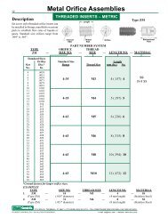
Description<br />
Set screw style threaded orifice inserts can<br />
be installed in fittings, manifolds or custom<br />
parts to establish flow rates of liquids or<br />
gases. Standard size orifices range from<br />
.004" to .063".<br />
PART NUMBER SYSTEM<br />
TYPE ORIFICE THREAD<br />
ZM — SIZE NO. — SIZE — LENGTH NO. — MATERIAL<br />
Standard Sizes<br />
<strong>Orifice</strong> Standard Size Length<br />
Size Dia.* Range Thread Size mm (In.) No.<br />
No. In.<br />
4 .0039<br />
5 .0051<br />
6 .0059<br />
7 .0071<br />
8 .0079<br />
9 .0091<br />
10 .0102<br />
11 .0110<br />
12 .0122<br />
13 .0130<br />
14 .0142<br />
15 .0150<br />
16 .016<br />
17 .017<br />
18 .018<br />
19 .019<br />
20 .020<br />
21 .021<br />
22 .022<br />
23 .023<br />
24 .024<br />
25 .025<br />
26 .026<br />
27 .027<br />
28 .028<br />
29 .029<br />
31 .031<br />
32 .032<br />
33 .033<br />
35 .035<br />
37 .037<br />
38 .038<br />
39 .039<br />
40 .040<br />
41 .041<br />
42 .042<br />
43 .043<br />
47 .047<br />
52 .052<br />
55 .055<br />
60 .060<br />
63 .063<br />
THREADED INSERTS – METRIC<br />
Internal<br />
HEX<br />
Length<br />
Thread<br />
Size<br />
4-35 M3 4 (.157) 4<br />
4-35 M4 5 (.197) 5<br />
4-63 M5 6 (.236) 6<br />
4-63 M6 8 (.315) 8<br />
4-63 M8 10 (.394) 10<br />
4-63 M10 12 (.472) 12<br />
Type ZM<br />
Bidirectional<br />
Flow<br />
*Consult factory for larger orifice sizes.<br />
EXAMPLES<br />
TYPE SIZE NO. THREAD SIZE LENGTH NO. MATERIAL<br />
1. ZM — 10 — M3 — 4 — SS<br />
(Type ZM) (.010" diameter) (4 mm length) (Stainless Steel)<br />
2. ZM — 31 — M6 — 8 — SS<br />
(Type ZM) (.031" diameter) (8 mm length) (Stainless Steel)<br />
<strong>Orifice</strong><br />
SS<br />
18-8 SS<br />
P.O. BOX Q • TRUMBULL, CT 06611 • CT PHONE (203) 261-6711 • TOLL FREE PHONE (800) 533-3285 • FAX (203) 261-8331<br />
© O'KEEFE CONTROLS CO. • 2003 ALL RIGHTS RESERVED e-mail ca@okcc.com • website www.okcc.com
Description<br />
Set screw style threaded orifice inserts can<br />
be installed in fittings, manifolds or custom<br />
parts to establish flow rates of liquids or<br />
gases. Standard size orifices range from<br />
.004" to .063". Both brass and 316 SS<br />
materials are offered.<br />
<strong>Metal</strong> <strong>Orifice</strong> <strong>Assemblies</strong><br />
THREADED INSERTS – INCH<br />
Internal<br />
HEX<br />
Length<br />
Thread<br />
Size<br />
<strong>Orifice</strong><br />
Type Z<br />
Bidirectional<br />
Flow<br />
PART NUMBER SYSTEM<br />
TYPE ORIFICE THREAD<br />
Z — SIZE NO. — SIZE — LENGTH NO. — MATERIAL<br />
13<br />
Standard Sizes<br />
<strong>Orifice</strong> Standard Size Length<br />
Size Dia.* Range Thread Size In. No.<br />
No. In.<br />
4 .0039 Thread Size No.<br />
5 .0051<br />
6 .0059<br />
7 .0071<br />
8 .0079<br />
9 .0091<br />
10 .0102<br />
11 .0110<br />
12 .0122<br />
13 .0130<br />
14 .0142<br />
15 .0150<br />
16 .016<br />
17 .017<br />
18 .018<br />
19 .019<br />
20 .020<br />
21 .021<br />
22 .022<br />
23 .023<br />
24 .024<br />
25 .025<br />
26 .026<br />
27 .027<br />
28 .028<br />
29 .029<br />
31 .031<br />
32 .032<br />
33 .033<br />
35 .035<br />
37 .037<br />
38 .038<br />
39 .039<br />
40 .040<br />
41 .041<br />
42 .042<br />
43 .043<br />
47 .047<br />
52 .052<br />
55 .055<br />
60 .060<br />
63 .063<br />
6 • 32 1/8 2 BR - Brass<br />
Brass 4-35 6 • 32 3/16 3<br />
SS 4-35 1/4 4 SS - 316SS<br />
8 • 32 1/8 2<br />
Brass 4-35 8 • 32 3/16 3<br />
SS 4-35 1/4 4<br />
10 • 32 3/16 3<br />
Brass 4-63 10 • 32 1/4 4<br />
SS 4-63 3/8 6<br />
1/4 • 20 1/4 4<br />
Brass 4-63 1/4 • 20 3/8 6<br />
SS 4-63 1/2 8<br />
5/16 • 18 1/4 4<br />
Brass 4-63 5/16 • 18 3/8 6<br />
SS 4-63 1/2 8<br />
3/8 • 16 3/8 6<br />
Brass 4-63 3/8 • 16 1/2 8<br />
SS 4-63<br />
*Consult factory for larger orifice sizes.<br />
EXAMPLES<br />
TYPE SIZE NO. THREAD SIZE LENGTH NO. MATERIAL<br />
1. Z — 10 — 10 • 32 — 6 — BR<br />
(Type Z) (.010" diameter) (10 • 32 thread) (3/8" length) (Brass)<br />
2. Z — 31 — 1/4 • 20 — 4 — SS<br />
(Type Z) (.031" diameter) (1/4 • 20 thread) (1/4" length) (Stainless Steel)<br />
P.O. BOX Q • TRUMBULL, CT 06611 • CT PHONE (203) 261-6711 • TOLL FREE PHONE (800) 533-3285 • FAX (203) 261-8331<br />
© O'KEEFE CONTROLS CO. • 2003 ALL RIGHTS RESERVED e-mail ca@okcc.com • website www.okcc.com
14<br />
Description<br />
Precision orifice assemblies that adapt to common<br />
fittings used in the process industry are<br />
described on pages 14 and 15. Press-fit inserts<br />
are used with standard compression tube fittings<br />
to form a precision orifice assembly. The<br />
fittings shown here are for 1/4" OD tubing, or<br />
3/16" OD tubing.<br />
Applications<br />
Compression fittings are used with a metal or<br />
rigid plastic tubing. These fittings are used in<br />
instrumentation for process control systems.<br />
The nature of the connectors allow for easy<br />
disassembly and re-assembly without the need<br />
for teflon tape or sealants.<br />
Advantages<br />
• High Pressure Capability<br />
• Bi-directional Flow<br />
• Economical Precision <strong>Orifice</strong><br />
• Repeatable <strong>Orifice</strong> Size and Shape<br />
• Predictable Flow Rate<br />
General Specifications<br />
Flow Direction – Suitable for flow in either<br />
direction. Data on pages 20 and 21 is measured<br />
for flow direction shown in right column of<br />
this page.<br />
Flow – See flow chart for air flow on pages 20<br />
and 21.<br />
C v Range – .00035 to .088<br />
See pages 20 and 21.<br />
<strong>Orifice</strong> Size Numbers – 4 to 63<br />
<strong>Orifice</strong> Sizes – .0039" to .063"<br />
<strong>Orifice</strong> Diameter Accuracy – ±.0003"<br />
Fluid Media – Air, Water, Gases and Liquids<br />
compatible with materials of construction.<br />
Dimensions – See drawings on page 15.<br />
Materials of Construction – See page 15.<br />
Maximum Operating Pressure– See page 15.<br />
Part Numbers<br />
<strong>Metal</strong> <strong>Orifice</strong> <strong>Assemblies</strong><br />
COMPRESSION FITTINGS<br />
<strong>Orifice</strong> Size<br />
Size Dia Number<br />
Number In. Range<br />
4 .0039<br />
5 .0051<br />
6 .0059<br />
7 .0071<br />
8 .0079<br />
9 .0091<br />
10 .0102<br />
11 .0110<br />
12 .0122<br />
13 .0130<br />
14 .0142<br />
15 .0150<br />
16 .016<br />
17 .017<br />
18 .018<br />
19 .019<br />
20 .020<br />
21 .021<br />
22 .022<br />
23 .023<br />
24 .024<br />
25 .025<br />
26 .026<br />
27 .027<br />
28 .028<br />
29 .029<br />
31 .031<br />
32 .032<br />
33 .033<br />
35 .035<br />
37 .037<br />
38 .038<br />
39 .039<br />
40 .040<br />
41 .041<br />
42 .042<br />
43 .043<br />
47 .047<br />
52 .052<br />
55 .055<br />
60 .060<br />
63 .063<br />
The complete part number for an orifice assembly includes Type, Size Number,<br />
Body Material and Options.<br />
EXAMPLES<br />
Size Body Part<br />
Type Number Material Options Number<br />
IC-MC4 6 (.006") SS – IC-MC4-6-SS<br />
IC-400R4 13 (.013") SS – IC-400R4-13-SS<br />
AM-3006 35 (.035") Brass – AM-3006-35-BR<br />
IC-UT4 28 (.028") SS – IC-UT4-28-SS<br />
Type IC-MC4<br />
4-63<br />
Type IC-MC6<br />
4-63<br />
Type IC-4006<br />
4-63<br />
Type AM-3006<br />
4-35<br />
Type IC-UT4<br />
4-63<br />
Type IC-400R4<br />
4-63<br />
Type IC-PC4<br />
4-63<br />
Type IC-DM4<br />
4-63<br />
Construction<br />
Type IC-MC4, IC-MC6<br />
Type IC-4006<br />
Type AM-3006<br />
Type IC-UT4<br />
Type IC-400R4<br />
Type IC-PC4<br />
Type IC-DM4<br />
P.O. BOX Q • TRUMBULL, CT 06611 • CT PHONE (203) 261-6711 • TOLL FREE PHONE (800) 533-3285 • FAX (203) 261-8331<br />
© O'KEEFE CONTROLS CO. • 2003 ALL RIGHTS RESERVED e-mail ca@okcc.com • website www.okcc.com
Type IC-MC4<br />
Type IC-MC6<br />
Type IC-4006<br />
Type AM-3006<br />
Dimensions<br />
L<br />
1/4"<br />
Tube OD<br />
NPT<br />
A HEX 9/16" HEX<br />
9/16"<br />
HEX<br />
(2 places)<br />
1/2" HEX<br />
(2 places)<br />
1.61"<br />
1/2" HEX<br />
1.47"<br />
7/16" HEX<br />
<strong>Metal</strong> <strong>Orifice</strong> <strong>Assemblies</strong><br />
15<br />
1/4"<br />
Tube OD<br />
(2 places)<br />
3/16"<br />
Tube OD<br />
(2 places)<br />
COMPRESSION FITTINGS<br />
TYPE NPT L (in) A HEX<br />
IC-MC4 1/4" 1.48 9/16"<br />
IC-MC6 3/8" 1.51 11/16"<br />
Specifications<br />
TUBE ADAPTER<br />
Body – 316 SS<br />
<strong>Orifice</strong> – 316 SS<br />
Maximum Body Pressure – 4000 psig<br />
Maximum Pressure Differential – 200 psid*<br />
<strong>Orifice</strong> Sizes – .004" to .063" dia.<br />
TUBE UNION – 1/4" OD<br />
Body – 316 SS<br />
<strong>Orifice</strong> – 316 SS<br />
Maximum Body Pressure – 4000 psig<br />
Maximum Pressure Differential – 200 psid*<br />
<strong>Orifice</strong> Sizes – .004" to .063" dia.<br />
TUBE UNION – 3/16" OD<br />
Body – Brass or 316 SS<br />
<strong>Orifice</strong> – Brass or 303 SS<br />
Maximum Body Pressure – 4000 psig<br />
Maximum Pressure Differential – 200 psid*<br />
<strong>Orifice</strong> Sizes – .004" to .035" dia.<br />
Type IC-UT4<br />
1.06"<br />
2.12"<br />
9/16" HEX<br />
(3 places)<br />
1/4"<br />
Tube OD<br />
(3 places)<br />
UNION TEE<br />
Body – 316 SS<br />
<strong>Orifice</strong> – 316 SS<br />
Maximum Body Pressure – 4000 psig<br />
Maximum Pressure Differential – 200 psid*<br />
<strong>Orifice</strong> Sizes – .004" to .063" dia.<br />
Type IC-400R4<br />
1/4"<br />
Tube OD<br />
1.54"<br />
1/2" HEX<br />
9/16" HEX<br />
1/4"<br />
Tube OD<br />
TUBE ADAPTER<br />
Body – 316 SS<br />
<strong>Orifice</strong> – 316 SS<br />
Maximum Body Pressure – 4000 psig<br />
Maximum Pressure Differential – 200 psid*<br />
<strong>Orifice</strong> Sizes – .004" to .063" dia.<br />
Type IC-PC4<br />
.37"<br />
.97"<br />
.74"<br />
1/4"<br />
Tube OD<br />
PORT CONNECTOR<br />
Body – 316 SS<br />
<strong>Orifice</strong> – 316 SS<br />
Maximum Body Pressure – 4000 psig<br />
Maximum Pressure Differential – 1000 psid*<br />
in direction shown<br />
<strong>Orifice</strong> Sizes – .004" to .063" dia.<br />
Type IC-DM4<br />
1.55"<br />
5/8" HEX<br />
*psid – pounds per square inch differential<br />
DOUBLE MALE UNION<br />
Body – 316 SS<br />
<strong>Orifice</strong> – 316 SS<br />
Maximum Body Pressure – 4000 psig<br />
Maximum Pressure Differential –1000 psid*<br />
in direction shown<br />
<strong>Orifice</strong> Sizes – .004" to .063" dia.<br />
Made from Swagelok 1/4" VCR fittings<br />
P.O. BOX Q • TRUMBULL, CT 06611 • CT PHONE (203) 261-6711 • TOLL FREE PHONE (800) 533-3285 • FAX (203) 261-8331<br />
© O'KEEFE CONTROLS CO. • 2003 ALL RIGHTS RESERVED e-mail ca@okcc.com • website www.okcc.com
16<br />
Type IA-H0134<br />
IA-H0334<br />
IA-H0534<br />
IA-H0734<br />
• For Plastic Tubing<br />
1/8", 5/32", 3/16" or 1/4" OD<br />
• Easy Connect/Disconnect<br />
• Type IA Insert<br />
• <strong>Orifice</strong> Size Numbers 4 - 63<br />
Type IA-H0135<br />
IA-H0335<br />
IA-H0535<br />
IA-H0735<br />
• For Plastic Tubing<br />
1/8", 5/32", 3/16" or 1/4" OD<br />
• Easy Connect/Disconnect<br />
• Type IA Insert<br />
• <strong>Orifice</strong> Size Numbers 4 - 63<br />
Type IL-H0132<br />
IL-H0332<br />
IL-H0532<br />
IL-H0732<br />
• For Plastic Tubing<br />
1/8", 5/32", 3/16" or 1/4" OD<br />
• Easy Tubing Connect/<br />
Disconnect<br />
• Type IL Insert<br />
• <strong>Orifice</strong> Size Numbers 4 - 35<br />
HOW PUSH-ON FITTINGS WORK!<br />
BRASS<br />
BODY<br />
TUBE<br />
SEAL &<br />
LOCK<br />
<strong>Metal</strong> <strong>Orifice</strong> <strong>Assemblies</strong><br />
PUSH-ON TUBE ADAPTERS<br />
PUSH-ON TUBE ADAPTER<br />
1/8" NPT x 1/8" OD Tube<br />
1/8" NPT x 5/32" OD Tube<br />
1/8" NPT x 3/16" OD Tube<br />
1/8" NPT x 1/4" OD Tube<br />
Body – Brass/Plastic<br />
<strong>Orifice</strong> –Brass<br />
Seals – Buna-N<br />
Max. Body Pressure – 140 psig<br />
<strong>Orifice</strong> Sizes – .004" to .063" dia.<br />
<strong>Orifice</strong> Size No. 4-63<br />
PUSH-ON TUBE ADAPTER<br />
1/4" NPT x 1/8" OD Tube<br />
1/4" NPT x 5/32" OD Tube<br />
1/4" NPT x 3/16" OD Tube<br />
1/4" NPT x 1/4" OD Tube<br />
Body – Brass/Plastic<br />
<strong>Orifice</strong> –Brass<br />
Seals – Buna-N<br />
Max. Body Pressure – 140 psig<br />
<strong>Orifice</strong> Sizes – .004" to .063" dia.<br />
<strong>Orifice</strong> Size No. 4-63<br />
PLASTIC<br />
TUBING<br />
PUSH-ON TUBE ADAPTER<br />
10-32 x 1/8" OD Tube<br />
10-32 x 5/32" OD Tube<br />
10-32 x 3/16" OD Tube<br />
10-32 x 1/4" OD Tube<br />
Body – Brass/Plastic<br />
<strong>Orifice</strong> –Brass<br />
Seals – Buna-N<br />
Max. Body Pressure – 140 psig<br />
<strong>Orifice</strong> Sizes – .004" to .035" dia.<br />
<strong>Orifice</strong> Size No. 4-35<br />
RELEASE<br />
BUTTON<br />
Type L T HEX TUBE OD<br />
IA-H0134 .87" 1/8" NPT 7/16" 1/8"<br />
IA-H0334 .87" 1/8" NPT 7/16" 5/32"<br />
IA-H0534 .87" 1/8" NPT 1/2" 3/16"<br />
IA-H0734 .89" 1/8" NPT 5/8" 1/4"<br />
Type L T HEX TUBE OD<br />
IA-H0135 .77" 1/4" NPT 5/8" 1/8"<br />
IA-H0335 .77" 1/4" NPT 5/8" 5/32"<br />
IA-H0535 .83" 1/4" NPT 5/8" 3/16"<br />
IA-H0735 .91" 1/4" NPT 5/8" 1/4"<br />
Type L T HEX TUBE OD<br />
IL-H0132 .66" #10-32 9/32" 1/8"<br />
IL-H0332 .67" #10-32 5/16" 5/32"<br />
IL-H0532 .95" #10-32 5/16" 3/16"<br />
IL-H0732 .73" #10-32 7/16" 1/4"<br />
P.O. BOX Q • TRUMBULL, CT 06611 • CT PHONE (203) 261-6711 • TOLL FREE PHONE (800) 533-3285 • FAX (203) 261-8331<br />
© O'KEEFE CONTROLS CO. • 2003 ALL RIGHTS RESERVED e-mail ca@okcc.com • website www.okcc.com<br />
T<br />
T<br />
T<br />
L<br />
L<br />
HEX<br />
L<br />
HEX<br />
HEX<br />
TUBE<br />
OD<br />
TUBE<br />
OD<br />
TUBE<br />
OD<br />
Size Numbers<br />
<strong>Metal</strong><br />
<strong>Orifice</strong> Size<br />
Number<br />
<strong>Orifice</strong><br />
Dia.<br />
in.<br />
4 .0039<br />
5 .0051<br />
6 .0059<br />
7 .0071<br />
8 .0079<br />
9 .0091<br />
10 .0102<br />
11 .0110<br />
12 .0122<br />
13 .0130<br />
14 .0142<br />
15 .0150<br />
16 .016<br />
17 .017<br />
18 .018<br />
19 .019<br />
20 .020<br />
21 .021<br />
22 .022<br />
23 .023<br />
24 .024<br />
25 .025<br />
26 .026<br />
27 .027<br />
28 .028<br />
29 .029<br />
31 .031<br />
32 .032<br />
33 .033<br />
35 .035<br />
37 .037<br />
38 .038<br />
39 .039<br />
40 .040<br />
41 .041<br />
42 .042<br />
43 .043<br />
47 .047<br />
52 .052<br />
55 .055<br />
60 .060<br />
63 .063<br />
See pages 20 and 21 for<br />
orifice flow charts.<br />
Part Numbers<br />
The complete part number for these orifice assemblies includes Type, Size Number and Body Material.<br />
EXAMPLES<br />
Type<br />
Size<br />
Number<br />
Body<br />
Material<br />
Part<br />
Number<br />
IA-H0134 (1/8" NPT x 1/8" OD Tube) 10 (.010") B/P (all) IA-H0134-10-B/P<br />
IA-H0735 (1/4" NPT x 1/4" OD Tube) 25 (.025") B/P (all) IA-H0735-25-B/P<br />
IL-H0332 (10-32 x 5/32" OD Tube) 6 (.006") B/P (all) IL-H0332-6-B/P
<strong>Metal</strong> <strong>Orifice</strong> <strong>Assemblies</strong><br />
17<br />
REPLACEABLE ORIFICES<br />
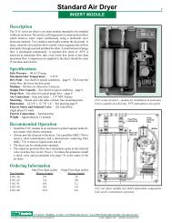
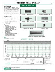
Description<br />
The replaceable orifice assembly provides the<br />
opportunity to easily remove and replace an<br />
orifice insert. Available in either brass or stainless<br />
steel with viton elastomers the assembly<br />
can be used for metering the flow of liquids or<br />
gases. Optional cleanable screens can be<br />
selected to protect small orifices from contamination.<br />
Micro-<strong>Orifice</strong>s ® down to .0003"<br />
diameter are also available.<br />
Type Y2<br />
• 1/8" NPT Connections<br />
• <strong>Orifice</strong> Element Replaceable<br />
• Type IA Insert<br />
(see page 10 for P/N – insert only)<br />
• <strong>Orifice</strong> Size Numbers 4 - 63<br />
• Flow Chart (see pages 20 and 21)<br />
Type Y2SS<br />
• 1/8" NPT Connections<br />
• <strong>Orifice</strong> Element Replaceable<br />
• Type IA Insert<br />
(see page 10 for P/N – insert only)<br />
• Dual Screens<br />
• <strong>Orifice</strong> Size Numbers 4 - 35<br />
• Flow Chart (see pages 20 and 21)<br />
Applications<br />
• Leak Test Reference Standards<br />
• Prototype Test and Development<br />
• Flow Inspection Equipment<br />
• Calibration of Flow Measuring Equipment<br />
• Flexible <strong>Orifice</strong> Size Requirements<br />
1/8" NPT – BOTH ENDS<br />
5/8" HEX – BOTH ENDS<br />
1/8" NPT – BOTH ENDS<br />
SCREEN<br />
2.25"<br />
5/8" HEX – BOTH ENDS<br />
2.25"<br />
REPLACEABLE ORIFICE<br />
REPLACEABLE ORIFICE<br />
SCREEN<br />
Types Y2, Y2SS and Y2LPSS are<br />
available in brass or stainless steel.<br />
Replaceable orifices and cleanable<br />
screens are features.<br />
REPLACEABLE ORIFICE<br />
ASSEMBLY<br />
Body – Brass or 303 SS<br />
<strong>Orifice</strong> – Brass or 303 SS<br />
Seals – Viton<br />
Maximum Operating Pressure –<br />
200 psig<br />
<strong>Orifice</strong> Sizes – .004" to .063" dia.<br />
See page 16 for orifice size numbers.<br />
TYPE Y2 WITH DUAL SCREENS<br />
Body – Brass or 303 SS<br />
<strong>Orifice</strong> – Brass or 303 SS<br />
Seals – Viton<br />
Screens – 304 SS<br />
Maximum Operating Pressure –<br />
200 psig<br />
<strong>Orifice</strong> Sizes – .004" to .035" dia.<br />
See page 16 for orifice size numbers.<br />
Type Y2LPSS<br />
• 1/8" NPT Connections<br />
• <strong>Orifice</strong> Element Replaceable<br />
• Type IALP Insert<br />
• Flow Chart (see page 25)<br />
• Dual Screens<br />
• <strong>Orifice</strong> Size Numbers 0C to 5<br />
(see chart below)<br />
• For Larger <strong>Orifice</strong>s Use Type Y2SS<br />
Micro-<strong>Orifice</strong>s ®<br />
Size <strong>Orifice</strong><br />
Number Dia. in.<br />
0C .0003<br />
0E .0005<br />
0G .0007<br />
1 .0010<br />
1E .0015<br />
2 .0020<br />
2E .0025<br />
3 .0030<br />
3E .0035<br />
4 .0040<br />
5 .0050<br />
1/8" NPT – BOTH ENDS<br />
SCREEN<br />
5/8" HEX – BOTH ENDS<br />
2.25"<br />
Part Numbers<br />
REPLACEABLE ORIFICE<br />
SCREEN<br />
REPLACEABLE Micro-<strong>Orifice</strong>s ®<br />
Body – Brass or 303 SS<br />
<strong>Orifice</strong> – Brass or 303 SS<br />
Seals – Viton<br />
Screens – 304 SS<br />
Maximum Operating Pressure –<br />
200 psig<br />
<strong>Orifice</strong> Sizes – .0003" to .005" dia.<br />
See below for Micro-<strong>Orifice</strong> ® size numbers.<br />
The complete part number for a replaceable orifice assembly includes Type, Size Number and<br />
Body Materials.<br />
EXAMPLES<br />
Size Body Part<br />
Type Number Material Number<br />
Y2 25 (.025") Brass Y2-25-BR<br />
Y2SS (includes 2 screens) 6 (.006") Brass Y2SS-6-BR<br />
Y2LPSS<br />
(includes 2 screens and Micro-<strong>Orifice</strong>s ® ) 0G (.0007") SS Y2LPSS-0G-SS<br />
®Registered trademark of <strong>O'Keefe</strong> <strong>Controls</strong> Co.<br />
P.O. BOX Q • TRUMBULL, CT 06611 • CT PHONE (203) 261-6711 • TOLL FREE PHONE (800) 533-3285 • FAX (203) 261-8331<br />
© O'KEEFE CONTROLS CO. • 2003 ALL RIGHTS RESERVED e-mail ca@okcc.com • website www.okcc.com
18<br />
Description<br />
Precision orifice assemblies that adapt to<br />
common fittings used in process instruments<br />
and hydraulic systems are shown on pages<br />
18 and 19. Types K4, R4 and RG4 are used<br />
with nominal 1/4" tube fittings. Type BFS is<br />
for 45° flare fittings and Type CFJ is for 37°<br />
flare fittings. Type OD is a pipe adapter.<br />
Applications<br />
• Type K4 is a 1/4" OD Tube and is suitable<br />
for use with a wide variety of compression<br />
fittings.<br />
• Type K2 is for 1/8" OD Tube fittings.<br />
• Types R4 and RG4 are suitable for use<br />
with face seal fittings.<br />
• Types BFS and CFJ are used in hydraulic<br />
circuits, having SAE flare connections.<br />
Advantages<br />
• High Pressure Capability<br />
• Bi-directional Flow<br />
• Economical Precision <strong>Orifice</strong><br />
• Repeatable <strong>Orifice</strong> Size and Shape<br />
• Predictable Flow Rate<br />
General Specifications<br />
Flow Direction – Suitable for flow in either<br />
direction. Data on pages 20 and 21 is measured<br />
for flow direction shown in right column<br />
of this page.<br />
Flow – See flow chart for air flow on pages<br />
20 and 21.<br />
C V<br />
Range – .00035 to .37<br />
See pages 20 and 21.<br />
<strong>Orifice</strong> Diameter Accuracy – ±.0003"<br />
Fluid Media – Air, Water, Gases and Liquids<br />
compatible with materials of construction.<br />
Dimensions – See drawings on page 19.<br />
Materials of Construction –<br />
See page 19.<br />
Maximum Operating Pressure –<br />
See page 19.<br />
Part Numbers<br />
<strong>Metal</strong> <strong>Orifice</strong> <strong>Assemblies</strong><br />
MISCELLANEOUS<br />
<strong>Orifice</strong> Size<br />
Size Dia. Number<br />
Number In. Range<br />
4 .0039<br />
5 .0051<br />
6 .0059<br />
7 .0071<br />
8 .0079<br />
9 .0091<br />
10 .0102<br />
11 .0110<br />
12 .0122<br />
13 .0130<br />
14 .0142<br />
15 .0150<br />
16 .016<br />
17 .017<br />
18 .018<br />
19 .019<br />
20 .020<br />
21 .021<br />
22 .022<br />
23 .023<br />
24 .024<br />
25 .025<br />
26 .026<br />
27 .027<br />
28 .028<br />
29 .029<br />
31 .031<br />
32 .032<br />
33 .033<br />
35 .035<br />
37 .037<br />
38 .038<br />
39 .039<br />
40 .040<br />
41 .041<br />
42 .042<br />
43 .043<br />
47 .047<br />
52 .052<br />
55 .055<br />
60 .060<br />
63 .063<br />
67 .067<br />
70 .070<br />
73 .073<br />
76 .076<br />
79 .079<br />
81 .081<br />
86 .086<br />
89 .089<br />
94 .094<br />
96 .096<br />
100 .100<br />
104 .104<br />
109 .109<br />
113 .113<br />
120 .120<br />
125 .125<br />
The complete part number for an orifice assembly includes Type, Size Number,<br />
Body Material and Options.<br />
EXAMPLES<br />
Size Body Part<br />
Type Number Material Options Number<br />
K4 6 (.006") Stainless Steel – K4-6-SS<br />
R4 13 (.013") Stainless Steel – R4-13-SS<br />
BFS 35 (.035") Brass – BFS-35-BR<br />
CFJ6 104 (.104") Stainless Steel – CFJ6-104-SS<br />
Type K2<br />
4-20<br />
Type K4<br />
4-35<br />
Type R4<br />
4-125<br />
Type RG4<br />
4-125<br />
Type BFS<br />
4-125<br />
Type CFJ4<br />
4-125<br />
Type CFJ6<br />
4-125<br />
Type CFJ8<br />
4-125<br />
Type OD<br />
4-125<br />
Type IA-44FTX<br />
4-63<br />
Type K2<br />
K4<br />
Type R4<br />
Type RG4<br />
Type BFS<br />
Type CFJ4<br />
CFJ6<br />
CFJ8<br />
Type OD<br />
Type IA-44FTX<br />
Construction<br />
P.O. BOX Q • TRUMBULL, CT 06611 • CT PHONE (203) 261-6711 • TOLL FREE PHONE (800) 533-3285 • FAX (203) 261-8331<br />
© O'KEEFE CONTROLS CO. • 2003 ALL RIGHTS RESERVED e-mail ca@okcc.com • website www.okcc.com
Type K2<br />
K4<br />
Type R4<br />
Dimensions<br />
L<br />
.47"<br />
<strong>Metal</strong> <strong>Orifice</strong> <strong>Assemblies</strong><br />
D<br />
.030"<br />
MISCELLANEOUS<br />
TYPE L (in) D (in)<br />
K2 1.25 .125<br />
K4 1.75 .250<br />
Specifications<br />
TUBE<br />
For Compression Fittings<br />
Maximum Operating Pressure – 4000 psig<br />
Material – 316 SS<br />
<strong>Orifice</strong> Sizes – K2 .004" to .020" Dia.<br />
K4 .004" to .035" Dia.<br />
CIRCULAR DISK<br />
For Face Seal Fittings<br />
Maximum Operating Pressure – 100 psig<br />
Material – 316 SS/Silver Plated<br />
<strong>Orifice</strong> Sizes – .004" to .125" Dia.<br />
19<br />
Type RG4<br />
Type BFS<br />
1.04"<br />
.50" .15"<br />
.50"<br />
.030"<br />
CIRCULAR DISK<br />
WITH RETAINING GASKET<br />
For Face Seal Fittings<br />
Maximum Operating Pressure – 100 psig<br />
Material – Disk • 316 SS/Silver Plated<br />
Gasket • 316 SS<br />
<strong>Orifice</strong> Sizes – .004" to .125" Dia.<br />
SAE 45° FLARE ADAPTER<br />
Maximum Operating Pressure – 2000 psig<br />
Material – Brass<br />
<strong>Orifice</strong> Sizes – .004" to .125" Dia.<br />
1/8"NPT<br />
7/16" HEX<br />
#4 SAE 45° Flare<br />
7/16" • 20 Thd<br />
Type CFJ4<br />
CFJ6<br />
CFJ8<br />
L1<br />
Thd<br />
SAE 37° FLARE ADAPTER<br />
Maximum Operating Pressure – 4000 psig<br />
Material – 303 SS<br />
<strong>Orifice</strong> Sizes – .004" to .125" Dia.<br />
Type OD<br />
Type IA-44FTX<br />
HEX<br />
L<br />
.75"<br />
.25"<br />
1/8" NPT<br />
5/8" HEX<br />
Viton O-Ring<br />
9/16"-18 UNF Thread<br />
1/4" NPT 9/16" HEX<br />
#4 SAE<br />
37° FLARE<br />
7/16" - 20 TH'D<br />
1.42"<br />
TYPE L (in) L1 (in) Thd HEX (in)<br />
CFJ4 1.14 .600 7/16"-20 9/16<br />
CFJ6 1.19 .625 9/16"-18 11/16<br />
CFJ8 1.36 .710 3/4"-16 7/8<br />
STRAIGHT THREAD O-RING/<br />
FEMALE PIPE ADAPTER<br />
Body/<strong>Orifice</strong> – Brass or 303 SS<br />
O-Ring – Viton<br />
Maximum Operating Pressure – 2000 psig<br />
<strong>Orifice</strong> Sizes – .004" to .125" Dia.<br />
37° FLARED TUBE CONNECTOR<br />
Body/<strong>Orifice</strong> – Brass or 304 SS<br />
<strong>Orifice</strong> – Brass or 304 SS<br />
Maximum Operating Pressure – 200 psig<br />
<strong>Orifice</strong> Sizes – .004" to .063" Dia.<br />
P.O. BOX Q • TRUMBULL, CT 06611 • CT PHONE (203) 261-6711 • TOLL FREE PHONE (800) 533-3285 • FAX (203) 261-8331<br />
© O'KEEFE CONTROLS CO. • 2003 ALL RIGHTS RESERVED e-mail ca@okcc.com • website www.okcc.com
20<br />
<strong>Metal</strong> <strong>Orifice</strong> Air Flow – SCFH<br />
<strong>Orifice</strong><br />
Diameter 0.004 0.005 0.006 0.007 0.008 0.009 0.010 0.011 0.012 0.013 0.014 0.015 0.016 0.017 0.018 0.019 0.020 0.021 0.022 0.023 0.024 0.025 0.026 0.027 0.028 0.029 0.031 0.032 0.033<br />
<strong>Inc</strong>hes<br />
Size<br />
Number 4 5 6 7 8 9 10 11 12 13 14 15 16 17 18 19 20 21 22 23 24 25 26 27 28 29 31 32 33<br />
C v 0.00035 0.00061 0.00086 0.0012 0.0015 0.0019 0.0025 0.0028 0.0034 0.0038 0.0043 0.0050 0.0055 0.0067 0.0073 0.0080 0.0088 0.0096 0.011 0.012 0.013 0.014 0.016 0.017 0.018 0.019 0.022 0.024 0.025<br />
1 0.075 0.136 0.182 0.269 0.360 0.479 0.593 0.653 0.843 0.962 1.11 1.30 1.40 1.64 1.82 2.03 2.22 2.39 2.73 2.99 3.26 3.54 4.05 4.13 4.68 5.06 5.62 6.10 6.42<br />
5 0.18 0.33 0.45 0.64 0.85 1.10 1.37 1.51 1.94 2.25 2.56 2.99 3.26 3.73 4.20 4.70 5.23 5.62 6.29 6.87 7.48 8.12 9.20 9.41 10.5 11.3 12.4 13.6 14.4<br />
10 0.25 0.47 0.65 0.91 1.21 1.57 1.97 2.14 2.73 3.14 3.56 4.13 4.26 4.79 5.38 6.00 6.70 7.48 9.17 10.1 11.0 11.8 13.0 13.6 15.2 16.6 18.3 19.9 21.1<br />
15 0.34 0.59 0.82 1.14 1.53 1.97 2.48 2.67 3.43 3.92 4.45 5.17 5.30 6.04 6.84 7.56 8.50 9.34 11.3 12.6 13.6 14.7 16.1 16.8 18.6 20.3 22.5 24.6 26.1<br />
20 0.40 0.70 0.97 1.38 1.80 2.33 2.92 3.16 4.07 4.64 5.28 6.08 6.29 7.20 8.18 9.03 10.3 11.1 13.5 14.7 16.1 17.3 18.9 19.7 21.8 23.7 26.3 28.6 30.3<br />
25 0.47 0.82 1.12 1.59 2.08 2.69 3.37 3.62 4.66 5.30 6.06 6.95 7.25 8.31 9.43 10.4 11.8 12.7 15.5 16.8 18.3 19.9 21.6 22.7 24.8 27.1 30.1 32.6 34.5<br />
30 0.53 0.92 1.26 1.80 2.37 3.03 3.81 4.09 5.23 5.98 6.80 7.82 8.20 9.39 10.7 11.8 13.4 14.4 17.4 19.0 20.7 22.5 24.4 25.4 28.0 30.5 33.7 36.7 39.0<br />
40 0.64 1.15 1.56 2.22 2.92 3.75 4.68 5.02 6.44 7.31 8.33 9.56 10.1 11.6 13.2 14.5 16.5 17.8 21.4 23.3 25.4 27.5 29.9 31.1 34.1 37.1 41.1 44.7 47.7<br />
50 0.76 1.37 1.86 2.67 3.50 4.45 5.55 5.93 7.59 8.62 9.83 11.3 12.1 13.8 15.7 17.3 19.6 21.2 25.2 27.5 30.1 32.6 35.2 36.7 40.3 43.9 48.5 53.0 56.4<br />
60 0.89 1.59 2.16 3.09 4.05 5.13 6.40 6.84 8.75 10.0 11.3 13.0 14.0 16.0 18.2 20.0 22.7 24.6 29.2 31.8 34.7 37.5 40.7 42.4 46.4 50.4 55.9 61.0 65.0<br />
70 1.02 1.82 2.46 3.54 4.60 5.83 7.27 7.76 9.92 11.3 12.8 14.7 16.0 18.2 20.7 22.9 25.9 28.0 33.1 36.0 39.2 42.6 46.0 48.1 52.5 57.2 63.6 69.3 73.9<br />
80 1.14 2.04 2.75 3.96 5.15 6.53 8.12 8.67 11.1 12.6 14.3 16.5 17.9 20.5 23.3 25.6 29.0 31.6 37.1 40.3 43.9 47.7 51.3 53.6 58.7 64.0 71.2 77.8 82.6<br />
90 1.27 2.27 3.05 4.41 5.70 7.20 8.96 9.56 12.2 13.9 15.9 18.3 19.9 22.7 25.9 28.4 32.2 35.0 40.9 44.5 48.5 52.8 56.8 59.3 65.0 71.0 78.8 86.0 91.5<br />
100 1.40 2.48 3.35 4.83 6.25 7.88 9.81 10.5 13.4 15.3 17.4 20.0 21.8 25.0 28.4 31.1 35.2 38.1 44.7 48.7 53.2 58.1 62.3 65.3 71.4 78.0 86.7 94.5 101<br />
5 0.113 0.203 0.273 0.405 0.536 0.703 0.860 0.953 1.23 1.40 1.64 1.90 2.07 2.41 2.70 2.99 3.28 3.60 4.03 4.45 4.87 5.25 5.81 6.00 6.70 7.23 8.01 8.73 9.15<br />
10 0.145 0.263 0.356 0.521 0.687 0.892 1.10 1.20 1.55 1.77 2.06 2.37 2.62 2.99 3.35 3.79 4.15 4.62 5.17 5.68 6.12 6.63 7.29 7.59 8.48 9.11 10.1 10.9 11.5<br />
15 0.158 0.284 0.392 0.568 0.744 0.964 1.20 1.30 1.68 1.91 2.26 2.59 2.86 3.28 3.71 4.11 4.64 4.92 5.53 6.04 6.61 7.08 7.73 8.01 8.90 9.56 10.7 11.5 12.1<br />
20 0.158 0.284 0.392 0.568 0.744 0.964 1.20 1.30 1.68 1.91 2.26 2.59 2.86 3.28 3.71 4.11 4.64 4.92 5.53 6.04 6.61 7.08 7.73 8.01 8.90 9.56 10.7 11.5 12.1<br />
30 0.158 0.284 0.392 0.568 0.744 0.964 1.20 1.30 1.68 1.91 2.26 2.59 2.86 3.28 3.71 4.11 4.64 4.92 5.53 6.04 6.61 7.08 7.73 8.01 8.90 9.56 10.7 11.5 12.1<br />
Vacuum Level<br />
In. Hg.<br />
Choked Flow<br />
Supply Pressure – psig<br />
<strong>Orifice</strong><br />
Diameter 0.035 0.037 0.038 0.039 0.040 0.041 0.042 0.043 0.047 0.052 0.055 0.060 0.063 0.067 0.070 0.073 0.076 0.079 0.081 0.086 0.089 0.094 0.096 0.100 0.104 0.109 0.113 0.120 0.125<br />
<strong>Inc</strong>hes<br />
Size<br />
Number 35 37 38 39 40 41 42 43 47 52 55 60 63 67 70 73 76 79 81 86 89 94 96 100 104 109 113 120 125<br />
Cv 0.028 0.031 0.032 0.033 0.036 0.038 0.039 0.041 0.048 0.059 0.068 0.081 0.088 0.10 0.11 0.12 0.13 0.14 0.15 0.17 0.18 0.20 0.21 0.23 0.25 0.27 0.31 0.34 0.37<br />
1 7.37 8.12 8.75 9.45 9.75 9.90 10.6 11.4 13.6 17.0 19.9 23.7 25.9 30.1 33.6 35.9 39.3 43.0 46.0 49.7 53.7 60.2 63.7 69.8 75.2 83.9 91.4 101 106<br />
5 16.3 18.0 19.3 20.6 21.6 22.5 23.9 25.6 30.1 37.3 43.0 50.6 55.3 64.2 71.6 76.5 83.5 91.3 97.5 108 116 131 138 150 162 180 195 216 229<br />
10 22.5 25.0 26.5 28.8 30.5 31.4 33.1 35.6 41.0 51.9 57.4 68.2 74.6 86.2 96.6 103 112 121 131 144 153 172 181 196 216 237 250 286 314<br />
15 27.8 30.7 32.6 35.4 37.5 38.6 40.5 43.2 50.0 62.9 69.7 82.6 90.3 104 117 125 136 147 158 174 185 207 218 235 261 286 303 345 377<br />
20 32.4 36.0 38.4 41.5 44.3 45.3 47.7 50.9 58.7 74.2 82.0 97.3 106 123 138 146 160 172 185 203 216 242 256 275 305 335 354 403 445<br />
25 37.5 41.5 44.1 47.9 50.9 52.3 54.9 58.5 67.6 85.4 94.5 112 122 141 158 168 183 198 212 233 248 278 292 316 347 381 405 464 511<br />
30 42.4 47.0 50.0 54.2 57.6 59.3 62.3 66.3 76.3 96.6 107 126 138 160 179 190 206 222 239 265 280 314 331 356 392 432 458 525 578<br />
40 52.5 58.1 67.2 67.0 71.2 73.3 76.9 82.0 94.3 119 132 156 170 196 220 233 254 273 295 324 343 384 405 439 483 532 566 648 714<br />
50 62.5 69.1 73.7 79.7 85.0 87.5 91.7 97.5 112 142 157 185 202 233 261 278 301 324 347 384 407 456 481 523 576 634 672 771 850<br />
60 72.7 80.5 86.0 92.8 99 102 107 113 130 165 182 214 233 269 301 320 347 375 400 445 473 530 559 606 667 735 780 894 985<br />
70 83.1 91.7 98.1 106 113 117 122 129 148 187 207 244 267 307 343 362 394 428 458 509 538 604 638 693 763 839 892 1021 1125<br />
80 93 103 110 119 127 131 137 145 167 210 231 273 298 343 384 405 443 481 513 570 604 678 716 778 856 943 1000 1146 1263<br />
90 106 115 122 132 141 146 151 161 185 231 256 303 331 379 424 447 489 532 568 631 670 750 792 860 947 1042 1106 1267 1398<br />
100 114 126 135 146 156 164 167 177 203 254 282 331 362 415 468 496 540 587 627 697 739 831 875 951 1047 1153 1225 1403 1545<br />
5 10.4 11.4 12.3 13.3 14.3 14.5 15.4 16.3 19.2 23.9 26.4 31.4 36.2 42.4 47.7 50.6 55.1 60.0 64.0 70.3 76.1 84.9 88.6 96.1 104 114 123 138 150<br />
10 13.1 14.4 15.4 16.6 17.6 18.0 19.2 20.3 23.6 29.4 32.7 38.6 44.9 51.7 57.6 63.4 68.9 74.8 79.9 87.9 94.9 106 110 120 130 142 153 173 187<br />
15 13.8 15.2 16.2 17.4 18.3 18.8 20.0 21.1 24.5 30.5 33.7 39.4 46.8 54.0 60.2 66.1 71.8 78.0 83.5 91.7 99.0 110 115 125 135 148 160 180 195<br />
20 13.8 15.2 16.2 17.4 18.3 18.8 20.0 21.1 24.5 30.5 33.7 39.4 46.8 54.0 60.2 66.1 71.8 78.0 83.5 91.7 99.0 110 115 125 135 148 160 180 195<br />
30 13.8 15.2 16.2 17.4 18.3 18.8 20.0 21.1 24.5 30.5 33.7 39.4 46.8 54.0 60.2 66.1 71.8 78.0 83.5 91.7 99.0 110 115 125 135 148 160 180 195<br />
Vacuum Level<br />
In. Hg.<br />
Choked Flow<br />
Supply Pressure – psig<br />
Standard Conditions 70°F, 14.7 psia SCFH – Standard Cu. Ft. Per Hour Above data obtained with Type B restrictor. Flow rates for other metal restrictors are<br />
SLPM – Standard Liters Per Minute essentially the same as for Type B. Above data supercedes previous publications.<br />
P.O. BOX Q • TRUMBULL, CONNECTICUT 06611 • CT PHONE (203) 261-6711 • TOLL FREE PHONE (800) 533-3285 • FAX (203) 261-8331<br />
© O'KEEFE CONTROLS CO. • 2003 ALL RIGHTS RESERVED • e-mail ca@okcc.com • website www.okcc.com
21<br />
<strong>Metal</strong> <strong>Orifice</strong> Air Flow – SLPM<br />
<strong>Orifice</strong><br />
Diameter 0.004 0.005 0.006 0.007 0.008 0.009 0.010 0.011 0.012 0.013 0.014 0.015 0.016 0.017 0.018 0.019 0.020 0.021 0.022 0.023 0.024 0.025 0.026 0.027 0.028 0.029 0.031 0.032 0.033<br />
<strong>Inc</strong>hes<br />
Size<br />
Number 4 5 6 7 8 9 10 11 12 13 14 15 16 17 18 19 20 21 22 23 24 25 26 27 28 29 31 32 33<br />
C v 0.00035 0.00061 0.00086 0.0012 0.0015 0.0019 0.0025 0.0028 0.0034 0.0038 0.0043 0.0050 0.0055 0.0067 0.0073 0.0080 0.0088 0.0096 0.011 0.012 0.013 0.014 0.016 0.017 0.018 0.019 0.022 0.024 0.025<br />
1 0.035 0.064 0.086 0.127 0.170 0.226 0.280 0.308 0.398 0.45 0.52 0.61 0.66 0.77 0.86 0.96 1.05 1.13 1.29 1.41 1.54 1.67 1.91 1.95 2.21 2.39 2.65 2.88 3.03<br />
5 0.09 0.16 0.21 0.30 0.40 0.52 0.65 0.71 0.92 1.06 1.21 1.41 1.54 1.76 1.98 2.22 2.47 2.65 2.97 3.24 3.53 3.83 4.34 4.44 4.94 5.31 5.86 6.42 6.80<br />
10 0.12 0.22 0.31 0.43 0.57 0.74 0.93 1.01 1.29 1.48 1.68 1.95 2.01 2.26 2.54 2.83 3.16 3.53 4.33 4.75 5.18 5.55 6.15 6.43 7.18 7.83 8.63 9.40 9.98<br />
15 0.16 0.28 0.39 0.54 0.72 0.93 1.17 1.26 1.62 1.85 2.10 2.44 2.50 2.85 3.23 3.57 4.01 4.41 5.35 5.93 6.43 6.95 7.58 7.95 8.78 9.58 10.6 11.6 12.3<br />
20 0.19 0.33 0.46 0.65 0.85 1.10 1.38 1.49 1.92 2.19 2.49 2.87 2.97 3.40 3.86 4.26 4.84 5.22 6.35 6.95 7.58 8.15 8.90 9.28 10.3 11.2 12.4 13.5 14.3<br />
25 0.22 0.39 0.53 0.75 0.98 1.27 1.59 1.71 2.20 2.50 2.86 3.28 3.42 3.92 4.45 4.91 5.59 6.01 7.30 7.95 8.65 9.38 10.2 10.7 11.7 12.8 14.2 15.4 16.3<br />
30 0.25 0.44 0.60 0.85 1.12 1.43 1.80 1.93 2.47 2.82 3.21 3.69 3.87 4.43 5.03 5.56 6.33 6.81 8.23 8.98 9.75 10.6 11.5 12.0 13.2 14.4 15.9 17.3 18.4<br />
40 0.30 0.54 0.74 1.05 1.38 1.77 2.21 2.37 3.04 3.45 3.93 4.51 4.78 5.47 6.21 6.85 7.81 8.42 10.1 11.0 12.0 13.0 14.1 14.7 16.1 17.5 19.4 21.1 22.5<br />
50 0.36 0.65 0.88 1.26 1.65 2.10 2.62 2.80 3.58 4.07 4.64 5.31 5.70 6.51 7.40 8.15 9.26 10.0 11.9 13.0 14.2 15.4 16.6 17.3 19.0 20.7 22.9 25.0 26.6<br />
60 0.42 0.75 1.02 1.46 1.91 2.42 3.02 3.23 4.13 4.70 5.34 6.13 6.61 7.56 8.58 9.46 10.7 11.6 13.8 15.0 16.4 17.7 19.2 20.0 21.9 23.8 26.4 28.8 30.7<br />
70 0.48 0.86 1.16 1.67 2.17 2.75 3.43 3.66 4.68 5.32 6.05 6.96 7.53 8.61 9.77 10.8 12.2 13.2 15.6 17.0 18.5 20.1 21.7 22.7 24.8 27.0 30.0 32.7 34.9<br />
80 0.54 0.96 1.30 1.87 2.43 3.08 3.83 4.09 5.23 5.95 6.77 7.79 8.46 9.67 11.0 12.1 13.7 14.9 17.5 19.0 20.7 22.5 24.2 25.3 27.7 30.2 33.6 36.7 39.0<br />
90 0.60 1.07 1.44 2.08 2.69 3.40 4.23 4.51 5.78 6.58 7.49 8.62 9.38 10.7 12.2 13.4 15.2 16.5 19.3 21.0 22.9 24.9 26.8 28.0 30.7 33.5 37.2 40.6 43.2<br />
100 0.66 1.17 1.58 2.28 2.95 3.72 4.63 4.94 6.33 7.22 8.21 9.46 10.3 11.8 13.4 14.7 16.6 18.0 21.1 23.0 25.1 27.4 29.4 30.8 33.7 36.8 40.9 44.6 47.5<br />
5 0.053 0.096 0.129 0.191 0.253 0.332 0.406 0.450 0.582 0.661 0.773 0.899 0.977 1.14 1.28 1.41 1.55 1.70 1.90 2.10 2.30 2.48 2.74 2.83 3.16 3.41 3.78 4.12 4.32<br />
10 0.069 0.124 0.168 0.246 0.324 0.421 0.519 0.564 0.730 0.834 0.972 1.12 1.24 1.41 1.58 1.79 1.96 2.18 2.44 2.68 2.89 3.13 3.44 3.58 4.00 4.30 4.77 5.16 5.43<br />
15 0.075 0.134 0.185 0.268 0.351 0.455 0.566 0.614 0.792 0.902 1.07 1.22 1.35 1.55 1.75 1.94 2.19 2.32 2.61 2.85 3.12 3.34 3.65 3.78 4.20 4.51 5.05 5.45 5.72<br />
20 0.075 0.134 0.185 0.268 0.351 0.455 0.566 0.614 0.792 0.902 1.07 1.22 1.35 1.55 1.75 1.94 2.19 2.32 2.61 2.85 3.12 3.34 3.65 3.78 4.20 4.51 5.05 5.45 5.72<br />
30 0.075 0.134 0.185 0.268 0.351 0.455 0.566 0.614 0.792 0.902 1.07 1.22 1.35 1.55 1.75 1.94 2.19 2.32 2.61 2.85 3.12 3.34 3.65 3.78 4.20 4.51 5.05 5.45 5.72<br />
Vacuum Level<br />
In. Hg.<br />
Choked Flow<br />
Supply Pressure – psig<br />
<strong>Orifice</strong><br />
Diameter 0.035 0.037 0.038 0.039 0.040 0.041 0.042 0.043 0.047 0.052 0.055 0.060 0.063 0.067 0.070 0.073 0.076 0.079 0.081 0.086 0.089 0.094 0.096 0.100 0.104 0.109 0.113 0.120 0.125<br />
<strong>Inc</strong>hes<br />
Size<br />
Number 35 37 38 39 40 41 42 43 47 52 55 60 63 67 70 73 76 79 81 86 89 94 96 100 104 109 113 120 125<br />
Cv 0.028 0.031 0.032 0.033 0.036 0.038 0.039 0.041 0.048 0.059 0.068 0.081 0.088 0.10 0.11 0.12 0.13 0.14 0.15 0.17 0.18 0.20 0.21 0.23 0.25 0.27 0.31 0.34 0.37<br />
1 3.48 3.83 4.13 4.46 4.60 4.67 4.99 5.36 6.43 8.04 9.40 11.2 12.2 14.2 15.9 16.9 18.5 20.3 21.7 23.5 25.4 28.4 30.1 32.9 35.5 39.6 43.1 47.8 50.1<br />
5 7.67 8.48 9.09 9.70 10.2 10.6 11.3 12.1 14.2 17.6 20.3 23.9 26.1 30.3 33.8 36.1 39.4 43.1 46.0 51.1 54.9 61.9 65.0 70.8 76.6 84.8 92.1 102 108<br />
10 10.6 11.8 12.5 13.6 14.4 14.8 15.6 16.8 19.4 24.5 27.1 32.2 35.2 40.7 45.6 48.5 52.9 57.3 61.6 67.9 72.3 81.0 85.5 92.3 102 112 118 135 148<br />
15 13.1 14.5 15.4 16.7 17.7 18.2 19.1 20.4 23.6 29.7 32.9 39.0 42.6 49.3 55.3 58.8 64.0 69.4 74.5 82.1 87.3 97.8 103 111 123 135 143 163 178<br />
20 15.3 17.0 18.1 19.6 20.9 21.4 22.5 24.0 27.7 35.0 38.7 45.9 50.1 58.0 65.0 69.0 75.3 81.4 87.3 95.6 102 114 121 130 144 158 167 190 210<br />
25 17.7 19.6 20.8 22.6 24.0 24.7 25.9 27.6 31.9 40.3 44.6 52.8 57.7 66.7 74.7 79.3 86.4 93.5 100 110 117 131 138 149 164 180 191 219 241<br />
30 20.0 22.2 23.6 25.6 27.2 28.0 29.4 31.3 36.0 45.6 50.4 59.7 65.2 75.4 84.3 89.5 97.4 105 113 125 132 148 156 168 185 204 216 248 273<br />
40 24.8 27.4 31.7 31.6 33.6 34.6 36.3 38.7 44.5 56.3 62.2 73.6 80.3 92.7 104 110 120 129 139 153 162 181 191 207 228 251 267 306 337<br />
50 29.5 32.6 34.8 37.6 40.1 41.3 43.3 46.0 52.9 66.9 74.0 87.4 95.4 110 123 131 142 153 164 181 192 215 227 247 272 299 317 364 401<br />
60 34.3 38.0 40.6 43.8 46.7 48.1 50.3 53.5 61.5 77.7 85.8 101 110 127 142 151 164 177 189 210 223 250 264 286 315 347 368 422 465<br />
70 39.2 43.3 46.3 50.0 53.3 55.0 57.4 61.0 70.0 88.4 97.6 115 126 145 162 171 186 202 216 240 254 285 301 327 360 396 421 482 531<br />
80 44.0 48.7 52.1 56.2 60.0 61.9 64.5 68.5 78.6 99.1 109 129 141 162 181 191 209 227 242 269 285 320 338 367 404 445 472 541 596<br />
90 50.0 54.2 57.8 62.4 66.7 68.9 71.5 76.0 87.2 109 121 143 156 179 200 211 231 251 268 298 316 354 374 406 447 492 522 598 660<br />
100 53.9 59.6 63.7 68.7 73.5 77.3 78.6 83.5 95.8 120 133 156 171 196 221 234 255 277 296 329 349 392 413 449 494 544 578 662 729<br />
5 4.92 5.40 5.81 6.29 6.76 6.82 7.29 7.67 9.08 11.3 12.4 14.8 17.1 20.0 22.5 23.9 26.0 28.3 30.2 33.2 35.9 40.1 41.8 45.3 49.0 53.9 57.9 65.3 70.9<br />
10 6.18 6.78 7.29 7.85 8.31 8.50 9.08 9.58 11.1 13.9 15.4 18.2 21.2 24.4 27.2 29.9 32.5 35.3 37.7 41.5 44.8 50.0 52.1 56.6 61.2 67.2 72.2 81.4 88.4<br />
15 6.50 7.17 7.63 8.22 8.66 8.87 9.46 10.0 11.6 14.4 15.9 18.6 22.1 25.5 28.4 31.2 33.9 36.8 39.4 43.3 46.7 52.1 54.4 59.0 63.8 70.1 75.3 84.9 92.2<br />
20 6.50 7.17 7.63 8.22 8.66 8.87 9.46 10.0 11.6 14.4 15.9 18.6 22.1 25.5 28.4 31.2 33.9 36.8 39.4 43.3 46.7 52.1 54.4 59.0 63.8 70.1 75.3 84.9 92.2<br />
30 6.50 7.17 7.63 8.22 8.66 8.87 9.46 10.0 11.6 14.4 15.9 18.6 22.1 25.5 28.4 31.2 33.9 36.8 39.4 43.3 46.7 52.1 54.4 59.0 63.8 70.1 75.3 84.9 92.2<br />
Vacuum Level<br />
In. Hg.<br />
Choked Flow<br />
Supply Pressure – psig<br />
Standard Conditions 70°F, 14.7 psia SCFH – Standard Cu. Ft. Per Hour Above data obtained with Type B restrictor. Flow rates for other metal restrictors are<br />
SLPM – Standard Liters Per Minute essentially the same as for Type B. Above data supercedes previous publications.<br />
P.O. BOX Q • TRUMBULL, CONNECTICUT 06611 • CT PHONE (203) 261-6711 • TOLL FREE PHONE (800) 533-3285 • FAX (203) 261-8331<br />
© O'KEEFE CONTROLS CO. • 2003 ALL RIGHTS RESERVED • e-mail ca@okcc.com • website www.okcc.com
22<br />
Sapphire <strong>Orifice</strong> Air Flow – SLPM<br />
<strong>Orifice</strong><br />
Diameter 0.0012 0.0016 0.0020 0.0024 0.0028 0.0031 0.0035 0.0039 0.0043 0.0047 0.0051 0.0055 0.0059 0.0063 0.0067 0.0071 0.0079 0.0087 0.0094 0.0102 0.0110 0.0118 0.0126 0.0134 0.0142 0.0157 0.0173 0.0189 0.0205 0.0213 0.0228 0.0252<br />
<strong>Inc</strong>hes<br />
Size<br />
Number 3 4 5 6 7 8 9 10 11 12 13 14 15 16 17 18 20 22 24 26 28 30 32 34 36 40 44 48 52 54 58 64<br />
C v 0.000030 0.000053 0.000090 0.00012 0.00017 0.00022 0.00028 0.00035 0.00042 0.00050 0.00061 0.00071 0.00084 0.00094 0.0011 0.0012 0.0015 0.0018 0.0021 0.0024 0.0028 0.0032 0.0036 0.0040 0.0046 0.0057 0.0067 0.0080 0.0091 0.010 0.011 0.013<br />
1 0.003 0.005 0.010 0.014 0.020 0.025 0.034 0.040 0.050 0.058 0.068 0.080 0.095 0.106 0.120 0.139 0.161 0.194 0.259 0.275 0.300 0.340 0.393 0.446 0.499 0.677 0.822 0.965 1.10 1.12 1.38 1.69<br />
5 0.009 0.013 0.027 0.036 0.047 0.059 0.076 0.093 0.108 0.136 0.159 0.192 0.223 0.256 0.273 0.313 0.350 0.430 0.584 0.623 0.695 0.800 0.933 1.06 1.20 1.51 1.81 2.16 2.50 2.57 3.26 4.06<br />
10 0.010 0.016 0.036 0.049 0.065 0.082 0.107 0.132 0.164 0.193 0.228 0.264 0.308 0.357 0.382 0.430 0.480 0.590 0.830 0.868 0.968 1.09 1.27 1.45 1.63 2.01 2.43 2.90 3.32 3.45 4.43 5.58<br />
15 0.014 0.021 0.046 0.062 0.082 0.104 0.134 0.166 0.205 0.240 0.285 0.329 0.386 0.443 0.482 0.535 0.613 0.755 1.05 1.11 1.24 1.42 1.63 1.85 2.09 2.56 3.08 3.69 4.26 4.43 5.55 7.08<br />
20 0.016 0.025 0.055 0.074 0.099 0.125 0.159 0.197 0.243 0.284 0.337 0.390 0.457 0.525 0.569 0.635 0.730 0.910 1.25 1.32 1.48 1.70 1.95 2.20 2.48 3.04 3.64 4.36 5.06 5.31 6.55 8.33<br />
25 0.019 0.030 0.063 0.087 0.115 0.144 0.184 0.229 0.280 0.327 0.389 0.450 0.526 0.605 0.654 0.733 0.843 1.05 1.44 1.52 1.70 1.95 2.24 2.52 2.84 3.50 4.19 5.03 5.81 6.11 7.53 9.55<br />
30 0.022 0.034 0.072 0.098 0.132 0.164 0.208 0.260 0.317 0.370 0.440 0.511 0.595 0.685 0.710 0.838 0.958 1.19 1.63 1.69 1.91 2.19 2.52 2.84 3.19 3.96 4.75 5.69 6.57 6.90 8.48 10.7<br />
40 0.027 0.043 0.089 0.122 0.163 0.203 0.257 0.321 0.390 0.456 0.543 0.632 0.734 0.845 0.880 1.04 1.18 1.47 2.02 2.11 2.35 2.67 3.07 3.46 3.90 4.89 5.86 7.02 8.10 8.50 10.4 13.1<br />
50 0.032 0.052 0.106 0.147 0.195 0.241 0.306 0.383 0.463 0.542 0.652 0.753 0.872 1.00 1.05 1.24 1.41 1.75 2.39 2.50 2.78 3.16 3.63 4.08 4.59 5.83 6.96 8.35 9.63 10.1 12.3 15.5<br />
60 0.037 0.061 0.123 0.171 0.227 0.280 0.356 0.445 0.536 0.630 0.751 0.875 1.01 1.16 1.23 1.45 1.64 2.03 2.77 2.89 3.20 3.63 4.17 4.69 5.29 6.77 8.10 9.69 11.1 11.7 14.2 17.9<br />
70 0.042 0.070 0.141 0.195 0.259 0.318 0.403 0.507 0.609 0.717 0.855 0.996 1.15 1.32 1.40 1.66 1.87 2.31 3.14 3.28 3.62 4.12 4.72 5.31 5.99 7.71 9.23 11.0 12.7 13.3 16.0 20.2<br />
80 0.047 0.080 0.158 0.200 0.292 0.357 0.453 0.569 0.683 0.804 0.959 1.12 1.28 1.48 1.57 1.86 2.09 2.59 3.51 3.66 4.04 4.68 5.28 5.93 6.69 8.65 10.4 12.3 14.3 14.8 17.9 22.6<br />
90 0.053 0.089 0.175 0.244 0.324 0.396 0.502 0.632 0.757 0.891 1.06 1.24 1.42 1.64 1.75 2.06 2.32 2.87 3.89 4.05 4.47 5.07 5.83 6.56 7.41 9.60 11.5 13.7 15.7 16.4 19.7 24.9<br />
100 0.058 0.098 0.193 0.269 0.356 0.435 0.551 0.692 0.830 0.978 1.17 1.36 1.56 1.80 1.92 2.27 2.55 3.15 4.26 4.44 4.89 5.57 6.38 7.18 8.12 10.6 12.6 15.0 17.2 18.0 21.6 27.3<br />
5 0.003 0.006 0.014 0.020 0.028 0.036 0.047 0.057 0.073 0.085 0.100 0.116 0.137 0.156 0.169 0.199 0.229 0.277 0.377 0.401 0.451 0.510 0.591 0.673 0.764 0.982 1.16 1.38 1.61 1.64 2.13 2.61<br />
10 0.004 0.008 0.018 0.027 0.036 0.046 0.061 0.073 0.093 0.109 0.128 0.149 0.175 0.200 0.217 0.253 0.292 0.352 0.482 0.503 0.556 0.638 0.734 0.833 0.955 1.26 1.51 1.80 2.06 2.11 2.55 3.19<br />
15 0.006 0.010 0.021 0.030 0.040 0.050 0.065 0.079 0.100 0.117 0.138 0.159 0.188 0.214 0.235 0.269 0.320 0.390 0.525 0.554 0.626 0.711 0.818 0.921 1.07 1.39 1.65 1.99 2.31 2.39 2.77 3.48<br />
20 0.006 0.010 0.021 0.030 0.040 0.050 0.065 0.079 0.100 0.117 0.138 0.159 0.188 0.214 0.235 0.269 0.320 0.390 0.525 0.554 0.626 0.711 0.818 0.921 1.07 1.39 1.65 1.99 2.31 2.39 2.77 3.48<br />
30 0.006 0.010 0.021 0.030 0.040 0.050 0.065 0.079 0.100 0.117 0.138 0.159 0.188 0.214 0.235 0.269 0.320 0.390 0.525 0.554 0.626 0.711 0.818 0.921 1.07 1.39 1.65 1.99 2.31 2.39 2.77 3.48<br />
Vacuum Level<br />
In. Hg.<br />
Choked Flow<br />
Supply Pressure – psig<br />
<strong>Orifice</strong><br />
Diameter 0.0012 0.0016 0.0020 0.0024 0.0028 0.0031 0.0035 0.0039 0.0043 0.0047 0.0051 0.0055 0.0059 0.0063 0.0067 0.0071 0.0079 0.0087 0.0094 0.0102 0.0110 0.0118 0.0126 0.0134 0.0142 0.0157 0.0173 0.0189 0.0205 0.0213 0.0228 0.0252<br />
<strong>Inc</strong>hes<br />
Size<br />
Sapphire <strong>Orifice</strong> Air Flow – SCFH<br />
Number 3 4 5 6 7 8 9 10 11 12 13 14 15 16 17 18 20 22 24 26 28 30 32 34 36 40 44 48 52 54 58 64<br />
C v 0.000030 0.000053 0.000090 0.00012 0.00017 0.00022 0.00028 0.00035 0.00042 0.00050 0.00061 0.00071 0.00084 0.00094 0.0011 0.0012 0.0015 0.0018 0.0021 0.0024 0.0028 0.0032 0.0036 0.0040 0.0046 0.0057 0.0067 0.0080 0.0091 0.010 0.011 0.013<br />
1 0.007 0.011 0.021 0.030 0.042 0.053 0.072 0.085 0.106 0.123 0.144 0.169 0.201 0.225 0.254 0.294 0.341 0.411 0.549 0.583 0.636 0.720 0.833 0.945 1.06 1.43 1.74 2.04 2.33 2.37 2.92 3.58<br />
5 0.019 0.027 0.056 0.075 0.100 0.124 0.161 0.197 0.228 0.288 0.337 0.407 0.471 0.542 0.577 0.663 0.740 0.911 1.24 1.32 1.47 1.70 1.98 2.25 2.53 3.20 3.83 4.58 5.30 5.44 6.90 8.60<br />
10 0.021 0.034 0.076 0.104 0.138 0.174 0.227 0.280 0.347 0.409 0.483 0.559 0.653 0.756 0.809 0.911 1.02 1.25 1.76 1.84 2.05 2.31 2.69 3.07 3.45 4.26 5.15 6.14 7.03 7.31 9.39 11.8<br />
15 0.030 0.044 0.097 0.131 0.174 0.220 0.284 0.352 0.434 0.508 0.604 0.697 0.818 0.939 1.02 1.13 1.30 1.60 2.22 2.35 2.63 3.01 3.45 3.92 4.43 5.42 6.53 7.82 9.03 9.39 11.8 15.0<br />
20 0.034 0.053 0.117 0.157 0.210 0.265 0.337 0.417 0.515 0.602 0.714 0.826 0.968 1.11 1.21 1.35 1.55 1.93 2.65 2.80 3.14 3.60 4.13 4.66 5.25 6.44 7.71 9.24 10.7 11.3 13.9 17.6<br />
25 0.040 0.064 0.133 0.184 0.244 0.305 0.390 0.485 0.593 0.693 0.824 0.953 1.11 1.28 1.39 1.55 1.79 2.22 3.05 3.22 3.60 4.13 4.75 5.34 6.02 7.42 8.88 10.7 12.3 12.9 16.0 20.2<br />
30 0.046 0.072 0.152 0.208 0.280 0.347 0.441 0.551 0.672 0.784 0.932 1.08 1.26 1.45 1.50 1.78 2.03 2.52 3.45 3.58 4.05 4.64 5.34 6.02 6.76 8.39 10.1 12.1 13.9 14.6 18.0 22.7<br />
40 0.057 0.091 0.189 0.258 0.345 0.430 0.544 0.680 0.826 0.966 1.15 1.34 1.56 1.79 1.86 2.20 2.50 3.11 4.28 4.47 4.98 5.66 6.50 7.33 8.26 10.4 12.4 14.9 17.2 18.0 22.0 27.8<br />
50 0.068 0.110 0.225 0.311 0.413 0.511 0.648 0.811 0.981 1.15 1.38 1.60 1.85 2.13 2.22 2.63 2.99 3.71 5.06 5.30 5.89 6.69 7.69 8.64 9.72 12.4 14.7 17.7 20.4 21.4 26.1 32.8<br />
60 0.079 0.129 0.261 0.362 0.481 0.593 0.754 0.943 1.14 1.33 1.59 1.85 2.14 2.46 2.61 3.07 3.47 4.30 5.87 6.12 6.78 7.69 8.83 9.94 11.2 14.3 17.2 20.5 23.5 24.8 30.1 37.9<br />
70 0.089 0.149 0.299 0.413 0.549 0.674 0.854 1.07 1.29 1.52 1.81 2.11 2.43 2.80 2.97 3.52 3.96 4.89 6.65 6.95 7.67 8.73 10.0 11.3 12.7 16.3 19.6 23.3 26.9 28.2 33.9 42.8<br />
80 0.100 0.168 0.335 0.424 0.619 0.756 0.960 1.21 1.45 1.70 2.03 2.37 2.72 3.13 3.33 3.94 4.43 5.49 7.44 7.75 8.56 9.75 11.2 12.6 14.2 18.3 22.0 26.1 30.3 31.4 37.9 47.9<br />
90 0.111 0.188 0.371 0.517 0.686 0.839 1.06 1.34 1.60 1.89 2.25 2.62 3.01 3.47 3.71 4.36 4.92 6.08 8.24 8.58 9.47 10.7 12.4 13.9 15.7 20.3 24.4 29.0 33.3 34.7 41.7 52.8<br />
100 0.122 0.208 0.409 0.570 0.754 0.922 1.17 1.47 1.76 2.07 2.47 2.88 3.30 3.81 4.07 4.81 5.40 6.67 9.03 9.41 10.4 11.8 13.5 15.2 17.2 22.5 26.7 31.8 36.4 38.1 45.8 57.8<br />
5 0.007 0.013 0.029 0.043 0.059 0.076 0.100 0.121 0.154 0.180 0.212 0.246 0.290 0.331 0.358 0.422 0.485 0.587 0.799 0.850 0.956 1.08 1.25 1.43 1.62 2.08 2.46 2.92 3.41 3.47 4.51 5.53<br />
10 0.009 0.018 0.039 0.057 0.076 0.098 0.128 0.155 0.197 0.231 0.271 0.316 0.371 0.424 0.460 0.536 0.619 0.746 1.02 1.07 1.18 1.35 1.56 1.76 2.02 2.67 3.19 3.81 4.36 4.47 5.40 6.76<br />
15 0.012 0.020 0.045 0.063 0.085 0.107 0.138 0.168 0.212 0.248 0.292 0.337 0.398 0.453 0.498 0.570 0.678 0.826 1.11 1.17 1.33 1.51 1.73 1.95 2.26 2.95 3.50 4.22 4.89 5.06 5.87 7.37<br />
20 0.012 0.020 0.045 0.063 0.085 0.107 0.138 0.168 0.212 0.248 0.292 0.337 0.398 0.453 0.498 0.570 0.678 0.826 1.11 1.17 1.33 1.51 1.73 1.95 2.26 2.95 3.50 4.22 4.89 5.06 5.87 7.37<br />
30 0.012 0.020 0.045 0.063 0.085 0.107 0.138 0.168 0.212 0.248 0.292 0.337 0.398 0.453 0.498 0.570 0.678 0.826 1.11 1.17 1.33 1.51 1.73 1.95 2.26 2.95 3.50 4.22 4.89 5.06 5.87 7.37<br />
Vacuum Level<br />
In. Hg.<br />
Choked Flow<br />
Supply Pressure – psig<br />
Standard Conditions 70°F, 14.7 psia SCFH – Standard Cu. Ft. Per Hour Above data obtained with Type S restrictors. Flow rates for other sapphire types are<br />
SLPM – Standard Liters Per Minute essentially the same as for Type S. Above data supercedes previous publications.<br />
P.O. BOX Q • TRUMBULL, CONNECTICUT 06611 • CT PHONE (203) 261-6711 • TOLL FREE PHONE (800) 533-3285 • FAX (203) 261-8331<br />
© O'KEEFE CONTROLS CO. • 2003 ALL RIGHTS RESERVED • e-mail ca@okcc.com • website www.okcc.com
23<br />
<strong>Metal</strong> <strong>Orifice</strong> Water Flow – Gallons/minute<br />
<strong>Orifice</strong><br />
Diameter 0.004 0.005 0.006 0.007 0.008 0.009 0.010 0.011 0.012 0.013 0.014 0.015 0.016 0.017 0.018 0.019 0.020 0.021 0.022 0.023 0.024 0.025 0.026 0.027 0.028 0.029 0.031 0.032 0.033<br />
<strong>Inc</strong>hes<br />
Size<br />
Number 4 5 6 7 8 9 10 11 12 13 14 15 16 17 18 19 20 21 22 23 24 25 26 27 28 29 31 32 33<br />
C v 0.00035 0.0006 0.0009 0.0012 0.0015 0.0019 0.0025 0.0028 0.0034 0.0038 0.0043 0.0050 0.0055 0.0067 0.0073 0.0080 0.009 0.010 0.011 0.012 0.013 0.014 0.016 0.017 0.018 0.019 0.022 0.024 0.025<br />
1 0.00035 0.0006 0.0009 0.0012 0.0015 0.0019 0.0025 0.0028 0.0034 0.0038 0.0043 0.0050 0.0055 0.0067 0.0073 0.0080 0.009 0.010 0.011 0.012 0.013 0.014 0.016 0.017 0.018 0.019 0.022 0.024 0.025<br />
2 0.00049 0.0009 0.0012 0.0017 0.0021 0.0027 0.0035 0.0040 0.0048 0.0054 0.0061 0.0071 0.0078 0.0095 0.0103 0.0113 0.012 0.014 0.016 0.017 0.018 0.020 0.023 0.024 0.025 0.027 0.031 0.034 0.035<br />
3 0.00061 0.0011 0.0015 0.0021 0.0026 0.0033 0.0043 0.0048 0.0059 0.0066 0.0074 0.0087 0.0095 0.0116 0.0126 0.0139 0.015 0.017 0.019 0.021 0.023 0.024 0.028 0.029 0.031 0.033 0.038 0.042 0.043<br />
4 0.00070 0.0012 0.0017 0.0024 0.0030 0.0038 0.0050 0.0056 0.0068 0.0076 0.0086 0.0100 0.0110 0.0134 0.0146 0.0160 0.018 0.019 0.022 0.024 0.026 0.028 0.032 0.034 0.036 0.038 0.044 0.048 0.050<br />
5 0.00078 0.0014 0.0019 0.0027 0.0034 0.0042 0.0056 0.0063 0.0076 0.0085 0.0096 0.0112 0.0123 0.0150 0.0163 0.0179 0.020 0.021 0.025 0.027 0.029 0.031 0.036 0.038 0.040 0.042 0.049 0.054 0.056<br />
6 0.00086 0.0015 0.0021 0.0029 0.0037 0.0047 0.0061 0.0069 0.0083 0.0093 0.0105 0.0122 0.0135 0.0164 0.0179 0.0196 0.022 0.024 0.027 0.029 0.032 0.034 0.039 0.042 0.044 0.047 0.054 0.059 0.061<br />
7 0.00093 0.0016 0.0023 0.0032 0.0040 0.0050 0.0066 0.0074 0.0090 0.0101 0.0114 0.0132 0.0146 0.0177 0.0193 0.0212 0.023 0.025 0.029 0.032 0.034 0.037 0.042 0.045 0.048 0.050 0.058 0.063 0.066<br />
8 0.00099 0.0017 0.0024 0.0034 0.0042 0.0054 0.0071 0.0079 0.0096 0.0107 0.0122 0.0141 0.0156 0.0190 0.0206 0.0226 0.025 0.027 0.031 0.034 0.037 0.040 0.045 0.048 0.051 0.054 0.062 0.068 0.071<br />
9 0.00105 0.0018 0.0026 0.0036 0.0045 0.0057 0.0075 0.0084 0.0102 0.0114 0.0129 0.0150 0.0165 0.0201 0.0219 0.0240 0.026 0.029 0.033 0.036 0.039 0.042 0.048 0.051 0.054 0.057 0.066 0.072 0.075<br />
10 0.00111 0.0019 0.0027 0.0038 0.0047 0.0060 0.0079 0.0089 0.0108 0.0120 0.0136 0.0158 0.0174 0.0212 0.0231 0.0253 0.028 0.030 0.035 0.038 0.041 0.044 0.051 0.054 0.057 0.060 0.070 0.076 0.079<br />
15 0.00136 0.0024 0.0033 0.0046 0.0058 0.0074 0.0097 0.0108 0.0132 0.0147 0.0167 0.0194 0.0213 0.0259 0.0283 0.0310 0.034 0.037 0.043 0.046 0.050 0.054 0.062 0.066 0.070 0.074 0.085 0.093 0.097<br />
20 0.00157 0.0027 0.0038 0.0054 0.0067 0.0085 0.0112 0.0125 0.0152 0.0170 0.0192 0.0224 0.0246 0.0300 0.0326 0.0358 0.039 0.043 0.049 0.054 0.058 0.063 0.072 0.076 0.080 0.085 0.098 0.107 0.112<br />
30 0.00192 0.0033 0.0047 0.0066 0.0082 0.0104 0.0137 0.0153 0.0186 0.0208 0.0236 0.0274 0.0301 0.0367 0.0400 0.0438 0.048 0.053 0.060 0.066 0.071 0.077 0.088 0.093 0.099 0.104 0.120 0.131 0.137<br />
40 0.00221 0.0039 0.0054 0.0076 0.0095 0.0120 0.0158 0.0177 0.0215 0.0240 0.0272 0.0316 0.0348 0.0424 0.0462 0.0506 0.056 0.061 0.070 0.076 0.082 0.089 0.101 0.108 0.114 0.120 0.139 0.152 0.158<br />
50 0.00247 0.0043 0.0061 0.0085 0.0106 0.0134 0.0177 0.0198 0.0240 0.0269 0.0304 0.0354 0.0389 0.0474 0.0516 0.0566 0.062 0.068 0.078 0.085 0.092 0.099 0.113 0.120 0.127 0.134 0.156 0.170 0.177<br />
60 0.00271 0.0047 0.0067 0.0093 0.0116 0.0147 0.0194 0.0217 0.0263 0.0294 0.0333 0.0387 0.0426 0.0519 0.0565 0.0620 0.068 0.074 0.085 0.093 0.101 0.108 0.124 0.132 0.139 0.147 0.170 0.186 0.194<br />
70 0.00293 0.0051 0.0072 0.0100 0.0125 0.0159 0.0209 0.0234 0.0284 0.0318 0.0360 0.0418 0.0460 0.0561 0.0611 0.0669 0.074 0.080 0.092 0.100 0.109 0.117 0.134 0.142 0.151 0.159 0.184 0.201 0.209<br />
80 0.00313 0.0055 0.0077 0.0107 0.0134 0.0170 0.0224 0.0250 0.0304 0.0340 0.0385 0.0447 0.0492 0.0599 0.0653 0.0716 0.079 0.086 0.098 0.107 0.116 0.125 0.143 0.152 0.161 0.170 0.197 0.215 0.224<br />
90 0.00332 0.0058 0.0082 0.0114 0.0142 0.0180 0.0237 0.0266 0.0323 0.0360 0.0408 0.0474 0.0522 0.0636 0.0693 0.0759 0.083 0.091 0.104 0.114 0.123 0.133 0.152 0.161 0.171 0.180 0.209 0.228 0.237<br />
100 0.00350 0.0061 0.0086 0.0120 0.0150 0.0190 0.0250 0.0280 0.0340 0.0380 0.0430 0.0500 0.0550 0.0670 0.0730 0.0800 0.088 0.096 0.110 0.120 0.130 0.140 0.160 0.170 0.180 0.190 0.220 0.240 0.250<br />
Supply Pressure – psig<br />
<strong>Orifice</strong><br />
Diameter 0.035 0.037 0.038 0.039 0.04 0.041 0.042 0.043 0.047 0.052 0.055 0.06 0.063 0.067 0.07 0.073 0.076 0.079 0.081 0.086 0.089 0.094 0.096 0.1 0.104 0.109 0.113 0.12 0.125<br />
<strong>Inc</strong>hes<br />
Size<br />
Number 35 37 38 39 40 41 42 43 47 52 55 60 63 67 70 73 76 79 81 86 89 94 96 100 104 109 113 120 125<br />
C v 0.028 0.031 0.032 0.033 0.036 0.038 0.039 0.041 0.048 0.059 0.068 0.081 0.088 0.100 0.110 0.120 0.130 0.140 0.150 0.170 0.180 0.200 0.210 0.230 0.250 0.270 0.310 0.340 0.370<br />
1 0.028 0.031 0.032 0.033 0.036 0.038 0.039 0.041 0.048 0.059 0.068 0.081 0.088 0.100 0.110 0.120 0.130 0.140 0.150 0.170 0.180 0.200 0.210 0.230 0.250 0.270 0.310 0.340 0.370<br />
2 0.040 0.044 0.045 0.047 0.051 0.054 0.055 0.058 0.068 0.083 0.096 0.115 0.124 0.141 0.156 0.170 0.184 0.198 0.212 0.240 0.255 0.283 0.297 0.325 0.354 0.382 0.438 0.481 0.523<br />
3 0.048 0.054 0.055 0.057 0.062 0.066 0.068 0.071 0.083 0.102 0.118 0.140 0.152 0.173 0.191 0.208 0.225 0.242 0.260 0.294 0.312 0.346 0.364 0.398 0.433 0.468 0.537 0.589 0.641<br />
4 0.056 0.062 0.064 0.066 0.072 0.076 0.078 0.082 0.096 0.118 0.136 0.162 0.176 0.200 0.220 0.240 0.260 0.280 0.300 0.340 0.360 0.400 0.420 0.460 0.500 0.540 0.620 0.680 0.740<br />
5 0.063 0.069 0.072 0.074 0.080 0.085 0.087 0.092 0.107 0.132 0.152 0.181 0.197 0.224 0.246 0.268 0.291 0.313 0.335 0.380 0.402 0.447 0.470 0.514 0.559 0.604 0.693 0.760 0.827<br />
6 0.069 0.076 0.078 0.081 0.088 0.093 0.096 0.100 0.118 0.145 0.167 0.198 0.216 0.245 0.269 0.294 0.318 0.343 0.367 0.416 0.441 0.490 0.514 0.563 0.612 0.661 0.759 0.833 0.906<br />
7 0.074 0.082 0.085 0.087 0.095 0.101 0.103 0.108 0.127 0.156 0.180 0.214 0.233 0.265 0.291 0.317 0.344 0.370 0.397 0.450 0.476 0.529 0.556 0.609 0.661 0.714 0.820 0.900 0.979<br />
8 0.079 0.088 0.091 0.093 0.102 0.107 0.110 0.116 0.136 0.167 0.192 0.229 0.249 0.283 0.311 0.339 0.368 0.396 0.424 0.481 0.509 0.566 0.594 0.651 0.707 0.764 0.877 0.962 1.047<br />
9 0.084 0.093 0.096 0.099 0.108 0.114 0.117 0.123 0.144 0.177 0.204 0.243 0.264 0.300 0.330 0.360 0.390 0.420 0.450 0.510 0.540 0.600 0.630 0.690 0.750 0.810 0.930 1.020 1.110<br />
10 0.089 0.098 0.101 0.104 0.114 0.120 0.123 0.130 0.152 0.187 0.215 0.256 0.278 0.316 0.348 0.379 0.411 0.443 0.474 0.538 0.569 0.632 0.664 0.727 0.791 0.854 0.980 1.075 1.170<br />
15 0.108 0.120 0.124 0.128 0.139 0.147 0.151 0.159 0.186 0.229 0.263 0.314 0.341 0.387 0.426 0.465 0.503 0.542 0.581 0.658 0.697 0.775 0.813 0.891 0.968 1.046 1.201 1.317 1.433<br />
20 0.125 0.139 0.143 0.148 0.161 0.170 0.174 0.183 0.215 0.264 0.304 0.362 0.394 0.447 0.492 0.537 0.581 0.626 0.671 0.760 0.805 0.894 0.939 1.029 1.118 1.207 1.386 1.521 1.655<br />
30 0.153 0.170 0.175 0.181 0.197 0.208 0.214 0.225 0.263 0.323 0.372 0.444 0.482 0.548 0.602 0.657 0.712 0.767 0.822 0.931 0.986 1.095 1.150 1.260 1.369 1.479 1.698 1.862 2.027<br />
40 0.177 0.196 0.202 0.209 0.228 0.240 0.247 0.259 0.304 0.373 0.430 0.512 0.557 0.632 0.696 0.759 0.822 0.885 0.949 1.075 1.138 1.265 1.328 1.455 1.581 1.708 1.961 2.150 2.340<br />
50 0.198 0.219 0.226 0.233 0.255 0.269 0.276 0.290 0.339 0.417 0.481 0.573 0.622 0.707 0.778 0.849 0.919 0.990 1.061 1.202 1.273 1.414 1.485 1.626 1.768 1.909 2.192 2.404 2.616<br />
60 0.217 0.240 0.248 0.256 0.279 0.294 0.302 0.318 0.372 0.457 0.527 0.627 0.682 0.775 0.852 0.930 1.007 1.084 1.162 1.317 1.394 1.549 1.627 1.782 1.936 2.091 2.401 2.634 2.866<br />
70 0.234 0.259 0.268 0.276 0.301 0.318 0.326 0.343 0.402 0.494 0.569 0.678 0.736 0.837 0.920 1.004 1.088 1.171 1.255 1.422 1.506 1.673 1.757 1.924 2.092 2.259 2.594 2.845 3.096<br />
80 0.250 0.277 0.286 0.295 0.322 0.340 0.349 0.367 0.429 0.528 0.608 0.724 0.787 0.894 0.984 1.073 1.163 1.252 1.342 1.521 1.610 1.789 1.878 2.057 2.236 2.415 2.773 3.041 3.309<br />
90 0.266 0.294 0.304 0.313 0.342 0.360 0.370 0.389 0.455 0.560 0.645 0.768 0.835 0.949 1.044 1.138 1.233 1.328 1.423 1.613 1.708 1.897 1.992 2.182 2.372 2.561 2.941 3.226 3.510<br />
100 0.280 0.310 0.320 0.330 0.360 0.380 0.390 0.410 0.480 0.590 0.680 0.810 0.880 1.000 1.100 1.200 1.300 1.400 1.500 1.700 1.800 2.000 2.100 2.300 2.500 2.700 3.100 3.400 3.700<br />
Supply Pressure – psig<br />
Above chart data calculated based on the Cv for each orifice. Flow = Cv ∆P. ∆P = differential pressure in psid. It is assumed that the region on either side of the orifice is fully flooded with no air pockets.<br />
P.O. BOX Q • TRUMBULL, CONNECTICUT 06611 • CT PHONE (203) 261-6711 • TOLL FREE PHONE (800) 533-3285 • FAX (203) 261-8331<br />
© O'KEEFE CONTROLS CO. • 2003 ALL RIGHTS RESERVED • e-mail ca@okcc.com • website www.okcc.com
24<strong>Metal</strong> <strong>Orifice</strong> Water Flow – Liters/minute<br />
<strong>Orifice</strong><br />
Diameter 0.005 0.006 0.007 0.008 0.009 0.010 0.011 0.012 0.013 0.014 0.015 0.016 0.017 0.018 0.019 0.02 0.021 0.022 0.023 0.024 0.025 0.026 0.027 0.028 0.029 0.031 0.032 0.033<br />
<strong>Inc</strong>hes<br />
Size<br />
Number 4 5 6 7 8 9 10 11 12 13 14 15 16 17 18 19 20 21 22 23 24 25 26 27 28 29 31 32 33<br />
C v 0.00035 0.0006 0.0009 0.0012 0.0015 0.0019 0.0025 0.0028 0.0034 0.0038 0.0043 0.0050 0.0055 0.0067 0.0073 0.0080 0.009 0.010 0.011 0.012 0.013 0.014 0.016 0.017 0.018 0.019 0.022 0.024 0.025<br />
1 0.0013 0.0023 0.0033 0.0045 0.0057 0.0072 0.0095 0.0106 0.0129 0.0144 0.0163 0.0189 0.0208 0.0254 0.0276 0.0303 0.033 0.036 0.042 0.045 0.049 0.053 0.061 0.064 0.068 0.072 0.083 0.091 0.095<br />
2 0.0019 0.0033 0.0046 0.0064 0.0080 0.0102 0.0134 0.0150 0.0182 0.0203 0.0230 0.0268 0.0294 0.0359 0.0391 0.0428 0.047 0.051 0.059 0.064 0.070 0.075 0.086 0.091 0.096 0.102 0.118 0.128 0.134<br />
3 0.0023 0.0040 0.0056 0.0079 0.0098 0.0125 0.0164 0.0184 0.0223 0.0249 0.0282 0.0328 0.0361 0.0439 0.0479 0.0525 0.058 0.063 0.072 0.079 0.085 0.092 0.105 0.111 0.118 0.125 0.144 0.157 0.164<br />
4 0.0026 0.0046 0.0065 0.0091 0.0114 0.0144 0.0189 0.0212 0.0257 0.0288 0.0326 0.0379 0.0416 0.0507 0.0553 0.0606 0.067 0.073 0.083 0.091 0.098 0.106 0.121 0.129 0.136 0.144 0.167 0.182 0.189<br />
5 0.0030 0.0052 0.0073 0.0102 0.0127 0.0161 0.0212 0.0237 0.0288 0.0322 0.0364 0.0423 0.0466 0.0567 0.0618 0.0677 0.074 0.081 0.093 0.102 0.110 0.119 0.135 0.144 0.152 0.161 0.186 0.203 0.212<br />
6 0.0032 0.0057 0.0080 0.0111 0.0139 0.0176 0.0232 0.0260 0.0315 0.0352 0.0399 0.0464 0.0510 0.0621 0.0677 0.0742 0.082 0.089 0.102 0.111 0.121 0.130 0.148 0.158 0.167 0.176 0.204 0.223 0.232<br />
7 0.0035 0.0061 0.0086 0.0120 0.0150 0.0190 0.0250 0.0280 0.0341 0.0381 0.0431 0.0501 0.0551 0.0671 0.0731 0.0801 0.088 0.096 0.110 0.120 0.130 0.140 0.160 0.170 0.180 0.190 0.220 0.240 0.250<br />
8 0.0037 0.0065 0.0092 0.0128 0.0161 0.0203 0.0268 0.0300 0.0364 0.0407 0.0460 0.0535 0.0589 0.0717 0.0782 0.0857 0.094 0.103 0.118 0.128 0.139 0.150 0.171 0.182 0.193 0.203 0.236 0.257 0.268<br />
9 0.0040 0.0069 0.0098 0.0136 0.0170 0.0216 0.0284 0.0318 0.0386 0.0432 0.0488 0.0568 0.0625 0.0761 0.0829 0.0908 0.100 0.109 0.125 0.136 0.148 0.159 0.182 0.193 0.204 0.216 0.250 0.273 0.284<br />
10 0.0042 0.0073 0.0103 0.0144 0.0180 0.0227 0.0299 0.0335 0.0407 0.0455 0.0515 0.0599 0.0658 0.0802 0.0874 0.0958 0.105 0.115 0.132 0.144 0.156 0.168 0.192 0.203 0.215 0.227 0.263 0.287 0.299<br />
15 0.0051 0.0089 0.0126 0.0176 0.0220 0.0279 0.0367 0.0411 0.0498 0.0557 0.0630 0.0733 0.0806 0.0982 0.1070 0.1173 0.129 0.141 0.161 0.176 0.191 0.205 0.235 0.249 0.264 0.279 0.323 0.352 0.367<br />
20 0.0059 0.0103 0.0146 0.0203 0.0254 0.0322 0.0423 0.0474 0.0576 0.0643 0.0728 0.0846 0.0931 0.1134 0.1236 0.1354 0.149 0.163 0.186 0.203 0.220 0.237 0.271 0.288 0.305 0.322 0.372 0.406 0.423<br />
30 0.0073 0.0126 0.0178 0.0249 0.0311 0.0394 0.0518 0.0581 0.0705 0.0788 0.0892 0.1037 0.1140 0.1389 0.1514 0.1659 0.182 0.199 0.228 0.249 0.270 0.290 0.332 0.352 0.373 0.394 0.456 0.498 0.518<br />
40 0.0084 0.0146 0.0206 0.0287 0.0359 0.0455 0.0599 0.0670 0.0814 0.0910 0.1029 0.1197 0.1317 0.1604 0.1748 0.1915 0.211 0.230 0.263 0.287 0.311 0.335 0.383 0.407 0.431 0.455 0.527 0.575 0.599<br />
50 0.0094 0.0163 0.0230 0.0321 0.0402 0.0509 0.0669 0.0749 0.0910 0.1017 0.1151 0.1338 0.1472 0.1793 0.1954 0.2141 0.236 0.257 0.294 0.321 0.348 0.375 0.428 0.455 0.482 0.509 0.589 0.642 0.669<br />
60 0.0103 0.0179 0.0252 0.0352 0.0440 0.0557 0.0733 0.0821 0.0997 0.1114 0.1261 0.1466 0.1613 0.1965 0.2140 0.2346 0.258 0.281 0.323 0.352 0.381 0.411 0.469 0.498 0.528 0.557 0.645 0.704 0.733<br />
70 0.0111 0.0193 0.0272 0.0380 0.0475 0.0602 0.0792 0.0887 0.1077 0.1203 0.1362 0.1584 0.1742 0.2122 0.2312 0.2534 0.279 0.304 0.348 0.380 0.412 0.443 0.507 0.538 0.570 0.602 0.697 0.760 0.792<br />
80 0.0119 0.0207 0.0291 0.0406 0.0508 0.0643 0.0846 0.0948 0.1151 0.1287 0.1456 0.1693 0.1862 0.2268 0.2472 0.2709 0.298 0.325 0.372 0.406 0.440 0.474 0.542 0.576 0.609 0.643 0.745 0.813 0.846<br />
90 0.0126 0.0219 0.0309 0.0431 0.0539 0.0682 0.0898 0.1006 0.1221 0.1365 0.1544 0.1796 0.1975 0.2406 0.2622 0.2873 0.316 0.345 0.395 0.431 0.467 0.503 0.575 0.610 0.646 0.682 0.790 0.862 0.898<br />
100 0.0132 0.0231 0.0326 0.0454 0.0568 0.0719 0.0946 0.1060 0.1287 0.1438 0.1628 0.1893 0.2082 0.2536 0.2763 0.3028 0.333 0.363 0.416 0.454 0.492 0.530 0.606 0.644 0.681 0.719 0.833 0.908 0.946<br />
Supply Pressure – psig<br />
<strong>Orifice</strong><br />
Diameter 0.035 0.037 0.038 0.039 0.04 0.041 0.042 0.043 0.047 0.052 0.055 0.06 0.063 0.067 0.07 0.073 0.076 0.079 0.081 0.086 0.089 0.094 0.096 0.1 0.104 0.109 0.113 0.12 0.125<br />
<strong>Inc</strong>hes<br />
Size<br />
Number 35 37 38 39 40 41 42 43 47 52 55 60 63 67 70 73 76 79 81 86 89 94 96 100 104 109 113 120 125<br />
C v 0.028 0.031 0.032 0.033 0.036 0.038 0.039 0.041 0.048 0.059 0.068 0.081 0.088 0.100 0.110 0.120 0.130 0.140 0.150 0.170 0.180 0.200 0.210 0.230 0.250 0.270 0.310 0.340 0.370<br />
1 0.106 0.117 0.121 0.125 0.136 0.144 0.148 0.155 0.182 0.223 0.257 0.307 0.333 0.379 0.416 0.454 0.492 0.530 0.568 0.644 0.681 0.757 0.795 0.871 0.946 1.022 1.173 1.287 1.401<br />
2 0.150 0.166 0.171 0.177 0.193 0.203 0.209 0.219 0.257 0.316 0.364 0.434 0.471 0.535 0.589 0.642 0.696 0.749 0.803 0.910 0.964 1.071 1.124 1.231 1.338 1.445 1.660 1.820 1.981<br />
3 0.184 0.203 0.210 0.216 0.236 0.249 0.256 0.269 0.315 0.387 0.446 0.531 0.577 0.656 0.721 0.787 0.852 0.918 0.983 1.115 1.180 1.311 1.377 1.508 1.639 1.770 2.033 2.229 2.426<br />
4 0.212 0.235 0.242 0.250 0.273 0.288 0.295 0.310 0.363 0.447 0.515 0.613 0.666 0.757 0.833 0.908 0.984 1.060 1.136 1.287 1.363 1.514 1.590 1.741 1.893 2.044 2.347 2.574 2.801<br />
5 0.237 0.262 0.271 0.279 0.305 0.322 0.330 0.347 0.406 0.499 0.576 0.686 0.745 0.846 0.931 1.016 1.100 1.185 1.270 1.439 1.524 1.693 1.778 1.947 2.116 2.285 2.624 2.878 3.132<br />
6 0.260 0.287 0.297 0.306 0.334 0.352 0.362 0.380 0.445 0.547 0.631 0.751 0.816 0.927 1.020 1.113 1.205 1.298 1.391 1.576 1.669 1.854 1.947 2.133 2.318 2.504 2.874 3.153 3.431<br />
7 0.280 0.310 0.320 0.331 0.361 0.381 0.391 0.411 0.481 0.591 0.681 0.811 0.881 1.002 1.102 1.202 1.302 1.402 1.502 1.703 1.803 2.003 2.103 2.304 2.504 2.704 3.105 3.405 3.706<br />
8 0.300 0.332 0.343 0.353 0.385 0.407 0.418 0.439 0.514 0.632 0.728 0.867 0.942 1.071 1.178 1.285 1.392 1.499 1.606 1.820 1.927 2.141 2.248 2.463 2.677 2.891 3.319 3.640 3.961<br />
9 0.318 0.352 0.363 0.375 0.409 0.432 0.443 0.466 0.545 0.670 0.772 0.920 0.999 1.136 1.249 1.363 1.476 1.590 1.703 1.931 2.044 2.271 2.385 2.612 2.839 3.066 3.520 3.861 4.202<br />
10 0.335 0.371 0.383 0.395 0.431 0.455 0.467 0.491 0.575 0.706 0.814 0.970 1.053 1.197 1.317 1.436 1.556 1.676 1.796 2.035 2.155 2.394 2.514 2.753 2.993 3.232 3.711 4.070 4.429<br />
15 0.411 0.454 0.469 0.484 0.528 0.557 0.572 0.601 0.704 0.865 0.997 1.188 1.290 1.466 1.613 1.759 1.906 2.053 2.199 2.492 2.639 2.932 3.079 3.372 3.665 3.958 4.545 4.985 5.424<br />
20 0.474 0.525 0.542 0.559 0.609 0.643 0.660 0.694 0.813 0.999 1.151 1.371 1.490 1.693 1.862 2.031 2.201 2.370 2.539 2.878 3.047 3.386 3.555 3.894 4.232 4.571 5.248 5.756 6.264<br />
30 0.581 0.643 0.663 0.684 0.746 0.788 0.809 0.850 0.995 1.223 1.410 1.679 1.825 2.073 2.281 2.488 2.695 2.903 3.110 3.525 3.732 4.147 4.354 4.769 5.183 5.598 6.427 7.049 7.671<br />
40 0.670 0.742 0.766 0.790 0.862 0.910 0.934 0.982 1.149 1.413 1.628 1.939 2.107 2.394 2.634 2.873 3.112 3.352 3.591 4.070 4.309 4.788 5.028 5.506 5.985 6.464 7.422 8.140 8.858<br />
50 0.749 0.830 0.857 0.883 0.964 1.017 1.044 1.097 1.285 1.579 1.820 2.168 2.355 2.677 2.944 3.212 3.480 3.747 4.015 4.550 4.818 5.353 5.621 6.156 6.692 7.227 8.298 9.101 9.904<br />
60 0.821 0.909 0.938 0.968 1.056 1.114 1.144 1.202 1.407 1.730 1.994 2.375 2.580 2.932 3.225 3.519 3.812 4.105 4.398 4.985 5.278 5.864 6.158 6.744 7.330 7.917 9.090 9.969 10.849<br />
70 0.887 0.982 1.013 1.045 1.140 1.203 1.235 1.299 1.520 1.869 2.154 2.565 2.787 3.167 3.484 3.801 4.117 4.434 4.751 5.384 5.701 6.334 6.651 7.284 7.918 8.551 9.818 10.768 11.718<br />
80 0.948 1.050 1.083 1.117 1.219 1.287 1.320 1.388 1.625 1.998 2.302 2.742 2.979 3.386 3.724 4.063 4.401 4.740 5.079 5.756 6.094 6.772 7.110 7.787 8.464 9.142 10.496 11.512 12.527<br />
90 1.006 1.113 1.149 1.185 1.293 1.365 1.401 1.472 1.724 2.119 2.442 2.909 3.160 3.591 3.950 4.309 4.668 5.028 5.387 6.105 6.464 7.182 7.541 8.260 8.978 9.696 11.133 12.210 13.287<br />
100 1.060 1.173 1.211 1.249 1.363 1.438 1.476 1.552 1.817 2.233 2.574 3.066 3.331 3.785 4.164 4.542 4.921 5.300 5.678 6.435 6.814 7.571 7.949 8.706 9.464 10.221 11.735 12.870 14.006<br />
Supply Pressure – psig<br />
Above chart data calculated based on the Cv for each orifice. Flow = 3.875 Cv ∆P. ∆P = differential pressure in psid. It is assumed that the region on either side of the orifice is fully flooded with no air pockets.<br />
P.O. BOX Q • TRUMBULL, CONNECTICUT 06611 • CT PHONE (203) 261-6711 • TOLL FREE PHONE (800) 533-3285 • FAX (203) 261-8331<br />
© O'KEEFE CONTROLS CO. • 2003 ALL RIGHTS RESERVED • e-mail ca@okcc.com • website www.okcc.com
Description<br />
The Precision Micro-<strong>Orifice</strong>s ® are constructed<br />
of brass or stainless steel with<br />
orifice sizes from .0003" to .005" diameter.<br />
The orifices are used to accurately meter<br />
very low flow rates of gases or liquids.<br />
Optional stainless steel screens are available<br />
to protect the tiny orifices from minute<br />
contamination particles.<br />
Applications<br />
• Precision metering of very low flow<br />
rates – gases or liquids<br />
• Standard for flow or leak rates<br />
• Accurate timing in pneumatic or<br />
hydraulic circuits<br />
• Flow limiting<br />
Features<br />
• High temperature capability<br />
(Type BLP, IBLP, K4LP, IALP)<br />
• High pressure capability<br />
(Type BLP, K4LP, IBLP, IALP)<br />
• Bi-directional flow<br />
• High accuracy<br />
• NIST traceable<br />
• Optional in-line screens available<br />
(except Type IBLP, IALP)<br />
• <strong>Orifice</strong> calibration available<br />
Kits<br />
See page 30 for kit selection.<br />
Supply Pressure — psig<br />
Precision Micro-<strong>Orifice</strong>s ®<br />
.0003" to .0050" Dia.<br />
Type BLP - 1/8" NPT Nipple<br />
Type MLP - 10-32 x 1/16" Barb<br />
Type K4LP - 1/4" OD Tube<br />
AIR FLOW — SCCM<br />
Type QXLP - 10-32 Bleed Plug<br />
Type IBLP - Insert<br />
Type IALP - Insert<br />
Type Y2LPSS - Replaceable <strong>Orifice</strong> Assembly<br />
<strong>Orifice</strong><br />
Diameter (In.) .0003 .0005 .0007 .0010 .0015 .0020 .0025 .0030 .0035 .0040 .0050<br />
Size Number 0C 0E 0G 1 1E 2 2E 3 3E 4 5<br />
C v .0000019 .0000053 .0000104 .0000216 .0000477 .0000840 .0001300 .0001860 .0002580 .0003490 .0005450<br />
5 0.50 1.38 2.70 5.60 12.4 20.9 33.8 48.2 67.9 90.6 144<br />
10 0.72 2.00 3.92 8.13 18.0 31.3 49.4 70.6 97.1 133 203<br />
15 0.90 2.51 4.92 10.2 22.2 40.2 62.6 88.7 123 164 253<br />
20 1.08 2.99 5.86 12.2 26.7 47.7 74.5 108 146 194 299<br />
25 1.24 3.44 6.74 14.0 31.0 55.0 86.0 124 168 220 344<br />
30 1.40 3.90 7.64 15.9 35.3 62.1 97.3 141 190 250 390<br />
40 1.74 4.83 9.47 19.7 43.8 77.4 123 173 233 309 482<br />
50 2.09 5.80 11.4 24.5 53.2 92.1 146 204 278 369 570<br />
60 2.42 6.73 13.2 28.4 61.8 107 169 237 324 428 662<br />
70 2.76 7.65 15.0 32.5 70.2 121 192 270 369 487 753<br />
80 3.09 8.57 16.8 36.5 78.9 135 215 303 415 542 845<br />
90 3.45 9.56 18.7 40.7 87.4 153 241 337 461 602 938<br />
100 3.80 10.6 20.9 44.8 96.1 168 269 371 504 662 1036<br />
Flow Accuracy ±0.40 ±0.50 ±0.60 ±0.70 ±1.5 ±4 ±6 ±8 ±10 ±20 ±20<br />
@ 25 psig SCCM SCCM SCCM SCCM SCCM SCCM SCCM SCCM SCCM SCCM SCCM<br />
25<br />
Above data applies to<br />
Types BLP, MLP, QXLP,<br />
IBLP, K4LP, IALP and<br />
Y2LPSS.<br />
TEST<br />
PROCEDURE<br />
Air In<br />
Precision<br />
Pressure Regulator<br />
Digital<br />
Mass Flowmeter<br />
Measurements made @ 70°F ; 29.75" Hg<br />
Digital<br />
Pressure Gage<br />
<strong>Orifice</strong><br />
Flow To<br />
Atmosphere<br />
CONVERSION FACTORS<br />
SCFH = .00212 X SCCM<br />
SLPM = .001 X SCCM<br />
STANDARD CONDITIONS<br />
68°F (20°C)<br />
14.7 psia<br />
UNITS<br />
SCFH = Standard cu. ft. per hr.<br />
SCCM = Standard cu. cm. per min.<br />
SLPM = Standard liters per min.<br />
® Registered Trademark of <strong>O'Keefe</strong> <strong>Controls</strong> Co.<br />
P.O. BOX Q • TRUMBULL, CT 06611 • CT PHONE (203) 261-6711 • TOLL FREE PHONE (800) 533-3285 • FAX (203) 261-8331<br />
© O'KEEFE CONTROLS CO. • 2003 ALL RIGHTS RESERVED e-mail ca@okcc.com • website www.okcc.com
26<br />
Precision Micro-<strong>Orifice</strong>s ®<br />
.0003" to .0050" DIA.<br />
General Specifications<br />
Maximum Operating Pressure –<br />
• Type BLP (Brass) 2000 psig<br />
• Type BLP (SS) 4000 psig<br />
• Types MLP, QXLP 100 psig<br />
• Type IBLP (SS) 4000 psig<br />
• Type K4LP (SS) 4000 psig<br />
• Type IALP (Brass) 2000 psig<br />
• Type IALP (SS) 4000 psig<br />
• Type Y2LPSS 200 psig<br />
Materials of Construction –<br />
• Type BLP - 303 SS or Brass<br />
• Type MLP - Brass/Viton gasket<br />
• Type QXLP-303 SS or Brass/Viton gasket<br />
• Type IBLP - 303 SS<br />
• Type K4LP - 316 SS<br />
• Type IALP - 303 SS or Brass<br />
• Type Y2LPSS - 303 SS or Brass with<br />
Viton gaskets<br />
Accuracy<br />
Standard Precision Micro-<strong>Orifice</strong>s ® are produced<br />
with very accurate characteristics<br />
and are production tested at an air supply<br />
pressure of 25 psig. The chart on page 25<br />
lists the nominal flow at 25 psig and the<br />
accuracy of the measured flow for each<br />
orifice size.<br />
Calibration<br />
Measured air flow data is optionally available.<br />
Twenty flow data points, over the<br />
specified supply pressure range, are measured<br />
with NIST traceable instruments.<br />
Flow Direction – Suitable for flow in either<br />
direction. Data in flow table is measured<br />
for the direction shown in construction<br />
drawings.<br />
Flow – See chart on page 25 for air flow.<br />
Flow Accuracy – See chart on page 25.<br />
<strong>Orifice</strong> Diameter – .0003" to .0050"<br />
(eleven standard sizes). Consult factory for<br />
special sizes.<br />
Cv Range – .000002 to .000545<br />
Fluid Media – Air, Water, Gases and Liquids<br />
compatible with materials of construction.<br />
Fluids must be free of solid particles,<br />
.03 microns or larger.<br />
Custom <strong>Orifice</strong> Sizes<br />
Custom orifice sizes, .0003" diameter and<br />
larger, can be produced to exacting air<br />
pressure and flow specifications. Using<br />
electronic pressure and flow measuring<br />
equipment that is NIST traceable, the custom<br />
Micro-<strong>Orifice</strong>s ® are produced to customer<br />
specifications. These custom orifices<br />
are available in types BLP, MLP,<br />
QXLP, IBLP, K4LP, IALP and Y2LPSS.<br />
A certificate of compliance to customer<br />
specifications is provided for all custom<br />
Micro-<strong>Orifice</strong>s ® . Contact factory for<br />
further details.<br />
Construction<br />
Type BLP<br />
Type IALP<br />
Type IBLP<br />
Type K4LP<br />
Type MLP<br />
Type QXLP<br />
Type Y2LPSS<br />
Screen<br />
Replaceable <strong>Orifice</strong><br />
Screen<br />
® Registered Trademark of <strong>O'Keefe</strong> <strong>Controls</strong> Co.<br />
P.O. BOX Q • TRUMBULL, CT 06611 • CT PHONE (203) 261-6711 • TOLL FREE PHONE (800) 533-3285 • FAX (203) 261-8331<br />
© O'KEEFE CONTROLS CO. • 2003 ALL RIGHTS RESERVED e-mail ca@okcc.com • website www.okcc.com
Precision Micro-<strong>Orifice</strong>s ®<br />
.0003" to .0050" DIA.<br />
27<br />
Dimensions<br />
Type BLP<br />
Type IALP<br />
Type IBLP<br />
.087"/.089" Dia.<br />
Type K4LP<br />
1/8" NPT<br />
.156"<br />
7/16"<br />
HEX<br />
.97"<br />
.250"<br />
1.750"<br />
.158"/.159" Dia.<br />
.125"<br />
Press fits into<br />
.0930"/.0940" Dia. Bore<br />
.0945"/.0950" Dia.<br />
.250" Dia.<br />
Specifications<br />
HEX NIPPLE<br />
Maximum Operating Pressure –<br />
Brass – 2000 psig<br />
303 SS – 4000 psig<br />
<strong>Orifice</strong> Sizes – .0003" to .005"<br />
<strong>Orifice</strong> Size Numbers – see chart on page 28<br />
INSERT<br />
Maximum Operating Pressure –<br />
Brass – 2000 psig (body only)<br />
303 SS – 4000 psig (body only)<br />
<strong>Orifice</strong> Sizes – .0003" to .005"<br />
<strong>Orifice</strong> Size Numbers – see chart on page 28<br />
INSERT<br />
Maximum Operating Pressure – 4000 psig<br />
Material – 303 SS<br />
<strong>Orifice</strong> Sizes – .0003" to .005"<br />
<strong>Orifice</strong> Size Numbers – see chart on page 28<br />
TUBE<br />
for compression fittings<br />
Maximum Operating Pressure – 4000 psig<br />
Material – 316 SS<br />
<strong>Orifice</strong> Sizes – .0003" to .005"<br />
<strong>Orifice</strong> Size Numbers – see chart on page 28<br />
Type MLP<br />
Type QXLP<br />
10-32 Straight Thread<br />
Seal<br />
Barb for 1/16"<br />
ID Plastic Tubing<br />
1/4" HEX<br />
.530"<br />
.335"<br />
1/4"<br />
Seal HEX<br />
10-32 Straight Thread<br />
7-1/2°<br />
ADAPTER<br />
Maximum Operating Pressure – 100 psig<br />
Material – Brass/Viton gasket<br />
<strong>Orifice</strong> Sizes – .0003" to .005"<br />
<strong>Orifice</strong> Size Numbers – see chart on page 28<br />
BLEED PLUG<br />
Maximum Operating Pressure – 100 psig<br />
Material – Brass or 303 SS with<br />
Viton gaskets<br />
<strong>Orifice</strong> Sizes – .0003" to .005"<br />
<strong>Orifice</strong> Size Numbers – see chart on page 28<br />
Type Y2LPSS<br />
2.25"<br />
5/8" HEX – both ends<br />
1/8" NPT – both ends<br />
REPLACEABLE ORIFICE<br />
Maximum Operating Pressure – 200 psig<br />
Material – Brass or 303 SS with<br />
Viton gaskets<br />
<strong>Orifice</strong> Sizes – .0003" to .005"<br />
<strong>Orifice</strong> Size Numbers – see chart on page 28<br />
Replaceable <strong>Orifice</strong> – Type IALP<br />
® Registered Trademark of <strong>O'Keefe</strong> <strong>Controls</strong> Co.<br />
P.O. BOX Q • TRUMBULL, CT 06611 • CT PHONE (203) 261-6711 • TOLL FREE PHONE (800) 533-3285 • FAX (203) 261-8331<br />
© O'KEEFE CONTROLS CO. • 2003 ALL RIGHTS RESERVED e-mail ca@okcc.com • website www.okcc.com
28<br />
Precision Micro-<strong>Orifice</strong>s ®<br />
Type BLP<br />
.0003" to .0050" DIA.<br />
1/8" NPT<br />
SCREEN OPTIONS<br />
2.39"<br />
1/8"<br />
NPT<br />
.94"<br />
5/16" Round<br />
Type MLP<br />
Optional Inlet<br />
Screen Assembly<br />
Optional Outlet<br />
Screen Assembly<br />
9/16"<br />
HEX<br />
7/16"<br />
HEX<br />
9/16" HEX<br />
10-32 Straight Thread<br />
Barb for<br />
1/16" ID<br />
Tubing<br />
1/4" HEX<br />
Optional Inlet<br />
Screen Assembly<br />
3.70"<br />
1/2" HEX - Typ.<br />
9/16" HEX - Typ.<br />
Type K4LP<br />
.73"<br />
5/16" Round<br />
Type QXLP<br />
Optional Outlet<br />
Screen<br />
1/4"<br />
OD<br />
Typ.<br />
Optional Inlet<br />
Screen Assembly<br />
Optional Outlet<br />
Screen Assembly<br />
10-32 Straight Thread<br />
1/4" HEX<br />
Optional Inlet<br />
Screen Assembly<br />
Optional Screens<br />
Micro-<strong>Orifice</strong>s ® must be used with extremely<br />
clean fluids (filtered to .03 microns). Otherwise,<br />
there is a high probability of clogging the<br />
orifice with solid particles. Even with clean<br />
fluids, there is also the possibility of introducing<br />
contaminants during assembly of the fluid<br />
system. To minimize the possibility of clogging<br />
small orifices, it is recommended that<br />
screens be installed on the upstream and downstream<br />
sides of the orifice, to protect against<br />
handling contamination.<br />
Fifteen micron screens are normally used with<br />
Micro-<strong>Orifice</strong>s ® , to minimize contamination<br />
that occurs during handling or assembly. Screen<br />
material is stainless steel.<br />
Ordering Information<br />
Identify the part number of Micro-<strong>Orifice</strong>s ®<br />
using the complete detail on the chart at right.<br />
See examples also.<br />
For orifice assemblies without optional<br />
screens, use the base number only. For assemblies<br />
that include screens, add the suffixes<br />
shown in the table. Both inlet and outlet<br />
screens are rated for 15 microns.<br />
SIZE CHART<br />
Size <strong>Orifice</strong> Dia.<br />
Number<br />
In.<br />
0C .0003<br />
0E .0005<br />
0G .0007<br />
1 .0010<br />
1E .0015<br />
2 .0020<br />
2E .0025<br />
3 .0030<br />
3E .0035<br />
4 .0040<br />
5 .0050<br />
EXAMPLES<br />
1. Type BLP<br />
<strong>Orifice</strong> .0015" diameter<br />
Material: Stainless Steel<br />
No Options<br />
P/N BLP-1E-SS<br />
2. Type BLP<br />
<strong>Orifice</strong> .0010" diameter<br />
Material: Brass<br />
Inlet Screen<br />
Outlet Screen<br />
P/N BLP-1-BR/(2)DSO-2-BR<br />
3. Type QXLP<br />
<strong>Orifice</strong> .0007" diameter<br />
Material: Brass<br />
Inlet Screen<br />
Outlet Screen<br />
P/N QXSLP-0G-BR/FMS-2-BR<br />
PART NUMBERS — Micro-<strong>Orifice</strong>s ®<br />
BASE NUMBER<br />
INLET OUTLET<br />
BODY TYPE SIZE NO. MATERIAL SCREEN SCREEN<br />
Brass BLP — See Chart — BR / DSO-2-BR / DSO-2-BR<br />
SS BLP — See Chart — SS / DSO-2-SS / DSO-2-SS<br />
____________________________________________________________________<br />
SS IBLP — See Chart — SS / —— ——<br />
____________________________________________________________________<br />
Brass MLP — See Chart — BR / FMS-2-BR ——<br />
____________________________________________________________________<br />
Brass QXLP — See Chart — BR / FMS-2-BR *<br />
SS QXLP — See Chart — SS / FMS-2-SS *<br />
____________________________________________________________________<br />
Brass IALP — See Chart — BR —— ——<br />
SS IALP — See Chart — SS —— ——<br />
____________________________________________________________________<br />
SS K4LP — See Chart — SS / SLR4-2-SS / SLR4-2-SS<br />
____________________________________________________________________<br />
Brass Y2LPSS — See Chart — BR Inlet/Outlet Screens<br />
SS Y2LPSS — See Chart — SS are included<br />
* Change Type to QXSLP. See example 3 below.<br />
** Wire screens are rated 15 microns. Wire is 304SS.<br />
4. Type MLP<br />
<strong>Orifice</strong> .0035" diameter<br />
Material: Brass<br />
Inlet Screen only<br />
P/N MLP-3E-BR/FMS-2-BR<br />
5. Type QXLP<br />
<strong>Orifice</strong> .0025" diameter<br />
Material: Stainless Steel<br />
Inlet Screen only<br />
P/N QXLP-2E-SS/FMS-2-SS<br />
6. Type IBLP<br />
<strong>Orifice</strong> .0005" diameter<br />
Material: Stainless Steel<br />
No Options<br />
P/N IBLP-0E-SS<br />
OPTIONS**<br />
7. Type IALP<br />
<strong>Orifice</strong> .002" diameter<br />
Material: Stainless Steel<br />
No Options<br />
P/N IALP-2-SS<br />
8. Type K4LP<br />
<strong>Orifice</strong> .001" diameter<br />
Material: 316 SS<br />
Inlet Screen<br />
Outlet Screen<br />
P/N K4LP-1-SS/(2) SLR4-2-SS<br />
9. Type Y2LPSS<br />
<strong>Orifice</strong> .0005" diameter<br />
Material: Brass<br />
Inlet/Outlet Screens - Standard<br />
P/N Y2LPSS-0E-BR<br />
® Registered Trademark of <strong>O'Keefe</strong> <strong>Controls</strong> Co.<br />
P.O. BOX Q • TRUMBULL, CT 06611 • CT PHONE (203) 261-6711 • TOLL FREE PHONE (800) 533-3285 • FAX (203) 261-8331<br />
© O'KEEFE CONTROLS CO. • 2003 ALL RIGHTS RESERVED e-mail ca@okcc.com • website www.okcc.com
Description<br />
Restriction unions contain an easily replaceable<br />
orifice plate and are available in carbon<br />
steel or stainless steel. The assembly is used in<br />
liquid or gas piping systems to meter flow rate<br />
of the fluid. The all metal assembly is capable<br />
of a wide range of pressure and temperature<br />
variables.<br />
Applications<br />
Restriction orifice unions are used in setting<br />
flow rates of a wide variety of fluids.<br />
• Compressed Air<br />
• Water<br />
• Steam<br />
• Hydraulic Fluids<br />
• Gases<br />
• Chemicals<br />
• Coolants<br />
Flow rates can be easily changed by inserting<br />
other replaceable metering plates.<br />
Restriction <strong>Orifice</strong> Unions<br />
29<br />
FLOW METERING<br />
Restriction <strong>Orifice</strong> Union<br />
has SS plate with precision<br />
metering orifice.<br />
Restriction <strong>Orifice</strong> Unions<br />
are threaded or socket weld.<br />
Specifications<br />
Materials<br />
<strong>Orifice</strong> Plate – 316 Stainless Steel<br />
Union – A105 Carbon Steel or 316 SS<br />
Sizes – 1/4", 3/8", 1/2", 3/4", 1", 1-1/4", 1-1/2", 2"<br />
Connections – NPT or Socket Weld<br />
Pressure Rating<br />
Carbon Steel – 3000 psig<br />
Stainless Steel – 3000 psig<br />
PIPE SIZE<br />
Size Code Size<br />
2 1/4"<br />
3 3/8"<br />
4 1/2"<br />
6 3/4"<br />
8 1"<br />
10 1-1/4"<br />
12 1-1/2"<br />
16 2"<br />
ENDS<br />
N – NPT<br />
S – SOCKET WELD<br />
MATERIAL<br />
CS – CARBON STEEL<br />
SS – 316 STAINLESS STEEL<br />
To order plates only, consult factory.<br />
Part Numbers – Type ROU<br />
Known <strong>Orifice</strong> Size<br />
If orifice size is known provide<br />
• <strong>Orifice</strong> Diameter<br />
• End Connections<br />
• Nominal Pipe Size<br />
• Union Material<br />
"Part Number"<br />
PIPE SIZE UNION UNION<br />
TYPE ORIFICE CODE ENDS MATERIAL<br />
ROU .060 4 N SS<br />
(.060") (1/2" NPT) (NPT) (316 SS)<br />
3 decimal places eg. .060", .210", 1.250"<br />
Unknown <strong>Orifice</strong> Size<br />
If orifice size is unknown provide<br />
• Nominal Pipe Size<br />
• End Connections<br />
• Data for <strong>Orifice</strong> Calculation • Union Material<br />
"Part Number"<br />
PIPE SIZE UNION UNION<br />
TYPE ORIFICE CODE ENDS MATERIAL<br />
ROU xx 8 S CS<br />
(calculate) (1") (Socket Weld) (Carbon Steel)<br />
Data Required for Calculation<br />
• Fluid Type (Air, Water, Steam, etc.)<br />
• Fluid Supply Pressure and Temperature<br />
• Pressure Differential Across <strong>Orifice</strong><br />
• Required Flow Rate<br />
• Pipe ID or Pipe Schedule<br />
• Specific Gravity, if not air or water<br />
With the above data the orifice size can be calculated.<br />
P.O. BOX Q • TRUMBULL, CT 06611 • CT PHONE (203) 261-6711 • TOLL FREE PHONE (800) 533-3285 • FAX (203) 261-8331<br />
© O'KEEFE CONTROLS CO. • 2003 ALL RIGHTS RESERVED e-mail ca@okcc.com • website www.okcc.com
30<br />
Description<br />
For research and development of products<br />
requiring flow metering, it is convenient<br />
to have an accurate array of precision orifices.<br />
The kits described on this page provide<br />
a wide range of orifice sizes and a<br />
corresponding wide range of metered flow.<br />
<strong>Orifice</strong> Kits<br />
METAL<br />
<strong>Metal</strong> orifice and sapphire orifice kits use<br />
compartmented plastic boxes for storage<br />
of the precision restrictors.<br />
The Micro-<strong>Orifice</strong>s ® provided in kits include<br />
protective screens to protect against<br />
contamination during handling and installation.<br />
<strong>Metal</strong> <strong>Orifice</strong>s<br />
Kit contains an<br />
assortment of orifice sizes of one type.<br />
Kit Reference <strong>Orifice</strong><br />
Type Part Number Catalog Page Body Material Quantity Diameters<br />
B<br />
BT<br />
BW<br />
D<br />
E<br />
K4<br />
M<br />
N<br />
QX<br />
T<br />
W<br />
® Registered Trademark of <strong>O'Keefe</strong> <strong>Controls</strong> Co.<br />
KB-58-BR 8 Brass 58 (1 each) .004" to .125"<br />
KB-174-BR 8 Brass 174 (3 each) .004" to .125"<br />
KB-58-SS 8 303SS 58 (1 each) .004" to .125"<br />
KB-174-SS 8 303SS 174 (3 each) .004" to .125"<br />
KBT-30-BR 6 Brass 30 (1 each) .004" to .035"<br />
KBT-90-BR 6 Brass 90 (3 each) .004" to .035"<br />
KBW-42-BR 6 Brass 42 (1 each) .004" to .063"<br />
KBW-126-BR 6 Brass 126 (3 each) .004" to .063"<br />
KBW-42-SS 6 303SS 42 (1 each) .004" to .063"<br />
KBW-126-SS 6 303SS 126 (3 each) .004" to .063"<br />
KD-58-BR 8 Brass 58 (1 each) .004" to .125"<br />
KD-174-BR 8 Brass 174 (3 each) .004" to .125"<br />
KD-58-SS 8 303SS 58 (1 each) .004" to .125"<br />
KD-174-SS 8 303SS 174 (3 each) .004" to .125"<br />
KE-58-BR 8 Brass 58 (1 each) .004" to .125"<br />
KE-174-BR 8 Brass 174 (3 each) .004" to .125"<br />
KE-58-SS 8 303SS 58 (1 each) .004" to .125"<br />
KE-174-SS 8 303SS 174 (3 each) .004" to .125"<br />
KK4-30-SS 18 303 SS 30 (1 each) .004" to .035"<br />
KK4-90-SS 18 303 SS 90 (3 each) .004" to .035"<br />
KM-30-BR 6 Brass 30 (1 each) .004" to .035"<br />
KM-90-BR 6 Brass 90 (3 each) .004" to .035"<br />
KN-42-BR 6 Brass 42 (1 each) .004" to .063"<br />
KN-126-BR 6 Brass 126 (3 each) .004" to .063"<br />
KQX-30-BR 6 Brass 30 (1 each) .004" to .035"<br />
KQX-90-BR 6 Brass 90 (3 each) .004" to .035"<br />
KQX-30-SS 6 303SS 30 (1 each) .004" to .035"<br />
KQX-90-SS 6 303SS 90 (3 each) .004" to .035"<br />
KT-30-BR 6 Brass 30 (1 each) .004" to .035"<br />
KT-90-BR 6 Brass 90 (3 each) .004" to .035"<br />
KT-30-SS 6 303SS 30 (1 each) .004" to .035"<br />
KT-90-SS 6 303SS 90 (3 each) .004" to .035"<br />
KW-42-BR 6 Brass 42 (1 each) .004" to .063"<br />
KW-126-BR 6 Brass 126 (3 each) .004" to .063"<br />
KW-42-SS 6 303SS 42 (1 each) .004" to .063"<br />
KW-126-SS 6 303SS 126 (3 each) .004" to .063"<br />
P.O. BOX Q • TRUMBULL, CT 06611 • CT PHONE (203) 261-6711 • TOLL FREE PHONE (800) 533-3285 • FAX (203) 261-8331<br />
© O'KEEFE CONTROLS CO. • 2003 ALL RIGHTS RESERVED e-mail ca@okcc.com • website www.okcc.com
<strong>Orifice</strong> Kits<br />
31<br />
SAPPHIRE AND MICRO<br />
Sapphire <strong>Orifice</strong>s<br />
Kit Reference <strong>Orifice</strong><br />
Type Part Number Catalog Page Body Material Quantity Diameters<br />
A<br />
F<br />
J<br />
L<br />
P<br />
S<br />
SF<br />
KA-96-NY 3 Nylon 96 (3 each) .0012" to .0252"<br />
KF-96-NY 3 Nylon 96 (3 each) .0012" to .0252"<br />
KJ-96-BR 3 Brass 96 (3 each) .0012" to .0252"<br />
KJ-96-SS 3 303 SS 96 (3 each) .0012" to .0252"<br />
KL-96-BR 3 Brass 96 (3 each) .0012" to .0252"<br />
KL-96-BR-EN 3 Brass (Plated) 96 (3 each) .0012" to .0252"<br />
KP-96-BR 3 Brass 96 (3 each) .0012" to .0252"<br />
KS-96-BR 3 Brass 96 (3 each) .0012" to .0252"<br />
KS-96-BR-EN 3 Brass (Plated) 96 (3 each) .0012" to .0252"<br />
KSF-96-BR 3 Brass 96 (3 each) .0012" to .0252"<br />
Micro-<strong>Orifice</strong>s ® with Screens <strong>Inc</strong>luded<br />
BLP<br />
K4LP<br />
MLP<br />
QXLP<br />
KBLPS-9-BR 28 Brass 9 (1 each) .0003" to .0035"<br />
KBLPS-9-SS 28 303 SS 9 (1 each) .0003" to .0035"<br />
KK4LPS-9-SS 28 316 SS 9 (1 each) .0003" to .0035"<br />
KMLPS-9-BR 28 Brass 9 (1 each) .0003" to .0035"<br />
KQXSLP-9-BR 28 Brass 9 (1 each) .0003" to .0035"<br />
KQXSLP-9-SS 28 303 SS 9 (1 each) .0003" to .0035"<br />
®Registered trademark of <strong>O'Keefe</strong> <strong>Controls</strong> Co.<br />
Other Precision <strong>Orifice</strong> Kits<br />
The kits identified on pages 30 and 31 include only the popular orifice types. Consult factory for price and delivery on other orifice kits<br />
not included here.<br />
<strong>Orifice</strong> kits which include screens can also be provided. Consult the factory for price and delivery.<br />
P.O. BOX Q • TRUMBULL, CT 06611 • CT PHONE (203) 261-6711 • TOLL FREE PHONE (800) 533-3285 • FAX (203) 261-8331<br />
© O'KEEFE CONTROLS CO. • 2003 ALL RIGHTS RESERVED e-mail ca@okcc.com • website www.okcc.com
32<br />
Description<br />
Stainless steel wire screens are mounted<br />
within the precision orifice assembly to<br />
protect the orifice from contamination<br />
that could be introduced during handling<br />
or installation. The fine screens<br />
are not intended to replace normal filtration<br />
equipment, but rather to augment<br />
the protection of small orifices.<br />
Applications<br />
The integral screen/orifice assembly provides<br />
a compact arrangement.<br />
Type BS and ES – The screen protects<br />
the orifice from particles in the pressurized<br />
fluid.<br />
Types BMMS, QS, QXS – The screen<br />
protects the orifice from particles that<br />
could migrate from outside, when there<br />
is no fluid flow.<br />
Type US – The dual screen protects the<br />
orifices from particles that could enter<br />
in either direction.<br />
General Specifications<br />
Maximum Operating Pressure –<br />
Type BS, BMMS, ES<br />
Brass 2000 psig<br />
303 SS 4000 psig<br />
Type QS, QXS 100 psig<br />
Type US (body only) 4000 psig<br />
Maximum Operating Pressure Differential<br />
(MOPD) – 100 psid for all types.<br />
Flow – See flow charts on pages 20 and 21.<br />
The screen will cause a decrease of 1 to 2%<br />
in flow chart value.<br />
<strong>Orifice</strong> Diameter Accuracy – ±.0003"<br />
C v Range – .00035 to .028<br />
See pages 20 and 21.<br />
Fluid Media – Air, Water, Gases and<br />
Liquids compatible with materials of<br />
construction.<br />
Dimensions – See drawings on page 33.<br />
Screen Material – 304 SS<br />
Screen Filter Ratings<br />
<strong>Orifice</strong> Micron<br />
Size No. Rating<br />
4 - 10 15<br />
11 - 16 25<br />
17 - 35 100<br />
Screened <strong>Metal</strong> <strong>Orifice</strong>s<br />
INTEGRAL WIRE SCREENS<br />
<strong>Orifice</strong> Size<br />
Size Dia. Number<br />
Number In. Range<br />
4 .0039<br />
5 .0051<br />
6 .0059<br />
7 .0071<br />
8 .0079<br />
9 .0091<br />
10 .0102<br />
11 .0110<br />
12 .0122<br />
13 .0130<br />
14 .0142<br />
15 .0150<br />
16 .016<br />
17 .017<br />
18 .018<br />
19 .019<br />
20 .020<br />
21 .021<br />
22 .022<br />
23 .023<br />
24 .024<br />
25 .025<br />
26 .026<br />
27 .027<br />
28 .028<br />
29 .029<br />
31 .031<br />
32 .032<br />
33 .033<br />
35 .035<br />
Part Numbers<br />
Type BS or ES<br />
Brass 4-35<br />
303 SS 4-35<br />
Type BMMS<br />
Brass 4-35<br />
303 SS 4-35<br />
Type QS<br />
Brass 4-35<br />
Type QXS<br />
303 SS 4-35<br />
Type US<br />
303 SS 4-35<br />
Flow Direction<br />
<strong>Metal</strong> <strong>Orifice</strong> <strong>Assemblies</strong> can be used for<br />
flow in either direction. The data on<br />
pages 20 and 21 is for a flow direction as<br />
shown in the right column on this page.<br />
Type BS or ES<br />
Type BMMS<br />
Type QS<br />
Type QXS<br />
Type US<br />
Construction<br />
The complete part number for a screened orifice assembly includes Type, Size Number,<br />
and Body Material.<br />
EXAMPLES<br />
Size Body Part<br />
Type Number Material Number<br />
BS 10 (.010") SS BS-10-SS<br />
QS 4 (.004") Brass QS-4-BR<br />
US 16 (.016") SS US-16-SS<br />
P.O. BOX Q • TRUMBULL, CT 06611 • CT PHONE (203) 261-6711 • TOLL FREE PHONE (800) 533-3285 • FAX (203) 261-8331<br />
© O'KEEFE CONTROLS CO. • 2003 ALL RIGHTS RESERVED e-mail ca@okcc.com • website www.okcc.com
Type BS or ES<br />
Screen<br />
Dimensions<br />
NPT - Both Ends<br />
L<br />
HEX<br />
Screened <strong>Metal</strong> <strong>Orifice</strong>s<br />
INTEGRAL WIRE SCREENS<br />
Type Dim. L HEX NPT<br />
BS .970" 7/16" 1/8"<br />
ES 1.38" 9/16" 1/4"<br />
Specifications<br />
HEX NIPPLE<br />
Body and <strong>Orifice</strong> – Brass or 303 SS<br />
Threads – 1/8" or 1/4" NPT<br />
Maximum Operating Pressure –<br />
Brass – 2000 psig<br />
303 SS – 4000 psig<br />
MOPD – 100 psid<br />
Standard <strong>Orifice</strong> Sizes – .004" to .035" Dia.<br />
33<br />
Type BMMS<br />
1/8" NPT<br />
.650"<br />
7/16" HEX<br />
Screen<br />
BLEED PLUG<br />
Body and <strong>Orifice</strong> – Brass or 303 SS<br />
Thread – 1/8" NPT<br />
Maximum Operating Pressure –<br />
Brass – 2000 psig<br />
303 SS – 4000 psig<br />
MOPD – 100 psid<br />
Standard <strong>Orifice</strong> Sizes – .004" to .035" Dia.<br />
Type QS<br />
10-32 Straight<br />
Thread<br />
1/4"<br />
HEX<br />
Screen<br />
BLEED PLUG<br />
Body and <strong>Orifice</strong> – Brass<br />
Thread – 10-32 UNF<br />
Thread Seal – Viton<br />
Standard <strong>Orifice</strong> Sizes – .004" to .035" Dia.<br />
Maximum Operating Pressure – 100 psig<br />
MOPD – 100 psid<br />
Seal<br />
NPT<br />
.280"<br />
Type QXS<br />
.310"<br />
Seal<br />
1/4" HEX<br />
10-32 Straight<br />
Thread<br />
7-1/2°<br />
Screen<br />
BLEED PLUG<br />
Body and <strong>Orifice</strong> – 303 SS<br />
Thread – 10-32 UNF<br />
Thread Seal – Viton<br />
Standard <strong>Orifice</strong> Sizes – .004" to .035" Dia.<br />
Maximum Operating Pressure – 100 psig<br />
MOPD – 100 psid<br />
Type US<br />
.230"<br />
Screen Both Ends<br />
.2815"/.2825" Dia.<br />
DUAL SCREEN INSERT<br />
Body and <strong>Orifice</strong> – 303 SS<br />
Screen – 304 SS<br />
Press Fit Dimension –<br />
Press into bore .2795"/.2805" Dia.<br />
Standard <strong>Orifice</strong> Sizes – .004" to .035" Dia.<br />
Maximum Operating Pressure – 4000 psig<br />
MOPD – 100 psid<br />
P.O. BOX Q • TRUMBULL, CT 06611 • CT PHONE (203) 261-6711 • TOLL FREE PHONE (800) 533-3285 • FAX (203) 261-8331<br />
© O'KEEFE CONTROLS CO. • 2003 ALL RIGHTS RESERVED e-mail ca@okcc.com • website www.okcc.com
34<br />
Description<br />
Stainless steel wire screens are mounted<br />
within the precision orifice assembly to<br />
protect the orifice from contamination<br />
that could be introduced during handling<br />
or installation. The fine screens<br />
are not intended to replace normal filtration<br />
equipment, but rather to augment<br />
the protection of small orifices.<br />
Applications<br />
The integral screen/orifice assembly provides<br />
a compact arrangement.<br />
All types on this page<br />
The screen is located upstream of the<br />
orifice and protects against particles<br />
carried by the pressurized fluid.<br />
For protection against contamination in<br />
reverse flow situations add an external<br />
screen downstream of the orifice.<br />
General Specifications<br />
Maximum Operating Pressure –<br />
See page 35.<br />
Maximum Operating Pressure<br />
Differential (MOPD) – 100 psi.<br />
Flow – See flow charts on pages 20 and 21.<br />
The screen will cause a decrease of 1 to 2%<br />
in flow chart value.<br />
<strong>Orifice</strong> Diameter Accuracy – ±.0003"<br />
C v Range – .00035 to .028<br />
See pages 20 and 21.<br />
Fluid Media – Air, Water, Gases and<br />
Liquids compatible with materials of<br />
construction.<br />
Dimensions – See drawings on page 35.<br />
Screen Material – 304 SS<br />
Screened <strong>Metal</strong> <strong>Orifice</strong>s<br />
INTEGRAL WIRE SCREENS<br />
<strong>Orifice</strong> Size<br />
Size Dia. Number<br />
Number In. Range<br />
4 .0039<br />
5 .0051<br />
6 .0059<br />
7 .0071<br />
8 .0079<br />
9 .0091<br />
10 .0102<br />
11 .0110<br />
12 .0122<br />
13 .0130<br />
14 .0142<br />
15 .0150<br />
16 .016<br />
17 .017<br />
18 .018<br />
19 .019<br />
20 .020<br />
21 .021<br />
22 .022<br />
23 .023<br />
24 .024<br />
25 .025<br />
26 .026<br />
27 .027<br />
28 .028<br />
29 .029<br />
31 .031<br />
32 .032<br />
33 .033<br />
35 .035<br />
4-35<br />
All Types<br />
BFSS<br />
DS<br />
FFOS<br />
FMOS<br />
GS<br />
IAS<br />
ODS<br />
Flow Direction<br />
<strong>Metal</strong> <strong>Orifice</strong> <strong>Assemblies</strong> can be used for<br />
flow in either direction. The data on<br />
pages 20 and 21 is for a flow direction as<br />
shown in the right column on this page.<br />
Type BFSS<br />
Type DS, GS<br />
Type FFOS<br />
Type FMOS<br />
Type IAS<br />
Type ODS<br />
Construction<br />
Screen Filter Ratings<br />
<strong>Orifice</strong> Micron<br />
Size No. Rating<br />
4 - 10 15<br />
11 - 16 25<br />
17 - 35 100<br />
Part Numbers<br />
The complete part number for a screened orifice assembly includes Type, Size Number,<br />
and Body Material.<br />
EXAMPLES<br />
Size Body Part<br />
Type Number Material Number<br />
BFSS 10 (.010") Brass BFSS-10-BR<br />
GS 4 (.004") SS GS-4-SS<br />
IAS 16 (.016") Brass IAS-16-BR<br />
P.O. BOX Q • TRUMBULL, CT 06611 • CT PHONE (203) 261-6711 • TOLL FREE PHONE (800) 533-3285 • FAX (203) 261-8331<br />
© O'KEEFE CONTROLS CO. • 2003 ALL RIGHTS RESERVED e-mail ca@okcc.com • website www.okcc.com
Type BFSS<br />
Dimensions<br />
#4 SAE 45° Flare<br />
7/16" • 20 Thd<br />
7/16" HEX<br />
1/8"NPT<br />
.15"<br />
1.04"<br />
.50"<br />
Screened <strong>Metal</strong> <strong>Orifice</strong>s<br />
INTEGRAL WIRE SCREENS<br />
Specifications<br />
SAE 45° FLARE ADAPTER<br />
Body and <strong>Orifice</strong> – Brass<br />
Maximum Operating Pressure – 2000 psig<br />
MOPD – 100 psid<br />
Standard <strong>Orifice</strong> Sizes – .004" to .035" Dia.<br />
35<br />
Type DS, GS<br />
L<br />
NPT<br />
HEX<br />
NPT<br />
TYPE Dim. L HEX NPT<br />
DS .88" 9/16" 1/8"<br />
GS 1.25" 3/4" 1/4"<br />
ADAPTER<br />
Body and <strong>Orifice</strong> – Brass or 303 SS<br />
Minimum Operating Pressure<br />
Brass Body – 2000 psig<br />
SS Body – 4000 psig<br />
MOPD – 100 psid<br />
Standard <strong>Orifice</strong> Sizes – .004" to .035" Dia.<br />
Type FFOS<br />
10-32<br />
Thread<br />
Round<br />
.510"<br />
.312" Dia.<br />
10-32<br />
Thread<br />
COUPLER<br />
Body and <strong>Orifice</strong> – Brass or 303 SS<br />
Maximum Operating Pressure – 100 psig<br />
MOPD – 100 psid<br />
Standard <strong>Orifice</strong> Sizes – .004" to .035" Dia.<br />
Type FMOS<br />
.570"<br />
10-32 Thread 10-32 Thread<br />
Type IAS<br />
Type ODS<br />
.258"/.259" Dia.<br />
1/8" NPT<br />
Round<br />
.156"<br />
Press Fit Into .256"/.257" Dia.<br />
9/16" - 18 UNF Thread<br />
5/8" HEX<br />
.25" O-Ring<br />
.75"<br />
.312" Dia.<br />
ADAPTER<br />
Body and <strong>Orifice</strong> – Brass or 303 SS<br />
Maximum Operating Pressure – 100 psig<br />
MOPD – 100 psid<br />
Seal – Viton<br />
Standard <strong>Orifice</strong> Sizes – .004" to .035" Dia.<br />
INSERT<br />
Body and <strong>Orifice</strong> – Brass<br />
Maximum Operating Pressure – 2000 psig<br />
MOPD – 100 psid<br />
Standard <strong>Orifice</strong> Sizes – .004" to .035" Dia.<br />
O-RING ADAPTER<br />
Body and <strong>Orifice</strong> – Brass or 303 SS<br />
Maximum Operating Pressure – 2000 psig<br />
MOPD – 100 psid<br />
Seal – Viton<br />
Standard <strong>Orifice</strong> Sizes – .004" to .035" Dia.<br />
P.O. BOX Q • TRUMBULL, CT 06611 • CT PHONE (203) 261-6711 • TOLL FREE PHONE (800) 533-3285 • FAX (203) 261-8331<br />
© O'KEEFE CONTROLS CO. • 2003 ALL RIGHTS RESERVED e-mail ca@okcc.com • website www.okcc.com
36<br />
Description<br />
Stainless steel wire screens are mounted<br />
within the precision orifice assembly to<br />
protect the orifice from contamination<br />
that could be introduced during handling<br />
or installation. The fine screens<br />
are not intended to replace normal filtration<br />
equipment, but rather to augment<br />
the protection of small orifices.<br />
Applications<br />
The integral screen/orifice assembly<br />
provides a compact arrangement.<br />
Type BTFS and BWFS – The screen is<br />
located upstream of the orifice and<br />
protects against particles carried by the<br />
pressurized fluid.<br />
For protection against contamination in<br />
reverse flow situations add an external<br />
screen downstream of the orifice.<br />
Type JSS – The dual screen protects the<br />
orifice from particles that could enter in<br />
either direction.<br />
General Specifications<br />
Maximum Operating Pressure –<br />
100 psig<br />
Maximum Differential Pressure Across<br />
Screen – 100 psid<br />
Flow – See flow charts on page 22.<br />
The screen will cause a decrease of<br />
1 to 2% in flow chart value.<br />
<strong>Orifice</strong> Diameter Accuracy – ±.0003"<br />
C v Range – .000030 to .013<br />
See page 22.<br />
Fluid Media – Air, Water, Gases and<br />
Liquids compatible with materials of<br />
construction.<br />
Dimensions – See drawings on page 37.<br />
Screen Material – 304 SS<br />
Screen Filter Ratings<br />
<strong>Orifice</strong> Micron<br />
Size No. Rating<br />
3 - 26 15<br />
28 - 40 25<br />
44 - 64 100<br />
Screened Sapphire <strong>Orifice</strong>s<br />
INTEGRAL WIRE SCREENS<br />
<strong>Orifice</strong> Size<br />
Size Dia. Number<br />
Number In. Range<br />
3 .0012<br />
4 .0016<br />
5 .0020<br />
6 .0024<br />
7 .0028<br />
8 .0031<br />
9 .0035<br />
10 .0039<br />
11 .0043<br />
12 .0047<br />
13 .0051<br />
14 .0055<br />
15 .0059<br />
16 .0063<br />
17 .0067<br />
18 .0071<br />
20 .0079<br />
22 .0087<br />
24 .0094<br />
26 .0102<br />
28 .0110<br />
30 .0118<br />
32 .0126<br />
34 .0134<br />
36 .0142<br />
40 .0157<br />
44 .0173<br />
48 .0189<br />
52 .0205<br />
54 .0213<br />
58 .0228<br />
64 .0252<br />
Part Numbers<br />
3-64<br />
Types<br />
BTFS<br />
BWFS<br />
JSS<br />
Flow Direction<br />
There is a preferred flow direction for<br />
sapphire orifice assemblies. See construction<br />
drawings at right and on page 37.<br />
Type BTFS<br />
Type BWFS<br />
Type JSS<br />
Construction<br />
The complete part number for a screened orifice assembly includes Type, Size Number,<br />
and Body Material.<br />
EXAMPLES<br />
Size Body Part<br />
Type Number Material Number<br />
BTFS 4 (.0016") Brass BTFS-4-BR<br />
BWFS 10 (.0039") SS BWFS-10-SS<br />
JSS 52 (.0205") Brass JSS-52-BR<br />
P.O. BOX Q • TRUMBULL, CT 06611 • CT PHONE (203) 261-6711 • TOLL FREE PHONE (800) 533-3285 • FAX (203) 261-8331<br />
© O'KEEFE CONTROLS CO. • 2003 ALL RIGHTS RESERVED e-mail ca@okcc.com • website www.okcc.com
Type BTFS<br />
Type BWFS<br />
Type JSS<br />
Screened Sapphire <strong>Orifice</strong>s<br />
37<br />
INTEGRAL WIRE SCREENS<br />
Dimensions<br />
Specifications<br />
1/8" NPT<br />
.875"<br />
1/8" NPT<br />
Barb for 1/8"<br />
ID Tubing<br />
.940"<br />
9/16" HEX<br />
1/8" NPT - Both Ends<br />
Type FMS<br />
10-32 Straight Thread<br />
5/16" Round<br />
Screen<br />
7/16" HEX<br />
Barb for<br />
1/16" ID<br />
Tubing<br />
7/16" HEX<br />
.970"<br />
Type L<br />
2 PIECE CONSTRUCTION<br />
1/4" HEX<br />
Barb for 1/16"<br />
ID Tubing<br />
ADAPTER<br />
Materials<br />
Body – Brass or 303 SS<br />
<strong>Orifice</strong> – Sapphire/Nylon Sleeve<br />
Maximum Operating Pressure – 100 psig<br />
<strong>Orifice</strong> Sizes – .0012" to .0252" Dia.<br />
Connections – 1/8" NPT x 1/16" Barb<br />
ADAPTER<br />
Materials<br />
Body – Brass or 303 SS<br />
<strong>Orifice</strong> – Sapphire/Nylon Sleeve<br />
Maximum Operating Pressure – 100 psig<br />
<strong>Orifice</strong> Sizes – .0012" to .0252" Dia.<br />
Connections – 1/8" NPT x 1/8" Barb<br />
HEX NIPPLE<br />
Materials<br />
Body – Brass or 303 SS<br />
<strong>Orifice</strong> – Sapphire/Nylon Sleeve<br />
Maximum Operating Pressure – 100 psig<br />
<strong>Orifice</strong> Sizes – .0012" to .0252" Dia.<br />
Connections – 1/8" NPT<br />
.935"<br />
Type L<br />
Synthetic Sapphire <strong>Orifice</strong><br />
Type P<br />
1/4" HEX<br />
.685"<br />
Type P<br />
Type FFS<br />
10-32 Straight Thread<br />
5/16" Round<br />
Screen<br />
Type L<br />
1/4" HEX<br />
Barb for 1/16"<br />
ID Tubing<br />
Type L<br />
.875"<br />
Synthetic Sapphire <strong>Orifice</strong><br />
Part Numbers<br />
Type P<br />
1/4" HEX<br />
Select the screen assembly part number from page 38 (Type FFS or FMS). Select the<br />
sapphire orifice assembly from page 3 (Type L or Type P).<br />
EXAMPLES<br />
FFS-1-BR/P-7-BR<br />
FMS-2-BR/L-20-BR<br />
.625"<br />
Type P<br />
P.O. BOX Q • TRUMBULL, CT 06611 • CT PHONE (203) 261-6711 • TOLL FREE PHONE (800) 533-3285 • FAX (203) 261-8331<br />
© O'KEEFE CONTROLS CO. • 2003 ALL RIGHTS RESERVED e-mail ca@okcc.com • website www.okcc.com
38<br />
Description<br />
Fine screens are used to protect orifices<br />
and other critical components from the<br />
occasional particles that enter the fluid<br />
during installation or otherwise. They are<br />
not intended to replace normal filtration<br />
equipment, but rather to augment the protection<br />
of critical components in fluid control<br />
systems.<br />
Four sizes of screen particle retention are<br />
offered; 10, 15, 25 and 100 microns. The<br />
stainless steel wire screens do not introduce<br />
loose particles into the fluid stream.<br />
The screens are thoroughly cleaned to<br />
prevent inadvertent introduction of contaminants.<br />
Applications<br />
In-line screens are suitable for use with<br />
liquids or gases compatible with the materials<br />
of construction. The screens protect<br />
critical components such as orifices<br />
from clogging or reducing flow rate.<br />
Applications for in-line screens include<br />
protection of:<br />
• Precision <strong>Orifice</strong>s<br />
• Pneumatic Transducers<br />
• Gas and Liquid Flow Instruments<br />
• Medical Devices<br />
• Filling and Purging Systems<br />
• Pneumatic Timers<br />
• Transmitters<br />
• Pneumatic Transmission Lines<br />
• Hydraulic <strong>Controls</strong><br />
• Leak Test Equipment<br />
• Flow Measurement Devices<br />
Miniature In-Line Screens<br />
SS WIRE SCREENS<br />
Features<br />
The in-line screen products are all metal; the<br />
screen material is made from fine stainless<br />
steel wire.<br />
• Particle retention size as small as 10 microns<br />
• Miniature fittings and screens<br />
• Clean assemblies<br />
• No loose fibers or particles<br />
• Long life screen material<br />
• Well defined flow characteristics<br />
• Compatible with standard 10-32 and NPT<br />
fittings<br />
General Specifications<br />
Body Materials – Brass or 303 SS<br />
–Viton Seal on Type FMS<br />
Screen Material – 304 SS<br />
Maximum Operating Pressure<br />
– Brass (NPT) – 2000 psig<br />
– 304 SS (NPT) – 4000 psig<br />
– 10-32 Threads – 100 psig<br />
Maximum Pressure Differential Across<br />
Screen (MOPD) – 100 psid<br />
Flow – See C v in chart on page 39<br />
Fluids<br />
– Use with liquids or gases<br />
compatible with materials<br />
of construction<br />
Dimensions – See drawings on page 39<br />
Screen Ratings – 10, 15, 25 and 100 microns<br />
See chart below<br />
Construction<br />
Type FFS<br />
Type FMS<br />
Type DSO<br />
GSO<br />
Type BSO<br />
ESO<br />
Type SLR4<br />
Screen<br />
Screen<br />
Screen<br />
Screen<br />
Part Numbers<br />
The part number consists of Type, Screen Size Number, and<br />
Body Material.<br />
EXAMPLES<br />
Screen Size Body Part<br />
Type Number Material Number<br />
FMS 2 (15 micron) SS FMS-2-SS<br />
DSO 20 (100 micron) SS DSO-20-SS<br />
SLR4 5 (25 micron) SS SLR4-5-SS<br />
Screen Filter Ratings<br />
Particle Retention Screen Size<br />
Micron <strong>Inc</strong>h Number<br />
10 .0004 1<br />
15 .0006 2<br />
25 .0010 5<br />
100 .0040 20<br />
ESO 1 (10 micron) Brass ESO-1-BR<br />
P.O. BOX Q • TRUMBULL, CT 06611 • CT PHONE (203) 261-6711 • TOLL FREE PHONE (800) 533-3285 • FAX (203) 261-8331<br />
© O'KEEFE CONTROLS CO. • 2003 ALL RIGHTS RESERVED e-mail ca@okcc.com • website www.okcc.com
Type FFS<br />
10-32 Thread<br />
(both ends)<br />
Dimensions<br />
.500"<br />
Round<br />
Miniature In-Line Screens<br />
.312" Dia.<br />
SS WIRE SCREENS<br />
Specifications<br />
COUPLER<br />
Threads – 10-32 UNF<br />
Body – Brass or 303 SS<br />
Screen – 304 SS<br />
Maximum Operating Pressure – 100 psig<br />
MOPD 2 – 100 psid<br />
C v – See chart at bottom of page<br />
39<br />
Type FMS<br />
10-32 Thread<br />
Type DSO<br />
GSO<br />
Type BSO<br />
ESO<br />
Type SLR4<br />
1/4"<br />
Tube OD<br />
1. When used with precision<br />
orifices, it is important that<br />
the screen not have a major<br />
influence on the flow<br />
through the orifice. The<br />
recommended maximum<br />
orifice when used with a<br />
screen will have less than<br />
1% change in the orifice<br />
flow.<br />
* MOD – Maximum <strong>Orifice</strong><br />
Diameter (inch)<br />
** Do not use this screen for<br />
liquid flow.<br />
.560"<br />
NPT<br />
L<br />
1.54"<br />
HEX<br />
1/2" HEX<br />
Round<br />
NPT<br />
NPT - Both Ends<br />
HEX<br />
L<br />
.312" Dia.<br />
10-32 Thread<br />
9/16" HEX<br />
2. MOPD – Maximum Pressure Differential Across Screen<br />
1/4"<br />
Tube OD<br />
Type Dim. L HEX NPT<br />
DSO .880" 9/16" 1/8"<br />
GSO 1.250" 3/4" 1/4"<br />
Type Dim. L HEX NPT<br />
BSO .97 7/16" 1/8"<br />
ESO 1.38 9/16" 1/4"<br />
ADAPTER<br />
Threads – 10-32 UNF<br />
Body – Brass or 303 SS<br />
Seal – Viton<br />
Screen – 304 SS<br />
Maximum Operating Pressure – 100 psig<br />
MOPD 2 – 100 psid<br />
C v – See chart at bottom of page<br />
ADAPTER<br />
Threads – See chart at left<br />
Body – Brass or 303 SS<br />
Screen – 304 SS<br />
Maximum Operating Pressure –<br />
Brass – 2000 psig<br />
303 SS – 4000 psig<br />
MOPD 2 – 100 psid<br />
C v – See chart at bottom of page<br />
NIPPLE<br />
Threads – See chart at left<br />
Body – Brass or 303 SS<br />
Screen – 304 SS<br />
Maximum Operating Pressure –<br />
Brass – 2000 psig<br />
303 SS – 4000 psig<br />
MOPD 2 – 100 psid<br />
C v – See chart at bottom of page<br />
Recommended Screen/<strong>Orifice</strong> Sizing<br />
Chart Shows Maximum <strong>Orifice</strong> Diameter (<strong>Inc</strong>h) 1<br />
TUBE CONNECTOR<br />
1/4" OD Tubing<br />
Body – 316 SS<br />
Screen – 304 SS<br />
Maximum Operating Pressure – 4000 psig<br />
MOPD 2 – 100 psid<br />
C v – See chart at bottom of page<br />
Types FMS, FFS, DSO,<br />
BSO, SLR4<br />
Types ESO, GSO<br />
Screen Particle Retention Gas Flow Liquid Flow Screen Gas Flow Liquid Flow Screen<br />
Size No. Micron <strong>Inc</strong>h MOD* MOD* Cv MOD* MOD* Cv<br />
1 10 .0004 .0064 ** .009 .011 ** .028<br />
2 15 .0006 .0105 ** .025 .018 ** .068<br />
5 25 .0010 .0165 ** .055 .028 ** .180<br />
20 100 .0040 .0195 .0195 .090 .033 .033 .250<br />
P.O. BOX Q • TRUMBULL, CT 06611 • CT PHONE (203) 261-6711 • TOLL FREE PHONE (800) 533-3285 • FAX (203) 261-8331<br />
© O'KEEFE CONTROLS CO. • 2003 ALL RIGHTS RESERVED e-mail ca@okcc.com • website www.okcc.com
40<br />
Type XS<br />
Construction<br />
Miniature In-Line Screens<br />
SS WIRE INSERTS<br />
PLAIN SCREEN<br />
Dimensions<br />
W<br />
D<br />
Type D W<br />
XSA .211" .005"/.010"<br />
XSB .254" .005"/.010"<br />
XSC .312" .005"/.010"<br />
XSD .165" .005"/.010"<br />
Type D W<br />
XSF .375" .005"/.010"<br />
XSG .500" .005"/.010"<br />
XSH .750" .005"/.010"<br />
Type SS<br />
BOUND SCREEN<br />
D<br />
W<br />
A<br />
Type D W A<br />
SSB .254" .030" .15"<br />
SSC .312" .030" .22"<br />
A<br />
Type PF<br />
SCREEN SLEEVE<br />
D4<br />
L<br />
D 1<br />
Part Number L D1 D4 Press Fit Bore<br />
PFA-SS .188" .222" .156" .219/.220"<br />
PFC-SS .188" .323" .250" .320/.321"<br />
Installation Methods Specifications<br />
D 2<br />
< 70% D 1<br />
Screen Material – 304 SS<br />
D 2<br />
> 70% D 1<br />
Screen Construction – Wire Mesh<br />
screen<br />
sleeve<br />
To install a press fit<br />
sleeve for securing<br />
a screen in position,<br />
it is good practice to<br />
have the shoulder<br />
diameter D 2<br />
less<br />
than 70% of the<br />
press fit diameter<br />
D 1<br />
. The inner diameter<br />
of the sleeve<br />
should also be less<br />
than 70% of D 1<br />
.<br />
D 1<br />
D 2<br />
screen washer<br />
sleeve<br />
D 3<br />
< 70% D 1<br />
To install a screen<br />
where D 2<br />
is greater<br />
than 70% of diameter<br />
D 1<br />
first install a<br />
washer in which the<br />
inner diameter D 3<br />
is<br />
less than 70% of D 1<br />
and then secure the<br />
screen with a sleeve<br />
which has an inner<br />
diameter that is less<br />
than 70% of D 1<br />
.<br />
Maximum Operating Pressure<br />
Differential Across Screen – 100 psid<br />
Fluid Media – Air, Water, Gases and Liquids<br />
compatible with 304 SS<br />
Sleeve Material – 303 SS<br />
Part Numbers<br />
Screen Micron Rating<br />
Particle Retention Designation In<br />
Micron <strong>Inc</strong>h Part Number<br />
10 .0004 1<br />
15 .0006 2<br />
25 .0010 5<br />
100 .0040 20<br />
Screens – Screen part numbers consist of type and micron designation.<br />
EXAMPLES<br />
Type<br />
Micron Designation<br />
XSC – 2<br />
(Plain Screen)<br />
(15 micron)<br />
SSB – 20<br />
(Bound Screen)<br />
(100 micron)<br />
Sleeves – Part numbers for sleeves are listed above for Type PF.<br />
D1<br />
P.O. BOX Q • TRUMBULL, CT 06611 • CT PHONE (203) 261-6711 • TOLL FREE PHONE (800) 533-3285 • FAX (203) 261-8331<br />
© O'KEEFE CONTROLS CO. • 2003 ALL RIGHTS RESERVED e-mail ca@okcc.com • website www.okcc.com
Breathers<br />
41<br />
SS WIRE SCREENS<br />
Description<br />
Fine screen breathers provide an air passage<br />
into equipment, enclosures, and pneumatic<br />
controls while preventing the ingestion<br />
of solid particles. Miniature fine<br />
screen breathers are rated at 10, 15, 25 or<br />
100 microns and are available in either<br />
brass or stainless steel fittings. Connection<br />
sizes are 10-32, 1/8" or 1/4" NPT.<br />
Applications<br />
Type<br />
QSB<br />
Type<br />
BMB<br />
1/4" HEX<br />
.310"<br />
7/16" HEX<br />
10-32 Male Thread<br />
Seal<br />
Screen<br />
1/8" NPT<br />
The fine screen breathers are used where<br />
there is a requirement to insure that only<br />
clean fluid enters into a component or<br />
system. Typical applications include:<br />
• Equipment enclosures<br />
• Vented control components<br />
• Small 3- or 4-way valves<br />
• Small 2-way vacuum valves<br />
• Air purge equipment<br />
• EMI or RFI shield<br />
Type<br />
EMB<br />
.650"<br />
9/16" HEX<br />
Screen<br />
1/4" NPT<br />
Specifications<br />
• Materials<br />
Body – Brass or 303 SS<br />
Screen – 304 SS<br />
Seals – Viton (10-32 only)<br />
• Maximum Operating Pressure<br />
Brass (NPT) – 2000 psig<br />
303 SS (NPT) – 4000 psig<br />
10-32 threads – 100 psig<br />
• Maximum Pressure Differential Across<br />
Screen – 100 psid<br />
• Flow – See C v data in chart at right.<br />
• Fluids – Use with liquids or gases compatible<br />
with materials of construction.<br />
• Dimensions – See drawings this page.<br />
Ordering Information<br />
• Select the part number from the chart<br />
at right.<br />
• Indicate quantity and part number on<br />
order.<br />
.900"<br />
Screen<br />
Part Numbers – Breathers<br />
Filter Rating Connection Part Number Flow<br />
(Microns) Size Brass Stainless Steel C v<br />
10 10-32 QSB-1-BR QSB-1-SS .009<br />
15 10-32 QSB-2-BR QSB-2-SS .025<br />
25 10-32 QSB-5-BR QSB-5-SS .055<br />
100 10-32 QSB-20-BR QSB-20-SS .090<br />
10 1/8" NPT BMB-1-BR BMB-1-SS .009<br />
15 1/8" NPT BMB-2-BR BMB-2-SS .025<br />
25 1/8" NPT BMB-5-BR BMB-5-SS .055<br />
100 1/8" NPT BMB-20-BR BMB-20-SS .090<br />
10 1/4" NPT EMB-1-BR EMB-1-SS .028<br />
15 1/4" NPT EMB-2-BR EMB-2-SS .068<br />
25 1/4" NPT EMB-5-BR EMB-5-SS .180<br />
100 1/4" NPT EMB-20-BR EMB-20-SS .250<br />
P.O. BOX Q • TRUMBULL, CT 06611 • CT PHONE (203) 261-6711 • TOLL FREE PHONE (800) 533-3285 • FAX (203) 261-8331<br />
© O'KEEFE CONTROLS CO. • 2003 ALL RIGHTS RESERVED e-mail ca@okcc.com • website www.okcc.com
42<br />
Pressure Snubbers<br />
NPT CONNECTIONS<br />
Description<br />
A simple in-line element called a pressure<br />
snubber is used to reduce the rate of flow<br />
of fluids into pressure instruments and controls.<br />
A small orifice in an adapter fitting<br />
dampens shock and fluctuating pressure<br />
effects by limiting the rate at which flow<br />
enters. The smaller the orifice, the greater<br />
is the dampening effect.<br />
The proper orifice size for any application<br />
depends upon the size of the pressurized<br />
chamber, the viscosity of the fluid and the<br />
required response time of the system.<br />
<strong>Orifice</strong> sizes from .004" diameter to .020"<br />
diameter are available. In general, large<br />
instrument chambers require large flow<br />
orifices. Viscous fluids require larger flow<br />
orifices than low viscosity fluids. Gases<br />
generally require small orifices.<br />
Specifications<br />
• Maximum Operating Pressure<br />
Brass – 2000 psig<br />
303SS – 4000 psig<br />
• Flow Direction – Suitable for flow in<br />
either direction<br />
• <strong>Orifice</strong> Diameter – Standard .004",<br />
.008", .015", .020". See chart at right.<br />
Special orifice sizes available; consult<br />
factory.<br />
• Flow Rate –<br />
Air Flow to<br />
<strong>Orifice</strong> Atmos. @<br />
Diameter (in.) C V 25 psig inlet<br />
.004 .00035 .46 scfh<br />
.008 .0015 2.0 scfh<br />
.015 .0050 6.9 scfh<br />
.020 .0088 13.0 scfh<br />
• Fluid Media – Air, Water Gases and<br />
Liquids compatible with materials of<br />
construction.<br />
Dimensions<br />
T 1<br />
L<br />
H (Across Flats)<br />
Type T 1<br />
(NPT) T 2<br />
(NPT) H-in. L-in.<br />
DP 1/8 1/8 9/16 .880<br />
GP 1/4 1/4 3/4 1.250<br />
HP 1/2 1/2 1-1/16 1.690<br />
T 2<br />
Operation<br />
Pressure snubber adapts to pressure gage, instrument<br />
or control element with 1/8", 1/4" or 1/2"<br />
NPT connection.<br />
Pressure<br />
In<br />
Instrument<br />
Valve<br />
Opens<br />
<strong>Inc</strong>reasing<br />
➝<br />
➝<br />
Pressure Gage<br />
Without Snubber<br />
Time<br />
After a valve opens, the pressure in an instrument<br />
or control device builds more slowly when<br />
equipped with a pressure snubber.<br />
Construction<br />
➝<br />
Pressure snubbers are in-line components which<br />
reduce the rate of fluid flow to a gage, instrument<br />
or control element and thus dampen shock and<br />
fluctuating pressure effects.<br />
<strong>Orifice</strong> ➝<br />
➝<br />
Male Pipe Thread<br />
➝<br />
Part Numbers<br />
➝<br />
With Snubber<br />
➝<br />
<strong>Inc</strong>reasing<br />
Snubber<br />
Materials<br />
• Brass<br />
• 303 Stainless Steel<br />
➝<br />
Female Pipe<br />
Thread<br />
<strong>Orifice</strong> Pipe Stainless Steel Brass<br />
TYPE Diameter-In. Size (NPT) Part Number Part Number<br />
DP .004 1/8 DP-4-SS DP-4-BR<br />
DP .008 1/8 DP-8-SS DP-8-BR<br />
DP .015 1/8 DP-15-SS DP-15-BR<br />
GP .004 1/4 GP-4-SS GP-4-BR<br />
GP .008 1/4 GP-8-SS GP-8-BR<br />
GP .015 1/4 GP-15-SS GP-15-BR<br />
HP .004 1/2 HP-4-SS HP-4-BR<br />
HP .008 1/2 HP-8-SS HP-8-BR<br />
HP .015 1/2 HP-15-SS HP-15-BR<br />
HP .020 1/2 HP-20-SS HP-20-BR<br />
Applications<br />
Pressure snubbers are used as in-line elements<br />
to reduce rapid pressure fluctuations<br />
in the following types of components:<br />
• Pressure Gages<br />
• Pressure Measuring Instruments<br />
• Air Piloted Valves<br />
• Hydraulic Piloted Valves<br />
They can also be used to control the flow<br />
rate of fluid delivered to:<br />
• Air Cylinders<br />
• Hydraulic Cylinders<br />
• Fluid Actuators<br />
See illustrations for typical applications.<br />
Valve<br />
➝<br />
➝<br />
Pressure Gage<br />
Pressure Snubber<br />
To Use Point<br />
A pressure gage equipped with a snubber will<br />
respond more slowly to pressure changes than a<br />
gage without a snubber. This slowed response<br />
dampens pressure spikes caused by valves and<br />
pumps.<br />
➝<br />
Valve<br />
Snubber<br />
Air Piloted<br />
Valve or<br />
Regulator<br />
When valve opens the pressure in the pilot port<br />
increases slowly. In the case of an air loaded<br />
pressure regulator with a snubber, the output also<br />
increases gradually rather than suddenly.<br />
➝<br />
Valve<br />
➝<br />
Snubber<br />
Pressure<br />
Instrument<br />
To Use Point<br />
Pressure measuring instruments are protected<br />
from surges when equipped with a snubber. High<br />
frequency pressure spikes are dampened by the<br />
small orifice in the pressure snubber.<br />
Ordering Information<br />
To order pressure snubbers, indicate quantity<br />
and obtain part number from the chart.<br />
P.O. BOX Q • TRUMBULL, CT 06611 • CT PHONE (203) 261-6711 • TOLL FREE PHONE (800) 533-3285 • FAX (203) 261-8331<br />
© O'KEEFE CONTROLS CO. • 2003 ALL RIGHTS RESERVED e-mail ca@okcc.com • website www.okcc.com
Description<br />
The fixed flow rate orifices contain a<br />
deformable opening which decreases in<br />
size as the pressure differential increases.<br />
The design of the unit compensates<br />
for pressure differential increase<br />
by reducing the area of the orifice resulting<br />
in constant flow over the differential<br />
pressure range 15-150 psig.<br />
Specifications<br />
Maximum Pressure 150 psig<br />
Constant Flow Pressure Range 15 - 150 psig<br />
Temperature Range 32 to 160 o F<br />
Accuracy + 10%<br />
Materials Body - Brass • Diaphragm - Buna-N<br />
Applications<br />
Water Flow Rate Control<br />
Heating and Cooling Systems<br />
Water Spray<br />
Film Process and Rinse<br />
Water Conservation<br />
Flow Rate Limitation<br />
Ordering Information<br />
• Select the flow rate<br />
• Select the pipe size<br />
• Obtain part number from charts at right<br />
Dimensions<br />
Series 2305<br />
A. B. C.<br />
Pipe Size - Overall Height<br />
NPT Length<br />
1/4" 2" 1-1/6"<br />
3/8" 1-3/4" 1-1/16"<br />
1/2" 2-7/32" 1-1/4"<br />
3/4" 2-9/16" 1-17/32"<br />
Series 2307<br />
A. B. C.<br />
Pipe Size - Overall Height<br />
NPT Length<br />
3/4" 3-19/32" 2-7/8"<br />
1" 3-19/32" 2-7/8"<br />
1-1/4" 6-3/16" 5-1/4"<br />
1-1/2" 8-7/8" 7-3/8"<br />
Fixed Flow Rate <strong>Orifice</strong>s<br />
2305<br />
2307<br />
3<br />
/4", 1" NPT<br />
2307<br />
1- 1 /4", 1- 1 /2" NPT<br />
WATER FLOW<br />
Part Numbers - Series 2305<br />
FLOW RATE<br />
PIPE SIZE<br />
GPM-H 2<br />
O 1/4" NPT 3/8" NPT 1/2" NPT 3/4" NPT<br />
0.20 2305-0011-1/4<br />
0.25 2305-1011-1/4<br />
0.30 2305-0031-1/4 2305-0031-3/8<br />
0.40 2305-0041-1/4 2305-0041-3/8<br />
0.50 2305-1021-1/4 2305-1021-3/8 2305-1021-1/2<br />
0.60 2305-0061-1/4 2305-0061-3/8 2305-0061-1/2<br />
0.75 2305-1031-1/4 2305-1031-3/8 2305-1031-1/2<br />
1.00 2305-1041-1/4 2305-1041-3/8 2305-1041-1/2 2305-1041-3/4<br />
1.25 2305-1051-1/4 2305-1051-3/8 2305-1051-1/2 2305-1051-3/4<br />
1.50 2305-1061-1/4 2305-1061-3/8 2305-1061-1/2 2305-1061-3/4<br />
1.75 2305-1071-1/4 2305-1071-3/8 2305-1071-1/2 2305-1071-3/4<br />
2.00 2305-1081-1/4 2305-1081-3/8 2305-1081-1/2 2305-1081-3/4<br />
2.50 2305-1091-1/2 2305-1091-3/4<br />
3.00 2305-1101-1/2 2305-1101-3/4<br />
3.50 2305-1111-1/2 2305-1111-3/4<br />
4.0 2305-1121-1/2 2305-1121-3/4<br />
4.5 2305-1131-3/4<br />
5 2305-1141-3/4<br />
6 2305-1151-3/4<br />
7 2305-1161-3/4<br />
8 2305-1171-3/4<br />
9 2305-1181-3/4<br />
10 2305-1191-3/4<br />
Part Numbers - Series 2307<br />
0.2 to 10 GPM<br />
8 to 100 GPM<br />
FLOW RATE<br />
PIPE SIZE<br />
GPM-H 2<br />
O 3/4" NPT 1" NPT 1-1/4" NPT 1-1/2" NPT<br />
8 2307-1171-3/4 2307-1171-1<br />
9 2307-1181-3/4 2307-1181-1<br />
10 2307-1191-3/4 2307-1191-1<br />
11 2307-1201-3/4 2307-1201-1<br />
12 2307-1211-3/4 2307-1211-1<br />
13 2307-1221-3/4 2307-1221-1<br />
14 2307-1231-3/4 2307-1231-1<br />
15 2307-1241-3/4 2307-1241-1<br />
16 2307-1251-3/4 2307-1251-1<br />
17 2307-1261-3/4 2307-1261-1<br />
18 2307-1271-3/4 2307-1271-1 2307-1271-1-1/4<br />
19 2307-1281-1 2307-1281-1-1/4<br />
20 2307-1291-1 2307-1291-1-1/4<br />
21 2307-1301-1 2307-1301-1-1/4<br />
22 2307-1311-1 2307-1311-1-1/4<br />
24 2307-1321-1-1/4<br />
26 2307-1331-1-1/4<br />
28 2307-1341-1-1/4<br />
30 2307-1351-1-1/4<br />
32 2307-1361-1-1/4<br />
34 2307-1371-1-1/4<br />
36 2307-1381-1-1/4<br />
38 2307-1391-1-1/4<br />
40 2307-1401-1-1/4<br />
42 2307-1411-1-1/4<br />
44 2307-1421-1-1/4<br />
46 2307-1431-1-1/4<br />
48 2307-1441-1-1/4<br />
50 2307-1451-1-1/2<br />
55 2307-1461-1-1/2<br />
60 2307-1471-1-1/2<br />
65 2307-1481-1-1/2<br />
70 2307-1491-1-1/2<br />
75 2307-1501-1-1/2<br />
80 2307-1511-1-1/2<br />
85 2307-1521-1-1/2<br />
90 2307-1531-1-1/2<br />
95 2307-1541-1-1/2<br />
100 2307-1551-1-1/2<br />
43<br />
P.O. BOX Q • TRUMBULL, CT 06611 • CT PHONE (203) 261-6711 • TOLL FREE PHONE (800) 533-3285 • FAX (203) 261-8331<br />
© O'KEEFE CONTROLS CO. • 2003 ALL RIGHTS RESERVED e-mail ca@okcc.com • website www.okcc.com
44<br />
Engineering Information<br />
INDEX<br />
Page 45<br />
Fundamentals of Flow Measurement<br />
Volumetric Flow<br />
Standard Conditions – Definition<br />
Temperature Effects<br />
Barometric Pressure Effects<br />
Pages 46, 47<br />
Extending <strong>Orifice</strong> Flow Data<br />
How to adjust for parameters not included in the air flow charts on pages 20, 21 and 22<br />
Specific Gravity Temperature<br />
Pressure Other <strong>Orifice</strong> Sizes<br />
How to adjust for water flow conditions not included in the charts on pages 23 and 24<br />
Page 48<br />
Choked Flow of Gases<br />
A discussion on the conditions under which gas flow rate<br />
is limited by speed of sound considerations<br />
Page 49<br />
Calibration of <strong>Orifice</strong>s<br />
Accurate measurement of the flow characteristics of orifices<br />
can be provided using NIST traceable instruments<br />
Page 50<br />
Custom <strong>Orifice</strong> Configurations<br />
Special threads, dimensions, etc. not in the catalog can be produced for OEM quantities<br />
P.O. BOX Q • TRUMBULL, CT 06611 • CT PHONE (203) 261-6711 • TOLL FREE PHONE (800) 533-3285 • FAX (203) 261-8331<br />
© O'KEEFE CONTROLS CO. • 2003 ALL RIGHTS RESERVED e-mail ca@okcc.com • website www.okcc.com
Fundamentals of Flow Measurement<br />
The Standard Cubic Foot<br />
Volumetric Flow<br />
The flow of gases is traditionally measured<br />
in volumetric units such as cubic feet, liters<br />
or cubic centimeters. However, since<br />
gases are compressible fluids, the total<br />
mass contained in a given volume varies<br />
with both the temperature and pressure of<br />
the gas. To provide a meaningful reference<br />
for volumetric flow measurements, a<br />
"standard" set of conditions are defined for<br />
temperature and pressure of the gas.<br />
Unfortunately, the definition of standard<br />
conditions varies slightly in technical<br />
disciplines and industry groups. Standard<br />
temperature ranges from 32 to 70ºF (0 to<br />
20ºC). Standard pressure is generally<br />
average atmospheric pressure at sea-level,<br />
14.7 psia.<br />
Standard Conditions<br />
For the data presented in the charts on<br />
pages 20-22, standard conditions are 70°F<br />
and 14.7 psia. For data points measured<br />
by <strong>O'Keefe</strong> <strong>Controls</strong> Co., the same standard<br />
conditions are used.<br />
A mass flowmeter measures flow accurately and<br />
relatively independent of barometric pressure.<br />
The unit shown above is used to obtain the data for<br />
calibrated orifices.<br />
GAS FLOW MEASUREMENT<br />
Factors to Consider<br />
In comparing volumetric flow measurements<br />
taken at different locations and<br />
with different measuring equipment,<br />
the following factors should be considered:<br />
• Definition of Standard Conditions<br />
Between 32ºF and 70ºF, the standard<br />
conditions can vary up to 8%.<br />
• Temperature of the Gas<br />
A 10ºF deviation causes about 1%<br />
error in a rotameter reading. More<br />
or less deviation occurs in other type<br />
flow measuring instruments. The deviations<br />
are predictable and the flow<br />
measurement is correctable.<br />
• Barometric Pressure<br />
Normal atmospheric pressure variations<br />
of ±1/2" Hg. can cause more<br />
than 1% error in rotameters. Altitude<br />
is also an important factor, since the<br />
barometric pressure decreases rapidly<br />
with increasing altitude. At an<br />
elevation of 2,000 ft. above sea level,<br />
rotameter scale readings are in error<br />
by 3-1/2%. These errors can be corrected<br />
quite easily with predictable<br />
correction factors, and accurate<br />
knowledge of barometric pressure.<br />
What To Do To Improve<br />
Measurement Accuracy<br />
In many applications, errors of ±10% in<br />
flow rate are unimportant. In this case,<br />
corrections for 1) standard conditions, 2)<br />
barometric pressure and 3) temperature<br />
are not required.<br />
1. Definition of Standard Conditions<br />
The data on pages 20-22 is for standard<br />
conditions of 70ºF and 14.7 psia. To reconcile<br />
data taken from volumetric instruments<br />
which are referenced to different<br />
standard conditions, use the following<br />
formula:<br />
Q s<br />
= Q m<br />
x P m x T S<br />
Q m<br />
= measured volumetric flow (SCFH)<br />
or (SLPM).<br />
Q s<br />
= volumetric flow corrected to 70ºF<br />
and 14.7 psia.<br />
P m<br />
= standard barometric pressure referenced<br />
by manufacturer (psia). This is generally<br />
14.7 psia.<br />
P S T m<br />
1000 28.86 14.16<br />
1500 28.33 13.91<br />
45<br />
P s<br />
= standard barometric pressure = 14.7 psia.<br />
T m<br />
= Standard absolute temperature referenced<br />
by manufacturer (ºRankine).<br />
T s<br />
= standard absolute temperature = 530ºR.<br />
For Example:<br />
A mass flowmeter manufacturer uses the<br />
following standard conditions:<br />
14.7 psia, 32°F (492°R)<br />
To convert to standard conditions of 70ºF<br />
(530ºR) and 14.7 psia, apply the following:<br />
Q S<br />
= Q m<br />
x P m<br />
x T S<br />
= Q m<br />
x 14.7 x 530<br />
P S<br />
T m<br />
14.7 492<br />
= 1.077 Q m<br />
The volumetric flow Q S<br />
is larger than Q m<br />
by 7.7%. Consult the manufacturer of your<br />
flow measuring equipment to insure that<br />
you know exactly the standard conditions<br />
which apply to your equipment.<br />
2. Temperature Effects<br />
Consult your instrument manufacturer for<br />
temperature correction factors. There are<br />
two temperature considerations.<br />
1. Effect of ambient temperature on the<br />
flow measuring instrument<br />
2. Effect of gas temperature on the flow<br />
measuring instrument<br />
3. Barometric Pressure Effects<br />
Consult your instrument manufacturer for<br />
pressure correction factors. There are two<br />
pressure considerations.<br />
1. Effect of barometric pressure on the<br />
flow measuring instrument<br />
2. Effect of gas pressure on the flow measuring<br />
instrument<br />
Table of Average<br />
Barometric Pressure<br />
Altitude Barometer Atmospheric<br />
Above Sea Level Reading Pressure<br />
Feet <strong>Inc</strong>hes Mercury PSIA<br />
0 29.92 14.696<br />
500 29.38 14.43<br />
2000 27.82 13.66<br />
2500 27.32 13.41<br />
3000 26.82 13.17<br />
3500 26.33 12.93<br />
4000 25.84 12.69<br />
4500 25.37 12.46<br />
5000 24.90 12.23<br />
5500 23.99 11.78<br />
7000 23.10 11.34<br />
8000 22.23 10.91<br />
P.O. BOX Q • TRUMBULL, CT 06611 • CT PHONE (203) 261-6711 • TOLL FREE PHONE (800) 533-3285 • FAX (203) 261-8331<br />
© O'KEEFE CONTROLS CO. • 2003 ALL RIGHTS RESERVED e-mail ca@okcc.com • website www.okcc.com
46<br />
Extending <strong>Orifice</strong> Flow Data<br />
EXTRAPOLATION<br />
1. Specific Gravity<br />
Other Gases<br />
To convert air flow from chart to another<br />
gas flow.<br />
Flow (gas) = Flow (air) / S.G. (gas)<br />
EXAMPLE:<br />
To obtain flow rate for helium when air<br />
flow is 5 SCFH<br />
Flow (Helium) = Flow (air) / .138<br />
= 5 / .371 = 13.48 SCFH<br />
S.G. = specific gravity of gas relative to air<br />
S.G. = .138 for Helium<br />
Specific Chart<br />
Gas Gravity 1 Multiplier 2<br />
Air 1.0 1.0<br />
Argon 1.379 .852<br />
Carbon Dioxide 1.53 .809<br />
Helium .138 2.68<br />
Hydrogen .0696 3.79<br />
Methane .554 1.34<br />
Natural Gas .61 1.28<br />
Nitrogen .972 1.01<br />
Oxygen 1.1053 .95<br />
Propane 1.56 .80<br />
Note 1 Specific gravity relative to air @ 70°F, 14.7 psia<br />
Note 2 To obtain the flow of gases other than air,<br />
multiply the air flow values on the charts on pages<br />
20, 21 and 22 by the chart multiplier.<br />
2. Pressure – Air Flow<br />
High Pressure Extrapolation<br />
To calculate flow rates at pressures higher<br />
than those on the charts, use the following<br />
formula.<br />
Q HP = Q 80 x P HP + 14.7<br />
94.7<br />
Q HP = Flow at elevated pressure<br />
(above 80 psig.).<br />
Q 80 = Chart flow reading at 80 psig.<br />
P HP = Elevated pressure in psig.<br />
EXAMPLE:<br />
To calculate the flow for the No. 16 metal<br />
orifice at 150 psig supply pressure.<br />
Q HP = 17.9 x 150 + 14.7 = 31.13 SCFH<br />
94.7<br />
(from chart)<br />
➞<br />
Low Pressure Extrapolation<br />
To calculate flow rates at pressures lower<br />
than those on the charts, use the following<br />
formula.<br />
Q LP = Q 5<br />
P LP<br />
2 + 29.4 P LP<br />
13.12<br />
Q LP = Flow at the low pressure<br />
(below 5 psig.)<br />
Q 5 = Chart flow reading at 5 psig.<br />
P LP = Low pressure in psig.<br />
EXAMPLE:<br />
To calculate the flow at a supply pressure<br />
of 0.5 psig. for the No. 16 metal orifice.<br />
0.5<br />
Q LP = 3.26<br />
2 + 29.4 (.5) = 0.96 SCFH<br />
13.12<br />
(from chart)<br />
➞<br />
3. Temperature Effects<br />
Air Flow<br />
The flow of gases through an orifice varies<br />
inversely as the absolute temperature.<br />
As the gas temperature rises and the gas<br />
density decreases, the mass flow rate also<br />
decreases.<br />
To extend the chart data on pages 20-22<br />
for air flow, use the following formula.<br />
Q<br />
T S<br />
T = Q S<br />
T T<br />
Where:<br />
T S = standard absolute temperature °R<br />
(°R = 460 + °F).<br />
T T = non standard absolute temperature °R.<br />
Q S = flow from chart at 70°F = 530°R.<br />
Q T = flow at a different temperature.<br />
EXAMPLE:<br />
At 70°F and an inlet pressure of 25 psig<br />
the No. 60 (.060" dia.) orifice has a flow<br />
rate of 52.8 SLPM (see page 21). Under<br />
similar conditions, the air flow rate at<br />
300°F is<br />
Q T<br />
= 52.8<br />
530<br />
760<br />
= 44.09 SLPM<br />
4. Other <strong>Orifice</strong> Sizes<br />
Air Flow<br />
To calculate the required diameter of an<br />
orifice that is not included in the charts on<br />
pages 20-22 use the following formula.<br />
The equations are based on data taken for<br />
the size no. 60 (.060" dia.) orifice.<br />
d L = .060<br />
Q L<br />
in. dia.<br />
Q 60<br />
Where:<br />
d L = diameter of the unknown orifice.<br />
Q L = flow through the unknown orifice.<br />
Q 60 = flow from chart on pages 20-22.<br />
EXAMPLE: (data from page 21)<br />
At supply pressure of 50 psig and outlet at<br />
standard conditions,<br />
Q 60 = 87.4 SLPM (from chart)<br />
Let:<br />
Q L = 600 SLPM @ 50 psig<br />
d L = .060<br />
600<br />
87.4<br />
= .157 in. dia.<br />
Water Flow<br />
Using the C V method for liquid flow, and<br />
using measured C V data we can derive the<br />
following formula to calculate required<br />
orifice sizes.<br />
d L =<br />
1 Q L<br />
22.5 ∆P<br />
Where:<br />
d L = diameter of unknown orifice (in.)<br />
Q L = required flow (gpm)<br />
EXAMPLE:<br />
Flow rate required =<br />
.5 GPM @ ∆P = 1.0 psi<br />
d L =<br />
Also, to obtain the C V<br />
C VL =<br />
1 .5<br />
= .149" dia.<br />
22.5 1<br />
Q L .5<br />
=<br />
∆P 1<br />
= .5<br />
C VL<br />
is the C V<br />
for the orifice with<br />
diameter = d L .<br />
P.O. BOX Q • TRUMBULL, CT 06611 • CT PHONE (203) 261-6711 • TOLL FREE PHONE (800) 533-3285 • FAX (203) 261-8331<br />
© O'KEEFE CONTROLS CO. • 2003 ALL RIGHTS RESERVED e-mail ca@okcc.com • website www.okcc.com
Technical Considerations<br />
MISCELLANEOUS<br />
47<br />
Conversion Factors<br />
A. Gas Flow<br />
SCFH - standard cu. ft. per hour<br />
SLPM - standard liters per minute<br />
SCCM - standard cu. cm. per minute<br />
SCFH x .472 = SLPM<br />
SCFH x 472 = SCCM<br />
SLPM x 1000 = SCCM<br />
EXAMPLE:<br />
5 SCFH x .472 = 2.36 SLPM<br />
B. Liquid Flow<br />
GPM - gallons per minute<br />
LPM - liters per minute<br />
CCM - cubic centimeters per minute<br />
CFH - cubic feet per hour<br />
CFM - cubic feet per minute<br />
GPM x 3.785 = LPM<br />
GPM x 3785 = CCM<br />
GPM x .1337 = CFM<br />
GPM x 8.021 = CFH<br />
CCM x .001 = LPM<br />
EXAMPLE:<br />
25 GPM x 3.785 = 94.625 LPM<br />
C. Pressure – Gases or Liquids<br />
PSIG - pounds per sq. in. gage<br />
Kg/CM 2 - kilograms per sq. cm<br />
KPA - kilo pascals<br />
Bar - unit of pressure equal to 1 atmos.<br />
In-H 2<br />
O - pressure produced by 1" H 2<br />
O<br />
PSIG x .0703 = Kg/CM 2<br />
PSIG x 6.895 = KPA<br />
PSIG x .0689 = Bars<br />
PSIG x 27.68 = In. H 2<br />
O<br />
EXAMPLE:<br />
25 psig x 6.895 = 172.37 KPA<br />
Liquid Flow C v Method<br />
A. Water<br />
The C v method of rating flow capacity of<br />
various devices employs empirical data<br />
based on water flow. The basic formula for<br />
water flow is<br />
Q = C v ∆P<br />
Q = flow in GPM<br />
∆P = pressure differential in psi<br />
C v = flow factor<br />
For a flow of 1 gpm at ∆P = 1, the C v = 1<br />
To obtain the water flow rate through precision<br />
orifices use the above equation and obtain<br />
the C v value from the charts on pages<br />
23, 24.<br />
EXAMPLE:<br />
Size Number 100 (.100" dia.) has a Cv = .23<br />
For a 25 psig pressure differential:<br />
Q = C v ∆ P = .23 25 = 1.15 GPM<br />
Selected flow data is also presented on pages<br />
23, 24. The chart data assumes flooded conditions<br />
on both sides of the orifice. This is<br />
particularly important for orifices less than<br />
.020" diameter because of surface tension<br />
influences.<br />
B. Other Liquids<br />
For liquids other than water, the equation<br />
becomes:<br />
∆ P<br />
Q = C v<br />
S.G<br />
Where:<br />
S.G. = Specific gravity of the liquid<br />
(The specific gravity of water is 1.0)<br />
To obtain the flow rate of an oil with S.G. =<br />
.85, use the above equation and obtain the<br />
C v value from the charts on pages 20, 21, 22.<br />
EXAMPLE: Size number 100 (.100" dia.)<br />
has a Cv = .23<br />
For a 25 psig pressure differential:<br />
Q = C v<br />
∆ P = .23<br />
S.G.<br />
25 = 1.25 GPM<br />
.85<br />
Specific Gravity of Various<br />
Liquids Relative to Water @ 60ºF<br />
Alcohol, Ethyl .79<br />
Gasoline .75<br />
Glycerine 1.26<br />
Kerosene .80<br />
Diesel Oil .85<br />
Lube Oil .90<br />
Turpentine .87<br />
Water 1.00<br />
Test Procedures<br />
A. Rotameters - Gas Flow<br />
Rotameters for measurement of air or other<br />
gas flows must be used for the conditions<br />
for which they are calibrated. Typically they<br />
are calibrated for the following:<br />
• Air Flow<br />
• Outlet Conditions - 14.7 psig @ 70ºF<br />
Rotameters can be calibrated for other gas<br />
flows or other outlet pressure conditions.<br />
Manufacturers also provide graphs or tables<br />
for correction of measured data when conditions<br />
vary from the calibration conditions.<br />
When using rotameters calibrated for standard<br />
outlet conditions use the test procedures<br />
shown below.<br />
Positive Supply Pressure<br />
Air<br />
In<br />
Supply<br />
Pressure<br />
Vacuum Source<br />
Atmospheric<br />
Inlet<br />
Pressure<br />
Rotameter<br />
<strong>Orifice</strong><br />
<strong>Orifice</strong><br />
Rotameter<br />
Exhaust<br />
To<br />
Atmosphere<br />
Vacuum<br />
Gage<br />
To<br />
Vacuum<br />
Source<br />
B. Mass Flowmeters - Gas Flow<br />
Mass flowmeters are generally insensitive<br />
to gas pressure or barometric pressure conditions.<br />
Consequently their location in the<br />
test circuit is not critical. Consult your instrument<br />
manufacturer for recommended<br />
test procedures.<br />
C. Instrument Accuracy - Gas Flow<br />
The three variables to be measured in gas<br />
flow applications are:<br />
• Pressure<br />
• Temperature<br />
• Flow Rate<br />
The accuracy of the flow measurement of a<br />
gas through an orifice is limited by the combined<br />
accuracy of the instruments used in<br />
the measurement. Expected accuracy of a<br />
gas flow measurement is generally in the<br />
range of 1 to 20%. 1% accuracy can only be<br />
achieved with high quality instruments.<br />
P.O. BOX Q • TRUMBULL, CT 06611 • CT PHONE (203) 261-6711 • TOLL FREE PHONE (800) 533-3285 • FAX (203) 261-8331<br />
© O'KEEFE CONTROLS CO. • 2003 ALL RIGHTS RESERVED e-mail ca@okcc.com • website www.okcc.com
48<br />
The Basic Concept<br />
A greatly misunderstood and misapplied<br />
notion is that of “choked flow”, also referred<br />
to as “critical flow”.<br />
In gas flow through an orifice there is an occasion<br />
where the gas velocity reaches sonic<br />
conditions. This occurs for air flow when the<br />
absolute pressure ratio is .528, i.e. when the<br />
downstream absolute pressure (P 2<br />
) is 52.8%<br />
of the upstream absolute pressure (P 1<br />
).<br />
P 1 P 2<br />
Sonic velocity occurs for air flow when<br />
P 2 /P 1 ≤ .528.<br />
Air<br />
Velocity<br />
➔<br />
The air flow velocity is limited once the absolute<br />
pressure ratio is ≤ .528.<br />
For air flow through an orifice with an<br />
inlet air temperature of 68 o F the choked<br />
(sonic) velocity is 1129 ft/sec.<br />
The Misconception!<br />
Once sonic velocity is achieved in orifice air<br />
flow (P 2<br />
/P 1<br />
= .528), it is easy to "assume" that<br />
the mass flow rate is constant for all pressure<br />
ratios less than .528; i.e. P 2<br />
/P 1<br />
≤ .528. For<br />
example, when P 2<br />
is 14.7 psia and P 1<br />
is 27.84<br />
psia, sonic velocity occurs through the orifice.<br />
As P 1<br />
further increases there is no further<br />
increase in the velocity of the air flowing<br />
through the orifice.<br />
P 1 = 27.84 psia<br />
= 13.14 psig<br />
Sonic Velocity<br />
Conditions for the onset of sonic velocity in orifice air flow.<br />
Consider all the Factors!<br />
The mass flow rate through an orifice is a function<br />
of three basic parameters.<br />
Q (flow) is a function of<br />
• Velocity<br />
• Density<br />
• <strong>Orifice</strong> Area<br />
1129 ft/sec @<br />
68°F<br />
Air velocity is<br />
constant in<br />
this region<br />
0<br />
1 .528<br />
➔ 0<br />
P 2 /P 1 – Absolute Pressure Ratio<br />
Sonic Velocity<br />
Through <strong>Orifice</strong><br />
P 2 = 14.7 psia<br />
= 0 psig<br />
Choked Flow of Gases<br />
When the air velocity reaches sonic velocity<br />
(P 2<br />
/P 1<br />
≤ .528) further increases in P 1<br />
(upstream<br />
pressure) do not cause any further increase in<br />
the air velocity through the orifice. Consequently<br />
it is wrongly concluded that the mass<br />
flow rate also does not increase.<br />
As the air pressure (P 1<br />
) increases, the density<br />
of the air also increases; and since the mass<br />
flow rate is also a function of density, the mass<br />
flow rate increases linearly with pressure (P 1<br />
).<br />
Mass<br />
Flow Rate<br />
➔<br />
Sonic Velocity<br />
Air Velocity<br />
0<br />
1 .528<br />
Mass Flow<br />
Rate<br />
P 2 = 14.7 psia<br />
= 0 psig<br />
Even though the air velocity through the orifice is limited<br />
to the speed of sound, the mass flow rate continues to<br />
increase as the absolute pressure (P 1<br />
) increases.<br />
What is Choked?<br />
The parameter that becomes “choked” or<br />
“limited” is the velocity of the air. It is more<br />
accurate to use the term “choked velocity”<br />
rather than “choked flow” when the absolute<br />
pressure ratio of air through an orifice is<br />
≤ .528.<br />
Vacuum Conditions<br />
P 1 = 14.7 psia<br />
= 0 psig<br />
Standard<br />
Atmospheric<br />
Conditions<br />
Air at atmospheric pressure enters the orifice and flows<br />
to a downstream vacuum pump.<br />
In the case of vacuum conditions on the outlet<br />
of an orifice and where the inlet is at ambient<br />
atmospheric pressure, both the air velocity<br />
and the mass flow rate become choked<br />
(limited) when sonic velocity is achieved<br />
through the orifice.<br />
➔<br />
Mass<br />
Flow Rate<br />
TUTORIAL<br />
For atmospheric inlet pressure and downstream vacuum,<br />
both the air velocity and mass flow rate are limited.<br />
The reason for the mass flow rate limitation is<br />
the fixed inlet density combined with the fixed<br />
velocity. The flow charts on pages 20-22 show<br />
the choked mass flow effect for vacuum conditions.<br />
At vacuum levels between 15-30" Hg<br />
the mass flow rate is fixed.<br />
Choked Flow for Positive<br />
Pressure Conditions<br />
As in the case of the above vacuum conditions<br />
there are certain situations in which choked<br />
flow does occur for positive (above atmospheric)<br />
pressure. By maintaining a fixed inlet<br />
pressure to the orifice and allowing the<br />
outlet pressure (back pressure) to vary, there<br />
is a range of outlet pressures over which the<br />
mass flow rate is fixed.<br />
For example (see chart below).<br />
• With an inlet pressure of 80 psig, the mass<br />
flow rate is choked (limited) for all outlet<br />
pressures less than 35.30 psig (including<br />
vacuum conditions).<br />
• The actual flow rate is constant for the<br />
outlet pressure range of 35.30 psig to as<br />
low as a complete vacuum. The flow rate<br />
can be obtained from the charts on pages<br />
20-22; e.g. for an orifice of .010" diameter<br />
and with 80 psig inlet pressure, the<br />
choked flow rate is 8.12 scfh (page 20).<br />
This flow rate will be constant for all<br />
outlet pressure conditions between<br />
35.30 psig and full vacuum.<br />
P.O. BOX Q • TRUMBULL, CT 06611 • CT PHONE (203) 261-6711 • TOLL FREE PHONE (800) 533-3285 • FAX (203) 261-8331<br />
© O'KEEFE CONTROLS CO. • 2003 ALL RIGHTS RESERVED e-mail ca@okcc.com • website www.okcc.com<br />
➔<br />
0<br />
➔ 0<br />
P 2 /P 1 – Absolute Pressure Ratio<br />
Sonic Velocity<br />
1129 ft/sec @<br />
68°F<br />
P Choked Flow<br />
1 = 14.7 psia<br />
Choked Velocity<br />
0<br />
1 .528<br />
➔ 0<br />
P 2 /P 1 – Absolute Pressure Ratio<br />
Air<br />
Velocity<br />
P 2 < P 1<br />
Vacuum<br />
➔<br />
Air<br />
Velocity<br />
Sonic Velocity Conditions – Air Flow<br />
Inlet Pressure<br />
Outlet Pressure<br />
For Sonic Velocity<br />
Gage Absolute Absolute Gage<br />
Pressure Pressure Pressure Pressure<br />
psig psia psia psig<br />
100 114.7 ≤ 60.56 ≤ 45.86<br />
90 104.7 ≤ 55.28 ≤ 40.58<br />
80 94.7 ≤ 50.00 ≤ 35.30<br />
70 84.7 ≤ 44.72 ≤ 30.02<br />
60 74.7 ≤ 39.44 ≤ 24.74<br />
50 64.7 ≤ 34.16 ≤ 19.46<br />
40 54.7 ≤ 28.88 ≤ 14.18<br />
30 44.7 ≤ 23.60 ≤ 8.90<br />
20 34.7 ≤ 18.32 ≤ 3.62<br />
15 29.7 ≤ 15.68 ≤ .98<br />
14.7 29.4 ≤ 15.52 ≤ .82<br />
10 24.7 ≤ 13.08 ≤ -1.62<br />
5 19.7 ≤ 10.40 ≤ -4.30<br />
1 15.7 ≤ 8.29 ≤ -6.47<br />
0 14.7 ≤ 7.76 ≤ -6.94<br />
Temperature 68°F
Calibrated <strong>Orifice</strong>s<br />
WATER OR AIR FLOW<br />
49<br />
Air Flow<br />
For flow standards or other critical uses,<br />
<strong>O'Keefe</strong> <strong>Controls</strong> Co. can provide measured<br />
air flow data for any of the standard precision<br />
orifice products. This optional service<br />
is available at a nominal charge and can be<br />
provided for pressure or vacuum flow conditions<br />
in the standard ranges listed below.<br />
A calibration sheet with measured data is<br />
provided for each orifice (see sample below).<br />
Data is obtained using a digital mass flowmeter<br />
traceable to the National Institute of<br />
Standards Technology (NIST). Standard<br />
conditions are 70ºF and 14.7 psia<br />
(See photo page 45).<br />
Air flow can be measured for any of the<br />
following conditions:<br />
Pressure 0-5, 0-10, 0-20, 0-50, 0-100 psig<br />
Vacuum 0-30" Hg<br />
Flow 0-.002, 0-.01, 0-.02, 0-.05,<br />
0-.1, 0-.2, 0-.5, 0-1, 0-2, 0-5,<br />
0-10, 0-20, 0-50, 0-200 SLPM<br />
Flow 0-.004, 0-.02, 0-.04, 0-.10,<br />
0-.2, 0-.4, 0-1, 0-2, 0-4, 0-10,<br />
0-20, 0-40, 0-100, 0-400 SCFH<br />
C v Measurement<br />
Water at a constant height equivalent to 1 psig is<br />
used to determine the amount of water that passes<br />
through a test orifice in a measured time period.<br />
The C v is calculated from the measured data.<br />
Water Flow<br />
Calibration of standard orifices using water<br />
flow is accomplished by measuring the<br />
quantity of water flowing through an orifice<br />
in a given time period at a specific inlet<br />
pressure.<br />
The calibration procedure determines the<br />
water flow rate through the orifice and the<br />
corresponding C v of the orifice is calculated.<br />
The C v can then be used to predict<br />
the water flow rate at varying differential<br />
pressure conditions using the equation:<br />
Q = C v<br />
∆P<br />
For liquids other than water flow rate can<br />
also be predicted using the C v method. See<br />
page 47 for details on liquid flow - C v<br />
method.<br />
A calibration sheet with measured data is<br />
provided for each orifice. The calculated C v<br />
is the average value computed from five<br />
separate tests (see sample below).<br />
P.O. BOX Q • TRUMBULL, CT 06611 • CT PHONE (203) 261-6711 • TOLL FREE PHONE (800) 533-3285 • FAX (203) 261-8331<br />
© O'KEEFE CONTROLS CO. • 2003 ALL RIGHTS RESERVED e-mail ca@okcc.com • website www.okcc.com
50<br />
Custom <strong>Orifice</strong> <strong>Assemblies</strong><br />
METAL OR SAPPHIRE<br />
Special orifice assemblies can be provided<br />
where quantity requirements are sufficiently<br />
large. Shown to the left are a few<br />
of the custom assemblies produced using<br />
sapphire or metal orifices.<br />
Some of the custom precision orifice assemblies<br />
which have previously been<br />
manufactured are:<br />
• Modified standard pipe, tube or<br />
process fittings with orifice inserts.<br />
• Custom machined orifice assemblies.<br />
• Custom orifices with integral screen.<br />
• <strong>Orifice</strong> manifolds for flow selection.<br />
Custom <strong>Metal</strong> <strong>Assemblies</strong><br />
An all metal orifice assembly in brass, stainless steel or aluminum<br />
can be fabricated on a custom basis where OEM quantities<br />
are required. Pressure ratings up to 2000 psig for brass<br />
and 4000 psig for stainless steel are standard.<br />
Custom <strong>Orifice</strong> Insert <strong>Assemblies</strong><br />
Standard pipe, tube or hose fittings can be modified by the<br />
addition of a press fit insert. Large quantities are not required<br />
for this type of customized precision orifice assembly.<br />
P.O. BOX Q • TRUMBULL, CT 06611 • CT PHONE (203) 261-6711 • TOLL FREE PHONE (800) 533-3285 • FAX (203) 261-8331<br />
© O'KEEFE CONTROLS CO. • 2003 ALL RIGHTS RESERVED e-mail ca@okcc.com • website www.okcc.com
Water Flow Totalizers<br />
51<br />
REMOTE READOUT<br />
Description<br />
The remote water totalizer system consists of a<br />
standard water totalizing meter that is adapted with a<br />
contact switch which provides one pulse per gallon;<br />
and a remote self powered electronic LCD eight digit<br />
display. No external electric power is required.<br />
Battery life for the remote register is 10 years.<br />
The meter can be installed in a location not normally<br />
accessible and the remote readout conveniently located<br />
for easy observation. The readout can be up to 1000<br />
feet from the flowmeter.<br />
Specifications<br />
Maximum Pressure – 150 psig<br />
Flow Accuracy + 2% of reading<br />
Readout – Self Powered • 10 year battery life<br />
8 digit • 3/8" height<br />
Maximum Temperature Cold Water Meter • 125 O F<br />
Hot Water Meter • 250 O F<br />
Meter Body – Bronze<br />
Cable Length – 6 ft. standard<br />
– can be extended to 1000 ft.<br />
Remote Readout<br />
OKC-1319<br />
5"<br />
Flow Totalizer<br />
with Couplings<br />
Cold<br />
Water<br />
Meter<br />
Hot<br />
Water<br />
Meter<br />
Catalog Numbers<br />
Remote Readout<br />
Self Powered<br />
Flow Rate - GPM<br />
Part Number Pipe Size (NPT) Min. Max. Readout<br />
OKC-1317-2 3/4" .25 20 8 digit/gallons<br />
OKC-1317-3 1" .75 50 8 digit/gallons<br />
OKC-1317-4 1-1/2" 1.5 100 8 digit/gallons<br />
OKC-1317-5 2" 2.0 130 8 digit/gallons<br />
OKC-1318-2 3/4" 2 20 8 digit/gallons<br />
OKC-1318-3 1" 4 50 8 digit/gallons<br />
OKC-1318-4 1-1/2" 7 100 8 digit/gallons<br />
OKC-1318-5 2" 9 130 8 digit/gallons<br />
Dimensions<br />
3/4" 1" 1-1/2" 2"<br />
2-1/2"<br />
2"<br />
A<br />
Meter Only<br />
7-1/2" 10-3/4' 12-5/8" 10-5/8"<br />
B<br />
With Couplings (MNPT)<br />
12-5/8" 16-1/8" 18-1/2" 16-7/8"<br />
The remote readout is included with each<br />
totalizer. It is also available separately.<br />
Typical Pressure Drop Curve<br />
Remote Readout Only<br />
• Catalog Number OKC-1319<br />
• Operates on remote contact closure<br />
• Self powered internal lithium battery -<br />
10 year typical life<br />
• 8 digits – 3/8" height<br />
• Heavy duty enclosure<br />
Pressure Drop –<br />
PSI<br />
3/4" 2.5 5 7.5 10 12.5 15 17.5 20 22.5 25<br />
1" 5 10 15 20 25 30 36 40 45 50<br />
1-1/2" 10 20 30 40 50 60 70 80 90 100<br />
2" 13 25 39 52 65 78 91 104 117 300<br />
Rate of Flow in Gallons per Minute (GPM)<br />
P.O. BOX Q • TRUMBULL, CT 06611 • CT PHONE (203) 261-6711 • TOLL FREE PHONE (800) 533-3285 • FAX (203) 261-8331<br />
© O'KEEFE CONTROLS CO. • 2003 ALL RIGHTS RESERVED e-mail ca@okcc.com • website www.okcc.com
52<br />
Description<br />
Ball type check valves are produced in three<br />
sizes: 10-32, 1/8" NPT and 1/4" NPT. They<br />
are available in both brass and stainless steel<br />
and are suitable for use with liquids or<br />
gases. Free flow occurs in one direction<br />
only; reverse flow is prevented.<br />
All valve seats are metal to metal construction.<br />
Minor amounts of seat leakage can be<br />
expected. See General Specifications.<br />
Features<br />
• All metal construction<br />
• Long life operation<br />
• Choice of cracking pressure<br />
• High pressure capability<br />
Check Valves<br />
BALL TYPE<br />
General Specifications<br />
Materials of Construction<br />
Body – Brass or 303 SS<br />
Ball Check Assembly – 304 SS<br />
Flow Control <strong>Orifice</strong> – Brass or 303 SS<br />
Sealant – Locite 609, 680<br />
High pressure types only<br />
Maximum Temperature<br />
NPT – 300°F (max.)<br />
10-32 – 150°F (max.)<br />
Maximum Operating Pressure<br />
Standard Pressure Type<br />
NPT – 200 psig (max.)<br />
10-32 – 125 psig (max.)<br />
High Pressure Type (Suffix H)<br />
NPT – 2000 psig (max.)<br />
Seat Leakage – 20 sccm (max.)<br />
Air flow at 25 psi differential<br />
Flow Capacity<br />
Free Flow Direction<br />
Construction<br />
Type FFLC<br />
Type BLC<br />
BLCH<br />
Type DLC<br />
GLC<br />
FREE FLOW<br />
FREE FLOW<br />
Size 10-32 1/8" NPT 1/4" NPT<br />
Type FFLC BLC, BLCH ELC, ELCH<br />
DLC, DFLC GLC, GFLC<br />
C v .081 .081 .190<br />
Type DFLC<br />
GFLC<br />
FREE FLOW<br />
Check Valve Cracking Pressure<br />
Selectable 0,2,10 or 15 psid<br />
See chart on next page<br />
Type ELC<br />
ELCH<br />
FREE FLOW<br />
Part Numbers<br />
The complete part number for a ball type check valve includes Type, Cracking Pressure and Body Material.<br />
EXAMPLES<br />
Cracking<br />
Pressure Body<br />
Type psid* Material Part Number<br />
FFLC 2 BR FFLC-2-BR (standard pressure)<br />
BLC 10 SS BLC-10-SS (standard pressure)<br />
ELCH 15 BR ELCH-15-BR (high presure)<br />
GLC 0 SS GLC-0-SS (standard pressure)<br />
DFLC 2 BR DFLC-2-BR (standard pressure)<br />
*psid – pounds per square inch differential<br />
FREE FLOW<br />
P.O. BOX Q • TRUMBULL, CT 06611 • CT PHONE (203) 261-6711 • TOLL FREE PHONE (800) 533-3285 • FAX (203) 261-8331<br />
© O'KEEFE CONTROLS CO. • 2003 ALL RIGHTS RESERVED e-mail ca@okcc.com • website www.okcc.com
Check Valves<br />
BALL TYPE<br />
53<br />
Dimensions<br />
Type FFLC<br />
10-32 Thread<br />
(2 places)<br />
.78"<br />
3/8" Dia.<br />
Specifications<br />
10-32 COUPLING<br />
Body – Brass or 303 SS<br />
Valve Assembly – 304 SS<br />
C v and Flow Data – See chart below<br />
Maximum Operating Pressure – 125 psig<br />
Cracking Pressure – See chart below<br />
Type BLC<br />
BLCH<br />
Type DLC<br />
GLC<br />
Type DFLC<br />
GFLC<br />
Type ELC<br />
ELCH<br />
NPT<br />
1/8" NPT - both ends<br />
NPT<br />
7/16" HEX<br />
.970"<br />
HEX<br />
9/16" HEX<br />
1.38"<br />
Valve Characteristics<br />
L<br />
L<br />
HEX<br />
NPT<br />
NPT<br />
1/4" NPT - Both Ends<br />
TYPE L NPT HEX<br />
DLC .880" 1/8" 9/16"<br />
GLC 1.25" 1/4" 3/4"<br />
TYPE L NPT HEX<br />
DFLC .880" 1/8" 9/16"<br />
GFLC 1.25" 1/4" 3/4"<br />
Inlet Pressure – 100 psig<br />
Cracking Pressure – psid*<br />
Outlet Pressure – Atmos.<br />
Type<br />
C v<br />
Air Free Flow – Water Flow –<br />
0 2 10 15 SCFM GPM<br />
FFLC ✔ ✔ ✔ .081 331 .8<br />
BLC, BLCH, ✔ ✔ ✔ .081 331 .8<br />
DLC, DFLC<br />
ELC, ELCH ✔ ✔ ✔ .190 781 1.9<br />
GLC, GFLC<br />
*psid – pounds per square inch differential<br />
1/8" NPT NIPPLE<br />
Body – Brass or 303 SS<br />
Valve Assembly – 304 SS<br />
C v and Flow Data – See chart below<br />
Maximum Operating Pressure –<br />
BLC 200 psig<br />
BLCH 2000 psig<br />
Cracking Pressure – See chart below<br />
1/8" OR 1/4" NPT ADAPTER<br />
Body – Brass or 303 SS<br />
Valve Assembly – 304 SS<br />
C v and Flow Data – See chart below<br />
Maximum Operating Pressure – 200 psig<br />
Cracking Pressure – See chart below<br />
1/8" OR 1/4" NPT ADAPTER<br />
Body – Brass or 303 SS<br />
Valve Assembly – 304 SS<br />
C v and Flow Data – See chart below<br />
Maximum Operating Pressure – 200 psig<br />
Cracking Pressure – See chart below<br />
1/4" NPT NIPPLE<br />
Body – Brass or 303 SS<br />
Valve Assembly – 304 SS<br />
C v and Flow Data – See chart below<br />
Maximum Operating Pressure –<br />
ELC 200 psig<br />
ELCH 2000 psig<br />
Cracking Pressure – See chart below<br />
P.O. BOX Q • TRUMBULL, CT 06611 • CT PHONE (203) 261-6711 • TOLL FREE PHONE (800) 533-3285 • FAX (203) 261-8331<br />
© O'KEEFE CONTROLS CO. • 2003 ALL RIGHTS RESERVED e-mail ca@okcc.com • website www.okcc.com
54<br />
Description<br />
Disk type check valves are produced in four<br />
sizes: 10-32, 1/8" NPT, 1/4" NPT and<br />
3/8" NPT. They are available in both brass<br />
and stainless steel and are suitable for use<br />
with liquids or gases. Free flow occurs<br />
in one direction only; reverse flow is<br />
prevented.<br />
Features<br />
• High Flow Capacity<br />
• Low Pressure Loss<br />
• Low Cracking Pressure<br />
• Long Life Operation<br />
Check Valves<br />
DISK TYPE<br />
General Specifications<br />
Maximum Pressure – 150 psig (NPT)<br />
125 psig (10-32)<br />
Maximum Temperature<br />
Brass Disk Assembly 225°F<br />
303 SS Disk Assembly 225°F<br />
Delrin Disk Assembly 120°F<br />
All 10-32 <strong>Assemblies</strong> 120°F<br />
Flow Capacity<br />
Free Flow Direction<br />
Size 10-32 1/8" NPT 1/4" NPT 3/8" NPT<br />
Cv .15 .43 .61 1.09<br />
Materials of Construction<br />
Body – Brass or 303 SS<br />
Seals – Viton, Silicone<br />
Disk – Brass, 303 SS or Delrin<br />
Cracking Pressure<br />
Less than 0.25 psid (NPT)<br />
Less than 0.5 psid (10-32)<br />
Use "0" in part number<br />
Construction<br />
Type FMOC<br />
Type FFOC<br />
Type DOC<br />
Type GOC<br />
FREE FLOW<br />
FREE FLOW<br />
FREE FLOW<br />
FREE FLOW<br />
Type Y2C<br />
FREE FLOW<br />
Part Numbers<br />
The complete part number for a disk check valve includes Type, Cracking Pressure (0), Body<br />
Material and Disk Material.<br />
EXAMPLES<br />
Cracking* Body Disk Part<br />
Type Pressure Material Material Number<br />
GOC 0 SS DE GOC-0-SS-DE<br />
(1/4" male/female) (303 SS) (Delrin)<br />
Y6C 0 BR BR Y6C-0-BR-BR<br />
(3/8" female/female) (Brass) (Brass)<br />
FMOC 0 BR BR FMOC-0-BR-BR<br />
(10-32 male/female) (Brass) (Brass)<br />
* Cracking Pressure designation is "0" for Disk Check Valves.<br />
Type Y4C<br />
Type Y6C<br />
FREE FLOW<br />
FREE FLOW<br />
P.O. BOX Q • TRUMBULL, CT 06611 • CT PHONE (203) 261-6711 • TOLL FREE PHONE (800) 533-3285 • FAX (203) 261-8331<br />
© O'KEEFE CONTROLS CO. • 2003 ALL RIGHTS RESERVED e-mail ca@okcc.com • website www.okcc.com
Dimensions<br />
Type FMOC<br />
Type FFOC<br />
Type DOC<br />
.375" Dia.<br />
Female 10-32<br />
.815"<br />
.830"<br />
Female 10-32<br />
1/8" NPT<br />
Male<br />
10-32<br />
.375" Dia.<br />
1/8" NPT<br />
Check Valves<br />
55<br />
DISK TYPE<br />
Specifications<br />
10-32 ADAPTER<br />
Body – Brass or 303 SS<br />
Disk – Brass or 303 SS<br />
Seals – Silicone<br />
C v – .15<br />
Maximum Operating Pressure – 125 psig<br />
Cracking Pressure – Less than 0.5 psid*<br />
10-32 COUPLING<br />
Body – Brass or 303 SS<br />
Disk – Brass or 303 SS<br />
Seals – Silicone<br />
C v – .15<br />
Maximum Operating Pressure – 125 psig<br />
Cracking Pressure – Less than 0.5 psid*<br />
Type GOC<br />
1/4" NPT<br />
11/16" HEX<br />
1.72"<br />
1/4" NPT<br />
1/8" ADAPTER<br />
Body – Brass or 303 SS<br />
Disk – Brass, 303 SS or Delrin<br />
Seals – Viton<br />
C v – .43<br />
Maximum Operating Pressure – 150 psig<br />
Cracking Pressure – Less than 0.25 psid*<br />
Type Y2C<br />
3/4" HEX<br />
1/8" NPT<br />
(both ends)<br />
2.11"<br />
1/4" NPT ADAPTER<br />
Body – Brass or 303 SS<br />
Disk – Brass, 303 SS or Delrin<br />
Seals – Viton<br />
C v – .61<br />
Maximum Operating Pressure – 150 psig<br />
Cracking Pressure – Less than 0.25 psid*<br />
Type Y4C<br />
Type Y6C<br />
3/8" NPT<br />
(both ends)<br />
11/16" HEX<br />
1/4" NPT<br />
(both ends)<br />
3/4" HEX<br />
1.625"<br />
2.02"<br />
1/8" NPT COUPLING<br />
Body – Brass or 303 SS<br />
Disk – Brass, 303 SS or Delrin<br />
Seals – Viton<br />
C v – .43<br />
Maximum Operating Pressure – 150 psig<br />
Cracking Pressure – Less than 0.25 psid*<br />
1/4" NPT COUPLING<br />
Body – Brass or 303 SS<br />
Disk – Brass, 303 SS or Delrin<br />
Seals – Viton<br />
C v – .61<br />
Maximum Operating Pressure – 150 psig<br />
Cracking Pressure – Less than 0.25 psid*<br />
15/16" HEX<br />
1.95"<br />
*psid – pounds per square inch differential<br />
3/8" NPT COUPLING<br />
Body – Brass or 303 SS<br />
Disk – Brass, 303 SS or Delrin<br />
Seals – Viton<br />
C v – 1.09<br />
Maximum Operating Pressure – 150 psig<br />
Cracking Pressure – Less than 0.25 psid*<br />
P.O. BOX Q • TRUMBULL, CT 06611 • CT PHONE (203) 261-6711 • TOLL FREE PHONE (800) 533-3285 • FAX (203) 261-8331<br />
© O'KEEFE CONTROLS CO. • 2003 ALL RIGHTS RESERVED e-mail ca@okcc.com • website www.okcc.com
56<br />
Fixed Flow <strong>Controls</strong><br />
BALL TYPE<br />
Description<br />
Fixed flow controls are a parallel arrangement<br />
of a ball check valve and a precision<br />
orifice. Free flow occurs in one direction<br />
and metered flow occurs in the opposite<br />
direction. Suitable for both liquids and gases<br />
the fixed flow controls are available in brass<br />
or stainless steel.<br />
Features<br />
• All <strong>Metal</strong> Construction<br />
• Long Life Operation<br />
• Choice of Cracking Pressure<br />
• Tamperproof <strong>Orifice</strong><br />
• High Pressure Capacity<br />
General Specifications<br />
Materials of Construction<br />
Body – Brass or 303 SS<br />
Ball Check Assembly – 304 SS<br />
Flow Control <strong>Orifice</strong> – Brass or 303 SS<br />
Sealant – Locite 609, 680<br />
High pressure types only<br />
Maximum Temperature – 300°F<br />
Maximum Operating Pressure<br />
Standard Pressure Type<br />
NPT – 200 psig (max.)<br />
10-32 – 125 psig (max.)<br />
High Pressure Type (Suffix H)<br />
NPT – 2000 psig (max.)<br />
Seat Leakage – 20 sccm (max.)<br />
Air flow at 25 psi differential<br />
Flow Capacity<br />
See charts on page 57 for details<br />
Check Valve Cracking Pressure<br />
Selectable 0, 2, 10 or 15 psid<br />
Construction<br />
Type FFLF<br />
Type BLF, BLFH<br />
Type ELF, ELFH<br />
FREE FLOW<br />
METERED FLOW<br />
FREE FLOW<br />
METERED FLOW<br />
FREE FLOW<br />
Valve Characteristics<br />
METERED FLOW<br />
Inlet Pressure – 100 psig<br />
Cracking Pressure – psid* Free Outlet Pressure – Atmos.<br />
Flow<br />
Type C Air Free Flow – Water Flow –<br />
v<br />
0 2 10 15 SCFM GPM<br />
FFLF ✔ ✔ ✔ .084 to 346 to .8 to<br />
.162 662 1.6<br />
BLF ✔ ✔ ✔ .084 to 346 to .8 to<br />
BLFH .162 662 1.6<br />
ELF ✔ ✔ ✔ .194 to 809 to 1.9 to<br />
ELFH .396 1650 3.9<br />
Ordering Information<br />
FIXED FLOW CONTROL – PART NUMBER<br />
EXAMPLES<br />
Cracking<br />
Type<br />
<strong>Orifice</strong><br />
Size Number<br />
Pressure<br />
psid*<br />
Body<br />
Material<br />
Part<br />
Number<br />
FFLF 10 10 BR FFLF-10-10-BR (standard pressure)<br />
BLFH 25 2 SS BLFH-25-2-SS (high pressure)<br />
ELF 60 15 SS ELF-60-15-SS (standard pressure)<br />
*psid – pounds per square inch differential<br />
P.O. BOX Q • TRUMBULL, CT 06611 • CT PHONE (203) 261-6711 • TOLL FREE PHONE (800) 533-3285 • FAX (203) 261-8331<br />
© O'KEEFE CONTROLS CO. • 2003 ALL RIGHTS RESERVED e-mail ca@okcc.com • website www.okcc.com
Dimensions<br />
Type FFLF<br />
10-32<br />
(both ends)<br />
.87"<br />
Fixed Flow <strong>Controls</strong><br />
57<br />
7/16" Dia.<br />
BALL TYPE<br />
Specifications<br />
10-32 COUPLING<br />
Body – Brass or 303 SS<br />
Valve – 304 SS<br />
C v – Variable, see chart below<br />
Maximum Operating Pressure – 125 psig<br />
Cracking Pressure – 0, 2 or 10 psid<br />
Type BLF<br />
BLFH<br />
Type ELF<br />
ELFH<br />
1/8" NPT<br />
(both ends)<br />
1/4" NPT<br />
(both ends)<br />
9/16" HEX<br />
1.40"<br />
11/16" HEX<br />
1.91"<br />
1/8" NPT NIPPLE<br />
Body – Brass or 303 SS<br />
Valve – 304 SS<br />
C v – Variable, see chart below<br />
Maximum Operating Pressure –<br />
BLF – 200 psig<br />
BLFH – 2000 psig<br />
Cracking Pressure – 0, 2 or 10 psid<br />
1/4" NPT NIPPLE<br />
Body – Brass or 303 SS<br />
Valve – 304 SS<br />
C v – Variable, see chart below<br />
Maximum Operating Pressure –<br />
ELF – 200 psig<br />
ELFH – 2000 psig<br />
Cracking Pressure – 0, 2 or 15 psid<br />
Types BLF, BLFH, FFLF<br />
<strong>Orifice</strong> Cv Ratio<br />
<strong>Orifice</strong> Size Dia. <strong>Orifice</strong> Cv Check Valve Assembly Forward Cv<br />
Number In. (return) Cv Forward Cv Return Cv<br />
10 .0102 0.0025 0.081 0.084 33.40<br />
11 .0110 0.0028 0.081 0.084 29.93<br />
*12 .0122 0.0034 0.081 0.084 24.82<br />
13 .0130 0.0038 0.081 0.085 22.32<br />
14 .0142 0.0043 0.081 0.085 19.84<br />
15 .0150 0.0050 0.081 0.086 17.20<br />
16 .016 0.0055 0.081 0.087 15.73<br />
17 .017 0.0067 0.081 0.088 13.09<br />
18 .018 0.0073 0.081 0.088 12.10<br />
19 .019 0.0080 0.081 0.089 11.13<br />
*20 .020 0.0088 0.081 0.090 10.20<br />
21 .021 0.0096 0.081 0.091 9.44<br />
22 .022 0.011 0.081 0.092 8.36<br />
23 .023 0.012 0.081 0.093 7.75<br />
24 .024 0.013 0.081 0.094 7.23<br />
25 .025 0.014 0.081 0.095 6.79<br />
*26 .026 0.016 0.081 0.097 6.06<br />
27 .027 0.017 0.081 0.098 5.76<br />
28 .028 0.018 0.081 0.099 5.50<br />
29 .029 0.019 0.081 0.100 5.26<br />
31 .031 0.022 0.081 0.103 4.68<br />
*32 .032 0.024 0.081 0.105 4.38<br />
33 .033 0.025 0.081 0.106 4.24<br />
35 .035 0.028 0.081 0.109 3.89<br />
37 .037 0.031 0.081 0.112 3.61<br />
38 .038 0.032 0.081 0.113 3.53<br />
39 .039 0.033 0.081 0.114 3.45<br />
*40 .040 0.036 0.081 0.117 3.25<br />
41 .041 0.038 0.081 0.119 3.13<br />
42 .042 0.039 0.081 0.120 3.08<br />
43 .043 0.041 0.081 0.122 2.98<br />
47 .047 0.048 0.081 0.129 2.69<br />
*52 .052 0.059 0.081 0.140 2.37<br />
55 .055 0.068 0.081 0.149 2.19<br />
60 .060 0.081 0.081 0.162 2.00<br />
*These sizes are normally stocked with 2 psid cracking pressure.<br />
Metered Flow –<br />
Return C v<br />
Free Flow –<br />
Forward C v<br />
Types ELF, ELFH<br />
<strong>Orifice</strong> Cv Ratio<br />
<strong>Orifice</strong> Size Dia. <strong>Orifice</strong> Cv Check Valve Assembly Forward Cv<br />
Number In. (return) Cv Forward Cv Return Cv<br />
10 .0102 0.0025 0.191 0.194 77.40<br />
11 .0110 0.0028 0.191 0.194 69.21<br />
*12 .0122 0.0034 0.191 0.194 57.18<br />
13 .0130 0.0038 0.191 0.195 51.26<br />
14 .0142 0.0043 0.191 0.195 45.42<br />
15 .0150 0.0050 0.191 0.196 39.20<br />
16 .016 0.0055 0.191 0.197 35.73<br />
17 .017 0.0067 0.191 0.198 29.51<br />
18 .018 0.0073 0.191 0.198 27.16<br />
19 .019 0.0080 0.191 0.199 24.88<br />
*20 .020 0.0088 0.191 0.200 22.70<br />
21 .021 0.0096 0.191 0.201 20.90<br />
22 .022 0.011 0.191 0.202 18.36<br />
23 .023 0.012 0.191 0.203 16.92<br />
24 .024 0.013 0.191 0.204 15.69<br />
25 .025 0.014 0.191 0.205 14.64<br />
*26 .026 0.016 0.191 0.207 12.94<br />
27 .027 0.017 0.191 0.208 12.24<br />
28 .028 0.018 0.191 0.209 11.61<br />
29 .029 0.019 0.191 0.210 11.05<br />
31 .031 0.022 0.191 0.213 9.68<br />
*32 .032 0.024 0.191 0.215 8.96<br />
33 .033 0.025 0.191 0.216 8.64<br />
35 .035 0.028 0.191 0.219 7.82<br />
37 .037 0.031 0.191 0.222 7.16<br />
38 .038 0.032 0.191 0.223 6.97<br />
39 .039 0.033 0.191 0.224 6.79<br />
*40 .040 0.036 0.191 0.227 6.31<br />
41 .041 0.038 0.191 0.229 6.03<br />
42 .042 0.039 0.191 0.230 5.90<br />
43 .043 0.041 0.191 0.232 5.66<br />
47 .047 0.048 0.191 0.239 4.98<br />
*52 .052 0.059 0.191 0.250 4.24<br />
55 .055 0.068 0.191 0.259 3.81<br />
60 .060 0.081 0.191 0.272 3.36<br />
63 .063 0.088 0.191 0.279 3.17<br />
67 .067 0.10 0.191 0.291 2.91<br />
70 .070 0.11 0.191 0.301 2.74<br />
73 .073 0.12 0.191 0.311 2.59<br />
76 .076 0.13 0.191 0.321 2.47<br />
79 .079 0.14 0.191 0.331 2.36<br />
81 .081 0.15 0.191 0.341 2.27<br />
86 .086 0.17 0.191 0.361 2.12<br />
89 .089 0.18 0.191 0.371 2.06<br />
94 .094 0.20 0.191 0.391 1.96<br />
*These sizes are normally stocked with 2 psid cracking pressure.<br />
P.O. BOX Q • TRUMBULL, CT 06611 • CT PHONE (203) 261-6711 • TOLL FREE PHONE (800) 533-3285 • FAX (203) 261-8331<br />
© O'KEEFE CONTROLS CO. • 2003 ALL RIGHTS RESERVED e-mail ca@okcc.com • website www.okcc.com
58<br />
Fixed Flow <strong>Controls</strong><br />
DISK TYPE<br />
Description<br />
Fixed flow controls are a parallel arrangement<br />
of a disk check valve and a precision<br />
orifice. Free flow occurs in one direction<br />
and metered flow occurs in the opposite<br />
direction. Suitable for both liquids and<br />
gases the fixed flow controls are available<br />
in brass or stainless steel.<br />
Applications<br />
• Air Cylinder Speed <strong>Controls</strong><br />
• Compressed Air Dryer Purge <strong>Controls</strong><br />
• Timing Circuits<br />
Features<br />
• High Flow Capacity<br />
• Low Pressure Loss<br />
• Low Cracking Pressure<br />
• Long Life Operation<br />
• Tamperproof <strong>Orifice</strong><br />
Ordering Information<br />
Valve Characteristics<br />
*See chart on page 60.<br />
General Specifications<br />
Maximum Operating Pressure<br />
NPT – 150 psig<br />
10-32 – 125 psig<br />
Maximum Temperature<br />
Brass Disk Assembly 225°F<br />
303 SS Disk Assembly 225°F<br />
Delrin Disk Assembly 120°F<br />
All 10-32 <strong>Assemblies</strong> 120°F<br />
Flow Capacity – See chart below<br />
Materials of Construction<br />
Body – Brass or 303 SS<br />
Seals – Viton, Silicone<br />
Disk – Brass, 303 SS or Delrin<br />
Cracking Pressure – Less than 0.5 psid<br />
<strong>Orifice</strong> Sizes (Fixed Flow <strong>Controls</strong>)<br />
.004" to .125" (NPT)<br />
.004" to .025" (10-32)<br />
Seat Leakage (Check Valves)<br />
Bubbletight for differential pressure<br />
greater than 2 psid (NPT)<br />
EXAMPLES<br />
FIXED FLOW CONTROL – PART NUMBER<br />
<strong>Orifice</strong> Body Disk Part<br />
Type Size No.* Material Material Number<br />
GOF - 10 - SS - SS GOF-10-SS-SS<br />
(1/4" male/female) (.010" orifice) (303 SS) (303 SS)<br />
Y6F - 22 - BR - DE Y6F-22-BR-DE<br />
(3/8" female/female) (.022" orifice) (Brass) (Delrin)<br />
*See chart on page 60.<br />
Metering*<br />
Free<br />
End <strong>Orifice</strong> Body Disk Maximum Flow<br />
Type Thread Connections Size No. Material Material Pressure Cv<br />
FMOF 10-32 4 to 25<br />
Brass<br />
.15-.17<br />
DOF 1/8" NPT male/female<br />
(BR)<br />
Brass<br />
.43-.51<br />
4 to 125 (BR)<br />
NPT<br />
GOF 1/4" NPT 303 SS 150 psig .61-.98<br />
(SS)<br />
FFOF 10-32 4 to 25<br />
or<br />
10-32<br />
.15-.17<br />
or<br />
Y2F 1/8" NPT 303 SS<br />
125 psig<br />
.43-.51<br />
Y4F 1/4" NPT<br />
female/female<br />
(SS)<br />
Delrin<br />
4 to 125<br />
(DE)<br />
.61-.98<br />
Y6F 3/8" NPT 1.09-1.46<br />
Construction<br />
Type FFOF<br />
Type FMOF<br />
Type DOF<br />
Type Y2F<br />
Type GOF<br />
Type Y4F<br />
Type Y6F<br />
FREE FLOW<br />
METERED FLOW<br />
FREE FLOW<br />
METERED FLOW<br />
FREE FLOW<br />
METERED FLOW<br />
FREE FLOW<br />
METERED FLOW<br />
FREE FLOW<br />
METERED FLOW<br />
FREE FLOW<br />
METERED FLOW<br />
FREE FLOW<br />
METERED FLOW<br />
orifice<br />
orifice<br />
orifice<br />
orifice<br />
orifice<br />
orifice<br />
orifice<br />
P.O. BOX Q • TRUMBULL, CT 06611 • CT PHONE (203) 261-6711 • TOLL FREE PHONE (800) 533-3285 • FAX (203) 261-8331<br />
© O'KEEFE CONTROLS CO. • 2003 ALL RIGHTS RESERVED e-mail ca@okcc.com • website www.okcc.com
Fixed Flow <strong>Controls</strong><br />
59<br />
Dimensions<br />
Type FFOF<br />
.830"<br />
Female 10-32<br />
.375" Dia.<br />
DISK TYPE<br />
Specifications<br />
10-32 COUPLING<br />
Body – Brass or 303 SS<br />
Disk – Brass or 303 SS<br />
Seals – Viton, Silicone<br />
Maximum Operating Pressure – 125 psig<br />
<strong>Orifice</strong> Size Numbers – 4 to 25<br />
Flow Capacity – See chart on page 60<br />
Type FMOF<br />
Type DOF<br />
.375" Dia.<br />
Female 10-32<br />
1/8" NPT<br />
.815"<br />
11/16" HEX<br />
1.72"<br />
Male<br />
10-32<br />
1/8" NPT<br />
10-32 ADAPTER<br />
Body – Brass or 303 SS<br />
Disk – Brass or 303 SS<br />
Seals – Viton, Silicone<br />
Maximum Operating Pressure – 125 psig<br />
<strong>Orifice</strong> Size Numbers – 4 to 25<br />
Flow Capacity – See chart on page 60<br />
1/8" NPT ADAPTER<br />
Valve Body – Brass or 304 SS<br />
Disk – Brass, 303 SS, Delrin<br />
Seals – Viton<br />
Maximum Operating Pressure – 150 psig<br />
<strong>Orifice</strong> Size Numbers – 4 to 125<br />
Flow Capacity – See chart on page 60<br />
Type Y2F<br />
1/8" NPT<br />
(both ends)<br />
11/16" HEX<br />
1.625"<br />
1/8" NPT COUPLING<br />
Valve Body – Brass or 304 SS<br />
Disk – Brass, 303 SS, Delrin<br />
Seals – Viton<br />
Maximum Operating Pressure – 150 psig<br />
<strong>Orifice</strong> Size Numbers – 4 to 125<br />
Flow Capacity – See chart on page 60<br />
Type GOF<br />
1/4" NPT<br />
3/4" HEX<br />
2.11"<br />
1/4" NPT<br />
1/4" NPT ADAPTER<br />
Valve Body – Brass or 304 SS<br />
Disk – Brass, 303 SS, Delrin<br />
Seals – Viton<br />
Maximum Operating Pressure – 150 psig<br />
<strong>Orifice</strong> Size Numbers – 4 to 125<br />
Flow Capacity – See chart on page 60<br />
Type Y4F<br />
1/4" NPT<br />
(both ends)<br />
3/4" HEX<br />
2.02"<br />
1/4" NPT COUPLING<br />
Valve Body – Brass or 304 SS<br />
Disk – Brass, 303 SS, Delrin<br />
Seals – Viton<br />
Maximum Operating Pressure – 150 psig<br />
<strong>Orifice</strong> Size Numbers – 4 to 125<br />
Flow Capacity – See chart on page 60<br />
Type Y6F<br />
3/8" NPT<br />
(both ends)<br />
15/16" HEX<br />
3/8" NPT COUPLING<br />
Valve Body – Brass or 304 SS<br />
Disk – Brass, 303 SS, Delrin<br />
Seals – Viton<br />
Maximum Operating Pressure – 150 psig<br />
<strong>Orifice</strong> Size Numbers – 4 to 125<br />
Flow Capacity – See chart on page 60<br />
1.95"<br />
P.O. BOX Q • TRUMBULL, CT 06611 • CT PHONE (203) 261-6711 • TOLL FREE PHONE (800) 533-3285 • FAX (203) 261-8331<br />
© O'KEEFE CONTROLS CO. • 2003 ALL RIGHTS RESERVED e-mail ca@okcc.com • website www.okcc.com
60<br />
Fixed Flow <strong>Controls</strong><br />
DISK TYPE<br />
<strong>Orifice</strong> Types FFOF, FMOF Types DOF, Y2F Types GOF, Y4F Type Y6F<br />
<strong>Orifice</strong> <strong>Orifice</strong> Cv<br />
Cv Ratio Cv Ratio Cv Ratio Cv Ratio<br />
Size No. Dia. (return) Forward Forward Cv Forward Forward Cv Forward Forward Cv Forward Forward Cv<br />
Cv Return Cv ) Cv Return Cv Cv Return Cv Cv Return Cv<br />
4 .0039 .00035 .150 428.57 .430 1229.57 .614 1755.29 1.091 3118.14<br />
5 .0051 .00061 .151 247.54 .431 705.92 .615 1007.56 1.092 1789.52<br />
6 .0059 .00086 .151 175.58 .431 501.00 .615 714.95 1.092 1269.60<br />
7 .0071 .0012 .151 125.83 .431 359.33 .615 512.67 1.092 910.17<br />
8 .0079 .0015 .152 101.33 .432 287.67 .616 410.33 1.093 728.33<br />
9 .0091 .0019 .152 80.00 .432 227.32 .616 324.16 1.093 575.21<br />
10 .0102 .0025 .153 61.20 .433 173.00 .617 246.60 1.094 437.40<br />
11 .0110 .0028 .153 54.64 .433 154.57 .617 220.29 1.094 390.64<br />
12 .0122 .0034 .153 45.00 .433 127.47 .617 181.59 1.094 321.88<br />
13 .0130 .0038 .154 40.53 .434 114.16 .618 162.58 1.095 288.11<br />
14 .0143 .0043 .154 35.81 .434 101.00 .618 143.79 1.095 254.72<br />
15 .0150 .0050 .155 31.00 .435 87.00 .619 123.80 1.096 219.20<br />
16 .016 .0055 .156 28.36 .436 79.18 .620 112.64 1.097 199.36<br />
17 .017 .0067 .157 23.43 .437 65.18 .621 92.64 1.098 163.84<br />
18 .018 .0073 .157 21.51 .437 59.90 .621 85.11 1.098 150.45<br />
19 .019 .0080 .158 19.75 .438 54.75 .622 77.75 1.099 137.38<br />
20 .020 .0088 .159 18.07 .439 49.86 .623 70.77 1.100 124.98<br />
21 .021 .0096 .160 16.67 .440 45.79 .624 64.96 1.101 114.65<br />
22 .022 .011 .161 14.64 .441 40.09 .625 56.82 1.102 100.18<br />
23 .023 .012 .162 13.50 .442 36.83 .626 52.17 1.103 91.92<br />
24 .024 .013 .163 12.54 .443 34.08 .627 48.23 1.104 84.92<br />
25 .025 .014 .164 11.71 .444 31.71 .628 44.86 1.105 78.93<br />
26 .026 .016 .446 27.88 .630 39.38 1.107 69.19<br />
27 .027 .017 .447 26.29 .631 37.12 1.108 65.18<br />
28 .028 .018 .448 24.89 .632 35.11 1.109 61.61<br />
29 .029 .019 .449 23.63 .633 33.32 1.110 58.42<br />
31 .031 .022 .452 20.55 .636 28.91 1.113 50.59<br />
32 .032 .024 .454 18.92 .638 26.58 1.115 46.46<br />
33 .033 .025 .455 18.20 .639 25.56 1.116 44.64<br />
35 .035 .028 .458 16.36 .642 22.93 1.119 39.96<br />
37 .037 .031 .461 14.87 .645 20.81 1.122 36.19<br />
38 .038 .032 .462 14.44 .646 20.19 1.123 35.09<br />
39 .039 .033 .463 14.03 .647 19.61 1.124 34.06<br />
40 .040 .036 .466 12.94 .650 18.06 1.127 31.31<br />
41 .041 .038 .468 12.32 .652 17.16 1.129 29.71<br />
42 .042 .039 .469 12.03 .653 16.74 1.130 28.97<br />
43 .043 .041 .471 11.49 .655 15.98 1.132 27.61<br />
47 .047 .048 .478 9.96 .662 13.79 1.139 23.73<br />
52 .052 .059 .489 8.29 .673 11.41 1.150 19.49<br />
55 .055 .068 .498 7.32 .682 10.03 1.159 17.04<br />
60 .060 .081 .511 6.31 .695 8.58 1.172 14.47<br />
63 .063 .088 .518 5.89 .702 7.98 1.179 13.40<br />
67 .067 .10 .530 5.30 .714 7.14 1.191 11.91<br />
70 .070 .11 .540 4.91 .724 6.58 1.201 10.92<br />
73 .073 .12 .550 4.58 .734 6.12 1.211 10.09<br />
76 .076 .13 .560 4.31 .744 5.72 1.221 9.39<br />
79 .079 .14 .570 4.07 .754 5.39 1.231 8.79<br />
81 .081 .15 .580 3.87 .764 5.09 1.241 8.27<br />
86 .086 .17 .600 3.53 .784 4.61 1.261 7.42<br />
89 .089 .18 .610 3.39 .794 4.41 1.271 7.06<br />
94 .094 .20 .630 3.15 .814 4.07 1.291 6.46<br />
96 .096 .21 .640 3.05 .824 3.92 1.301 6.20<br />
100 .100 .23 .660 2.87 .844 3.67 1.321 5.74<br />
104 .104 .25 .680 2.72 .864 3.46 1.341 5.36<br />
109 .109 .27 .700 2.59 .884 3.27 1.361 5.04<br />
113 .113 .31 .740 2.39 .924 2.98 1.401 4.52<br />
120 .120 .34 .770 2.27 .954 2.81 1.431 4.21<br />
125 .125 .37 .800 2.16 .984 2.66 1.461 3.95<br />
Metered Flow – Return C v<br />
Metered<br />
Flow<br />
Fixed Flow Control Symbol<br />
orifice<br />
Free Flow – Forward C v<br />
Free<br />
Flow<br />
P.O. BOX Q • TRUMBULL, CT 06611 • CT PHONE (203) 261-6711 • TOLL FREE PHONE (800) 533-3285 • FAX (203) 261-8331<br />
© O'KEEFE CONTROLS CO. • 2003 ALL RIGHTS RESERVED e-mail ca@okcc.com • website www.okcc.com
Checked <strong>Orifice</strong>s<br />
61<br />
BALL TYPE<br />
Description<br />
Checked orifices are a series arrangement<br />
of a precision orifice, a ball check valve and<br />
an optional screen. The all metal assemblies<br />
are made of brass or stainless steel.<br />
Gas or liquid can flow in one direction only,<br />
at a rate established by the metering orifice.<br />
Reverse pressure differential does not<br />
result in reverse flow. Standard sizes are<br />
10-32, 1/8" NPT and 1/4" NPT. Custom<br />
requirements will be reviewed for large<br />
quantity applications.<br />
Applications<br />
• Unidirectional gas or liquid flow<br />
• Backflow prevention in<br />
metering systems<br />
• Fluid contamination reduction<br />
• Isolation of fluid sources in mixers<br />
• Fuel line metering with no<br />
reverse flow<br />
• Medical metering of fluids<br />
Ordering Information<br />
Part Number System<br />
Type <strong>Orifice</strong> Cracking Material<br />
Size No. Pressure<br />
psid*<br />
EXAMPLES<br />
BIFLC - 10 - 2 - BR<br />
(Standard .010" 2 psig Brass<br />
Pressure)<br />
FIFLCS - 31 - 10 - BR<br />
(With .031" 10 psig Brass<br />
Screen)<br />
EIJLCSH - 81 - 15 - SS<br />
(High .081" 15 psig Stainless<br />
Pressure<br />
Steel<br />
With Screen)<br />
Select –<br />
Type from illustrations in<br />
right column and from<br />
SPECIFICATIONS<br />
<strong>Orifice</strong> Size No. from chart<br />
Cracking Pressure from<br />
SPECIFICATIONS<br />
Material - Brass or Stainless Steel<br />
Specifications<br />
Materials of Construction<br />
Body - Brass or 303 SS<br />
Ball Check Assembly - 304 SS<br />
Flow Control <strong>Orifice</strong> -<br />
Brass or 303 SS<br />
Sealant - Loctite 609, 680<br />
High pressure types only<br />
Temperature - 300°F (max.)<br />
Maximum Operating Pressure<br />
Standard Pressure Type<br />
NPT - 200 psig (max.)<br />
10-32 - 125 psig (max.)<br />
High Pressure Type (Suffix H)<br />
NPT - 2000 psig (max.)<br />
Seat Leakage - 20 sccm (max.)<br />
air flow at 25 psi differential<br />
Cracking Pressure<br />
- 10-32 or 1/8" NPT<br />
0, 2 or 10 psid<br />
- 1/4" NPT<br />
0, 2 or 15 psid<br />
Flow Capacity - Cv and air flow<br />
shown in chart below<br />
<strong>Orifice</strong> <strong>Orifice</strong><br />
Size Dia. <strong>Orifice</strong> Air Flow – SCFH<br />
Number In. Cv 25 psig 100 psig<br />
10 .0102 0.0025 3.37 9.81<br />
11 .0110 0.0028 3.62 10.5<br />
*12 .0122 0.0034 4.66 13.4<br />
13 .0130 0.0038 5.30 15.3<br />
14 .0142 0.0043 6.06 17.4<br />
15 .0150 0.0050 6.95 20.0<br />
*16 .016 0.0055 7.25 21.8<br />
17 .017 0.0067 8.31 25.0<br />
18 .018 0.0073 9.43 28.4<br />
19 .019 0.0080 10.4 31.1<br />
*20 .020 0.0088 11.8 35.2<br />
21 .021 0.0096 12.7 38.1<br />
22 .022 0.011 15.5 44.7<br />
23 .023 0.012 16.8 48.7<br />
24 .024 0.013 18.3 53.2<br />
25 .025 0.014 19.9 58.1<br />
*26 .026 0.016 21.6 62.3<br />
27 .027 0.017 22.7 65.3<br />
28 .028 0.018 24.8 71.4<br />
29 .029 0.019 27.1 78.0<br />
31 .031 0.022 30.1 86.7<br />
*32 .032 0.024 32.6 94.5<br />
33 .033 0.025 34.5 101<br />
35 .035 0.028 37.5 114<br />
37 .037 0.031 41.5 126<br />
38 .038 0.032 44.1 135<br />
39 .039 0.033 47.9 146<br />
*40 .040 0.036 50.9 156<br />
41 .041 0.038 52.3 164<br />
42 .042 0.039 54.9 167<br />
43 .043 0.041 58.5 177<br />
47 .047 0.048 67.6 203<br />
*52 .052 0.059 85.4 254<br />
55 .055 0.068 94.5 282<br />
60 .060 0.081 112 331<br />
63 .063 0.088 122 362<br />
67 .067 0.10 141 415<br />
70 .070 0.11 158 468<br />
73 .073 0.12 168 496<br />
76 .076 0.13 183 540<br />
*79 .079 0.14 198 587<br />
81 .081 0.15 212 627<br />
86 .086 0.17 233 697<br />
89 .089 0.18 248 739<br />
94 .094 0.20 278 831<br />
*These sizes are normally stocked with 2 psid cracking pressure.<br />
FOR 10/32, 1/8" NPT and 1/4" NPT<br />
1/4" NPT ONLY<br />
1/8" NPT<br />
Types<br />
BIFLC<br />
BIFLCH*<br />
10-32<br />
Type<br />
FIFLC<br />
1/8" NPT<br />
Types<br />
BIFLCS<br />
BIFLCSH*<br />
10-32<br />
Type<br />
FIFLCS<br />
1/8" NPT<br />
Types<br />
BIFLC<br />
BIFLCS<br />
BIFLCH*<br />
BIFLCSH*<br />
Flow<br />
Check Valve<br />
10-32<br />
Types<br />
FIFLC<br />
FIFLCS 10-32<br />
Thread<br />
Check Valve/<strong>Orifice</strong><br />
Screen<br />
Dimensions<br />
T<br />
Check Valve<br />
Check Valve<br />
HEX<br />
L<br />
T<br />
<strong>Orifice</strong><br />
<strong>Orifice</strong><br />
<strong>Orifice</strong><br />
1/4" NPT<br />
Types<br />
EIJLC<br />
EIJLCH*<br />
Screen/Check Valve/<strong>Orifice</strong><br />
Flow<br />
Screen<br />
Check Valve<br />
Thread (T) HEX L<br />
1/8" NPT 7/16" .970"<br />
1/4" NPT 9/16" 1.38"<br />
.780"<br />
<strong>Orifice</strong><br />
1/4" NPT<br />
Types<br />
EIJLC<br />
EIJLCS<br />
EIJLCH*<br />
EIJLCSH*<br />
.375"<br />
10-32<br />
Thread<br />
*psid – pounds per square inch differential<br />
P.O. BOX Q • TRUMBULL, CT 06611 • CT PHONE (203) 261-6711 • TOLL FREE PHONE (800) 533-3285 • FAX (203) 261-8331<br />
© O'KEEFE CONTROLS CO. • 2003 ALL RIGHTS RESERVED e-mail ca@okcc.com • website www.okcc.com
62<br />
Miniature Stainless Steel Fittings<br />
Construction<br />
BARB FITTINGS<br />
Dimensions<br />
Barb Insert<br />
.440"<br />
.150" .020"<br />
0745"/.0755" Dia.<br />
Barb for 1/16" ID Tubing<br />
Barb Adapter<br />
Part Number TB-52-SS<br />
For 1/16" ID Tubing<br />
Press fit into bore .0730"/.0735"<br />
(adhesive recommended)<br />
10-32 Straight Threads<br />
Seal<br />
Barb for 1/16" ID<br />
Tubing<br />
Barb Adapter<br />
Part Number M-48-SS<br />
For 1/16" ID Tubing<br />
1/4" HEX<br />
.530"<br />
10-32 Straight Threads<br />
Seal<br />
Barb for 1/8"<br />
ID Tubing<br />
Barb Coupling<br />
Part Number N-96-SS<br />
For 1/8" ID Tubing<br />
1/4" HEX<br />
.610"<br />
Barb for 1/16" ID Tubing<br />
Barb Coupling<br />
Part Number T-48-SS<br />
For 1/16" ID Tubing<br />
.625"<br />
3/16" HEX<br />
Barb for 1/8" ID Tubing<br />
Part Number W-96-SS<br />
For 1/8" ID Tubing<br />
1/4" HEX<br />
.800"<br />
GENERAL SPECIFICATIONS<br />
Barb or 10-32 Connections<br />
Maximum Operating Pressure – 125 psig<br />
Materials of Construction — Body - 303 SS • Seals - Viton<br />
Fluid Media – Air, Water, Gases and Liquids compatible with materials of construction<br />
P.O. BOX Q • TRUMBULL, CT 06611 • CT PHONE (203) 261-6711 • TOLL FREE PHONE (800) 533-3285 • FAX (203) 261-8331<br />
© O'KEEFE CONTROLS CO. • 2003 ALL RIGHTS RESERVED e-mail ca@okcc.com • website www.okcc.com
Construction<br />
THREADED FITTINGS Dimensions<br />
Barb Adapter<br />
Miniature Stainless Steel Fittings<br />
63<br />
Barb For 1/16" ID Tubing<br />
.860"<br />
Barb Adapter<br />
Part Number BT-48-SS<br />
For 1/16" ID Tubing<br />
7/16" HEX<br />
1/8" NPT<br />
Barb For 1/8" ID Tubing<br />
.940"<br />
10-32 Coupling<br />
Part Number BW-96-SS<br />
For 1/8" ID Tubing<br />
1/8" NPT<br />
10-32 Threads<br />
Both Ends<br />
7/16" HEX<br />
Round<br />
.312" Dia.<br />
Part Number<br />
FF-96-SS<br />
.500"<br />
10-32 Adapter<br />
10-32 Threads<br />
Round<br />
10-32<br />
Threads<br />
.312" Dia.<br />
Part Number<br />
FM-96-SS<br />
Seal<br />
.560"<br />
10-32 Plug<br />
.335"<br />
7-1/2°<br />
Part Number<br />
QX-0-SS<br />
Seal 1/4" HEX<br />
10-32 Straight Threads<br />
GENERAL SPECIFICATIONS<br />
Barb, 10-32 or NPT Connections<br />
Maximum Operating Pressure – 125 psig<br />
Materials of Construction — Body - 303 SS • Seals - Viton<br />
Fluid Media – Air, Water, Gases and Liquids compatible with materials of construction<br />
P.O. BOX Q • TRUMBULL, CT 06611 • CT PHONE (203) 261-6711 • TOLL FREE PHONE (800) 533-3285 • FAX (203) 261-8331<br />
© O'KEEFE CONTROLS CO. • 2003 ALL RIGHTS RESERVED e-mail ca@okcc.com • website www.okcc.com
64<br />
Miniature Stainless Steel Fittings<br />
THREADED FITTINGS<br />
Construction<br />
Dimensions<br />
Hex Pipe Nipple<br />
NPT - Both Ends<br />
Pipe Adapter<br />
Part Number Dim. L HEX NPT<br />
B-191-SS .97" 7/16" 1/8"<br />
E-312-SS 1.38" 9/16" 1/4"<br />
NPT<br />
HEX<br />
L<br />
NPT<br />
Part Number Dim. L HEX NPT<br />
D-159-SS .88" 9/16" 1/8"<br />
G-312-SS 1.25" 3/4" 1/4"<br />
H-312-SS 1.69" 1-1/16" 1/2"<br />
L<br />
HEX<br />
Pipe Plug<br />
L<br />
Part Number Dim. L HEX NPT<br />
BM-0-SS .580" 7/16" 1/8"<br />
EM-0-SS .800" 9/16" 1/4"<br />
NPT<br />
HEX<br />
Pipe Plug<br />
L<br />
Internal<br />
HEX<br />
Part Number Dim. L HEX NPT<br />
BH-0-SS .30" 3/16" 1/8"<br />
EH-0-SS .46" 1/4" 1/4"<br />
NPT<br />
SAE 37° Flare Adapter<br />
#6 SAE 37° Flare<br />
9/16" • 18 Thd<br />
.625"<br />
Part Number<br />
CFJ6-295-SS<br />
GENERAL SPECIFICATIONS<br />
Pipe Connections/SAE 37° Flare<br />
Maximum Operating Pressure – 4000 psig<br />
Materials of Construction – 303 SS<br />
Fluid Media – Air, Water, Gases and Liquids compatible with materials of construction<br />
P.O. BOX Q • TRUMBULL, CT 06611 • CT PHONE (203) 261-6711 • TOLL FREE PHONE (800) 533-3285 • FAX (203) 261-8331<br />
© O'KEEFE CONTROLS CO. • 2003 ALL RIGHTS RESERVED e-mail ca@okcc.com • website www.okcc.com<br />
11/16" HEX<br />
1.19"
Construction<br />
10-32 x 1/8" NPT<br />
Miniature Stainless Steel Fittings<br />
BULKHEAD FITTINGS<br />
Dimensions<br />
10-32 Straight Threads<br />
3/8" Washer<br />
65<br />
1/8" NPT<br />
Part Number<br />
BUK1-159-SS<br />
9/16" HEX<br />
3/8" - 16 NUT<br />
1.07"<br />
10-32 x 1/4" NPT<br />
1/8" NPT x 1/4" NPT<br />
10-32 Straight Threads<br />
1/8" NPT<br />
1/2" Washer<br />
1/4" NPT<br />
Part Number<br />
BUK2-159-SS<br />
3/4" HEX<br />
1/2" - 20 NUT<br />
1.70"<br />
10-32 x 10-32<br />
10-32 Straight Threads Both Ends<br />
5/16" Washer<br />
Part Number<br />
BUK3-159-SS<br />
1/2" HEX<br />
5/16" - 18 NUT<br />
.875"<br />
1/4" NPT x 1/4" NPT<br />
1/4" NPT<br />
5/8" Washer<br />
1/4"<br />
NPT<br />
Part Number<br />
BUK4-219-SS<br />
3/4" HEX<br />
5/8" - 18 NUT<br />
1.96"<br />
GENERAL SPECIFICATIONS<br />
Bulkhead Connectors<br />
Maximum Operating Pressure – Pipe Connections – 4000 psig • 10-32 Connections – 125 psig<br />
Materials of Construction – Body – 303 SS • Nuts/Washers – 303 SS<br />
Fluid Media – Air, Water, Gases and Liquids compatible with materials of construction<br />
P.O. BOX Q • TRUMBULL, CT 06611 • CT PHONE (203) 261-6711 • TOLL FREE PHONE (800) 533-3285 • FAX (203) 261-8331<br />
© O'KEEFE CONTROLS CO. • 2003 ALL RIGHTS RESERVED e-mail ca@okcc.com • website www.okcc.com
66<br />
Polyurethane Tubing<br />
The characteristics of polyurethane tubing are very<br />
suitable for use with barb connections. A secure, long<br />
life connection is obtained with the tubing offered<br />
here. Quick-Attach fittings which secure to the outside<br />
of tubing are also suitable with the polyurethane<br />
offered here. Consult the factory for color tubing.<br />
Barb Fittings<br />
Barb fittings for use with polyurethane tubing provide<br />
economical leak-free connections at pressures<br />
up to 100 psig at 70°F. The barb OD is sized to adapt<br />
to 1/16" or 1/8" polyurethane tubing.<br />
Miniature Brass Fittings<br />
ADAPTERS, CONNECTORS, TUBING<br />
Specifications<br />
Part No. Tubing Size Color<br />
K150-3 1/16" ID x 1/8" OD Clear<br />
K150-4 1/8" ID x 1/4" OD Clear<br />
OTU0425G-20 3/32" ID x 5/32" OD Green<br />
TEE<br />
Part No. Barb Size<br />
K209-1 1/16" ID Tubing<br />
K525-1 1/8" ID Tubing<br />
Material – Brass<br />
THREADED ADAPTER<br />
Part No. Barb Thread<br />
K210-1 1/16" 1/8" NPT<br />
K211-1 1/16" 10-32<br />
K211-2 1/8" 10-32<br />
K521-1 1/8" 1/8" NPT<br />
Material – Brass<br />
BARB ADAPTER<br />
Part No. Size<br />
KVC1-2 1/8" x 1/16"<br />
Material – Nylon<br />
Threaded Fittings<br />
Reducing bushings provide a convenient transition<br />
from one size to another. The 10-32 coupling connects<br />
two male threads.<br />
REDUCING BUSHING<br />
Part No. Size<br />
KMPA-1410 10-32 x 1/4" NPT<br />
KMPA-1610 10-32 x 1/16" NPT<br />
KMPA-1810 10-32 x 1/8" NPT<br />
Material – Brass<br />
COUPLING<br />
K1046-1 10-32 X 10-32<br />
Material – Brass<br />
Quick-Attach Fittings<br />
Recent new developments in quick attach fittings facilitate<br />
their use with flexible polyurethane tubing.<br />
The Quick-Attach fittings can be easily secured to<br />
flexible or rigid tubing and do not require any tools.<br />
Secure leak-free attachments at pressure up to 100<br />
psig are readily obtained.<br />
MALE CONNECTOR<br />
Part No. Thread Tube<br />
OKQH01-32 10-32 1/8" OD<br />
OKQH03-32 10-32 5/32" OD<br />
OKQH07-32 10-32 1/4" OD<br />
OKQH03-34S 1/8" NPT 5/32" OD<br />
OKQH07-34S 1/8" NPT 1/4" OD<br />
OKQH03-35S 1/4" NPT 5/32" OD<br />
OKQH07-35S 1/4" NPT 1/4" OD<br />
Material – Brass/Plastic<br />
UNION TEE<br />
Part No. Tube Size<br />
OKQT01-00 1/8" OD<br />
OKQT03-00 5/32" OD<br />
OKQT07-00 1/4" OD<br />
Material – Brass/Plastic<br />
BULKHEAD UNION<br />
Part No. Tube Size<br />
OKQE01-00 1/8" OD<br />
OKQE03-00 5/32" OD<br />
OKQE07-00 1/4" OD<br />
Material – Brass/Plastic<br />
P.O. BOX Q • TRUMBULL, CT 06611 • CT PHONE (203) 261-6711 • TOLL FREE PHONE (800) 533-3285 • FAX (203) 261-8331<br />
© O'KEEFE CONTROLS CO. • 2003 ALL RIGHTS RESERVED e-mail ca@okcc.com • website www.okcc.com
H<br />
W<br />
Accessories<br />
PRESSURE REGULATORS, FILTERS, FLOWMETERS<br />
Precision Air Pressure Regulators<br />
Part No. Output Supply<br />
Part No.* With Gage Size Pressure (max.) Dimensions<br />
OKC-1045-1 OKC-1045-1G 0-2 psig<br />
OKC-1045-2 OKC-1045-2G 0-10 psig Inlet to<br />
OKC-1045-3 OKC-1045-3G 1/4" 0-20 psig<br />
Outlet < 3"<br />
OKC-1045-4<br />
OKC-1045-5<br />
OKC-1045-4G<br />
OKC-1045-5G<br />
NPT 0-30 psig<br />
0-60 psig<br />
400 psig<br />
Height<br />
OKC-1045-6 OKC-1045-6G 0-160 psig 6-1/2" max.<br />
*Maximum Pressure 150 psig; Maximum Temperature 150°F<br />
Fine Air Filters<br />
Connection Micron Dimensions Max. Flow Max.<br />
Part No.** Size Rating Drain W H SCFM Pressure*<br />
OKC-1379 1/4" NPT 5 Manual 1.5" 3.6" 3 150 psig<br />
OKC-1380 1/4" NPT .01 Manual 1.5" 3.6" 3 150 psig<br />
OKC-739 1/4" NPT 5 Auto 3.0" 7.5" 10 150 psig<br />
OKC-740 1/4" NPT .01 Auto 3.0" 7.5" 10 150 psig<br />
OKC-730 1/4" NPT 5 Auto 3.3" 8.2" 20 150 psig<br />
OKC-731 1/4" NPT .01 Auto 3.3" 8.2" 20 150 psig<br />
*Maximum Operating Temperature 125°F<br />
** Filter Bowls are polycarbonate. <strong>Metal</strong> bowl guard included.<br />
In-Line Flowmeters with Pressure Gage – Air Service<br />
Calibrated for Inlet Pressures 40-100 psig • Vertical or Horizontal ➝ Mounting<br />
Pipe Size Flow Range Approximate Inlet Maximum<br />
Part No.* Female NPT SCFM to Outlet Dim. Height<br />
OKC-1000-1 1/4" 1-4 6-3/4" 4-1/4"<br />
OKC-1000-2 1/4" 2-9 6-3/4" 4-1/4"<br />
OKC-1000-3 1/4" 2-18 6-3/4" 4-1/4"<br />
OKC-1000-5 1/2" 2-20 9-1/4" 4-3/4"<br />
OKC-1000-6 1/2" 10-60 9-1/4" 4-3/4"<br />
OKC-1000-10 3/4" 5-50 10-1/2" 5-1/4"<br />
OKC-1000-11 3/4" 10-90 10-1/2" 5-1/4"<br />
*Maximum Pressure 150 psig; Maximum Temperature 150°F<br />
In-Line Flowmeters with Pressure Gage – Water Service<br />
Vertical<br />
➝<br />
➝<br />
or Horizontal ➝ Mounting<br />
Pipe Size Flow Range Approximate Inlet Maximum<br />
Part No.* Female NPT GPM to Outlet Dim. Height<br />
OKC-1001-1 1/2" 0.5-4 9-1/8" 5-1/8"<br />
OKC-1001-2 1/2" 1-7 9-1/8" 5-1/8"<br />
OKC-1001-3 1/2" 1-10 9-1/8" 5-1/8"<br />
OKC-1001-4 1/2" 1-16 9-1/8" 5-1/8"<br />
OKC-1001-6 3/4" 1-7 9-3/8" 5-1/8"<br />
OKC-1001-8 3/4" 1-16 9-3/8" 5-1/8"<br />
OKC-1001-10 3/4" 4-28 9-3/8" 5-1/8"<br />
OKC-1001-13 1" 1-10 8-3/4" 5-1/8"<br />
OKC-1001-15 1" 4-18 8-3/4" 5-1/8"<br />
OKC-1001-16 1" 4-28 8-3/4" 5-1/8"<br />
*Maximum Pressure 150 psig; Maximum Temperature 150°F<br />
Flowmeters – Air Service – Rotameter Style<br />
Calibrated for Standard Atmospheric Conditions • Vertical Mounting Only<br />
Air Flow Range Dimensions Maximum<br />
Part No.* (SCFH) Overall Height Scale Length Connection Pressure<br />
KRMA-1 .05 - .5 4-9/16" 2" 1/8" NPT 100 psig<br />
KRMA-3 .2 - 2 4-9/16" 2" 1/8" NPT 100 psig<br />
KRMA-5 1-10 4-9/16" 2" 1/8" NPT 100 psig<br />
KRMB-52 5-50 8-1/2" 5" 1/4" NPT 70 psig<br />
KRMB-54 20-200 8-1/2" 5" 1/4" NPT 70 psig<br />
KRMC-104 40-400 15-1/8" 10" 1/2" NPT 35 psig<br />
KRMC-106 100-1000 15-1/8" 10" 1/2" NPT 35 psig<br />
KRMC-108 180-1800 15-1/8" 10" 1/2" NPT 35 psig<br />
*Maximum Temperature 130°F<br />
➝<br />
67<br />
P.O. BOX Q • TRUMBULL, CT 06611 • CT PHONE (203) 261-6711 • TOLL FREE PHONE (800) 533-3285 • FAX (203) 261-8331<br />
© O'KEEFE CONTROLS CO. • 2003 ALL RIGHTS RESERVED e-mail ca@okcc.com • website www.okcc.com
68<br />
Low Pressure Switches<br />
AIR SERVICE<br />
Description<br />
These air pressure switches provide sensitivity<br />
as low as 0.5" H 2<br />
0. Two of the types<br />
(OKC-819 and OKC-661) have factory<br />
preset switching pressure levels, and the<br />
type OKC-2337 has an adjustable setpoint<br />
range. Because of their small size, all of<br />
the switches have very short response<br />
times.<br />
Types 819 and 661 are differential pressure<br />
switches. Type 2337 is used for positive<br />
pressure only.<br />
General Specifications<br />
Media – Air or inert gas<br />
Materials of Construction<br />
Type 819 – ABS plastic<br />
Type 661 – polycarbonate, polyurethane<br />
Type 2337 – polycarbonate, polyurethane<br />
Mounting – Integral mounting holes<br />
Specifications<br />
TYPE 819<br />
Switch Action<br />
Single Pole, Double Break<br />
Normally Open or Normally Closed<br />
Voltage – 24 or 120 volts/60 hz<br />
24 or 120 volts/DC<br />
Maximum Current – AC 60 mA<br />
DC 40 mA<br />
Electric Connections – solder<br />
Pressure Sensing – Preset for 1" H 2<br />
O<br />
can sense pressure, vacuum or<br />
differential conditions<br />
Maximum Operating Pressure – 1 psig<br />
Air Pressure Connections – 1/16" barb (2)<br />
Construction<br />
Type 819<br />
Type 661<br />
Type 2337<br />
Part Numbers<br />
23/32"<br />
Typ<br />
31/32"<br />
1.00"<br />
23/64"<br />
Vacuum<br />
Pressure<br />
0.30"<br />
Dimensions<br />
1.00"<br />
0.38"<br />
0.72"<br />
1 53/64"<br />
1" Typ<br />
Removable<br />
2-Pin<br />
Electrical<br />
Socket<br />
φ.10"<br />
Mounting<br />
Hole (4)<br />
0.72"<br />
3/16"<br />
(2) 1/8" Dia. Mtg. Holes<br />
Barb for 1/8" ID Tubing<br />
.100 Dia. Mtg.<br />
holes<br />
(4 places)<br />
1/2"<br />
Connection<br />
for 1/16" ID<br />
Soft tubing (2 places)<br />
0.19"<br />
1/2"<br />
0.38"<br />
3/4" Sq<br />
1/2"<br />
0.50"<br />
19/64"<br />
φ.200" Typ. (2)<br />
31/32"<br />
23/64"<br />
0.37"<br />
TYPE 661<br />
Switch Action<br />
Single Pole, Double Break<br />
Normally Open<br />
Voltage – 30 volts AC/DC resistive load<br />
120/60 neon lamp only<br />
Maximum Current – 40 mA resistive load<br />
Electric Connections – spade terminals<br />
Pressure Sensing – Preset for 0.5", 1",<br />
4" or 20" H 2<br />
O. Can sense pressure,<br />
vacuum or differential conditions<br />
Maximum Operating Pressure – 1 psig<br />
Air Pressure Connections – 1/8" barb<br />
TYPE 2337<br />
Switch Action – SPDT<br />
Voltage – 24 /60 or 120/60<br />
24 or 120 volts/DC<br />
Current – See chart below<br />
Electric Connections – spade terminals<br />
Pressure Sensing – variable, positive<br />
pressure only. See chart below.<br />
Maximum Operating Pressure – 30 psig<br />
Air Pressure Connections – 1/8" barb<br />
TYPE 819 TYPE 661 TYPE 2337<br />
Switch Pressure Max. Current<br />
Part Number Switch Pressure Part Number Range Part Number AC DC<br />
Normally Closed OKC-819-2 0.5" H 2<br />
O OKC-661-05 2-10" H 2<br />
O OKC-2337-2 3 .5<br />
Normally Open OKC-819-1 1.0" H 2<br />
O OKC-661-1 10-28" H 2<br />
O OKC-2337-10 10 .5<br />
4.0" H 2<br />
O OKC-661-4 28-111" H 2<br />
O OKC-2337-28 15 .5<br />
20.0" H 2<br />
O OKC-661-20 111-416" H 2<br />
O OKC-2337-111 15 .5<br />
11/64"<br />
P.O. BOX Q • TRUMBULL, CT 06611 • CT PHONE (203) 261-6711 • TOLL FREE PHONE (800) 533-3285 • FAX (203) 261-8331<br />
© O'KEEFE CONTROLS CO. • 2003 ALL RIGHTS RESERVED e-mail ca@okcc.com • website www.okcc.com
Pneumatic Sensor Products<br />
"ALL-AIR" DEVICES<br />
69<br />
Pneumatic Pressure Switch<br />
The Pneumatic Pressure Switch combines a<br />
pressure sensing element and a spool valve to<br />
produce a switching device with an adjustable<br />
set point. The assembly is non-electric, using<br />
only air or inert gas in the switch unit.<br />
The pressure sensor is compatible with air,<br />
water, steam, oil and many corrosive liquids or<br />
gases. Setpoint is adjustable – vacuum up to 6000 psig.<br />
Air signals from the 5 ported 4-way valve in the switch unit can be<br />
either vacuum or positive pressure up to 100 psig. Request<br />
Bulletin OK-043.<br />
Pneumatic Float Valve<br />
The Float Valve is an air sensor for detecting<br />
liquid level inside a vessel. The float mechanism<br />
mounted within the vessel operates a<br />
ceramic coated magnet. A magnetically actuated<br />
sensor on the outside of the solid metal<br />
housing reacts to the inner magnet movement.<br />
The movement shifts a 3-way air valve.<br />
Both side mounted (shown here) and top mounted<br />
units are available. Wetted materials are brass or stainless steel.<br />
The magnetic sensor unit operates at air pressure from 30 to 100<br />
psig. The 3-way valve signals can pilot alarms or control elements.<br />
Request Bulletin OK-242.<br />
Pneumatic Flow Switch<br />
The Pneumatic Flow Switch is an air sensor<br />
for detecting the flow of liquids or gases in<br />
a pipe. A paddle extends into the fluid and deflects<br />
as the stream velocity increases or decreases.<br />
Various sized paddles establish the particular<br />
fluid stream flow rate at which the external magnetic<br />
sensor is actuated.<br />
The air sensor is a 3-way valve which operates at<br />
pressures from 30 to 100 psig. Flow switch units are available from<br />
1/2" to 2" NPT. Wetted materials are brass or stainless steel.<br />
Request Bulletin OK-268.<br />
Air Jet Proximity Sensor<br />
The Air Jet Proximity Sensor is a non-contact<br />
no-moving-part sensor, capable of detecting<br />
the presence of an object at ranges<br />
up to 1/8". In the absence of an object,<br />
air flows freely from the sensor resulting<br />
in a near zero output signal. The presence of an object within the<br />
sensing range deflects the normal air flow and results in a positive<br />
output signal.<br />
Air supply pressure is 0.5 to 10 psig. Output signals are low<br />
pressure and sufficient to actuate air/electric switches or air/air<br />
amplifiers. Request Brochure OK-098.<br />
Pneumatic Temperature Switch<br />
The Pneumatic Temperature Switch combines a<br />
temperature sensing element and a spool valve to<br />
produce a switching device with an adjustable set<br />
point. The assembly is non-electric, using only air or<br />
inert gas in the switch unit.<br />
The temperature sensor is available in direct mount<br />
(shown here) or with a bulb and capillary. Wetted<br />
materials are copper or stainless steel.<br />
Air signals from the 5 ported 4-way valve in the<br />
switch unit can be either vacuum or positive pressure up to<br />
100 psig. Request Bulletin OK-088.<br />
Pneumatic Liquid Level Controller<br />
Designed for use with the pneumatic float valve,<br />
these controllers are used to operate air piloted<br />
valves for "fill" or "drain" of a vessel. The<br />
narrow band model uses one float valve to<br />
maintain a tight level within 1/2". The wide<br />
band model uses two float valves to maintain<br />
the level between the two sensor locations.<br />
Request Bulletin OK-242.<br />
Pneumatic Liquid Level Indicator<br />
The Liquid Level Indicator displays the<br />
height of liquid above the tip of an air tube<br />
immersed in the liquid. A small amount of<br />
air bubbles through the liquid of a vented<br />
vessel. The back pressure in the sense<br />
tube is displayed on a gage. This back<br />
pressure corresponds to the height of the<br />
liquid above the top of the sense tube.<br />
Ranges of liquid height vary from 0-1 in. to 0-60 ft. Request<br />
Bulletin OK-267.<br />
Magnetic Proximity Sensor<br />
The Magnetic Proximity Sensor detects<br />
the presence of a magnetic or steel part in<br />
its near vicinity. The 3-way normally<br />
closed air valve is actuated when in the<br />
presence of a small magnet or steel part.<br />
The valve deactuates when the small magnet<br />
or steel part is removed.<br />
Since magnetic fields penetrate materials such as<br />
aluminum or stainless steel, the proximity sensor readily detects a<br />
properly polarized magnetic piston in a cylinder constructed with<br />
aluminum or stainless steel barrels. It is often used in place of limit<br />
switches to detect end of stroke position.<br />
The sensor is available with mounting straps for attachment to a<br />
round cylinder barrel. Request Brochure OK-248.<br />
P.O. BOX Q • TRUMBULL, CT 06611 • CT PHONE (203) 261-6711 • TOLL FREE PHONE (800) 533-3285 • FAX (203) 261-8331<br />
© O'KEEFE CONTROLS CO. • 2003 ALL RIGHTS RESERVED e-mail ca@okcc.com • website www.okcc.com
70<br />
Low Dew Point Air Dryers<br />
SELF-REGENERATIVE<br />
Description<br />
The air dryer products of O’Keefe <strong>Controls</strong> Co. employ a selfregenerative,<br />
desiccant style drying system. “Self-regenerative”<br />
means that the dryer automatically and continuously discharges<br />
collected water vapor which has been removed from the air passing<br />
through the system. Desiccant style means that a material<br />
(a desiccant) is used to selectively remove water vapor from the air<br />
surrounding this material. Three common desiccant materials are<br />
silica gel, alumina and molecular sieve.<br />
How It Works!<br />
In the O’Keefe <strong>Controls</strong> Co. air dryers desiccant material is a<br />
molecular sieve. This type desiccant adsorbs the water vapor<br />
molecule in tiny pores on the surface of each bead of the molecular<br />
sieve material. Moist air passing by this desiccant is dried as vapor<br />
molecules are selectively attracted to the pores in the molecular<br />
sieve beads. A dew point as low as minus 100°F is possible using<br />
molecular sieve material.<br />
Another equally important characteristic of the molecular sieve is<br />
that extremely dry air (very low dew point) passing by this desiccant<br />
will reabsorb the water vapor trapped in the pores; thus providing a<br />
means of automatic regeneration of the desiccant.<br />
Two desiccant tanks are employed in each air dryer. Wet pressurized<br />
air enters one tank and is dried as it passes through to the outlet. A<br />
portion of the dried air is directed into the top of the second tank<br />
through a purge orifice and flows at near atmospheric pressure<br />
through this tank to atmosphere. As this dry air passes around the<br />
molecular sieve beads it reabsorbs water vapor and then exhausts to<br />
atmosphere.<br />
Call for Free Catalog!<br />
Also on Website<br />
www.okcc.com<br />
Twenty-four page catalog presents 36 air dryer models for generating<br />
low dew point compressed air. Additionally included are important<br />
accessories for air dryer systems.<br />
Compact Air Dryer<br />
• Shoebox size<br />
• Air flow up to 6 scfm<br />
• Operating pressure 80-125 psig<br />
• Dew point minus 50°F<br />
Lower at reduced flow<br />
Standard Air Dryer<br />
• Enclosure 16" x 14" x 6"<br />
• Air flow up to 13 scfm<br />
• Operating pressure 80-125 psig<br />
• Dew point minus 50°F<br />
Lower at reduced flow<br />
High Flow Air Dryer<br />
• Enclosure 36" x 24" x 7"<br />
• Air flow up to 20 scfm<br />
• Operating pressure 80-125 psig<br />
• Pulse free<br />
• Quiet Operation<br />
• Dew point minus 50°F<br />
Lower at reduced flow<br />
P.O. BOX Q • TRUMBULL, CT 06611 • CT PHONE (203) 261-6711 • TOLL FREE PHONE (800) 533-3285 • FAX (203) 261-8331<br />
© O'KEEFE CONTROLS CO. • 2003 ALL RIGHTS RESERVED e-mail ca@okcc.com • website www.okcc.com
About <strong>O'Keefe</strong> <strong>Controls</strong> Co.<br />
71<br />
Founded in 1975, the company manufactures specialty<br />
fluid control products in its Monroe, CT location. Chief<br />
among the products is an extensive line of precision<br />
orifices for accurate metering of liquids or gases. Other<br />
products include miniature in-line screens for use with<br />
small orifices, and several unique pneumatic sensors<br />
used in industrial control applications.<br />
The company provides extensive engineering support<br />
for product selection and application to its customers.<br />
Accurate calibration of orifices can also be<br />
provided using in-house NIST traceable instrumentation.<br />
<strong>O'Keefe</strong> <strong>Controls</strong> Co. encourages inquiries for<br />
custom fluid control products from its customers. Special<br />
orifice sizes, configurations, and flow specifications<br />
are routinely satisfied on an attractive economic<br />
scale. Please call with your special requirements.<br />
Precision <strong>Orifice</strong> Processing at <strong>O'Keefe</strong> <strong>Controls</strong> Co.<br />
Ultrasonic cleaners are used to remove contamination<br />
from the interior of orifice assemblies.<br />
Small particles can cause major<br />
changes in orifice flow rates.<br />
At <strong>O'Keefe</strong> <strong>Controls</strong> Co. there are several<br />
important steps in the production of precision<br />
fluid restrictors. All orifice assemblies<br />
are 100% cleaned, inspected under a microscope,<br />
and flow tested before shipment.<br />
With orifice diameters as small as .0003" it<br />
is important to have the assembly cleaned<br />
so that physical contaminants do not obstruct<br />
flow through the orifice.<br />
The ultimate objective of a precision fluid<br />
restrictor is to accurately meter the flow of<br />
a gas or liquid. The restrictors available from<br />
<strong>O'Keefe</strong> <strong>Controls</strong> Co. are 100% tested and<br />
must meet exacting flow standards before<br />
shipment.<br />
All production orifices are examined by experienced<br />
inspectors using a microscope to detect<br />
contaminants and to assure orifice quality.<br />
<strong>Orifice</strong> diameter dimensions are checked using<br />
a precision measuring microscope. Accuracy<br />
is better than .0001".<br />
Mass flowmeters are used for NIST traceable calibration<br />
of orifice flow.<br />
See Catalog and Product Updates on our Website www.okcc.com<br />
All production orifices are flow tested and must<br />
meet exacting flow standards. A special test<br />
bench has been constructed for this purpose.<br />
P.O. BOX Q • TRUMBULL, CT 06611 • CT PHONE (203) 261-6711 • TOLL FREE PHONE (800) 533-3285 • FAX (203) 261-8331<br />
© O'KEEFE CONTROLS CO. • 2003 ALL RIGHTS RESERVED e-mail ca@okcc.com • website www.okcc.com