Metal Orifice Assemblies - O'Keefe Controls Inc
Metal Orifice Assemblies - O'Keefe Controls Inc
Metal Orifice Assemblies - O'Keefe Controls Inc
- No tags were found...

Create successful ePaper yourself
Turn your PDF publications into a flip-book with our unique Google optimized e-Paper software.
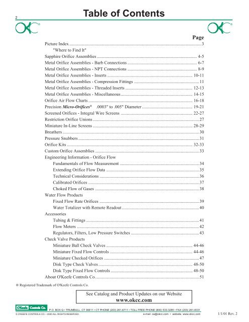
2Table of Contents®®PagePicture Index ......................................................................................................................3"Where to Find It"Sapphire <strong>Orifice</strong> <strong>Assemblies</strong> ......................................................................................... 4-5<strong>Metal</strong> <strong>Orifice</strong> <strong>Assemblies</strong> - Barb Connections .............................................................. 6-7<strong>Metal</strong> <strong>Orifice</strong> <strong>Assemblies</strong> - NPT Connections .............................................................. 8-9<strong>Metal</strong> <strong>Orifice</strong> <strong>Assemblies</strong> - Inserts ............................................................................ 10-11<strong>Metal</strong> <strong>Orifice</strong> <strong>Assemblies</strong> - Compression Fittings ..........................................................11<strong>Metal</strong> <strong>Orifice</strong> <strong>Assemblies</strong> - Threaded Inserts ............................................................ 12-13<strong>Metal</strong> <strong>Orifice</strong> <strong>Assemblies</strong> - Miscellaneous................................................................ 14-15<strong>Orifice</strong> Air Flow Charts ............................................................................................. 16-18Precision Micro-<strong>Orifice</strong>s ® .0003" to .005" Diameter ............................................. 19-21Screened <strong>Orifice</strong>s - Integral Wire Screens ................................................................ 22-27Restriction <strong>Orifice</strong> Unions ...............................................................................................27Miniature In-Line Screens ......................................................................................... 28-29Breathers ..........................................................................................................................30Pressure Snubbers ............................................................................................................31<strong>Orifice</strong> Kits ................................................................................................................ 32-33Custom <strong>Orifice</strong> <strong>Assemblies</strong> .............................................................................................33Engineering Information - <strong>Orifice</strong> FlowFundamentals of Flow Measurement .......................................................................34Extending <strong>Orifice</strong> Flow Data ...................................................................................35Technical Considerations .........................................................................................36Calibrated <strong>Orifice</strong>s ...................................................................................................37Choked Flow of Gases .............................................................................................38Water Flow ProductsFixed Flow Rate <strong>Orifice</strong>s .........................................................................................39Water Totalizer with Remote Readout .....................................................................40AccessoriesTubing & Fittings .....................................................................................................41Flow Meters .............................................................................................................42Regulators, Filters, Low Pressure Switches .............................................................43Check Valve ProductsMiniature Ball Check Valves ............................................................................. 44-46Miniature Fixed Flow <strong>Controls</strong> .......................................................................... 44-46Miniature Checked <strong>Orifice</strong>s .....................................................................................47Disk Type Check Valves .................................................................................... 48-50Disk Type Fixed Flow <strong>Controls</strong> ......................................................................... 48-50About <strong>O'Keefe</strong> <strong>Controls</strong> Co.............................................................................................51® Registered Trademark of <strong>O'Keefe</strong> <strong>Controls</strong> Co.See Catalog and Product Updates on our Websitewww.okcc.comP.O. BOX Q • TRUMBULL, CT 06611 • CT PHONE (203) 261-6711 • TOLL FREE PHONE (800) 533-3285 • FAX (203) 261-8331© O'KEEFE CONTROLS CO. • 2000 ALL RIGHTS RESERVED e-mail ca@okcc.com • website www.okcc.com1/1/01 Rev. 2
Picture Index"WHERE TO FIND IT"3Sapphire <strong>Orifice</strong> <strong>Assemblies</strong> – Pages 4-5<strong>Metal</strong> Barb <strong>Orifice</strong>s – Pages 6-7, 19-21TYPE APLASTIC INSERTPress fits into .125"/.126" BoreTYPE FPLASTIC INSERTPress fits into .132"/.133" BoreTYPE JHEX NIPPLE1/8" NPTTYPE T or WDUAL BARB1/16" or 1/8"TYPE M or NADAPTER10-32 by 1/16" or 1/8" BarbTYPE QBLEED PLUG10-32 ThreadType BT or BWADAPTER1/8" NPT by 1/16" or 1/8" BarbTYPE LADAPTER10-32 Thread by 1/16" BarbTYPE PBLEED PLUG10-32 ThreadTYPE SDUAL BARBFor 1/16" ID Tubing<strong>Orifice</strong> Inserts - Press Fit – Page 10<strong>Metal</strong> NPT <strong>Orifice</strong>s – Pages 8-9, 19-21TYPE AMFits into .126"/.127"Dia. HoleTYPE IAFits into .256"/.257"Dia. HoleTYPE IBFits into .0930"/.0940"Dia. HoleTYPE UFits into .279"/.280"Dia. HoleTYPE B or EHEX NIPPLE1/8" or 1/4" NPTTYPE D, G or HADAPTER1/8", 1/4" or 1/2" NPTTYPE BM or EMBLEED PLUG1/8" or 1/4" NPTTYPE BH or EHBLEED PLUG1/8" or 1/4" NPTThreaded Inserts – Pages 12-13<strong>Inc</strong>h or MetricPressure Snubbers – Page 31<strong>Orifice</strong> Kits – Pages 32-33<strong>Orifice</strong> kits provide a widerange of orifice sizes andflow rate. Kits are availablefor metal and sapphireorifices as well as forMicro-<strong>Orifice</strong>s ® .TYPE Z, ZMSet Screw StyleTYPE DP, GP or HP1/8", 1/4" or 1/2" NPTMiscellaneous <strong>Metal</strong> <strong>Orifice</strong>s – Pages 14-15Screen Products – Pages 28-29TYPE K4TUBE CONNECTION1/4" OD TubeTYPE R4CIRCULAR DISK.47" DiameterTYPE BFSSAE 45°FLARE FITTINGTYPE DSO or GSOSCREEN FITTING1/8" or 1/4" NPT AdapterTYPE FFSSCREEN FITTING10-32 Thread<strong>Orifice</strong>s with Integral Screens – Pages 22-27TYPE QSBBREATHER10-32 ThreadTYPE SSA, SSB or SSCBOUND SCREEN.211" .254" or .312" DiameterTYPE BMB or EMBBREATHER1/8" or 1/4" NPTTYPE BSHEX NIPPLE1/8" NPTTYPE QSBLEED PLUG10-32 ThreadTYPE BMMSBLEED PLUG1/8" NPTTYPE USDUAL SCREEN INSERTFits into .2795"/.2805" Dia. HoleBall Check Valves – Pages 44-46Checked <strong>Orifice</strong>s – Page 47Check Valve<strong>Orifice</strong>Screen Check Valve<strong>Orifice</strong>TYPE BLC or ELC1/8" or 1/4"NPTTYPE FFLC10-32 ThreadTYPE BILFC or EIJLC1/8" or 1/4"NPTTYPE FIFLCS10-32 ThreadFixed Flow <strong>Controls</strong> – Pages 44-50Accessories – Pages 41-43TYPE BLF or ELF1/8" or 1/4"NPTTYPE FFLF10-32 ThreadPrecisionPressureRegulators FlowmetersLow PressureAir SwitchesFittings® Registered Trademark of <strong>O'Keefe</strong> <strong>Controls</strong> Co.Disk Check Valves – Pages 48-50TYPE DOC or GOC1/8" or 1/4"NPTTYPE Y2C, Y4C or Y6C1/8", 1/4" or 3/8" NPTWaterTotalizerwith RemoteReadoutPage 40P.O. BOX Q • TRUMBULL, CT 06611 • CT PHONE (203) 261-6711 • TOLL FREE PHONE (800) 533-3285 • FAX (203) 261-8331© O'KEEFE CONTROLS CO. • 2000 ALL RIGHTS RESERVED e-mail ca@okcc.com • website www.okcc.com
4Sapphire <strong>Orifice</strong> <strong>Assemblies</strong>DescriptionThe restrictors incorporate a precision synthetic sapphire orificewhich is fitted within a main body. The sapphire orifice is a stable,accurate flow restrictor. Standard sizes range from .0012" to.0252" orifice diameter in 32 increments.Applications• Precision Flow Control - Gases or Liquids• Accurate Timing in Pneumatic or Hydraulic Circuits• Pressure Dividing Circuits and Pneumatic Resistance Bridges• Impedance MatchingAdvantages• Repeatable <strong>Orifice</strong> Size and Shape• Economical Precision <strong>Orifice</strong>• Low Clog ProbabilityOptions• Electroless nickel plating is available on Type S andType L. Add suffix EN.• Plating is for external appearance only.KitsSee page 33 for kit selection.General SpecificationsMaximum Operating Pressure – 100 psigFlow Direction – Preferred direction shown at right.Not recommended for reverse flow.Flow – See flow chart for air on page 18.<strong>Orifice</strong> Diameters – .0012" to .0252"<strong>Orifice</strong> Diameter Accuracy – ±.0003"C v Range – .00003 to .013 See page 18.Fluid Media – Air, Water, Gases and Liquids compatible withmaterials of construction.Dimensions – See drawings on page 5..0012" to .0252" DIA.LargeBore EndSapphire Sizes AvailableSize <strong>Orifice</strong> DiameterNumber mm In.3 .03 .00124 .04 .00165 .05 .00206 .06 .00247 .07 .00288 .08 .00319 .09 .003510 .10 .003911 .11 .004312 .12 .004713 .13 .005114 .14 .005515 .15 .005916 .16 .006317 .17 .006718 .18 .007120 .20 .007922 .22 .008724 .24 .009426 .26 .010228 .28 .011030 .30 .011832 .32 .012634 .34 .013436 .36 .014240 .40 .015744 .44 .017348 .48 .018952 .52 .020554 .54 .021358 .58 .022864 .64 .0252Type FConstructionSmallBore EndLargeBore EndType ASmallBore EndPart NumbersThe complete part number for an orifice assembly includes Type,Size Number, Body Material and Options.LargeBore EndType SSmallBore EndType JEXAMPLESize Number Body PartType (<strong>Orifice</strong> Dia.) Material Options NumberA 3 (.0012") Nylon — A-3-NYS 5 (.0020") Brass — S-5-BRS 5 (.0020") Brass EN S-5-BR-ENJ 10 (.0039") Brass — J-10-BRJ 10 (.0039") SS — J-10-SSLargeBore EndLargeBore EndType LSmallBore EndSmallBore EndLargeBore EndType PSmallBore EndType SF Type BTF, BWFThe restrictors should be installed with flow in the direction shown above. The flowdata provided in this catalog is measured for the flow direction shown above.P.O. BOX Q • TRUMBULL, CT 06611 • CT PHONE (203) 261-6711 • TOLL FREE PHONE (800) 533-3285 • FAX (203) 261-8331© O'KEEFE CONTROLS CO. • 2000 ALL RIGHTS RESERVED e-mail ca@okcc.com • website www.okcc.com
Type A.194"/.196" Dia.Dimensions.110" .196"Sapphire <strong>Orifice</strong> <strong>Assemblies</strong>Press Fit Into Bore.125"/.126" Dia..128"/.129" Dia..0012" to .0252" DIA.SpecificationsPLASTIC INSERTBody – Nylon<strong>Orifice</strong> – Synthetic SapphirePress fits into bore – .125"/.126"Standard <strong>Orifice</strong> Sizes – .0012" to .0252" Dia.5Type F.306".134"/.137" Dia.PLASTIC INSERTBody – Nylon<strong>Orifice</strong> – Synthetic SapphirePress fits into bore – .132"/.133"Fits into tubing – 1/8" ID Flexible PlasticStandard <strong>Orifice</strong> Sizes – .0012" to .0252" Dia.Type J1/8" NPT - both ends7/16" HEX.970"HEX NIPPLEBody – Brass or 303 SSInsert – Nylon<strong>Orifice</strong> – Synthetic SapphireThreads – 1/8" NPTStandard <strong>Orifice</strong> Sizes – .0012" to .0252" Dia.Type L10-32 x 1/16" barbType BTF1/8" NPT x 1/16" barbType BWF1/8" NPT x 1/8" barbThreadSealHEXWBarb for TubingType W HEXL .53" 1/4"BTF .86" 7/16"BWF .94" 7/16"ADAPTERBody – Brass Seal – Viton<strong>Orifice</strong> – Synthetic SapphireThread – 10-32 UNF, 1/8" NPTBarb – For 1/16" or 1/8" ID TubingOption – Electroless nickel plating on brass (Type L)Standard <strong>Orifice</strong> Sizes – .0012" to .0252" Dia.Type PType SType SF10-32 Straight ThreadSeal1/4" HEX9/32"Barb for 1/16" or 3/32"ID Tubing Both Ends3/16" HEX9/16"Barb for 1/16" ID TubingBoth Ends3/16" HEX9/16"No ConnectionThis EndBLEED PLUGBody – Brass Seal – Viton<strong>Orifice</strong> – Synthetic SapphireThread – 10-32 UNFStandard <strong>Orifice</strong> Sizes – .0012" to .0252" Dia.DUAL BARBBody – Brass<strong>Orifice</strong> – Synthetic SapphireBarb – For 1/16" or 3/32" ID TubingOption – Electroless nickel plating on brassStandard <strong>Orifice</strong> Sizes – .0012" to .0252" Dia.DUAL BARBBody – Brass<strong>Orifice</strong> – Synthetic SapphireBarb – For 1/16" ID TubingStandard <strong>Orifice</strong> Sizes – .0012" to .0252" Dia.P.O. BOX Q • TRUMBULL, CT 06611 • CT PHONE (203) 261-6711 • TOLL FREE PHONE (800) 533-3285 • FAX (203) 261-8331© O'KEEFE CONTROLS CO. • 2000 ALL RIGHTS RESERVED e-mail ca@okcc.com • website www.okcc.com
6DescriptionOne-piece construction of solid metal isemployed. <strong>Orifice</strong>s are accurately machined,thoroughly cleaned, and flow tested to exactingstandards. Sizes range from .004" to.063" orifice diameter. Special sizes can bemade to order.Applications• Precision Flow Control -Gases or Liquids• Speed <strong>Controls</strong> -Cylinders and Actuators• Accurate Timing in Pneumatic orHydraulic Circuits• Flow Restriction• Accurate Throttling• Snubbers - Gages and InstrumentsAdvantages• High Pressure Capability• Bi-directional Flow Compatibility• Economical Precision <strong>Orifice</strong>• Repeatable <strong>Orifice</strong> Size and Shape• Predictable Flow RateFlow Direction<strong>Metal</strong> <strong>Orifice</strong> <strong>Assemblies</strong> can be used forflow in either direction. The data on pages16 and 17 is for a flow direction as shown inthe right column on this page.KitsSee page 32 for kit selection.General SpecificationsMaximum Operating Pressure – 100 psigFlow – See flow chart for air onpages 16 and 17.<strong>Orifice</strong> Diameters – .004" to .063"<strong>Orifice</strong> Diameter Accuracy – ±.0003"C v Range – .00035 to .088See pages 16 and 17.Fluid Media – Air, Water, Gases andLiquids compatible with materials ofconstruction.Dimensions – See drawings on page 7.<strong>Metal</strong> <strong>Orifice</strong> <strong>Assemblies</strong>BARB CONNECTIONS<strong>Orifice</strong> SizeSize Dia. NumberNumber In. Range4 .00395 .00516 .0059 Type T7 .0071 Brass 4-358 .0079 303 SS 4-359 .009110 .0102 Type W11 .0110 Brass 4-6312 .0122 303 SS 4-6313 .013014 .0142 Type M15 .0150 Brass 4-3516 .016 303 SS 4-3517 .01718 .018 Type N19 .019 Brass 4-6320 .020 303 SS 4-6321 .02122 .022 Type Q23 .023 Brass 4-3524 .02425 .025 Type BT26 .026 Brass 4-3527 .027 303 SS 4-3528 .02829 .029 Type BW31 .031 Brass 4-6332 .032 303 SS 4-6333 .03335 .035 Type QX37 .037 Brass 4-3538 .038 303 SS 4-3539 .03940 .040 Type FM41 .041 Brass 4-6342 .042 303 SS 4-6343 .04347 .047 Type FF52 .052 Brass 4-6355 .055 303 SS 4-6360 .06063 .063Part NumbersConstructionType T or WType M or NType QType BT or BWType QXType FMType FFThe complete part number for an orifice assembly is composed of Type,Size Number, Body Material and Options.EXAMPLESize Body PartType Number Material Options NumberT 4 (.004") Brass – T-4-BRBW 16 (.016") SS – BW-16-SSM 24 (.024") Brass – M-24-BRP.O. BOX Q • TRUMBULL, CT 06611 • CT PHONE (203) 261-6711 • TOLL FREE PHONE (800) 533-3285 • FAX (203) 261-8331© O'KEEFE CONTROLS CO. • 2000 ALL RIGHTS RESERVED e-mail ca@okcc.com • website www.okcc.com
Type T or WDimensionsBarbs fit 1/16" or 1/8" ID Tubing.Type M or NBarbs fit 1/16" or 1/8" ID Tubing.Type QBarb For Plastic TubingHEXL10-32 Straight ThreadSealHEXL10-32 StraightThread1/4"HEX<strong>Metal</strong> <strong>Orifice</strong> <strong>Assemblies</strong>Barb forPlastic TubingBARB CONNECTIONSType Dim. L HEX BarbT .625" 3/16" 1/16"W .800" 1/4" 1/8"TypeMDim. L.530"HEX1/4"Barb1/16"N .610" 1/4" 1/8"SpecificationsDUAL BARBBody and <strong>Orifice</strong> – Brass or SSStandard <strong>Orifice</strong> Sizes –Type T – .004" to .035" Dia.Type W – .004" to .063" DiaADAPTERBody and <strong>Orifice</strong> – Brass or SSThread – 10-32 UNFThread Seal – VitonStandard <strong>Orifice</strong> Sizes –Type M – .004" to .035" Dia.Type N – .004" to .063" Dia.BLEED PLUGBody and <strong>Orifice</strong> – BrassThread – 10-32 UNFThread Seal – VitonStandard <strong>Orifice</strong> Sizes – .004" to .035" Dia.7Type BT or BWBarbs fit 1/16" or 1/8" ID Tubing.Type QXType FMType FF10-32ThreadSeal.280"1/8" NPT.335"LHEXBarb7-1/2°Seal 1/4" HEX10-32 Straight Thread10-32 StraightThread5/16" HEXSeal.440".500"Round10-32 StraightThread.312" Dia.10-32ThreadType Dim. L HEX BarbBTBW.800".880"7/16"7/16"1/16"1/8"ADAPTERBody and <strong>Orifice</strong> – Brass or SSThread – 1/8" NPTStandard <strong>Orifice</strong> Sizes –Type BT – .004" to .035" Dia.Type BW – .004" to .063" Dia.BLEED PLUGBody and <strong>Orifice</strong> – Brass or SSThread – 10-32 UNFThread Seal – VitonStandard <strong>Orifice</strong> Sizes – .004" to .035" Dia.ADAPTERBody and <strong>Orifice</strong> – Brass or SSThread – 10-32 UNFThread Seal – VitonStandard <strong>Orifice</strong> Sizes – .004" to .063" Dia.COUPLERBody and <strong>Orifice</strong> – Brass or SSThreads – 10-32 UNFStandard <strong>Orifice</strong> Sizes – .004" to .063" Dia.P.O. BOX Q • TRUMBULL, CT 06611 • CT PHONE (203) 261-6711 • TOLL FREE PHONE (800) 533-3285 • FAX (203) 261-8331© O'KEEFE CONTROLS CO. • 2000 ALL RIGHTS RESERVED e-mail ca@okcc.com • website www.okcc.com
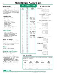
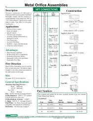
8DescriptionOne-piece construction of solid metal isemployed. <strong>Orifice</strong>s are accurately machined,thoroughly cleaned, and flow tested to exactingstandards. Sizes range from .004" to.125" orifice diameter. Special sizes can bemade to order.Applications• Precision Flow Control –Gases or Liquids• Speed <strong>Controls</strong> –Cylinders and Actuators• Accurate Timing in Pneumatic orHydraulic Circuits• Flow Restriction• Accurate Throttling• Snubbers - Gages and Instruments• Ultrasonic Sound SourcesAdvantages• High Pressure Capability• Bi-directional Flow Compatibility• Economical Precision <strong>Orifice</strong>• Repeatable <strong>Orifice</strong> Size and Shape• Predictable Flow RateFlow Direction<strong>Metal</strong> <strong>Orifice</strong> <strong>Assemblies</strong> can be used forflow in either direction. The data on pages16 and 17 is for a flow direction as shown inthe right column on this page.KitsSee page 32 for kit selection.General SpecificationsMaximum Operating Pressure –Brass 2000 psig303 SS 4000 psigFlow – See flow chart for air on pages 16 and 17.<strong>Orifice</strong> Diameters – .004" to .125" standard.Consult factory for other sizes.<strong>Orifice</strong> Diameter Accuracy – ±.0003"C v Range – .00035 to .37 See pages 16 and 17.Fluid Media – Air, Water, Gases and Liquidscompatible with materials of construction.Dimensions – See drawings on page 9.<strong>Metal</strong> <strong>Orifice</strong> <strong>Assemblies</strong>NPT CONNECTIONS<strong>Orifice</strong> SizeSize Dia. NumberNumber In. Range4 .00395 .00516 .00597 .00718 .00799 .009110 .010211 .011012 .012213 .013014 .014215 .015016 .01617 .01718 .01819 .01920 .02021 .02122 .02223 .02324 .02425 .02526 .02627 .02728 .02829 .02931 .03132 .03233 .03335 .03537 .03738 .03839 .03940 .04041 .04142 .04243 .04347 .04752 .05255 .05560 .06063 .06367 .06770 .07073 .07376 .07679 .07981 .08186 .08689 .08994 .09496 .096100 .100104 .104109 .109113 .113120 .120125 .125Part NumbersType B, E or VBrass 4-125303SS 4-125Type D, G, Hor VVBrass 4-125303SS 4-125Type BM or EMBrass 4-125303SS 4-125Type BH or EHBrass 4-125303SS 4-125Type BMMBrass 4-125303SS 4-125Type B, E or V<strong>Orifice</strong> diameter .021" or larger<strong>Orifice</strong> diameter .020" or smallerType D, G, H or VV<strong>Orifice</strong> diameter .021" or larger<strong>Orifice</strong> diameter .020" or smallerType BM or EMType BH or EHType BMMConstructionThe complete part number for an orifice assembly includes Type, Size Number,Body Material and Options.EXAMPLESize Body PartType Number Material Options NumberB 10 (.010") Brass – B-10-BRG 15 (.015") Brass – G-15-BRD 20 (.020") SS – D-20-SSP.O. BOX Q • TRUMBULL, CT 06611 • CT PHONE (203) 261-6711 • TOLL FREE PHONE (800) 533-3285 • FAX (203) 261-8331© O'KEEFE CONTROLS CO. • 2000 ALL RIGHTS RESERVED e-mail ca@okcc.com • website www.okcc.com
Type B, E or VDimensionsNPT - Both Ends<strong>Metal</strong> <strong>Orifice</strong> <strong>Assemblies</strong>NPT CONNECTIONSSpecificationsHEX NIPPLEBody and <strong>Orifice</strong> – Brass or SSThreads – 1/8", 1/4" or 3/8" NPTStandard <strong>Orifice</strong> Sizes –Brass – .004" to .125" Dia.303 SS – .004" to .125" Dia.9HEXLType Dim. L HEX NPTB .97" 7/16" 1/8"E 1.38" 9/16" 1/4"V 1.47" 11/16" 3/8"Type D, G, H or VVNPTNPTADAPTERBody and <strong>Orifice</strong> – Brass or SSThreads – 1/8", 1/4", 3/8" or 1/2" NPTStandard <strong>Orifice</strong> Sizes –Brass – .004" to .125" Dia.303 SS – .004" to .125" Dia.LHEXType Dim. L HEX NPTD .88" 9/16" 1/8"G 1.25" 3/4" 1/4"VV 1.52" 7/8" 3/8"H 1.69" 1-1/16" 1/2"Type BM or EMLBLEED PLUGBody and <strong>Orifice</strong> – Brass or SSThread – 1/8" or 1/4" NPTStandard <strong>Orifice</strong> Sizes –Brass – .004" to .125" Dia.303 SS – .004" to .125" Dia.NPTHEXType Dim. L HEX NPTBM .580" 7/16" 1/8"EM .800" 9/16" 1/4"Type BH or EHLInternalHEXBLEED PLUGBody and <strong>Orifice</strong> – Brass or SSThread – 1/8" or 1/4" NPTStandard <strong>Orifice</strong> Sizes –Brass – .004" to .125" Dia.303 SS – .004" to .125" Dia.NPTType Dim. L HEX NPTBH .30" 3/16" 1/8"EH .46" 1/4" 1/4"Type BMM.675"BLEED PLUGBody and <strong>Orifice</strong> – Brass or SSThread – 1/8" NPTStandard <strong>Orifice</strong> Sizes –Brass – .004" to .125" Dia.303 SS – .004" to .125" Dia.1/8" NPT7/16" HEXP.O. BOX Q • TRUMBULL, CT 06611 • CT PHONE (203) 261-6711 • TOLL FREE PHONE (800) 533-3285 • FAX (203) 261-8331© O'KEEFE CONTROLS CO. • 2000 ALL RIGHTS RESERVED e-mail ca@okcc.com • website www.okcc.com
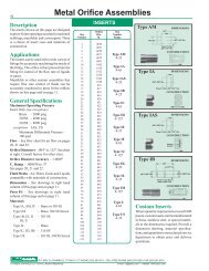
10DescriptionThe inserts shown on this page are designedto press-fit into openings accurately machinedin fittings, manifolds and custom parts. Thereis a choice of insert sizes and materials ofconstruction.ApplicationsThe inserts can be used with a wide variety offittings by accurately machining the inside ofthe fitting. The orifice is then pressed into thefitting for control of the flow rate of liquids orgases.Manifolds or other custom assemblies thatrequire flow rate control of fluids can beaccurately machined to press fit the orificesshown on this page and on the top of page 11.General SpecificationsMaximum Operating PressureInsert OnlyBrass – 2000 psig303SS – 4000 psig316SS – 4000 psigFlow – See flow chart for air flow on pages16, 17 and 18.<strong>Orifice</strong> Diameters – .004" to .063". Seechart at right. Consult factory for other sizes.<strong>Orifice</strong> Diameter Accuracy – ±.0003"C v Range – .00035 to .088See pages 16, 17 and 18.Fluid Media – Air, Water, Gases and Liquidscompatible with materials of construction.Dimensions – See drawings in right handcolumn of this page and on the top of page 11.Press Fit – See drawings in right handcolumn of this page and on the top of page 11.MaterialsType IA – BrassType I B, I E, I J – 303 SSI K, UType IC, I D – 316 SSType AM, I F, I H – Brass or 303 SSPart Numbers<strong>Metal</strong> <strong>Orifice</strong> <strong>Assemblies</strong><strong>Orifice</strong> SizeSize Dia. NumberNumber In. Range4 .00395 .00516 .00597 .00718 .00799 .009110 .010211 .011012 .012213 .013014 .014215 .015016 .01617 .01718 .01819 .01920 .02021 .02122 .02223 .02324 .02425 .02526 .02627 .02728 .02829 .02931 .03132 .03233 .03335 .03537 .03738 .03839 .03940 .04041 .04142 .04243 .04347 .04752 .05255 .05560 .06063 .063INSERTSFlow Direction<strong>Metal</strong> <strong>Orifice</strong> <strong>Assemblies</strong> can be usedfor flow in either direction. The data onpages 16, 17 and 18 is for a flow directionas shown in the right column on thispage and also on the top of page 11.The complete part number for an orifice assembly includes Type, Size Number,Body Material and Options.EXAMPLESize Body PartType Number Material Options NumberIB 6 (.006") SS – IB-6-SSAM 10 (.010") SS – AM-10-SSIA 20 (.020") Brass – IA-20-BRType AM4-35Type IA4-63Type IB4-25Type IC4-35Type U4-63Type ID4-125Type IE4-35Type IF4-63Type IH(metric)3-64see page 4Type I J4-125Type IK4-20Type AMType IAType IB.087"/.089" Dia.Type IC.1930"/.1935" Dia.Type U.258"/.259" Dia.DIMENSIONSCONSTRUCTION.156"Press Fit Into .256"/.257" Dia.CONSTRUCTION.250".125"Press Fit Into Bore.0930"/.0940" Dia.DIMENSIONSDIMENSIONSCONSTRUCTIONDIMENSIONSPress Fit Into Bore.1905"/.1910" Dia..125".280".276".196".145" Dia. .128"/.129" Dia.Press Fit Into.126"/.127" Dia..190"Press Fit Into .279"/.280" Bore.0945"/.0950" Dia..184"/.186" Dia.CONSTRUCTIONDIMENSIONS.2810".2815"19°CONSTRUCTIONP.O. BOX Q • TRUMBULL, CT 06611 • CT PHONE (203) 261-6711 • TOLL FREE PHONE (800) 533-3285 • FAX (203) 261-8331© O'KEEFE CONTROLS CO. • 2000 ALL RIGHTS RESERVED e-mail ca@okcc.com • website www.okcc.com
<strong>Metal</strong> <strong>Orifice</strong> <strong>Assemblies</strong>INSERTS11DIMENSIONS.440Type IDPress Fit Into.4125" / .4135"CONSTRUCTIONDIMENSIONS.060Type IEPress Fit Into.1230" / .1235"CONSTRUCTIONDIMENSIONS.270Type IFPress Fit Into.2475" / .2485"CONSTRUCTION.4140.1240.1250 Dia.2490.2495 Dia.4145 Dia Type IK10-32 ThreadSize Numbers 4-125See page 10 for orifice sizesDIMENSIONS.080.0995.1000 DiaType IC-PC4• For 1/4" OD <strong>Metal</strong> Tubing• Made from Swagelok PortConnector• <strong>Orifice</strong> size numbers 6-63Type IHPress Fit Into.0980" / .0990"CONSTRUCTIONSize Numbers 3-64 (metric)See page 4 for orifice sizesSize Numbers 4-35See page 10 for orifice sizesDIMENSIONS.27010-32 Thread.3800.3805 DiaType IJPress Fit Into.3785" / .3795"CONSTRUCTIONSize Numbers 4-125See page 10 for orifice sizesCOMPRESSION FITTINGS.97".37" .25"<strong>Orifice</strong>Insert.74"10-32 ThreadSize Numbers 4-63See page 10 for orifice sizesDIMENSIONS.062.031Spherical R..0615.0625 DiaPress Fit Into.0605" / .0610"CONSTRUCTIONSize Numbers 4-20See page 10 for orifice sizesPORT CONNECTORBody – 316 SS<strong>Orifice</strong> – 316 SSMax. Body Pressure – 4000 psigMax. Pressure Differential – 1000 psiin direction shownType IC-UT4• For 1/4" OD <strong>Metal</strong> Tubing• Made from Swagelok UnionTee Tube Fitting• <strong>Orifice</strong> size numbers 6-632.12"1.06" 9/16" Hex<strong>Orifice</strong>InsertUNION TEEBody – 316 SS<strong>Orifice</strong> – 316 SSMax. Body Pressure – 4000 psigMax. Pressure Differential – 200 psiType IC-MC4• For 1/4" OD <strong>Metal</strong> Tubing• Made from Swagelok MaleConnector Tube Fitting• <strong>Orifice</strong> size numbers 6-63<strong>Orifice</strong>Insert1/4" NPT1.49"9/16" HexMALE CONNECTORBody – 316 SS<strong>Orifice</strong> – 316 SSMax. Body Pressure – 4000 psigMax. Pressure Differential – 1000 psiin direction shownType IC-DM4• For 1/4" Applications• Made from 1/4" SwagelokVCR® Double Male Union• <strong>Orifice</strong> size numbers 6-63VCR® is a trademark of Cajon/A Swagelok Co.<strong>Orifice</strong>Insert1.55"5/8" HexCompression fitting Part Numbers – See part number format on Page 10DOUBLE MALE UNIONBody – 316 SS<strong>Orifice</strong> – 316 SSMax. Body Pressure – 4000 psigMax. Pressure Differential – 1000 psiin direction shownP.O. BOX Q • TRUMBULL, CT 06611 • CT PHONE (203) 261-6711 • TOLL FREE PHONE (800) 533-3285 • FAX (203) 261-8331© O'KEEFE CONTROLS CO. • 2000 ALL RIGHTS RESERVED e-mail ca@okcc.com • website www.okcc.com
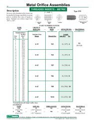
12<strong>Metal</strong> <strong>Orifice</strong> <strong>Assemblies</strong>DescriptionSet screw style threaded orifice inserts canbe installed in fittings, manifolds or customparts to establish flow rates of liquids orgases. Standard size orifices range from.006" to .063".THREADED INSERTS – METRICInternalHEXLengthThreadSize<strong>Orifice</strong>Type ZMBidirectionalFlowPART NUMBER SYSTEMTYPE ORIFICE THREADZM — SIZE NO. — SIZE — LENGTH NO. — MATERIALStandard Sizes<strong>Orifice</strong> Standard Size LengthSize Dia.* Range Thread Size mm (In.) No.No. In.6 .00597 .00718 .00799 .009110 .010211 .011012 .012213 .013014 .014215 .015016 .01617 .01718 .01819 .01920 .02021 .02122 .02223 .02324 .02425 .02526 .02627 .02728 .02829 .02931 .03132 .03233 .03335 .03537 .03738 .03839 .03940 .04041 .04142 .04243 .04347 .04752 .05255 .05560 .06063 .0636-35 M3 4 (.157) 46-35 M4 5 (.197) 56-63 M5 6 (.236) 66-63 M6 8 (.315) 86-63 M8 10 (.394) 106-63 M10 12 (.472) 12SS18-8 SS*Consult factory for larger orifice sizes.EXAMPLETYPE SIZE NO. THREAD SIZE LENGTH NO. MATERIAL1. ZM — 10 — M3 — 4 — SS(Type ZM) (.010" diameter) (4 mm length) (Stainless Steel)2. ZM — 31 — M6 — 8 — SS(Type ZM) (.031" diameter) (8 mm length) (Stainless Steel)P.O. BOX Q • TRUMBULL, CT 06611 • CT PHONE (203) 261-6711 • TOLL FREE PHONE (800) 533-3285 • FAX (203) 261-8331© O'KEEFE CONTROLS CO. • 2000 ALL RIGHTS RESERVED e-mail ca@okcc.com • website www.okcc.com
DescriptionSet screw style threaded orifice inserts canbe installed in fittings, manifolds or customparts to establish flow rates of liquids orgases. Standard size orifices range from.004" to .063". Both brass and 316 SSmaterials are offered.<strong>Metal</strong> <strong>Orifice</strong> <strong>Assemblies</strong>THREADED INSERTS – INCHInternalHEXLengthThreadSize<strong>Orifice</strong>Type ZBidirectionalFlowPART NUMBER SYSTEMTYPE ORIFICE THREADZ — SIZE NO. — SIZE — LENGTH NO. — MATERIAL13Standard Sizes<strong>Orifice</strong> Standard Size LengthSize Dia.* Range Thread Size In. No.No. In.4 .0039 Thread Size No.5 .00516 .00597 .00718 .00799 .009110 .010211 .011012 .012213 .013014 .014215 .015016 .01617 .01718 .01819 .01920 .02021 .02122 .02223 .02324 .02425 .02526 .02627 .02728 .02829 .02931 .03132 .03233 .03335 .03537 .03738 .03839 .03940 .04041 .04142 .04243 .04347 .04752 .05255 .05560 .06063 .0636 • 32 1/8 2 BR - BrassBrass 4-35 6 • 32 3/16 3SS 6-35 1/4 4 SS - 316SS8 • 32 1/8 2Brass 4-35 8 • 32 3/16 3SS 6-35 1/4 410 • 32 3/16 3Brass 4-63 10 • 32 1/4 4SS 6-63 3/8 61/4 • 20 1/4 4Brass 4-63 1/4 • 20 3/8 6SS 6-63 1/2 85/16 • 18 1/4 4Brass 4-63 5/16 • 18 3/8 6SS 6-63 1/2 83/8 • 16 3/8 6Brass 4-63 3/8 • 16 1/2 8SS 6-63*Consult factory for larger orifice sizes.EXAMPLETYPE SIZE NO. THREAD SIZE LENGTH NO. MATERIAL1. Z — 10 — 10 • 32 — 6 — BR(Type Z) (.010" diameter) (10 • 32 thread) (3/8" length) (Brass)2. Z — 31 — 1/4 • 20 — 4 — SS(Type Z) (.031" diameter) (1/4 • 20 thread) (1/4" length) (Stainless Steel)P.O. BOX Q • TRUMBULL, CT 06611 • CT PHONE (203) 261-6711 • TOLL FREE PHONE (800) 533-3285 • FAX (203) 261-8331© O'KEEFE CONTROLS CO. • 2000 ALL RIGHTS RESERVED e-mail ca@okcc.com • website www.okcc.com
14DescriptionPrecision orifice assemblies that adapt tocommon fittings used in process instrumentsand hydraulic systems are shown on pages14 and 15. Types K4, R4 and RG4 are usedwith nominal 1/4" tube fittings. Type BFS isfor 45° flare fittings and Type CFJ6 is for37° flare fittings. Type OD is a pipe adapter.Applications• Type K4 is a 1/4" OD Tube and is suitablefor use with a wide variety of compressionfittings.• Types R4 and RG4 are suitable for usewith face seal fittings.• Types BFS and CFJ6 are used in hydrauliccircuits, having SAE flare connections.Advantages• High Pressure Capability• Bi-directional Flow• Economical Precision <strong>Orifice</strong>• Repeatable <strong>Orifice</strong> Size and Shape• Predictable Flow RateGeneral SpecificationsFlow Direction – Suitable for flow in eitherdirection. Data on pages 16 and 17 is measuredfor flow direction shown in right columnof this page.Flow – See flow chart for air flow on pages16 and 17.C VRange – .00035 to .37See pages 16 and 17.<strong>Orifice</strong> Diameter Accuracy – ±.0003"Fluid Media – Air, Water, Gases and Liquidscompatible with materials of construction.Dimensions – See drawings on page 15.Materials of Construction –See page 15.Maximum Operating Pressure –See page 15.Part Numbers<strong>Metal</strong> <strong>Orifice</strong> <strong>Assemblies</strong>MISCELLANEOUS<strong>Orifice</strong> SizeSize Dia. NumberNumber In. Range4 .00395 .00516 .00597 .00718 .00799 .009110 .010211 .011012 .012213 .013014 .014215 .015016 .01617 .01718 .01819 .01920 .02021 .02122 .02223 .02324 .02425 .02526 .02627 .02728 .02829 .02931 .03132 .03233 .03335 .03537 .03738 .03839 .03940 .04041 .04142 .04243 .04347 .04752 .05255 .05560 .06063 .06367 .06770 .07073 .07376 .07679 .07981 .08186 .08689 .08994 .09496 .096100 .100104 .104109 .109113 .113120 .120125 .125The complete part number for an orifice assembly includes Type, Size Number,Body Material and Options.EXAMPLESize Body PartType Number Material Options NumberK4 6 (.006") Stainless Steel – K4-6-SSR4 13 (.013") Stainless Steel – R4-13-SSBFS 35 (.035") Brass – BFS-35-BRCFJ6 104 (.104") Stainless Steel – CFJ6-104-SSType K44-35Type R44-125Type RG44-125Type BFS4-125Type CFJ64-125Type OD4-125Type K4Type R4Type RG4Type BFSType CFJ6Type ODConstructionP.O. BOX Q • TRUMBULL, CT 06611 • CT PHONE (203) 261-6711 • TOLL FREE PHONE (800) 533-3285 • FAX (203) 261-8331© O'KEEFE CONTROLS CO. • 2000 ALL RIGHTS RESERVED e-mail ca@okcc.com • website www.okcc.com
17<strong>Metal</strong> <strong>Orifice</strong> Air Flow – SLPM<strong>Orifice</strong>Diameter 0.004 0.005 0.006 0.007 0.008 0.009 0.010 0.011 0.012 0.013 0.014 0.015 0.016 0.017 0.018 0.019 0.020 0.021 0.022 0.023 0.024 0.025 0.026 0.027 0.028 0.029 0.031 0.032 0.033<strong>Inc</strong>hesSizeNumber 4 5 6 7 8 9 10 11 12 13 14 15 16 17 18 19 20 21 22 23 24 25 26 27 28 29 31 32 33C v 0.00035 0.00061 0.00086 0.0012 0.0015 0.0019 0.0025 0.0028 0.0034 0.0038 0.0043 0.0050 0.0055 0.0067 0.0073 0.0080 0.0088 0.0096 0.011 0.012 0.013 0.014 0.016 0.017 0.018 0.019 0.022 0.024 0.0251 0.035 0.064 0.086 0.127 0.170 0.226 0.280 0.308 0.398 0.45 0.52 0.61 0.66 0.77 0.86 0.96 1.05 1.13 1.29 1.41 1.54 1.67 1.91 1.95 2.21 2.39 2.65 2.88 3.035 0.09 0.16 0.21 0.30 0.40 0.52 0.65 0.71 0.92 1.06 1.21 1.41 1.54 1.76 1.98 2.22 2.47 2.65 2.97 3.24 3.53 3.83 4.34 4.44 4.94 5.31 5.86 6.42 6.8010 0.12 0.22 0.31 0.43 0.57 0.74 0.93 1.01 1.29 1.48 1.68 1.95 2.01 2.26 2.54 2.83 3.16 3.53 4.33 4.75 5.18 5.55 6.15 6.43 7.18 7.83 8.63 9.40 9.9815 0.16 0.28 0.39 0.54 0.72 0.93 1.17 1.26 1.62 1.85 2.10 2.44 2.50 2.85 3.23 3.57 4.01 4.41 5.35 5.93 6.43 6.95 7.58 7.95 8.78 9.58 10.6 11.6 12.320 0.19 0.33 0.46 0.65 0.85 1.10 1.38 1.49 1.92 2.19 2.49 2.87 2.97 3.40 3.86 4.26 4.84 5.22 6.35 6.95 7.58 8.15 8.90 9.28 10.3 11.2 12.4 13.5 14.325 0.22 0.39 0.53 0.75 0.98 1.27 1.59 1.71 2.20 2.50 2.86 3.28 3.42 3.92 4.45 4.91 5.59 6.01 7.30 7.95 8.65 9.38 10.2 10.7 11.7 12.8 14.2 15.4 16.330 0.25 0.44 0.60 0.85 1.12 1.43 1.80 1.93 2.47 2.82 3.21 3.69 3.87 4.43 5.03 5.56 6.33 6.81 8.23 8.98 9.75 10.6 11.5 12.0 13.2 14.4 15.9 17.3 18.440 0.30 0.54 0.74 1.05 1.38 1.77 2.21 2.37 3.04 3.45 3.93 4.51 4.78 5.47 6.21 6.85 7.81 8.42 10.1 11.0 12.0 13.0 14.1 14.7 16.1 17.5 19.4 21.1 22.550 0.36 0.65 0.88 1.26 1.65 2.10 2.62 2.80 3.58 4.07 4.64 5.31 5.70 6.51 7.40 8.15 9.26 10.0 11.9 13.0 14.2 15.4 16.6 17.3 19.0 20.7 22.9 25.0 26.660 0.42 0.75 1.02 1.46 1.91 2.42 3.02 3.23 4.13 4.70 5.34 6.13 6.61 7.56 8.58 9.46 10.7 11.6 13.8 15.0 16.4 17.7 19.2 20.0 21.9 23.8 26.4 28.8 30.770 0.48 0.86 1.16 1.67 2.17 2.75 3.43 3.66 4.68 5.32 6.05 6.96 7.53 8.61 9.77 10.8 12.2 13.2 15.6 17.0 18.5 20.1 21.7 22.7 24.8 27.0 30.0 32.7 34.980 0.54 0.96 1.30 1.87 2.43 3.08 3.83 4.09 5.23 5.95 6.77 7.79 8.46 9.67 11.0 12.1 13.7 14.9 17.5 19.0 20.7 22.5 24.2 25.3 27.7 30.2 33.6 36.7 39.090 0.60 1.07 1.44 2.08 2.69 3.40 4.23 4.51 5.78 6.58 7.49 8.62 9.38 10.7 12.2 13.4 15.2 16.5 19.3 21.0 22.9 24.9 26.8 28.0 30.7 33.5 37.2 40.6 43.2100 0.66 1.17 1.58 2.28 2.95 3.72 4.63 4.94 6.33 7.22 8.21 9.46 10.3 11.8 13.4 14.7 16.6 18.0 21.1 23.0 25.1 27.4 29.4 30.8 33.7 36.8 40.9 44.6 47.55 0.053 0.096 0.129 0.191 0.253 0.332 0.406 0.450 0.582 0.661 0.773 0.899 0.977 1.14 1.28 1.41 1.55 1.70 1.90 2.10 2.30 2.48 2.74 2.83 3.16 3.41 3.78 4.12 4.3210 0.069 0.124 0.168 0.246 0.324 0.421 0.519 0.564 0.730 0.834 0.972 1.12 1.24 1.41 1.58 1.79 1.96 2.18 2.44 2.68 2.89 3.13 3.44 3.58 4.00 4.30 4.77 5.16 5.4315 0.075 0.134 0.185 0.268 0.351 0.455 0.566 0.614 0.792 0.902 1.07 1.22 1.35 1.55 1.75 1.94 2.19 2.32 2.61 2.85 3.12 3.34 3.65 3.78 4.20 4.51 5.05 5.45 5.7220 0.075 0.134 0.185 0.268 0.351 0.455 0.566 0.614 0.792 0.902 1.07 1.22 1.35 1.55 1.75 1.94 2.19 2.32 2.61 2.85 3.12 3.34 3.65 3.78 4.20 4.51 5.05 5.45 5.7230 0.075 0.134 0.185 0.268 0.351 0.455 0.566 0.614 0.792 0.902 1.07 1.22 1.35 1.55 1.75 1.94 2.19 2.32 2.61 2.85 3.12 3.34 3.65 3.78 4.20 4.51 5.05 5.45 5.72Choked FlowSupply Pressure – psigVacuum LevelIn. Hg.Choked FlowSupply Pressure – psig<strong>Orifice</strong>Diameter 0.035 0.037 0.038 0.039 0.040 0.041 0.042 0.043 0.047 0.052 0.055 0.060 0.063 0.067 0.070 0.073 0.076 0.079 0.081 0.086 0.089 0.094 0.096 0.100 0.104 0.109 0.113 0.120 0.125<strong>Inc</strong>hesSizeNumber 35 37 38 39 40 41 42 43 47 52 55 60 63 67 70 73 76 79 81 86 89 94 96 100 104 109 113 120 125Cv 0.028 0.031 0.032 0.033 0.036 0.038 0.039 0.041 0.048 0.059 0.068 0.081 0.088 0.10 0.11 0.12 0.13 0.14 0.15 0.17 0.18 0.20 0.21 0.23 0.25 0.27 0.31 0.34 0.371 3.48 3.83 4.13 4.46 4.60 4.67 4.99 5.36 6.43 8.04 9.40 11.2 12.2 14.2 15.9 16.9 18.5 20.3 21.7 23.5 25.4 28.4 30.1 32.9 35.5 39.6 43.1 47.8 50.15 7.67 8.48 9.09 9.70 10.2 10.6 11.3 12.1 14.2 17.6 20.3 23.9 26.1 30.3 33.8 36.1 39.4 43.1 46.0 51.1 54.9 61.9 65.0 70.8 76.6 84.8 92.1 102 10810 10.6 11.8 12.5 13.6 14.4 14.8 15.6 16.8 19.4 24.5 27.1 32.2 35.2 40.7 45.6 48.5 52.9 57.3 61.6 67.9 72.3 81.0 85.5 92.3 102 112 118 135 14815 13.1 14.5 15.4 16.7 17.7 18.2 19.1 20.4 23.6 29.7 32.9 39.0 42.6 49.3 55.3 58.8 64.0 69.4 74.5 82.1 87.3 97.8 103 111 123 135 143 163 17820 15.3 17.0 18.1 19.6 20.9 21.4 22.5 24.0 27.7 35.0 38.7 45.9 50.1 58.0 65.0 69.0 75.3 81.4 87.3 95.6 102 114 121 130 144 158 167 190 21025 17.7 19.6 20.8 22.6 24.0 24.7 25.9 27.6 31.9 40.3 44.6 52.8 57.7 66.7 74.7 79.3 86.4 93.5 100 110 117 131 138 149 164 180 191 219 24130 20.0 22.2 23.6 25.6 27.2 28.0 29.4 31.3 36.0 45.6 50.4 59.7 65.2 75.4 84.3 89.5 97.4 105 113 125 132 148 156 168 185 204 216 248 27340 24.8 27.4 31.7 31.6 33.6 34.6 36.3 38.7 44.5 56.3 62.2 73.6 80.3 92.7 104 110 120 129 139 153 162 181 191 207 228 251 267 306 33750 29.5 32.6 34.8 37.6 40.1 41.3 43.3 46.0 52.9 66.9 74.0 87.4 95.4 110 123 131 142 153 164 181 192 215 227 247 272 299 317 364 40160 34.3 38.0 40.6 43.8 46.7 48.1 50.3 53.5 61.5 77.7 85.8 101 110 127 142 151 164 177 189 210 223 250 264 286 315 347 368 422 46570 39.2 43.3 46.3 50.0 53.3 55.0 57.4 61.0 70.0 88.4 97.6 115 126 145 162 171 186 202 216 240 254 285 301 327 360 396 421 482 53180 44.0 48.7 52.1 56.2 60.0 61.9 64.5 68.5 78.6 99.1 109 129 141 162 181 191 209 227 242 269 285 320 338 367 404 445 472 541 59690 50.0 54.2 57.8 62.4 66.7 68.9 71.5 76.0 87.2 109 121 143 156 179 200 211 231 251 268 298 316 354 374 406 447 492 522 598 660100 53.9 59.6 63.7 68.7 73.5 77.3 78.6 83.5 95.8 120 133 156 171 196 221 234 255 277 296 329 349 392 413 449 494 544 578 662 7295 4.92 5.40 5.81 6.29 6.76 6.82 7.29 7.67 9.08 11.3 12.4 14.8 17.1 20.0 22.5 23.9 26.0 28.3 30.2 33.2 35.9 40.1 41.8 45.3 49.0 53.9 57.9 65.3 70.910 6.18 6.78 7.29 7.85 8.31 8.50 9.08 9.58 11.1 13.9 15.4 18.2 21.2 24.4 27.2 29.9 32.5 35.3 37.7 41.5 44.8 50.0 52.1 56.6 61.2 67.2 72.2 81.4 88.415 6.50 7.17 7.63 8.22 8.66 8.87 9.46 10.0 11.6 14.4 15.9 18.6 22.1 25.5 28.4 31.2 33.9 36.8 39.4 43.3 46.7 52.1 54.4 59.0 63.8 70.1 75.3 84.9 92.220 6.50 7.17 7.63 8.22 8.66 8.87 9.46 10.0 11.6 14.4 15.9 18.6 22.1 25.5 28.4 31.2 33.9 36.8 39.4 43.3 46.7 52.1 54.4 59.0 63.8 70.1 75.3 84.9 92.230 6.50 7.17 7.63 8.22 8.66 8.87 9.46 10.0 11.6 14.4 15.9 18.6 22.1 25.5 28.4 31.2 33.9 36.8 39.4 43.3 46.7 52.1 54.4 59.0 63.8 70.1 75.3 84.9 92.2Vacuum LevelIn. Hg.Standard Conditions 70°F, 14.7 psia SCFH – Standard Cu. Ft. Per Hour Above data obtained with Type B restrictor. Flow rates for other metal restrictorsareSLPM – Standard Liters Per Minute essentially the same as for Type B. Above data supercedes previous publications.P.O. BOX Q • TRUMBULL, CONNECTICUT 06611 • CT PHONE (203) 261-6711 • TOLL FREE PHONE (800) 533-3285 • FAX (203) 261-8331© O'KEEFE CONTROLS CO. • 2000 ALL RIGHTS RESERVED • e-mail ca@okcc.com • website www.okcc.com
18Sapphire <strong>Orifice</strong> Air Flow – SLPM<strong>Orifice</strong>Diameter 0.0012 0.0016 0.0020 0.0024 0.0028 0.0031 0.0035 0.0039 0.0043 0.0047 0.0051 0.0055 0.0059 0.0063 0.0067 0.0071 0.0079 0.0087 0.0094 0.0102 0.0110 0.0118 0.0126 0.0134 0.0142 0.0157 0.0173 0.0189 0.0205 0.0213 0.0228 0.0252<strong>Inc</strong>hesSizeNumber 3 4 5 6 7 8 9 10 11 12 13 14 15 16 17 18 20 22 24 26 28 30 32 34 36 40 44 48 52 54 58 64C v 0.000030 0.000053 0.000090 0.00012 0.00017 0.00022 0.00028 0.00035 0.00042 0.00050 0.00061 0.00071 0.00084 0.00094 0.0011 0.0012 0.0015 0.0018 0.0021 0.0024 0.0028 0.0032 0.0036 0.0040 0.0046 0.0057 0.0067 0.0080 0.0091 0.010 0.011 0.0131 0.003 0.005 0.010 0.014 0.020 0.025 0.034 0.040 0.050 0.058 0.068 0.080 0.095 0.106 0.120 0.139 0.161 0.194 0.259 0.275 0.300 0.340 0.393 0.446 0.499 0.677 0.822 0.965 1.10 1.12 1.38 1.695 0.009 0.013 0.027 0.036 0.047 0.059 0.076 0.093 0.108 0.136 0.159 0.192 0.223 0.256 0.273 0.313 0.350 0.430 0.584 0.623 0.695 0.800 0.933 1.06 1.20 1.51 1.81 2.16 2.50 2.57 3.26 4.0610 0.010 0.016 0.036 0.049 0.065 0.082 0.107 0.132 0.164 0.193 0.228 0.264 0.308 0.357 0.382 0.430 0.480 0.590 0.830 0.868 0.968 1.09 1.27 1.45 1.63 2.01 2.43 2.90 3.32 3.45 4.43 5.5815 0.014 0.021 0.046 0.062 0.082 0.104 0.134 0.166 0.205 0.240 0.285 0.329 0.386 0.443 0.482 0.535 0.613 0.755 1.05 1.11 1.24 1.42 1.63 1.85 2.09 2.56 3.08 3.69 4.26 4.43 5.55 7.0820 0.016 0.025 0.055 0.074 0.099 0.125 0.159 0.197 0.243 0.284 0.337 0.390 0.457 0.525 0.569 0.635 0.730 0.910 1.25 1.32 1.48 1.70 1.95 2.20 2.48 3.04 3.64 4.36 5.06 5.31 6.55 8.3325 0.019 0.030 0.063 0.087 0.115 0.144 0.184 0.229 0.280 0.327 0.389 0.450 0.526 0.605 0.654 0.733 0.843 1.05 1.44 1.52 1.70 1.95 2.24 2.52 2.84 3.50 4.19 5.03 5.81 6.11 7.53 9.5530 0.022 0.034 0.072 0.098 0.132 0.164 0.208 0.260 0.317 0.370 0.440 0.511 0.595 0.685 0.710 0.838 0.958 1.19 1.63 1.69 1.91 2.19 2.52 2.84 3.19 3.96 4.75 5.69 6.57 6.90 8.48 10.740 0.027 0.043 0.089 0.122 0.163 0.203 0.257 0.321 0.390 0.456 0.543 0.632 0.734 0.845 0.880 1.04 1.18 1.47 2.02 2.11 2.35 2.67 3.07 3.46 3.90 4.89 5.86 7.02 8.10 8.50 10.4 13.150 0.032 0.052 0.106 0.147 0.195 0.241 0.306 0.383 0.463 0.542 0.652 0.753 0.872 1.00 1.05 1.24 1.41 1.75 2.39 2.50 2.78 3.16 3.63 4.08 4.59 5.83 6.96 8.35 9.63 10.1 12.3 15.560 0.037 0.061 0.123 0.171 0.227 0.280 0.356 0.445 0.536 0.630 0.751 0.875 1.01 1.16 1.23 1.45 1.64 2.03 2.77 2.89 3.20 3.63 4.17 4.69 5.29 6.77 8.10 9.69 11.1 11.7 14.2 17.970 0.042 0.070 0.141 0.195 0.259 0.318 0.403 0.507 0.609 0.717 0.855 0.996 1.15 1.32 1.40 1.66 1.87 2.31 3.14 3.28 3.62 4.12 4.72 5.31 5.99 7.71 9.23 11.0 12.7 13.3 16.0 20.280 0.047 0.080 0.158 0.200 0.292 0.357 0.453 0.569 0.683 0.804 0.959 1.12 1.28 1.48 1.57 1.86 2.09 2.59 3.51 3.66 4.04 4.68 5.28 5.93 6.69 8.65 10.4 12.3 14.3 14.8 17.9 22.690 0.053 0.089 0.175 0.244 0.324 0.396 0.502 0.632 0.757 0.891 1.06 1.24 1.42 1.64 1.75 2.06 2.32 2.87 3.89 4.05 4.47 5.07 5.83 6.56 7.41 9.60 11.5 13.7 15.7 16.4 19.7 24.9100 0.058 0.098 0.193 0.269 0.356 0.435 0.551 0.692 0.830 0.978 1.17 1.36 1.56 1.80 1.92 2.27 2.55 3.15 4.26 4.44 4.89 5.57 6.38 7.18 8.12 10.6 12.6 15.0 17.2 18.0 21.6 27.35 0.003 0.006 0.014 0.020 0.028 0.036 0.047 0.057 0.073 0.085 0.100 0.116 0.137 0.156 0.169 0.199 0.229 0.277 0.377 0.401 0.451 0.510 0.591 0.673 0.764 0.982 1.16 1.38 1.61 1.64 2.13 2.6110 0.004 0.008 0.018 0.027 0.036 0.046 0.061 0.073 0.093 0.109 0.128 0.149 0.175 0.200 0.217 0.253 0.292 0.352 0.482 0.503 0.556 0.638 0.734 0.833 0.955 1.26 1.51 1.80 2.06 2.11 2.55 3.1915 0.006 0.010 0.021 0.030 0.040 0.050 0.065 0.079 0.100 0.117 0.138 0.159 0.188 0.214 0.235 0.269 0.320 0.390 0.525 0.554 0.626 0.711 0.818 0.921 1.07 1.39 1.65 1.99 2.31 2.39 2.77 3.4820 0.006 0.010 0.021 0.030 0.040 0.050 0.065 0.079 0.100 0.117 0.138 0.159 0.188 0.214 0.235 0.269 0.320 0.390 0.525 0.554 0.626 0.711 0.818 0.921 1.07 1.39 1.65 1.99 2.31 2.39 2.77 3.4830 0.006 0.010 0.021 0.030 0.040 0.050 0.065 0.079 0.100 0.117 0.138 0.159 0.188 0.214 0.235 0.269 0.320 0.390 0.525 0.554 0.626 0.711 0.818 0.921 1.07 1.39 1.65 1.99 2.31 2.39 2.77 3.48Choked FlowSupply Pressure – psig<strong>Orifice</strong>Diameter 0.0012 0.0016 0.0020 0.0024 0.0028 0.0031 0.0035 0.0039 0.0043 0.0047 0.0051 0.0055 0.0059 0.0063 0.0067 0.0071 0.0079 0.0087 0.0094 0.0102 0.0110 0.0118 0.0126 0.0134 0.0142 0.0157 0.0173 0.0189 0.0205 0.0213 0.0228 0.0252<strong>Inc</strong>hesSizeNumber 3 4 5 6 7 8 9 10 11 12 13 14 15 16 17 18 20 22 24 26 28 30 32 34 36 40 44 48 52 54 58 64C v 0.000030 0.000053 0.000090 0.00012 0.00017 0.00022 0.00028 0.00035 0.00042 0.00050 0.00061 0.00071 0.00084 0.00094 0.0011 0.0012 0.0015 0.0018 0.0021 0.0024 0.0028 0.0032 0.0036 0.0040 0.0046 0.0057 0.0067 0.0080 0.0091 0.010 0.011 0.0131 0.007 0.011 0.021 0.030 0.042 0.053 0.072 0.085 0.106 0.123 0.144 0.169 0.201 0.225 0.254 0.294 0.341 0.411 0.549 0.583 0.636 0.720 0.833 0.945 1.06 1.43 1.74 2.04 2.33 2.37 2.92 3.585 0.019 0.027 0.056 0.075 0.100 0.124 0.161 0.197 0.228 0.288 0.337 0.407 0.471 0.542 0.577 0.663 0.740 0.911 1.24 1.32 1.47 1.70 1.98 2.25 2.53 3.20 3.83 4.58 5.30 5.44 6.90 8.6010 0.021 0.034 0.076 0.104 0.138 0.174 0.227 0.280 0.347 0.409 0.483 0.559 0.653 0.756 0.809 0.911 1.02 1.25 1.76 1.84 2.05 2.31 2.69 3.07 3.45 4.26 5.15 6.14 7.03 7.31 9.39 11.815 0.030 0.044 0.097 0.131 0.174 0.220 0.284 0.352 0.434 0.508 0.604 0.697 0.818 0.939 1.02 1.13 1.30 1.60 2.22 2.35 2.63 3.01 3.45 3.92 4.43 5.42 6.53 7.82 9.03 9.39 11.8 15.020 0.034 0.053 0.117 0.157 0.210 0.265 0.337 0.417 0.515 0.602 0.714 0.826 0.968 1.11 1.21 1.35 1.55 1.93 2.65 2.80 3.14 3.60 4.13 4.66 5.25 6.44 7.71 9.24 10.7 11.3 13.9 17.625 0.040 0.064 0.133 0.184 0.244 0.305 0.390 0.485 0.593 0.693 0.824 0.953 1.11 1.28 1.39 1.55 1.79 2.22 3.05 3.22 3.60 4.13 4.75 5.34 6.02 7.42 8.88 10.7 12.3 12.9 16.0 20.230 0.046 0.072 0.152 0.208 0.280 0.347 0.441 0.551 0.672 0.784 0.932 1.08 1.26 1.45 1.50 1.78 2.03 2.52 3.45 3.58 4.05 4.64 5.34 6.02 6.76 8.39 10.1 12.1 13.9 14.6 18.0 22.740 0.057 0.091 0.189 0.258 0.345 0.430 0.544 0.680 0.826 0.966 1.15 1.34 1.56 1.79 1.86 2.20 2.50 3.11 4.28 4.47 4.98 5.66 6.50 7.33 8.26 10.4 12.4 14.9 17.2 18.0 22.0 27.850 0.068 0.110 0.225 0.311 0.413 0.511 0.648 0.811 0.981 1.15 1.38 1.60 1.85 2.13 2.22 2.63 2.99 3.71 5.06 5.30 5.89 6.69 7.69 8.64 9.72 12.4 14.7 17.7 20.4 21.4 26.1 32.860 0.079 0.129 0.261 0.362 0.481 0.593 0.754 0.943 1.14 1.33 1.59 1.85 2.14 2.46 2.61 3.07 3.47 4.30 5.87 6.12 6.78 7.69 8.83 9.94 11.2 14.3 17.2 20.5 23.5 24.8 30.1 37.970 0.089 0.149 0.299 0.413 0.549 0.674 0.854 1.07 1.29 1.52 1.81 2.11 2.43 2.80 2.97 3.52 3.96 4.89 6.65 6.95 7.67 8.73 10.0 11.3 12.7 16.3 19.6 23.3 26.9 28.2 33.9 42.880 0.100 0.168 0.335 0.424 0.619 0.756 0.960 1.21 1.45 1.70 2.03 2.37 2.72 3.13 3.33 3.94 4.43 5.49 7.44 7.75 8.56 9.75 11.2 12.6 14.2 18.3 22.0 26.1 30.3 31.4 37.9 47.990 0.111 0.188 0.371 0.517 0.686 0.839 1.06 1.34 1.60 1.89 2.25 2.62 3.01 3.47 3.71 4.36 4.92 6.08 8.24 8.58 9.47 10.7 12.4 13.9 15.7 20.3 24.4 29.0 33.3 34.7 41.7 52.8100 0.122 0.208 0.409 0.570 0.754 0.922 1.17 1.47 1.76 2.07 2.47 2.88 3.30 3.81 4.07 4.81 5.40 6.67 9.03 9.41 10.4 11.8 13.5 15.2 17.2 22.5 26.7 31.8 36.4 38.1 45.8 57.85 0.007 0.013 0.029 0.043 0.059 0.076 0.100 0.121 0.154 0.180 0.212 0.246 0.290 0.331 0.358 0.422 0.485 0.587 0.799 0.850 0.956 1.08 1.25 1.43 1.62 2.08 2.46 2.92 3.41 3.47 4.51 5.5310 0.009 0.018 0.039 0.057 0.076 0.098 0.128 0.155 0.197 0.231 0.271 0.316 0.371 0.424 0.460 0.536 0.619 0.746 1.02 1.07 1.18 1.35 1.56 1.76 2.02 2.67 3.19 3.81 4.36 4.47 5.40 6.7615 0.012 0.020 0.045 0.063 0.085 0.107 0.138 0.168 0.212 0.248 0.292 0.337 0.398 0.453 0.498 0.570 0.678 0.826 1.11 1.17 1.33 1.51 1.73 1.95 2.26 2.95 3.50 4.22 4.89 5.06 5.87 7.3720 0.012 0.020 0.045 0.063 0.085 0.107 0.138 0.168 0.212 0.248 0.292 0.337 0.398 0.453 0.498 0.570 0.678 0.826 1.11 1.17 1.33 1.51 1.73 1.95 2.26 2.95 3.50 4.22 4.89 5.06 5.87 7.3730 0.012 0.020 0.045 0.063 0.085 0.107 0.138 0.168 0.212 0.248 0.292 0.337 0.398 0.453 0.498 0.570 0.678 0.826 1.11 1.17 1.33 1.51 1.73 1.95 2.26 2.95 3.50 4.22 4.89 5.06 5.87 7.37Vacuum LevelIn. Hg.Choked FlowSupply Pressure – psigVacuum LevelIn. Hg.Sapphire <strong>Orifice</strong> Air Flow – SCFHStandard Conditions 70°F, 14.7 psia SCFH – Standard Cu. Ft. Per Hour Above data obtained with Type S restrictor. Flow rates for Type A, BTF, BWF, F, J,SLPM – Standard Liters Per Minute L, P, and SF restrictors are essentially the same as for Type S.Above data supercedes previous publications.P.O. BOX Q • TRUMBULL, CONNECTICUT 06611 • CT PHONE (203) 261-6711 • TOLL FREE PHONE (800) 533-3285 • FAX (203) 261-8331© O'KEEFE CONTROLS CO. • 2000 ALL RIGHTS RESERVED • e-mail ca@okcc.com • website www.okcc.com
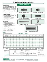
DescriptionThe Precision Micro-<strong>Orifice</strong>s ® are constructedof brass or stainless steel withorifice sizes from .0003" to .005" diameter.The orifices are used to accurately metervery low flow rates of gases or liquids.Optional stainless steel screens are availableto protect the tiny orifices from minutecontamination particles.Precision Micro-<strong>Orifice</strong>s ®.0003" to .0050" DIA.Type BLP - 1/8" NPT NippleType QXLP - 10-32 Bleed Plug19Applications• Precision metering of very low flowrates – gases or liquids• Standard for flow or leak rates• Accurate timing in pneumatic orhydraulic circuits• Flow limitingFeatures• High temperature capability(Type BLP, IBLP)• High pressure capability(Type BLP)• Bi-directional flow• High accuracy• NIST traceable• Optional in-line screens available(except Type IBLP)• <strong>Orifice</strong> calibration availableKitsSee page 33 for kit selection.Micro-<strong>Orifice</strong>s ®Size <strong>Orifice</strong> Air FlowNumber Dia. @ 25 psigIn.sccmType MLP - 10-32 x 1/16" BarbDimensionsType BLPType MLPType QXLP1/8" NPT7/16"HEX.97"10-32 Straight ThreadSealBarb for 1/16"ID Plastic Tubing1/4" HEX.530".335"7-1/2°ConstructionType BLPType MLPType QXLPType IBLP - Insert0C .0003 1.240E .0005 3.440G .0007 6.741 .0010 14.01E .0015 31.02 .0020 55.02E .0025 86.03 .0030 1243E .0035 1684* .0040 2205* .0050 344* This size for stainless steel only.See pages 6 through 9 for brass orifices.® Registered Trademark of <strong>O'Keefe</strong> <strong>Controls</strong> Co.Type IBLP.087"/.089" Dia.1/4"Seal HEX10-32 Straight Thread.250".125"Press fits into.0930"/.0940" Dia. Bore.0945"/.0950" Dia.Type IBLPP.O. BOX Q • TRUMBULL, CT 06611 • CT PHONE (203) 261-6711 • TOLL FREE PHONE (800) 533-3285 • FAX (203) 261-8331© O'KEEFE CONTROLS CO. • 2000 ALL RIGHTS RESERVED e-mail ca@okcc.com • website www.okcc.com
20Supply Pressure — psigPrecision Micro-<strong>Orifice</strong>s ®.0003" to .0050" DIA.AIR FLOW — SCCM<strong>Orifice</strong>Diameter (In.) .0003 .0005 .0007 .0010 .0015 .0020 .0025 .0030 .0035 .0040 .0050Size Number 0C 0E 0G 1 1E 2 2E 3 3E 4 5C v .0000019 .0000053 .0000104 .0000216 .0000477 .0000840 .0001300 .0001860 .0002580 .0003490 .00054505 0.50 1.38 2.70 5.60 12.4 20.9 33.8 48.2 67.9 90.6 14410 0.72 2.00 3.92 8.13 18.0 31.3 49.4 70.6 97.1 133 20315 0.90 2.51 4.92 10.2 22.2 40.2 62.6 88.7 123 164 25320 1.08 2.99 5.86 12.2 26.7 47.7 74.5 108 146 194 29925 1.24 3.44 6.74 14.0 31.0 55.0 86.0 124 168 220 34430 1.40 3.90 7.64 15.9 35.3 62.1 97.3 141 190 250 39040 1.74 4.83 9.47 19.7 43.8 77.4 123 173 233 309 48250 2.09 5.80 11.4 24.5 53.2 92.1 146 204 278 369 57060 2.42 6.73 13.2 28.4 61.8 107 169 237 324 428 66270 2.76 7.65 15.0 32.5 70.2 121 192 270 369 487 75380 3.09 8.57 16.8 36.5 78.9 135 215 303 415 542 84590 3.45 9.56 18.7 40.7 87.4 153 241 337 461 602 938100 3.80 10.6 20.9 44.8 96.1 168 269 371 504 662 1036Flow Accuracy ±0.40 ±0.50 ±0.60 ±0.70 ±1.5 ±4 ±6 ±8 ±10 ±20 ±20@ 25 psig SCCM SCCM SCCM SCCM SCCM SCCM SCCM SCCM SCCM SCCM SCCMAbove data applies toTypes BLP, MLP, QXLP,IBLPPrecisionPressure RegulatorDigitalMass FlowmeterMeasurements made@ 70°F ; 29.75" HgTESTPROCEDUREAccuracyAir InStandard Precision Micro-<strong>Orifice</strong>s ® areproduced with very accurate characteristicsand are production tested at an airsupply pressure of 25 psig. The chart abovelists the nominal flow at 25 psig and theaccuracy of the measured flow for eachorifice size.CalibrationMeasured air flow data is optionally available.Twenty flow data points, over thespecified supply pressure range, are measuredwith NIST traceable instruments.DigitalPressure GageCONVERSION FACTORS STANDARD CONDITIONS UNITSGeneral SpecificationsMaximum Operating Pressure –• Type BLP (Brass) 2000 psig• Type BLP (SS) 4000 psig• Types MLP, QXLP 100 psig• Type IBLP (SS) 4000 psigBody OnlyFlow Direction – Suitable for flow in eitherdirection. Data in flow table is measured forthe direction shown in construction drawings.Flow – See chart above for air flow.Flow Accuracy – See chart above.<strong>Orifice</strong> Diameter –.0003" to .0050"(elevenstandard sizes). Consult factory for specialsizes.Cv Range – .000002 to .000545Fluid Media – Air, Water, Gases and Liquidscompatible with materials of construction.Fluids must be free of solid particles,.03 microns or larger.Materials of Construction –• Type BLP - 303SS or Brass• Type MLP - Brass/Viton gasket• Type QXLP-303SS or Brass/Viton gasket• Type IBLP - 303SSCustom <strong>Orifice</strong> SizesCustom orifice sizes, .0003" diameter andlarger, can be produced to exacting airpressure and flow specifications. Usingelectronic pressure and flow measuringequipment that is NIST traceable, the customMicro-<strong>Orifice</strong>s ® are produced to customerspecifications. These custom orificesare available in types BLP, MLP,QXLP and IBLP. A certificate of complianceto customer specifications is providedfor all custom Micro-<strong>Orifice</strong>s ® . Contactfactory for further details.P.O. BOX Q • TRUMBULL, CT 06611 • CT PHONE (203) 261-6711 • TOLL FREE PHONE (800) 533-3285 • FAX (203) 261-8331© O'KEEFE CONTROLS CO. • 2000 ALL RIGHTS RESERVED e-mail ca@okcc.com • website www.okcc.com<strong>Orifice</strong>Flow ToAtmosphereSCFH = .00212 X SCCM 68°F (20°C) SCFH = Standard cu. ft. per hr.SLPM = .001 X SCCM 14.7 psia SCCM = Standard cu. cm. per min.SLPM = Standard liters per min.® Registered Trademark of <strong>O'Keefe</strong> <strong>Controls</strong> Co.
Optional ScreensMicro-<strong>Orifice</strong>s ® must be used with extremelyclean fluids (filtered to .03 microns).Otherwise, there is a high probabilityof clogging the orifice with solid particles.Even with clean fluids, there is alsothe possibility of introducing contaminantsduring assembly of the fluid system. Tominimize the possibility of clogging smallorifices, it is recommended that screens beinstalled on the upstream and downstreamsides of the orifice, to protect against handlingcontamination.Fifteen micron screens are normally usedwith Micro-<strong>Orifice</strong>s ® , to minimize contaminationthat occurs during handling orassembly. Screen material is stainless steel.Ordering InformationIdentify the part number of Micro-<strong>Orifice</strong>s ®using the complete detail on the chart atright. See examples also.For orifice assemblies without optionalscreens, use the base number only. Forassemblies that include screens, add thesuffixes shown in the table. Both inlet andoutlet screens are rated for 15 microns.SIZE CHARTSize<strong>Orifice</strong>Number Dia.In.0C .00030E .00050G .00071 .00101E .00152 .00202E .00253 .00303E .00354* .00405* .0050*Available SS only. See pages 6 through 9 forBrass.® Registered Trademark of <strong>O'Keefe</strong> <strong>Controls</strong> Co.Precision Micro-<strong>Orifice</strong>s ®.0003" to .0050" DIA.Type BLPOptionsType MLPOptionsType QXLPOptionsDIMENSIONS2.39"1/8" NPT9/16"HEX7/16"HEX.94"5/16" Round10-32 Straight Thread.73"5/16" Round10-32 Straight Thread9/16" HEXBarb for 1/16"ID Tubing1/4" HEXEXAMPLES1. Type BLP<strong>Orifice</strong> .0015" diameterMaterial: Stainless SteelNo OptionsP/N BLP-1E-SS2. Type BLP<strong>Orifice</strong> .0010" diameterMaterial: BrassInlet ScreenOutlet ScreenP/N BLP-1-BR/DSO-2-BR/DSO-2-BR3. Type QXLP<strong>Orifice</strong> .0007" diameterMaterial: BrassInlet ScreenOutlet ScreenP/N QXSLP-0G-BR/FMS-2-BROPTIONAL SCREENS1/8"NPT1/4" HEXCONSTRUCTIONType BLP OptionsOptional InletScreen AssemblyType MLP OptionsOptional InletScreen AssemblyType QXLP OptionsOptional InletScreen AssemblyPART NUMBERS — Micro-<strong>Orifice</strong>s ®4. Type MLP<strong>Orifice</strong> .0035" diameterMaterial: BrassInlet Screen onlyP/N MLP-3E-BR/FMS-2-BR5. Type QXLP<strong>Orifice</strong> .0025"Material: Stainless SteelInlet Screen onlyP/N QXLP-2E-SS/FMS-2-SS6. Type IBLP<strong>Orifice</strong> .0005" diameterMaterial: Stainless SteelNo OptionsP/N IBLP-0E-SSOptional OutletScreen AssemblyOptional OutletScreenBASE NUMBEROPTIONS**INLET OUTLETBODY TYPE SIZE NO. MATERIAL SCREEN SCREENBrass BLP — See Chart — BR / DSO-2-BR / DSO-2-BRSS BLP — See Chart — SS / DSO-2-SS / DSO-2-SS____________________________________________________________________SS IBLP — See Chart — SS / —— ——____________________________________________________________________Brass MLP — See Chart — BR / FMS-2-BR ——____________________________________________________________________Brass QXLP — See Chart — BR / FMS-2-BR *SS QXLP — See Chart — SS / FMS-2-SS ** Change Type to QXSLP. See example 3 below.** Wire screens are rated 15 microns. Wire is 304SS.21P.O. BOX Q • TRUMBULL, CT 06611 • CT PHONE (203) 261-6711 • TOLL FREE PHONE (800) 533-3285 • FAX (203) 261-8331© O'KEEFE CONTROLS CO. • 2000 ALL RIGHTS RESERVED e-mail ca@okcc.com • website www.okcc.com
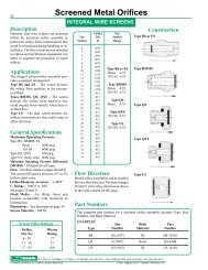
22DescriptionStainless steel wire screens are mountedwithin the precision orifice assembly toprotect the orifice from contaminationthat could be introduced during handlingor installation. The fine screensare not intended to replace normal filtrationequipment, but rather to augmentthe protection of small orifices.ApplicationsThe integral screen/orifice assembly providesa compact arrangement.Type BS and ES – The screen protectsthe orifice from particles in the pressurizedfluid.Types BMMS, QS, QXS – The screenprotects the orifice from particles thatcould migrate from outside, when thereis no fluid flow.Type US – The dual screen protects theorifices from particles that could enterin either direction.General SpecificationsMaximum Operating Pressure –Type BS, BMMS, ESBrass 2000 psig303 SS 4000 psigType QS, QXS 100 psigType US (body only) 4000 psigMaximum Differential Pressure – 100 psifor all types.Flow – See flow charts on pages 16 and 17.The screen will cause a decrease of 1 to 2%in flow chart value.<strong>Orifice</strong> Diameter Accuracy – ±.0003"C v Range – .00035 to .028See pages 16 and 17.Fluid Media – Air, Water, Gases andLiquids compatible with materials ofconstruction.Dimensions – See drawings on page 23.Screen Material – 304 SSScreen Filter Ratings<strong>Orifice</strong> MicronSize No. Rating4 - 10 1511 - 16 2517 - 35 100Screened <strong>Metal</strong> <strong>Orifice</strong>sINTEGRAL WIRE SCREENS<strong>Orifice</strong> SizeSize Dia. NumberNumber In. Range4 .00395 .00516 .00597 .00718 .00799 .009110 .010211 .011012 .012213 .013014 .014215 .015016 .01617 .01718 .01819 .01920 .02021 .02122 .02223 .02324 .02425 .02526 .02627 .02728 .02829 .02931 .03132 .03233 .03335 .035Part NumbersType BS or ESBrass 4-35303SS 4-35Type BMMSBrass 4-35303SS 4-35Type QSBrass 4-35Type QXS303SS 4-35Type US303SS 5-35Flow Direction<strong>Metal</strong> <strong>Orifice</strong> <strong>Assemblies</strong> can be used forflow in either direction. The data onpages 16 and 17 is for a flow direction asshown in the right column on this page.Type BS or ESType BMMSType QSType QXSType USConstructionThe complete part number for a screened orifice assembly includes Type, Size Number,and Body Material.EXAMPLESize Body PartType Number Material NumberBS 10 (.010") SS BS-10-SSQS 4 (.004") Brass QS-4-BRUS 16 (.016") SS US-16-SSP.O. BOX Q • TRUMBULL, CT 06611 • CT PHONE (203) 261-6711 • TOLL FREE PHONE (800) 533-3285 • FAX (203) 261-8331© O'KEEFE CONTROLS CO. • 2000 ALL RIGHTS RESERVED e-mail ca@okcc.com • website www.okcc.com
Type BS or ESScreenDimensionsNPT - Both EndsScreened <strong>Metal</strong> <strong>Orifice</strong>sINTEGRAL WIRE SCREENSSpecifications23HEX NIPPLEBody and <strong>Orifice</strong> – Brass or SSThreads – 1/8" or 1/4" NPTStandard <strong>Orifice</strong> Sizes – .004" to .035" Dia.LHEXType Dim. L HEX NPTBS .970" 7/16" 1/8"ES 1.38" 9/16" 1/4"Type BMMS.650"ScreenBLEED PLUGBody and <strong>Orifice</strong> – Brass or SSThread – 1/8" NPTStandard <strong>Orifice</strong> Sizes – .004" to .035" Dia.1/8" NPT7/16" HEXType QS10-32 StraightThread1/4"HEXScreenBLEED PLUGBody and <strong>Orifice</strong> – BrassThread – 10-32 UNFThread Seal – VitonStandard <strong>Orifice</strong> Sizes – .004" to .035" Dia.SealNPT.280"Type QXS.310"Seal1/4" HEX10-32 StraightThread7-1/2°ScreenBLEED PLUGBody and <strong>Orifice</strong> – 303 SSThread – 10-32 UNFThread Seal – VitonStandard <strong>Orifice</strong> Sizes – .004" to .035" Dia.Type US.230".2815"/.2825" Dia.DUAL SCREEN INSERTBody and <strong>Orifice</strong> – 303 SSScreen – 304 SSPress Fit Dimension –Press into bore .2795"/.2805" Dia.Standard <strong>Orifice</strong> Sizes – .005" to .035" Dia.Screen Both EndsP.O. BOX Q • TRUMBULL, CT 06611 • CT PHONE (203) 261-6711 • TOLL FREE PHONE (800) 533-3285 • FAX (203) 261-8331© O'KEEFE CONTROLS CO. • 2000 ALL RIGHTS RESERVED e-mail ca@okcc.com • website www.okcc.com
24DescriptionStainless steel wire screens are mountedwithin the precision orifice assembly toprotect the orifice from contaminationthat could be introduced during handlingor installation. The fine screensare not intended to replace normal filtrationequipment, but rather to augmentthe protection of small orifices.ApplicationsThe integral screen/orifice assembly providesa compact arrangement.All types on this pageThe screen is located upstream of theorifice and protects against particlescarried by the pressureized fluid.For protection against contamination inreverse flow situations add an externalscreen downstream of the orifice.General SpecificationsMaximum Operating Pressure –See page 25.Maximum Differential Pressure AcrossScreen – 100 psi.Flow – See flow charts on pages 16 and 17.The screen will cause a decrease of 1 to 2%in flow chart value.<strong>Orifice</strong> Diameter Accuracy – ±.0003"C v Range – .00035 to .028See pages 16 and 17.Fluid Media – Air, Water, Gases andLiquids compatible with materials ofconstruction.Dimensions – See drawings on page 25.Screen Material – 304 SSScreened <strong>Metal</strong> <strong>Orifice</strong>sINTEGRAL WIRE SCREENS<strong>Orifice</strong> SizeSize Dia. NumberNumber In. Range4 .00395 .00516 .00597 .00718 .00799 .009110 .010211 .011012 .012213 .013014 .014215 .015016 .01617 .01718 .01819 .01920 .02021 .02122 .02223 .02324 .02425 .02526 .02627 .02728 .02829 .02931 .03132 .03233 .03335 .0354-35All TypesBFSSDSFFOSFMOSGSIASODSFlow Direction<strong>Metal</strong> <strong>Orifice</strong> <strong>Assemblies</strong> can be used forflow in either direction. The data onpages 16 and 17 is for a flow direction asshown in the right column on this page.Type BFSSType DS, GSType FFOSType FMOSType IASType ODSConstructionScreen Filter Ratings<strong>Orifice</strong> MicronSize No. Rating4 - 10 1511 - 16 2517 - 35 100Part NumbersThe complete part number for a screened orifice assembly includes Type, Size Number,and Body Material.EXAMPLESize Body PartType Number Material NumberBFSS 10 (.010") Brass BFSS-10-BRGS 4 (.004") SS GS-4-SSIAS 16 (.016") Brass IAS-16-BRP.O. BOX Q • TRUMBULL, CT 06611 • CT PHONE (203) 261-6711 • TOLL FREE PHONE (800) 533-3285 • FAX (203) 261-8331© O'KEEFE CONTROLS CO. • 2000 ALL RIGHTS RESERVED e-mail ca@okcc.com • website www.okcc.com
Type BFSSDimensions#4 SAE 45° Flare7/16" • 20 Thd7/16" HEX1/8"NPTScreened <strong>Metal</strong> <strong>Orifice</strong>sINTEGRAL WIRE SCREENSSpecifications25SAE 45° FLARE ADAPTERBody and <strong>Orifice</strong> – BrassMaximum Operating Pressure – 2000 psigStandard <strong>Orifice</strong> Sizes – .004" to .035" Dia..15".50"1.04"Type DS, GSLNPTHEXNPTType Dim. L HEX NPTDS .88" 9/16" 1/8"GS 1.25" 3/4" 1/4"ADAPTERBody and <strong>Orifice</strong> – Brass or SSMinimum Operating PressureBrass Body – 2000 psigSS Body – 4000 psigStandard <strong>Orifice</strong> Sizes – .004" to .035" Dia.Type FFOSRound.312" Dia.COUPLERBody and <strong>Orifice</strong> – Brass or SSMaximum Operating Pressure – 100 psigStandard <strong>Orifice</strong> Sizes – .004" to .035" Dia.10-32Thread.510"10-32ThreadType FMOSRound.312" Dia.ADAPTERBody and <strong>Orifice</strong> – Brass or SSMaximum Operating Pressure – 100 psigSeal – VitonStandard <strong>Orifice</strong> Sizes – .004" to .035" Dia..570"10-32 Thread 10-32 ThreadType IAS.156".258"/.259" Dia.Press Fit Into .256"/.257" Dia.INSERTBody and <strong>Orifice</strong> – BrassMaximum Operating Pressure – 2000 psigStandard <strong>Orifice</strong> Sizes – .004" to .035" Dia.Type ODS9/16" - 18 UNF Thread5/8" HEX1/8" NPT.25" O-Ring.75"O-RING ADAPTERBody and <strong>Orifice</strong> – BrassMaximum Operating Pressure – 2000 psigSeal – VitonStandard <strong>Orifice</strong> Sizes – .004" to .035" Dia.P.O. BOX Q • TRUMBULL, CT 06611 • CT PHONE (203) 261-6711 • TOLL FREE PHONE (800) 533-3285 • FAX (203) 261-8331© O'KEEFE CONTROLS CO. • 2000 ALL RIGHTS RESERVED e-mail ca@okcc.com • website www.okcc.com
26DescriptionStainless steel wire screens are mountedwithin the precision orifice assembly toprotect the orifice from contaminationthat could be introduced during handlingor installation. The fine screensare not intended to replace normal filtrationequipment, but rather to augmentthe protection of small orifices.ApplicationsThe integral screen/orifice assemblyprovides a compact arrangement.Type BTFS and BWFS – The screen islocated upstream of the orifice andprotects against particles carried by thepressurized fluid.For protection against contamination inreverse flow situations add an externalscreen downstream of the orifice.Type JSS – The dual screen protects theorifice from particles that could enter ineither direction.General SpecificationsMaximum Operating Pressure –100 psigMaximum Differential PressureAcross Screen – 100 psiFlow – See flow charts on page 18.The screen will cause a decrease of1 to 2% in flow chart value.<strong>Orifice</strong> Diameter Accuracy – ±.0003"C v Range – .000030 to .013See page 18.Fluid Media – Air, Water, Gases andLiquids compatible with materials ofconstruction.Dimensions – See drawings on page 27.Screen Material – 304 SSScreen Filter Ratings<strong>Orifice</strong> MicronSize No. Rating3 - 26 1528 - 40 2544 - 64 100Screened Sapphire <strong>Orifice</strong>sINTEGRAL WIRE SCREENS<strong>Orifice</strong> SizeSize Dia. NumberNumber In. Range3 .00124 .00165 .00206 .00247 .00288 .00319 .003510 .003911 .004312 .004713 .005114 .005515 .005916 .006317 .006718 .007120 .007922 .008724 .009426 .010228 .011030 .011832 .012634 .013436 .014240 .015744 .017348 .018952 .020554 .021358 .022864 .0252Part Numbers3-64TypesBTFSBWFSJSSFlow DirectionThere is a preferred flow direction forsapphire orifice assemblies. See constructiondrawings at right.Type BTFSType BWFSType JSSConstructionThe complete part number for a screened orifice assembly includes Type, Size Number,and Body Material.EXAMPLESize Body PartType Number Material NumberBTFS 4 (.0016") Brass BTFS-4-BRBWFS 10 (.0039") SS BWFS-10-SSJSS 52 (.0205") Brass JSS-52-BRP.O. BOX Q • TRUMBULL, CT 06611 • CT PHONE (203) 261-6711 • TOLL FREE PHONE (800) 533-3285 • FAX (203) 261-8331© O'KEEFE CONTROLS CO. • 2000 ALL RIGHTS RESERVED e-mail ca@okcc.com • website www.okcc.com
Type BTFSScreened Sapphire <strong>Orifice</strong>s27INTEGRAL WIRE SCREENSDimensionsSpecifications1/8" NPT.875"7/16" HEXBarb for1/16" IDTubingADAPTERMaterialsBody – Brass or SS<strong>Orifice</strong> – Sapphire/Nylon SleeveMaximum Operating Pressure – 100 psig<strong>Orifice</strong> Sizes – .0012" to .0252" Dia.Connections – 1/8" NPT x 1/16" BarbType BWFS1/8" NPTBarb for 1/8"ID Tubing.940"9/16" HEXADAPTERMaterialsBody – Brass or SS<strong>Orifice</strong> – Sapphire/Nylon SleeveMaximum Operating Pressure – 100 psig<strong>Orifice</strong> Sizes – .0012" to .0252" Dia.Connections – 1/8" NPT x 1/8" BarbType JSS1/8" NPT - Both Ends7/16" HEX.970"DescriptionRestriction unions contain an easilyreplaceable orifice plate and are availablein carbon steel or stainless steel. Theassembly is used in liquid or gas pipingsystems to meter flow rate of the fluid. Theall metal assembly is capable of a widerange of pressure and temperaturevariables.ApplicationsRestriction orifice unions are used in settingflow rates of a wide variety of fluids.• Compressed Air• Water• Steam• Hydraulic Fluids• Gases• Chemicals• CoolantsFlow rates can be easily changed by insertingother replaceable metering plates.Restriction <strong>Orifice</strong> UnionsFLOW METERINGRestriction <strong>Orifice</strong> Unionhas SS plate with precisionmetering orifice.Restriction <strong>Orifice</strong> Unionsare threaded or socket weld.HEX NIPPLEMaterialsBody – Brass or SS<strong>Orifice</strong> – Sapphire/Nylon SleeveMaximum Operating Pressure – 100 psig<strong>Orifice</strong> Sizes – .0012" to .0252" Dia.Connections – 1/8" NPTP.O. BOX Q • TRUMBULL, CT 06611 • CT PHONE (203) 261-6711 • TOLL FREE PHONE (800) 533-3285 • FAX (203) 261-8331© O'KEEFE CONTROLS CO. • 2000 ALL RIGHTS RESERVED e-mail ca@okcc.com • website www.okcc.comSpecificationsMaterials<strong>Orifice</strong> Plate – 316 Stainless SteelUnion – A105 Carbon Steel or 316 SSSizes – 1/4", 3/8", 1/2", 3/4", 1", 1-1/4", 1-1/2", 2"Connections – NPT or Socket WeldPressure RatingCarbon Steel – 3000 psiStainless Steel – 3000 psiOrdering InformationIf orifice size is known provide• <strong>Orifice</strong> size, connection size, unionmaterial and connection typeIf orifice size is unknown provide• Connection size, union material andconnection type• All of the following data– fluid type– fluid supply pressure and temperature– pressure differential across orifice– required flow rate– pipe IDExtra plates – To order plates only, providethe same information as required above.
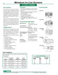
28DescriptionFine screens are used to protect orificesand other critical components from theoccasional particles that enter the fluidduring installation or otherwise. They arenot intended to replace normal filtrationequipment, but rather to augment the protectionof critical components in fluid controlsystems.Four sizes of screen particle retention areoffered; 10, 15, 25 and 100 microns. Thestainless steel wire screens do not introduceloose particles into the fluid stream.The screens are thoroughly cleaned toprevent inadvertent introduction of contaminants.TypeFFSMiniature In-Line ScreensRound.312" Dia.SS WIRE SCREENSApplicationsIn-line screens are suitable for use withliquids or gases compatible with the materialsof construction. The screens protectcritical components such as orificesfrom clogging or reducing flow rate.Applications for in-line screens includeprotection of:• Precision <strong>Orifice</strong>s• Pneumatic Transducers• Gas and Liquid Flow Instruments• Medical Devices• Filling and Purging Systems• Pneumatic Timers• Transmitters• Pneumatic Transmission Lines• Hydraulic <strong>Controls</strong>• Leak Test Equipment• Flow Measurement DevicesFeaturesThe in-line screen products are all metal;the screen material is made from finestainless steel wire.• Particle retention size as small as 10microns• Miniature fittings and screens• Clean assemblies• No loose fibers or particles• Long life screen material• Well defined flow characteristics• Compatible with standard 10-32 andNPT fittings10-32 Female ThreadBoth Ends.500"ScreenTypeFMSRound10-32 Male ThreadScreen.312" Dia..560"10-32 Female ThreadTypesDSOGSONPTNPTMaleNPTScreenFemaleNPTLHEXType L Hex NPTDSO .880" 9/16" 1/8"GSO 1.250" 3/4" 1/4"TypesSSASSBSSCDAWAType D W ASSA .211" .030" .10"SSB .254" .030" .15"SSC .312" .030" .22"TypesXSAXSBXSCXSDDWType D WXSA .211" .005"/.010"XSB .254" .005"/.010"XSC .312" .005"/.010"XSD .165" .005"/.010"P.O. BOX Q • TRUMBULL, CT 06611 • CT PHONE (203) 261-6711 • TOLL FREE PHONE (800) 533-3285 • FAX (203) 261-8331© O'KEEFE CONTROLS CO. • 2000 ALL RIGHTS RESERVED e-mail ca@okcc.com • website www.okcc.com
Miniature In-Line ScreensSS WIRE SCREENS29Part Numbers – Screen FittingsParticle Retention Body Material – Brass Body Material – SSType FFS Type FMS Type DSO Type GSO Type FFS Type FMS Type DSO Type GSOMicron <strong>Inc</strong>h 10-32 10-32 1/8" NPT 1/4" NPT 10-32 10-32 1/8" NPT 1/4" NPTThread Thread Thread Thread10 .0004 FFS-1-BR FMS-1-BR DSO-1-BR GSO-1-BR FFS-1-SS FMS-1-SS DSO-1-SS GSO-1-SS15 .0006 FFS-2-BR FMS-2-BR DSO-2-BR GSO-2-BR FFS-2-SS FMS-2-SS DSO-2-SS GSO-2-SS25 .0010 FFS-5-BR FMS-5-BR DSO-5-BR GSO-5-BR FFS-5-SS FMS-5-SS DSO-5-SS GSO-5-SS100 .0040 FFS-20-BR FMS-20-BR DSO-20-BR GSO-20-BR FFS-20-SS FMS-20-SS DSO-20-SS GSO-20-SSConfiguration10-32 10-32 1/8" NPT 1/4" NPT 10-32 10-32 1/8" NPT 1/4" NPTThread Thread Thread ThreadPart Numbers – ScreensBound or Plain TypesRecommended Screen/<strong>Orifice</strong> SizingChart Shows Maximum <strong>Orifice</strong> Diameter (inch) 1Particle RetentionMicron <strong>Inc</strong>h10 .000415 .0006Type Type Type TypeSSA SSB SSCXSA XSB XSC XSDSSA-1 SSB-1 SSC-1 —XSA-1 XSB-1 XSC-1 XSD-1SSA-2 SSB-2 SSC-2 —XSA-2 XSB-2 XSC-2 XSD-2Particle Retention Types FFS, FMS, DSO Type GSOGas Liquid Screen Gas Liquid ScreenMicron <strong>Inc</strong>h Flow Flow Cv Flow Flow CvMOD* MOD* MOD* MOD*10 .0004 .0064 * * .009 .011 * * .02815 .0006 .0105 * * .025 .018 * * .06825 .0010100 .0040SSA-5 SSB-5 SSC-5 —XSA-5 XSB-5 XSC-5 XSD-5SSA-20 SSB-20 SSC-20 —XSA-20 XSB-20 XSC-20 XSD-20Specifications• Body Materials – Brass or 303SS– Viton Seal on Type FMS• Screen Material – 304SS• Maximum Operating Pressure– Brass (NPT) – 2000 psig– 304SS (NPT) – 4000 psig– 10-32 Threads – 100 psig• Maximum Pressure DifferentialAcross Screen – 100 psig• Flow – See Cv in chart above• Fluids – Use with liquids or gases compatiblewith materials of construction• Dimensions – See drawings on page 2825 .0010 .0165 * * .055 .028 * * .180100 .0040 .0195 .0195 .090 .033 .033 .2501. When used with precision orifices, it is important that the screen not havea major influence on the flow through the orifice. The recommendedmaximum orifice when used with a screen will have less than 1% changein the orifice flow.* MOD – Maximum <strong>Orifice</strong> Diameter (<strong>Inc</strong>h)* * Do not use this screen for liquid flow.Ordering Information• Select the part number of the in-line screen fitting or bound screenfrom the charts above.• Indicate quantity required.P.O. BOX Q • TRUMBULL, CT 06611 • CT PHONE (203) 261-6711 • TOLL FREE PHONE (800) 533-3285 • FAX (203) 261-8331© O'KEEFE CONTROLS CO. • 2000 ALL RIGHTS RESERVED e-mail ca@okcc.com • website www.okcc.com
30BreathersSS WIRE SCREENSDescriptionFine screen breathers provide an air passageinto equipment, enclosures, and pneumaticcontrols while preventing the ingestionof solid particles. Miniature finescreen breathers are rated at 15, 25 or 100microns and are available in either brassor stainless steel fittings. Connection sizesare 10-32, 1/8" or 1/4" NPT.ApplicationsTypeQSBTypeBMB1/4" HEX.310"7/16" HEX10-32 Male ThreadSealScreen1/8" NPTThe fine screen breathers are used wherethere is a requirement to insure that onlyclean fluid enters into a component orsystem. Typical applications include:• Equipment enclosures• Vented control components• Small 3- or 4-way valves• Small 2-way vacuum valves• Air purge equipment• EMI or RFI shieldTypeEMB.650"9/16" HEXScreen1/4" NPTSpecifications• MaterialsBody – Brass or 303 SSScreen – 304 SSSeals – Viton (10-32 only)• Maximum Operating PressureBrass (NPT) – 2000 psig303 SS (NPT) – 4000 psig10-32 threads – 100 psig• Maximum Pressure DifferentialAcross Screen – 100 psi• Flow – See C v data in chart at right.• Fluids – Use with liquids or gases compatiblewith materials of construction.• Dimensions – See drawings this page.Ordering Information• Select the part number from the chartat right.• Indicate quantity and part number onorder..900"ScreenPart Numbers – BreathersFilter Rating Connection Part Number Flow(Microns) Size Brass Stainless Steel C v15 10-32 QSB-2-BR QSB-2-SS .02525 10-32 QSB-5-BR QSB-5-SS .055100 10-32 QSB-20-BR QSB-20-SS .09015 1/8" NPT BMB-2-BR BMB-2-SS .02525 1/8" NPT BMB-5-BR BMB-5-SS .055100 1/8" NPT BMB-20-BR BMB-20-SS .09015 1/4" NPT EMB-2-BR EMB-2-SS .06825 1/4" NPT EMB-5-BR EMB-5-SS .180100 1/4" NPT EMB-20-BR EMB-20-SS .250P.O. BOX Q • TRUMBULL, CT 06611 • CT PHONE (203) 261-6711 • TOLL FREE PHONE (800) 533-3285 • FAX (203) 261-8331© O'KEEFE CONTROLS CO. • 2000 ALL RIGHTS RESERVED e-mail ca@okcc.com • website www.okcc.com
Pressure SnubbersT 1H (Across Flats)TYPE Diameter-In. Size (NPT) Part Number Part Number31NPT CONNECTIONSOperationApplicationsPressure snubbers are used as in-line elementsto reduce rapid pressure fluctuationsin the following types of components:• Pressure GagesPressure Gage• Pressure Measuring InstrumentsSnubber• Air Piloted Valves• Hydraulic Piloted ValvesPressure snubber adapts to pressure gage, instrumentor control element with 1/8", 1/4" or 1/2" They can also be used to control the flowNPT connection.rate of fluid delivered to:<strong>Inc</strong>reasing•Without SnubberAir Cylinders• Hydraulic CylindersPressureInInstrument• Fluid ActuatorsWith SnubberSee illustrations for typical applications.ValveOpens ➝Time ➝Pressure Gage<strong>Inc</strong>reasingAfter a valve opens, the pressure in an instrumentValveor control device builds more slowly whenequipped with a pressure snubber.Pressure SnubberTo Use PointConstructionA pressure gage equipped with a snubber willrespond more slowly to pressure changes than agage without a snubber. This slowed responsedampens pressure spikes caused by valves andpumps.Pressure snubbers are in-line components whichreduce the rate of fluid flow to a gage, instrumentSnubberor control element and thus dampen shock andValveAir Pilotedfluctuating pressure effects.Valve orRegulatorMaterials• Brass• 303 Stainless Steel When valve opens the pressure in the pilot portMale Pipe Threadincreases slowly. In the case of an air loadedpressure regulator with a snubber, the output alsoincreases gradually rather than suddenly.<strong>Orifice</strong> ➝PressureFemale PipeInstrumentThreadSnubberPart NumbersTo Use PointValve<strong>Orifice</strong> Pipe Stainless Steel BrassDescriptionA simple in-line element called a pressuresnubber is used to reduce the rate of flowof fluids into pressure instruments and controls.A small orifice in an adapter fittingdampens shock and fluctuating pressureeffects by limiting the rate at which flowenters. The smaller the orifice, the greateris the dampening effect.The proper orifice size for any applicationdepends upon the size of the pressurizedchamber, the viscosity of the fluid and therequired response time of the system.<strong>Orifice</strong> sizes from .004" diameter to .020"diameter are available. In general, largeinstrument chambers require large floworifices. Viscous fluids require larger floworifices than low viscosity fluids. Gasesgenerally require small orifices.Specifications• Maximum Operating PressureBrass – 2000 psig303SS – 4000 psig• Flow Direction – Suitable for flow ineither direction• <strong>Orifice</strong> Diameter – Standard .004",.008", .015", .020". See chart at right.Special orifice sizes available; consultfactory.• Flow Rate –Air Flow to<strong>Orifice</strong> Atmos. @Diameter (in.) C V 25 psig inlet.004 .00035 .46 scfh.008 .0015 2.0 scfh.015 .0050 6.9 scfh.020 .0088 13.0 scfh• Fluid Media – Air, Water Gases andLiquids compatible with materials ofconstruction.DimensionsLType T 1(NPT) T 2(NPT) H-in. L-in.DP 1/8 1/8 9/16 .880GP 1/4 1/4 3/4 1.250HP 1/2 1/2 1-1/16 1.690T 2➝➝➝➝➝➝DP .004 1/8 DP-4-SS DP-4-BRDP .008 1/8 DP-8-SS DP-8-BRDP .015 1/8 DP-15-SS DP-15-BRGP .004 1/4 GP-4-SS GP-4-BRGP .008 1/4 GP-8-SS GP-8-BRGP .015 1/4 GP-15-SS GP-15-BRHP .004 1/2 HP-4-SS HP-4-BRHP .008 1/2 HP-8-SS HP-8-BRHP .015 1/2 HP-15-SS HP-15-BRHP .020 1/2 HP-20-SS HP-20-BR➝➝➝➝➝Pressure measuring instruments are protectedfrom surges when equipped with a snubber. Highfrequency pressure spikes are dampened by thesmall orifice in the pressure snubber.Ordering InformationTo order pressure snubbers, indicate quantityand obtain part number from the chart.P.O. BOX Q • TRUMBULL, CT 06611 • CT PHONE (203) 261-6711 • TOLL FREE PHONE (800) 533-3285 • FAX (203) 261-8331© O'KEEFE CONTROLS CO. • 2000 ALL RIGHTS RESERVED e-mail ca@okcc.com • website www.okcc.com
32<strong>Orifice</strong> KitsMETALDescriptionFor research and development of productsrequiring flow metering, it is convenientto have an accurate array of precision orifices.The kits described on this page providea wide range of orifice sizes and acorresponding wide range of metered flow.<strong>Metal</strong> orifice and sapphire orifice kits usecompartmented plastic boxes for storageof the precision restrictors.The Micro-<strong>Orifice</strong>s ® provided in kits includeprotective screens to protect againstcontamination during handling and installation.Kit contains anassortment of orifice sizes of one type.<strong>Metal</strong> <strong>Orifice</strong>sKit Reference <strong>Orifice</strong>Type Part Number Catalog Page Body Material Quantity DiametersBBTBWDMNQXTWKB-58-BR 8 Brass 58 (1 each) .004" to .125"KB-174-BR 8 Brass 174 (3 each) .004" to .125"KB-56-SS 8 303SS 56 (1 each) .006" to .125"KB-168-SS 8 303SS 168 (3 each) .006" to .125"KBT-30-BR 6 Brass 30 (1 each) .004" to .035"KBT-90-BR 6 Brass 90 (3 each) .004" to .035"KBW-42-BR 6 Brass 42 (1 each) .004" to .063"KBW-126-BR 6 Brass 126 (3 each) .004" to .063"KBW-40-SS 6 303SS 40 (1 each) .006" to .063"KBW-120-SS 6 303SS 120 (3 each) .006" to .063"KD-58-BR 8 Brass 58 (1 each) .004" to .125"KD-174-BR 8 Brass 174 (3 each) .004" to .125"KD-56-SS 8 303SS 56 (1 each) .006" to .125"KD-168-SS 8 303SS 168 (3 each) .006" to .125"KM-30-BR 6 Brass 30 (1 each) .004" to .035"KM-90-BR 6 Brass 90 (3 each) .004" to .035"KN-42-BR 6 Brass 42 (1 each) .004" to .063"KN-126-BR 6 Brass 126 (3 each) .004" to .063"KQX-30-BR 6 Brass 30 (1 each) .004" to .035"KQX-90-BR 6 Brass 90 (3 each) .004" to .035"KQX-28-SS 6 303SS 28 (1 each) .006" to .035"KQX-84-SS 6 303SS 84 (3 each) .006" to .035"KT-30-BR 6 Brass 30 (1 each) .004" to .035"KT-90-BR 6 Brass 90 (3 each) .004" to .035"KT-28-SS 6 303SS 28 (1 each) .006" to .035"KT-84-SS 6 303SS 84 (3 each) .006" to .035"KW-42-BR 6 Brass 42 (1 each) .004" to .063"KW-126-BR 6 Brass 126 (3 each) .004" to .063"KW-40-SS 6 303SS 40 (1 each) .006" to .063"KW-120-SS 6 303SS 120 (3 each) .006" to .063"® Registered Trademark of <strong>O'Keefe</strong> <strong>Controls</strong> Co.P.O. BOX Q • TRUMBULL, CT 06611 • CT PHONE (203) 261-6711 • TOLL FREE PHONE (800) 533-3285 • FAX (203) 261-8331© O'KEEFE CONTROLS CO. • 2000 ALL RIGHTS RESERVED e-mail ca@okcc.com • website www.okcc.com
<strong>Orifice</strong> KitsSAPPHIRE AND MICRO33Sapphire <strong>Orifice</strong>sKit Reference <strong>Orifice</strong>Type Part Number Catalog Page Body Material Quantity DiametersAFKA-96-NY 4 Nylon 96 (3 each) .0012" to .0252"KF-96-NY 4 Nylon 96 (3 each) .0012" to .0252"JLPSKJ-96-BR 4 Brass 96 (3 each) .0012" to .0252"KJ-96-SS 4 303SS 96 (3 each) .0012" to .0252"KL-96-BR 4 Brass 96 (3 each) .0012" to .0252"KL-96-BR-EN 4 Brass (Plated) 96 (3 each) .0012" to .0252"KP-96-BR 4 Brass 96 (3 each) .0012" to .0252"KS-96-BR 4 Brass 96 (3 each) .0012" to .0252"KS-96-BR-EN 4 Brass (Plated) 96 (3 each) .0012" to .0252"BLPMLPQXLPMicro-<strong>Orifice</strong>s ® KBLPS-9-BR 19 Brass 9 (1 each) .0003" to .0035"KBLPS-11-SS 19 303SS 11 (1 each) .0003" to .005"KMLPS-9-BR 19 Brass 9 (1 each) .0003" to .0035"KQXSLP-9-BR 19 Brass 9 (1 each) .0003" to .0035"KQXSLP-11-SS 19 303SS 11 (1 each) .0003" to .005"Custom <strong>Orifice</strong> <strong>Assemblies</strong>Special orifice assemblies can be providedwhere quantity requirements aresufficiently large. Shown to the rightare a few of the custom assemblies producedusing sapphire or metal orifices.Oftentimes sapphire or metal orificescan be press fit into standard threadedor tube fittings. In other cases specialfittings incorporating metal orifices aremachined to order. Integral screens canalso be included in special configurations.Some of the custom precision orificeassemblies which have previouslybeen manufactured are:• Modified standard pipe, tube orprocess fittings with orifice inserts.• Custom machined orifice assemblies.• Custom orifices with integralscreen.• <strong>Orifice</strong> manifolds for flow selection.® Registered Trademark of <strong>O'Keefe</strong> <strong>Controls</strong> Co.P.O. BOX Q • TRUMBULL, CT 06611 • CT PHONE (203) 261-6711 • TOLL FREE PHONE (800) 533-3285 • FAX (203) 261-8331© O'KEEFE CONTROLS CO. • 2000 ALL RIGHTS RESERVED e-mail ca@okcc.com • website www.okcc.com
34Fundamentals of Flow MeasurementGAS FLOW MEASUREMENTThe Standard Cubic FootVolumetric FlowThe flow of gases is traditionally measuredin volumetric units such as cubic feet, litersor cubic centimeters. However, sincegases are compressible fluids, the totalmass contained in a given volume varieswith both the temperature and pressure ofthe gas. To provide a meaningful referencefor volumetric flow measurements, a"standard" set of conditions are defined fortemperature and pressure of the gas.Unfortunately, the definition of standardconditions varies slightly in technicaldisciplines and industry groups. Standardtemperature ranges from 32 to 70ºF (0 to20ºC). Standard pressure is generallyaverage atmospheric pressure at sea-level,14.7 psia.Standard ConditionsFor the data presented in the charts onpages 16-18, standard conditions are 70°Fand 14.7 psia. For data points measuredby <strong>O'Keefe</strong> <strong>Controls</strong> Co., the same standardconditions are used.A mass flowmeter measures flow accurately andrelatively independent of barometric pressure.The unit shown above is used to obtain the data forcalibrated orifices.Factors to ConsiderIn comparing volumetric flow measurementstaken at different locations andwith different measuring equipment,the following factors should be considered:• Definition of Standard ConditionsBetween 32ºF and 70ºF, the standardconditions can vary up to 8%.• Temperature of the GasA 10ºF deviation causes about 1%error in a rotameter reading. Moreor less deviation occurs in other typeflow measuring instruments. The deviationsare predictable and the flowmeasurement is correctable.• Barometric PressureNormal atmospheric pressure variationsof ±1/2" Hg. can cause morethan 1% error in rotameters. Altitudeis also an important factor, since thebarometric pressure decreases rapidlywith increasing altitude. At anelevation of 2,000 ft. above sea level,rotameter scale readings are in errorby 3-1/2%. These errors can be correctedquite easily with predictablecorrection factors, and accurateknowledge of barometric pressure.What To Do To ImproveMeasurement AccuracyIn many applications, errors of ±10% inflow rate are unimportant. In this case,corrections for 1) standard conditions, 2)barometric pressure and 3) temperatureare not required.1. Definition of Standard ConditionsThe data on pages 16-18 is for standardconditions of 70ºF and 14.7 psia. To reconciledata taken from volumetric instrumentswhich are referenced to differentstandard conditions, use the followingformula:Q s= Q mx P m x T SP ST mQ m= measured volumetric flow (SCFH)or (SLPM).Q s= volumetric flow corrected to 70ºFand 14.7 psia.P m= standard barometric pressure referencedby manufacturer (psia). This is generally14.7 psia.P s= standard barometric pressure = 14.7 psia.T m= Standard absolute temperature referencedby manufacturer (ºRankine).T s= standard absolute temperature = 530ºR.For Example:A mass flowmeter manufacturer uses thefollowing standard conditions:14.7 psia, 32°F (492°R)To convert to standard conditions of 70ºF(530ºR) and 14.7 psia, apply the following:Q S= Q mx P mx T S= Q mx 14.7 x 53014.7 492P S= 1.077 Q mT mThe volumetric flow Q Sis larger than Q mby 7.7%. Consult the manufacturer of yourflow measuring equipment to insure thatyou know exactly the standard conditionswhich apply to your equipment.2. Temperature EffectsConsult your instrument manufacturer fortemperature correction factors. There aretwo temperature considerations.1. Effect of ambient temperature on theflow measuring instrument2. Effect of gas temperature on the flowmeasuring instrument3. Barometric Pressure EffectsConsult your instrument manufacturer forpressure correction factors. There are twopressure considerations.1. Effect of barometric pressure on theflow measuring instrument2. Effect of gas pressure on the flow measuringinstrumentTable of AverageBarometric PressureAltitude Barometer AtmosphericAbove Sea Level Reading PressureFeet <strong>Inc</strong>hes Mercury PSIA0 29.92 14.696500 29.38 14.431000 28.86 14.161500 28.33 13.912000 27.82 13.662500 27.32 13.413000 26.82 13.173500 26.33 12.934000 25.84 12.694500 25.37 12.465000 24.90 12.235500 23.99 11.787000 23.10 11.348000 22.23 10.91P.O. BOX Q • TRUMBULL, CT 06611 • CT PHONE (203) 261-6711 • TOLL FREE PHONE (800) 533-3285 • FAX (203) 261-8331© O'KEEFE CONTROLS CO. • 2000 ALL RIGHTS RESERVED e-mail ca@okcc.com • website www.okcc.com
Extending <strong>Orifice</strong> Flow DataEXTRAPOLATION351. Specific GravityOther GasesTo convert air flow from chart to anothergas flow.Flow (gas) = Flow (air) / S.G. (gas)EXAMPLE:To obtain flow rate for helium when airflow is 5 SCFHFlow (Helium) = Flow (air) / .138= 5 / .371 = 13.48 SCFHS.G. = specific gravity of gas relative to airS.G. = .138 for HeliumSpecific ChartGas Gravity 1 Multiplier 2Air 1.0 1.0Argon 1.379 .852Carbon Dioxide 1.53 .809Helium .138 2.68Hydrogen .0696 3.79Methane .554 1.34Natural Gas .61 1.28Nitrogen .972 1.01Oxygen 1.1053 .95Propane 1.56 .80Note 1 Specific gravity relative to air @ 70°F, 14.7 psiaNote 2 To obtain the flow of gases other than air,multiply the air flow values on the charts on pages16, 17 and 18 by the chart multiplier.2. Pressure – Air FlowHigh Pressure ExtrapolationTo calculate flow rates at pressures higherthan those on the charts, use the followingformula.Q HP = Q 80 x P HP + 14.794.7Q HP = Flow at elevated pressure(above 80 psig.).Q 80 = Chart flow reading at 80 psig.P HP = Elevated pressure in psig.EXAMPLE:To calculate the flow for the No. 16 metalorifice at 150 psig supply pressure.Q HP = 17.99 x 150 + 14.7 = 31.15 SCFH94.7(from chart)➞Low Pressure ExtrapolationTo calculate flow rates at pressures lowerthan those on the charts, use the followingformula.Q LP = Q 5P LP2 + 29.4 P LP13.12Q LP = Flow at the low pressure(below 5 psig.)Q 5 = Chart flow reading at 5 psig.P LP = Low pressure in psig.EXAMPLE:To calculate the flow at a supply pressureof 0.5 psig. for the No. 16 metal orifice.Q LP = 3.260.5 2 + 29.4 (.5) = 0.96 SCFH13.12(from chart)➞3. Temperature EffectsAir FlowThe flow of gases through an orifice variesinversely as the absolute temperature.As the gas temperature rises and the gasdensity decreases, the mass flow rate alsodecreases.To extend the chart data on pages 16, 17for air flow, use the following formula.QT T= Q S ST TWhere:T S = standard absolute temperature °R(°R = 460 + °F).T T = non standard absolute temperature °R.Q S = flow from chart at 70°F = 530°R.Q T = flow at a different temperature.EXAMPLE:At 70°F and an inlet pressure of 25 psigthe No. 60 (.060" dia.) orifice has a flowrate of 55 SLPM (see page 17). Undersimilar conditions, the air flow rate at300°F isQ T= 52.8530760= 44.09 SLPM4. Other <strong>Orifice</strong> SizesAir FlowTo calculate the required diameter of anorifice that is not included in the charts onpages 16-17 use the following formula.The equations are based on data taken forthe size no. 60 (.060" dia.) orifice.d L = .060Q Lin. dia.Q 60Where:d L = diameter of the unknown orifice.Q L = flow through the unknown orifice.Q 60 = flow from chart on pages 16-17.EXAMPLE: (data from page 17)At supply pressure of 50 psig and outlet atstandard conditions,Q 60 = 87.4 SLPM (from chart)Let:Q L = 600 SLPM @ 50 psigd L = .06060087.4= .157 in. dia.Water FlowUsing the C V method for liquid flow, andusing measured C V data we can derive thefollowing formula to calculate requiredorifice sizes.d L =1 Q L22.5 ∆PWhere:d L = diameter of unknown orifice (in.)Q L = required flow (gpm)EXAMPLE:Flow rate required =.5 GPM @ ∆P = 1.0 psid L =Also, to obtain the C VC VL =1 .5= .149" dia.22.5 1Q L .5=∆P 1= .5C VLis the C Vfor the orifice withdiameter = d L .P.O. BOX Q • TRUMBULL, CT 06611 • CT PHONE (203) 261-6711 • TOLL FREE PHONE (800) 533-3285 • FAX (203) 261-8331© O'KEEFE CONTROLS CO. • 2000 ALL RIGHTS RESERVED e-mail ca@okcc.com • website www.okcc.com
36Technical ConsiderationsMISCELLANEOUSConversion FactorsA. Gas FlowSCFH - standard cu. ft. per hourSLPM - standard liters per minuteSCCM - standard cu. cm. per minuteSCFH x .472 = SLPMSCFH x 472 = SCCMSLPM x 1000 = SCCMEXAMPLE:5 SCFH x .472 = 2.36 SLPMB. Liquid FlowGPM - gallons per minuteLPM - liters per minuteCCM - cubic centimeters per minuteCFH - cubic feet per hourCFM - cubic feet per minuteGPM x 3.785 = LPMGPM x 3785 = CCMGPM x .1337 = CFMGPM x 8.021 = CFHCCM x .001 = LPMEXAMPLE:25 GPM x 3.785 = 94.625 LPMC. Pressure – Gases or LiquidsPSIG - pounds per sq. in. gageKg/CM 2 - kilograms per sq. cmKPA - kilo pascalsBar - unit of pressure equal to 1 atmos.In-H 2O - pressure produced by 1" H 2OPSIG x .0703 = Kg/CM 2PSIG x 6.895 = KPAPSIG x .0689 = BarsPSIG x 27.68 = In. H 2OEXAMPLE:25 psig x 6.895 = 172.37 KPALiquid Flow C v MethodA. WaterThe C v method of rating flow capacity ofvarious devices employs empirical databased on water flow. The basic formula forwater flow isQ = C v ∆PQ = flow in GPM∆P = pressure differential in psiC v = flow factorFor a flow of 1 gpm at ∆P = 1, the C v = 1To obtain the water flow rate through precisionorifices use the above equation and obtainthe C v value from the charts on pages16, 17, 18.EXAMPLE:Size Number 100 (.100" dia.) has a C v = .23For a 25 psig pressure differential:Q = C v ∆ P = .23 25 = 1.15 GPMB. Other LiquidsFor liquids other than water, the equationbecomes:∆ PQ = Cv S.GWhere:S.G. = Specific gravity of the liquid(The specific gravity of water is 1.0)To obtain the flow rate of an oil with S.G. =.85, use the above equation and obtain theC v value from the charts on pages 16, 17, 18.EXAMPLE: Size number 100 (.100" dia.)has a C v = .23For a 25 psig pressure differential:Q = C v∆ P = .23S.G.25 = 1.25 GPM.85Specific Gravity of VariousLiquids Relative to Water @ 60ºFAlcohol, Ethyl .79Gasoline .75Glycerine 1.26Kerosene .80Diesel Oil .85Lube Oil .90Turpentine .87Water 1.00Test ProceduresA. Rotameters - Gas FlowRotameters for measurement of air or othergas flows must be used for the conditionsfor which they are calibrated. Typically theyare calibrated for the following:• Air Flow• Outlet Conditions - 14.7 psig @ 70ºFRotameters can be calibrated for other gasflows or other outlet pressure conditions.Manufacturers also provide graphs or tablesfor correction of measured data when conditionsvary from the calibration conditions.When using rotameters calibrated for standardoutlet conditions use the test proceduresshown below.Positive Supply PressureAirInSupplyPressureVacuum SourceAtmosphericInletPressureRotameter<strong>Orifice</strong><strong>Orifice</strong>RotameterExhaustToAtmosphereVacuumGageToVacuumSourceB. Mass Flowmeters - Gas FlowMass flowmeters are generally insensitiveto gas pressure or barometric pressure conditions.Consequently their location in thetest circuit is not critical. Consult your instrumentmanufacturer for recommendedtest procedures.C. Instrument Accuracy - Gas FlowThe three variables to be measured in gasflow applications are:• Pressure• Temperature• Flow RateThe accuracy of the flow measurement of agas through an orifice is limited by the combinedaccuracy of the instruments used inthe measurement. Expected accuracy of agas flow measurement is generally in therange of 1 to 20%. 1% accuracy can only beachieved with high quality instruments.P.O. BOX Q • TRUMBULL, CT 06611 • CT PHONE (203) 261-6711 • TOLL FREE PHONE (800) 533-3285 • FAX (203) 261-8331© O'KEEFE CONTROLS CO. • 2000 ALL RIGHTS RESERVED e-mail ca@okcc.com • website www.okcc.com
Calibrated <strong>Orifice</strong>sWATER OR AIR FLOW37Air FlowFor flow standards or other critical uses,<strong>O'Keefe</strong> <strong>Controls</strong> Co. can provide measuredair flow data for any of the standard precisionorifice products. This optional serviceis available at a nominal charge and can beprovided for pressure or vacuum flow conditionsin the standard ranges listed below.A calibration sheet with measured data isprovided for each orifice (see sample below).Data is obtained using a digital mass flowmetertraceable to the National Institute ofStandards Technology (NIST). Standardconditions are 70ºF and 14.7 psia(See photo page 34).Air flow can be measured for any of thefollowing conditions:Pressure 0-5, 0-10, 0-20, 0-50, 0-100 psigVacuum 0-30" HgFlow 0-.002, 0-.01, 0-.02, 0-.05,0-.1, 0-.2, 0-.5, 0-1, 0-2, 0-5,0-10, 0-20, 0-50, 0-200 SLPMFlow 0-.004, 0-.02, 0-.04, 0-.10,0-.2, 0-.4, 0-1, 0-2, 0-4, 0-10,0-20, 0-40, 0-100, 0-400 SCFHC v MeasurementWater at a constant height equivalent to 1 psig isused to determine the amount of water that passesthrough a test orifice in a measured time period.The C v is calculated from the measured data.Water FlowCalibration of standard orifices using waterflow is accomplished by measuring thequantity of water flowing through an orificein a given time period at a specific inletpressure.The calibration procedure determines thewater flow rate through the orifice and thecorresponding C v of the orifice is calculated.The C v can then be used to predictthe water flow rate at varying differentialpressure conditions using the equation:Q = C v∆PFor liquids other than water flow rate canalso be predicted using the C v method. Seepage 36 for details on liquid flow - C vmethod.A calibration sheet with measured data isprovided for each orifice. The calculated C vis the average value computed from fiveseparate tests (see sample below).P.O. BOX Q • TRUMBULL, CT 06611 • CT PHONE (203) 261-6711 • TOLL FREE PHONE (800) 533-3285 • FAX (203) 261-8331© O'KEEFE CONTROLS CO. • 2000 ALL RIGHTS RESERVED e-mail ca@okcc.com • website www.okcc.com
38The Basic ConceptA greatly misunderstood and misappliednotion is that of “choked flow”, also referredto as “critical flow”.In gas flow through an orifice there is an occasionwhere the gas velocity reaches sonicconditions. This occurs for air flow when theabsolute pressure ratio is .528, i.e. when thedownstream absolute pressure (P 2) is 52.8%of the upstream absolute pressure (P 1).P 1P 2Sonic velocity occurs for air flow whenP 2 /P 1 ≤ .528.AirVelocity➔The air flow velocity is limited once the absolutepressure ratio is ≤ .528.For air flow through an orifice with aninlet air temperature of 68 o F the choked(sonic) velocity is 1129 ft/sec.The Misconception!Once sonic velocity is achieved in orifice airflow (P 2/P 1= .528), it is easy to "assume" thatthe mass flow rate is constant for all pressureratios less than .528; i.e. P 2/P 1≤ .528. Forexample, when P 2is 14.7 psia and P 1is 27.84psia, sonic velocity occurs through the orifice.As P 1further increases there is no furtherincrease in the velocity of the air flowingthrough the orifice.P 1 = 27.84 psia= 13.14 psigSonic VelocityConditions for the onset of sonic velocity in orifice air flow.Consider all the Factors!The mass flow rate through an orifice is a functionof three basic parameters.Q (flow) is a function of• Velocity• Density• <strong>Orifice</strong> Area1129 ft/sec @68°FAir velocity isconstant inthis region01 .528➔ 0P 2 /P 1 – Absolute Pressure RatioSonic VelocityThrough <strong>Orifice</strong>P 2 = 14.7 psia= 0 psigChoked Flow of GasesWhen the air velocity reaches sonic velocity(P 2/P 1≤ .528) further increases in P 1(upstreampressure) do not cause any further increase inthe air velocity through the orifice. Consequentlyit is wrongly concluded that the massflow rate also does not increase.As the air pressure (P 1) increases, the densityof the air also increases; and since the massflow rate is also a function of density, the massflow rate increases linearly with pressure (P 1).MassFlow Rate➔Sonic VelocityAir Velocity01 .528Mass FlowRateP 2 = 14.7 psia= 0 psigEven though the air velocity through the orifice is limitedto the speed of sound, the mass flow rate continues toincrease as the absolute pressure (P 1) increases.What is Choked?The parameter that becomes “choked” or“limited” is the velocity of the air. It is moreaccurate to use the term “choked velocity”rather than “choked flow” when the absolutepressure ratio of air through an orifice is≤ .528.Vacuum ConditionsP 1 = 14.7 psia= 0 psigStandardAtmosphericConditionsAir at atmospheric pressure enters the orifice and flowsto a downstream vacuum pump.In the case of vacuum conditions on the outletof an orifice and where the inlet is at ambientatmospheric pressure, both the air velocityand the mass flow rate become choked(limited) when sonic velocity is achievedthrough the orifice.➔MassFlow RateTUTORIALFor atmospheric inlet pressure and downstream vacuum,both the air velocity and mass flow rate are limited.The reason for the mass flow rate limitation isthe fixed inlet density combined with the fixedvelocity. The flow charts on pages 16-18 showthe choked mass flow effect for vacuum conditions.At vacuum levels between 15-30” Hgthe mass flow rate is fixed.Choked Flow for PositivePressure ConditionsAs in the case of the above vacuum conditionsthere are certain situations in which chokedflow does occur for positive (above atmospheric)pressure. By maintaining a fixed inletpressure to the orifice and allowing theoutlet pressure (back pressure) to vary, thereis a range of outlet pressures over which themass flow rate is fixed.For example (see chart below).• With an inlet pressure of 80 psig, the massflow rate is choked (limited) for all outletpressures less than 35.30 psig (includingvacuum conditions).• The actual flow rate is constant for theoutlet pressure range of 35.30 psig to aslow as a complete vacuum. The flow ratecan be obtained from the charts on pages16-18; e.g. for an orifice of .010" diameterand with 80 psig inlet pressure, thechoked flow rate is 8.4 scfh (page 16). Thisflow rate will be constant for all outletpressure conditions between 35.30 psigand full vacuum.P.O. BOX Q • TRUMBULL, CT 06611 • CT PHONE (203) 261-6711 • TOLL FREE PHONE (800) 533-3285 • FAX (203) 261-8331© O'KEEFE CONTROLS CO. • 2000 ALL RIGHTS RESERVED e-mail ca@okcc.com • website www.okcc.com➔0➔ 0P 2 /P 1 – Absolute Pressure RatioSonic Velocity1129 ft/sec @68°FP Choked Flow1 = 14.7 psiaChoked Velocity01 .528➔ 0P 2 /P 1 – Absolute Pressure RatioAirVelocityP 2 < P 1Vacuum➔AirVelocitySonic Velocity Conditions – Air FlowInlet PressureOutlet PressureFor Sonic VelocityGage Absolute Absolute GagePressure Pressure Pressure Pressurepsig psia psia psig100 114.7 ≤ 60.56 ≤ 45.8690 104.7 ≤ 55.28 ≤ 40.5880 94.7 ≤ 50.00 ≤ 35.3070 84.7 ≤ 44.72 ≤ 30.0260 74.7 ≤ 39.44 ≤ 24.7450 64.7 ≤ 34.16 ≤ 19.4640 54.7 ≤ 28.88 ≤ 14.1830 44.7 ≤ 23.60 ≤ 8.9020 34.7 ≤ 18.32 ≤ 3.6215 29.7 ≤ 15.68 ≤ .9814.7 29.4 ≤ 15.52 ≤ .8210 24.7 ≤ 13.08 ≤ -1.625 19.7 ≤ 10.40 ≤ -4.301 15.7 ≤ 8.29 ≤ -6.470 14.7 ≤ 7.76 ≤ -6.94Temperature 68°F
DescriptionThe fixed flow rate orifices contain adeformable opening which decreases insize as the pressure differential increases.The design of the unit compensatesfor pressure differential increaseby reducing the area of the orifice resultingin constant flow over the differentialpressure range 15-150 psig.SpecificationsMaximum Pressure 150 psigConstant Flow Pressure Range 15 - 150 psigTemperature Range 32 to 160 o FAccuracy + 10%Materials Body - Brass • Diaphragm - Buna-NApplicationsWater Flow Rate ControlHeating and Cooling SystemsWater SprayFilm Process and RinseWater ConservationFlow Rate LimitationOrdering Information• Select the flow rate• Select the pipe size• Obtain part number from charts at rightDimensionsSeries 2305A. B. C.Pipe Size - Overall HeightNPT Length1/4" 2" 1-1/6"3/8" 1-3/4" 1-1/16"1/2" 2-7/32" 1-1/4"3/4" 2-9/16" 1-17/32"Series 2307A. B. C.Pipe Size - Overall HeightNPT Length3/4" 3-19/32" 2-7/8"1" 3-19/32" 2-7/8"1-1/4" 6-3/16" 5-1/4"1-1/2" 8-7/8" 7-3/8"Fixed Flow Rate <strong>Orifice</strong>s230523073/4", 1" NPT23071- 1 /4", 1- 1 /2" NPTWATER FLOWPart Numbers - Series 2305FLOW RATEPIPE SIZEGPM-H 2O 1/4" NPT 3/8" NPT 1/2" NPT 3/4" NPT0.20 2305-0011-1/40.25 2305-1011-1/40.30 2305-0031-1/4 2305-0031-3/80.40 2305-0041-1/4 2305-0041-3/80.50 2305-1021-1/4 2305-1021-3/8 2305-1021-1/20.60 2305-0061-1/4 2305-0061-3/8 2305-0061-1/20.75 2305-1031-1/4 2305-1031-3/8 2305-1031-1/21.00 2305-1041-1/4 2305-1041-3/8 2305-1041-1/2 2305-1041-3/41.25 2305-1051-1/4 2305-1051-3/8 2305-1051-1/2 2305-1051-3/41.50 2305-1061-1/4 2305-1061-3/8 2305-1061-1/2 2305-1061-3/41.75 2305-1071-1/4 2305-1071-3/8 2305-1071-1/2 2305-1071-3/42.00 2305-1081-1/4 2305-1081-3/8 2305-1081-1/2 2305-1081-3/42.50 2305-1091-1/2 2305-1091-3/43.00 2305-1101-1/2 2305-1101-3/43.50 2305-1111-1/2 2305-1111-3/44.0 2305-1121-1/2 2305-1121-3/44.5 2305-1131-3/45 2305-1141-3/46 2305-1151-3/47 2305-1161-3/48 2305-1171-3/49 2305-1181-3/410 2305-1191-3/4Part Numbers - Series 23070.2 to 10 GPM8 to 100 GPMFLOW RATEPIPE SIZEGPM-H 2O 3/4" NPT 1" NPT 1-1/4" NPT 1-1/2" NPT8 2307-1171-3/4 2307-1171-19 2307-1181-3/4 2307-1181-110 2307-1191-3/4 2307-1191-111 2307-1201-3/4 2307-1201-112 2307-1211-3/4 2307-1211-113 2307-1221-3/4 2307-1221-114 2307-1231-3/4 2307-1231-115 2307-1241-3/4 2307-1241-116 2307-1251-3/4 2307-1251-117 2307-1261-3/4 2307-1261-118 2307-1271-3/4 2307-1271-1 2307-1271-1-1/419 2307-1281-1 2307-1281-1-1/420 2307-1291-1 2307-1291-1-1/421 2307-1301-1 2307-1301-1-1/422 2307-1311-1 2307-1311-1-1/424 2307-1321-1-1/426 2307-1331-1-1/428 2307-1341-1-1/430 2307-1351-1-1/432 2307-1361-1-1/434 2307-1371-1-1/436 2307-1381-1-1/438 2307-1391-1-1/440 2307-1401-1-1/442 2307-1411-1-1/444 2307-1421-1-1/446 2307-1431-1-1/448 2307-1441-1-1/450 2307-1451-1-1/255 2307-1461-1-1/260 2307-1471-1-1/265 2307-1481-1-1/270 2307-1491-1-1/275 2307-1501-1-1/280 2307-1511-1-1/285 2307-1521-1-1/290 2307-1531-1-1/295 2307-1541-1-1/2100 2307-1551-1-1/239P.O. BOX Q • TRUMBULL, CT 06611 • CT PHONE (203) 261-6711 • TOLL FREE PHONE (800) 533-3285 • FAX (203) 261-8331© O'KEEFE CONTROLS CO. • 2000 ALL RIGHTS RESERVED e-mail ca@okcc.com • website www.okcc.com
40Water Flow TotalizersREMOTE READOUTDescriptionThe remote water totalizer system consists of astandard water totalizing meter that is adapted with acontact switch which provides one pulse per gallon;and a remote self powered electronic LCD eight digitdisplay. No external electric power is required.Battery life for the remote register is 10 years.The meter can be installed in a location not normallyaccessible and the remote readout conveniently locatedfor easy observation. The readout can be up to 1000feet from the flowmeter.SpecificationsMaximum Pressure – 150 psigFlow Accuracy + 2% of readingReadout – Self Powered • 10 year battery life8 digit • 3/8" heightMaximum Temperature Cold Water Meter • 125 O FHot Water Meter • 250 O FMeter Body – BronzeCable Length – 6 ft. standard– can be extended to 1000 ft.2-1/4"Remote ReadoutOKC-13195"1-3/4"Flow Totalizerwith CouplingsColdWaterMeterHotWaterMeterCatalog NumbersRemote ReadoutSelf PoweredFlow Rate - GPMPart Number Pipe Size (NPT) Min. Max. ReadoutOKC-1317-2 3/4" .25 20 8 digit/gallonsOKC-1317-3 1" .75 50 8 digit/gallonsOKC-1317-4 1-1/2" 1.5 100 8 digit/gallonsOKC-1317-5 2" 2.0 130 8 digit/gallonsOKC-1318-2 3/4" 2 20 8 digit/gallonsOKC-1318-3 1" 4 50 8 digit/gallonsOKC-1318-4 1-1/2" 7 100 8 digit/gallonsOKC-1318-5 2" 9 130 8 digit/gallonsABDimensions3/4" 1" 1-1/2" 2"Meter Only7-1/2" 10-3/4" 12-5/8" 10-5/8"With Couplings (MNPT)12-5/8" 16-1/8" 18-1/2" 16-7/8"The remote readout is included with eachtotalizer. It is also available separately.Remote Readout Only• Catalog Number OKC-1319• Operates on remote contact closure• Self powered internal lithium battery -10 year typical life• 8 digits – 3/8" height• Heavy duty enclosurePressure Drop –PSITypical Pressure Drop Curve3/4" 2.5 5 7.5 10 12.5 15 17.5 20 22.5 251" 5 10 15 20 25 30 36 40 45 501-1/2" 10 20 30 40 50 60 70 80 90 1002" 13 25 39 52 65 78 91 104 117 300Rate of Flow in Gallons per Minute (GPM)P.O. BOX Q • TRUMBULL, CT 06611 • CT PHONE (203) 261-6711 • TOLL FREE PHONE (800) 533-3285 • FAX (203) 261-8331© O'KEEFE CONTROLS CO. • 2000 ALL RIGHTS RESERVED e-mail ca@okcc.com • website www.okcc.com
DescriptionFor the convenience of interconnecting variouscomponents offered in this catalog, thefollowing accessory items are available.Polyurethane TubingThe characteristics of polyurethane tubing arevery suitable for use with barb connections. Asecure, long life connection is obtained withthe tubing offered here. Quick-Attach fittingswhich secure to the outside of tubing are alsosuitable with the polyurethane offered here.Consult the factory for color tubing.Barb FittingsBarb fittings for use with polyurethane tubingprovide economical leak-free connections atpressures up to 100 psig at 70°F. The barb ODis sized to adapt to 1/16" or 1/8" polyurethanetubing.Threaded FittingsReducing bushings provide a convenient transitionfrom one size to another. The 10-32 couplingconnects two male threads.AccessoriesTUBING AND FITTINGSSpecificationsPart No. SizeK150-3 1/16" ID x 1/8" ODK150-4 1/8" ID x 1/4" ODColor – ClearTEEPart No. Barb SizeK209-1 1/16"K525-1 1/8"Material – BrassTHREADED ADAPTERPart No. Barb ThreadK210-1 1/16" 1/8" NPTK211-1 1/16" 10-32K211-2 1/8" 10-32K521-1 1/8" 1/8" NPTMaterial – BrassBARB ADAPTERPart No. SizeKVC1-2 1/8" x 1/16"Material – NylonREDUCING BUSHINGPart No. SizeKMPA-1410 10-32 x 1/4" NPTKMPA-1610 10-32 x 1/16" NPTKMPA-1810 10-32 x 1/8" NPTMaterial – BrassCOUPLINGK1046-1 10-32 X 10-32Material – Brass41Quick-Attach FittingsRecent new developments in quick attach fittingsfacilitate their use with flexible polyurethanetubing. The Quick-Attach fittings can beeasily secured to flexible or rigid tubing anddo not require any tools. Secure leak-free attachmentsat pressure up to 100 psig are readilyobtained.MALE CONNECTORPart No. Thread TubeOKQH01-32 10-32 1/8" ODOKQH07-32 10-32 1/4" ODOKQH07-34S 1/8" NPT 1/4" ODOKQH07-35S 1/4" NPT 1/4" ODMaterial – Brass/PlasticUNION TEEPart No. Tube SizeOKQT01-00 1/8" ODOKQT07-00 1/4" ODMaterial – Brass/PlasticBULKHEAD UNIONPart No. Tube SizeOKQE01-00 1/8" ODOKQE07-00 1/4" ODMaterial – Brass/PlasticP.O. BOX Q • TRUMBULL, CT 06611 • CT PHONE (203) 261-6711 • TOLL FREE PHONE (800) 533-3285 • FAX (203) 261-8331© O'KEEFE CONTROLS CO. • 2000 ALL RIGHTS RESERVED e-mail ca@okcc.com • website www.okcc.com
42AccessoriesFLOW METERSIn-Line Flowmeters with Pressure Gage – Air ServiceCalibrated for Inlet Pressures 40-100 psig • Vertical➝or Horizontal ➝ MountingPipe Size Flow Range Approximate Inlet MaximumPart No.* Female NPT SCFM to Outlet Dim. HeightOKC-1000-1 1/4" 1-4 6-3/4" 4-1/4"OKC-1000-2 1/4" 2-9 6-3/4" 4-1/4"OKC-1000-3 1/4" 2-18 6-3/4" 4-1/4"OKC-1000-5 1/2" 2-20 9-1/4" 4-3/4"OKC-1000-6 1/2" 10-60 9-1/4" 4-3/4"OKC-1000-10 3/4" 5-50 10-1/2" 5-1/4"OKC-1000-11 3/4" 10-90 10-1/2" 5-1/4"*Maximum Pressure 150 psig; Maximum Temperature 150°FIn-Line Flowmeters with Pressure Gage – Water ServiceVertical➝or Horizontal ➝ MountingPipe Size Flow Range Approximate Inlet MaximumPart No.* Female NPT GPM to Outlet Dim. HeightOKC-1001-1 1/2" 0.5-4 9-1/8" 5-1/8"OKC-1001-2 1/2" 1-7 9-1/8" 5-1/8"OKC-1001-3 1/2" 1-10 9-1/8" 5-1/8"OKC-1001-4 1/2" 1-16 9-1/8" 5-1/8"OKC-1001-6 3/4" 1-7 9-3/8" 5-1/8"OKC-1001-8 3/4" 1-16 9-3/8" 5-1/8"OKC-1001-10 3/4" 4-28 9-3/8" 5-1/8"OKC-1001-13 1" 1-10 8-3/4" 5-1/8"OKC-1001-15 1" 4-18 8-3/4" 5-1/8"OKC-1001-16 1" 4-28 8-3/4" 5-1/8"*Maximum Pressure 150 psig; Maximum Temperature 150°FFlowmeters – Air Service – Rotameter StyleCalibrated for Standard Atmospheric Conditions • VerticalMounting OnlyAir Flow Range Dimensions MaximumPart No.* (SCFH) Overall Height Scale Length Connection PressureKRMA-1 .05 - .5 4-9/16" 2" 1/8" NPT 100 psigKRMA-3 .2 - 2 4-9/16" 2" 1/8" NPT 100 psigKRMA-5 1-10 4-9/16" 2" 1/8" NPT 100 psigKRMB-52 5-50 8-1/2" 5" 1/4" NPT 70 psigKRMB-54 20-200 8-1/2" 5" 1/4" NPT 70 psigKRMC-104 40-400 15-1/8" 10" 1/2" NPT 35 psigKRMC-106 100-1000 15-1/8" 10" 1/2" NPT 35 psigKRMC-108 180-1800 15-1/8" 10" 1/2" NPT 35 psig*Maximum Temperature 130°F➝P.O. BOX Q • TRUMBULL, CT 06611 • CT PHONE (203) 261-6711 • TOLL FREE PHONE (800) 533-3285 • FAX (203) 261-8331© O'KEEFE CONTROLS CO. • 2000 ALL RIGHTS RESERVED e-mail ca@okcc.com • website www.okcc.com
AccessoriesMISCELLANEOUS43Precision Air Pressure RegulatorsPart No. Output SupplyPart No.* With Gage Size Pressure (max.) DimensionsOKC-1045-1 OKC-1045-1G 0-2 psigOKC-1045-2 OKC-1045-2G 0-10 psig Inlet toOKC-1045-3 OKC-1045-3G 1/4" 0-20 psigOutlet < 3"OKC-1045-4 OKC-1045-4G NPT 0-30 psig 400 psigOKC-1045-5 OKC-1045-5G 0-60 psig HeightOKC-1045-6 OKC-1045-6G 0-160 psig 6-1/2" max.*Maximum Pressure 150 psig; Maximum Temperature 150°FHWFine Air FiltersConnection Micron Dimensions Max. Flow Max.Part No.** Size Rating Drain W H SCFM Pressure*OKC-1379 1/4" NPT 5 Manual 1.5" 3.6" 3 150 psigOKC-1380 1/4" NPT .01 Manual 1.5" 3.6" 3 150 psigOKC-739 1/4" NPT 5 Auto 3.0" 7.5" 10 150 psigOKC-740 1/4" NPT .01 Auto 3.0" 7.5" 10 150 psigOKC-730 1/4" NPT 5 Auto 3.3" 8.2" 20 150 psigOKC-731 1/4" NPT .01 Auto 3.3" 8.2" 20 150 psig*Maximum Operating Temperature 125°F** Filter Bowls are polycarbonate. <strong>Metal</strong> bowl guard included.Low Pressure Air/Electric SwitchesSwitching Maximum MaximumPart No. Dimensions Connections Pressure Pressure Type CurrentSingle or 60 ma @Differential 120/60OKC-819 3/4" x 3/4" x 1" h (2) 1/16" barb 1" H 2O 1 psigSP Double 40 ma @Break 120 VDCOKC-819-1 Normally Open OKC-819-2 Normally ClosedSingle or 200 ma @Differential 30 VDCOKC-661 1-7/8" x 1" x 3/8" h (2) 1/8" barb 1/2" H 2O 1 psigSP Double Neon Lamp @(part number KVC1-2 - 1/8" x 1/16" barb reducer) Break 120/60Single 10 amps @OKC-664 1-9/16" x 2-5/8" (1) 1/16" barb 4" H 2O 5 psig SPDT 125 orx 1-21/32" h250 VDCP.O. BOX Q • TRUMBULL, CT 06611 • CT PHONE (203) 261-6711 • TOLL FREE PHONE (800) 533-3285 • FAX (203) 261-8331© O'KEEFE CONTROLS CO. • 2000 ALL RIGHTS RESERVED e-mail ca@okcc.com • website www.okcc.com
44Check Valves – Fixed Flow <strong>Controls</strong>BALL TYPEDescriptionBall type check valves are produced inthree sizes: 10-32, 1/8" NPT and 1/4"NPT. They are available in both brassand stainless steel and are suitable foruse with liquids or gases. Free flowoccurs in one direction only; reverseflow is prevented.Fixed flow controls are a parallelarrangement of a ball check valve and aprecision orifice. Free flow occurs inone direction and metered flow occursin the opposite direction. Suitable forboth liquids and gases the fixed flowcontrols are available in brass orstainless steel.Features• All metal construction• Long life operation• Choice of cracking pressure• Tamperproof orifice• High pressure capabilityDimensionsSpecifications• Materials of ConstructionBody - Brass or 303SSBall Check Assembly - 304SSFlow Control <strong>Orifice</strong> -Brass or 303SSSealant - Locite 609High pressure types only• Temperature - 300°F (max.)• Standard Pressure Type -NPT - 200 psig (max.)10-32 - 125 psig (max.)• High Pressure Type (Suffix H) -NPT - 2000 psig (max.)• Seat Leakage - 20 sccm (max.)air flow at 25 psi differential• Flow Capacity -Check ValvesFree Flow DirectionSize 10-32 1/8" NPT 1/4" NPTType FFLC BLC, BLCH ELC, ELCHCv .081 .081 .225Fixed Flow <strong>Controls</strong>See charts on following pagesfor details.• Check Valve Cracking PressureSelectable 0, 2, 10 or 15 psidTypes FFLC and FFLFTypes BLC and BLF; BLCH and BLFHTypes ELC and ELF; ELCH and ELFHTYPEBLC, BLCHBLF, BLFHELC, ELCHELF, ELFHTH (Hex)ATTypeStandardPressureHighPressureType Type A B C H TBLC BLCH 0.97 – – 7/16 1/8" NPTBLF BLFH 1.40 – – 9/16 1/8" NPTELC ELCH 1.38 – – 9/16 1/4" NPTFFLCFFLFTBTC (Dia.)ELF ELFH 1.91 – – 11/16 1/4" NPTFFLC – – 0.78 3/8 – 10-32FFLF – – 0.87 7/16 – 10-32Dim. – in.P.O. BOX Q • TRUMBULL, CT 06611 • CT PHONE (203) 261-6711 • TOLL FREE PHONE (800) 533-3285 • FAX (203) 261-8331© O'KEEFE CONTROLS CO. • 2000 ALL RIGHTS RESERVED e-mail ca@okcc.com • website www.okcc.com
Check Valves – Fixed Flow <strong>Controls</strong>45ConstructionBALL TYPECheck Valve CharacteristicsAir Free Flow Max. Pressure Max.Free Inlet - 100 psig Standard High Cracking LiquidFlow Outlet – atmos. (Suffix H)† Pressure Flow BodyCv scfh psig psig psid gpm MaterialsTypeFFLC10-32threadTypeBLC,BLCH1/8" NPTTypeELC,ELCH1/4" NPT† High pressure type use suffix HTypeFFLF10-32threadTypeBLF,BLFH1/8" NPTConstruction0, 2 Brass.081 331 125 — or10.80 orSS0, 2 Brass.081 331 200 2000 or 1.1 or10 SS0, 2 Brass.225 951 200 2000 or 3.2 or15 SSFixed Flow Control CharacteristicsAir Free Flow Max. Pressure Max.Free Inlet - 100 psig Standard High Cracking LiquidFlow Outlet - atmos. (Suffix H)† Pressure Flow BodyCv scfh* psig psig psid gpm Materials.084to346to 125 —0, 2or.84toBrassor.162 662 10 1.62 SS.084 346 0, 2 1.2 Brassto.162to662200 2000 or10to2.3orSSTypeELF,ELFH1/4" NPT*See charts on next page..228 950 0, 2 3.2 Brassto.425to1767200 2000 or15to6orSS† High pressure type use suffix HOrdering InformationCHECK VALVE – PART NUMBERCrackingBodyTypeFFLCPressure2MaterialBRPart NumberFFLC-2-BR (standard pressure)Examples BLCELCH1015SSBRBLC-10-SS (standard pressure)ELCH-15-BR (high pressure)FIXED FLOW CONTROL – PART NUMBERType<strong>Orifice</strong>Size No.CrackingPressureBodyMaterial Part NumberExamplesFFLFBLFH10251015BRSSFFLF-10-10-BR (standard pressure)BLFH-25-15-SS (high pressure)ELF 60 2 SS ELF-60-2-SS (standard pressure)P.O. BOX Q • TRUMBULL, CT 06611 • CT PHONE (203) 261-6711 • TOLL FREE PHONE (800) 533-3285 • FAX (203) 261-8331© O'KEEFE CONTROLS CO. • 2000 ALL RIGHTS RESERVED e-mail ca@okcc.com • website www.okcc.com
46Check Valves – Fixed Flow <strong>Controls</strong>BALL TYPETypes BLF, BLFH, FFLF<strong>Orifice</strong> Cv Ratio<strong>Orifice</strong> Size Dia. <strong>Orifice</strong> Cv Check Valve Assembly Forward CvNumber In. (return) Cv Forward Cv Return Cv10 .0102 0.0025 0.081 0.084 33.4011 .0110 0.0028 0.081 0.084 29.93*12 .0122 0.0034 0.081 0.084 24.8213 .0130 0.0038 0.081 0.085 22.3214 .0142 0.0043 0.081 0.085 19.8415 .0150 0.0050 0.081 0.086 17.2016 .016 0.0055 0.081 0.087 15.7317 .017 0.0067 0.081 0.088 13.0918 .018 0.0073 0.081 0.088 12.1019 .019 0.0080 0.081 0.089 11.13*20 .020 0.0088 0.081 0.090 10.2021 .021 0.0096 0.081 0.091 9.4422 .022 0.011 0.081 0.092 8.3623 .023 0.012 0.081 0.093 7.7524 .024 0.013 0.081 0.094 7.2325 .025 0.014 0.081 0.095 6.79*26 .026 0.016 0.081 0.097 6.0627 .027 0.017 0.081 0.098 5.7628 .028 0.018 0.081 0.099 5.5029 .029 0.019 0.081 0.100 5.2631 .031 0.022 0.081 0.103 4.68*32 .032 0.024 0.081 0.105 4.3833 .033 0.025 0.081 0.106 4.2435 .035 0.028 0.081 0.109 3.8937 .037 0.031 0.081 0.112 3.6138 .038 0.032 0.081 0.113 3.5339 .039 0.033 0.081 0.114 3.45*40 .040 0.036 0.081 0.117 3.2541 .041 0.038 0.081 0.119 3.1342 .042 0.039 0.081 0.120 3.0843 .043 0.041 0.081 0.122 2.9847 .047 0.048 0.081 0.129 2.69*52 .052 0.059 0.081 0.140 2.3755 .055 0.068 0.081 0.149 2.1960 .060 0.081 0.081 0.162 2.00*These sizes are normally stocked with 2 psid cracking pressure.Metered Flow – Return C vTypes ELF, ELFH<strong>Orifice</strong> Cv Ratio<strong>Orifice</strong> Size Dia. <strong>Orifice</strong> Cv Check Valve Assembly Forward CvNumber In. (return) Cv Forward Cv Return Cv10 .0102 0.0025 0.225 0.228 91.0011 .0110 0.0028 0.225 0.228 81.36*12 .0122 0.0034 0.225 0.228 67.1813 .0130 0.0038 0.225 0.229 60.2114 .0142 0.0043 0.225 0.229 53.3315 .0150 0.0050 0.225 0.230 46.00*16 .016 0.0055 0.225 0.231 41.9117 .017 0.0067 0.225 0.232 34.5818 .018 0.0073 0.225 0.232 31.8219 .019 0.0080 0.225 0.233 29.13*20 .020 0.0088 0.225 0.234 26.5721 .021 0.0096 0.225 0.235 24.4422 .022 0.011 0.225 0.236 21.4523 .023 0.012 0.225 0.237 19.7524 .024 0.013 0.225 0.238 18.3125 .025 0.014 0.225 0.239 17.07*26 .026 0.016 0.225 0.241 15.0627 .027 0.017 0.225 0.242 14.2428 .028 0.018 0.225 0.243 13.5029 .029 0.019 0.225 0.244 12.8431 .031 0.022 0.225 0.247 11.23*32 .032 0.024 0.225 0.249 10.3833 .033 0.025 0.225 0.250 10.0035 .035 0.028 0.225 0.253 9.0437 .037 0.031 0.225 0.256 8.2638 .038 0.032 0.225 0.257 8.0339 .039 0.033 0.225 0.258 7.82*40 .040 0.036 0.225 0.261 7.2541 .041 0.038 0.225 0.263 6.9242 .042 0.039 0.225 0.264 6.7743 .043 0.041 0.225 0.266 6.4947 .047 0.048 0.225 0.273 5.69*52 .052 0.059 0.225 0.284 4.8155 .055 0.068 0.225 0.293 4.3160 .060 0.081 0.225 0.306 3.7863 .063 0.088 0.225 0.313 3.5667 .067 0.10 0.225 0.325 3.2570 .070 0.11 0.225 0.335 3.0573 .073 0.12 0.225 0.345 2.8876 .076 0.13 0.225 0.355 2.73*79 .079 0.14 0.225 0.365 2.6181 .081 0.15 0.225 0.375 2.5086 .086 0.17 0.225 0.395 2.3289 .089 0.18 0.225 0.405 2.2594 .094 0.20 0.225 0.425 2.13*These sizes are normally stocked with 2 psid cracking pressure.MeteredFlowFixed Flow Control SymbolFree Flow – Forward C vFreeFlowP.O. BOX Q • TRUMBULL, CT 06611 • CT PHONE (203) 261-6711 • TOLL FREE PHONE (800) 533-3285 • FAX (203) 261-8331© O'KEEFE CONTROLS CO. • 2000 ALL RIGHTS RESERVED e-mail ca@okcc.com • website www.okcc.com
Checked <strong>Orifice</strong>s47BALL TYPEDescriptionChecked orifices are a series arrangementof a precision orifice, a ball check valve andan optional screen. The all metal assembliesare made of brass or stainless steel.Gas or liquid can flow in one direction only,at a rate established by the metering orifice.Reverse pressure differential does notresult in reverse flow. Standard sizes are10-32, 1/8" NPT and 1/4" NPT. Customrequirements will be reviewed for largequantity applications.Applications• Unidirectional gas or liquid flow• Backflow prevention inmetering systems• Fluid contamination reduction• Isolation of fluid sources in mixers• Fuel line metering with noreverse flow• Medical metering of fluidsOrdering InformationPart Number SystemType <strong>Orifice</strong> Cracking MaterialSize No. PressureExamplesBIFLC - 10 - 2 - BR(Standard .010" 2 psig BrassPressure)FIFLCS - 31 - 10 - BR(With .031" 10 psig BrassScreen)EIJLCSH - 125 - 15 - SS(High .125" 15 psig StainlessPressureSteelWith Screen)Select –Type from illustrations inright column and fromSPECIFICATIONS<strong>Orifice</strong> Size No. from chartCracking Pressure fromSPECIFICATIONSMaterial - Brass or Stainless SteelSpecifications• Materials of ConstructionBody - Brass or 303SSBall Check Assembly - 304SSFlow Control <strong>Orifice</strong> -Brass or 303SSSealant - Loctite 609High pressure types only• Temperature - 300°F (max.)• Standard Pressure Type -NPT - 200 psig (max.)10-32 - 125 psig (max.)• High Pressure Type (Suffix H) -NPT - 2000 psig (max.)• Seat Leakage - 20 sccm (max.)air flow at 25 psi differential• Cracking Pressure -- 10-32 or 1/8" NPT0, 2 or 10 psig- 1/4" NPT0, 2 or 15 psig• Flow Capacity - Cv and air flowshown in chart below<strong>Orifice</strong> <strong>Orifice</strong>Size Dia. <strong>Orifice</strong> Air Flow – SCFHNumber In. Cv 25 psig 100 psig10 .0102 0.0025 3.37 9.8111 .0110 0.0028 3.62 10.5*12 .0122 0.0034 4.66 13.413 .0130 0.0038 5.30 15.314 .0142 0.0043 6.06 17.415 .0150 0.0050 6.95 20.0*16 .016 0.0055 7.25 21.817 .017 0.0067 8.31 25.018 .018 0.0073 9.43 28.419 .019 0.0080 10.4 31.1*20 .020 0.0088 11.8 35.221 .021 0.0096 12.7 38.122 .022 0.011 15.5 44.723 .023 0.012 16.8 48.724 .024 0.013 18.3 53.225 .025 0.014 19.9 58.1*26 .026 0.016 21.6 62.327 .027 0.017 22.7 65.328 .028 0.018 24.8 71.429 .029 0.019 27.1 78.031 .031 0.022 30.1 86.7*32 .032 0.024 32.6 94.533 .033 0.025 34.5 10135 .035 0.028 37.5 11437 .037 0.031 41.5 12638 .038 0.032 44.1 13539 .039 0.033 47.9 146*40 .040 0.036 50.9 15641 .041 0.038 52.3 16442 .042 0.039 54.9 16743 .043 0.041 58.5 17747 .047 0.048 67.6 203*52 .052 0.059 85.4 25455 .055 0.068 94.5 28260 .060 0.081 112 33163 .063 0.088 122 36267 .067 0.10 141 41570 .070 0.11 158 46873 .073 0.12 168 49676 .076 0.13 183 540*79 .079 0.14 198 58781 .081 0.15 212 62786 .086 0.17 233 69789 .089 0.18 248 73994 .094 0.20 278 831*These sizes are normally stocked with 2 psid cracking pressure.FOR 10/32, 1/8" NPT and 1/4" NPT1/4" NPT ONLY1/8" NPTTypesBIFLCBIFLCH*10-32TypeFIFLC1/8" NPTTypesBIFLCSBIFLCSH*10-32TypeFIFLCS1/8" NPTTypesBIFLCBIFLCSBIFLCH*BIFLCSH*FlowCheck Valve10-32TypesFIFLCFIFLCS 10-32ThreadCheck Valve/<strong>Orifice</strong>ScreenDimensionsTCheck ValveCheck ValveHexLT<strong>Orifice</strong><strong>Orifice</strong><strong>Orifice</strong>1/4" NPTTypesEIJLCEIJLCH*Screen/Check Valve/<strong>Orifice</strong>FlowScreenCheck ValveThread (T) Hex L1/8" NPT 7/16" .970"1/4" NPT 9/16" 1.38".780"<strong>Orifice</strong>*high pressure1/4" NPTTypesEIJLCEIJLCSEIJLCH*EIJLCSH**high pressure.375"1/4" NPTTypesEIJLCSEIJLCSH**high pressure10-32ThreadP.O. BOX Q • TRUMBULL, CT 06611 • CT PHONE (203) 261-6711 • TOLL FREE PHONE (800) 533-3285 • FAX (203) 261-8331© O'KEEFE CONTROLS CO. • 2000 ALL RIGHTS RESERVED e-mail ca@okcc.com • website www.okcc.com
48Check Valves – Fixed Flow <strong>Controls</strong>DISK TYPEDescriptionDisk type check valves are produced inthree sizes: 1/8" NPT, 1/4" NPT and 3/8"NPT. They are available in both brass andstainless steel and are suitable for use withliquids or gases. Free flow occurs in onedirection only; reverse flow is prevented.Fixed flow controls are a parallel arrangementof a disk check valve and aprecision orifice. Free flow occurs in onedirection and metered flow occurs in theopposite direction. Suitable for both liquidsand gases the fixed flow controls are availablein brass or stainless steel.Specifications• Maximum Pressure - 150 psig• Maximum TemperatureBrass Disk Assembly - 225°F303 SS Disk Assembly - 225°FDelrin Disk Assembly - 120°F• Flow CapacityCheck Valves - Free Flow DirectionSize 1/8" NPT 1/4" NPT 3/8" NPTCv .43 .61 1.09Fixed Flow <strong>Controls</strong> - Free FlowDirectionSize 1/8" NPT 1/4" NPT 3/8" NPTCv .43 - .51 .61 - .98 1.09 - 1.46See chart on page 50 for details.• Materials of ConstructionBody – Brass or 303 SSSeals – VitonDisk – Brass, 303SS or Delrin• Cracking Pressure –Less than 0.25 psid• <strong>Orifice</strong> Sizes (Fixed Flow <strong>Controls</strong>).004" to .125"• Seat Leakage (Check Valves)Bubbletight for differentialpressure greater than 2 psidApplications• Air Cylinder Speed <strong>Controls</strong>• Compressed Air DryerPurge <strong>Controls</strong>• Timing CircuitsFeatures• High Flow Capacity• Low Pressure Loss• Low Cracking Pressure• Long Life Operation• Tamperproof <strong>Orifice</strong>Type DOC, GOCType DOF, GOFType Y2C, Y4C, Y6CType Y2F, Y4F, Y6ForificeorificeDisk check valves have high flowcapacity and low pressure drop.Y2CY4CY6CY2FY4FY6FD0CG0CD0FG0FDimensionsNPTNPTHexHexType L NPT HexD0C 1.720 1/8" 11/16"G0C 2.110 1/4" 3/4"D0F 1.720 1/8" 11/16"G0F 2.110 1/4" 3/4"Y2C 1.625 1/8" 11/16"Y4C 2.020 1/4" 3/4"Y6C 1.945 3/8" 15/16"Y2F 1.625 1/8" 11/16"Y4F 2.020 1/4" 3/4"Y6F 1.945 3/8" 15/16"Dim. In.LLNPTP.O. BOX Q • TRUMBULL, CT 06611 • CT PHONE (203) 261-6711 • TOLL FREE PHONE (800) 533-3285 • FAX (203) 261-8331© O'KEEFE CONTROLS CO. • 2000 ALL RIGHTS RESERVED e-mail ca@okcc.com • website www.okcc.com
Check Valves – Fixed Flow <strong>Controls</strong>DISK TYPEOrdering InformationPart Number – Check ValvesPipeFreeSize End Cracking Body Disk Maximum FlowType Construction NPT Connections Pressure Material Material Pressure CvDOC 1/8" male/female Brass(BR).4349GOC 1/4" male/female Brass 303 SS(BR) (SS)Y2C 1/8" female/female 0 or or 150 psig303 SS DelrinY4C 1/4" female/female (SS) (DE).61.43.61Y6C 3/8" female/femalePart Number Construction – Check ValvesUse delrin disk for air and inert gasesCracking Body DiskType Pressure Material Material Part NumberExamples GOC -- SS - DE GOC-0-SS-DE0(1/4" male/female) (303 SS) (Delrin)Y6C -- BR - BR Y6C-0-BR-BR0(3/8" female/female) (Brass) (Brass)PipeSize EndMetering*<strong>Orifice</strong> Body Disk MaximumFreeFlowType Construction NPT Connections Size No. Material Material Pressure CvDOF 1/8" male/female 4 to 125 Brass .43 to(BR) .51GOF 1/4" male/female 4 to 125 Brass 303 SS .61 toorifice(BR) (SS) .98Y2F 1/8" female/female 4 to 125 or or 150 psig .43 to.51303 SS DelrinY4F 1/4" female/female 4 to 125 (SS) (DE) .61 to.98Y6F 3/8" female/female 4 to 125 1.09 to1.46*See chart on page 50.orificePart Number – Fixed Flow <strong>Controls</strong>Part Number Construction – Fixed Flow <strong>Controls</strong>Use delrin disk for air and inert gases<strong>Orifice</strong> Body DiskType Size No.* Material Material Part NumberExamples GOF - 10 - SS - SS GOF-10-SS-SS(1/4" male/female) (.010" orifice) (303 SS) (303 SS)Y6F - 22 - BR - DE Y6F-22-BR-DE*See chart on page 50.(3/8" female/female) (.022" orifice) (Brass) (Delrin)1.09P.O. BOX Q • TRUMBULL, CT 06611 • CT PHONE (203) 261-6711 • TOLL FREE PHONE (800) 533-3285 • FAX (203) 261-8331© O'KEEFE CONTROLS CO. • 2000 ALL RIGHTS RESERVED e-mail ca@okcc.com • website www.okcc.com
50Check Valves – Fixed Flow <strong>Controls</strong>DISK TYPE<strong>Orifice</strong>Types DOF, Y2F Types GOF, Y4F Type Y6F<strong>Orifice</strong> <strong>Orifice</strong> CvCv Ratio Cv Ratio Cv RatioSize No. Dia. (return) Forward Forward Cv Forward Forward Cv Forward Forward CvCv Return Cv Cv Return Cv Cv Return Cv4 .0039 .00035 .430 1229.57 .614 1755.29 1.091 3118.145 .0051 .00061 .431 705.92 .615 1007.56 1.092 1789.526 .0059 .00086 .431 501.00 .615 714.95 1.092 1269.607 .0071 .0012 .431 359.33 .615 512.67 1.092 910.178 .0079 .0015 .432 287.67 .616 410.33 1.093 728.339 .0091 .0019 .432 227.32 .616 324.16 1.093 575.2110 .0102 .0025 .433 173.00 .617 246.60 1.094 437.4011 .0110 .0028 .433 154.57 .617 220.29 1.094 390.6412 .0122 .0034 .433 127.47 .617 181.59 1.094 321.8813 .0130 .0038 .434 114.16 .618 162.58 1.095 288.1114 .0143 .0043 .434 101.00 .618 143.79 1.095 254.7215 .0150 .0050 .435 87.00 .619 123.80 1.096 219.2016 .016 .0055 .436 79.18 .620 112.64 1.097 199.3617 .017 .0067 .437 65.18 .621 92.64 1.098 163.8418 .018 .0073 .437 59.90 .621 85.11 1.098 150.4519 .019 .0080 .438 54.75 .622 77.75 1.099 137.3820 .020 .0088 .439 49.86 .623 70.77 1.100 124.9821 .021 .0096 .440 45.79 .624 64.96 1.101 114.6522 .022 .011 .441 40.09 .625 56.82 1.102 100.1823 .023 .012 .442 36.83 .626 52.17 1.103 91.9224 .024 .013 .443 34.08 .627 48.23 1.104 84.9225 .025 .014 .444 31.71 .628 44.86 1.105 78.9326 .026 .016 .446 27.88 .630 39.38 1.107 69.1927 .027 .017 .447 26.29 .631 37.12 1.108 65.1828 .028 .018 .448 24.89 .632 35.11 1.109 61.6129 .029 .019 .449 23.63 .633 33.32 1.110 58.4231 .031 .022 .452 20.55 .636 28.91 1.113 50.5932 .032 .024 .454 18.92 .638 26.58 1.115 46.4633 .033 .025 .455 18.20 .639 25.56 1.116 44.6435 .035 .028 .458 16.36 .642 22.93 1.119 39.9637 .037 .031 .461 14.87 .645 20.81 1.122 36.1938 .038 .032 .462 14.44 .646 20.19 1.123 35.0939 .039 .033 .463 14.03 .647 19.61 1.124 34.0640 .040 .036 .466 12.94 .650 18.06 1.127 31.3141 .041 .038 .468 12.32 .652 17.16 1.129 29.7142 .042 .039 .469 12.03 .653 16.74 1.130 28.9743 .043 .041 .471 11.49 .655 15.98 1.132 27.6147 .047 .048 .478 9.96 .662 13.79 1.139 23.7352 .052 .059 .489 8.29 .673 11.41 1.150 19.4955 .055 .068 .498 7.32 .682 10.03 1.159 17.0460 .060 .081 .511 6.31 .695 8.58 1.172 14.4763 .063 .088 .518 5.89 .702 7.98 1.179 13.4067 .067 .10 .530 5.30 .714 7.14 1.191 11.9170 .070 .11 .540 4.91 .724 6.58 1.201 10.9273 .073 .12 .550 4.58 .734 6.12 1.211 10.0976 .076 .13 .560 4.31 .744 5.72 1.221 9.3979 .079 .14 .570 4.07 .754 5.39 1.231 8.7981 .081 .15 .580 3.87 .764 5.09 1.241 8.2786 .086 .17 .600 3.53 .784 4.61 1.261 7.4289 .089 .18 .610 3.39 .794 4.41 1.271 7.0694 .094 .20 .630 3.15 .814 4.07 1.291 6.4696 .096 .21 .640 3.05 .824 3.92 1.301 6.20100 .100 .23 .660 2.87 .844 3.67 1.321 5.74104 .104 .25 .680 2.72 .864 3.46 1.341 5.36109 .109 .27 .700 2.59 .884 3.27 1.361 5.04113 .113 .31 .740 2.39 .924 2.98 1.401 4.52120 .120 .34 .770 2.27 .954 2.81 1.431 4.21125 .125 .37 .800 2.16 .984 2.66 1.461 3.95Metered Flow – Return C vMeteredFlowFixed Flow Control SymbolorificeFree Flow – Forward C vFreeFlowP.O. BOX Q • TRUMBULL, CT 06611 • CT PHONE (203) 261-6711 • TOLL FREE PHONE (800) 533-3285 • FAX (203) 261-8331© O'KEEFE CONTROLS CO. • 2000 ALL RIGHTS RESERVED e-mail ca@okcc.com • website www.okcc.com
About <strong>O'Keefe</strong> <strong>Controls</strong> Co.51Founded in 1975, the company manufactures specialtyfluid control products in its Monroe, CT location. Chiefamong the products is an extensive line of precisionorifices for accurate metering of liquids or gases. Otherproducts include miniature in-line screens for use withsmall orifices, and several unique pneumatic sensorsused in industrial control applications.The company provides extensive engineering supportfor product selection and application to its customers.Accurate calibration of orifices can also beprovided using in-house NIST traceable instrumentation.<strong>O'Keefe</strong> <strong>Controls</strong> Co. encourages inquiries forcustom fluid control products from its customers. Specialorifice sizes, configurations, and flow specificationsare routinely satisfied on an attractive economicscale. Please call with your special requirements.Precision <strong>Orifice</strong> Processing at <strong>O'Keefe</strong> <strong>Controls</strong> Co.Ultrasonic cleaners are used to remove contaminationfrom the interior of orifice assemblies.Small particles can cause majorchanges in orifice flow rates.At <strong>O'Keefe</strong> <strong>Controls</strong> Co. there are severalimportant steps in the production of precisionfluid restrictors. All orifice assembliesare 100% cleaned, inspected under a microscope,and flow tested before shipment.With orifice diameters as small as .0003" itis important to have the assembly cleanedso that physical contaminants do not obstructflow through the orifice.The ultimate objective of a precision fluidrestrictor is to accurately meter the flow ofa gas or liquid. The restrictors available from<strong>O'Keefe</strong> <strong>Controls</strong> Co. are 100% tested andmust meet exacting flow standards beforeshipment.All production orifices are examined by experiencedinspectors using a microscope to detectcontaminants and to assure orifice quality.<strong>Orifice</strong> diameter dimensions are checked usinga precision measuring microscope. Accuracyis better than .0001".Mass flowmeters are used for NIST traceable calibrationof orifice flow.See Catalog and Product Updates on our Website www.okcc.comAll production orifices are flow tested and mustmeet exacting flow standards. A special testbench has been constructed for this purpose.P.O. BOX Q • TRUMBULL, CT 06611 • CT PHONE (203) 261-6711 • TOLL FREE PHONE (800) 533-3285 • FAX (203) 261-8331© O'KEEFE CONTROLS CO. • 2000 ALL RIGHTS RESERVED e-mail ca@okcc.com • website www.okcc.com
38Pneumatic Pressure SwitchesNON-ELECTRICOpen pneumatic pressure switch assembly.Five ported four way valve is actuated bytransducer mechanical displacement whenpressure exceeds adjustable set point. Shownwith optional barb connectors installed.DescriptionThe pneumatic pressure switch combinesa pressure sensing element and a spoolvalve to produce a switching device withan adjustable setpoint. The assembly isnon-electric, using only air or inert gas inthe switch unit.The assembly consists of two components,a switch unit and a transducer unit. Theswitch unit contains a mechanically actuated,five ported spool valve which providesthe output signals. The transducerunit senses the pressure of a wide varietyof liquids or gases and transmits a mechanicalmovement, at the preset pressurelevel, to the switch unit.PRESSURE SPECIFICATIONS SWITCH UNIT PRESSURE TRANSDUCER UNITPneumatic pressure switch has gasketedenclosure. Adjusting nut sets pressure at whichpneumatic valve is actuated. Shown withoptional barb connectors installed.Polyester WithAdjustable Rated Aluminum Threaded Brass 316 S.S.Operating Overrange Open Enclosed & Brass Insert & & & AllRange (PSIG) 1 Switch Switch Buna "N" Buna "N" Buna "N" Viton 316 S.S.0 - 30" Hg (VAC) 50 OB36A OB31B KRV34A11 – KRV34A21 KRV34A32 –30" Hg (V) - 14 PSIG 50 OB26A OB21B KRV24A11 – KRV24A21 KRV24A32 –0 - 4 PSIG 60 OB46A OB41B KRD40A11 KRD40A71 KRD40A21 KRD40A42 –0 - 9 PSIG 60 OB36A OB31B KRD30A11 KRD30A71 KRD30A21 KRD30A42 –2 - 18 PSIG 60 OB26A OB21B KRD20A11 KRD20A71 KRD20A21 KRD20A42 –2 - 18 PSIG 100 OB36A OB31B – – – – KRE30A444 - 36 PSIG 150 OB26A OB21B KRE20A11 KRE20A71 KRE20A21 KRE20A42 KRE20A446 - 60 PSIG 150 OB16A OB11B KRE10A11 KRE10A71 KRE10A21 KRE10A42 KRE10A4410 - 100 PSIG 200 1 OB16A OB11B KRF10A11 KRF10A71 KRF10A21 KRF10A42 KRF10A4420 - 200 PSIG 400 1 OB16A OB11B KRG10A11 KRG10A71 KRG10A21 KRG10A42 KRG10A4430 - 300 PSIG 450 OB16A OB11B KRH10A11 – KRH10A21 KRH10A42 KRH10A4440 - 400 PSIG 500 OB16A OB11B KRJ10A11 – KRJ10A21 KRJ10A42 KRJ10A4460 - 600 PSIG 2000 OB26A OB21B – – KRL20A21 KRL20A42 _100 - 1000 PSIG 2000 OB16A OB11B – – KRL10A21 KRL10A42 –160 - 1650 PSIG 5000 OB26A OB21B – – KRN20B21 KRN20B42 –270 - 2700 PSIG 5000 OB16A OB11B – – KRN10B21 KRN10B42 –600 - 6000 PSIG 9000 OB16A OB11B – – – KRQ10B42 –1 Rated overange pressure on KRF10A71 is 150 PSIG and on KRG10A71 is 300 PSIGSWITCHING VALVE5 ported, 4 way10-32 threaded female connectionsOperating Pressure of 5 working ports– vacuum to 100 psigWorking Fluid – Clean Dry Air or InertGasAir Usage – Leakage to atmosphereapproximately .002 SCFM at 100 psigC v– .12Flow Capacity – 6.5 SCFM at 100 psigRequest form OK-043 for more information.SpecificationsCatalog NumbersPRESSURE TRANSDUCERWetted Materials – See chartConnection – 1/4" NPTRange – Vacuum to 6000 psigDeadband – less than 15% of range (316SSdiaphragm less than 25% of range)Repeatability – ± 2% of rangeTEMPERATURE RATINGSAmbient -4ºF to 122ºFBuna-N -4ºF to 180ºFViton -4ºF to 250ºF316SS -50ºF to 300ºFPolyester -4ºF to 130ºFOrdering InformationA pressure switch assembly consists of aswitch unit and a pressure transducer unit.For Example:OB46A / KRD40A32Switch Unit Transducer UnitTo select an assembly refer to specificationschart above.1. Determine the pressure range required.2. Check that rated overrange pressurerating is sufficient.3. Read across and select a switch unitwith the type of enclosure required.4. Continue across the same line and selecta transducer compatible with theliquid or gas application.P.O. BOX Q • TRUMBULL, CT 06611 • CT PHONE (203) 261-6711 • TOLL FREE PHONE (800) 533-3285 • FAX (203) 261-8331© O'KEEFE CONTROLS CO. • 1997 ALL RIGHTS RESERVED e-mail ca@okcc.com • website www.okcc.com
Pneumatic Temperature SwitchesNON-ELECTRIC39Pneumatic temperature switch with direct mounttransducer unit. Open switch unit shown.SpecificationsSWITCHING VALVE5 ported, 4 way10-32 threaded female connectionsOperating Pressure of 5 working ports– vacuum to 100 psigWorking Fluid – Clean Dry Air or InertGasAir Usage – Leakage to atmosphereapproximately .002 SCFM at 100 psigCv – .12Flow Capacity – 6.5 SCFM at 100 psigAmbient Temperature – minus 4°Fto plus 122°FRequest form OK-088 for more information.DescriptionThe pneumatic temperature switch combinesa temperature sensing element anda spool valve to produce a switchingdevice with an adjustable setpoint. Theassembly is non-electric, using only airor inert gas in the switch unit.The assembly consists of two components,a switch unit and a transducerunit. The switch unit contains a mechanicallyactuated, five ported spoolvalve which provides the output signals.The transducer unit senses the temperatureof a wide variety of liquids or gasesand transmits a mechanical movement,at the preset temperature, to the switchunit.Catalog NumbersTEMPERATURE SPECIFICATIONS SWITCH UNIT TEMPERATURE TRANSDUCER UNITTEMPERATURE TRANSDUCERSensor Materials – Sensing bulb availablein copper or 316 SSDirect Mount Connection – 1/2" NPTCapillary and Bulb Connection – Fitsinto thermal well or union connector.Bulb is 3/8" diameter.Setpoint Range – minus 60°F to plus510°FDeadband – 8°F or lessOrdering InformationA temperature switch assembly consistsof a switch unit and a temperature transducerunit.Pneumatic temperature switch with capillary andbulb transducer unit. Enclosed switch unit shown.Adjustable Rated** 6' Capillary 12' CapillaryOperating Overrange Direct MountAnd BulbAnd BulbRange Temperature Open Enclosed°F* °F* Switch Switch Copper 316 SS Copper 316 SS Copper 316 SS–30 - 60 250 OB16A OB11B OKB10A1 OKB10A4 OKB11A1 OKB11A4 OKB11A1D OKB11A4D0 - 90 300 OB16A OB11B OKD10A1 OKD10A4 OKD11A1 OKD11A4 OKD11A1D OKD11A4D50 - 160 350 OB16A OB11B OKF10A1 OKF10A4 OKF11A1 OKF11A4 OKF11A1D OKF11A4D100 - 220 450 OB16A OB11B OKJ10A1 OKJ10A4 OKJ11A1 OKJ11A4 OKJ11A1D OKJ11A4D160 - 260 500 OB16A OB11B OKL10A1 OKL10A4 OKL11A1 OKL11A4 OKL11A1D OKL11A4D225 - 340 600 OB16A OB11B – – OKN11A1 OKN11A4 OKN11A1D OKN11A4D300 - 450 700 OB16A OB11B – – OKT11A1 OKT11A4 OKT11A1D OKT11A4D350 - 510 800 OB16A OB11B – – OKU11A1 OKU11A4 OKU11A1D OKU11A4D* °C = (°F -32) X 5/9 **Rated overrange temperatures are limited as follows: For copper capillary units -550°F. For direct mount units -260°F.For Example:OB16A / OKF11A1Open Frame6' Capillary (Cu)Switch UnitTransducer UnitRange 50-160°FTo select an assembly refer to specificationschart above.1. Determine the adjustable temperaturerange required (left column).2. Check that rated overrange temperatureis sufficient for the application.3. Read across and select either an openframe or enclosed switch unit(OB16A or OB11B).4. Continue across the same line andselect the required direct mount orcapillary and bulb transducer unit.P.O. BOX Q • TRUMBULL, CT 06611 • CT PHONE (203) 261-6711 • TOLL FREE PHONE (800) 533-3285 • FAX (203) 261-8331© O'KEEFE CONTROLS CO. • 1997 ALL RIGHTS RESERVED e-mail ca@okcc.com • website www.okcc.com
AIR PROXIMITYSENSORGENERAL DESCRIPTIONThe air proximity sensor is a non-contact,no-moving-part sensor, capable of detectingthe presence of an object at ranges up to1/8". In the absence of an object, air flowsfreely from the sensor resulting in a nearzero output signal. The presence of an objectwithin the sensing range deflects thenormal air flow and results in a positiveoutput signal.At low supply pressure, flow from thesensor exerts only minute force on the objectbeing sensed and is consequently appropriatefor use where the object is lightweight,or easily marred by mechanical sensors.Since there are no moving mechanicalparts in the air proximity sensor, there are noinherent wear mechanisms or life limitations.In this regard, the sensor is not cycledependent and is particularly appropriatefor applications requiring large numbers ofcycles. Also, the air proximity sensor isinherently explosion-proof and self-purging.Consequently, it is suitable for many adverseenvironments.OUTPUT PRESSURE – Po - In H 2 O765432100P s 1 PSIGP s 3/4 PSIGP s 1/2 PSIGP s 1/4 PSIGSPECIFICATIONSSupply Pressure: Up to 10 psig.Supply Flow: 0.5 scfm @ 1 psig2.3 scfm @ 10 psigOutput Signal Pressure: See Output Pressurevs. Range Curves. Generally used totrigger air/air amplifier or air/electric switch.Response Time: 1 millisecond (measuredat sensor output).Sensing Range: See Output Pressure vs.Range Curves. Nominal maximum range is1/8 inch.Materials of Construction:Body – Stainless SteelConnectors – Brass, DelrinTubing – PolyurethaneAir Supply Requirements: Dry air filtered to1 micron.Minimum Target Size:Stationary Objects Minimum SizeCylinder1/8" dia.Slot 0.090" w.Circular Hole 0.130" dia.Circular Disc 0.130" dia.Moving TargetsPulse Duration Object Size - In(sec) Approx. = Object Velocity - In/secPERFORMANCE CHARACTERISTICS (For General Reference Only)OUTPUT SIGNAL PRESSURE VS. RANGESUPPLY PRESSURE 1/4 THRU 1 PSISENSOR OBJECTPoPsRANGENOTEOUTPUT PRESSURES SHOWN ARETYPICAL AND ACTUAL SENSORSOBTAINED MAY VARY DUE TOMANUFACTURING TOLERANCES.020 .040 .060 .080 .100 .120 .140 .160 .180RANGE (IN)'OUTPUT PRESSURE – Po - Psig3.53.02.52.01.51.0.5P s 10 PSIGP s 8 PSIGP s 6 PSIGP s 4 PSIGP s 2 PSIGP s 1 PSIGAPPLICATIONS• High Speed Part Sensing: Rapidresponse time of sensor.• Manufactured Parts: Counting, Gaging,Position, Presence.• Containers and Packages: Counting,Motion, Presence.• Die Protection: Part or Stock Presenceand Position.• Machine Control: Cam Position, PartPosition, Stock Position.• Paper, Film, Textile Sensing: Splice,Edge, Double Thickness Detection.OUTPUT SIGNAL PRESSURE VS. RANGESUPPLY PRESSURE 1 THRU 10 PSISENSOR OBJECTPoPsRANGENOTEOUTPUT PRESSURES SHOWN ARETYPICAL AND ACTUAL SENSORSOBTAINED MAY VARY DUE TOMANUFACTURING TOLERANCES00 .020 .040 .060 .080 .100 .120 .140 .160 .180RANGE (IN)Fax (203) 261-8331 Toll Free Phone (800) 533-3285 CT Phone (203) 261-6711Mailing AddressLocationP.O. Box QO Keefe<strong>Controls</strong> Co.4 Maple DriveTrumbull, CT 06611 © <strong>O'Keefe</strong> <strong>Controls</strong> Co. 1993 All Rights Reserved Monroe, CT 06468
Air Proximity SensorPrinciple of OperationOUTPUTSIGNALOFFIn the absence of an object disturbing the free flow of air exiting from the sensor,the output pressure signal is in an "off" condition. This "off" condition is a nearzero output pressure.PROXIMITY SENSORP/N OKC 818 (Formerly 6080517)5/64 OD OUTPUT CONNECTIONFOR 1/16" ID SOFT TUBINGNORMAL FLOWOUTPUTSIGNALONWhen an object is located inside the sensing range, the sensor flow is deflectedwith a resultant pressure buildup in the output. This pressure signal is the "on"condition of the sensor. The amount of pressure sensed increases as the objectmoves closer to the sensor. Nominal maximum sensing range is 1/8 inch.PROXIMITY SENSOR – INTEGRAL MOUNTINGP/N OKC-424SIGNAL PORT1/16" IDPOLYURETHANETUBING – 4' LENGTHSUPPLY PORT10-32 THREADCAN BE ROTATEDOBJECTBEINGSENSEDFLOW CHANGED BYSOLID OBJECT1.6251-3/41/4 DIA.3/49/161/4 DIA.DIM. – IN.3/4STAINLESS STEEL TUBEADJUSTABLEMOUNTING NUTS – 9/16 HEX.ASSEMBLY CAN MOUNTTHROUGH 1/2 " DIA. HOLEOPTIONALMOUNTING BRACKETDIM. – IN.3/16" OD SUPPLY CONNECTIONFOR 1/8" ID SOFT TUBINGAir Proximity Sensor Symbol9/16OPTIONAL MOUNTING BRACKETP/N OKC 3265/161-1/16(4) # 16 (.178)DIA. HOLES3/161-1/4Air/Air AmplifierDESCRIPTIONThe air/air amplifier requires only low pressure signals to pilot a directional control valve,which in turn, can operate at supply pressures up to 100 psig. A control signal of 2" H 2 Opressure is sufficient to shift the 4 way valve and produce an output signal up to 100 psig. Themain valve is of five ported-4 way construction, and can be used additionally as a 3 way valve,either normally closed or normally open.SPECIFICATIONSPART NO.Main ValveSignal PressureSupply PressurePilot PressureMain Valve FlowRange of Proximity Sensor – Up to 1/8"Air/Amplifier CombinationKLUF2– 5 ports, 2 positions, 4 way– Valve shifts at 2" H 2 O increasing pressureValve resets at 1/2" H 2 O decreasing pressure– 30 to 100 psig– 50 psig optimum pressure–C v equals .08 (limited by 1/16" ID barbs).301.37PILOTNORMALLYNON PASSINGFLOWPATHNORMALLYPASSINGFLOWPATH1-5/8AIR/AIR PRESSURE AMPLIFIERP/N KLUF2SIGNAL PORT (C)10-32 UNF1.15DIM. – IN..125.63SYMBOL-AIR/AIR AMPLIFIERSIGNAL152.23BARBS FOR 1/16" ID TUBING5 WORKING PORTS1 PILOT PRESSURE PORT1 AUXILLIARY CONTROL PORT24C6-32 UNC TAP THRU - 2 PLACES1.451.70A.5 .71'O Keefe<strong>Controls</strong> Co.© <strong>O'Keefe</strong> <strong>Controls</strong> Co. 1993 All Rights Reserved
Air/Electric SwitchesDESCRIPTIONThe air/electric switches presented here operate readily with the airproximity sensor. Each responds to low pressure air signals, and eachhas special characteristics which increase the total range of applicationsof the air proximity sensor. Considerations in selecting a switchare current requirements, response time, differential or single endedoperations, and maximum required sensing range.FEATURESP/N OKC-661P/N OKC-664P/N OKC-819Excellent vibration resistance; small size; pressure,vacuum or differential operation; fast response time.Greatest current capacity (10 amps); pressure only;SPDT contacts; moderate response time.Smallest size; fastest response time; up to 60 milliamps;pressure, vacuum or differential operation.Specifications for P/N OKC-661P/N OKC-661 Normally Open(air to make contacts)TypeSingle Pole Double BreakMaximum Current 200 ma @ 30 VDCFor Resistive Load Neon lamp @ 120 VACMediaAir or inert gas onlyDifferential Pressure 0.5" H 2 O minimumTo Operate1 psig maximumResponse Time 4 20 millisecInput Connections For use with 5/32" ID tubingBody Materials PlasticTerminals3/16" Male Tab Type.Mating connectors furnishedRange 31/8" maximum3/1613/823/327/81CONNECTION FOR 5/32 IDSOFT TUBING (2 PLACES)5/1623/32 1CLEARANCE FOR#2 SCR'S3/16DIM. – IN.Specifications for P/N OKC-664P/N OKC-664 Air to actuate (positive(formerly 6080158) pressure only)TypeSingle Pole DoubleThrowMaximum Current 10 amps @ 125 orFor Resistive Load 250 VACMediaAir or inert gas onlyPressure to4" H 2 O minimumOperate5 psig maximumResponse Time 4 50 millisecInput Connection For 1/16" ID tubingBody Materials PlasticTerminalsScrew styleRange 33/32" maximumDETACHABLE COVERDIM. – IN.1-21/322-5/811/161-9/1621/321-9/322 MTG. HOLESCLEARANCE FOR #6 SCR'SSIGNAL INPUT FOR 1/16 IDFLEXIBLE TUBINGSpecifications for P/N OKC-819P/N OKC-819-1 Normally Open (air to(formerly 6080157) make contacts)P/N OKC-819-2 Normally Closed (air to(formerly 6080503) break contacts)TypeSingle Pole Double BreakMaximum Current 60 ma @ 120 volts-ACFor Resistive Load 40 ma @ 120 volts-DCMediaAir or inert gas onlyDifferential Pressure 1" H 2 O minimumTo Operate1 psig maximumResponse Time 4 10 millisecInput Connections For 1/16" ID tubingBody Materials PlasticTerminalsSolder connections ➀ ➁Range 31/8" maximum23/6431/32REMOVABLE 2-PINELECTRICAL SOCKET ➀CONNECTION FOR 1/16 IDSOFT TUBING (2 PLACES)17/64DIM. – IN.1/21/2 3/4 SQ..100 DIA. MTG. HOLES(4 PLACES)OKC-661 OKC-819-1 OKC-664 OKC-819-2LOWHIGHCOM.HIGHLOWN.C.N.ON.O.SPDTN.C.NOTES1 A separate electrical connector is provided for soldering to the electrical wireterminals. Soldering must be done with the electrical connectors removedfrom the switch to prevent damage to the switch contacts by soldering heat.≠ When controlling inductive loads, such as small relays, it is good practice touse RC suppression or diodes, as required to prevent arcing.➂ Range – Maximum sensing distance for combination of air proximity sensorand air/electric switch.√ Response Time – Combined response time of air proximity sensor and air/electric switch.'O Keefe<strong>Controls</strong> Co.© <strong>O'Keefe</strong> <strong>Controls</strong> Co. 1993 All Rights Reserved
MAGNETICSENSING VALVEDESCRIPTIONThe magnetic sensing valve detects the presenceof a magnet or steel part in its near vicinity.The 3-way normally closed air valve is actuatedwhen in the presence of a small magnetor steel part. The valve deactuates whenthe small magnet or steel part is removed.FEATURES• Non-contact sensing• Non-ferrous material can be interposedbetween sensor and sensed part• Range is greater than 1/16" (varies withpart geometry)• Explosion proof (only air or inert gas usedin valve)• Rapid response time• Repeatability of switch point (less than.010")APPLICATIONS• Used as limit sensor on air or hydrauliccylinders with magnetic piston• Detecting lobe position on rotating cam• Steel wire presence or breakage• Alternate to reed switches• Detection of electromagnetic fieldsORDERING INFORMATIONDescriptionPart NumberSensing Valve OKC-1587Cylinder Band OKC-16885/32" OD x 3/32" OTU0425G20ID Tubing (65 feet)Male Connector OKQ2H03-3210-32 x 5/32" ODMale Connector OKQ2H03-34S1/8" NPT x 5/32" ODSPECIFICATIONSVALVEType – 2 position, 3-way normally closed;actuated by magnet or steel partMedia – dry, oil free compressed airor inert gasFiltration – 5 micronPressure Limit – 30 to 100 psigTemperature – +35° to 140 °FValve <strong>Orifice</strong> – .080" diameterAir Flow – No continuous air flow usage whenvalve deactuatedConnections – Barbs for 3/32" ID tubingIndicator – 1/16" blue indicator extendsoutward (approximately 1/16" stroke) whenvalve actuatedMaterials of ConstructionSwitch Body – PlasticBarbs – BrassSENSING CHARACTERISTICSRange – Greater than 1/16". Varies with partsize and geometryPart Size Detectable – Senses wire diameterdown to .040"Position Repeatability – Less than .010" ofswitch pointDIMENSIONSM4Mounting1.588Thread(2 sides) 1.340▲AIR VALVE SYMBOLValve DeactuatedPressure Port #1 is blocked. Vent Port #3is connected to Output Port #2.Valve ActuatedPressure Port #1 is connected to OutputPort #2. Vent Port #3 is blocked.21 3.772 .710 Dim. – In.Fax (203) 261-8331e-mail ca@okcc.comMailing AddressP.O. Box QTrumbull, CT 06611Toll Free Phone (800) 533-3285© <strong>O'Keefe</strong> <strong>Controls</strong> Co. 1999 All Rights ReservedForm OK-248CT Phone (203) 261-6711website www.okcc.comLocation4 Maple DriveMonroe, CT 06468
PNEUMATICFLOAT SWITCH[Non-Electric]DESCRIPTIONThe Magnetic Float Switch is an air sensor fordetecting liquid level inside a vessel. The floatmechanism mounted within the vessel operatesa ceramic coated magnet. As the floatmoves it pivots the magnet. A magneticallyactuated sensor on the outside of the solidmetal housing reacts to the inner magnetmovement. The movement shifts a 3 way airvalve.FEATURES• Explosion Proof• No electrical hazard• For vented or non-vented vessels• Stainless steel float mechanism• Side mounting or top mounting selection• 3 way pneumatic valve• Actuation indicator on 3 way valve• Magnetic coupling-float to valve• Minimum air usageAIR VALVE SYMBOLSYMBOLValve Deactuated (float low)Pressure Port #1 is blockedVent Port #3 is connected to OutputPort #2Valve Actuated (float high)Pressure Port #1 is connected to OutputPort #2Vent Port #3 is blocked21 3SPECIFICATIONSFLOAT AND BODYTemperature Limit – 220° FPressure Limit – 350 psigMinimum Specific Gravity – 0.5 SGWetted MaterialsBrass Body; 301 SS, 304 SS, CeramicStainless Steel Body; 303 SS, 301 SS,304 SS, CeramicInstallationHorizontal Switch – For side mounting to vessel,Installation arrow must point downwardVertical Switch – For top mounting➜PNEUMATIC SWITCHFluid Media – Clean compressed air or inertgases, filtration < 40 micronsOperating Pressure – 30 to 100 psigOperating Temperature – 35° to 140°FValve Connections – For 3/32" ID tubing (2.5 mm)Air Supply Port #1Output Port #2Vent Port #3Valve Operation – The magnetically actuatedvalve is 3 way - normally closed. The valve isactuated when the liquid lifts the SS float.Actuated Flow Path De-Actuated Flow PathPort #1 - Port #2 Port #3 - Port #2(Blue Indicator Extended) (Blue Indicator Retracted)Actuation Indicator – 1/16" diameter/Blue Indicatorextends outward (approximately 1/16"stroke) when float is lifted.Air Flow – No continuous air flow usage.Air Valve <strong>Orifice</strong> – .080" diameterMaterials of ConstructionBrackets – Anodized AluminumSwitch Body – PlasticConnection Barbs – BrassHorizontal float switch for side mounting to vessel.Float operates air valve on outside of vessel.SSFloat1" NPTThreadSolid<strong>Metal</strong>BodyCeramicCoatedMagnetMagneticSensorAirConnectionsFloat mechanism is contained inside a solid metalbody. The air switch is located outside the metalbody and is magnetically actuated.Vertical float switch is mounted ontop side of closed or vented vessels.Fax (203) 261-8331e-mail ca@okcc.comMailing AddressP.O. Box QTrumbull, CT 06611Toll Free Phone (800) 533-3285© <strong>O'Keefe</strong> <strong>Controls</strong> Co. 1999 All Rights ReservedCT Phone (203) 261-6711website www.okcc.comLocation4 Maple DriveMonroe, CT 06468
PNEUMATIC FLOAT SWITCHHORIZONTAL FLOAT SWITCH – SIDE MOUNTINGVERTICAL FLOAT SWITCH – TOP MOUNTING6.875"1-3/8" HexMonroe, CTP/N OKC-1570-2Cable Clamp BracketOKC-1532 Optional➞Monroe, CTP/N OKC-1536-2DOWN7.688"1-3/8" Hex1" NPT1" NPT1" Dia. x 2" Lg. Float1" Dia. x 2" Lg.FloatTUBINGNOT INCLUDEDCable Clamp BracketOKC-1532 OptionalTUBINGNOT INCLUDEDPART NUMBERSCatalog No. Body Installation Float Max. Float PressureOKC-1536-1 Brass Side Mounting Stainless Steel 350 psigOKC-1536-2 Stainless Steel Side Mounting Stainless Steel 350 psigOKC-1570-1 Brass Top Mounting Stainless Steel 350 psigOKC-1570-2 Stainless Steel Top Mounting Stainless Steel 350 psigFLOAT SWITCH APPLICATIONSFLOAT SWITCH – ACCESSORIESFill PipeFloatSwitchFloatSwitchDrain PipeFloat switches can be used for high or low level alarms in anopen or closed vessel. In conjunction with a control panel theswitches are used to turn on/off pumps or open/close valves.DescriptionPart NumberMale Connector 10-32 x 5/32" OD OKQ2H03-32Male Connector 1/8" NPT x 5/32" OD OKQ2H03-34SMale Elbow 10-32 x 5/32" OD OKQ2L03-32Male Elbow 1/8"NPT x 5/32" OD OKQ2L03-34SBulkhead Union 5/32" tubing OKQ2E03-00Union Tee For 5/32" tubing OKQ2T03-00Tubing 5/32" OD (4mm) - green OTU0425G-20Cable Clamp Bracket 7/8" attachment hole OKC-1532Replacement Valve 3 way magnetic operation OKC-1587Form OK-242© <strong>O'Keefe</strong> <strong>Controls</strong> Co. 1999 All Rights Reserved
COMPRESSEDAIR DRYERSAND ACCESSORIES• DesiccantAir Dryers• Point-of-UseAir Dryers• Accumulators• AutomaticDrain Valves• Filters/Regulators• Pneumatic<strong>Controls</strong>Monroe, ConnecticutCatalog AD-1
2Picture IndexWHERE TO FIND ITCompact Air DryerStandard Module Standard System High Flow Modulepages 4-6Compact Air Dryer is shoebox size.Air flow up to 6 scfm.Point-of-Use Dryerpages 7-9Standard module is field mountable.Air flows up to 13 scfm. Watertightelectric connections.pages 10-12Standard system includes prefilter,coalescing filter and air dryer.pages14-16High Flow Module will handle airflows up to 20 scfm. Field mountablewith watertight electric connections.Accumulators Automatic Drain Valves Accessoriespage 13page 17Point-of-use dryer is located wherecondensate problems exist.Check ValvesAccumulators dampen pulsation ofair flow and provide storage for surgeflow requirements.Fixed Flow <strong>Controls</strong>pages 20-21Automatic drain valvesdump collected condensate.Adjustable time duration.Pneumatic SensorsAccessoriesincludefilters,regulators,pressuregages,chemicaldryers andmoistureindicators.page 22page 22page 23Check valves for vacuum or pressureapplications.Fixed flow control valves set thestroke speed of cylinders.Air sensors for liquid level, pressure,temperature, flow and proximity.pages 18-19About <strong>O'Keefe</strong> <strong>Controls</strong> Co.Founded in 1975, the company manufactures specialty fluidcontrol products in its Monroe, CT location. In addition tothe air dryer products is an extensive line of precisionorifices for accurate metering of liquids or gases. Otherproducts include miniature in-line screens for use with smallorifices, check valves, flow controls and several uniquepneumatic sensors used in industrial control applications.The company provides extensive engineering supportfor product selection and application to its customers. Accuratecalibration of orifices can also be provided using inhouseNIST traceable instrumentation.O’Keefe <strong>Controls</strong> Co. encourages inquiries for customfluid control products from its customers. Custom air dryerproducts can be manufactured; special orifice sizes, configurations,and flow specifications can be satisfied on anattractive economic scale. Please call with your specialrequirements. See our other catalogs on our website atwww.okcc.com.P.O. BOX Q • TRUMBULL, CT 06611 • CT PHONE (203) 261-6711 • TOLL FREE PHONE (800) 533-3285 • FAX (203) 261-8331© O'KEEFE CONTROLS CO. • 2001 ALL RIGHTS RESERVED e-mail ca@okcc.com • website www.okcc.com
Low Dew Point Air Dryers3SELF-REGENERATIVEDescriptionThe air dryer products of <strong>O'Keefe</strong> <strong>Controls</strong> Co. employ a selfregenerative,desiccant style drying system. "Self-regenerative"means that the dryer automatically and continuously dischargescollected water vapor which has been removed from the air passingthrough the system. Desiccant style means that a material(a desiccant) is used to selectively remove water vapor from the airsurrounding this material. Three common desiccant materials aresilica gel, alumina and molecular sieve.How It Works!In the <strong>O'Keefe</strong> <strong>Controls</strong> Co. air dryers desiccant material is amolecular sieve. This type desiccant absorbs the water vapormolecule in tiny pores on the surface of each bead of the molecularsieve material. Moist air passing by this desiccant is dried as vapormolecules are selectively attracted to the pores in the molecularsieve beads. A dew point as low as minus 100°F is possible usingmolecular sieve material.Another equally important characteristic of the molecular sieve isthat extremely dry air (very low dew point) passing by thisdesiccant will reabsorb the water vapor trapped in the pores; thusproviding a means of automatic regeneration of the desiccant.Two desiccant tanks are employed in each air dryer. Wet pressurizedair enters one tank and is dried as it passes through to the outlet.A portion of the dried air is directed into the top of the second tankthrough a purge orifice and flows at near atmospheric pressurethrough this tank to atmosphere. As this dry air passes around themolecular sieve beads it reabsorbs water vapor and then exhauststo atmosphere.Flow Patterns in Desiccant Air DryerThe flow patterns shown below have a repeating cycle period of 60seconds. For 30 seconds the left tank is pressurized; for 30 secondsthe right tank is pressurized.Dew Point and Relative HumidityDew Point – Temperature at which condensation begins. Air is fullysaturated with water vapor at this temperature.Atmospheric Dew Point – Dew point when air is at atmosphericpressure.Pressure Dew Point – Dew point when air is at elevated pressureabove atmospheric pressure.Relative Humidity – Ratio of the actual water vapor content to thesaturated water vapor content.See chart below.Weight of Water In a Cubic Foot ofAir at Various TemperaturesWeights shown in grains 7,000 grains = 1 lb.Temp Relative Humidity Temp.°C 10% 20% 30% 40% 50% 60% 70% 80% 90% 100% °F-6.7 .124 .247 .370 .494 .618 .741 .864 .988 1.11 1.24 204.4 .285 .570 .855 1.14 1.42 1.71 1.99 2.28 2.56 2.85 4015.6 .575 1.15 1.72 2.30 2.87 3.45 4.02 4.60 5.17 5.75 6026.7 1.09 2.19 3.28 4.37 5.47 6.56 7.65 8.75 9.84 10.93 80Construction of Desiccant TankMain Flow OutMain Flow InLoad SpringSupport ScreenFine ScreenFilter MediaMolecularSieve BeadsFilter MediaFine ScreenSupport ScreenThe desiccant tank constructionis vital to reliable operationof the air dryer. As shownat left the desiccant beads aremaintained in place by filtermedia and screens. The unit isspring loaded to counteract highpressure pulses which occurduring switching of the air flow.Left Tank Pressurized – First Half of Cycle Right Tank Pressurized – Second Half of CycleHigh pressure airflows through the lefttank for 30 seconds.At the same time drypurge air is expandedto near atmosphericpressure through apurge orifice andreabsorbs moisturefrom the desiccantbeads in the right tank.Dry Air OutPurge <strong>Orifice</strong>Fixed FlowControl (2)Desiccant Tankwith MolecularSieve (2)High pressure airflows through the righttank for 30 seconds.At the same time drypurge air is expandedto near atmosphericpressure through apurge orifice andreabsorbs moisturefrom the desiccantbeads in the left tank.Purge <strong>Orifice</strong>Dry Air OutMoist PurgeAir OutValves andTiming <strong>Controls</strong>Moist PurgeAir Flows toAtmosphereWet Air In■ High Pressure■ Low PressureMoist PurgeAir OutValves andTiming <strong>Controls</strong>Wet Air InP.O. BOX Q • TRUMBULL, CT 06611 • CT PHONE (203) 261-6711 • TOLL FREE PHONE (800) 533-3285 • FAX (203) 261-8331© O'KEEFE CONTROLS CO. • 2001 ALL RIGHTS RESERVED e-mail ca@okcc.com • website www.okcc.com
4Compact Air DryerSHOE BOX SIZEDescriptionThe compact air dryer series meets theneeds of certain low flow applicationswhere very dry compressed air isrequired, i.e., atmospheric dew point ofminus 50°F or lower. Designed tominimize space, the shoebox size unit iseasily installed in tight spaces.The self-regenerative air dryer can beoperated continuously at flow ratesranging from 0-0.5 scfm up to 0-6 scfm atminimum inlet pressures of 80 psig.Easy installation requires only inlet andoutlet air connections and plug-in to anelectric outlet.Applications• Instrument air systems• Dental/medical equipment• Industrial pneumatic controls• Air bearing systems• Pneumatic controls in sub-freezingenvironments• Air operated vacuum pickups• Fluidics/MPL controls• Cyrogenics• Sub-freezing air blow-off jets• Paint spray guns• Microwave air guidesFeaturesMinimum Maintenance – Simplicityof design, few moving parts, selfregeneratingdesiccant tanksInstant Dry Air – No warm-up timeLow Dew Point – Down to -100°FQuiet Operation – Exhaust mufflerLong Life Desiccant – Under normalconditions, the desiccant material doesnot require replacement<strong>Metal</strong> Bowl Guard – Transparent bowlsElectric Plug/Cord – 10 ft. cord with3-prong plugSpecificationsInlet Pressure – 80 to 150 psigMaximum Inlet Temperature – +125°FDew Point – minus 50°F @ 80 psig inletpressure; consult factory for lowerdew point applicationsMedium – Oil-free compressed airOutput Flow Rate – See chart page 5Purge Flow – See chart page 5Air Connections/Inlet and Outlet –1/4" NPT – FemaleMounting – 4 mounting holes 5/16" dia.Mount unit with tanks vertical andupright onlyDimensions – See chart page 5Filter Rating –1557F 0.1 microns1558F, 1559F 0.01 micronsPrefilter and coalescing filter combinationremove liquid water and oil and solidparticles from air stream before it entersinto dryer module.Filter Drains –1557F Manual1558F, 1559F AutomaticWeight –1557F 8 pounds1558F 10 pounds1559F 12 poundsElectric Power – 120 volts/60 hzElectric Connection – 10 ft. cord with3-prong plugEnclosure Rating – Type 1Benefits• Pipe rust eliminated• Longer tool and instrument life• Drier air than in refrigerationsystems• No heat wasted• No electrical hazards• Condensate eliminated• Water vapor virtually nonexistentCompact air dryer with 6" desiccant tanks– no filters.Compact air dryer with 6" desiccant tanks– with prefilter and coalescing filter.Prefilter5 micronsDesiccantTanksElectric Cord (10 ft)with 3-prong plugCoalescingFilter.1 or .01micronsTiming<strong>Controls</strong>InsideMountingBracketPrefilter and coalescing filters removesolids, liquid water and oil from air streambefore it enters into dryer module.P.O. BOX Q • TRUMBULL, CT 06611 • CT PHONE (203) 261-6711 • TOLL FREE PHONE (800) 533-3285 • FAX (203) 261-8331© O'KEEFE CONTROLS CO. • 2001 ALL RIGHTS RESERVED e-mail ca@okcc.com • website www.okcc.com
Compact Air Dryer5LOW DEW POINT8"Alternate OutletConnectionMoistureIndicator -OptionalB(4) 5/16" Dia.Mt'g. HolesADFilters3-3/8"Dimensions6-13/32"PrefilterCoalescingFilterOptionalOutput FilterPart Number A B C DOKC-1557 (All) 6" — — 11-9/16"OKC-1558 (All) 9" — — 14-9/16"OKC-1559 (All) 12" — — 17-9/16"OKC-1557F (All)* 6" 10-13/32" 11-1/4" 11-9/16"OKC-1558F (All)* 9" 15-29/32" 12-13/16" 14-9/16"OKC-1559F (All)* 12" 18-29/32" 12-13/16" 17-9/16"C7-1/8"Muffler - TypicalPart NumbersMax Outlet Purge Flow MaxAir Dryer Flow Rate Rate at SystemPart at 80 psig 80 psig Air DewNumber* and 70°F and 70°F Pressure PointOKC-1557-1OKC-1557-1F 0.5 scfm 0.1 scfm 150 psig -50°FOKC-1557-2OKC-1557-2F 1.0 scfm 0.2 scfm 150 psig -50°FOKC-1557-3OKC-1557-3F 1.5 scfm 0.3 scfm 150 psig -50°FOKC-1558-1OKC-1558-1F 2.0 scfm 0.4 scfm 150 psig -50°FOKC-1558-2OKC-1558-2F 3.0 scfm 0.6 scfm 150 psig -50°FOKC-1558-3OKC-1558-3F 4.0 scfm 0.8 scfm 150 psig -50°FOKC-1559-1OKC-1559-1F 5.0 scfm 1.0 scfm 150 psig -50°FOKC-1559-2OKC-1559-2F 6.0 scfm 1.2 scfm 150 psig -50°F*Dryers with suffix F in part number include prefilter and coalescing filters.4-3/4"Alternate InletConnectionOrdering InformationFrom the part number chart belowleft, select an air dryer that will providethe outlet air flow required.For exampleOutlet flow required 2.0 scfm• Assembly complete with filters;Part Number is OKC-1558-1F• Assembly without filters;Part Number is OKC-1558-1• Assembly complete with filters andwith moisture indicator;Part Number is OKC-1558-1FMOptional MoistureIndicatorAdd the suffix M to the air dryer partnumber to include the optional moistureindicator. To order the moistureindicator separately, use part numberOKC-1739.Optional Output FilterAdd the suffix P to the air dryer partnumber to include an output filter.For exampleOKC-1558-1FP This assembly iscomplete with inlet filters and an outputfilter.To order the output filter separately,use part number from the chart onpage 6.P.O. BOX Q • TRUMBULL, CT 06611 • CT PHONE (203) 261-6711 • TOLL FREE PHONE (800) 533-3285 • FAX (203) 261-8331© O'KEEFE CONTROLS CO. • 2001 ALL RIGHTS RESERVED e-mail ca@okcc.com • website www.okcc.com
6Compact Air DryerREPLACEMENT PARTSParts for Compact Air DryersDescription Qty. Part NumberMoisture Indicator 1/4" NPT 1 OKC-1739Muffler 1/4" NPT 2 OKC-1751Solid State Timer 120/240 volts 50/60 hz 1 OKC-1752Solenoid Valve 3-way N.C. 53 VDC (special) 2 OKC-1753-1Solenoid Valve Repair Kit 2 OKC-1753-2Solenoid Valve Coil 2 OKC-1753-3Desiccant Tanks for OKC-1557 (6") 2 OKC-1754-1Desiccant Tanks for OKC-1558 (9") 2 OKC-1754-2Desiccant Tanks for OKC-1559 (12") 2 OKC-1754-3Prefilter Assembly for OKC-1557 (6") 1 OKC-1737-1Prefilter Cartridge for OKC-1557 (6") 1 OKC-1742-1Coalescing Filter Assembly for OKC-1557 (6") 1 OKC-1738-1Coalescing Filter Cartridge for OKC-1557 (6") 1 OKC-1743-1Prefilter Assembly for OKC-1558 (9") 1 OKC-1737-2Prefilter Cartridge for OKC-1558 (9") 1 OKC-1742-2Coalescing Filter Assembly for OKC-1558 (9") 1 OKC-1738-2Coalescing Filter Cartridge for OKC-1558 (9") 1 OKC-1743-2Prefilter Assembly for OKC-1559 (12") 1 OKC-1737-2Prefilter Cartridge for OKC-1559 (12") 1 OKC-1742-2Coalescing Filter Assembly for OKC-1559 (12") 1 OKC-1738-2Coalescing Filter Cartridge for OKC-1559 (12") 1 OKC-1743-2Output Filter Assembly for OKC-1557 (6") 1 OKC-1737-1Output Filter Cartridge for OKC-1557 (6") 1 OKC-1742-1Output Filter Assembly for OKC-1558 (9") 1 OKC-1737-2Output Filter Cartridge for OKC-1558 (9") 1 OKC-1742-2Output Filter Assembly for OKC-1559 (12") 1 OKC-1737-2Output Filter Cartridge for OKC-1559 (12") 1 OKC-1742-2P.O. BOX Q • TRUMBULL, CT 06611 • CT PHONE (203) 261-6711 • TOLL FREE PHONE (800) 533-3285 • FAX (203) 261-8331© O'KEEFE CONTROLS CO. • 2001 ALL RIGHTS RESERVED e-mail ca@okcc.com • website www.okcc.com
Standard Air Dryer7INSERT MODULEDescriptionThe 311C series air dryer is an insert module intended to be installedwithin an enclosure. The unit is a self-regenerative compressed air dryerwhich removes water vapor continuously using a molecular sievedesiccant material. Two stainless steel tanks contain the desiccant. Atimer, solenoid valve and two flow control valves sequence the air flowalternately through one tank and then the other. A small amount of purgeflow is discharged continuously. A nominal dew point of -50°F isachieved at maximum flow rate; even lower dew point at less thanmaximum flow. Compressed air supplied to the dryer should be clean(5 microns) and oil-free.SpecificationsInlet Pressure – 80 to 125 psigMaximum Inlet Temperature – +125°FDew Point – See chart for typical conditions – page 9. The lower theoutlet flow, the lower the dew point.Medium – Oil-free air; filtered to 5 micronsOutput Flow Capacity – See chart for typical conditions – page 9Purge Flow – See chart for typical purge flow – page 9Air Connections – Inlet and outlet – 1/4" NPT FemaleMounting – Mount unit with tanks vertical; four mounting holesDimensions – 14-3/4" x 12-7/8" x 4" – See drawing page 9Electric Motor and Solenoid Valve – 120 volts/60 hz/single phase/15 wattsElectric Connections – Terminal stripWeight – Approximately 21 poundsRecommended Operation• Install the 311C module in an enclosure to protect against inadvertentcontact with electric terminals.• Always provide clean air to the dryer. Use a prefilter (OKC-730) toremove solid contamination and a downstream coalescing filter(OKC-731) to remove liquid water and oil.• The dryer can be continuously operated.• The output air pressure/flow has a momentary pulse as the solenoidvalve switches flow (every 30 sec.). To reduce the pulsation, installa check valve and accumulator (see page 13) at the outlet of theair dryer.Ordering InformationMax Flow Rate (scfm) Purge Flow Rate (scfm)Part Number 80 psig Supply 80 psig Supply311C-16 2.0 .35311C-22 3.4 .68311C-31 6.0 1.2311C-39 9.0 1.8311C-46 13.0 2.6311C series air dryer – module for installation in enclosure.Unit is capable of achieving -50°F atmospheric dew point.Fixed Flow<strong>Controls</strong> (2)SSDesiccantTanks (2)Timer4-waySolenoidValveMuffler311C air dryer module has field replaceable components.Unit can be continuously operated.P.O. BOX Q • TRUMBULL, CT 06611 • CT PHONE (203) 261-6711 • TOLL FREE PHONE (800) 533-3285 • FAX (203) 261-8331© O'KEEFE CONTROLS CO. • 2001 ALL RIGHTS RESERVED e-mail ca@okcc.com • website www.okcc.com
8Standard Air DryerFIELD MOUNTDescriptionThe 2016 series air dryer employs a solid state timer. Electric connectionsemploy a DIN 43650 connector which is gasketed and protected againstinadvertent contact. The unit is a self-regenerative compressed air dryerwhich removes water vapor continuously using a molecular sieve desiccantmaterial. Two stainless steel tanks contain the desiccant. A timer, solenoidvalve and two control valves sequence the air flow alternately through onetank and then the other. A small amount of purge flow is dischargedcontinuously. A nominal dew point of -50°F is achieved at maximum flowrate; even lower dew point at less than maximum flow. Compressed airsupplied to the dryer should be clean (5 microns) and oil-free.SpecificationsInlet Pressure – 80 to 125 psigMaximum Inlet Temperature – +125°FDew Point – See chart for typical conditions – page 9. The lower theoutlet flow, the lower the dew point.Medium – Oil-free air; filtered to 5 micronsOutput Flow Capacity – See chart for typical conditions – page 9Purge Flow – See chart for typical purge flow – page 9Air Connections – Inlet and outlet – 1/4" NPT FemaleMounting – Mount unit with tanks vertical; four mounting holesDimensions – 14-3/4" x 12-7/8" x 4" – See drawing page 9Electric Timer and Solenoid Valve – 120 volts/60 hz/single phase/15 wattsElectric Connections – DIN 43650 (see optional cord below)Mating connector only – P/N OKC-2034Weight – Approximately 21 poundsRecommended Operation• The 2016 series air dryer has protected electrical connections and canbe field mounted.• Always provide clean air to the dryer. Use a prefilter (OKC-730) toremove solid contamination and a coalescing filter (OKC-731) toremove liquid water and oil.• The dryer can be continuously operated.• The output air pressure/flow has a momentary pulse as the solenoidvalve switches flow (every 30 sec.). To reduce the pulsation, install acheck valve and accumulator (see page 13) at the outlet of the air dryer.Ordering InformationMax Flow Rate (scfm) Purge Flow Rate (scfm)Part Number 80 psig Supply 80 psig SupplyOKC-2016-16 2.0 .35OKC-2016-22 3.4 .68OKC-2016-31 6.0 1.2OKC-2016-39 9.0 1.8OKC-2016-46 13.0 2.6Optional Cord P/N OKC-822A six foot long cord with a 3-prong plug for 120 volts/60 hz has a DIN connector for attaching to the timer.Optional DIN Connector P/N OKC-2034Connector attaches to timer. Customer supplied 3-wirecord attaches to screw terminals in connector.Field mount air dryer has gasketed and protected electricalconnections.Fixed Flow Control Valves (2)DIN ConnectorSolidStateTimer4-waySolenoid ValveMufflerSS DesiccantTanks (2)All major components of the 2016 series air dryers areeasily replaced.P.O. BOX Q • TRUMBULL, CT 06611 • CT PHONE (203) 261-6711 • TOLL FREE PHONE (800) 533-3285 • FAX (203) 261-8331© O'KEEFE CONTROLS CO. • 2001 ALL RIGHTS RESERVED e-mail ca@okcc.com • website www.okcc.com
Insert Module1/4"12-7/8"12-1/4"Standard Air Dryer9SPECIFICATIONS5/16"Field Mount1/4"12-7/8"12-1/4"5/16"14-1/4"14-3/4"14-1/4"14-3/4"(4) 9/32" Dia. Mounting Holes(4) 9/32" Dia. Mounting HolesOperating Conditions for Standard Air DryerModel 311C, 2016 -16 -22 -31 -39 -46Inlet pressure – PSIG 80 80 80 80 80Inlet temperature –°F 70 70 70 70 70Purge Flow – SCFM .35 .68 1.2 1.8 2.6Outlet Flow – SCFM 2.0 1.4 1.2 3.4 2.7 2.2 6.0 4.8 4.0 9.0 7.2 6.0 13.0 10.4 8.8Atmos. Dew Point –°F -50 -60 -65 -50 -60 -65 -50 -60 -65 -50 -60 -65 -50 -60 -65Dew Point @ 80 PSIG –°F -18 -30 -35 -18 -30 -35 -18 -30 -35 -18 -30 -35 -18 -30 -35Parts for Standard Air DryersDescription Qty/Air Dryer Part NumberTimer for 311C Series 1 OKC-781Timer for 2016 Series 1 OKC-2032Solenoid Valve for 311C Series 1 OKC-779Solenoid Valve for 2016 Series 1 OKC-2033Muffler for 311C, 2016 Series 1 OKC-780Desiccant Tank for 311C, 2016 Series 2 OKC-777Flow Control Valves for 311C, 2016 Series:311C-16, OKC-2016-16 2 Y4F-16-BR-DE311C-22, OKC-2016-22 2 Y4F-22-BR-DE311C-31, OKC-2016-31 2 Y4F-31-BR-DE311C-39, OKC-2016-39 2 Y4F-39-BR-DE311C-46, OKC-2016-46 2 Y4F-46-BR-DEDin Connector for 2016 Series 1 OKC-2034P.O. BOX Q • TRUMBULL, CT 06611 • CT PHONE (203) 261-6711 • TOLL FREE PHONE (800) 533-3285 • FAX (203) 261-8331© O'KEEFE CONTROLS CO. • 2001 ALL RIGHTS RESERVED e-mail ca@okcc.com • website www.okcc.com
10Standard Air Dryer SystemELECTRIC OPERATIONDescriptionSeries 415 and 416 air dryer systems include the 311C series dryer, anenclosure and two filters completely assembled and ready for installation.The filters have automatic drains for discharge of collected liquids.Easily replaced filter cartridges remove solids to 5 microns in the firststage and liquids and solids to .03 microns in the second stage.SpecificationsInlet Pressure – 80 to 125 psigMaximum Inlet Temperature – +125°FDew Point – See chart for typical conditions – page 12. The lower theoutlet flow, the lower the dew point.Medium – Compressed airOutput Flow Capacity – See chart for typical conditions – page 12Purge Flow – See chart for typical purge flow – page 12Air Connections – Inlet and outlet – 1/4" NPT FemaleMounting – Mount unit with tanks vertical; four mounting holesDimensions – 24" x 14" x 6" – See drawing page 12Electric Motor and Solenoid Valve – 120 volts/ 60 hz/single phase/15 wattsElectric Connections – Terminal stripFilter Rating – Removes 99.99998% of all solid and liquid particles.03 microns and larger.Weight – Approximately 43 poundsRecommended Operation• The filters are equipped with automatic float drains. Make provisionto collect the discharged liquid in a suitable location. There are 1/8"NPT connections in the bottom of each filter.• The dryer system works best if the compressed air provided is predriedin a refrigeration type air dryer (35 to 50°F pressure dew point).• The dryer can be continuously operated.• The output air pressure/flow has a momentary pulse as the solenoidvalve switches flow (every 30 sec.). To reduce the pulsation, installa check valve and accumulator (see page 13) at the outlet of theair dryer.Ordering InformationMax Flow Rate (scfm) Purge Flow Rate (scfm)Part Number 80 psig Supply 80 psig SupplyOKC-416B-1 2.0 .35OKC-416B-2 3.4 .68OKC-415B-1 6.0 1.2OKC-415B-2 9.0 1.8OKC-415B-3 13.0 2.6Air dryer systems consist of 311C insert module, enclosureand two filters.FlowControlValve (2)SSDesiccantTanks (2)Air In1/4" NPTPrefilter5 micronsCoalescingFilter.03 micronSolenoidValveTimerMufflerAir Out 1/4" NPTElectric motor timer controls solenoid valve for automaticcycling of air dryer system.P.O. BOX Q • TRUMBULL, CT 06611 • CT PHONE (203) 261-6711 • TOLL FREE PHONE (800) 533-3285 • FAX (203) 261-8331© O'KEEFE CONTROLS CO. • 2001 ALL RIGHTS RESERVED e-mail ca@okcc.com • website www.okcc.com
Standard Air Dryer System11PNEUMATIC OPERATIONDescriptionSeries 141/142 air dryer system has the unique feature of not requiringelectric power for operation. Pneumatic timers and air operated relaysare used for automatic control of the self-regenerative air dryer system.This pneumatic controlled air dryer can be installed in compressed airlines to decrease the dew point to -50°F. A prefilter and coalescing filterboth equipped with automatic drains are standard components of thesystem.SpecificationsInlet Pressure – 80 to 125 psigMaximum Inlet Temperature – +125°FDew Point – See chart for typical conditions – page 12. The lower theoutlet flow, the lower the dew point.Medium – Compressed airOutput Flow Capacity – See chart for typical conditions – page 12Purge Flow – See chart for typical purge flow – page 12Air Connections – Inlet and outlet – 1/4" NPT FemaleMounting – Mount unit with tanks vertical; four mounting holesDimensions – 24" x 14" x 6" – See drawing page 12Control Pressure – Regulator preset to 50 psig. All connectionsinternal.Filter Rating – Removes 99.99998% of all solid and liquid particles.03 microns and larger.Weight – Approximately 43 poundsRecommended Operation• The filters are equipped with automatic float drains. Make provisionto collect the discharged liquid in a suitable location. There are1/8" NPT connections in the bottom of each filter.• The dryer system works best if the compressed air provided is predriedin a refrigeration type air dryer (35 to 50°F pressure dew point).• The dryer can be continuously operated.• The output air pressure/flow has a momentary pulse as the solenoidvalve switches flow (every 30 sec.). To reduce the pulsation, installa check valve and accumulator (see page 13) at the outlet of theair dryer.• The two timers are preset for periods of 30 seconds each. Theseshould never be changed.Ordering InformationMax Flow Rate (scfm) Purge Flow Rate (scfm)Part Number 80 psig Supply 80 psig SupplyOKC-142C-1 2.0 .35OKC-142C-2 3.4 .68OKC-141C-1 6.0 1.2OKC-141C-2 9.0 1.8OKC-141C-3 13.0 2.6Air operated air dryer system does not require anyelectric power.FlowControlValve (2)SSDesiccantTanks (2)Muffler (2)PowerValve (2)Air In1/4" NPTPrefilter5 micronsCoalescingFilter.03 micronAirTimersRelayValvesTimerRegulatorAir Out 1/4" NPTAir timers and air relays automatically cycle the selfregeneratingair dryer.P.O. BOX Q • TRUMBULL, CT 06611 • CT PHONE (203) 261-6711 • TOLL FREE PHONE (800) 533-3285 • FAX (203) 261-8331© O'KEEFE CONTROLS CO. • 2001 ALL RIGHTS RESERVED e-mail ca@okcc.com • website www.okcc.com
16-1/4"12Standard Air Dryer SystemDIMENSIONSFor Both Pneumatic and Electric Operation14-1/4"(4) 5/16" Dia. Mtg. Holes12"6-1/4"Dimensions – In.1/4"NPTInletBA1/4" NPTOutlet16-3/4"Series A B COKC-141C 6.37" .98" 3.35"OKC-142C 5.60" .90" 3.00"OKC-415B 6.37" .98" 3.35"OKC-416B 5.60" .90" 3.00"*SeriesCOil/WaterRemoving FilterPrefilterOperating Conditions for Standard Air Dryer SystemsSeries *-16 *-22 *-31 *-39 *-46Inlet pressure – PSIG 80 80 80 80 80Inlet temperature –°F 70 70 70 70 70Purge Flow – SCFM .35 .68 1.2 1.8 2.6Outlet Flow – SCFM 2.0 1.4 1.2 3.4 2.7 2.2 6.0 4.8 4.0 9.0 7.2 6.0 13.0 10.4 8.8Atmos. Dew Point –°F -50 -60 -65 -50 -60 -65 -50 -60 -65 -50 -60 -65 -50 -60 -65Dew Point @ 80 PSIG –°F -18 -30 -35 -18 -30 -35 -18 -30 -35 -18 -30 -35 -18 -30 -35Parts for Standard Air Dryer SystemsDescription Qty./Air Dryer Part NumberMuffler for 141C/142C 2 APC-246-2Muffler for 415B/416B 1 OKC-780Desiccant Tank for 141C/142C/415B/416B 2 OKC-777Prefilter Assembly for 142C/416B 1 OKC-740Prefilter Assembly for 141C/415B 1 OKC-730Prefilter Replacement Cartridge for 142C/416B 1 OKC-742Prefilter Replacement Cartridge for 141C/415B 1 OKC-732Coalescing Filter Assembly for 142C/416B 1 OKC-740Coalescing Filter Assembly for 141C/415B 1 OKC-731Coalescing Filter Cartridge for 142C/416B 1 OKC-742Coalescing Filter Cartridge for 141C/415B 1 OKC-733Flow Control ValveFor 416B-1; 142C-1 2 Y4F-16-BR-DEFor 416B-2; 142C-2 2 Y4F-22-BR-DEFor 415B-1; 141C-1 2 Y4F-31-BR-DEFor 415B-2; 141C-2 2 Y4F-39-BR-DEFor 415B-3; 141C-3 2 Y4F-46-BR-DETimer for 415B/416B 1 OKC-781Timer for 141C/142C 2 OKC-893Solenoid Valve for 415B/416B 1 OKC-779Power Valve for 141C/142C 2 OKC-892Relay Valve for 141C/142C (Detent) 1 OKC-894Relay Valve for 141C/142C (Spring Return) 1 OKC-1220Pressure Regulator for 141C/142C 1 OKC-1222Pressure Gage for 141C/142C 1 OKC-1221P.O. BOX Q • TRUMBULL, CT 06611 • CT PHONE (203) 261-6711 • TOLL FREE PHONE (800) 533-3285 • FAX (203) 261-8331© O'KEEFE CONTROLS CO. • 2001 ALL RIGHTS RESERVED e-mail ca@okcc.com • website www.okcc.com
Compressed Air Accumulators13AIR RESERVOIRSDescriptionCompressed air accumulators serve to reduce or eliminate pulsationwhich occurs twice in each cycle of twin tower, self-regenerativecompressed air dryers. The accumulators are complete with an inletcheck valve, a 125 psig relief valve, and an output pressure regulator.The portable 20 gallon unit can also be used as a storage tank for clean,dry compressed air. Usable for low flow requirements at a remotelocation that does not have a compressed air source.Applications• Pulse reduction in cyclic air dryer system.• Pressure regulation in precision pneumatic systems.• Portable air source for temporary low flow requirements.SpecificationsStorage Volume – Series 2055 – 3 gallon– Series 2054 – 20 gallonMaximum Pressure – 125 psigRelief Valve Setting – 125 psigTank Material – SteelDimensions – See drawing.Output Pressure Regulator – Adjustable – see range in chart below.ASME Code – Series 2054 only.Connections – 1/4" NPTOrdering InformationOutputGagePressure Regulator Range3 Gallon 20 Gallon (psig) Type (psig)OKC-2055-1 OKC-2054-1 0-125 General Purpose 0-160OKC-2055-2 OKC-2054-2 0-125 Precision 0-160OKC-2055-3 OKC-2054-3 0-100 Precision 0-100OKC-2055-4 OKC-2054-4 0-60 Precision 0-60OKC-2055-5 OKC-2054-5 0-30 Precision 0-30OKC-2055-6 OKC-2054-6 0-20 Precision 0-20OKC-2055-7 OKC-2054-7 0-10 Precision 0-15OKC-2055-8 OKC-2054-8 0-2 Precision 0-3Custom <strong>Assemblies</strong>A variety of tank sizes and styles are available for pressures up to125 psig. The tanks can be equipped with check valves, relief valves,filters, pressure regulators or gages as required. Consult factory withyour requirements.13 3/8"AirInCheck ValveRelief Valve3 Gallon TankAirOur(4) 1/2" Dia. Mtg. Holes25 1/4"DrainValveRegulator3 gallon accumulator includes check valve, relief valve andoutput pressure regulator with gage.Accumulator reduces pressure surges caused by cycling airdryer system, or sudden output flow changes.Relief Valve20 Gallon TankDrain Valve31 1/2"40 1/2"RegulatorAirOut 22 7/8"Air InCheckValve20 gallon accumulator is portable. Semi-pneumatic tires andhandle are standard.Portable 20 gallon tank can provide clean, dry compressedair to a remote location.P.O. BOX Q • TRUMBULL, CT 06611 • CT PHONE (203) 261-6711 • TOLL FREE PHONE (800) 533-3285 • FAX (203) 261-8331© O'KEEFE CONTROLS CO. • 2001 ALL RIGHTS RESERVED e-mail ca@okcc.com • website www.okcc.com
14High Flow Air Dryer Module20 SCFM • QUIET OPERATIONDescriptionThe series 2042 high flow air dryer will handle up to 20 scfm at supplypressure of 80 to 125 psig. Using a solid state timer, three power valvesare sequenced to provide the following features:• Quiet operation – No large pressure surge during switching.• Virtual pulse free output pressure – No significant pressure swingduring switching.• Three models rated at 10, 15 and 20 scfm respectively.Construction is simplified and cost is reduced using an open frameassembly for this series. All electric components are housed in a smallNema 12/13 enclosure. Valves and desiccant tanks are plate mounted.SpecificationsInlet Pressure – 80 to 125 psigMaximum Inlet Temperature – +125°FDew Point – minus 50°F atmospheric at maximum rated flow;dew point decreases at flow rates less than maximum.Medium – Clean oil-free compressed air.Output Flow Capacity – 10, 15 or 20 scfm – See chart below.Purge Flow – See chart below.Air Connections – 1/2" NPT or 1/2" OD plastic tubing.Mounting – Mount unit vertical and upright; six mounting holes.Dimensions – 33" x 21" x 7" – See drawing page 16.Electric Connections – Terminal strip inside enclosure.Required Filtration – Prefilter – 5 micronCoalescing filter – .01 micronWeight – Approximately 60#.Recommended Operation• The 2042 series air dryer has protected electrical connections andcan be field mounted.• Always provide clean air to the dryer. Use a prefilter (OKC-2046) toremove solid contamination and a coalescing filter (OKC-2047) toremove liquid water and oil.• The dryer can be continuously operated.Ordering InformationMax Flow Purge FlowRate Rate Atmos. Pressure(scfm) (scfm) Dew Point Dew PointPart Number @ 80 psig @ 80 psig °F . °F .OKC-2042-1 10 2 -50 -18OKC-2042-2 15 3 -50 -18OKC-2042-3 20 4 -50 -18Open frame air dryer module can handle up to 20 scfm at80 psig and deliver an output dew point of -50°F atmospheric.Flow Control Valves (2)Desiccant TankDesiccant TankTimerandSolenoidValvesInsideConnectElectricPower120/60MufflerPowerValve (3)Air dryer employs a solid state timer, three power valves andtwo tanks of desiccant to achieve low dew point.P.O. BOX Q • TRUMBULL, CT 06611 • CT PHONE (203) 261-6711 • TOLL FREE PHONE (800) 533-3285 • FAX (203) 261-8331© O'KEEFE CONTROLS CO. • 2001 ALL RIGHTS RESERVED e-mail ca@okcc.com • website www.okcc.com
High Flow Air Dryer System15PULSE FREEDescriptionThe series 2043 high flow air dryer system handles up to 20 scfm atsupply pressure of 80 to 125 psig. Using a solid state timer, three powervalves are sequenced to provide the following features:• Quiet operation – No large pressure surge during switching.• Virtual pulse free output pressure – No significant pressure swingduring switching.• Three models rated at 10, 15 and 20 scfm respectively.The air dryer is housed in a Nema 12/13 enclosure and a prefilter andcoalescing filter are attached externally. The system can handle substantialair flows without attracting attention or creating noise disturbances.SpecificationsInlet Pressure – 80 to 125 psigMaximum Inlet Temperature – +125°FDew Point – minus 50°F atmospheric at maximum rated flow;dew point decreases at flow rates less than maximum.Medium – Clean compressed air.Output Flow Capacity – 10, 15 or 20 scfm – See chart below.Purge Flow – See chart below.Air Connections – 1/2" NPTMounting – Mount unit vertical and upright; four mounting holes.Dimensions – 36" x 24" x 7" – enclosure only – See drawing page 16.Electric Connections – Terminal strip on timer sub-plate.Filtration – Prefilter with auto drain – 5 micronCoalescing filter with auto drain – .01 micronWeight – Approximately 120#.Recommended Operation• The filters are equipped with automatic float drains. Make provisionto collect the discharged liquid at a suitable location. There are1/8" NPT connections at the bottom of each filter.• The dryer system works best if the compressed air provided is predriedin a refrigeration type air dryer (35 to 50°F pressure dew point).• The dryer can be continuously operated.Ordering InformationMax Flow Purge FlowRate Rate Atmos. Pressure(scfm) (scfm) Dew Point Dew PointPart Number @ 80 psig @ 80 psig °F . °F .OKC-2043-1 10 2 -50 -18OKC-2043-2 15 3 -50 -18OKC-2043-3 20 4 -50 -18External filters remove solids and liquids from compressedair. The dryer removes water vapor from the air.AirInPrefilterCoalescingFilterFlow Control Valves (2)Desiccant TankDesiccant TankAirOutSolidStateTimerPilotValves(3)PowerValve(3)MufflerA solid state timer sequences the three power valves to assurequiet, pulse-free operation.P.O. BOX Q • TRUMBULL, CT 06611 • CT PHONE (203) 261-6711 • TOLL FREE PHONE (800) 533-3285 • FAX (203) 261-8331© O'KEEFE CONTROLS CO. • 2001 ALL RIGHTS RESERVED e-mail ca@okcc.com • website www.okcc.com
16High Flow Air DryersDIMENSIONSModuleSeries 2042SystemSeries 20433.00.44 Dia. – Mtg. Holes24.0018.004.2516.501/2" NPTAir Out33.0036.0037.201/2" NPT – Air In9.1911.00.88Typ..4421.00Dim. – In..88 Typ.(6) .50 Dia. Mtg. HolesDim. – In.8.507.00Parts for High Flow Air DryersDescription Qty./Air Dryer Part NumberTimer for 2042; 2043 (120/60) 1 OKC-1150-2Solenoid Valve for 2042; 2043 (120/60) 3 OKC-2050-2Check Valve for 2042; 2043 1 FFLC-2-BRFlow Control ValveFor 2042-1; 2043-1 2 Y6F-41-BR-DEFor 2042-2; 2043-2 2 Y6F-52-BR-DEFor 2042-3; 2043-3 2 Y6F-60-BR-DEMuffler for 2042; 2043 1 OKC-2051Desiccant Tank for 2042; 2043 2 OKC-2052Power Valve for 2042; 2043 3 OKC-2049Prefilter for 2043 1 OKC-2046Prefilter Cartridge for 2043 1 OKC-732Coalescing Filter for 2043 1 OKC-2047Coalescing Filter Cartridge for 2043 1 OKC-733Autodrain Assembly for 2043 2 OKC-734P.O. BOX Q • TRUMBULL, CT 06611 • CT PHONE (203) 261-6711 • TOLL FREE PHONE (800) 533-3285 • FAX (203) 261-8331© O'KEEFE CONTROLS CO. • 2001 ALL RIGHTS RESERVED e-mail ca@okcc.com • website www.okcc.com
Point-of-Use Air Dryer System17DEW POINT REDUCTIONDescriptionThe "point-of-use" compressed air dryer removesliquid water using filters; and reducesthe pressure dew point of the air throughpressure reduction. The system consists of aprefilter and a coalescing filter, followed bya pressure regulator. Two gages and mountinghardware are included in the system.Maximum flow rates of 10, 20 and 40 scfmare available as standard.While depression of dew point with thesystem is not as dramatic as in desiccant airdryers, it is an economical approach to solvinglocal in-plant air line water problems.How It Works!Assume that the air entering the filters containsliquid water and water vapor at 100%relative humidity. The air exiting the filtersis virtually free of liquid water, but is still at100% relative humidity as it enters the pressureregulator.Since pressure regulators reduce pressure,there is a corresponding decrease in thedensity of the air at the exit from the regulator.Not only is the density of the air reduced,but also that of the water vapor, resulting ina decrease of the relative humidity. Saturatedwater vapor entering the regulator is nolonger saturated in the reduced pressure atthe outlet.The dew point chart (at right) illustrates thereduction of dew point that can be achieved.The lower the outlet pressure of the regulatorthe lower is the relative humidity and associateddew point. The assumption for the chartdata is that heat transfer maintains the temperaturereasonably constant during flowpassage through the pressure regulator.Where To Use the Air Dryer!Install this dryer close to the "point of use" toinsure that there is no substantial temperaturedecrease between the regulator anddownstream use point.It is good practice to maintain the regulatoroutput pressure a minimum of 20 psi belowthe regulator input pressure. The two gagesprovided are for this purpose.Point-of-use air dryer contains two filters,two pressure gages and one regulator.Ordering InformationPart Maximum ConnectionsNumber Flow – SCFM NPTOKC-2039-1 10 scfm 1/4"OKC-2039-2 20 scfm 3/8"OKC-2039-3 40 scfm 1/2"DimensionsCPrefilterInletNPT1/8" NPT -Male (2)(2) MountingBracketsFilters remove condensate before airenters regulator. Regulator reducesoutlet pressure and the dew point dropsaccordingly.ABInletPressureGageCoalescing FilterOutletPressureGagePressureRegulatorDOutletNPTSpecificationsMedia – Compressed airConnections –Process – 1/4", 3/8" or 1/2" NPTDrains – 1/8" NPT maleInlet Pressure Range – 80-150 psigInlet Temperature Range – +40 to 125°FMaximum Flow Rate – up to 40 scfmConsult factory for larger flow rates.Outlet Pressure Range – 1-150 psigFiltration – .01 micron through dual filters.Liquid Drains – Automatic float ineach filter. 1/8" NPT connection.Mounting – Integral brackets;See dimension drawing.Dimensions – See drawing and chart.Filter Elements – ReplaceableMaterials of Construction –Filter Bowl – PolycarbonateFilter Body – ZincRegulator Body – ZincBowl Guard – AluminumDew Point ChartPoint-of-Use Air DryerRegulator Inlet Air Conditions• 100 psig, 70°F, 100% RH• Contains no condensate• Barometric pressure 14.7 psiaOutput Relative PressurePressure Humidity Dew Pointpsig % °F100 100 70.090 91.0 67.380 82.6 64.570 73.8 61.260 65.1 57.750 56.4 53.940 47.7 49.530 39.0 44.020 30.3 37.510 21.5 29.00 12.8 16.5Type A B C D NPTOKC-2039-1 10-5/8" 4-5/8" 3" 7-1/2" 1/4"OKC-2039-2 11-3/4" 4-15/16" 3" 8-1/4" 3/8"OKC-2039-3 11-3/4" 4-15/16" 3" 8-1/4" 1/2"P.O. BOX Q • TRUMBULL, CT 06611 • CT PHONE (203) 261-6711 • TOLL FREE PHONE (800) 533-3285 • FAX (203) 261-8331© O'KEEFE CONTROLS CO. • 2001 ALL RIGHTS RESERVED e-mail ca@okcc.com • website www.okcc.com
18Air Dryer AccessoriesIN-LINE FLOWMETERS WITH PRESSURE GAGE – AIR SERVICECalibrated for Inlet Pressures 40-100 psig • Vertical➝or Horizontal ➝ MountingPipe Size Flow Range Approximate Inlet MaximumPart No.* Female NPT SCFM to Outlet Dim. HeightOKC-1000-1 1/4" 1-4 6-3/4" 4-1/4"OKC-1000-2 1/4" 2-9 6-3/4" 4-1/4"OKC-1000-3 1/4" 2-18 6-3/4" 4-1/4"OKC-1000-5 1/2" 2-20 9-1/4" 4-3/4"OKC-1000-6 1/2" 10-60 9-1/4" 4-3/4"OKC-1000-10 3/4" 5-50 10-1/2" 5-1/4"OKC-1000-11 3/4" 10-90 10-1/2" 5-1/4"*Maximum Pressure 150 psig; Maximum Temperature 150°FFLOW METERS – AIR SERVICE – ROTAMETER STYLECalibrated for Standard Atmospheric Conditions • VerticalMounting OnlyAir Flow Range Dimensions MaximumPart No.* (SCFH) Overall Height Scale Length Connection PressureKRMA-1 .05 - .5 4-9/16" 2" 1/8" NPT 100 psigKRMA-3 .2 - 2 4-9/16" 2" 1/8" NPT 100 psigKRMA-5 1-10 4-9/16" 2" 1/8" NPT 100 psigKRMB-52 5-50 8-1/2" 5" 1/4" NPT 70 psigKRMB-54 20-200 8-1/2" 5" 1/4" NPT 70 psigKRMC-104 40-400 15-1/8" 10" 1/2" NPT 35 psigKRMC-106 100-1000 15-1/8" 10" 1/2" NPT 35 psigKRMC-108 180-1800 15-1/8" 10" 1/2" NPT 35 psig➝*Maximum Temperature 130°FPRECISION AIR PRESSURE REGULATORSPart No. Output SupplyPart No.* With Gage Size Pressure (max.) DimensionsOKC-1045-1 OKC-1045-1G 0-2 psigOKC-1045-2 OKC-1045-2G 0-10 psig Inlet toOKC-1045-3 OKC-1045-3G 1/4" 0-20 psigOutlet
Air Dryer Accessories19MOISTURE INDICATORSThese moisture indicators contain silica gel. Moist air with a dew point greater than 4°F will cause the color to change from blue to pink(or clear). When dry air (less than 4°F) flows through the indicator the blue color is restored.Trace Flow1-1/2"Dia.1/2" NPTAir3"Dia. OutPart No. OKC-1739 Part No. OKC-10151-1/2"Part No. OKC-2038Connections – Connections – 1/2" NPT Female AirTrace Connection – 1/4" NPTInFlowInlet – 1/2" - 20 (O-Ring Seal) Flow – In Line (no trace flow) Trace Air Flow – 2 scfh2-1/2" Outlet – Flow to Atmos. 7-3/8" Max. Flow – 15 scfm Mounting – Vertical/Upright3-1/2"Trace Air Flow – 2 scfh @ 100 psig Mounting – Vertical/Upright Media – Oil-free airMounting – Vertical/Upright Media – Oil-free air Max. Pressure – 125 psig11/16"Hex Media – Oil-free airMax. Pressure – 100 psigThread 1/2-20Air(O-Ring Seal) Max. Pressure – 125 psigIn1/2" NPTLINE TEE IN-LINE REMOTECHEMICAL DRYERS13.00"4.62"Part No. OKC-2037-1Part No. OKC-2037-2This dryer will remove moisture from This dryer will remove moisture fromcompressed air up to a total of 4400 compressed air up to a total of 600standard cubic feet per the following standard cubic feet per the followingspecifications.specifications.Inlet Pressure – 100 psig Inlet Pressure – 100 psigMaximum Flow – 10 scfm Maximum Flow – 5 scfmAtmos. Dew Point – minus 45°F Atmos. Dew Point – minus 45°FDesiccant – Silica Gel Desiccant – Silica GelConnections are 1/4" NPT Female Connections are 1/4" NPT FemalePIPE5.53"2.73"The desiccant when saturated must be replaced. Silica gel changes color fromblue to pink as the material becomes saturated.The application for this dryer is for low flow requirements or for higherflow situations which operate only occasionally.WFINE AIR FILTERSHConnection Micron Dimensions Max. Flow Max.Part No.** Size Rating Drain W H SCFM Pressure*OKC-1379 1/4" NPT 5 Manual 1.5" 3.6" 3 150 psigOKC-1380 1/4" NPT .01 Manual 1.5" 3.6" 3 150 psigOKC-739 1/4" NPT 5 Auto 3.0" 7.5" 10 150 psigOKC-740 1/4" NPT .01 Auto 3.0" 7.5" 10 150 psigOKC-730 1/4" NPT 5 Auto 3.3" 8.2" 20 150 psigOKC-731 1/4" NPT .01 Auto 3.3" 8.2" 20 150 psig*Maximum Operating Temperature 125°F**Filter bowls are polycarbonate. <strong>Metal</strong> bowl guard included.PRESSURE GAGESBOTTOM MOUNTBACK MOUNTPart Pressure Part PressureNumber Range (psig) Number Range (psig)OKC-2035-1 0-5 OKC-2036-2 0-15OKC-2035-2 0-15 OKC-2036-3 0-30OKC-2035-3 0-30 OKC-2036-4 0-60OKC-2035-4 0-60 OKC-2036-5 0-100OKC-2035-5 0-100 OKC-2036-6 0-160OKC-2035-6 0-160Bottom mount pressure gages haveBack mount pressure gages have2-1/2" dial; 1/4" NPT brass connection. 2" dial; 1/4" NPT brass connection.P.O. BOX Q • TRUMBULL, CT 06611 • CT PHONE (203) 261-6711 • TOLL FREE PHONE (800) 533-3285 • FAX (203) 261-8331© O'KEEFE CONTROLS CO. • 2001 ALL RIGHTS RESERVED e-mail ca@okcc.com • website www.okcc.com
20Automatic Drain ValvesTIMED RELEASEDescriptionThe Automatic Timed Solenoid Valve is a combination of a brass bodydirectional control valve and an attached electronic repeat cycle timerwhich alternately opens and closes the valve. The valves are industrialquality, suitable for air or water service. The timer has an off time period(valve de-energized) that is adjustable from 1 - 45 minutes. The on timeperiod (valve energized) is adjustable from 1 - 15 seconds. A touchbutton manual override on the electronic timer allows for manualcontrol of the valve.Timed Solenoid ValveApplicationsThe Automatic Timed Solenoid Valve can be used to discharge watercollected in tanks, pipes, filters or refrigeration dryers in compressed airsystems. The valve opens periodically for a short duration and dischargescollected water into a drain or sump.The valve can also be used to periodically spray water for cooling orwetting of produce, vegetation, or equipment.General SpecificationsElectronic TimerVoltage – 120 voltsFrequency – 60 hzEnergize Time – 1-15 secondsDe-energize Time – 1-45 minutesManual Override – Touch buttonPower On Light – LED • RedValve Energized Light – LED • GreenAmbient Temperature – +32° to 125°FPower Output to Valve – 20 watts maxConnections – DIN Size 30/40Enclosure Protection – Equivalent to Types 1 and 4Housing Material – PolycarbonateSolenoid ValvesMaterials – Brass Body • BUNA N SealsCompatible Fluids – Air, WaterPressure & Flow (C v ) – See chart on page 21Power – Less than 20 wattsVoltage/Frequency* – 120/60Enclosure – Types 1, 2, 3, and 4Ambient Temperature – +32° to 125°FConnections – Female Pipe ThreadsElectronic TimerManualOverrideTouch ButtonGreen LightOn WhenValve IsEnergizedAdjustmentFor DurationThat ValveIs EnergizedTiming DiagramEnergize Time{1 - 15 SecondsVIEW AROTATED 180°Power OnLight (Red)Adjustment ForDwell Time.Valve IsDe-energizedDuring DwellTime.ValveEnergizedValveDe-energizedDwellTime1 - 45 MinutesP.O. BOX Q • TRUMBULL, CT 06611 • CT PHONE (203) 261-6711 • TOLL FREE PHONE (800) 533-3285 • FAX (203) 261-8331© O'KEEFE CONTROLS CO. • 2001 ALL RIGHTS RESERVED e-mail ca@okcc.com • website www.okcc.com
Automatic Drain Valves21ADJUSTABLE TIMINGDimensionsValve SelectionSelect a valve for the application compatible with the pressureand flow requirements. For draining gravity pressurized vesselsselect a valve with a minimum pressure differential rating of"0" psig. Such a valve will operate even at low liquid levels inthe vessel.Optional Power Cord (120 volts/60 hz)A six foot long power cord with a 3-prong plug for 120 volts/60 hzhas a DIN connector for attaching to the timer. Part No. OKC-822.Options AvailableConsult the factory for any of the following options.Voltage – 24/60 or 240/60Materials – Stainless Steel Body or Alternate Valve SealsSlow Closing Construction – to avoid water hammerOther Fluids – steam, deionized water, or chemicalsDimension ChartPipePart Number Size(In.)Type H L L1 P W W1OKC-821/1G212 1/4 N.C. 3-29/32 1-9/16 3-13/32 3-9/32 — 1-31/32OKC-821/1G262 1/4 N.O. 3-3/4 1-1/4 DIA. 3-1/2 3-11/32 — 1-31/32OKC-821/100G1 3/8 N.C. 3-3/4 2-3/4 2-5/8 3-3/16 2-5/16 —OKC-821/10G93 3/8 N.C. 4-3/8 2-3/4 2-13/16 3-13/16 2-5/16 —OKC-821/10G33 3/8 N.O. 4-13/16 2-3/4 2-13/16 4-1/4 2-9/32 —OKC-821/100G2 1/2 N.C. 3-3/4 2-3/4 2-5/8 3-3/16 2-5/16 —OKC-821/10G94 1/2 N.C. 4-3/8 2-3/4 2-13/16 3-13/16 2-5/16 —OKC-821/10G34 1/2 N.O. 4-13/16 2-3/4 2-13/16 4-1/4 2-9/32 —OKC-821/100G3 3/4 N.C. 4-1/2 3-25/32 2-1/8 3-7/8 2-3/4 —OKC-821/10G95 3/4 N.C. 4-19/32 2-13/16 2-25/32 3-29/32 2-5/16 —OKC-821/10G35 3/4 N.O. 5-3/32 2-13/16 2-25/32 4-15/32 2-9/32 —OKC-821/100G4 1 N.C. 5-31/32 3-3/4 2-1/8 4-11/32 2-15/16 —OKC-821/100G8 1-1/4 N.C. 5-31/32 3-21/32 2-5/32 4-11/32 3-3/8 —OKC-821/10G22 1-1/2 N.C. 6-15/32 4-3/8 1-13/16 4-1/2 3-3/4 —OKC-821/1G100 2 N.C. 7-21/32 5-1/16 1-15/32 4-29/32 4-11/16 —Dimensions – In.Valve SpecificationsBrass Body • Buna-N SealsPart Number <strong>Inc</strong>ludesTimer and ValvePart Number*Pipe Differential Fluid Cv CoilSize Type Pressure PSIG Temp. Flow Watt(In.) Min. Max. Max – °F Factor RatingOKC-821/1G212 1/4 N.C. 0 100 180 .88 17.1OKC-821/1G262 1/4 N.O. 0 100 180 .35 10.1OKC-821/100G1 3/8 N.C. 5 150 180 3.0 6.1OKC-821/10G93 3/8 N.C. 0 150 180 3.0 10.1OKC-821/10G33 3/8 N.O. 0 150 180 3.0 10.1OKC-821/100G2 1/2 N.C. 5 150 180 4.0 6.1OKC-821/10G94 1/2 N.C. 0 150 180 4.0 10.1OKC-821/10G34 1/2 N.O. 0 150 180 4.0 10.1OKC-821/100G3 3/4 N.C. 5 150 180 6.5 6.1OKC-821/10G95 3/4 N.C. 0 150 180 5.0 10.1OKC-821/10G35 3/4 N.O. 0 150 180 5.5 10.1OKC-821/100G4 1 N.C. 5 150 180 13 6.1OKC-821/100G8 1-1/4 N.C. 5 150 180 15 6.1OKC-821/10G22 1-1/2 N.C. 5 150 180 22 6.1OKC-821/1G100 2 N.C. 5 125 180 43 6.1*Above part numbers for 120 Volts/60 hzOrdering InformationThe part numbers shown in the valve specifications chart includean assembly consisting of a valve and a timer, e.g., Part NumberOKC-821/100G2 consists of the timer and a 1/2" NPT normallyclosed solenoid valve: both operating at 120 volts/60 hz.To order the timer/valve assembly operating at 120 volt/60 hz usethe part number selected from the valve specification chart.To order the six foot long power cord for operation at 120 volts/60 hz specify part number OKC-822.To order a timer only specify part number OKC-821.P.O. BOX Q • TRUMBULL, CT 06611 • CT PHONE (203) 261-6711 • TOLL FREE PHONE (800) 533-3285 • FAX (203) 261-8331© O'KEEFE CONTROLS CO. • 2001 ALL RIGHTS RESERVED e-mail ca@okcc.com • website www.okcc.com
22Pneumatic <strong>Controls</strong>CHECK VALVES / FIXED FLOW CONTROLSBall Type Check ValvesBall type check valves are produced in three sizes: 10-32, 1/8" NPT and1/4" NPT. They are available in brass or stainless steel and are suitablefor use with liquids or gases. Free flow occurs in one direction only;reverse flow is prevented.Standard units are used at pressures up to 200 psig. The high pressureversion can operate up to 2000 psig. See chart of characteristics at right.For additional details request Brochure OK-253.Ordering Information – Ball Type Check ValvesCrackingBodyType Pressure Material Part NumberFFLC 2 BR FFLC-2-BR (standard pressure)Examples BLC 10 SS BLC-10-SS (standard pressure)ELCH 15 BR ELCH-15-BR (high pressure)Disk type check valves are produced in three sizes: 1/8" NPT,1/4" NPT and 3/8" NPT. They are available in brass or stainless steel andare suitable for use with liquids or gases. Free flow occurs in onedirection only; reverse flow is prevented.Disk check valves feature high flow capacity. Only one moving part isrequired. See chart of characteristics at right. For additional detailsrequest Brochure OK-256.Ordering Information – Disk Type Check ValvesUse delrin disk for air and inert gasesCracking Body DiskType Pressure Material Material Part NumberExamples GOC - 0 - SS - DE GOC-0-SS-DE(1/4" male/female) (303 SS) (Delrin)Y6C - 0 - BR - BR Y6C-0-BR-BR(3/8" female/female) (Brass) (Brass)These fixed flow controls are a parallel arrangement of a ball check valveand a precision orifice. Free flow occurs in one direction and meteredflow occurs in the opposite direction. Suitable for both liquids and gasesthe fixed flow controls are available in brass or stainless steel.Standard units are used at pressures up to 200 psig. The high pressureversion can operate up to 2000 psig. See chart of characteristics at right.For additional details request Brochure OK-253.Ordering Information – Ball Type Fixed Flow <strong>Controls</strong><strong>Orifice</strong> Cracking BodyType Size No. Pressure Material Part NumberFFLF 10 10 BR FFLF-10-10-BR (standard pressure)Examples BLFH 25 15 SS BLFH-25-15-SS (high pressure)ELF 60 2 SS ELF-60-2-SS (standard pressure)These fixed flow controls are a parallel arrangement of a disk check valveand a precision orifice. Free flow occurs in one direction and meteredflow occurs in the opposite direction. Suitable for both liquids and gasesthe fixed flow controls are available in brass or stainless steel.Pressure is limited to 150 psig. Flow capacity is large. Available in1/8" NPT, 1/4" NPT and 3/8" NPT. See chart of characteristics at right.For additional details request Brochure OK-256.Ordering Information – Disk Type Fixed Flow <strong>Controls</strong>Use delrin disk for air and inert gases<strong>Orifice</strong> Body DiskType Size No. Material Material Part NumberExamples GOF - 10 - SS - SS GOF-10-SS-SS(1/4" male/female) (.010" orifice) (303 SS) (303 SS)Y6F - 22 - BR - DE Y6F-22-BR-DE(3/8" female/female) (.022" orifice) (Brass) (Delrin)TypeFFLC10-32threadTypeBLC,BLCH1/8" NPTTypeELC,ELCH1/4" NPTConstruction† High pressure type use suffix HDisk Type Check ValvesPipeFreeSize End Cracking Body Disk Maximum FlowType Construction NPT Connections Pressure Material Material Pressure CvDOC 1/8" male/female Brass(BR)GOC 1/4" male/female Brass 303 SS(BR) (SS)Y2C 1/8" female/female 0 or or 150 psig303 SS DelrinY4C 1/4" female/female (SS) (DE)Y6C 3/8" female/femaleBall Type Fixed Flow <strong>Controls</strong>ConstructionTypeFFLF10-32threadTypeBLF,BLFH1/8" NPTTypeELF,ELFH1/4" NPT† High pressure type use suffix HDisk Type Fixed Flow <strong>Controls</strong>Air Free Flow Max. Pressure Max.Free Inlet - 100 psig Standard High Cracking LiquidFlow Outlet – atmos. (Suffix H)† Pressure Flow BodyCv scfh psig psig psid gpm Materials0, 2 Brass.081 331 125 — or .80 or10 SS0, 2 Brass.081 331 200 2000 or 1.1 or10 SS0, 2 Brass.225 951 200 2000 or 3.2 or15 SSPipe Metering FreeSize End <strong>Orifice</strong> Body Disk Maximum FlowType Construction NPT Connections Size No. Material Material Pressure CvDOF 1/8" male/female 4 to 125 Brass .43 to(BR) .51GOF 1/4" male/female 4 to 125 Brass 303 SS .61 toorifice(BR) (SS) .98Y2F 1/8" female/female 4 to 125 or or 150 psig .43 to.51303 SS DelrinY4F 1/4" female/female 4 to 125 (SS) (DE) .61 to.98orificeY6F 3/8" female/female 4 to 125 1.09 to1.46.43.61.43.611.09Air Free Flow Max. Pressure Max.Free Inlet - 100 psig Standard High Cracking LiquidFlow Outlet - atmos. (Suffix H)† Pressure Flow BodyCv scfh* psig psig psid gpm Materials.084 346 0, 2 .84 Brassto to 125 — or to or.162 662 10 1.62 SS.084 346 0, 2 1.2 Brassto to 200 2000 or to or.162 662 10 2.3 SS.228 950 0, 2 3.2 Brassto to 200 2000 or to or.425 1767 15 6 SSP.O. BOX Q • TRUMBULL, CT 06611 • CT PHONE (203) 261-6711 • TOLL FREE PHONE (800) 533-3285 • FAX (203) 261-8331© O'KEEFE CONTROLS CO. • 2001 ALL RIGHTS RESERVED e-mail ca@okcc.com • website www.okcc.com
Pneumatic <strong>Controls</strong>23SENSORSPneumatic Pressure SwitchThe Pneumatic Pressure Switch combines apressure sensing element and a spool valve toproduce a switching device with an adjustableset point. The assembly is non-electric, usingonly air or inert gas in the switch unit.The pressure sensor is compatible with air,water, steam, oil and many corrosive liquids orgases. Setpoint is adjustable – vacuum up to 6000 psig.Air signals from the 5 ported 4-way valve in the switch unit can beeither vacuum or positive pressure up to 100 psig. RequestBulletin OK-043.Pneumatic Liquid Level SwitchThe Liquid Level Switch is an air sensor fordetecting liquid level inside a vessel. The floatmechanism mounted within the vessel operatesa ceramic coated magnet. A magneticallyactuated sensor on the outside of the solidmetal housing reacts to the inner magnet movement.The movement shifts a 3-way air valve.Both side mounted (shown here) and top mountedunits are available. Wetted materials are brass or stainless steel.The magnetic sensor unit operates at air pressure from 30 to 100psig. The 3-way valve signals can pilot alarms or control elements.Request Bulletin OK-242.Pneumatic Flow SwitchThe Pneumatic Flow Switch is an air sensorfor detecting the flow of liquids or gases ina pipe. A paddle extends into the fluid and deflectsas the stream velocity increases or decreases.Various sized paddles establish the particularfluid stream flow rate at which the external magneticsensor is actuated.The air sensor is a 3-way valve which operates atpressures from 30 to 100 psig. Flow switch units are available from1/2" to 2" NPT. Wetted materials are brass or stainless steel.Request Bulletin OK-268.Air Jet Proximity SensorThe Air Jet Proximity Sensor is a non-contactno-moving-part sensor, capable of detectingthe presence of an object at rangesup to 1/8". In the absence of an object,air flows freely from the sensor resultingin a near zero output signal. The presence of an object within thesensing range deflects the normal air flow and results in a positiveoutput signal.Air supply pressure is 0.5 to 10 psig. Output signals are lowpressure and sufficient to actuate air/electric switches or air/airamplifiers. Request Brochure OK-098.Pneumatic Temperature SwitchThe Pneumatic Temperature Switch combines atemperature sensing element and a spool valve toproduce a switching device with an adjustable setpoint. The assembly is non-electric, using only air orinert gas in the switch unit.The temperature sensor is available in direct mount(shown here) or with a bulb and capillary. Wettedmaterials are copper or stainless steel.Air signals from the 5 ported 4-way valve in theswitch unit can be either vacuum or positive pressure up to100 psig. Request Bulletin OK-088.Pneumatic Liquid Level IndicatorThe Liquid Level Indicator displays the heightof liquid above the tip of an air tube immersedin the liquid. A small amount of airbubbles through the liquid of a vented vessel.The back pressure in the sense tube isdisplayed on a gage. This back pressurecorresponds to the height of the liquid above the top of the sense tube.Ranges of liquid height vary from 0-1 in. to 0-60 ft. RequestBulletin OK-267.Differential Pressure Flow SwitchThe Differential Pressure Flow Switch uses a calibratedflow element to provide pressure signals to anadjustable setpoint differential pressure electricswitch. Gases or liquids can be used. Wettedmaterials are aluminum, brass or stainless steel.Adjustable flow rate setpoints are available forwater flow ranges from 15-50 sccm to4-12 GPM. Request Bulletin OK-269.Magnetic Proximity SensorThe Magnetic Proximity Sensor detectsthe presence of a magnetic or steel part inits near vicinity. The 3-way normally closedair valve is actuated when in the presenceof a small magnet or steel part. The valvedeactuates when the small magnet or steelpart is removed.Since magnetic fields penetrate materials such asaluminum or stainless steel, the proximity sensor readily detects aproperly polarized magnetic piston in a cylinder constructed withaluminum or stainless steel barrels. It is often used in place of limitswitches to detect end of stroke position.The sensor is available with mounting straps for attachment to around cylinder barrel. Request Brochure OK-248.P.O. BOX Q • TRUMBULL, CT 06611 • CT PHONE (203) 261-6711 • TOLL FREE PHONE (800) 533-3285 • FAX (203) 261-8331© O'KEEFE CONTROLS CO. • 2001 ALL RIGHTS RESERVED e-mail ca@okcc.com • website www.okcc.com
PRODUCTS MANUFACTUREDBYO'KEEFE CONTROLS CO.Precision <strong>Orifice</strong>s"Over 6000 Choices"Sapphire, Brass, Stainless SteelMicro-<strong>Orifice</strong>s ®"Diameter as small as .0003 inch"Brass or Stainless SteelIn-Line Screen Products"Protect Small <strong>Orifice</strong>s"10 to 100 micronsMiniature Stainless Steel Fittings"Adapters, Bulkheads,Couplings, Barbs"Check Valves"Vacuum to 2000 psig"Brass or Stainless SteelFixed Flow <strong>Controls</strong>"For Cylinder Speed Control"Brass or Stainless SteelPneumatic Sensors"For Pressure, Temperature,Flow, Level, Proximity"Fax (203) 261-8331 Toll Free Phone (800) 533-3285 CT Phone (203) 261-6711e-mail ca@okcc.comwebsite www.okcc.comMailing AddressLocationP.O. Box Q4 Maple DriveTrumbull, CT 06611 © <strong>O'Keefe</strong> <strong>Controls</strong> Co. 2001 All Rights Reserved Monroe, CT 06468
MiniatureStainless SteelFittings and ScreensBarb Fittings • Pipe Fittings • In-Line ScreensAdapters • Couplings • Nipples • Barbs • Plugs • Bulkheads1/8”, 1/4”, 1/2” NPT • 1/16”, 1/8” Barbs • 10-32 Threads • InsertsFax (203) 261-8331 Toll Free Phone (800) 533-3285 CT Phone (203) 261-6711Mailing AddressLocationP.O. Box Q4 Maple DriveTrumbull, CT 06611 Monroe, CT 06468Form OK-240R1website www.okcc.com • e-mail ca@okcc.com
2DescriptionBARB INSERTMiniature Stainless Steel FittingsDimensions.440".150" .020"0745"/.0755" Dia.Barb for 1/16" ID TubingBARB ADAPTERPart Number TB-52-SSFor 1/16" ID TubingPress fit into bore .0730"/.0735"(adhesive recommended)10-32 Straight ThreadsSealBarb for 1/16" IDTubingBARB ADAPTERPart Number M-48-SSFor 1/16" ID Tubing1/4" HEX.530"10-32 Straight ThreadsSealBarb for 1/8"ID TubingBARB COUPLINGPart Number N-96-SSFor 1/8" ID Tubing1/4" HEX.610"Barb for 1/16" ID TubingBARB COUPLINGPart Number T-48-SSFor 1/16" ID Tubing.625"3/16" HEXBarb for 1/8" ID TubingPart Number W-96-SSFor 1/8" ID Tubing1/4" HEX.800"GENERAL SPECIFICATIONSBarb or 10-32 ConnectionsMaximum Operating Pressure – 125 psigMaterials of Construction — Body - 303 SS • Seals - VitonFluid Media – Air, Water, Gases and Liquids compatible with materials of constructionP.O. BOX Q • TRUMBULL, CT 06611 • CT PHONE (203) 261-6711 • TOLL FREE PHONE (800) 533-3285 • FAX (203) 261-8331© O'KEEFE CONTROLS CO. • 1999 ALL RIGHTS RESERVED e-mail ca@okcc.com • web site www.okcc.com
DescriptionBARB ADAPTERMiniature Stainless Steel Fittings 3DimensionsBarb For 1/16" ID Tubing.860"BARB ADAPTERPart Number BT-48-SSFor 1/16" ID Tubing7/16" HEX1/8" NPTBarb For 1/8" ID Tubing.940"10-32 COUPLINGPart Number BW-96-SSFor 1/8" ID Tubing1/8" NPT10-32 ThreadsBoth Ends7/16" HEXRound.312" Dia.Part NumberFF-96-SS.500"10-32 ADAPTER10-32 ThreadsRound10-32Threads.312" Dia.Part NumberFM-96-SSSeal.560"10-32 PLUG.335"7-1/2°Part NumberQX-0-SSSeal1/4" HEX10-32 Straight ThreadsGENERAL SPECIFICATIONSBarb or 10-32 ConnectionsMaximum Operating Pressure – 125 psigMaterials of Construction — Body - 303 SS • Seals - VitonFluid Media – Air, Water, Gases and Liquids compatible with materials of constructionP.O. BOX Q • TRUMBULL, CT 06611 • CT PHONE (203) 261-6711 • TOLL FREE PHONE (800) 533-3285 • FAX (203) 261-8331© O'KEEFE CONTROLS CO. • 1999 ALL RIGHTS RESERVED e-mail ca@okcc.com • web site www.okcc.com
4DescriptionHEX PIPE NIPPLEMiniature Stainless Steel FittingsDimensionsNPT - Both EndsPart Number Dim. L HEX NPTB-191-SS ................ .97" 7/16" 1/8"E-312-SS ................ 1.38" 9/16" 1/4"HEXLPIPE ADAPTERNPTNPTPIPE PLUGPart Number Dim. L HEX NPTD-159-SS ................ .88" 9/16" 1/8"G-312-SS ................ 1.25" 3/4" 1/4"H-312-SS ................ 1.69" 1-1/16" 1/2"LLHEXPart Number Dim. L HEX NPTBM-0-SS.................. .580" 7/16" 1/8"EM-0-SS.................. .800" 9/16" 1/4"NPTHEXPIPE PLUGLInternalHEXPart Number Dim. L HEX NPTBH-0-SS .................. .30" 3/16" 1/8"EH-0-SS .................. .46" 1/4" 1/4"NPTSAE 37° FLARE ADAPTER#6 SAE 37° Flare9/16" • 18 Thd.625"Part NumberCFJ6-295-SSGENERAL SPECIFICATIONSPipe Connections/SAE 37° FlareMaximum Operating Pressure – 4000 psigMaterials of Construction – 303 SSFluid Media – Air, Water, Gases and Liquids compatible with materials of constructionP.O. BOX Q • TRUMBULL, CT 06611 • CT PHONE (203) 261-6711 • TOLL FREE PHONE (800) 533-3285 • FAX (203) 261-8331© O'KEEFE CONTROLS CO. • 1999 ALL RIGHTS RESERVED e-mail ca@okcc.com • web site www.okcc.com11/16" HEX1.19"
Description10-32 x 1/8" NPTMiniature Stainless Steel FittingsBulkhead FittingsDimensions10-32 Straight Threads3/8" Washer51/8" NPTPart NumberBUK1-159-SS9/16" HEX3/8" - 16 NUT1.07"10-32 x 1/4" NPT1/8" NPT x 1/4" NPT10-32 Straight Threads1/8" NPT1/2" Washer1/4" NPTPart NumberBUK2-159-SS3/4" HEX1/2" - 20 NUT1.70"10-32 x 10-3210-32 Straight Threads Both Ends5/16" WasherPart NumberBUK3-159-SS1/2" HEX5/16" - 18 NUT.875"1/4" NPT x 1/4" NPT1/4" NPT5/8" Washer1/4"NPTPart NumberBUK4-219-SSGENERAL SPECIFICATIONSBulkhead ConnectorsMaximum Operating Pressure – Pipe Connections – 4000 psig • 10-32 Connections – 125 psigMaterials of Construction – Body – 303 SS • Nuts/Washers – 303 SSFluid Media – Air, Water, Gases and Liquids compatible with materials of construction3/4" HEX5/8" - 18 NUT1.96"P.O. BOX Q • TRUMBULL, CT 06611 • CT PHONE (203) 261-6711 • TOLL FREE PHONE (800) 533-3285 • FAX (203) 261-8331© O'KEEFE CONTROLS CO. • 1999 ALL RIGHTS RESERVED e-mail ca@okcc.com • web site www.okcc.com
6Miniature Stainless Steel Fittings – Integral ScreensDescriptionBARB ADAPTERDimensionsBarbLPart Number Dim. L HEX TubingBTS-*-SS ................ .860" 7/16" 1/16"BWS-*-SS ............... .940" 7/16" 1/8"1/8" NPTHEXBarbs Fit1/16" or 1/8"ID Tubing10-32 COUPLING10-32 ThreadsBoth EndsRound.312" Dia.Part NumberFFS-*-SS.500"10-32 ADAPTER10-32ThreadsRound10-32Threads.312" Dia.Part NumberFMS-*-SSSeal.560"HEX NIPPLENPT - Both EndsPart Number Dim. L HEX NPTBSO-*-SS ............... .97" 7/16" 1/8"ESO-*-SS ............... 1.38" 9/16" 1/4"HEXLPIPE ADAPTERNPTNPTPart Number Dim. L HEX NPTDSO-*-SS ............... .880" 9/16" 1/8"GSO-*-SS............... 1.250" 3/4" 1/4"LHEX* SCREEN MICRON RATINGS – Replace * in part number with designation shown below.PARTICLE RETENTION DESIGNATION INMICRON INCH PART NUMBER PART NUMBER EXAMPLES10 .0004 1 ESO-1-SS Type ESO Hex Nipple with 10 micron screen15 .0006 2 BWS-2-SS Type BWS Adapter with 15 micron screen25 .0010 5 FMS-5-SS Type FMS 10-32 Adapter with 25 micron screen100 .0040 20 DSO-20-SS Type DSO Pipe Adapter with 100 micron screenGENERAL SPECIFICATIONS – Integral ScreensMaximum Operating Pressure — Pipe Connections - 4000 psig; 10-32 Connections - 125 psig; Barb Connections - 125 psigMaximum Operating Pressure Differential Across Screen — 100 psigMaterials of Construction — Body - 303 SS • Seals - Viton • Screens - 304 SSFluid Media – Air, Water, Gases and Liquids compatible with materials of constructionP.O. BOX Q • TRUMBULL, CT 06611 • CT PHONE (203) 261-6711 • TOLL FREE PHONE (800) 533-3285 • FAX (203) 261-8331© O'KEEFE CONTROLS CO. • 1999 ALL RIGHTS RESERVED e-mail ca@okcc.com • web site www.okcc.com
BREATHERMiniature Stainless Steel Fittings – Integral ScreensDescriptionDimensionsHEX NPT7Part Number Dim. L HEX NPTBMB-*-SS ............... .650" 7/16" 1/8"EMB-*-SS ............... .900" 9/16" 1/4"LBREATHER1/4" HEX10-32ThreadsPart NumberQSB-*-SS.310"BOUND SCREENDWPLAIN SCREENPart Number D W ASSA-* ....................... .211" .030" .10"SSB-* ....................... .254" .030" .15"SSC-* ....................... .312" .030" .22"AAWSCREEN SLEEVEPart Number D W**XSA-* ....................... .211" .005/.010"XSB-* ....................... .254" .005/.010"XSC-* ....................... .312" .005/.010"XSD-* ....................... .165" .005/.010"D**Screen thickness rangeD2LPart Number L D1 D2 Press Fit BorePFA-SS................. .188" .222" .156" .219/.220"PFC-SS................. .188" .323" .250" .320/.321"* SCREEN MICRON RATINGS – Replace * in part number with designation shown below.PARTICLE RETENTION DESIGNATION INMICRON INCH PART NUMBER PART NUMBER EXAMPLES10 .0004 1 SSA-1 Bound Screen - .211" Dia.; 10 micron screen15 .0006 2 QSB-2-SS Type QSB Breather with 15 micron screen25 .0010 5 XSB-5 Plain Screen - Type XSB; 25 micron screen100 .0040 20 SSC-20 Bound Screen - .312" Dia.; 100 micron screenGENERAL SPECIFICATIONS – Integral ScreensMaximum Operating Pressure — Pipe Connections - 4000 psig; 10-32 Connections - 125 psig; Barb Connections - 125 psigMaximum Operating Pressure Differential Across Screen - 100 psigMaterials of Construction — Body - 303 SS • Seals - Viton • Screens - 304 SSFluid Media – Air, Water, Gases and Liquids compatible with materials of constructionD1P.O. BOX Q • TRUMBULL, CT 06611 • CT PHONE (203) 261-6711 • TOLL FREE PHONE (800) 533-3285 • FAX (203) 261-8331© O'KEEFE CONTROLS CO. • 1999 ALL RIGHTS RESERVED e-mail ca@okcc.com • web site www.okcc.com
Precision <strong>Orifice</strong>s and Fluid Control ProductsREQUEST CATALOG NO. 11 FOR DETAILS ON THESE PRODUCTSSapphire <strong>Orifice</strong> <strong>Assemblies</strong> – Pages 4-5<strong>Metal</strong> Barb <strong>Orifice</strong>s – Pages 6-7, 17-19TYPE APLASTIC INSERTPress fits into .125"/.126" BoreTYPE FPLASTIC INSERTPress fits into .132"/.133" BoreTYPE JHEX NIPPLE1/8" NPTTYPE T or WDUAL BARB1/16" or 1/8"TYPE M or NADAPTER10-32 by 1/16" or 1/8" BarbTYPE QBLEED PLUG10-32 ThreadType BT or BWADAPTER1/8" NPT by 1/16" or 1/8" BarbTYPE LADAPTER10-32 Thread by1/16" BarbTYPE PBLEED PLUG10-32 ThreadTYPE SDUAL BARBFor 1/16" ID Tubing<strong>Orifice</strong> Inserts - Press Fit – Page 10<strong>Metal</strong> NPT <strong>Orifice</strong>s – Pages 8-9, 17-19TYPE AMFits into .126"/.127"Dia. HoleTYPE IAFits into .256"/.257"Dia. HoleTYPE IBFits into .0930"/.0940"Dia. HoleTYPE UFits into .279"/.280"Dia. HoleThreaded Inserts – Page 11 Pressure Snubbers – Page 25TYPE B or EHEX NIPPLE1/8" or 1/4" NPTTYPE D, G or HADAPTER1/8", 1/4" or 1/2" NPTTYPE BM or EMBLEED PLUG1/8" or 1/4" NPTTYPE BH or EHBLEED PLUG1/8" or 1/4" NPT<strong>Orifice</strong> Kits – Pages 26-27<strong>Orifice</strong> kits provide a widerange of orifice sizes andflow rate. Kits are availablefor metal and sapphireorifices as well as forMicro-<strong>Orifice</strong>s ® .TYPE ZSet Screw StyleTYPE DP, GP or HP1/8", 1/4" or 1/2" NPTMiscellaneous <strong>Metal</strong> <strong>Orifice</strong>s – Pages 12 - 13Screen Products – Pages 22-24TYPE K4TUBE CONNECTION1/4" OD TubeTYPE R4CIRCULAR DISK.47" DiameterTYPE BFSSAE 45°FLARE FITTINGTYPE DSO or GSOSCREEN FITTING1/8" or 1/4" NPT AdapterTYPE FFSSCREEN FITTING10-32 Thread<strong>Orifice</strong>s with Integral Screens – Pages 20 - 21TYPE QSBBREATHER10-32 ThreadTYPE SSA, SSB or SSCBOUND SCREEN.211" .254" or .312" DiameterTYPE BMB or EMBBREATHER1/8" or 1/4" NPTTYPE BSHEX NIPPLE1/8" NPTTYPE QSBLEED PLUG10-32 ThreadTYPE BMMSBLEED PLUG1/8" NPTTYPE USDUAL SCREEN INSERTFits into .2795"/.2805" Dia. HoleCompressed Air DryerMicro-<strong>Orifice</strong>s ®.0003" to .005" Dia.Pages 17-19Fixed Flow H 2O <strong>Orifice</strong>sPneumaticPressure andTemperatureSwitchesAir OutputNon-ElectricPages 38-39Accessories – Pages 35-37Page 42Air Proximity SensorsPage 40® Registered Trademark of <strong>O'Keefe</strong> <strong>Controls</strong> Co.Digital Air SwitchesPage 33Page 41PrecisionPressureRegulators FlowmetersLow PressureAir SwitchesFittingsWaterTotalizerwith RemoteReadoutPage 34P.O. BOX Q • TRUMBULL, CT 06611 • CT PHONE (203) 261-6711 • TOLL FREE PHONE (800) 533-3285 • FAX (203) 261-8331© O'KEEFE CONTROLS CO. • 1999 ALL RIGHTS RESERVED e-mail ca@okcc.com • web site www.okcc.com