PNEUMATIC FLOAT VALVE - O'Keefe Controls Inc
PNEUMATIC FLOAT VALVE - O'Keefe Controls Inc
PNEUMATIC FLOAT VALVE - O'Keefe Controls Inc

You also want an ePaper? Increase the reach of your titles
YUMPU automatically turns print PDFs into web optimized ePapers that Google loves.
<strong>PNEUMATIC</strong><br />
<strong>FLOAT</strong> <strong>VALVE</strong><br />
DESCRIPTION<br />
The Magnetic Float Valve is an air sensor for<br />
detecting liquid level inside a vessel. The float<br />
mechanism mounted within the vessel<br />
operates a ceramic coated magnet. As the<br />
float moves it pivots the magnet. A magnetically<br />
actuated sensor on the outside of the<br />
solid metal housing reacts to the inner<br />
magnet movement. The movement shifts a<br />
3-way air valve.<br />
Both side mounted and top mounted valves<br />
are available either as normally closed or<br />
normally open.<br />
FEATURES<br />
• Explosion Proof<br />
• No electrical hazard<br />
• For vented or non-vented vessels<br />
• Stainless steel float mechanism<br />
• Side mounting or top mounting selection<br />
• 3-way pneumatic valve<br />
• Actuation indicator on 3 way valve<br />
• Magnetic coupling-float to valve<br />
• Minimum air usage<br />
SYMBOLS<br />
Float Valve Normally Closed<br />
Normally closed float valves are "off" (no output)<br />
when float is low. Air signal is "on" when float is raised.<br />
Float Valve Normally Open<br />
1 3<br />
Normally open float valves are "on" when float is<br />
low. Air signal is "off" when float is raised.<br />
2<br />
1 3<br />
2<br />
SPECIFICATIONS<br />
<strong>FLOAT</strong> AND BODY<br />
Temperature Limit 220° F<br />
Pressure Limit 200 psig<br />
Minimum Specific Gravity 0.5 SG<br />
Wetted Materials<br />
Brass Body; 301 SS, 304 SS, Ceramic<br />
Stainless Steel Body; 303 SS, 301 SS,<br />
304 SS, Ceramic<br />
Installation<br />
Horizontal Valve – For side mounting to vessel,<br />
Installation arrow must point downward<br />
Vertical Valve – For top mounting.<br />
<strong>PNEUMATIC</strong> SENSOR<br />
Fluid Media – Clean compressed air or inert<br />
gases, filtration < 40 microns<br />
Operating Pressure 30 to 100 psig<br />
Operating Temperature 35° to 140°F<br />
Valve Connections – For 3/32" ID tubing (2.5 mm)<br />
Air Supply Port #1<br />
Output Port #2<br />
Vent Port #3<br />
Valve Operation – The magnetically actuated<br />
valve is 3 way. The valve changes position in<br />
response to the float movement.<br />
Actuated Flow Path De-Actuated Flow Path<br />
Port #1 - Port #2 Port #3 - Port #2<br />
(Blue Indicator Extended) (Blue Indicator Retracted)<br />
Actuation Indicator – 1/16" diameter/Blue<br />
Indicator extends outward (approximately 1/16"<br />
stroke) when port #1 is passing to port #2.<br />
Air Flow – No continuous air flow usage.<br />
Air Valve Orifice – .080" diameter<br />
Materials of Construction<br />
Brackets – Anodized Aluminum<br />
Switch Body – Plastic<br />
Connection Barbs – Brass<br />
Deadband – Change in liquid level between valve<br />
actuation and deactuation.<br />
Horizontal models – approximately 1/2"<br />
Vertical models – approximately 1/4"<br />
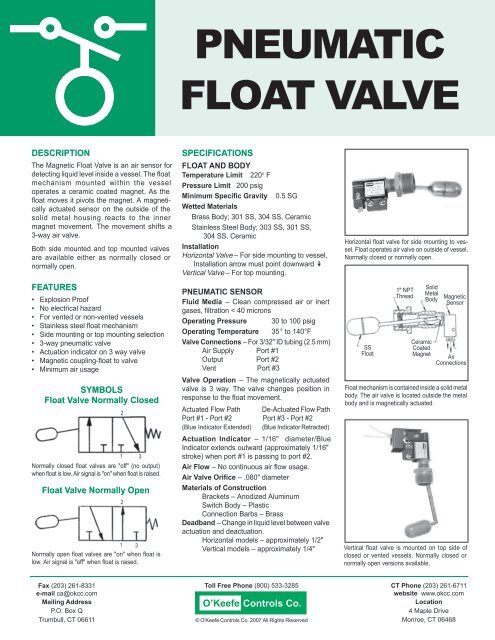
Horizontal float valve for side mounting to vessel.<br />
Float operates air valve on outside of vessel.<br />
Normally closed or normally open.<br />
SS<br />
Float<br />
1" NPT<br />
Thread<br />
Solid<br />
Metal<br />
Body<br />
Ceramic<br />
Coated<br />
Magnet<br />
Magnetic<br />
Sensor<br />
Air<br />
Connections<br />
Float mechanism is contained inside a solid metal<br />
body. The air valve is located outside the metal<br />
body and is magnetically actuated.<br />
Vertical float valve is mounted on top side of<br />
closed or vented vessels. Normally closed or<br />
normally open versions available.<br />
Fax (203) 261-8331<br />
e-mail ca@okcc.com<br />
Mailing Address<br />
P.O. Box Q<br />
Trumbull, CT 06611<br />
Toll Free Phone (800) 533-3285<br />
O’Keefe <strong>Controls</strong> Co.<br />
© <strong>O'Keefe</strong> <strong>Controls</strong> Co. 2007 All Rights Reserved<br />
CT Phone (203) 261-6711<br />
website www.okcc.com<br />
Location<br />
4 Maple Drive<br />
Monroe, CT 06468
<strong>PNEUMATIC</strong> <strong>FLOAT</strong> <strong>VALVE</strong><br />
HORIZONTAL <strong>FLOAT</strong> <strong>VALVE</strong> – SIDE MOUNTING VERTICAL <strong>FLOAT</strong> <strong>VALVE</strong> – TOP MOUNTING<br />
Normally Closed – Signal On Rising Level<br />
Normally Closed – Signal On Rising Level<br />
6-7/8""<br />
1-3/8" Hex<br />
TUBING<br />
NOT<br />
INCLUDED<br />
TUBING<br />
NOT INCLUDED<br />
Cable Clamp Bracket<br />
OKC-1532 Optional<br />
1-3/8" Hex<br />
7-11/16"<br />
1" NPT<br />
1" NPT<br />
1" Dia. x 2" Lg. Float<br />
SYMBOL N.C.<br />
2<br />
Cable Clamp Bracket<br />
OKC-1532 Optional<br />
1" Dia. x 2" Lg.<br />
Float<br />
SYMBOL N.C.<br />
2<br />
1 3<br />
1 3<br />
PART NUMBERS<br />
Catalog No. Body Installation State Float Max. Float Pressure<br />
OKC-1536-1 Brass Side Mounting N.C. Stainless Steel 200 psig<br />
OKC-1536-2 Stainless Steel Side Mountin<br />
N.C. Stainless Steel 200 psig<br />
OKC-1570-1 Brass Top Mounting N.C. Stainless Steel 200 psig<br />
OKC-1570-2 Stainless Steel Top Mounting<br />
N.C. Stainless Steel 200 psig<br />
OKC-2250-1 Brass Side Mounting N.O. Stainless Steel 200 psig<br />
OKC-2250-2 Stainless Steel Side Mounting N.O. Stainless Steel 200 psig<br />
OKC-2271-1 Brass Top Mounting N.O. Stainless Steel 200 psig<br />
OKC-2271-2 Stainless Steel Top Mounting N.O. Stainless Steel 200 psig<br />
HORIZONTAL <strong>FLOAT</strong> <strong>VALVE</strong> – SIDE MOUNTING<br />
Normally Open – Signal On Falling Level<br />
VERTICAL <strong>FLOAT</strong> <strong>VALVE</strong> – TOP MOUNTING<br />
Normally Open – Signal On Falling Level<br />
Cable Clamp Bracket<br />
OKC-1532 Optional<br />
TUBING<br />
NOT<br />
INCLUDED<br />
1" NPT<br />
2-7/8"<br />
1" Dia. x 2" Lg.<br />
Float<br />
Cable Clamp Bracket<br />
OKC-1532 Optional<br />
1-3/8" Hex<br />
7-11/16"<br />
1" NPT<br />
1" NPT<br />
6-7/8"<br />
1-3/8" Hex<br />
1" Dia. x 2" Lg. Float<br />
SYMBOL N.O.<br />
2<br />
TUBING<br />
NOT INCLUDED<br />
SYMBOL N.O.<br />
2<br />
1 3<br />
1 3<br />
O’Keefe<br />
<strong>Controls</strong> Co.<br />
© <strong>O'Keefe</strong> <strong>Controls</strong> Co. 2007 All Rights Reserved
LEVEL INDICATOR AND CONTROL APPLICATIONS<br />
HIGH LEVEL INDICATOR<br />
Normally Closed<br />
Float Valve<br />
Fill<br />
LOW LEVEL INDICATOR<br />
Fill<br />
Indicator<br />
2<br />
1<br />
Indicator<br />
Air In<br />
Signal "On" (Port 2)<br />
when level is high.<br />
Air In<br />
1 2<br />
Normally<br />
Open<br />
Float Valve<br />
Drain<br />
Drain<br />
Normally closed float valve (side or top mounted). Output signal<br />
(port 2) of level sensor is "on" when level is high. Output can actuate<br />
an indicator, pressure switch, air pilot power valve, etc. Can be<br />
used with High Level Indicator panel shown on page 4.<br />
Normally open float valve (side or top mounted). Output signal (port<br />
2) of level sensor is "on" when level is low. Output can actuate an<br />
indicator, pressure switch, air pilot power valve, etc. Can be used<br />
with Low Level Indicator panel shown on page 4.<br />
LEVEL CONTROL – WIDEBAND<br />
LEVEL CONTROL – NARROWBAND<br />
Fill Valve<br />
Fill<br />
Fill Valve<br />
Fill<br />
Normally Closed<br />
Float Valve<br />
2<br />
1<br />
Air In<br />
2<br />
1<br />
Air In<br />
Air In<br />
Normally Open<br />
Float Valve<br />
Detented<br />
Air Valve<br />
1<br />
2<br />
Normally Open<br />
Air In<br />
Float Valve<br />
Drain<br />
Drain<br />
Two level sensors required; one normally closed for high level, one<br />
normally open for low level. The control automatically maintains the<br />
level between the location of the two sensors. Minimum "high/low"<br />
is approximately two inches. Maximum "high/low" is set by the location<br />
of the two sensors. Can be used with Wideband Level Control<br />
panel on page 4.<br />
One normally open float valve provides the control for narrowband<br />
level control. Level is maintained within approximately 1/2". Output<br />
can actuate an air operated power valve for direct fill, or for control<br />
of an air operated pump through an air operated power valve. The<br />
output can be used with the Narrowband Level Control panel shown<br />
on page 4.<br />
O’Keefe <strong>Controls</strong> Co.<br />
© <strong>O'Keefe</strong> <strong>Controls</strong> Co. 2007 All Rights Reserved
Air In<br />
Air In<br />
HIGH LEVEL INDICATOR<br />
LOW LEVEL INDICATOR<br />
To High<br />
Level Sensor<br />
To Low<br />
Level Sensor<br />
HIGH LEVEL INDICATOR<br />
This panel is used for indication of level only. When<br />
a normally closed float valve is actuated by high<br />
liquid level the indicator shows "red". The indicator<br />
shows green when the float valve is not actuated.<br />
Part No. OKC-2289F <strong>Inc</strong>ludes inlet filter, regulator<br />
and gage assembly.<br />
Part No. OKC-2289 Filter, regulator and gage not<br />
included.<br />
Use the high level indicator panel with a normally<br />
closed float valve.<br />
OKC-1536-1 OKC-1570-1<br />
OKC-1536-2 OKC-1570-2<br />
LOW LEVEL INDICATOR<br />
This panel is used for indication of level only. When<br />
a normally open float valve is deactuated by low<br />
liquid level the indicator shows "red". The indicator<br />
shows green when the float valve is actuated by the<br />
liquid level.<br />
Part No. OKC-2290F <strong>Inc</strong>ludes inlet filter, regulator<br />
and gage assembly.<br />
Part No. OKC-2290 Filter, regulator and gage not<br />
included.<br />
SPECIFICATIONS<br />
Operation – A pneumatic<br />
indicator panel<br />
Box Dimensions –<br />
4-1/2" x 2-7/8" x 2-5/8"<br />
Inlet Air Pressure to Regulator –<br />
50-125 psig<br />
Normal Pressure Setting –<br />
50-100 psig<br />
Pneumatic Indicator –<br />
1" diameter red/green<br />
Manual Control –<br />
OFF/ON Toggle Valve<br />
Air Filtration – Air should be dry<br />
and filtered to 5 microns<br />
Use the low level indicator panel with a normally<br />
open float valve.<br />
OKC-2250-1 OKC-2271-1<br />
OKC-2250-2 OKC-2271-2<br />
Air In<br />
Air In<br />
Form OK-242R2<br />
WIDEBAND LEVEL CONTROL<br />
To Control Valve<br />
or Pump<br />
NARROWBAND LEVEL CONTROL<br />
To Control Valve<br />
or Pump<br />
To High<br />
Level Sensor<br />
To Low<br />
Level Sensor<br />
To Level<br />
Sensor<br />
WIDEBAND LEVEL CONTROL<br />
This panel is used for control of liquid between two<br />
levels. The control panel pilots a fill or drain valve, or<br />
controls a power valve that operates a pump. A normally<br />
closed float valve is used to sense the high level. A<br />
normally open float valve is used to sense the low level.<br />
Part No. OKC-2291F <strong>Inc</strong>ludes inlet filter, regulator<br />
and gage assembly.<br />
Part No. OKC-3171F (same as OKC-2291F but configured<br />
for “Pump Down” operations.)<br />
OKC-2291F panel indicator shows green after the high<br />
level is reached and continues to indicate green until the<br />
low level is reached. After the low level sensor is<br />
deactuated the indicator shows "red" until the high level<br />
sensor is actuated. (OKC-3171F shows "red" during pump<br />
down.)<br />
When the panel indicator shows "green" the output<br />
signal is "off". When the panel indicator shows "red" the<br />
output signal is "on."<br />
NARROWBAND LEVEL CONTROL<br />
This panel is used for control of liquid level over the<br />
deadband of the pneumatic float valve (approximately<br />
1/4" to 1/2"). The control panel pilots a fill or drain valve<br />
that operates a pump. A normally open float valve is used.<br />
The output control is "on" (indicator red) when the level is<br />
low and is "off" when the level is high (indicator green).<br />
Part No. OKC-2292F <strong>Inc</strong>ludes inlet filter, regulator<br />
and gage assembly.<br />
Part No. OKC-2292 Filter, regulator and gage not<br />
included.<br />
The output signal can also be used as a remote<br />
indicator signal to operate a visual indicator or a sonic<br />
alarm. Use as follows:<br />
Low Level Alarm – use a normally open float valve<br />
High Level Alarm – use a normally closed float valve<br />
O’Keefe <strong>Controls</strong> Co.<br />
© <strong>O'Keefe</strong> <strong>Controls</strong> Co. 2007 All Rights Reserved<br />
SPECIFICATIONS<br />
Operation – A pneumatic control<br />
panel<br />
Box Dimensions –<br />
4" x 4" x 2-5/8"<br />
Inlet Air Pressure to Regulator –<br />
50-125 psig<br />
Normal Pressure Setting –<br />
50-100 psig<br />
Pneumatic Indicator –<br />
1" diameter red/green<br />
Manual Control –<br />
OFF/ON Toggle Valve<br />
Air Filtration – Air should be dry<br />
and filtered to 5 microns<br />
Output Air Signal – 50-100 psig<br />
(same as regulator pressure<br />
setting)