High Rate Sand Filters - Rick English - Swimming Pool Consultant
High Rate Sand Filters - Rick English - Swimming Pool Consultant
High Rate Sand Filters - Rick English - Swimming Pool Consultant
Create successful ePaper yourself
Turn your PDF publications into a flip-book with our unique Google optimized e-Paper software.
BACKWASH<br />
Aquatools<br />
.WATERFORD, WI.<br />
53185<br />
USA<br />
RECIRCULATE<br />
FILTER<br />
E<br />
WASTE<br />
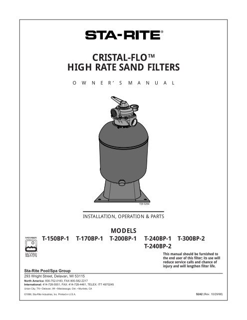
CRISTAL-FLO TM<br />
HIGH RATE SAND FILTERS<br />
O W N E R’ S<br />
M A N U A L<br />
729 0294<br />
INSTALLATION, OPERATION & PARTS<br />
MODELS<br />
T-150BP-1 T-170BP-1 T-200BP-1 T-240BP-1 T-300BP-2<br />
T-240BP-2<br />
Sta-Rite <strong>Pool</strong>/Spa Group<br />
293 Wright Street, Delavan, WI 53115<br />
North America: 800-752-0183, FAX 800-582-2217<br />
International: 414-728-5551, FAX: 414-728-4461, TELEX: ITT 4970245<br />
Union City, TN • Delavan, WI • Mississauga, Ont. • Murrieta, CA<br />
This manual should be furnished to<br />
the end user of this filter; its use will<br />
reduce service calls and chance of<br />
injury and will lengthen filter life.<br />
©1998, Sta-Rite Industries, Inc. Printed in U.S.A. S242 (Rev. 10/29/98)
HIGH RATE SAND FILTERS<br />
To avoid unneeded service calls, prevent possible injuries, and get the most<br />
out of your filter, READ THIS MANUAL CAREFULLY!<br />
The Sta-Rite Top Mounted Series <strong>High</strong> <strong>Rate</strong> <strong>Sand</strong> Filter:<br />
• Is designed to filter water for swimming pools.<br />
• Is an excellent performer; durable, reliable.<br />
Table of Contents<br />
Safety Instructions .......................................................................................2-3<br />
Dimensions/Specifications..............................................................................4<br />
General Information .......................................................................................5<br />
Installation ..................................................................................................5-7<br />
Filter Mount/Piping......................................................................................5<br />
Filter Set-up.................................................................................................6<br />
Loading <strong>Sand</strong> Media....................................................................................6<br />
Valve Installation.........................................................................................6<br />
Startup/Operation........................................................................................7<br />
Maintenance ..................................................................................................8<br />
Water Maintenance .....................................................................................8<br />
Storage/Winterizing...................................................................................8-10<br />
Mult-Port Valve Service ...............................................................................9<br />
Drain Fitting Installation/Removal .............................................................10<br />
Troubleshooting Guide .................................................................................11<br />
Repair Parts List.......................................................................................12-13<br />
Pressure Drop Curve ....................................................................................14<br />
Warranty ......................................................................................................15<br />
READ AND FOLLOW SAFETY<br />
INSTRUCTIONS!<br />
This is the safety-alert symbol. When you see this symbol on your valve<br />
or in this manual, look for one of the following signal words and be alert to the<br />
potential for personal injury.<br />
warns about hazards that will cause serious personal injury,<br />
death or major property damage if ignored.<br />
warns about hazards that can cause serious personal injury,<br />
death or major property damage if ignored.<br />
warns about hazards that will or can cause minor personal injury<br />
or property damage if ignored.<br />
The label NOTICE indicates special instructions which are important but not<br />
related to hazards.<br />
Carefully read and follow all safety instructions in this manual and on filter.<br />
Keep safety labels in good condition.<br />
Replace missing or damaged safety labels.<br />
2
Incorrectly installed or tested equipment may fail, causing severe<br />
injury or property damage. Read and follow instructions<br />
in owner's manual when installing and operating equipment.<br />
Have a trained pool professional perform all pressure tests.<br />
1. Do not connect system to a high pressure or city water system.<br />
2. Use equipment only in a swimming pool installation.<br />
3. Trapped air in system can cause explosion. BE SURE all air is out of system<br />
before operating or testing equipment.<br />
Before pressure testing, make the following safety checks:<br />
• Check all clamps, bolts, lids, and system accessories before testing.<br />
• BE SURE all air is out of system before testing.<br />
• Tighten Sta-Rite trap lids to 30 ft. lbs. (4.1 kg-cm) torque for testing.<br />
• Water pressure for test must be less than 25 PSI (172 kPa).<br />
• Water temperature for test must be less than 95˚ F. (35˚ C).<br />
• Limit test to 24 hours. After test, visually check system to be sure it is ready<br />
for operation. Remove trap lid and retighten hand tight only.<br />
NOTICE: These parameters apply to Sta-Rite equipment only. For<br />
non-Sta-Rite equipment, consult manufacturer.<br />
BEFORE WORKING<br />
ON FILTER:<br />
Hazardous Pressure!<br />
Can cause severe<br />
injury or major<br />
property damage from<br />
tank explosion.<br />
1. Stop pump.<br />
2. Open air release<br />
valve.<br />
3. Release all pressure<br />
from system.<br />
BEFORE WORKING<br />
ON PUMP OR MOTOR<br />
Filter pumps require<br />
hazardous voltage<br />
which can shock,<br />
burn, or cause death.<br />
Disconnect power to<br />
motor.<br />
3
Pump Inlet 1-1/2"<br />
Waste Outlet 1-1/2"<br />
Union connection<br />
See Page 14 for Pressure Drop Curve.<br />
Return Outlet<br />
1-1/2" Slip<br />
2.88 (73)<br />
RECOMMENDED SAND GRADES:<br />
Use only: #20 Silica <strong>Sand</strong>, Size Range .40-.55mm., Uniformity Coefficient less<br />
than 1.75.<br />
NOTICE: Use of other sands will reduce filter performance, may damage<br />
pump, and will void warranty.<br />
C Dia.<br />
D<br />
A<br />
B<br />
Recommended:<br />
1. Wedron Silica/Best <strong>Sand</strong> Co., <strong>Sand</strong> Grade: Wedron .45-.55mm., Effective<br />
Size .46mm, Uniformity Coefficient 1.22.<br />
2. U.S. Silica - Silurian Filter <strong>Sand</strong>, <strong>Sand</strong> Grade.45-.55 mm., Effective Size<br />
.48mm, Uniformity Coefficient 1.18.<br />
E,F<br />
1355 1094<br />
Fig. 1: Dimensions, T-150BP-1,<br />
T-170BP-1 T-200BP-1, T240BP-1<br />
2" NPT Inlet<br />
(Pump)<br />
2" NPT<br />
Outlet<br />
(Return)<br />
C<br />
E,F<br />
2" NPT Outlet<br />
(Waste)<br />
9.25 (235)<br />
D<br />
A<br />
8.00(203)<br />
1356 1094<br />
Fig. 2: Dimensions, T-300BP-2,<br />
T240BP-2<br />
B<br />
TABLE I - FILTER OPERATIONAL DATA<br />
Max.<br />
Filter Filter Flow <strong>Rate</strong><br />
Model Size in GPM (L/M)<br />
Dia. in Area in Ft 2<br />
Inches (mm) (M 2 )<br />
T-150BP-1 15 (381) 1.26 (.117) 25.2 (95)<br />
T-170BP-1 17 (432) 1.57 (.146) 31.5 (123)<br />
T-200BP-1 20 (508) 2.18 (.203) 43.6 (165)<br />
T-240BP-1 24 (610) 3.10 (.288) 62.0 (234.7)<br />
T-240BP-2 24 (610) 3.10 (.288) 62.0 (234.7)<br />
T-300BP-2 30 (762) 4.90 (.455) 98 (371)<br />
Turnover in Hours<br />
<strong>Sand</strong><br />
Filter<br />
Volume<br />
Model 6 8 10 12 in lbs. (kg.)<br />
gal. (L) gal. (L) gal. (L) gal. (L)<br />
T-150BP-1 9,070(34 330) 12,100(45 799) 15,120(57 229) 18,144(68 675) 100 (45.4)<br />
T-170BP-1 11,340(42 922) 15,120(57 229) 18,900(71 536) 22,680(85 844) 150 (68)<br />
T-200BP-1 15,700(59 424) 20,930(79 220) 26,160(99 016) 31,390(118 811) 200 (90.7)<br />
T-240BP-1 22,230(84 481) 29,760(112 642) 37,200(140 802) 44,640(168 962) 300 (136)<br />
T-240BP-2 22,230(84 481) 29,760(112 642) 37,200(140 802) 44,640(168 962) 300 (136)<br />
T-300BP-2 35,280(133 535) 47,040(178 046) 58,800(222 558) 70,560(267 070) 600 (272)<br />
*NOTE: 1 cubic foot of sand weighs approx. 100 lbs. (45.4 kg). Do not use finer or<br />
coarser grade than recommended for best performance.<br />
TABLE II - DIMENSIONAL DATA In Inches (mm)<br />
Base Base Piping<br />
Width Length Port<br />
Filter Model No. A B C D (E) (F) Size<br />
T-150BP-1 27 (686) 33-13/16 (859) 15-3/4 (400) 24-11/16 (627) 13 (330) 16-1/4 (413) 1-1/2” SLIP<br />
T-170BP-1 29-9/16 (751) 36-3/8 (924) 17-3/4 (451) 27-1/4 (692) 13 (330) 16-1/4 (413) 1-1/2” SLIP<br />
T-200BP-1 31-5/8 (803) 38-1/2 (978) 20-3/4 (527) 29-3/8 (746) 13 (330) 16-1/4 (413) 1-1/2” SLIP<br />
T-240BP-1 35-3/16 (897) 42 (1067) 24-3/4 (629) 32-7/8 (835) 16-7/8 (429) 21 (533) 1-1/2” SLIP<br />
T-240BP-2 35-1/4 (895) 44-1/2 (1130) 24-3/4 (629) 32-7/8 (835) 16-7/8 (429) 21 (533) 2” (NPT)<br />
T-300BP-2 42 (1067) 51-1/4 (1302) 31 (787) 39-5/8 (1008) 16-7/8 (429) 21 (533) 2” (NPT)<br />
4
GENERAL INFORMATION<br />
• Clean a new pool as well as possible before filling pool and operating filter.<br />
Excess dirt and large particles of foreign matter in the system can cause serious<br />
damage to the filter and pump.<br />
NEVER test this filter with compressed air.<br />
Do not operate filter at water temperatures above 95°F (35°C).<br />
NEVER operate this filter system at more than 50 pounds per square inch<br />
(50 PSI/345 kPa) pressure!<br />
INSTALLATION<br />
Installation of filter should only be done by qualified, licensed personnel.<br />
For assembly and filling instructions, see page 6.<br />
Filter mount must:<br />
• Provide weather and freezing protection.<br />
• Provide space and lighting for easy access for routine maintenance. (See<br />
Figures 1 and 2, Table II, Page 4, for space requirements.)<br />
• Be on a reasonably level surface and provide adequate drainage.<br />
• Be as close to pool as possible to reduce line loss from pipe friction.<br />
Piping:<br />
• Piping must conform to local/state plumbing and sanitary codes.<br />
• Use pipe joint sealing compound or teflon tape on all male connections of<br />
metal pipe and fittings (except unions). Use teflon tape or Plasto-Joint Stik 1 on<br />
all male connections of plastic pipe and fittings. DO NOT use pipe dope on<br />
plastic pipe; it will cause the pipe to crack. Do not use sealant or tape on<br />
unions – assemble them dry and hand tight.<br />
• Do not damage union sealing surfaces and “O” Rings.<br />
• Support pipe independently to prevent strains on filter or valve.<br />
• Use 1-1/2 or 2” pipe to reduce pressure losses as much as possible.<br />
NOTICE: Filter may be located away from pool, but for adequate flow larger<br />
pipe may be needed. Check local codes when considering remote installation.<br />
• Fittings restrict flow; for best efficiency use fewest possible fittings.<br />
• Keep piping tight and free of leaks: pump suction line leaks may cause trapped<br />
air in filter tank or loss of prime at pump; pump discharge line leaks may show<br />
up as dampness or jets of water.<br />
• When unions are provided, use as follows for leak free connections:<br />
1. O-Ring and sealing surfaces must be clean.<br />
2. Assemble hand tight only (no wrenches).<br />
3. No pipe compound or teflon tape on unions.<br />
Valves:<br />
• A check valve installed between filter and heater will prevent hot water from<br />
backing up into filter and deforming internal components.<br />
• Use care before assembly not to damage union sealing surfaces or O Ring.<br />
Wastewater:<br />
• Be sure all provisions for waste water disposal meet applicable local, state or<br />
national codes. 100 gallons (379 liters) or more of pool water will be discharged<br />
during filter backwashing. Do not discharge where water will cause<br />
flooding or damage.<br />
1<br />
Lake Chemical Co., Chicago, IL<br />
5
Fig. 2<br />
C. Hold assembly up<br />
near top of tank and<br />
add remaining<br />
laterals.<br />
732 0294<br />
Fig. 3<br />
D. After all<br />
laterals are<br />
securely in<br />
sockets,<br />
position<br />
assembly on<br />
centering<br />
boss in<br />
bottom of<br />
tank.<br />
Fig. 4<br />
Fill tank<br />
about<br />
half full<br />
of water<br />
before<br />
adding<br />
sand.<br />
A. Insert first lateral into socket;<br />
twist clockwise 1/4 turn<br />
to lock lateral into hub.<br />
Lateral is correctly installed<br />
when slots face down.<br />
SAND<br />
::::<br />
::::<br />
::::<br />
::::<br />
::::<br />
:::::::<br />
::::::::<br />
::::::::<br />
:::: :::: :::: ::::<br />
:::: :::: ::::<br />
:::: :::: ::::<br />
::::<br />
:::: :::: :::: ::::<br />
:::: :::: :::: :::: :::: :::: ::::<br />
:::: :::: ::::<br />
:::: ::::<br />
:::: :::: ::::<br />
::::<br />
:::: ::::<br />
::::<br />
::::<br />
::::<br />
::::<br />
::::<br />
::::<br />
::::::::<br />
::::<br />
::::<br />
:::: ::::<br />
:::: ::::<br />
::::<br />
::::<br />
::::<br />
::::<br />
::::<br />
::::<br />
::::<br />
::::<br />
::::<br />
::::<br />
::::<br />
:::: :::: ::::<br />
:::: :::: ::::<br />
:::: :::: :::: :::: :::: :::: :::: :::: ::::<br />
:::: :::: ::::<br />
:::: :::: ::::<br />
B. Insert assembly<br />
into top of<br />
filter tank.<br />
733 0294<br />
731 0294<br />
<strong>Sand</strong> Shield<br />
keeps collector<br />
hub assembly<br />
clean when<br />
loading filter.<br />
Filter Setup<br />
Assembly: See Figures 2 through 5 for filter assembly.<br />
Loading <strong>Sand</strong> Media<br />
1.To keep sand out of collector assembly, place plastic sand shield over top<br />
of collector tube before pouring sand into filter (See Figure 5).<br />
2.To support laterals and prevent lateral breakage during loading, fill tank<br />
about half full of water before loading sand.<br />
3.Pour sand into filter tank. See Page 4, for correct type and quantity of sand<br />
to use.<br />
NOTICE: Make sure gasket area on top of tank is free of sand before installing<br />
valve and clamp.<br />
4.Before installing valve, double-check that correct quantity of sand has<br />
been loaded (see Page 4).<br />
5.Remove plastic sand loading shield and keep for future use.<br />
Valve Installation:<br />
See Figures 6, 7, and 8<br />
1. Install O-Ring on valve flange; make sure O-Ring is clean, dry, and has<br />
no nicks, tears, or scrapes.<br />
2. Make sure tank and valve flanges are clean and free of sand; put valve<br />
on top of tank. Vertical pipe of collector assembly inserts into base of<br />
valve.<br />
3.Install clamp; make sure knob is positioned for easy access for filter<br />
maintenance. Valve port labeled “PUMP” should point toward pump.<br />
4.Tighten clamp knob until clamp ends (under bolt) are 1/4” (6mm) apart.<br />
Tap around outside of clamp with a mallet to help seat clamp.<br />
Hazardous pressure. Clamp will not hold unless it is<br />
seated properly! DO NOT START PUMP until clamp ends are 1/4”<br />
(6mm) apart or less.<br />
5.If clamp will not pull up to 1/4” (6mm) gap, wait 15-30 minutes and<br />
retighten. Tap clamp gently with mallet to help seat clamp.<br />
6.Connect pipe from pump discharge to valve port labeled “PUMP”; use<br />
union half provided. Assemble union as follows for leakfree operation:<br />
A. O-Ring and sealing surfaces must be clean.<br />
B. Assemble hand tight only (no wrenches).<br />
C. NO pipe compound or teflon tape on unions.<br />
7.Complete all plumbing connections (see Page 5 for piping requirements).<br />
A. Pipe from valve RETURN port to pool return.<br />
B. Pipe from valve WASTE port to waste.<br />
C. Suction piping from pool to trap inlet on pump.<br />
8.System is ready for startup.<br />
NOTICE: If there are leaks from beneath valve/clamp area, STOP<br />
PUMP, release all pressure, remove clamp and valve and clean sealing<br />
surfaces.<br />
Fig. 5<br />
734 0294<br />
6
Aquatools<br />
.WATERFORD, WI.<br />
53185<br />
USA<br />
FILTER<br />
E<br />
Aquatools<br />
.WATERFORD, WI.<br />
53185<br />
USA<br />
FILTER<br />
E<br />
Startup/Operation (See Figure 9)<br />
BACKWASH<br />
RECIRCULATE<br />
WASTE<br />
Hazardous pressure. To avoid explosion and possible severe<br />
or fatal injury, filter system pressure must not exceed 50 PSI (345<br />
kPa) under any circumstances. NEVER test this filter system with compressed<br />
air; never operate system with water temperature above 95° F<br />
(35° C).<br />
. Install O-Ring<br />
on valve flange.<br />
Install valve on tank.<br />
Tank flange must<br />
be clean; insert<br />
collector pipe<br />
into bottom<br />
of valve.<br />
Fig. 6<br />
ort labeled<br />
PUMP" should<br />
oint toward<br />
ump.<br />
1/4" Max.<br />
Fig. 7<br />
Install clamp<br />
and tighten<br />
until clamp<br />
ends (under<br />
bolt) are 1/4"<br />
apart.<br />
BACKWASH<br />
RECIRCULATE<br />
WASTE<br />
If unable to<br />
close gap<br />
to 1/4" or less,<br />
wait 15-30<br />
minutes and<br />
retighten.<br />
Tap around<br />
clamp while<br />
tightening to<br />
help seat<br />
clamp.<br />
736 0294<br />
To prevent equipment damage and possible injury, turn<br />
pump OFF before changing valve position.<br />
NOTICE: Do not add chemicals directly into the pool skimmer. Adding<br />
undiluted chemicals may damage equipment and void warranty.<br />
1. Open system valves and make sure pump is filled with water. Make<br />
sure pool water level is 2” (51mm) above bottom of skimmer opening.<br />
2. With pump OFF, set valve to ‘BACKWASH’ position.<br />
3. Start pump, circulating water backwards through filter to waste.<br />
NOTICE: To prevent pump from running dry, be sure water level<br />
never drops below bottom of skimmer inlet. Add water to pool if<br />
necessary to keep skimmer flooded while backwashing and rinsing.<br />
4. Backwash until water runs clear (3-5 minutes).<br />
5. Stop pump; set valve to ‘RINSE’ position.<br />
6. Start pump; run pump for one minute.<br />
7. Stop pump; set valve to ‘FILTER’ position.<br />
8. Filter is now ready for service.<br />
9. Record clean starting filter pressure gauge reading as a reference.<br />
10. When pool is first filled, backwash once a day until pool water is<br />
sparkling clear. After that, backwash when pressure gauge shows 5 to<br />
7 PSI (34.5 to 48 kPa) higher than starting pressure.<br />
Valve Setting<br />
Purpose/Flow<br />
Valve Setting<br />
Purpose/Flow<br />
Valve Setting<br />
Purpose/Flow<br />
WINTERIZE<br />
WASTE<br />
CLOSED<br />
FILTER<br />
BACKWASH<br />
RINSE<br />
RECIRCULATE<br />
FILTER<br />
Normal filtration and<br />
vacuuming; water goes<br />
through filter to pool.<br />
WINTERIZE<br />
CLOSED<br />
WASTE<br />
FILTER<br />
BACKWASH<br />
RINSE<br />
RECIRCULATE<br />
BACKWASH<br />
Reverses flow for<br />
cleaning; water<br />
goes through filter<br />
to waste.<br />
WINTERIZE<br />
WASTE<br />
CLOSED<br />
FILTER<br />
BACKWASH<br />
RINSE<br />
RECIRCULATE<br />
WASTE<br />
Lowers pool level or<br />
drains pool; water<br />
bypasses filter,<br />
goes to waste.<br />
WINTERIZE<br />
WASTE<br />
CLOSED<br />
FILTER<br />
BACKWASH<br />
RINSE<br />
RECIRCULATE<br />
RINSE<br />
For initial startup cleaning<br />
and sand bed leveling<br />
after backwash; water goes<br />
through filter to waste.<br />
WINTERIZE<br />
WASTE<br />
CLOSED<br />
FILTER<br />
BACKWASH<br />
RINSE<br />
RECIRCULATE<br />
CLOSED<br />
Shuts off all flow to<br />
filter and pool.<br />
g<br />
743 0294<br />
WINTERIZE<br />
CLOSED<br />
WASTE<br />
Fig. 8<br />
FILTER<br />
BACKWASH<br />
RINSE<br />
RECIRCULATE<br />
RECIRCULATE<br />
Circulates pool water;<br />
bypasses filter.<br />
737 029<br />
WINTERIZE<br />
WASTE<br />
CLOSED<br />
FILTER<br />
BACKWASH<br />
RINSE<br />
RECIRCULATE<br />
WINTERIZE<br />
Leaves all valve ports<br />
partially open for<br />
winter storage.<br />
738 029<br />
WINTERIZE<br />
CLOSED<br />
WASTE<br />
FILTER<br />
BACKWASH<br />
RINSE<br />
RECIRCULATE<br />
WINTERIZE<br />
WASTE<br />
CLOSED<br />
FILTER<br />
BACKWASH<br />
RINSE<br />
RECIRCULATE<br />
WINTERIZE<br />
WASTE<br />
CLOSED<br />
FILTER<br />
Fig. 9: Valve settings for startup. Stop<br />
pump before changing valve position.<br />
BACKWASH<br />
RINSE<br />
RECIRCULATE<br />
7
MAINTENANCE<br />
General:<br />
• Wash outside of filter with a mild detergent and water. Rinse off with hose.<br />
NOTICE: DO NOT use solvents to clean filter; solvents may damage plastic<br />
components in system.<br />
• Inspect sand bed at least once a year to remove foreign material which has not<br />
been backwashed out of system.<br />
NOTICE: When the sand bed gets hard and crusty on top, remove all the old<br />
sand and replace it with new sand.<br />
WINTERIZE<br />
WINTERIZE<br />
WASTE<br />
WASTE<br />
CLOSED<br />
CLOSED<br />
FILTER<br />
FILTER<br />
BACKWASH<br />
BACKWASH<br />
Fig. 10: Valve settings to lower<br />
pool water level. Stop pump<br />
before changing valve position.<br />
WINTERIZE<br />
WASTE<br />
CLOSED<br />
FILTER<br />
BACKWASH<br />
Fig. 11: Valve setting for winter<br />
storage. Stop pump before<br />
changing valve position.<br />
RINSE<br />
RINSE<br />
RINSE<br />
RECIRCULATE<br />
RECIRCULATE<br />
RECIRCULATE<br />
Weekly <strong>Pool</strong> Equipment Inspection:<br />
1. Check pressure during operation. When pressure is 5 to 7 PSI (34.5 to 48<br />
kPa) higher than initial operating pressure, backwash filter (see instructions<br />
under “Startup/Operation”, Page 7).<br />
2. Except during hot weather with heavy swimmer loads, operating filter 6 to 12<br />
hours per day should be sufficient. Carefully monitor water chemical balance<br />
and follow recommendations of your local pool professional.<br />
Water Maintenance<br />
• Keep water level at least 2” (51mm) above bottom of skimmer opening.<br />
Failure to do so can allow air to enter system, causing pump to lose prime<br />
and air to enter filter.<br />
• Maintain pH at 7.2 to 7.6 in pool.<br />
To prevent damage to system components, keep water temperature below<br />
95° F. (35° C) at all times.<br />
Vacuum <strong>Pool</strong>:<br />
1. Fill vacuum hose by submerging in water from one end to the other.<br />
2. To vacuum, insert hose into skimmer suction manifold or into vacuum line<br />
in pool wall. See instructions provided by pool builder or pool manufacturer.<br />
Start pump, making sure it is primed and pumping.<br />
3. After vacuuming, clean pump trap to remove accumulated debris, then<br />
check filter pressure gage. If reading is 5 to 7 PSI (34.5 to 48 kPa) higher<br />
than initial operating pressure, backwash filter.<br />
Lower or Drain <strong>Pool</strong><br />
1. Turn pump ‘OFF’; set valve handle to ‘WASTE’.<br />
2. Use vacuum cleaner hose and head.<br />
3. Start pump; run until pool is lowered to desired level.<br />
4. Turn pump ‘OFF’; set valve handle to ‘FILTER’.<br />
5. Start pump.<br />
STORAGE/WINTERIZING<br />
<strong>Pool</strong> chemicals may give off corrosive fumes. Store chemicals<br />
away from system in a well ventilated area.<br />
NOTICE: Allowing water to freeze will damage filter and void warranty. If antifreeze<br />
is needed, use propylene glycol; it’s plastic compatible and non-toxic.<br />
Follow manufacturers instructions. Do not use ethylene glycol based antifreeze<br />
– it’s toxic and it may damage plastic components.<br />
1. Open all system valves. Set multiport valve at ‘WINTERIZE’ to allow air passage<br />
to all ports.<br />
8
Aquatools<br />
.WATERFORD, WI.<br />
53185<br />
USA<br />
RINSE<br />
WINTERIZE<br />
RECIRCULATE<br />
FILTER<br />
1<br />
2<br />
3<br />
4<br />
5<br />
BACKWASH<br />
CLOSED<br />
WASTE<br />
1A<br />
2. Remove drain plug from filter.<br />
3. Drain filter tank completely and replace drain cap (Figure 13, Page 10).<br />
4. Cover with plastic or tarpaulin to protect from weather, but do not seal from<br />
air circulation.<br />
5. Protect from freezing.<br />
Startup for Winterized Equipment:<br />
1. Remove any temporary weather protection placed around system for shutdown.<br />
2. See “Startup”, Page 7, for reactivation of the filter.<br />
3. Inspect all electrical wiring to pump for damage or deterioration over the<br />
shutdown period. Have a qualified serviceman repair/replace wiring as<br />
needed. Inspect and tighten all watertight connections.<br />
4. Open all valves in suction and return piping.<br />
5. Remove any winterizing plugs in system.<br />
6. Drain all winterizing chemicals (if used) from system; flush system.<br />
7. Close all drain valves and replace all drain plugs in system (see Page 10).<br />
8. Fill pool with water to proper level (see pool maufacturer’s instructions).<br />
MULTI-PORT VALVE SERVICE<br />
6<br />
744 0294<br />
Fig. 12A: Valve Disassembly<br />
(1-1/2” Multiport Valve)<br />
5<br />
1344 1094<br />
Fig. 12B: Valve Disassembly<br />
(2” Multiport Valve)<br />
6<br />
1<br />
1A<br />
2<br />
3<br />
4<br />
Hazardous pressure. Stop pump and release all pressure from system<br />
before working on filter, valve, or clamp.<br />
NOTICE: if Multi-Port valve is below pool water level, close suction and discharge<br />
valves before disassembly to prevent draining pool.<br />
Handle Replacement:<br />
1. Stop pump.<br />
2. Place handle in ‘FILTER’ position.<br />
3. Remove pin (Key 1, Figures 12A and 12B) to disconnect handle. If it cannot<br />
be removed by hand, use a hammer and center punch and lightly tap it out.<br />
4. Remove handle; replace with a new one. Be sure new handle is in ‘FILTER’<br />
position.<br />
5. Replace pin.<br />
Lid and Plug replacement:<br />
1. Remove Handle (see ‘Handle Replacement’ above).<br />
2. Remove plug:<br />
A. Remove all screws and nuts (Key Nos. 2 and 6, Figures 12A and 12B).<br />
B. Remove lid (Key No. 3) by pulling straight up while holding plug shaft<br />
(Key No. 5) down with thumb.<br />
3. Inspect Internal Parts:<br />
Inspect plug and gasket spring, O-Rings, and internal washers (Key No. 4).<br />
Replace if necessary.<br />
4. Reassemble Valve:<br />
A. Replace plug gasket and shaft, mounting spring, washers, and O-Ring on<br />
plug shaft. Lubricate O-Ring with Amojel.<br />
B. Replace lid; match screw holes in lid and body.<br />
C. Press down on lid to allow screws to engage nuts; tighten each nut securely.<br />
D. Replace top washer (Key No. 1A) and handle, making sure indexing pin<br />
on plug shaft points in same direction as pointer on handle. Replace handle<br />
pin.<br />
E. Tighten all lid screws to 55 inch-lbs. (63.4 kg-cm) torque.<br />
9
Small<br />
O-Ring<br />
Open end<br />
of lateral<br />
About 1"<br />
Seat small<br />
O-Ring<br />
Large<br />
O-Ring<br />
End of lateral is<br />
flush with end of<br />
drain fitting 746 0294<br />
Figure 13: Drain Fitting Assembly.<br />
This assembly allows water to drain<br />
without losing the sand out of the filter<br />
tank.<br />
Make sure all surfaces are clean and<br />
free of sand. Don’t cross thread cap;<br />
don’t overtighten cap.<br />
Valve Removal<br />
Hazardous pressure. Stop pump and release all pressure from system<br />
before working on filter, valve, or clamp.<br />
NOTICE: If multi-Port Valve is below pool water level, close suction and discharge<br />
valves before disassembly to prevent draining pool.<br />
1. Disconnect piping from pump and pool.<br />
2. Remove clamp.<br />
3. Remove valve from filter top.<br />
4. To reinstall valve, follow instructions, Figures 6 and 7, Page 7. BE SURE to<br />
follow clamp tightening instructions.<br />
Drain Fitting Installation/Removal<br />
NOTICE: If pool is above height of filter, first close valves in pump suction and<br />
return lines to prevent draining pool. If there are no shutoff valves installed, disconnect<br />
suction and return lines and raise ends above pool water level.<br />
1. Installation: See Figure 13.<br />
2. To Drain Filter:<br />
A. Remove drain cap. Lateral tube should remain in place inside drain<br />
opening to prevent sand from draining out.<br />
B. Open union coupling on backwash port of Multi-Port valve. This will<br />
allow air into filter and allow water to drain from filter tank.<br />
C. Replace cap when tank is empty.<br />
3. Removing <strong>Sand</strong> From Filter:<br />
A. Remove both drain cap and slotted lateral tube (see Figure 13). <strong>Sand</strong> and<br />
water will drain from tank.<br />
B. To completely flush filter tank of sand, remove top clamp and multiport<br />
valve and flush the inside of the tank with a hose.<br />
C. Thoroughly clean sand from all parts and from tank drain opening before<br />
reassembling drain fitting.<br />
10
Hazardous pressure.<br />
Can cause severe injury<br />
or major property<br />
damage from tank<br />
blow up.<br />
Release all pressure<br />
and read instructions<br />
before working on filter.<br />
TROUBLESHOOTING GUIDE<br />
1. Short Cycle between backwashes:<br />
NOTICE: Time between backwashes will vary with each installation and between<br />
different areas of the country. Ask installer about normal backwash interval<br />
in your area. The following causes and remedies are for cycle times<br />
shorter than normal for your area.<br />
A. Flow rate too high or filter too small; consult dealer for system sizing recommendations.<br />
B. Water is chemically out of balance; consult pool serviceman.<br />
C. Excess dirt/dust in pool; vacuum pool directly to waste.<br />
D. Body oil/lotion build-up in filter; consult dealer for chemical filter cleaners<br />
and follow cleaner manufacturer’s instructions.<br />
E. Filter inadequately backwashed. See instructions under<br />
“Startup/Operation”, Page 7.<br />
F. Algae in pool. Consult pool professional about proper chemical maintenance.<br />
G. Residual chlorine level too low. Consult pool professional about proper<br />
chemical maintenance.<br />
H. Inspect filter sand for solidification caused by dust, calcium, skin oils, of<br />
suntan lotions.<br />
2. Low Flow:<br />
A. Pipe blocked downstream from filter; remove obstruction.<br />
B. Piping too small; use larger pipe (consult dealer for sizing).<br />
C. Plugged pump; plugged hair and lint trap or skimmer basket. Clean thoroughly.<br />
3. <strong>Pool</strong> Water Not Clear:<br />
A. Water is chemically out of balance; consult pool professional.<br />
B. Filter is too small; consult dealer about equipment sizing.<br />
C. <strong>Sand</strong> in pool means broken lateral. Drain both water and sand out of<br />
tank. Remove valve; follow procedure under “Filter Setup”, Page 6, and<br />
instructions with new lateral to replace broken part.<br />
To avoid severe injury or major property damage, follow<br />
instructions under 'Valve Installation', Figures 6 and 7, Page 7).<br />
1. Follow valve removal procedure, Page 10.<br />
2. Replace lateral according to instructions supplied with new lateral.<br />
3. Reassemble filter according to instructions under “Filter Setup”, Page 6.<br />
11
BACKWASH<br />
Aquatools<br />
.WATERFORD, WI.<br />
53185<br />
USA<br />
FILTER<br />
E<br />
WASTE<br />
REPAIR PARTS – TANKS<br />
T-150BP-1, T-170BP-1,<br />
T-200BP-1, T-240BP-1,<br />
T240BP-2, T-300BP-2<br />
1<br />
RECIRCULATE<br />
2<br />
3<br />
4<br />
5<br />
6<br />
7<br />
8<br />
13<br />
9<br />
10<br />
11<br />
12<br />
757 0294<br />
Model<br />
Key<br />
No.<br />
No. Description Used T-150BP-1 T-170BP-1 T-200BP-1 T-240BP-1 T-240BP-2 T-300BP-2<br />
1 Multiport Valve, Top Mount 1 WC112-148 WC112-148 WC112-148 WC112-148 14971-TM-22-L 14971-TM-22-L<br />
2 O-Ring, Valve Flange 1 U9-369 U9-369 U9-369 U9-369 U9-369 U9-369<br />
3 V-Clamp w/Knob 1 WC119-87A WC119-87A WC119-87A WC119-87A WC119-87A WC119-87A<br />
4 Clamp Knob 1 WC36-22 WC36-22 WC36-22 WC36-22 WC36-22 WC36-22<br />
5 Collector Hub Assembly 1 24200-0110 WC137-516P WC137-517P WC137-519P 24204-0029 24205-0010<br />
6 Lateral 8 24600-0003 24600-0003 24600-0003 24700-0075 21180-0163 21180-0100<br />
7 Filter Tank 1 24200-0100 24201-0100 24203-0100 24204-0100 24204-0100 24205-0100<br />
8 O-Ring, Lateral 1 U9-370 U9-370 U9-370 U9-370 U9-370 U9-370<br />
9 Drain Lateral 1 24201-0058 24201-0058 24201-0058 24201-0058 24201-0058 24201-0058<br />
10 O-Ring, Drain Cap 1 U9-371 U9-371 U9-371 U9-371 U9-371 U9-371<br />
11 Drain Cap 1 14965-0025 14965-0025 14965-0025 14965-0025 14965-0025 14965-0025<br />
12 Pedestal 1 23910-0005B 23910-0005B 23910-0005B 23900-0105B 23900-0105B 23900-0205<br />
13 Filter Tank Assembly 1 24200-0322E 24201-0322E 24203-0322E 24204-0322E 24204-0242 24205-0322E<br />
• Union Coupling Package 1 C198-5 C198-5 C198-5 C198-5 – –<br />
• <strong>Sand</strong> Loading Disc 1 24201-0043 24201-0043 24201-0043 24201-0043 24201-0063 24201-0063<br />
• Model & Instruction Label 1 32155-4115A 32155-4115B 32155-4115C 32155-4115D 90000-1328 32155-4115E<br />
• Clamp Warning Decal 1 32165-4030 32165-4030 32165-4030 32165-4030 32165-4030 32165-4030<br />
• Information Decal 1 32155-4112 32155-4112 32155-4112 32155-4112 32155-4112 32155-4112<br />
•Not Illustrated.<br />
12
STA-RITE<br />
STA-RITE IND., INC.<br />
WATERFORD, WI.<br />
53185<br />
USA<br />
RINSE<br />
WINTERIZE<br />
RECIRCULATE<br />
FILTER<br />
REPAIR PARTS – MULTI-PORT VALVES<br />
WC112-148<br />
#14971-TM-22-L<br />
1<br />
2<br />
2<br />
3<br />
4<br />
5<br />
CLOSED<br />
WASTE<br />
11<br />
3<br />
4<br />
BACKWASH<br />
6<br />
7<br />
8<br />
9A<br />
10<br />
9B<br />
12<br />
13<br />
14<br />
15<br />
16<br />
6<br />
7<br />
9A<br />
10<br />
8<br />
12<br />
11<br />
12A<br />
13<br />
14<br />
15<br />
18 17 16<br />
1343 1094<br />
Key Part<br />
No. Description Qty. WC112-148 14971-TM-22-L<br />
1 Valve Handle Decal 1 14965-0021 ––<br />
2 Handle 1 14962-0032 14971-SM10E1<br />
3 Dowel Pin 1 35857-0021 14971-SM10E2<br />
4 Washer 1 14965-0007 14971-SM10E3<br />
5 Operating Instruction Decal 1 14965-0020 ––<br />
6 Screw 37337-3056(7) 14971-SM10E4(10)<br />
7 Valve Cover 1 14965-0011 14971-SM20E6<br />
8 O-Ring 1 35505-1228 14971-SM10E10<br />
9A Washer 2 14965-0007 14971-SM10E8<br />
9B Washer 1 14965-0007 ––<br />
10 Spring 1 14965-0006 14971-SM10E9<br />
11 Pressure Guage 1 15060-0000T 15060-0000T<br />
12 Plug & Gasket Assembly 1 14965-0028 14971-SM20E11<br />
12A Gasket 1 –– 14971-SM20E12<br />
13 Cover O-Ring 1 35505-1275 14971-SM20E7<br />
14 Valve Body Assembly 1 14965-0013 14971-SM20E13<br />
15 Nut 35407-0071(7) 14971-SM10E14(10)<br />
16 Tank Flange O-Ring 1 U9-369 U9-369<br />
17 Sight Glass Gasket 1 –– 14971-SM20E17<br />
18 Sight Glass 1 –– 14971-SM10E16<br />
13
14<br />
T-240BP-1<br />
12<br />
T-300BP-2<br />
10<br />
T-150BP-1 T-170BP-1,<br />
T-200BP-1<br />
8<br />
P.S.I. Loss<br />
6<br />
4<br />
2<br />
0 20 40 60 80 100 120<br />
Capacity (GPM)<br />
Figure 14 – Pressure Drop Curve<br />
14
STA-RITE LIMITED WARRANTY<br />
Pumps, filters, skimmers, underwater lights (except bulbs),<br />
accessories and fittings manufactured by Sta-Rite are warranted<br />
to be free of defects in material and workmanship for<br />
one (1) year from date of installation.<br />
Product specific warranties:<br />
Year from date<br />
of installation<br />
HRPB, DEPB and System 3 – Tanks . . . . . . . . . . . .10 years<br />
Internal filter components and valves . . . . . . . . . 1 year<br />
Max-E-Therm – <strong>Pool</strong>/Spa Heaters . . . . . . . . . . . . . 2 years<br />
Heater Enclosure only (Upper RH & LH;<br />
lower enclosure; and control board enclosure)… 10 years<br />
Automatic <strong>Pool</strong> Cleaners including Hose . . . . . . . 2 years<br />
Cristal-Flo filters – Tanks . . . . . . . . . . . .10 years pro-rated*<br />
Valve and internal components. . . . . . . . . . . . . . . . 1 year<br />
Posi-Flo II – Tanks . . . . . . . . . . . . . . . . . . . . . . . . . .10 years<br />
Elements . . . . . . . . . . . . . . . . . . . . . . . . . . . . . . . . 1 year<br />
Waterford <strong>Sand</strong> – Tanks . . . . . . . . . . . . .10 years pro-rated*<br />
Pumps . . . . . . . . . . . . . . . . . . . . . . . . . . . . . . . . . . 1 year<br />
Valve and Internals . . . . . . . . . . . . . . . . . . . . . . . . . 1 year<br />
Waterford Cartridge – Filter Tank . . . . . . . . . . . . .10 years<br />
Pumps . . . . . . . . . . . . . . . . . . . . . . . . . . . . . . . . . . 1 year<br />
System 3 Above Ground Systems – Tanks . . . . . . .10 years<br />
Pumps . . . . . . . . . . . . . . . . . . . . . . . . . . . . . . . . . . 1 year<br />
Platform and Internals . . . . . . . . . . . . . . . . . . . . . . 1 year<br />
Pumps . . . . . . . . . . . . . . . . . . . . . . . . . . . . . . . . . . . . . 1 year<br />
When equipped with A.O. Smith<br />
2-compartment motors (Does not include<br />
pumps sold as part of a systems package) . . . . . . 2 years<br />
* Full warranty coverage is in effect for one year after installation.<br />
The pro-rated warranty covers the tank only during<br />
the 2nd through 10th year after installation. The amount covered<br />
decreases by 10% each year. (ie., 2nd year 90% covered,<br />
3rd year 80% covered, etc.).<br />
The foregoing warranties relate to the original consumer purchaser<br />
(“Purchaser”) only. Sta-Rite shall have the option to repair<br />
or replace the defective product, at its sole discretion.<br />
Purchasers must pay all labor and shipping charges necessary<br />
to replace the product covered by this warranty.<br />
Requests for warranty service must be made through the installing<br />
dealer. This warranty shall not apply to any product<br />
that has been subject to negligence, misapplication, improper<br />
installation or maintenance, or other circumstances<br />
which are not in Sta-Rite’s direct control.<br />
This warranty sets forth Sta-Rite’s sole obligation and<br />
Purchaser’s exclusive remedy for defective products.<br />
STA-RITE SHALL NOT BE LIABLE FOR ANY CONSEQUEN-<br />
TIAL, INCIDENTAL OR CONTINGENT DAMAGES WHATSO-<br />
EVER.<br />
THE FOREGOING WARRANTIES ARE EXCLUSIVE AND IN<br />
LIEU OF ALL OTHER EXPRESS WARRANTIES. IMPLIED WAR-<br />
RANTIES, INCLUDING BUT NOT LIMITED TO THE IMPLIED<br />
WARRANTIES OF MERCHANTABILITY AND FITNESS FOR A<br />
PARTICULAR PURPOSE, SHALL NOT EXTEND BEYOND THE<br />
DURATION OF THE APPLICABLE EXPRESS WARRANTIES<br />
PROVIDED HEREIN.<br />
Some states do not allow the exclusion or limitation of incidental<br />
or consequential damages or limitations on how long<br />
an implied warranty lasts, so the above limitations or exclusion<br />
may not apply to you. This warranty gives you specific<br />
legal rights and you may also have other rights which vary<br />
from state to state.<br />
Supersedes all previous publications.<br />
Sta-Rite Industries, Inc.<br />
293 Wright Street<br />
Delavan, WI 53115<br />
▲ Retain Warranty Certificate (upper portion) in a safe and convenient location for your records.<br />
DETACH HERE: Fill out bottom portion completely and mail within 10 days of purchase/installation to:<br />
▼ Sta-Rite, Attn: Warranty Dept., 293 Wright St., Delavan, WI 53115<br />
Warranty Registration Card<br />
Name<br />
Address<br />
City State Zip<br />
Purchase Date<br />
Years pool has been in service ■ less than 1 ■ 1-3 ■ 3-5 ■ 5-10<br />
Purchased from:<br />
Company name<br />
Address<br />
City State Zip<br />
Product Purchased<br />
■ New installation<br />
■ Replacement<br />
Please send me more information on these<br />
other products from Sta-Rite.<br />
Type of <strong>Pool</strong> ■ Inground ■ Vinyl ■ Fiberglass ■ Gunite<br />
Size of <strong>Pool</strong><br />
■ Pumps ■ <strong>Filters</strong> ■ Automatic <strong>Pool</strong> Cleaners<br />
■ Maintenance Equipment ■ Test Strips<br />
■ Heaters<br />
S4877PS (2/20/98)


