MiniMax® NT Series - H2Oco.com
MiniMax® NT Series - H2Oco.com
MiniMax® NT Series - H2Oco.com
Create successful ePaper yourself
Turn your PDF publications into a flip-book with our unique Google optimized e-Paper software.
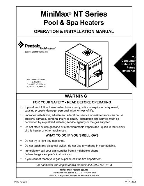
MiniMax ® <strong>NT</strong> <strong>Series</strong>Pool & Spa HeatersOPERATION & INSTALLATION MANUAL11ToConsumerRetain ForFutureReferenceU.S. Patent Numbers6,295,9805,318,007 - 5,228,6185,201,307 - 4,595,825WARNINGFOR YOUR SAFETY - READ BEFORE OPERATING• If you do not follow these instructions exactly, a fire or explosion may result,causing property damage, personal injury or loss of life.• Improper installation, adjustment, alteration, service or maintenance can causeproperty damage, personal injury or death. Installation and service must beperformed by a qualified installer, service agency or the gas supplier.• Do not store or use gasoline or other flammable vapors and liquids in the vicinityof this heater or other appliances.WHAT TO DO IF YOU SMELL GAS• Do not try to light any appliance.• Do not touch any electrical switch; do not use any phone in your building.• Immediately call your gas supplier from a neighbor's phone.Follow the gas supplier's instructions.• If you cannot reach your gas supplier, call the fire department.For additional free copies of this manual; call (800) 831-7133.Pentair Water Pool and Spa, Inc.1620 Hawkins Ave., Sanford, NC 27330 • (919) 566-800010951 W. Los Angeles Ave., Moorpark, CA 93021 • (805) 523-2400Rev. D 12-22-04 P/N 472235
2Customer ServiceIf you have questions about ordering Pentair Pool Products replacement parts, and poolproducts, please use the following contact information.Customer Service (8 A.M. to 5 P.M. Pacific Time)Phone: (800) 831-7133 (press 3 in voice mail)Fax: (800) 284-4151Technical Support for Pentair Pool ProductsWeb siteSanford, North Carolina (8 A.M. to 5 P.M. Eastern Time)Phone: (919) 566-8000Fax: (919) 566-8920Moorpark, California (8 A.M. to 5 P.M. Pacific Time)Phone: (805) 523-2400 (Ext. 6502)Fax: (805) 530-0194visit www.pentairpool.<strong>com</strong> to find information about Pentair Water Pool and Spa, Inc.© 2004 Pentair Water Pool and Spa, Inc.1620 Hawkins Ave., Sanford, NC 27330 • (919) 556-800010951 West Los Angeles Ave., Moorpark, CA 93021 • (805) 523-2400All rights reserved. Information in this document is subject to change without notice.Trademarks and Disclaimers. MiniMax and the Pentair Pool Products logo are registered trademarks of Pentair WaterPool and Spa, Inc. Other trademarks and trade names may be used in this document to refer to either the entities claimingthe marks and names or their products. Pentair Water Pool and Spa, Inc. disclaims any proprietary interest in trademarksand trade names other than its own.P/N 472235 Rev. D 12-22-04
Section I. Heater Identification InformationHeater Identification Information4To identify the heater, see rating plate on the inner front panel of the heater. There are two designators for eachheater, one is the Model Number and the other is the Heater Identification Number (HIN).a. Heater Identification Number (HIN)The following example simplifies the identification system:1) HTR : Heater2) (200, 250, 300 or 400) : Input rating (Btu/hr) X 10003) <strong>NT</strong> : MiniMax <strong>NT</strong> <strong>Series</strong>4) STD or TSI : <strong>Series</strong> Character5) NH or PH: Gas type (Natural gas or Propane gas) and ignition system (Hot Surface Ignition)6) Options :Blank: Standard ModelASME: ASME Certified (Bronze Headers)ASHI: ASME Certified Bronze Header and High Altitude RatingHALT: High Altitude RatingHEATER IDE<strong>NT</strong>IFICATION INFORMATION — (HIN)P/N 472235 Rev. D 12-22-04
Section II.IntroductionIntroductionMiniMax ® <strong>NT</strong> <strong>Series</strong>Pool and Spa Heaters5Congratulations on your purchase of a MiniMax <strong>NT</strong> high performance heating system. Proper installationand service of your new heating system and correct chemical maintenance of the water will ensure yearsof enjoyment. The MiniMax <strong>NT</strong> is a <strong>com</strong>pact, lightweight, efficient, induced-draft, gas fired highperformance pool and spa heater that can be directly connected to schedule 40 PVC pipe. The MiniMax <strong>NT</strong>also <strong>com</strong>es equipped with the Pentair multifunction temperature controller which shows, at a glance,the proper functioning of the heater. All MiniMax <strong>NT</strong> heaters are designed with a direct ignition device,HSI (hot-surface ignition), which eliminates the need for a standing pilot. The MiniMax <strong>NT</strong> requires anexternal power source (120/240 VAC 60 Hz) to operate.This instruction manual provides operating instructions, installation and service information for theMiniMax <strong>NT</strong> high performance heater. The information in this manual applies to all MiniMax <strong>NT</strong> models.It is very important that the owner/installer read and understand the section covering installationinstructions, and recognize the local and state codes before installing the MiniMax <strong>NT</strong>. History andexperience has shown that most heater damage is caused by improper installation practices.IMPORTA<strong>NT</strong> NOTICES...For the installer and operator of the MiniMax <strong>NT</strong> pool and spa heater. The manufacturer’s warranty maybe void if, for any reason, the heater is improperly installed and/or operated. Be sure to follow theinstructions set forth in this manual. If you need any more information, or if you have any questionsregarding to this pool heater, please contact Pentair Water Pool and Spa, Inc. at (800) 831-7133.WARRA<strong>NT</strong>Y INFORMATIO<strong>NT</strong>he MiniMax <strong>NT</strong> pool heater is sold with a limited factory warranty. Specific details are described on thewarranty registration card which is included with the product. Return the warranty registration card afterfilling in the serial number from the rating plate inside the heater.Pentair Pool Products’ high standards of excellence include a policy of continuous product improvementresulting in your state-of-the-art heater. We reserve the right to make improvements which change thespecifications of the heater without incurring an obligation to update the current heater equipment.These heaters are designed for the heating of swimming pools and spas, and should never be used asspace heating boilers, general purpose water heaters, in non-stationary installations, or for theheating of salt water. The manufacturer’s warranty may be void if, for any reason, the heater isimproperly installed and/or operated. Be sure to follow the instructions set forth in this manual.CAUTIONOPERATING THIS HEATER CO<strong>NT</strong>INUOUSLY AT WATER TEMPERATURE BELOW 68° F. WILL CAUSEHARMFUL CONDENSATION AND WILL DAMAGE THE HEATER AND VOID THE WARRA<strong>NT</strong>Y. Do not usethe heater to protect pools or spas from freezing if the final maintenance temperature desired is below68° F., as this will cause condensation related problems.Rev. D 12-22-04 P/N 472235
Section II.Introduction6CODE REQUIREME<strong>NT</strong>SThe installation must conform with local codes or, in the absence of local codes, with the National Fuel GasCode, ANSI Z223.1/NFPA 54 and/or CSA B149.1, Natural Gas and Propane Installation Codes. The heater,when installed, must be electrically grounded and bonded in accordance with local codes or, in the absenceof local codes, in the USA, with the National Electrical Code, ANSI/NFPA 7; in Canada, with CanadianElectric Code, CSA C22.1.CONSUMER INFORMATION AND SAFETYWARNINGThe U.S. Consumer Product Safety Commission warns that elevated water temperature can be hazardous.See below for water temperature guidelines before setting temperature.1. Spa or hot tub water temperatures should never exceed 104° F. A temperature of 100° F. is consideredsafe for a healthy adult. Special caution is suggested for young children. Prolonged immersion in hotwater can induce hyperthermia.2. Drinking of alcoholic beverages before or during spa or hot tub use can cause drowsiness which couldlead to unconsciousness and subsequently result in drowning.3. Pregnant women beware! Soaking in water above 100° F. can cause fetal damage during the first threemonths of pregnancy (resulting in the birth of a brain-damaged or deformed child). Pregnant womenshould stick to the 100° F. maximum rule.4. Before entering the spa or hot tub, the user should check the water temperature with an accuratethermometer. Spa or hot tub thermostats may err in regulating water temperatures by as much as 4° F.5. Persons with a medical history of heart disease, circulatory problems, diabetes or blood pressureproblems should obtain their physician's advice before using spas or hot tubs.6. Persons taking medication which induce drowsiness, such as tranquilizers, antihistamines oranticoagulants should not use spas or hot tubs.WARNINGShould overheating occur or the gas supply fail to shut off, turn off the manual gas control valve to theheater. Do not use this heater if any part has been under water. Immediately call a qualified servicetechnician to inspect the heater and to replace any part of control system and gas control which has beenunder water.P/N 472235 Rev. D 12-22-04
Section III.Installation7Installation InstructionsSPECIFICATIONSThese installation instructions are designed for use by qualified personnel only, trained especially forinstallation of this type of heating equipment and related <strong>com</strong>ponents. Some states require installation andrepair by licensed personnel. If this applies in your state, be sure your contractor bears the appropriatelicense. See Figure 1 for Outdoor and Indoor Installations.24.05HeaterDepthDIMENSIONS IN INCHES3.5014.50MODEL "A" DIM.200 21.63250 24.63300 27.63400 34.13LEG6.648.844.88"A" DIM.OUTDOOR INSTALLATION15.507.352 in. SOCKET30.6324.05LEGINDOOR INSTALLATIONINDOOR VE<strong>NT</strong> ADAPTORP/N 460506P/N 4605074 in. Kit5 in. Kit15.50VE<strong>NT</strong> ADAPTOR(See Indoor VentingInstructions)2.007.352 in. SOCKET24.0530.63Figure 1.LEGRev. D 12-22-04 P/N 472235
Section III.Installation8MANUAL BY-PASSPOOLHEATERMANUALBY-PASSTOPOOLFILTERPUMPWhere the flow rate exceeds the maximum 120 GPM,a manual bypass should be installed and adjusted. Afteradjustments are made, the valve handle should beremoved to avoid tampering. See Figure 2.CHECKVALVEGATEVALVEM odel M in. (GPM)Max. (GPM) *Figure 2.FROMPOOLPLUMBING CONNECTIONSCHECKVALVEThe MiniMax <strong>NT</strong> heater has the unique capability of directschedule 40 PVC plumbing connections. A set of bulkheadfittings is included with the MiniMax <strong>NT</strong> to insureconformity with Pentair’s re<strong>com</strong>mended PVC plumbingprocedure. Other plumbing connections can be used. SeeFigure 2 for plumbing connections.CAUTIONBefore operating the heater on a new installation, turnon the circulation pump and bleed all the air fromthe filter using the air relief valve on top of the filter.Water should flow freely through the heater. Do notoperate the heater unless water in the pool/spa is atthe proper level. If a manual by-pass is installed,temporarily close it to insure that all air is purgedfrom the heater.VALVESWhen any equipment is located below the surface of thepool or spa, valves should be placed in the circulation pipingsystem to isolate the equipment from the pool or spa. Checkvalves are re<strong>com</strong>mended to prevent back siphoning.CAUTIONExercise care when installing chemical feeders soas to not allow back siphoning of chemical into theheater, filters or pump. When chemical feeders areinstalled in the circulation of the piping system,make sure the feeder outlet line is down stream ofthe heater, and is equipped with a positive sealnoncorrosive “Check Valve”, (P/N R172288),between the feeder and heater.20020120250301203003012040040120* Do not exceed the maximum re<strong>com</strong>mendedflow rate for the connecting piping.See page 30 forPressure Relief Valve Installations.BELOW POOL INSTALLATIO<strong>NT</strong>able 1.If the heater is below water level, the pressureswitch must be adjusted. This adjustment must bedone by a qualified service technician.See following CAUTION before installation.CAUTIONBELOW OR ABOVE POOL INSTALLATIO<strong>NT</strong>he water pressure switch is set in the factory at1½ PSI. This setting is for a heater installed at pool levelor within 3’ above or 3’ below. If the heater is to be installedmore that 3’ above or 3’ below, the water pressure switchmust be adjusted by a qualified service technician. Seepage 22, Figure 22.FLOW SWITCHIf the heater is installed more the 6’ above the pool ormore than 10’ below the pool level, you will be beyondthe limits of the pressure switch and a flow switch mustbe installed. Locate and install the flow switch externallyon the outlet piping from the heater, as close as possibleto the heater. Connect the flow switch wires in place ofthe water pressure switch wires.P/N 472235 Rev. D 12-22-04
Section III.Installation9WATER CONNECTIONSReversing Headers —Reversible Inlet/Outlet ConnectionThe MiniMax <strong>NT</strong> <strong>Series</strong> heater is factory assembledwith right side inlet/outlet water connections. Theinlet/outlet header can be reversed for left side waterconnections without removing the heat exchanger.Reversing Water ConnectionsTools required:Phillips Screw Driver9/16 in. Socket and Wrench1/2 in. & 9/16 in. Open Wrench1. Remove the right and left large access doors. It isnot necessary to remove the top of the heater togain access to the headers.NOTEDo NOT remove the high-limit and pressureswitches or the thermistor from the front headerduring the reversing procedure, as they will be inthe proper location when installed on the left side.3. Disconnect the water pressure switch wiring.4. Disconnect the temperature sensor wires fromthe circuit board and feed them back to theheader.2. Disconnect all wires from the high-limitswitches except the short jumper wire.5. Remove the 8 bolts holding the main inlet/outlethead.Rev. D 12-22-04 P/N 472235
Section III.Installation10Reversible Inlet/Outlet Connection,On the MiniMax <strong>NT</strong> <strong>Series</strong> heater there is insulationinstalled by the factory on the return head side of theheaters. This insulation is there so that if the headsare reversed in the field, during initial installation ofthe heater, the high limits will be insulated from theheat radiating from the flue collector.6. Return head in position before removal. This viewshows the insulation installed by the factory.Remove the 8 bolts holding the return head in place.cont’d.9. Install the temperature sensing probe by passingthe wires through the hole provided on the leftside of the brace panel. Route wires through thesupport bracket.7. When heads are removed, replace the heatexchanger tube seal gaskets.10. Reconnect all the high limit wires and thepressure switch wiring, routing the wiresthrough the same hole as the thermostat sensorwires.8. Exchange the inlet/outlet header with the returnheader. Lift the insulation to allow the main headto be installed. Align header with the heatexchanger. When head is placed into position,release the insulation; it will now shield the highlimits from the heat produced by the flue collector.Install header bolts, and tighten snugly by hand.(This will help avoid cross threading.) Whentightening, use a cross pattern starting from thecenter of the header. DO NOT over tighten.11. Pump and bleed system to check the head forleaks.12. Reinstall the two large inspection plates on theappropriate side.Remember: The inlet and outlet markingson the header are still correct.Do not plumb the heater backwards.P/N 472235 Rev. D 12-22-04
Section III.Installation11GAS CONNECTIONSGAS LINE INSTALLATIONSBefore installing the gas line, be sure to check which gas the heater has been designed to burn. This isimportant because different types of gas require different gas pipe sizes. The rating plate on the heater willindicate which gas the heater is designed to burn. The tables, shown on page 12, show which size pipe isrequired for the distance from the gas meter to the heater. The table is for natural gas at a specific gravityof .65 and propane at a specific gravity of 1.55.When sizing gas lines, calculate three (3) additional feet of straight pipe for every elbow used. Wheninstalling the gas line, avoid getting dirt, grease or other foreign material in the pipe as this may causedamage to the gas valve, which may result in heater failure.The gas meter should be checked to make sure that it will supply enough gas to the heater and any otherappliances that may be used on the same meter. The gas line from the meter will usually be of a larger sizethan the gas valve supplied with the heater. Therefore a reduction of the connecting gas pipe will benecessary. Make this reduction as close to the heater as possible.The heater and any other gas appliances must be disconnected from the gas supply piping system during anypressure testing on that system, (greater that ½ PSI). The heater and its gas connection must be leak testedbefore placing the heater in operation. Do not use flame to test the gas line. Use soapy water or anothernonflammable method.NOTEA manual main shut-off valve must be installed externally to the heater.WARNINGDO NOT INSTALL THE GAS LINE UNION INSIDE THE HEATER CABINET. THIS WILL VOID YOUR WARRA<strong>NT</strong>Y.SEDIME<strong>NT</strong> TRAPSInstall a sediment in front ofthe gas controls. The sedimenttrap shall be either a tee fittingwith a capped nipple in thebottom outlet which can beremoved for cleaning, asillustrated in Figure 3, or aother device recognized as aneffective sediment trap. Allgas piping should be testedafter installation in accordancewith local codes.GASSUPPLYMANUALSHUT OFFVALVENIPPLECAPUNIO<strong>NT</strong>EEFITTING3 INCHESMINIMUMGASVALVEHEATER CABINETFigure 3.Rev. D 12-22-04 P/N 472235
Section III.Installation12GAS PIPE SIZINGMODELNATPIPE SIZING FOR GAS LINE CONNECTIONSM AXIMUM EQUIVALE<strong>NT</strong> PIPE LENGTH (Ft.)Natural Gas at 1000 B.T.U. per Cubic FootPropane Gas at 2500 B.T.U. per Cubic Foot“RESIDE<strong>NT</strong>IAL” PROPANE GAS 2 STAGE REGULATIONIn many Propane gas line installations, the gas supplier and/or installer will utilize a two stage regulation processwhere by at the supply tank they will install the first stage gas regulator, which would be at a higher pressure, usually10 psi. This higher pressure allows for a much longer distance and in a much smaller pipe size. Then within a shortdistance of the pool heater, usually around 24 inches, they will install a second regulator, which is the second stage,and this would be set at the required inlet pressure of the heater.See “Gas Pressure Requirement Charts”Table 2.1 /2” 3 /4”1 ” 1 -1/4”1 -1/2”2 ” 2-1/2”PRONATPRONATPRONATPRONATPRONATPRO200- 20’30’80’125’250’450’600’- - - - - -250- 10’20’50’70’150’250’500’600’- - - - -300- - 10’30’50’100’200’350’400’600’- - - -400- - - 10’20’60’100’150’200’450’400’- - -NATPROStage One "High Pressure" Gas Pipe Sizing10 PSI @ 2500 B.T.U. Per CU. FT.MAXIMUM EQUIVALE<strong>NT</strong> PIPELENGTHM odel 0 to 50 Ft.50to 100 Ft.100 to 150 Ft.200through 400 1 /2 in.1 /2 in.1/2 in.Stage Two "Low Pressure" Gas Pipe SizingStage 2 set at 14 in. W.C.MAXIMUM EQUIVALE<strong>NT</strong> PIPE LENGTHM odel 0 to 10 Ft.10 to 20 Ft.200through 400 3 /4 in.3/4 in.Table 3. Table 4.“RESIDE<strong>NT</strong>IAL” NATURAL GAS 2 STAGE REGULATIONIn many Natural gas line installations, the gas supplier and/or installer may utilize a two stage regulation processwhere by at the streets main gas supply they will install the first stage gas regulator, which would be at a higherpressure. This higher pressure is usually set at 2 psi or 5 psi and can be for long distances and in a much smaller pipesize. Then within a short distance of the pool heater, generally around 24 inches, they will install a second regulator,which is the second stage. This second stage regulator would be set at the minimum operating pressure for the heater.For “Natural Gas Pentair Pool Heaters” the minimum is 7 inches W.C.See “Gas Pressure Requirement Charts”Stage One "High Pressure" Gas Pipe Sizing2 PSI @ 1000 B.T.U. Per CU. FT.MAXIMUM EQUIVALE<strong>NT</strong> PIPELENGTHM odel 0 to 50 Ft.50to 100 Ft.100 to 150 Ft.200through 300 1 /2 in.1 /2 in.1/2 in.4003 /4 in.3 /4 in.3/4 in.5 PSI @ 1000 B.T.U. Per CU. FT.200through 400 1 /2 in.1 /2 in.1/2 in.Stage Two "Low Pressure" Gas Pipe SizingStage 2 set at 7 in. W.C.MAXIMUM EQUIVALE<strong>NT</strong> PIPE LENGTHM odel 0 to 10 Ft.10 to 20 Ft.200through 300 3 /4 in.3/4 in.4003 /4 in.1 in.Stage 2 set at 7 in. W.C.200through 400 3 /4 in.1 in.Table 5. Table 6.P/N 472235 Rev. D 12-22-04
Section III.Installation13TESTING GAS PRESSUREInletManifold1. Push the power switch to “OFF”.2. Turn the gas valve knob to “OFF”.3. Remove 1/8 in. NPT plug on the outletside of the valve and screw in theInletManifoldfitting from the Manometer kit.4. Connect the Manometer hose to thefitting.5. Turn the gas valve knob to “ON”.6. Turn on the heater and read theManometer.7. The Manometer must read per thevalues of the Gas PressureRequirement Table, on manifold sideof the gas valve, while operating.MiniMax <strong>NT</strong> TSIMiniMax <strong>NT</strong> STD8. If reading is below specified; check theIllustrations above are for Natural Gas, for Propane requirements, see Table 7.inlet pressure while the heater isrunning to make sure of proper supplybefore attempting adjustments.9. For adjustment, remove the Regulator Adjustment Cap and using a screwdriver turn the screw clockwiseto increase - counterclockwise to decrease gas pressure.CAUTIO<strong>NT</strong>he use of Flexible Connectors (FLEX) is NOT re<strong>com</strong>mended as they cause excessive high gas pressure drops.GAS PRESSURE REQUIREME<strong>NT</strong>SRegulator Adjustment CapGasPressureModelNaturalPropaneInches W.C.1/8" NPT Plug(Inlet Press)Maximum InletSTD1014TSI10N/ AMinimum InletS TD 5*12TSI4 N/ AFigure 4.OFFON1/8" NPT Plug(Manifold Press)ManifoldSTD4 11TSI2 N/ ANOTE:All readings must be taken while heater isoperating. Any adjustments or readings made whileheater is off will result in performance problems.All Values are +/- 0.2 inch W.C.* 6 inch. W.C. for STD 400 Model.Table 7.Rev. D 12-22-04 P/N 472235
Section III.Installation14INDOOR VE<strong>NT</strong>ING — General RequirementsThe vent pipe must be the same size or larger. The MiniMax <strong>NT</strong> heaters are capable of a 360-degree discharge rotationand operate with a positive vent static pressure and with a vent gas temperature less than 400° F. The total length of thehorizontal run must not exceed the length that is listed below in the tables.NOTEThe allowable vent runs for each vent pipe diameter are different and can not be exceeded.Each 90-degree elbow reduces the maximum horizontal vent run by 8 feet and each 45-degree elbow inthe vent run reduces the maximum vent run by 4 feet. See the tables below for the maximum ventlengths using 90-degree and 45-degree elbows.The MiniMax <strong>NT</strong> is a “Category III” appliance and is an induced-draft pool and spa heaterwhich uses positive pressure to push flue gases through the vent pipe to the outside. Thisrequires a <strong>com</strong>pletely sealed vent system—single wall vent pipe with sealed-seams andjoints. Flue gases under positive pressure may escape into the dwelling with any cracksor loose joints in the vent pipe, or improper vent installation. The vent pipe must be of asealed-seam construction, such as those listed for use with “Category III Appliances”, andfor operating temperatures less than 400° F. The use of listed thimbles, roof jacks and/orside vent terminals are required; and the proper clearances to <strong>com</strong>bustible materials mustbe maintained in accordance with type of vent pipe employed—in the absence of a clearancere<strong>com</strong>mendation by the vent pipe manufacturer, the requirements of the Uniform MechanicalCode should be met. The ventilation air requirements for the MiniMax <strong>NT</strong> heater can befound on page 16. It is re<strong>com</strong>mended that vent runs over18 feet be insulated to reduce condensation related problemsand/or the use of a condensate trap in the vent run close to the inch Vent Pipeheater may be necessary in certain installations such as cold Number ofMaximumclimates. The MiniMax <strong>NT</strong> heater is suitable for through-thewallventing, see table and dimensions below.ElbowsVent Run90°5°(Feet)Re<strong>com</strong>mended sources for Side-wall vent hood terminalsinclude: The Field Controls Co. (2308 Airport Road, Kingston,NC 28501, (800)742-8368) and Tjernlund Products Inc. (1601Ninth Street, White Bear Lake, MN 55110, (800) 255-4208)—consult manufacturer for model information and availability.CAUTIONDo NOT <strong>com</strong>bine exhaust vent pipes to a <strong>com</strong>mon exhaustvent in multiple unit installations. Run separate vent pipes.4 inch Vent PipeNumber ofElbows90°45°MaximumVent Run(Feet)1 — 221 1 181 2 142 — 145 5 inch Vent PipeNumber ofElbows4 90°45°Table 8.MaximumVent Run(Feet)0 2 452 2 291 — 452 3 251 1 412 4 211 2 373 — 291 3 333 1 252 — 373 2 212 1 334 — 21Table 9.THROUGH WALL VE<strong>NT</strong> KITS FOR HEATERSCFPartNumberDim.ADim.BDim.CDim.DDim.EDim. FBAE4715324 in. Dia.6 in. Dia.8 ½ in.6 5/16 in.125/8 in.10 5/8 in.4715435 in. Dia.8 in. Dia.8 ½ in.8 in.125/8 in.10 5/8 in.DTable 10. Figure 5.P/N 472235 Rev. D 12-22-04
Section III.Installation15INDOOR INSTALLATION (USA ONLY)OUTDOOR SHELTER INSTALLATION (CANADA)See page 16 for Vent AdaptorsAll products of <strong>com</strong>bustion and vent gases must be<strong>com</strong>pletely removed to the outside atmosphere through avent pipe which is connected to the stack adaptor. A ventpipe extension of the same size must be connected to thevent adaptor and extended at least 2 feet higher than highestpoint of the roof within a 10 foot horizontal radius, and atleast 3 ft. higher than the point at which it passes throughthe roof, or as permitted by local code; see Figures 6, 7and 12. The vent should terminate with an approved ventcap (weather cap) for protection against rain or blockageby snow. Insulated vent pipe and an approved roof jackshall be employed through the roof penetration.The heater must be located as close as practical to achimney or gas vent.CAUTIO<strong>NT</strong>he heater should be installed at least 5 feet awayfrom the pool or spa.The heater must be placed in a suitable room with adequateventilation and on a leveled floor, where leakage from heatexchanger or water connections will not result in damageto the area adjacent to the heater or the structure. Whensuch locations cannot be avoided, it is re<strong>com</strong>mended thata suitable drain pan with adequate drainage, be installedunder the heater. The pan must not restrict air flow.It is re<strong>com</strong>mended to install the heater on fire-resistanceslabs. Do not install the heater directly on a <strong>com</strong>bustiblewood floor without placing a non-<strong>com</strong>bustible materialbetween the floor and the heater. Heaters must NEVERbe installed directly on carpeting.Installations in basements, garages, or undergroundstructures where flammable liquids may be stored musthave the heater elevated 18 inches from the floor. Thefollowing minimum clearances from <strong>com</strong>bustible materialsmust be provided.Vent Cap andRiser Furnishedby InstallerOptionalSideWall VentVent Cap andRiser Furnishedby InstallerOptionalSideWall VentHeaterHeaterChimney or Gas VentChimney or Gas VentOutlet AirOpeningInlet AirOpeningOutlet Air OpeningInlet Air OpeningFigure 7.The heater should not be installed closer than 6 inches toany fences, walls or shrubs at any side or back, norcloser than 18 inches at the plumbing side. A minimumclearance of 24 inches must be maintained at the front ofthe heater.6"Figure 6.SIDEOFHEATERINDOOR(Outrdoor Shelter)INCHESINSTALLATIONOUTDOORINCHES24"DOOR6"WATER PIPING 1818BLANK6 6REAR6 6TOP *18Open Un-roofed Area18"FRO<strong>NT</strong>2424* To ceiling or roof.Table 11.Figure 8.Rev. D 12-22-04 P/N 472235
Section III.Installation16COMBUSTION AIR SUPPLYFor indoor installation, the heater location mustprovide sufficient air supply for proper <strong>com</strong>bustionand ventilation of the surrounding area.The requirements for the air supply specify that theroom in which a heater is installed should be providedwith two permanent air supply openings; one within12 inches of the ceiling, the other within 12 inches ofthe floor. These openings shall directly, or throughduct, connect to outdoor air.Pentair Water Pool and Spa, Inc. does not re<strong>com</strong>mendindoor installations that do not provide <strong>com</strong>bustionair from outside the building.CAUTIONAir Supply Requirements Guidefor MiniMax <strong>NT</strong> HeatersNet Free open Area forEach Opening * (Square Inches)HeaterSizeDucted fromOutsideDirect fromOutside200100502501256330015075400200100* Area indicated is for one of two openings; one at floorlevel and one at the ceiling.N OTE: If using louvered type or screen type openings,check with Louver/Screen Manufacturers to correct forthe Louver/Screen resistance.Table 12.Chemicals should not be stored near the heater installation. Combustion air can be contaminated by corrosivechemical fumes which can void the warranty.VE<strong>NT</strong> ADAPTORS(FITS ALL MODELS)The proper vent adaptor must be installed on the heateras shown below in Figure 9.1. Remove the six (6) retaining screws from the oldexhaust grill and discard the screws, gasket, andexhaust grill as shown in Figure 10.GASKETEXHAUST GRILLSCREWS (6)P roduct No. Vent Dia.4605064 in.4605075 in.VentAdaptorFigure 10.2. Install the Vent Adaptor as shown in Figure 11.Make sure the holes in the gasket, metal flange ofthe main vent assembly, and heater cover arealigned before securing into place using the six (6)screws provided in the Vent Adaptor Kit.METAL FLANGEGASKETSCREWS (6)Figure 9.Figure 11.P/N 472235 Rev. D 12-22-04
Section III.Installation17INDOOR INSTALLATIONSMINIMAX <strong>NT</strong> VE<strong>NT</strong>ING GUIDELINES4'Vent Hood4'1' min.1' min.vent terminated at least 24"above any object within 10 ft.More Than10 ft.Ridge2 ft. min.Vent Cap3 ft. min.RoofJackRoofThimbleChimney/Gas VentVent for roof penetration installations:must extend at least 3 ft. higher than thepoint at which it passes through the roof,or as permitted by local code.must use a roof thimble through theroof penetration.must terminate with an approved (listed)roof jack, storm collar, and vent/weather cap.Vent pipe extension:must be the same diameter as thevent connector.must be suitable for use with category IIIappliances with flue gas temperature ratingsless than 400 deg. F.may use a single wall vent pipe withpermanently sealed seams, joints andproper insulating materials.Vent Hood3'7'Force Air Inlet4'Vent Hood1' min.above gradeWalkwayVent termination for side wall installations:Re<strong>com</strong>mended sources forside wall Vent Hood;see "Section Venting".must be not less than 7 ft. above public walkways.must be at least 3 ft. above any outside air intake located within a 10 ft. radius.must NOT be within 3 ft. of an inside corner of the structure.must be at least 1 ft. above grade.must be located the following distances away from any door, window, or gravity air inlet:4 ft. below4 ft. horizontally1 ft. aboveAir SupplyClearances indicated are for non-mechanical air supply inlet to the building.For mechanical air supply inlet, a minimum horizontal clearance of 10 feetshould be maintained away from the vent termination.Figure 12.Rev. D 12-22-04 P/N 472235
Section III.Installation18OUTDOOR INSTALLATION(Outdoor Shelter Installation in Canada, see page 15)For outdoor installation with an exhaust grill, the heater must be placed in a suitable area on a level, non<strong>com</strong>bustible surface. Do notinstall the heater under an overhang with clearances less than 3 feet from the top of the heater. The area under an overhang must beopen on three sides.IMPORTA<strong>NT</strong>!• In an outdoor installation it is important to ensure water is diverted from overhanging eves with a propergutter/drainage system. The heater must be set on a level foundation for proper drainage.• Under certain conditions, “heavy rains or unusually high winds”, it may be necessary to install an outdoorsvent. In this situation, use Outdoor Vent Kit, P/N 460424, (see below).• This unit shall not be operated outdoors at temperatures below -20 o F.OUTDOOR INSTALLATIONVE<strong>NT</strong>ING GUIDELINESSIDE VIEW3'4'4'Property LineWindow4 ft.4 ft.Exhaust Grill(Vent)4'ForceAir InletCheck local building codesfor setback requirements.BuildingHeater(side view)OUTDOOR VE<strong>NT</strong> KITFigure 13.Vent Termination:Must be at least 3 ft. above any forcedair inlet located within a 10 ft. radius.Must be located 4 feet away from the building wallopenings, and at the following distances away fromany door, window, or gravity air inlet:4 ft. below,4 ft. horizontally1. Remove the six (6) retaining screws from the old exhaust grill and discard the screws, gasket, and exhaust grill as shown in Figure 14.2. Install the Outdoor Vent Kit, (P/N 460424), as shown in Figure 15. Make sure the holes in the gasket, metal flange of the main ventassembly, and heater cover are aligned before securing into place using the six (6) screws provided in the Outdoor Vent Kit.GASKETEXHAUST GRILLSCREWS (6)GASKETMETAL FLANGESCREWS (6)Figure 14. Figure 15.CAUTIONIf installing the heater next to or near an air conditioning unit or a heat pump, allow a minimum of 36 in.between the air conditioning unit and the heater.P/N 472235 Rev. D 12-22-04
Section III.Installation19ELECTRICAL CONNECTIONSElectrical Rating 60 Hz 120 / 240 Volts AC, single phaseCAUTIO<strong>NT</strong>his heater is designed to operate at 120 or 240 VAC. It is not re<strong>com</strong>mended to be connected to OR operate on a 208 VAC.NOTE• The MiniMax <strong>NT</strong> heater is prewired for 240-volt AC connection using the “RED” connector and the “BEIGE” <strong>com</strong>mon connector;see Figure 16 below. For 120-volt AC supply, remove the “BEIGE” <strong>com</strong>mon connector and plug it into the “BLUE” <strong>com</strong>monconnector.• When connecting the power supply to the “Line Terminal Block” inside the junction box, follow the polarity as shown below.Connecting to 120 VAC, make sure that you connect the wire to the terminal (L), the neutral wire is connected to the neutralterminal (N) and the ground is connected to the ground terminal (GND); see below, Figure 17.• If any of the original wiring supplied with this heater must be replaced, installer must supply (No. 18 AWG, 600V, 105° C.U.L. approved AWM low energy stranded) copper wire or it’s equivalent. Thermal fuse wiring must be replaced with 18 AWG,600V, 150° C. temp. rating.CAUTIO<strong>NT</strong>he installation must conform with local codes or, in the absence of local codes, with the National Fuel Gas Code,ANSI Z223.1/NFPA 54 and/or CSA B149.1, Natural Gas and Propane Installation Codes. If an external electricalsource is utilized, the heater, when installed, must be electrically grounded and bonded in accordance with localcodes or, in the absence of local codes, in the USA, with the National Electrical Code, ANSI/NFPA 7; in Canada, withCanadian Electric Code, CSA C22.1.Always use crimp type connectors when connecting two wires.TRANSFORMERCONNECTORBLUE120V CONNECTORFigure 16.BEIGECOMMON CONNECTORRED240V CONNECTORGREEN WIRELINE TERMINAL BLOCKTERMINAL BLOCKFOR AC INPUT120 / 240 VOLT SINGLEPHASE "See Below"GROUNDCONNECTIONYou need to open the rightdoor then remove thecontrol panel cover forservicing the Line TerminalBlock as shown in Figures16 & 17, (see item 40 in theexploded view on page 33).I<strong>NT</strong>ERNALFACTORY WIRESWHITE WIRENNEUTRAL / WHITE 120 VACLINE #1 FOR 240 VACBLACK WIRELHOT / BLACK 120 VACLINE #2 FOR 240 VACFigure 17.Rev. D 12-22-04 P/N 472235
Section III.Installation20WIRING DIAGRAM–<strong>NT</strong> STD & TSI WITH DDTCGYNOTE :THE HEATERIS PREWIREDFOR 240 VACOPRBRBKR/WYRBKJ12BK/W4P12(240V)GYBKYGYGYGYBKBKWP12(120V)28945671231234567567898913GYBKBKBLBKBKBKWGYBKBKWWWWBKBKJ13W1 12 23 345 5P134WWWBKBKBK 6 6 BKY WBKOPRBRBRBRIGNITERFLAME SENSORJ14P14BLOWERBLBKYBRRGYOPRWJ17IGN/120L1IGN/240L2IGN/FSPSTH24VACVLVGNDF1F2FCJ16WWSI L'INSTALLATION ELECTRIQUE ORIGINALE D'USINE DOIT ETRE REMPLACEE,L'INSTLLATEUR DOIT PROCURER DES CABLES UL/CSA APPROUVES AVEC18 AWG, 600V, 105 DEGRES CELSIUS D'ECHELLE DE TEMPERATURE.L'INSTALLATION ELECTRIQUE DU FUSIBLE THERMIQUE DOIT ETRE REMPLACEEAVEC UNE ECHELLE DE TEMPERATURE A 18 AWG, 600V, 150 DEGRES CELSIUS.BRWBKTERMW N BLOCKG G120 VACW ORBK L 240 VACBKBOND LOG(ON THE SIDE JACKET)GMiniMax <strong>NT</strong> TSI & STD W/DDTC Wiring DiagramRHIGH LIMITS115˚FORTHERMAL FUSEYPRPR150˚FJ15 P15GAS VALVEGWATER PRESSSWITCHMVMVRWBLWOATTACHGROUNDWIRE HEREWIRE COLOR(COULEUR DU CABLE)BK : BLACK (NOIR)BL : BLUE (BLEU)BR : BROWN (MARRON)G : GREEN (VERT)GY : GRAY (GRIS)O : ORANGE (ORANGÉ)PR : PURPLE (VIOLET)R : RED (ROUGE)Y : YELLOW (JAUNE)W : WHITE (BLANC)R/W : RED W/WHITE TRACE(ROUGE ET/BLANC)BK/W : BLACK W/WHITE TRACE(NOIR ET/BLANC)PROBKWYRRR/WBK/WR/WBK/WBKBKGYPRWSEE OPERATIONR& INSTALLATIONOMANUAL FORPRPRRRYYREMOTE CO<strong>NT</strong>ROLP11P10P7P4{GYCOM NOJ2J5 J8 J6 J1J11IGNJI0VLVMODP9J4 J724V TFUSEHLMTPRESSFAN24VACSPACOMPOOLAIR PRESSURE SW.O OBLOWERJ9THERMISTERDDTCIF ORIGINAL FACTORY WIRING MUST BE REPLACED,INSTALLER MUST SUPPLY UL/CSA APPROVED WIREWITH 18 AWG, 600V, 105˚C TEMP. RATING.THERMAL FUSE WIRING MUST BE REPLACED WITH18 AWG, 600V, 150˚C TEMP. RATING.472153DFigure 19.P/N 472235 Rev. D 12-22-04
Section IV.Operation21Operation InstructionBASIC SYSTEM OPERATION1. Start pump, make sure the pump is running and is primed, to close the water pressure switch and supply power toheater. Be sure the pool and/or spa is properly filled with water. Follow the Lighting/Operating instructions below.MINIMAX <strong>NT</strong> HSI ELECTRONIC IGNITION LIGHTING/OPERATIONFOR YOUR SAFETY: READ BEFORE LIGHTINGIf you do not follow these instructions exactly, a fire or explosion may result causing property damage, personalinjury or loss of life.Do not attempt to light the heater if you suspect a gas leak. Lighting the heater can result in a fire or explosionwhich can cause personal injury, death, and property damage.A. This appliance does not have a pilot. It is equipped withan ignition device which automatically lights the burners.Do not try to light the burners by hand.B. BEFORE OPERATING, smell all around the appliancearea for gas. Be sure to smell next to the floor because somegas is heavier than air and will settle on the floor.WHAT TO DO IF YOU SMELL GAS- Do not try to light any appliance.- Do not touch any electrical switch; do not use any phone inyour building.- Immediately call your gas supplier from a neighbor's phone.Follow the gas supplier's instructions.1. STOP! Read the safety information above, (A through D).2. Open the access doors. Set power switch to ”OFF”, (seeFigure 25).3. Set the thermostat to ”OFF”, (see page 27).4. This appliance is equipped with an ignition device whichautomatically lights the burners. Do not try to light the burnersby hand.5. Push in gas control knob slightly and turn clockwiseto “OFF”.NOTE: Knob cannot be turned to “OFF” unless knob ispushed in slightly. Do not force.6. Wait five (5) minutes to clear out any gas. If you then smellgas, STOP! Follow "B" in the safety information above.If you don't smell gas, go to the next step.7. Turn gas control knob counterclockwise to “ON”.See Figure 20.8. Close the access doors and set the thermostat to desiredMode: “POOL, SPA or REMOTE”.1. Turn off all electric power to the appliance if service is tobe performed.2. Set the thermostat to “OFF”.WARNINGOPERATING INSTRUCTIONS- If you cannot reach your gas supplier, call the FireDepartment.C. Use only your hand to push in or turn the gas control knob.Never use tools. If the knob will not push in or turn by hand,don't try to repair it, call a qualified service technician. Forcedor attempted repair may result in a fire or explosion.D. Do not use this appliance if any part has been under water.Immediately call a qualified service technician to inspectthe appliance and to replace any part of the control systemand any gas control which has been under water.9. Set the thermostat to the desired temperature setting.a. Ignition module is energized and the pre-purge cycle isstarted, approximately 15 seconds.b. Fan motor starts, which closes Vacuum Air Pressure (fan)switch.c. Check for powering-up the (glow coil) hot-surface ignitorby viewing through the glass window or opening on theburner face plate.10. If the appliance will not operate, follow the instructions"To Turn Off Gas To Appliance" and call your service technicianor gas supplier.Figure 20.Gas control knob shown in “ON” position.Rev. D 12-22-04 P/N 472235GasInletTO TURN OFF GAS TO APPLIANCE3. Open access doors.4. Push in gas control knob slightly and turn clockwiseto "OFF". Do not force.5. Close access doors.OFFON
Section IV.Operation22SAFETY CO<strong>NT</strong>ROLSVACUUM AIR PRESSURE (FAN)SWITCHFigure 21.The air pressure switch, (see Figure 21), is a safetydevice used to insure that the <strong>com</strong>bustion air blower(fan) is operating and has been designed to monitorthe vacuum (negative) pressure within the blowerhousing. The air pressures switch is factory set and isconnected upstream of the ignition module. Theignition module does not operate unless the airpressure switch and all safety switches are closed.AIR PRESSURE SWITCHWATER PRESSURE SWITCHThe water pressure switch, (see Figure 22), closeswhen there is a sufficient flow of water to the heatexchanger to safely operate the heater. The switch hasbeen preset by the Factory at 1½ PSI for operation.NOTE: See, Below Pool Level Installationinstructions on page 8. The switch may remain closedwith no water flow if there is more than a 3 ft. elevationdifference between the heater (heat exchanger) andthe pool water line—if this is the case, the waterpressure switch must be reset by a qualified servicetechnician to maintain open switch contacts with nowater flow.NOTEIf the pool is more than one floor above or one floorbelow the heater, the water pressure switch mayhave to be replaced with a flow switch.Air Pressure SwitchFigure 22.Adjustment KnobTypical Water Pressure SwitchTHERMAL FUSEThis is a single-use switch, mounted on <strong>com</strong>bustionchamber jacket divider (inner front panel). The fuse,(see Figure 23), is activated by excessive temperaturedue to abnormal operating conditions. Upon detectionof excessive heat within the inner front panel, the fusewill open the safety circuit causing shutdown of theheater.Thermal FuseFigure 23.P/N 472235 Rev. D 12-22-04
Section IV.Operation24DIGITAL DISPLAY TEMPERATURE CO<strong>NT</strong>ROLLER (DDTC)REMOTE BUTTONPOWERPRESSURE SWREMOTEPOOLPOOL BUTTONSYSTEMINDICATORLIGHTSTHERMOSTATHEATINGSPAOFFTEMPERATURE SETTINGSPA BUTTONOFF BUTTONSERVICEPOOLSPATEMP. UPFigure 26.PRESS ANY ARROW ONCE TOCHECK SET TEMPERATURESPA AND POOLTEMPERATURESET BUTTONSTEMP. DOW<strong>NT</strong>he DDTC board, shown in Figure 26, is a digital temperature controller capable of controlling the pool, spaor both to a minimum temperature of 65° F. (below 65° F. display reads "Off") and a maximum of 104° F.The DDTC board also functions as a system status indicator, using LED lights and programmed error codes.During normal operation, the DDTC will display the current temperature of the water returning to theheater, depending on which mode has been selected, “Pool” or “Spa”. This is ac<strong>com</strong>plished by a thermister(sensor) on the inlet port of the water header of the heater and working in conjunction with the internalmicroprocessor controlling the operation of the heater.Changing the desired pool or spa temperature is easily done by simply depressing the appropriate up ordown arrow until the display reads the desired set-point temperature. For example, set pool to 78° F. and thespa to 104° F., when releasing the up or down arrow the display will flash once then return to the currenttemperature.At any time, you wish to know the temperature setting of the pool or spa, simply press the appropriate up ordown arrow, the display will flash once and display the set-point temperature for three (3) seconds, thenflash once again and return to the current temperature.P/N 472235 Rev. D 12-22-04
Section IV.Operation25Figure 27.Rev. D 12-22-04 P/N 472235
Section IV.Operation27• HEATINGThe heating light is on any time the thermostat has signaled a call for heat which initializes the ignitionsafety circuit — the light <strong>com</strong>es on indicating successful firing of the main burners and stays on until thepool/spa reach the water temperature setting.• SERVICEThe service light is off during normal operation of heater. The light only <strong>com</strong>es on if a problem with acontrol has occurred or when the heater is first firing. The problem must be investigated by the technicianprior to attempts to fire the heater again.TEMPERATURE SETTINGThe heater <strong>com</strong>es factory set at 78° F. for the pool mode and 100° F. for the spa mode, using the up anddown arrows, you can set the thermostats to a minimum temperature of 65° F., or a maximum of 104° F. Ifyou desire to heat only one body of water, the thermostat is capable of an off mode. As an example, if youonly wish to heat the spa and not the pool, simple depress and hold the pool down arrow, and the thermostatwill lower its setting to 65° F. then go to an off mode. If there is a remote system connected to the heater,please see the special thermostat setting features under Heating Mode Selection & Remote mode.HEATING MODE SELECTION1. Off Mode: The heater will not <strong>com</strong>e on. NOTE: The "Off" display on the Digital Display TemperatureController does not mean that the heater is off. It only states that the pool or spa thermostat has beenturned off.2. Spa Mode: The heater will operate and heat the spa to the desired temperature.3. Pool Mode: The heater will operate and heat the pool to the desired temperature.4. Remote Mode: The DDTC is <strong>com</strong>patible with two and three wire remote control systems. In order tooperate by a remote control system, the REMOTE mode must be selected on the front panel. When theREMOTE mode is selected, the REMOTE LED will light up.REMOTE CO<strong>NT</strong>ROLTHE TWO-WIRE REMOTE CO<strong>NT</strong>ROL SYSTEM is typically installed and connected to the heater for spaheating. The two-wire remote system is usually provided with a water temperature sensor that monitors thesystem temperature and turns the heater on or off in response to the temperature of the spa. To heat a spa, itshould be connected to terminals J6 and J8. Pool heating remote control would require connecting toterminals J5 and J8. If the REMOTE mode is set at the front panel LED light, the DDTC will respond to acontact closure by remote system and heater will operate until the remote system temperature setting issatisfied.NOTE: With this type of two-wire remote, with its own temperature sensors and system control, using theup arrows on the front of the DDTC, hold down the up arrow until you reach the maximum setting of104° F., this allows the remote system thermostat to operate the heater at any set-point below 104° F., theheater thermostats then act as a secondary controller if water temperature reaches 104° F.THE THREE-WIRE REMOTE CO<strong>NT</strong>ROL SYSTEM will be connected to terminals J5, J6 & J8. J8 is the<strong>com</strong>mon terminal. If the heater is in the REMOTE mode, the DDTC will monitor the terminals and respondto a contact closure between J5 & J8 or J6 & J8. A contact closure between J5 & J8 will cause the DDTC toswitch to the POOL setting and control the heater to the DDTC pool set-point temperature. A contactclosure between J6 & J8 will cause the DDTC to switch to the SPA setting and control the heater to theDDTC spa set-point temperature. If only heating the spa, then depress the pool down arrow until the displaygoes to “Off”.Rev. D 12-22-04 P/N 472235
Section V.TroubleshootingTroubleshooting Instruction28TROUBLESHOOTING (DDTC)The DDTC temperature display contains three LED’s with a decimal point between the first and second, thisdisplay is also used to display an error code if for some reason there is a failure within the heater controlsystem or a DDTC internal fault. The DDTC will display the actual temperature or set-point temperature orOFF, as selected by the user. When DDTC detects an error, the display will show Exx, see Figure 27, whereExx is the error code of DDTC fault, see Table 13. Codes 1 through 9 indicate a “soft lockout” error thatmeans after these errors are fixed, the heater will resume normal operation and restart immediately. CodeERR indicates a “hard lockout” error that means after these errors are fixed, you need to reset the power ofthe heater through the switch on the bottom of the electrical junction box on the right side of the cabinet.NOTE: If Code ERR is shown on the LED display at any time, turn the heater off, (from power switch),then turn on the heater again. If the error code is still displayed, call a certified Pentair Service Technicianfor repair.ErrorE01E02E03E04E05E06CodeError Descriptio nSystem Low Voltag eHigh Temperature LimitThermal Fuse OpenFan FailureIgnition / Flame FailureGas Valve / Module FailureE07,E08, E09Not UsedERRCall Pentair's Technical Service Department at: (800) 831-7133Table 13.P/N 472235 Rev. D 12-22-04
Section V.Troubleshooting29TROUBLESHOOTING (GENERAL)Possible CauseRemedyHeater will not <strong>com</strong>e onCheck if electrical connections areAutomatic ignition system fails correct and securely fastened –If YES, call serviceperson.Pump not runningPlace pump in operationPump air lockedCheck for leaksFilter dirtyClean filterPump strainer cloggedClean strainerDefective wiring or connectionRepair or replace wiresDefective pressure switchReplace switchDefective gas controlsCall servicepersonOn-Off switch in "OFF" positionTurn switch to "ON"Heater Short Cycling (Rapid On and Off Operation)Insufficient water flowClean filter and pump strainerDefective wiringRepair or replace wiringDefective flow valve or out of adjustment Call servicepersonDefective hi-limit and/or thermostatCall servicepersonHeater Makes Knocking Noises,make sure all valves on system are open.Heater operating after pump has shut off Shut off gas supply and call servicepersonHeater exchanger scaledShut off gas supply and call servicepersonSERVICE CHECKS—IGNITION MODULESymptomCause/Cure1.DeadA. MiswiredB. Transformer badC. Fuse/Circuit breaker badD. Bad control2.Thermostat on—no ignition A. MiswiredB. Bad thermostat no voltage at terminal3.Valve on, no ignition A. Defective ignitorB. MiswiredC. Bad control (check voltage at ignitor)4.Ignitor on, no valve action A. Valve coil openB. Open valve wireC. Bad control (check voltage)5. Flame okay duringTry For Ignition (TFI),no flame sense (after TFI)A. Bad flame sensorB. Bad wiresC. Poor ground at burnerD. Poor flame (check flame current)Rev. D 12-22-04 P/N 472235
Section VI.MaintenanceMaintenance InstructionIt is re<strong>com</strong>mended that you check the following items atleast every six months and at the beginning of everyswimming season.1. Examine the venting system. Make sure there are noobstructions in the flow of <strong>com</strong>bustion andventilation air.2. Visually inspect the main burner and the hot surfaceignitor. The normal color of the flame is blue. Whenflame appears yellow, burners should be inspectedand cleaned. Check ignitor for damage.3. Inspect the heat exchanger for soot. Clean asnecessary.4. Remove burner tray and clean burners and mainburner orifices.5. Keep the heater area clean and free from<strong>com</strong>bustibles and flammable liquids.6. Check wire ends and wire connections. They shouldbe clean and tight.7. Check the gas pressure (supply and manifold) asdescribed in this manual.STANDARD STDFigure 28.TSI TSIPRESSURE RELIEF VALVEIn some installations, a pressure relief valve (PRV)is required on the MiniMax <strong>NT</strong> <strong>Series</strong>. To install a PRV,remove the accessdoors, removeFlow Valveassembly, thencarefully drill a3/8 in. hole incenter of 3/4 in.NPT port (on mainheader) beingcareful to drill onlythrough wall atbottom of 3/4 in.NPT port and nodeeper—now thread inthe 3/4 in. NPT PRV.NOTE: (A.S.M.E.version varies slightly.It is of bronzeconstruction, and issupplied with theA.S.M.E. Section IV,pressure relief valvepre-installed atfactory.)Test the relief valveat least once a yearby lifting up lever.CAUTIONREMOVE THE FLOW VALVE ASSEMBLY WHEN DRILLINGTHE HOLE TO INSTALL A PRV, OTHERWISE, YOU WILLDRILL I<strong>NT</strong>O THE VALVE ASSEMBLY.REMOVE FLOW VALVEBEFORE DRILLINGTHE NPT PORTA.S.M.E. VERSIONA.S.M.E. VERSIONFigure 29.30RELIEFVALVEFOR PRVINSTALLATIONDRILL THRUTHE NPT PORTRELIEF VALVETO WI<strong>NT</strong>ERIZE,OPEN DRAIN VALVEENERGY SAVING TIPS1. If possible, keep pool or spa covered when not inuse. This will not only cut heating costs, but alsokeep dirt and debris from settling in the pool andconserve chemicals.2. Reduce the pool thermostat setting to 78° F. orlower. This is accepted as being the most healthytemperature for swimming by the American RedCross.3. Use an accurate thermometer.4. When the proper maximum thermostat settingshave been determined, tighten the thermostat knobstopper.5. Set time clock to start circulation system no earlierthan daybreak. The swimming pool loses less heatat this time.6. For pools that are only used on the weekends, it isnot necessary to leave the thermostat set at 78° F.Lower the temperature to a range that can beachieved easily in one day. Generally, this wouldbe 10° F. to 15° F., if pool heater is sized properly.7. During the winter or while on vacation, turn theheater off.8. Set up a regular program of preventativemaintenance for the heater each new swimmingseason. Check heat exchanger, controls, burners,operation, etc.P/N 472235 Rev. D 12-22-04
Section VI.Maintenance31SPRING AND FALL OPERATIONIf the pool is being used occasionally, do not turn the heater <strong>com</strong>pletely off. Set the thermostat down to65° F. This will keep the pool and the surrounding ground warm enough to bring the pool up to a<strong>com</strong>fortable swimming temperature in a shorter period of time.WI<strong>NT</strong>ER OPERATIONCAUTION• Operating this heater continuously at water temperatures below 68° F. will cause harmful condensation and willdamage the heater and void the warranty.• If the heater has been drained for freezing condition, do NOT turn "ON" until the system is circulating water.• Water trapped in the heat exchanger can result in freeze damage to the exchanger or headers. Freeze damage isspecifically not covered by the warranty.If the pool won't be used for a month or more, turn the heater off at the main gas valve. For areas wherethere is no danger of water freezing, water should circulate through the heater all year long, even though you arenot heating your swimming pool. The MiniMax <strong>NT</strong> should not be operated outdoors at temperaturesbelow 0° F. for propane and -20° F. for natural gas. Where freezing is possible, it is necessary to drainthe water from the heater. This may be done by opening the drain valve, located at the inlet/outlet header,(see Figure 29.), allowing all water to drain out of the heater. It would be a good practice to use <strong>com</strong>pressedair to blow the water out of the heat exchanger. (See additional notes under Important Notices inIntroduction.)Rev. D 12-22-04 P/N 472235
Section VI.MaintenanceCHEMICAL BALANCEPOOL AND SPA WATERYour Pentair Pool Products pool heater was designedspecifically for your spa or pool and will give you manyyears of trouble-free service, provided you keep yourwater chemistry in proper condition.Three major items that can cause problems with yourpool heater are: improper pH, disinfectant residual, andtotal alkalinity. These items, if not kept properlybalanced, can shorten the life of the heater and causepermanent damage.CAUTIONHeat exchanger damage resulting from chemicalimbalance is not covered by the warranty.WHAT A DISINFECTA<strong>NT</strong> DOESTwo pool guests you do not want are algae and bacteria.To get rid of them and make pool water sanitary forswimming - as well as to improve the water's taste, odorand clarity - some sort of disinfectant must be used.Chlorine and bromine are universally approved by healthauthorities and are accepted disinfecting agents forbacteria control.WHAT IS A DISINFECTA<strong>NT</strong>RESIDUAL?When you add chlorine or bromine to the pool water, aportion of the disinfectant will be consumed in theprocess of destroying bacteria, algae and other oxidizablematerials. The disinfectant remaining is called chlorineresidual or bromine residual. You can determine thedisinfectant residual of your pool water with a reliable testkit, available from your local pool supply store.You must maintain a disinfectant residual level adequateenough to assure a continuous kill of bacteria or virusintroduced into pool water by swimmers, through the air,from dust, rain or other sources.It is wise to test pool water regularly. Never allowchlorine residual to drop below 0.6 ppm (parts permillion). The minimum level for effective chlorine orbromine residual is 1.4 ppm.pH - The term pH refers to the acid/alkaline balance ofwater expressed on a numerical scale from 0 to 14. A testkit for measuring pH balance of your pool water isavailable from your local pool supply store; see Table 14.pH ChartTable 14.Strongly Acid Neutral Strongly Alkaline0 1 2 3 4 5 6 7 8 9 10 11 12 13 14Muriatic Acid has a pH of about 0. Pure water is 7(neutral). Weak Lye solution have a pH of 13-14.RULE: 7.4 to 7.6 is a desirable pH range. It is essentialto maintain correct pH, see Table 15.If pH be<strong>com</strong>es too high (over alkaline), ithas these effects:1. Greatly lowers the ability of chlorine to destroybacteria and algae.2. Water be<strong>com</strong>es cloudy.3. There is more danger of scale formation on theplaster or in the heat exchanger tubing.4. Filter elements may be<strong>com</strong>e blocked.If pH is too low (over acid) the followingconditions may occur:1. Excessive eye burn or skin irritation.2. Etching of the plaster.3. Corrosion of metal fixtures in the filtration andrecirculation system, which may create brown, blue,green, or sometimes almost black stains on theplaster.4. Corrosion of copper tubes in the heater, which maycause leaks.5. If you have a sand and gravel filter, the alum used asa filter aid may dissolve and pass through the filter.CAUTION: Do not test for pH when the chlorineresidual is 3.0 ppm or higher, or bromine residualis 6.0 ppm or higher. See your local pool supplystore for help in properly balancing your waterchemistry.RULE: Chemicals that are acid lower pH. Chemicalsthat are alkaline raise pH.Table 15.6.8 7.0 7.2 7.4 7.6 7.8 8.0 8.2 8.4Add Soda, Ash orSodium BicarbonatepH Control ChartMarginalIdealMarginalALKALINITY High or Low:"Total alkalinity" is a measurement of the total amountof alkaline chemicals in the water, and control pH to agreat degree. (It is not the same as pH which refersmerely to the relative alkalinity/acidity balance.) Yourpool water's total alkalinity should be 100 - 140 ppm topermit easier pH control.A total alkalinity test is simple to perform with a reliabletest kit. You will need to test about once a week andmake proper adjustments until alkalinity is in the properrange. Then, test only once every month or so to be sureit is being maintained. See your local pool dealer forhelp in properly balancing the water chemistry.32Add AcidP/N 472235 Rev. D 12-22-04
33REPLACEME<strong>NT</strong> PARTS<strong>NT</strong> STD w/DDTC — (all Models)<strong>NT</strong> TSI w/DDTC — (200, 250, and 300 Models)293036313334 35FOR STDONLYFOR TSIONLYRev. D 12-22-04 P/N 472235
34P/N 472235 Rev. D 12-22-04
✭ 35✭ReplacementParts for the400 Model <strong>Series</strong>are for modelsmanufacturedprior to productSerial No.12040039Rev. D 12-22-04 P/N 472235
36REPLACEME<strong>NT</strong> PARTS<strong>NT</strong> TSI w/DDTC — (400 Model — Starting w/Serial No. 12040039)1234567891011121314373635343332311516302928271718192021222324252638394046 45 44 43 42 41P/N 472235 Rev. D 12-22-04
37 Rev. D 12-22-04 P/N 472235
38NOTESP/N 472235 Rev. D 12-22-04
39NOTESRev. D 12-22-04 P/N 472235
40SAVE THESE INSTRUCTIONSPentair Water Pool and Spa, Inc.1620 Hawkins Ave., Sanford, NC 27330 • (919) 566-800010951 W. Los Angeles Ave., Moorpark, CA 93021 • (805) 523-2400P/N 472235 Rev. D 12-22-04


