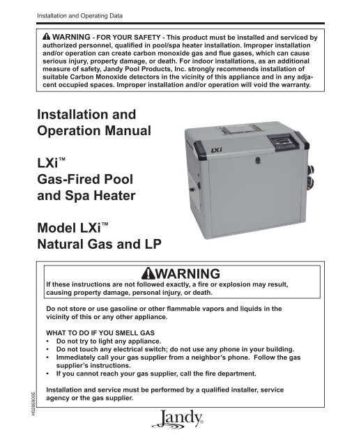
Jandy LXi : installation and operation manual - Piscines et Spas ...
Jandy LXi : installation and operation manual - Piscines et Spas ...
Jandy LXi : installation and operation manual - Piscines et Spas ...

You also want an ePaper? Increase the reach of your titles
YUMPU automatically turns print PDFs into web optimized ePapers that Google loves.
<strong>LXi</strong> Pool/Spa Heater Installation <strong>and</strong> Operation Manual Page 7Any changes to the heater, gas controls, gasorifices, wiring, draft diverter, or improper <strong>installation</strong>may void the warranty. If change is required to any ofthe above, consult the factory.1.5 Technical AssistanceConsult <strong>J<strong>and</strong>y</strong> Pool Products, Inc. or your local<strong>J<strong>and</strong>y</strong> distributor with any questions or problemsinvolving the specifications, <strong>installation</strong>, <strong>and</strong> <strong>operation</strong>of your <strong>J<strong>and</strong>y</strong> equipment. An experienced memberof the technical support staff is ready to assist you inassuring the proper performance <strong>and</strong> application of<strong>J<strong>and</strong>y</strong> products. For technical support, call the TechnicalService Department at 1.707.776-8200,extension 260.1.6 Materials Installer Must Provide1.6.1 Materials for All ApplicationsThe following items are needed <strong>and</strong> are to besupplied by the installer for all <strong>LXi</strong> heater<strong>installation</strong>s:1. The correct size gas pipe to supply gas from them<strong>et</strong>er to the heater. See Section 4.1.2. A <strong>manual</strong>ly operated gas valve to be installed inthe gas line outside of the heater jack<strong>et</strong>.3. A suitable gas union joint to connect the heater tothe gas line outside of the heater.4. Plumbing items needed to provide a sedimenttrap (drip leg) in the gas line b<strong>et</strong>ween the <strong>manual</strong>gas valve <strong>and</strong> the heater. See Section 4.1.5. A 120V AC or 240V AC power supply. A junctionbox is not needed at the heater; connectionsare made inside of the heater jack<strong>et</strong>.1.6.2 Materials for SpecialApplicationsIn addition to the items listed above, the followingitems are needed for special applications:1. A factory authorized vent collar <strong>and</strong> any ventpipe needed for indoor <strong>installation</strong>s in the USA<strong>and</strong> outdoor shelter <strong>installation</strong>s in Canada. (SeeSection 3.3.2). A vertical vent collar comes withthe unit. A side vent kit is available from your<strong>J<strong>and</strong>y</strong> distributor.2. Primer <strong>and</strong> cement suitable for cementing CPVCpipe to PVC pipe <strong>and</strong> an appropriate couplingfor connecting the factory supplied CPVC pipenipples to PVC pool plumbing.3. A noncombustible platform for <strong>installation</strong> oncombustible surfaces. (See Section 2.3.3.) Noncombustiblebases are available from your <strong>J<strong>and</strong>y</strong>distributor.1.7 Specifications1.7.1 General Specifications1. Installation Location:Certified for use:In the USA:Natural Gas:LP:In Canada:Natural Gas :LP:Indoor <strong>and</strong> OutdoorIndoor <strong>and</strong> OutdoorOutdoor <strong>and</strong> OutdoorShelterOutdoor <strong>and</strong> OutdoorShelter2. Minimum Clearance From CombustibleMaterial:See Table 2 in Section 2.3.2.3. *Gas Pipe/Heater Gas Valve Connection:Natural Gas:3/4" NPTLP:3/4" NPT*For diam<strong>et</strong>er of gas line from m<strong>et</strong>er to heater, see Table 5 inSection 4.1.4. Supply Gas Type:Certified for use with:Natural Gas <strong>and</strong> LP5. Inl<strong>et</strong> Gas Supply Pressure:Minimum MaximumNatural Gas: 5.0 "WC 10.5 "WCLP: 11.0 "WC 14.0 "WC6. Air Plenum Pressure: 1.5 "WC7. Burner Throat Pressure: 1.0 "WC8. Water Pipe/Heater Connection:*2" Unthreaded PVC or CPVC*Other size pipes may be used. See Section 5.5 for d<strong>et</strong>ails9. Water Flow Rate:Maximum:Minimum:10. Working Water Pressure:Maximum: 75 psi125 gpm (475 lpm)30 gpm (110 lpm)11. Exhaust Vent Connection Size:Model:250 6" Diam<strong>et</strong>er300 7" Diam<strong>et</strong>er400 8" Diam<strong>et</strong>er
Page 8<strong>LXi</strong> Pool/Spa Heater Installation <strong>and</strong> Operation Manual12. Electrical Supply:Either 120 Volts AC or 240 Volts AC.13. Modification of Heater for High Altitude:<strong>LXi</strong> heaters are normally shipped from the factoryin the low altitude (sea level) <strong>operation</strong>alconfiguration. Table 1 defines the altitude designationsas described by the St<strong>and</strong>ard for GasFired Pool Heaters, ANSI Z21.56 in the UnitedStates <strong>and</strong> Gas-Fired Appliances For Use AtHigh Altitudes, CAN1-2.17 in Canada. Whenan <strong>LXi</strong> heater is to be installed in a high altitudeapplication, the burner throat pressure will needto be adjusted to achieve 1.0"WC. See Section10.4.3 for instructions on how to do this.1.7.2 DimensionsSee Figure 1 for a diagram showing the heater'sexterior dimensions <strong>and</strong> dimensions to critical connectionson the heater.Table 1. Altitude Designations For The <strong>LXi</strong> HeaterALTITUDEDESIGNATIONNATURAL GASUNITEDSTATESCANADALOW ALTITUDE 0-4500 FT 0-4500 FT(0-1370 M)HIGH ALTITUDE 4501-10,000 FT NOTAPPLICABLELPLOW ALTITUDE 0-4500 FT 0-4500 FT(0-1370 M)HIGH ALTITUDE 4501-10,000 FT NOTAPPLICABLEA6.9”(17.5 cm)22.3”(56.6 cm)27.5”(69.9 cm)18.5”(47 cm)13.1”(33.3 cm)11.2”(28.4 cm)15.5”(39.4 cm)6.0”(15.2 cm)5.5”(14 cm)Figure 1. General ConfigurationHeater WidthModel Dim "A"Vent Diam<strong>et</strong>er Firing Ratein. cm in. cm BTU/HR kcal250 23.5 59.7 6 15.2 250,000 63300 26.5 67.3 7 17.8 300,000 75400 32.0 81.3 8 20.3 399,000 101
<strong>LXi</strong> Pool/Spa Heater Installation <strong>and</strong> Operation Manual Page 9Section 2. Installation Instructions2.1 IntroductionWARNINGImproper <strong>installation</strong> or maintenance can causenausea or asphyxiation from carbon monoxide infl ue gases which could result in severe injury, ordeath. For indoor <strong>installation</strong>s, as an additionalmeasure of saf<strong>et</strong>y, <strong>J<strong>and</strong>y</strong> Pool Products, Inc.strongly recommends <strong>installation</strong> of suitable CarbonMonoxide d<strong>et</strong>ectors in the vicinity of this appliance<strong>and</strong> in any adjacent occupied spaces.AVERTISSEMENTUne <strong>installation</strong> ou un entr<strong>et</strong>ien inadéquat peutcauser la nausée ou l’asphyxie en raison dumonoxyde de carbone présent dans les gaz decombustion <strong>et</strong> même entraîner des blessuresgraves ou la mort. Pour les <strong>installation</strong>s intérieures,comme mesure de sécurité additionnelle,<strong>J<strong>and</strong>y</strong> Pool Products, Inc. recomm<strong>and</strong>e fortementl’<strong>installation</strong> de détecteurs de monoxyde decarbone près de c<strong>et</strong> appareil ainsi que dans lesespaces adjacents occupés.Install the <strong>LXi</strong> heater <strong>and</strong> vent collar in accordancewith the procedures in this <strong>manual</strong>, local codes<strong>and</strong> ordinances, <strong>and</strong> in accordance with the latest editionof the appropriate national code. See Section 1.4,Codes <strong>and</strong> St<strong>and</strong>ards.All gas-fired products require correct <strong>installation</strong>to assure safe <strong>operation</strong>. The requirements for poolheaters include the following:1. Field assembly (if required)2. Appropriate site location (clearances) <strong>and</strong> flooring3. Sufficient combustion <strong>and</strong> ventilation air4. Properly sized gas m<strong>et</strong>er <strong>and</strong> piping5. Proper electrical wiring (if required)6. Adequate water flowThis <strong>manual</strong> provides the information needed tome<strong>et</strong> these requirements. Review all application <strong>and</strong><strong>installation</strong> procedures compl<strong>et</strong>ely before continuingthe <strong>installation</strong>.2.2 Field AssemblyThe <strong>LXi</strong> heater can be installed in a vari<strong>et</strong>y ofways, some of them requiring preparation or assemblyin the field. The heater is shipped from the factorywith an exhaust vent configured for an outdoor <strong>installation</strong>.The <strong>LXi</strong> heater is also design certified for “Indoor”<strong>installation</strong>s in the United States <strong>and</strong> “OutdoorShelter” <strong>installation</strong>s in Canada when equipped with avent collar <strong>and</strong> the appropriately sized exhaust vent.Check the rating plate on the heater or the PartsList (Section 11.2) in this <strong>manual</strong> for the correct <strong>J<strong>and</strong>y</strong>vent collar part number. For specific <strong>installation</strong> informationsee Section 2.3.5, Indoor <strong>and</strong> Outdoor ShelterInstallations.Water connections are provided on the right sideof the heater but can be changed to the left side byreversal of the heat exchanger. It is best to h<strong>and</strong>le thesepreparations before the heater is installed in its final location.See Section 5.4, Reversible Water Connections,in this <strong>manual</strong> for instructions.2.3 Location Requirements2.3.1 IntroductionCAUTIONWhen pool equipment is located below the pool surface,a leak from any component can cause largescale water loss or fl ooding. <strong>J<strong>and</strong>y</strong> Pool Products,Inc., cannot be responsible for such water loss orfl ooding or resulting damage.ATTENTIONLorsque l’équipement d’une piscine est situé sousla surface de l’eau, une fuite provenant de n’importequel élément peut causer une perte d’eau importanteou une inondation. <strong>J<strong>and</strong>y</strong> Pool Products, Inc. n’estpas responsable des pertes d’eau, des inondationsou des avaries causées par une <strong>installation</strong> ou unentr<strong>et</strong>ien inadéquat.The <strong>LXi</strong> heater may be installed indoors oroutdoors, as outlined in later sections. Location ofthe heater below or above the pool water level affects<strong>operation</strong> of its water pressure switch. See sections onwater piping <strong>and</strong> heater start-up for more informationabout this.Avoid placing the heater in locations where it cancause damage by water or condensate leakage. If thisis not possible, provide a suitable drain pan to catch<strong>and</strong> divert any leakage. The pan must not restrict theair flow around the heater.All criteria given in the following sections reflectminimum clearances as stated in the national st<strong>and</strong>ards.However, each <strong>installation</strong> must also be evaluated,taking into account the prevailing local conditionssuch as wind speed <strong>and</strong> direction, proximity <strong>and</strong> heightof walls that may block ventilation, <strong>and</strong> proximity topublic access areas.2.3.2 ClearancesThe heater must be placed to provide clearanceson all sides for maintenance <strong>and</strong> inspection. Theremust also be minimum distances maintained fromcombustible surfaces. See Table 2.At least 18" (457mm) access must be available infront of the heater for burner removal <strong>and</strong> access tothe igniter.If the heater is to be installed in a garage, or
Page 10<strong>LXi</strong> Pool/Spa Heater Installation <strong>and</strong> Operation ManualTable 2. Minimum Heater Clearances From Combustible SurfacesTable 2. Dégagements Minimaux à Assurer Entre les Parois deL'appareil <strong>et</strong> les Constructions CombustiblesSIDE OFHEATERINDOOR (OUTDOORSHELTER) INSTALLATIONOUTDOOR INSTALLTIONINCHES CENTIMETERS INCHES CENTIMETERSBLANK 4 10.2 4 10.2REAR 4 10.2 4 10.2PIPING 16 40.6 16 40.6TOP 36 99.0 OPEN UNROOFED AREAFRONT 18* 45.7* 18* 45.7*Note: Clearances listed in Table 2 aremanufacturer's tested values. These aregiven as minimum values. Where local<strong>and</strong> national codes apply, <strong>and</strong> valuesare different than those listed in Table2, use the greater value to ensure safe<strong>operation</strong>.* In Canada - 24 in (61cm)similar structure, all burners <strong>and</strong> burner ignition devicesmust have a minimum 18" (457mm) clearanceabove the floor.This heater must be installed at least 5 fe<strong>et</strong>(1.52m) from the inside wall of a pool unless theheater is separated from the pool by a solid fence, wallor other permanent solid barrier.Ce chauffe-piscine doit être installé au moins 5pieds (1.52m) de la paroi interne de la piscine à moinsd'être isolé de la piscine par une clôture, un mur ouautre barrière permanente.2.3.3 FlooringThe heater must be installed on a level surfaceof noncombustible construction or on fire-resistantslabs or arches. Noncombustible flooring is definedas flooring material <strong>and</strong> surface finish not capable ofbeing ignited <strong>and</strong> burning <strong>and</strong> with no combustiblematerials against the underside. Acceptable materialsare those consisting entirely of a combination of steel,iron, brick, tile, concr<strong>et</strong>e, slate, glass or plaster. Do notinstall the heater directly on a combustible wood orcarp<strong>et</strong> floor without placing a noncombustible platformb<strong>et</strong>ween the floor <strong>and</strong> the heater.The heater can be installed on a combustible floorif a noncombustible base assembly, available from<strong>J<strong>and</strong>y</strong>, is used. See the heater rating plate or the PartsList (Section 11) in this <strong>manual</strong> for the appropriatebase part number. Heaters must never be installeddirectly on carp<strong>et</strong>ing.As an alternative to the <strong>J<strong>and</strong>y</strong> noncombustiblebase plate, in the United States, the National Fuel GasCode (NFPA 54 / ANSI Z223.1), <strong>and</strong> in Canada, theNatural Gas <strong>and</strong> Propane Installation Code (CAN/CSA-B149.1), allow a heater to be placed on a combustiblesurface when there is a platform under theheater made of hollow masonry no less than 4 inches(102 millim<strong>et</strong>ers [mm]) thick, covered with she<strong>et</strong>m<strong>et</strong>al at least 24 gauge thick <strong>and</strong> extending beyond thefull width <strong>and</strong> depth of the heater by at least 6 inches(153 mm) in all directions. The masonry must be laidwith ends unsealed, <strong>and</strong> joints matched to provide freecirculation of air from side to side through theNotes:1. Blocks must provide a solid base <strong>and</strong> be braced so theycannot slip out of place.2. Air openings in blocks must be arranged to provide unrestrictedopening through entire width or length of base.3. She<strong>et</strong> m<strong>et</strong>al must be at least 24 ga. <strong>and</strong> extend 6" beyondthe heater jack<strong>et</strong> on all sides.Figure 2. Noncombustible Platformmasonry. (See Figure 2.) If the heater is installed in acarp<strong>et</strong>ed alcove, the entire floor of the alcove must becovered by a noncombustible panel.2.3.4 Outdoor InstallationThe <strong>LXi</strong> heater can be installed in the outdoorconfiguration as received from the factory.Locate the heater in an open, unroofed area. Donot install the heater under a deck. Do not locate theheater below or adjacent to any doors, glass openings,louvers, grills, <strong>et</strong>c., which connect in any way with aninhabited area of a building, even though the accessmight be through another structure (e.g., a garage orutility room). In the United States the vent systemshall terminate at least 4 ft (1.2 m) below, 4 ft (1.2 m)
<strong>LXi</strong> Pool/Spa Heater Installation <strong>and</strong> Operation Manual Page 11horizontally from, or 1 ft (300 mm) above any door,operable window, or gravity inl<strong>et</strong> into any building. InCanada, the heater must be installed so that the exhaustpoint of the heater is at least ten (10) fe<strong>et</strong> (3.0 m) fromany building opening. See Figure 3.WARNINGUnited StatesDo not install the heater with the top of the ventassembly within 4 fe<strong>et</strong> (1.22 m) horizontally, 4 fe<strong>et</strong>(1.22 m) below or less than 1 ft (300 mm) above ofany opening into a building.CanadaDo not install the heater with the top of the vent assemblywithin 10 fe<strong>et</strong> (3.05 m) of any opening into abuilding.AVERTISSEMENTLorsque vous installez l’appareil de chauffage, assurez-vousque l’ouverture d’aération se trouve à unminimum de 10 pieds (3.05 m) de toute ouvertured’un bâtiment.The top surface of the heater must be at least 3fe<strong>et</strong> above any forced air inl<strong>et</strong>, or intake ducts locatedwithin 10 fe<strong>et</strong> horizontally.If the heater is installed under an overhang, theremust be a minimum clearance of 5 fe<strong>et</strong> (1.5 m) abov<strong>et</strong>he top of the heater <strong>and</strong> the structure should not overhangthe heater more than 12 inches (0.30 m). The areaunder the overhang must be open on three sides. Thisprevents combustion gases from being diverted intoliving areas through doors, windows, or gravity inl<strong>et</strong>s.If the heater is installed close to a structure, protectit from rain water runoff with rain gutters on theroof or other measures. Do not locate the heater nearirrigation sprinkler systems that could spray water onit. Water from sprinklers may cause damage to controls<strong>and</strong> electronic components.Avoid locations where wind deflection off nearbystructures might cause downdraft conditions. Wheredowndraft conditions exist, locate the heater at least 3fe<strong>et</strong> (0.91 m) from vertical surfaces (e.g., nearby buildings<strong>and</strong> walls).In Florida, it is required that the heater be securelyfastened to the equipment pad. Use a size1/4" x 1-1/2" long stainless steel Tapcon ® type concr<strong>et</strong>escrews <strong>and</strong> washers at each of the four tabslocated at the base of the heater. Mounting the appliancein this manner me<strong>et</strong>s the applicable requirementsof the Florida Building Code.Tapcon ® is a registered trademark of Illinois Tool Works (ITW), Inc.Mounting screws are not provided with this heater.After placing the heater on the equipment pad, drilla hole in the concr<strong>et</strong>e at each of the four tabs on thefe<strong>et</strong> of the heater. (The correct size drill bit is usuallyprovided with the concr<strong>et</strong>e screws when purchased).Place a screw in each of the holes <strong>and</strong> fasten the heaterto the equipment pad. (See Figure 4). Do not overtorqu<strong>et</strong>he screws.Ne pas installer ce chauffe-piscine sous unesaillie mesurant moins de 3 pi de hauteur. La partiesous la saillie doit être ouverte sur 3 côtés.Figure 4. Anchor Heater To Equipment PadFigure 3. Outdoor Heater Installation2.3.5 Indoor <strong>and</strong> Outdoor ShelterInstallationsAn outdoor shelter (Canada only) is an unoccupiedenclosure which does not communicate directlywith occupied areas. All indoor <strong>installation</strong>s <strong>and</strong>outdoor shelter <strong>installation</strong>s require a factory approvedvent collar. The vent collar must be installed withoutmodification <strong>and</strong> in accordance with the instructionsprovided by the manufacturer. For sidewall venting, aside vent kit is available from your <strong>J<strong>and</strong>y</strong> distributor.
Page 12<strong>LXi</strong> Pool/Spa Heater Installation <strong>and</strong> Operation ManualUne remise extérieure (au Canada seulement)est un endroit inoccupé qui ne communiquepas directement avec les endroits occupés. Toutesles <strong>installation</strong>s intérieures <strong>et</strong> remises extérieuresexigent l’addition d’une cheminée approuvée par lemanufacturier. La cheminée doit être installée sansaucune modification <strong>et</strong> selon les exigences fourniespar le manufacturier.The applicable codes, st<strong>and</strong>ards <strong>and</strong> <strong>J<strong>and</strong>y</strong> PoolProducts, Inc., require that the heater be properlyvented as outlined in this <strong>manual</strong>. Proper ventilationof exhaust <strong>and</strong> combustion air are essential for the safe<strong>and</strong> efficient <strong>operation</strong> of the heater. See Section 3.2.3.5.1 Converting the Grill to a VentCollarIf the <strong>LXi</strong> heater is to be installed either indoorsor in an outdoor shelter, its exhaust discharge grillmust be removed. The <strong>LXi</strong> heater comes with thevertical vent collar factory installed. The optional sidevent plate, gask<strong>et</strong> <strong>and</strong> screws can be ordered as a partskit. (See the parts list in Section 11 of this <strong>manual</strong>).The conversion can be done quite simply as follows:1. Remove the vent exhaust grill by removing thefour screws which r<strong>et</strong>ain it. The grill <strong>and</strong> thescrews may be discarded. See Figure 5.2. Install the vent pipe on the indoor vent collar.The collar will accommodate vent piping of nominal6”, 7” or 8” diam<strong>et</strong>er (see Table 4), dependingupon the model of your heater. (See Figure6.) See vent <strong>installation</strong> section for importantinformation on selecting proper pipe size.Section 3. Venting3.1 Combustion Air SupplyThe heater location must provide sufficientair supply for proper combustion <strong>and</strong> ventilation ofthe surrounding area as outlined in the latest editionof ANSI st<strong>and</strong>ard Z223.1 (NFPA 54) or in Canada,CAN/CSA-B149.1, <strong>and</strong> any local codes that may beapplicable.In general, these requirements specify that theroom in which a heater is installed should be providedwith two permanent air supply openings; one within12 inches (305 mm) of the ceiling, the other within 12inches (305 mm) of the floor. All indoor <strong>installation</strong>smust have openings to outside air for combustion,ventilation, <strong>and</strong> dilution of flue gases from inside thebuilding. See Figure 7 <strong>and</strong> Table 3. <strong>J<strong>and</strong>y</strong> Pool Products,Inc., does not recommend indoor <strong>installation</strong>sthat do not provide combustion air from outside thebuilding.All outdoor shelter <strong>installation</strong>s (Canada only)must have uninterrupted openings to outside air forcombustion <strong>and</strong> ventilation. The <strong>installation</strong> must bein accordance with the latest edition of CAN/CSAB149.1. <strong>J<strong>and</strong>y</strong> Pool Products, Inc., does not recommendoutdoor shelter <strong>installation</strong>s that depend oninternal air for combustion. Combustion air should beducted to the heater from outside the structure.Outside Air Supply: When combustion air issupplied directly through an outside wall, each openingshould have a minimum free area of one squareinch per 4,000 BTU/h (1.2kW) input of the total inputrating of all appliances in the enclosed area. If air isprovided through horizontal ducts, each opening <strong>and</strong>duct must provide one square inch of flow area foreach 2000 BTU/h (0.6 kW). These requirements aresummarized in Table 3. Note that the areas specifiedare n<strong>et</strong> free areas <strong>and</strong> should be increased when theopenings are covered by screens, louvers, grills or otherprotective covers. See Figure 8 <strong>and</strong> Table 3 notes.NoteIn Canada, follow Canadian St<strong>and</strong>ard, CAN/CSA-B149.1 or local codes.Figure 5. Removal of Outdoor Exhaust GrillFigure 6. Vent Pipe InstallationOUTDOORVENT GRILLVERTICALVENTCOLLAR
<strong>LXi</strong> Pool/Spa Heater Installation <strong>and</strong> Operation Manual Page 13Notes:1. Use approvedroof jack.3)Figure 7. Indoor Installation Venting (USA), or Outdoor Shelter (Canada)Table 3. Air Openings to OutsideRequired N<strong>et</strong> Free Open Area*for Combustion Air OpeningsModelDirect from outside Duct from outsidein 2 (cm 2 ) in 2 (cm 2 )250 63 (406) 126 (813)300 75 (484) 150 (968)400 100 (645) 200 (1290)*Area indicated is for one of two openings; one at fl oor level <strong>and</strong>one at the ceiling, so the total n<strong>et</strong> free area would be double thefi gures indicated. For special conditions, refer to NFPA54 ANSIZ223.1. In Canada refer to the National St<strong>and</strong>ard CAN/CSA-B149.1 which differs from this table.Note: If using screens <strong>and</strong>/or m<strong>et</strong>al louvers, compensate by adding50% additional area to each opening. If using wood louvers each openingmust be at least four times the area indicated in the table above.Exhaust Fans or Vents: Any equipmentwhich exhausts air from the room where the heateris installed can depl<strong>et</strong>e the combustion air supply orreverse the natural draft action of the venting system.This could cause flue products to accumulate in theroom. Additional air must be supplied to compensatefor such exhaust.The information in Table 3 is not applicable in<strong>installation</strong>s where exhaust fans or blowers of any typeare used. Such <strong>installation</strong>s must be designed by qualifiedengineers.The heater must be compl<strong>et</strong>ely isolated <strong>and</strong>protected from any source of corrosive chemical fumessuch as those emitted by trichlor<strong>et</strong>hylene, perchloro<strong>et</strong>hylene,chlorine, <strong>et</strong>c.WARNINGDo not store any chemicals, cleaners, or other corrosivematerial near combustion air openings or inthe room. Avoid locating appliance vents in the vicinityof combustion air openings. Failure to preventcorrosive materials from mixing with combustion aircan result in reduced heater life <strong>and</strong> unsafe heater<strong>operation</strong>.AVERTISSEMENTNe pas entreposer ni utiliser d'essence ni d'autresvapeurs ou liquides infl ammables à proximité de c<strong>et</strong>appareil ou de tout autre appareil.3.2 Exhaust VentingWhen converted to indoor <strong>and</strong> outdoor shelterventing configuration, the <strong>LXi</strong> heater has a vent collarfitting for attachment to the venting. The diam<strong>et</strong>er ofthe vent collar <strong>and</strong>, thus, the minimum diam<strong>et</strong>er ofthe vent pipe to be used is d<strong>et</strong>ermined by the modelof heater installed <strong>and</strong> the type of venting. The onlycorrect procedure for vent pipe sizing is to do so inaccordance with Table 4 <strong>and</strong> the applicable <strong>installation</strong>code as stated in the following "Danger" warning.Note that with horizontal Category III type vent<strong>installation</strong>s, the venting may be smaller than the ventcollar for Category I vertical venting. See Table 4.
Page 14<strong>LXi</strong> Pool/Spa Heater Installation <strong>and</strong> Operation ManualHeaterSizeVent Collar SizeMinimum VerticalVent Pipe Diam<strong>et</strong>er(Refer to NFPA 54 orlocal codes)Table 4. Vent Pipe Sizing TableHorizontal Vent PipeDiam<strong>et</strong>erMaximum HorizontalVent LengthMaximum No.of ElbowsSidewall Vent Kit250 6 in 15 cm 6 in 15 cm 5 in 13 cm 25 ft 7.6 m 3 R0467301300 7 in 18 cm 7 in 18 cm 5 in 13 cm 25 ft 7.6 m 3 R0467301400 8 in 20 cm 8 in 20 cm 6 in 15 cm 25 ft 7.6 m 3 R0467302WARNINGVent pipe diam<strong>et</strong>er must be as required by the Nationalfuel Gas Code Z223.1 or the Canadian InstallationCodes for Gas Appliances CAN/CSA-B149.1.Undersized pipe can result in inadequate venting<strong>and</strong> oversize pipe can result in vent condensation.In either case the result can be release of combustionproducts to the indoors. This can cause seriousinjury or death by carbon monoxide poisoning orasphyxiation.AVERTISSEMENTLe diamètre des tuyaux de ventilation doit répondreaux exigences du National Fuel Gas Code Z223.1ou du code canadien des <strong>installation</strong>s des appareilsà gaz CAN/CSA B149.1. Des tuyaux trop p<strong>et</strong>itsrisquent d’entraîner une ventilation inadéquate <strong>et</strong>des tuyaux trop gros risquent de provoquer unecondensation dans les tuyaux. Dans un cas commedans l’autre, des produits de combustion risquentde s’échapper dans le bâtiment <strong>et</strong> causer des blessuresgraves ou l’asphyxie par le monoxyde decarbone.3.3 Vent Pipe Sizing <strong>and</strong> GeneralInstallationThe <strong>LXi</strong> may be installed with venting as a CategoryI or III Fan-Assisted appliance or outdoors withthe integral vent grill.3.3.1 Outdoor InstallationsFor outdoor <strong>installation</strong>s, exhaust venting considerationswill d<strong>et</strong>ermine the placement of the heater(See Section 2.3.4). If the heater cannot be placed soas to me<strong>et</strong> the requirements stated in Section 2.3.4,a vent collar may be added to the heater to move theexhaust vent opening to a position that complies withthe requirements. In all cases, vent collars must be ofthe same diam<strong>et</strong>er as the exhaust outl<strong>et</strong> of the heater.Approved vent collars may be obtained through your<strong>J<strong>and</strong>y</strong> distributor.3.3.2 Indoor <strong>and</strong> Outdoor ShelterInstallationsAll indoor <strong>installation</strong>s <strong>and</strong> outdoor shelter <strong>installation</strong>srequire a factory approved vent collar. Thevent collar must be installed without modification <strong>and</strong>the vertical vent collar comes factory installed.All vent <strong>installation</strong>s must be made in accordancewith all local, state or provincial codes <strong>and</strong>with:1. The National Fuel Gas Code, ANSI Z223.1(NFPA 54), latest edition; pay particular attentionto the chapter addressing “Venting ofEquipment.” Applicable provisions of additionalapplicable local building codes may also need tobe followed.2. In Canada, CAN/CSA B149.1.Avoid terminating heater vents near air conditioningor air supply fans. The fans can pick upexhaust flue products from the heater <strong>and</strong> r<strong>et</strong>urn theminside the building, creating a possible health hazard.Do not locate the vent terminal where flue productscould strike against building materials <strong>and</strong> causedegradation.Vent opening should be well away from treesor other obstructions that would prevent free air flowto <strong>and</strong> from vent terminal. Do not terminate the ventunder decks, stairways, or car ports.The <strong>LXi</strong> may be installed for use with st<strong>and</strong>ardvertical venting per tables provided in most localcodes for Category I Fan-Assisted appliances. If thelocal code does not include such tables, refer to theNational Fuel Gas Code NFPA 54 / ANSI Z223.1 orthe Canadian Natural Gas <strong>and</strong> Propane InstallationCode, CAN/CSA-B149.1. Note that the tables forfan-assisted appliances include both maximum <strong>and</strong>minimum vent loading figures. The primary purposeof the maximum ratings are to assure that the ventoperates with negative pressure throughout its length.The minimum ratings are to assure that vent gases donot cool too much <strong>and</strong> thereby assure that condensationdoes not occur.When the <strong>installation</strong> requires horizontal ventingin excess of what is allowed for Category I <strong>installation</strong>sor calls for horizontal discharge, the <strong>LXi</strong> may beinstalled with a Category III venting system. CategoryIII applications must be installed per this <strong>installation</strong><strong>manual</strong> <strong>and</strong> the vent manufacturer's <strong>installation</strong>instructions. The venting materials must comply withUL 1738 for Category III venting systems <strong>and</strong> be constructedof stainless steel. In Canada, the venting materialsmust be ULC S636 compliant. Vent piping mustbe adequately supported with no low spots or saggingthat will allow condensate to collect. The heater mustnot be used to support the vent pipe. Horizontal runs
<strong>LXi</strong> Pool/Spa Heater Installation <strong>and</strong> Operation Manual Page 15must be sloped upwards away from the heater to a ventterminal at a minimum of 1/4" per horizontal foot (2cm/m). The <strong>LXi</strong> is designed for Category III ventingwith a maximum of 25 ft (7.6 m) of vent pipe <strong>and</strong> upto 3 elbows. For each additional elbow, reduce themaximum vent pipe length by 10 ft (3 m). See Table 4for the minimum vent diam<strong>et</strong>er for the model size tobe installed.Side wall vents must be installed <strong>and</strong> located inaccordance with the National Fuel Gas Code NFPA54 / ANSI Z223.1 or the Canadian Natural Gas <strong>and</strong>Propane Installation Code CAN/CSA-B149.1. SeeFigure 8 Side Wall Vent Terminations.IMPORTANT NOTE In the Commonwealth ofMassachus<strong>et</strong>ts, additional requirements,covered in document CMR 248 5.00, whichsupersede some of the requirements ofANSI Z223.1 (NFPA 54) apply to Side WallHorizontally Vented appliances. If installingthis product using an approved side-wallhorizontal vent system in the Commonwealthof Massachus<strong>et</strong>ts, be sure to adhere to theseadditional requirements. These requirementsinclude verbiage that says that the propertyowner is to ensure that Carbon MonoxideD<strong>et</strong>ectors are installed in the vicinity ofthe appliance <strong>and</strong> also on all levels of thedwelling in which the appliance is installed.For further instructions, contact <strong>J<strong>and</strong>y</strong> PoolProducts Technical Service Department at(707) 776-8200 extension 260.NOTE For approved side wall vent kits <strong>and</strong> specifi c<strong>installation</strong> instructions, see Section 11,Replacement Parts.When venting multiple appliances through onecommon duct, each appliance must have its own venttemperature limit switch. All vent limit switches mustbe wired in series so as to prevent any appliance fromfiring in the event of a blocked vent. Refer to ANSIZ223.1 or, in Canada, to CAN/CSA B149.1 for moreinformation on multiple venting.3.3.3 Inspection <strong>and</strong> Replacement ofExisting Vent System with NewComponentsIf the <strong>LXi</strong> is being installed to replace an existingpool heater, it is recommended that a new appropriateventing system be installed with the new heater. However,if an existing venting system must be used, besure to carefully inspect the venting system to ensur<strong>et</strong>hat it is in good condition <strong>and</strong> continues to be appropriatefor the <strong>LXi</strong> heater. Replace any parts that arenot in good <strong>and</strong> serviceable condition with new partsbefore compl<strong>et</strong>ing the pool heater <strong>installation</strong>.Figure 8. Side Wall Vent Terminals
Page 16<strong>LXi</strong> Pool/Spa Heater Installation <strong>and</strong> Operation ManualSection 4. Gas Connections4.1 Gas Supply <strong>and</strong> PipingReview the following general instructions beforecontinuing the <strong>installation</strong>.WARNINGThe <strong>LXi</strong> pool <strong>and</strong> spa heaters are designed for usewith either natural gas or LP gas. Check the ratingplate on the inner panel to be sure that the heater isdesigned to use the type of gas being supplied. DONOT ATTEMPT TO CONVERT THIS HEATER FORUSE WITH ANY OTHER TYPE OF FUEL.AVERTISSEMENTLes appareils de chauffage à faibles émissions<strong>LXi</strong> pour piscines <strong>et</strong> cuves thermales sont conçuspour être utilisés avec du gaz naturel ou du gaz depétrole liquéfi é (GPL). Vérifi ez l’information inscritesur la plaque signalétique du panneau intérieur pourvous assurer que l’appareil est conçu pour le typede gaz fourni. NE PAS ESSAYER DE CONVERTIRCET APPAREIL À UN AUTRE TYPE DE GAZ.1. Gas piping <strong>installation</strong> must be in accordancewith the latest edition of ANSI Z223.1 <strong>and</strong> alllocal codes. In Canada, the <strong>installation</strong> must be inaccordance with CAN/CSA B149.1 <strong>and</strong> all localcodes that apply.2. Check the gas supply to be sure that it is the sameas the gas indicated on the heater's rating plate.<strong>LXi</strong> heaters, as shipped from the factory, are s<strong>et</strong>to operate within the low altitude range. Followthe instructions in Section 10.4.3 to adjust theheater for high altitude.CAUTIONPermanent damage to the gas valve will occur if thefollowing procedures are not followed.HeaterSizeTable 5. Supply Gas Pipe Size Requirements*0-50 fe<strong>et</strong>(0-15 m)Distance from Gas M<strong>et</strong>er50-100 fe<strong>et</strong>(15-30 m)100-200 fe<strong>et</strong>(30-60 m)in. mm in. mm in. mm250 1 25 1-1/4 32 1-1/4 32300 1-1/4 32 1-1/4 32 1-1/2 38400 1-1/4 32 1-1/2 38 1-1/2 38Notes:*1. These numbers are for natural gas (0.65 Sp. Gr.) <strong>and</strong>are based on 1/2 inch (3.45 kPa) water column pressuredrop. Check supply pressure with a manom<strong>et</strong>er, <strong>and</strong> localcode requirements for variations. For LP gas, reducepipe diam<strong>et</strong>er by one size, but maintain a minimum3/4" diam<strong>et</strong>er.2. Check supply pressure <strong>and</strong> local code requirements beforeproceeding with work.3. Pipe fi ttings must be considered when d<strong>et</strong>ermining gaspipe sizing.4. Install a sediment trap (drip leg) ahead of the gascontrols. See Figure 9. Fit the trap with a threadedcap which can be removed for cleaning.5. Install a <strong>manual</strong> gas shutoff valve for service<strong>and</strong> saf<strong>et</strong>y. Do not use a restrictive gas cock.DO NOT USE FLEXIBLE GAS PIPING, it willrestrict the gas flow to the heater.6. Disconnect the heater <strong>and</strong> its individual shutoffvalve from the gas supply system during pressur<strong>et</strong>esting of the system at pressures higher than 1/2pounds per square inch (psi) (3.45 kilopascals[kPa]). If the test pressure is equal to or less than1/2 psi (3.45 kPa), close the <strong>manual</strong> shutoff valveon the heater during the piping pressure test.APPROVEDATTENTIONVous endommagerez la soupape de gaz si vous nerespectez pas les procédures suivantes.3. Use the figures in Table 5 to size the gas inl<strong>et</strong>piping from the gas m<strong>et</strong>er to the heater. Check alllocal codes for compliance before installing theheater.Figure 9. Proper Design for a Sediment Trap/Drip Leg
<strong>LXi</strong> Pool/Spa Heater Installation <strong>and</strong> Operation Manual Page 177. If the gas supply pressure is less than required,check for undersized pipe b<strong>et</strong>ween the m<strong>et</strong>er <strong>and</strong>the heater, a restrictive fitting, or an undersizedgas m<strong>et</strong>er. Gas supply pressures to the heater arelisted in Table 6.Table 6. Gas Supply Pressure Requirements*Supply Pressure Minimum MaximumNatural Gas 5.0 inches W.C.(1.2 kPa)10.5 inches W.C.(2.6 kPa)LP GasManifold PressureNatural GasLP Gas11.0 inches W.C.(2.5 kPa)14.0 inches W.C.(3.5 kPa)Nominal2.5 inches W.C. (0.6 kPa)9.0 inches W.C. (2.2 kPa)NOTE The maximum inl<strong>et</strong> gas pressure must notexceed the specifi ed value. The minimum valuelisted is for the purpose of input adjustment. Referto Table 6.8. To connect the gas supply line to the heater’s gasvalve, make sure the steel elbow (supplied withthe manifold) is screwed into the inl<strong>et</strong> side of thegas valve. The heater is designed so that the gassupply line may enter through either side of theheater. Tighten the elbow until the desired orientationis achieved.CAUTIONDo not overtighten the elbow. Over tightening willcrack the gas valve. Do not use tefl on tape to wrapthe elbow threads.ATTENTIONNe serrez pas trop le coude. Vous risqueriez de fi s-surer la soupape de gaz. N’entourez pas le fi l<strong>et</strong>agedes coudes de ruban à joints.9. Before operating the heater, test the compl<strong>et</strong>e gassupply system <strong>and</strong> all connections for leaks usinga soap solution. Do not use an open flame.CAUTIONSome leak test solutions (including soap <strong>and</strong> water)may cause corrosion or stress cracking. Rinse thepiping with water after testing.ATTENTIONCertaines solutions d’essai d’étanchéité (y comprisl’eau <strong>et</strong> le savon) peuvent causer de la corrosionou de la fi ssuration. Rincez les tuyaux à l’eau aprèsl’essai d’étanchéité.4.2 Manifold PressureConfirm that gas supply pressure is correct. Ifthe gas supply pressure is less than required, checkfor undersized pipe b<strong>et</strong>ween the m<strong>et</strong>er <strong>and</strong> the heater,a restrictive fitting, or an undersized gas m<strong>et</strong>er. Gassupply pressures to the heater, when it is operating, arelisted in Table 6.CAUTIONManifold gas pressure for the <strong>LXi</strong> natural gas heatersshould be s<strong>et</strong> at 2.5" WC. Propane heatersshould be s<strong>et</strong> to 9" WC.ATTENTIONLa pression du collecteur de pression pour lessystèmes de chauffage au gaz naturel devrait êtrede 2.5'’ WC. Pour les sytèmes de chauffage au gazpropane devrait être de 9'’ WC.The manifold pressure may be checked by connectinga manom<strong>et</strong>er to the pressure port on the outl<strong>et</strong>side of the valve. The pressure will be zero when theheater is not running. When the heater is operating themanifold gas pressure should be 2.5" WC for naturalgas heaters <strong>and</strong> 9.0" WC for LP gas heaters.If the manifold pressure indicated above is notcorrect, check the gas train for possible problems.Check the m<strong>et</strong>er, gas line, gas fittings, <strong>and</strong> gas shut offfor under sizing. Check the gas valve inl<strong>et</strong> for excesspipe dope, if all is correct, then it may be necessary toadjust the gas valve regulator. To adjust the manifoldgas pressure, first remove the slotted cap next to theinl<strong>et</strong> pressure port on the inl<strong>et</strong> side of the gas valve.Under the slotted cap is a slotted plastic screw whichincreases the manifold pressure when turned clockwise<strong>and</strong> decreases the manifold pressure when turnedcounterclockwise. After measurements, <strong>and</strong> adjustmentsif necessary, have been made, make sure toreplace the 1/8" NPT gas valve plugs on the inl<strong>et</strong> <strong>and</strong>manifold pressure ports, <strong>and</strong> the cap on the manifoldpressure adjustment screw. It is extremely importantto replace these parts before leaving the <strong>installation</strong>.Failure to do so can result in damage to property or injuryor death. With the heater fi ring, the pressure mustbe within the range shown in Table 6. Also check thepressure with the heater off.4.3 Special Precautions for LP GasLP Gas is heavier than air <strong>and</strong> can therefore morereadily collect or “pool” in enclosed areas if provisionfor proper ventilation is not made. Installation of poolheaters in enclosed areas such as pits is not recommended.However, if such an <strong>installation</strong> is requiredbe sure to pay special attention to proper ventilationrequirements for LP gas. Locate heaters a safe distancefrom LP gas cylinders <strong>and</strong> filling equipment.Consult the National Fuel Gas Code (NFPA 54 / ANSIZ223.1, latest edition), the Natural Gas <strong>and</strong> PropaneInstallation Code in Canada (CAN/CSA B149.1, latestedition), <strong>and</strong> any other local codes <strong>and</strong> fire protectionauthorities about specific <strong>installation</strong> restrictions inyour area.
Page 18<strong>LXi</strong> Pool/Spa Heater Installation <strong>and</strong> Operation ManualSection 5. Water Connections5.1 Water PipingFigure 10 illustrates typical piping for poolequipment in pool/spa combination pools. With itselectronic control, the <strong>LXi</strong> heater is particularly suitedfor this type of pool <strong>installation</strong>.The heater must be protected from back-siphoningof water, which can result in dry starts. If there isany chance of back-siphoning, provide a check valveb<strong>et</strong>ween the pool <strong>and</strong> the filter pump inl<strong>et</strong>.Arrangement of pool system components otherthan as illustrated in these diagrams can affect the <strong>operation</strong>of the heater’s water pressure switch. Locationof the heater above or below the pool water surfacecan also affect <strong>operation</strong> of the switch. In general, thepressure switch can be adjusted to accommodate thiseffect if the heater water connections are no more thansix (6) fe<strong>et</strong> below the pool water surface <strong>and</strong> no mor<strong>et</strong>han 15 fe<strong>et</strong> above it. See instructions for pressureswitch adjustment (Section 7.7) for more informationabout this.Note that when pool equipment is located belowthe pool surface a leak can result in large scale waterloss or flooding. <strong>J<strong>and</strong>y</strong> Pool Products, Inc., cannot beresponsible for such water loss or flooding or the damagecaused by either occurrence.5.2 Check Valve InstallationInstall a check valve in the plumbing b<strong>et</strong>weenthe pool inl<strong>et</strong> <strong>and</strong> the heater if there is any chance ofback-siphoning.Do not install any valve in the piping b<strong>et</strong>ween theheater outl<strong>et</strong> <strong>and</strong> the pool, unless it is being used as adiverter valve. For special <strong>installation</strong>s, such as waterconnections below the water level of the pool, or forother questions contact the Technical Service departmentat 1.707.776.8200 ext. 260.5.3 Automatic Flow Control ValveThe inl<strong>et</strong>/outl<strong>et</strong> header of the <strong>LXi</strong> heater comesequipped with an automatic flow control valve. Theautomatic flow control valve maintains the properflow through the heater at rates up to approximately125 Gallons Per Minute (GPM) (475 liters per minute[LPM]). If the filter system flow rate is higher thanapproximately 125 GPM (475 LPM), install a <strong>manual</strong>bypass valve (see Figure 11), then perform a temperaturerise test (see Section 7.8) <strong>and</strong> adjust the flow usingthe bypass valve until the proper temperature rise isobtained.5.4 Reversible Water ConnectionsThe <strong>LXi</strong> heater is shipped with water connectionson the right side, but can be modified in the fieldto provide left-side water connections. This procedureinvolves removing the heat exchanger headers <strong>and</strong>reinstalling them on opposite ends of the tube assembly.Some of the heater wiring must be disconnected<strong>and</strong> re-routed, so this procedure must be done only bya trained service technician. Heat exchanger reversalsare generally done before the <strong>installation</strong> of power<strong>and</strong> water to the heater. If you need to reverse the heatexchanger on a previously installed heater be sure thatAQUAPUREFigure 10. Typical Piping Installation
<strong>LXi</strong> Pool/Spa Heater Installation <strong>and</strong> Operation Manual Page 19all electrical power, the gas supply <strong>and</strong> water supplyhave been turned off before starting the procedure.These instructions have been written to include thesteps needed when reversing the water connections onan existing <strong>installation</strong>. If you are reversing the headerson a new <strong>installation</strong>, some steps will be ignored.Water connection reversal is illustrated in Figures 11<strong>and</strong> 12. Proceed as follows:1. For an existing <strong>installation</strong>, drain the heater byremoving the two drain plugs on the inl<strong>et</strong>/outl<strong>et</strong>header <strong>and</strong> the drain plug on the r<strong>et</strong>urn header.2. Remove the heater front panel (door).3. Remove the I/O header side cover plates, top <strong>and</strong>bottom. See Figure 13.4. Remove the r<strong>et</strong>urn header side cover plate. SeeFigure 13.5. Disconnect the blue "HiLimit" two-pin connectorfrom the Power Interface board in the raceway.Clip any wire ties attached to the harness. Feedthe "HiLimit" two-pin connector <strong>and</strong> wiring backthrough the way it is routed to the header so thatthe harness hangs free from the header, outside ofthe cabin<strong>et</strong>.6. Disconnect the two "WATER TEMP" temperaturesensor leads from the Power Interface boardin the raceway. Clip any wire ties attached to theharness. Pull the wires out of the cabin<strong>et</strong> so thatthey hang free from the header, outside of thecabin<strong>et</strong>.7. Disconnect the yellow "Water Press" two-pinconnector from the Power Interface board inthe raceway. Clip any wire ties attached to theharness. Feed the "Water Press" two-pin connector<strong>and</strong> wiring back through the way it is routedto the water pressure switch so that the harnesshangs free from the water pressure switch, outsideof the cabin<strong>et</strong>.NOTE Be careful not to create any kinks in the waterpressure switch copper tubing when h<strong>and</strong>lingthe header.8. For an existing <strong>installation</strong>, remove the couplingnuts from the header <strong>and</strong> disconnect the watersupply from the heater.9. Remove the 10 bolts <strong>and</strong> washers from the inl<strong>et</strong>/outl<strong>et</strong> header <strong>and</strong> remove the header from th<strong>et</strong>ube assembly. Leave the spacer in place.10. Remove the 10 bolts <strong>and</strong> washers from the r<strong>et</strong>urnheader <strong>and</strong> remove the header from the tube assembly.Leave the spacer in place.11. For an existing <strong>installation</strong>, remove the tubegask<strong>et</strong>s <strong>and</strong> clean the header's mating surface ofany corrosion or debris. Replace the tube gask<strong>et</strong>swith new ones. Do not use any m<strong>et</strong>al tools on theFigure 11. Water Connections as ShippedSIDELEFTSIDESUPPORTTOPPANELREARPANELDOORSUPPORTGRILLREAR VENTCOVERSIDERIGHTSIDESUPPORTRETURNHEADER SIDECOVER PLATEBASEFRONTPANEL(DOOR)I/O HEADER SIDECOVER PLATESTOP AND BOTTOMFigure 12. Water Connections ReversedFigure 13. <strong>LXi</strong> Panel Identification
<strong>LXi</strong> Pool/Spa Heater Installation <strong>and</strong> Operation Manual Page 21WARNINGFollow all fi lter manufacturer'sinstructions. NEVER attempt toassemble, dis as sem ble or adjust thefi lter when there is pressurized air in thesystem. Starting the pump while thereis any pressurized air in the system cancause the fi lter lid to be blown off, whichcan cause death, serious personalinjury or property dam age.1. Turn off the electrical power to the heater. Turnoff the main gas supply to the heater at the m<strong>et</strong>eror the <strong>manual</strong> gas cock outside the heater.2 Be sure that the filter pump is OFF <strong>and</strong> that itwill remain off during the entire procedure.3. Open the relief valve on top of the filter <strong>and</strong>leave it open during the procedure.4. If the heater is below the surface level of the wa-HEAT RISEWARNINGTO BE ADJUSTED BYQUALIFIED SERVICEPERSONNEL ONLYDrainPlugsFigure 15. Header Drain Plug Locationter in the pool or spa, be sure to close all shut-offvalves b<strong>et</strong>ween the heater <strong>and</strong> the pool.5. Remove the drain plugs <strong>and</strong> drain the heater. SeeFigure 15.NOTE: Be sure to use 2" or 2½" schedule 40 PVCpipe.6. Clean the cut ends of the pipe <strong>and</strong> both ends ofthe sweep elbow(s) with an appropriate NSF ®approved All Purpose cleaner/primer. Glue thesweep elbow(s) onto the cut pipe ends using anappropriate All Purpose NSF ® approved adhesive/glue.See Figure 16.NOTE: <strong>J<strong>and</strong>y</strong> recommends Weld-On 724 PVC toCPVC Cement to glue Schedule 40 PVC.7. After the glue is cured, close the pressure reliefvalve on top of the filter, start the system <strong>and</strong>check for proper water flow.8. Replace the drain plugs.9. R<strong>et</strong>urn all valves to their operating positions.10. Restore power to the heater.11. Turn on the pump to check for water leaks.12. Restore the gas supply to the heater.To connect a section of 2" PVC or CPVC pip<strong>et</strong>o the heater, first slip a coupling nut onto the pipe.Then prepare the end of the pipe with the proper PVC/CPVC primer <strong>and</strong> glue. Follow the manufacturer’sinstructions provided with the primer <strong>and</strong> glue forSweep ElbowP/N SEAQL10017½”MinimumSweep ElbowP/N SEFL1002<strong>LXi</strong> HeaterCV FilterSHPPumpFigure 16. <strong>LXi</strong> Heater Sweep Elbow Installation
Page 22<strong>LXi</strong> Pool/Spa Heater Installation <strong>and</strong> Operation ManualPVC OR CPVC PIPEO-RINGSTART WITH A 1/4" BITTHEN OPEN HOLE WITHA 3/8" BIT THEN OPENHOLE WITH A 1/2" BITTEMPORARILYINSTALL BRASSADAPTER TOPROTECT PLASTICTHREADSCOUPLINGCOUPLINGNUTFigure 17. Piping to Heaterpreparation procedures <strong>and</strong> curing times. Apply theslip-fit side of the coupling to the end of the pipe. Allowthe glue to cure compl<strong>et</strong>ely. S<strong>et</strong> the o-ring into thegroove on the face of the coupling. Slide the couplingnut up to the coupling <strong>and</strong> tighten it to the threadedconnection on the header. See Figure 17.NSF ® is a registered trademark of NSF International.5.6 Pressure Relief ValveA pressure relief valve (PRV) is recommended inall <strong>installation</strong>s, <strong>and</strong> is m<strong>and</strong>atory in any <strong>installation</strong>in which the water flow can be shut off b<strong>et</strong>ween theheater outl<strong>et</strong> <strong>and</strong> the pool/spa.A pressure relief valve is not supplied with the<strong>LXi</strong> heater. However, it is recommended that a pressurerelief valve be installed <strong>and</strong> may even be requiredby local codes. Be sure to check any applicable<strong>installation</strong> codes in your area to d<strong>et</strong>ermine wh<strong>et</strong>hera pressure relief valve is required. See Section 11.2(Parts List) of this <strong>manual</strong> for the appropriate kit partnumber.The maximum working pressure of this heater is75 psi. Be sure to take into consideration the maximumallowable pressure of the other components in the systemwhen selecting a PRV. Any pressure relief valveinstalled must comply with provisions of the st<strong>and</strong>arddescribed in ANSI Z21.22 for the United Sates or CSA4.4 in Canada.Follow these steps to install a pressure relief valve.1. To protect the threads while drilling, screw thebrass adapter (included with the <strong>J<strong>and</strong>y</strong> PRV kit)into the blind threaded hole on the top of theinl<strong>et</strong>/outl<strong>et</strong> header.2. Using the countersink in the center of the blindhole as a guide, drill a ¼" hole through the plastic.See Figure 18.3. Open the hole by reaming it with a ⅜" drill bit.4. Open the hole again by reaming it with a ½" drillbit.Figure 18. Drill Hole for Pressure Relief ValvePRESSURE RELIEFVALVE HANDTIGHTEN ONLYRUBBER WASHERFigure 19. Pressure Relief Valve InstallationCAUTIONInitially drilling a ½" hole without reaming maycause the bit to "grab" on the plastic. This maycause personal injury or damage the plastic header.ATTENTIONSi vous commencez à percer le trou de ½" sansalésage préalable, la mèche risque de « mordre »dans le plastique. Vous risquez de vous blesser oud’endommager le tuyau collecteur de plastique.5. Remove the brass adapter <strong>and</strong> clean the cuttingsout of the hole.6. Install the rubber washer at the bottom of thehole. See Figure 19.7. Thread the adapter into the hole <strong>and</strong> tighten sothat it seals against the rubber washer.OUTOUTBRASS ADAPTER8. With a permanent marker, place a mark on the
<strong>LXi</strong> Pool/Spa Heater Installation <strong>and</strong> Operation Manual Page 23adapter so that the mark faces the same directionas the water connections on the header.9. Remove the adapter from the hole.10. Coat the threads of the pressure relief valve(PRV) with an appropriate m<strong>et</strong>al to m<strong>et</strong>al threadsealant.11. Install the adapter on the PRV <strong>and</strong> tighten usingtwo wrenches. Use the mark made earlier on theadapter to orient the PRV to the desired directionin relation to the water connections on the header.12. Wrap the threads of the adapter with a suitabl<strong>et</strong>eflon thread tape.13. Reinstall the adapter, with the PRV, into the plasticthreaded hole <strong>and</strong> tighten it until the mark onthe adapter is once again facing the same directionas the water connections on the header.CAUTIONDo not use any pipe compound or pipe dope onthe threads of the adapter or any part that comes incontact with the plastic headers. These compoundsmay damage the header over a period of time.ATTENTIONN’utilisez ni pâte à joint ni pâte lubrifi ante sur lefi l<strong>et</strong>age du raccord intermédiaire ou sur toute piècequi entre en contact avec le tuyau collecteur. Cesproduits risquent d’endommager le tuyau après uncertain temps.DO NOT TIGHTEN WITH A WRENCH.Overtightening may crack the header. Route thedischarge piping so that discharge from the pipe doesnot endanger anyone near the heater. Refer to yourlocal <strong>installation</strong> codes for more d<strong>et</strong>ailed information.The valve s<strong>et</strong>ting should be at or below the maximumworking pressure of any component in the filtersystem. The maximum working pressure of the <strong>LXi</strong>heater is 75 psig.5.7 Auxiliary Components,Chlorinators, Ozone Generators,<strong>and</strong> Sanitizing ChemicalsThe <strong>LXi</strong> heater is manufactured with materialsthat are not compatible with high concentrations ofozone, chlorine, bromine, or other sanitizing chemicals.Heater damage caused by excessive chemicalsor improper ozonization is not covered by the <strong>J<strong>and</strong>y</strong>Pool Products, Inc., warranty. Be sure to adhere to thefollowing:• When ozone is injected upstream of the heater,install an offgas mixing chamber, or an ozonebypass system b<strong>et</strong>ween the heater <strong>and</strong> the ozoneinjector to prevent ozone <strong>and</strong> air from enteringthe heater.• When chemical feeders are used, plumb thefeeder downstream of the heater <strong>and</strong> install anin-line check valve b<strong>et</strong>ween the heater <strong>and</strong> thefeeder (a minimum of 18" is required b<strong>et</strong>weenthe heater <strong>and</strong> the check valve).• Wire any electrical chemical feeder so that itcannot operate unless the filter pump is running.If the feeder has an independent clock control,synchronize it with the filter clock.• Never deposit chemicals directly in the poolskimmer.Section 6. ElectricalWARNINGELECTRICAL SHOCK HAZARD. This heater containswiring that carries high voltage. Contact withthese wires may result in severe injury or death.AVERTISSEMENTPOSSIBILITÉ DE CHOCS ÉLECTRIQUES. Cesystème de chauffage contient du fi lage de hautvoltage. Un contact avec ces fi ls peut résulter endes blessures sérieuses ou la mort.CAUTIONLabel all wires prior to disconnection when servicingcontrols. Wiring errors can cause improper <strong>and</strong>dangerous <strong>operation</strong>.Verify proper <strong>operation</strong> after servicing.ATTENTIONAu moment de l'entr<strong>et</strong>ien des comm<strong>and</strong>es,étiqu<strong>et</strong>ez tous les fi ls avant de les débrancher. Deserreurs de câblage peuvent entraîner un fonctionnementinadéquat <strong>et</strong> dangereux.6.1 General InformationWiring connections must be made exactly asshown in the wiring diagram found on the inside of theheater door. See Figure 20. The heater must include adefinite means of grounding. There is a bonding lug onthe right side of the heater, where a bond wire must beattached.6.2 Main PowerElectrical wiring must be in accordance with thelatest edition of the National Electric Code (NEC),ANSI/National Fire Protection Association (NFPA) 70,unless local code requirements indicate otherwise.The heater comes factory-wired intended foruse with 240 Volt, 60 Hz AC field electrical supply.To use 120 Volt, 60 Hz AC requires changing theposition of the voltage selector board on the powerdistribution board. This must be done by a certifiedelectrician only, as with all wiring. Be sure that thepower source to the heater is turned off or disconnectedbefore servicing.
Page 24<strong>LXi</strong> Pool/Spa Heater Installation <strong>and</strong> Operation ManualTRANSFORMERFUSEWRBKAlternate 120V Wiring*BL24 VACY120 VACHEATERPOWERSUPPLYNEUTRALHOTRBKGVoltage Selector Card Must Be Rotated.240 VACHEATERPOWERSUPPLYRBKGRBLWBKBKBKACN1F1L2L1ACH1F2WBKBLWBKBLROBLOWERMOTORWWATERTEMPSENSOROPTTEMPSENSORBKBKBRYWATERTEMPCOIL/AIRTEMPGASVALVEUNIVERSALCONTROLLERPOWER INTERFACEJVARETURNJVAINTAKEFAN/LOUVERPUMPCOMP/IGN24VACBK/YOY/BKRYUSERINTERFACE1HIPRESS/HILIMITLOPRESS/FUSELINKWATERPRESSREVVALVEREMOTESPA POOL COMBK O BL RBK BKBL O GY VUNIVERSALCONTROLLERUSER INTERFACEPOWERINTERFACEBK O BL R130FLIMITSWITCHBK150FLIMITSWITCHFUSIBLELINKWATERPRESSSWITCHNOTES: IF ANY OF THE ORIGINAL WIRE AS SUPPLIED WITH THEHEATER MUST BE REPLACED, APPLIANCE WIRING MATERIAL RATEDFOR 105°C MUST BE USED. WHERE MARKED THUS - - - - - - - - ,APPLIANCE WIRING MATERIAL RATED FOR 200°C MUST BE USED. - - - - - -* See Section 6.2. for Compl<strong>et</strong>e D<strong>et</strong>ails.BL BK RF1 F2 24 FV+ FV-VACIGNITION CONTROLIGN120 L1 L2 IGNFS PSW W VAL GNDGY BK W BK O Y/BK BR YOBR YGAS VALVEGYHOT SURFACEIGNITERWY/BKC NONCAIR FLOWSWITCHBKFLAME SENSETO COMBUSTIONAIR LOUVER STARTER(IF USED)TO PUMP STARTERCONTACTS (IF USED)Factory Wired 24VFactory Wired 120V/240VBK - BLACKBK/Y - BLACK WITH YELLOW TRACEBL - BLUEBR - BROWNG - GREENGY - GRAYO - ORANGER - REDV - VIOLETW - WHITEY - YELLOWY/BK - YELLOW WITH BLACK TRACEH0287800HFigure 20. <strong>LXi</strong> Connections/Schematic Wiring Diagram
<strong>LXi</strong> Pool/Spa Heater Installation <strong>and</strong> Operation Manual Page 25NOTE If the heater is converted to accept 120V, the“Hot” wire of the 120V power supply has tobe connected to the black wire (ACH1) on thepower distribution board <strong>and</strong> the “Neutral” wireof the 120V power supply has to be connectedto red wire (ACN1) of the power distributionboard.To wire the <strong>LXi</strong> heater to a 120V or 240V /60Hertz (Hz) electrical source:1. Remove the door of the heater.2. Connect the wires from the power source to theleads on the right side of the heater in the spacebehind the raceway. See Figure 21.NOTE No external junction box is required.6.2.1 Converting the Heater for a120V Power SourceTo convert the <strong>LXi</strong> heater to 120 Volt, 60 Hz ACrequires reversal of the voltage selector board on thepower distribution board. The following procedureshould be performed before the heater is connected toa power source:1. Identify the power distribution board on theheater. It is located to the right of the ignitioncontrol on the raceway. See Figure 22.2. Cut the plastic wire tie that is holding the voltageselector board in place <strong>and</strong> discard the wir<strong>et</strong>ie. Unplug the voltage selector board from thereceptacle. See Figure 23.3. Rotate the voltage selector board 180° <strong>and</strong>reinsert it into the receptacle so that the hole inthe board is not visible. Be sure that the board issecurely seated in the receptacle.NOTE The voltage selector board is keyed so that itwill fi t in only one direction for either selectedvoltage (either side of the board).6.3 BondingCAUTIONTo prevent premature failure of the appliance resultingfrom stray voltages <strong>and</strong> voltage differentials, theheater must be bonded to other equipment which ispart of the pool plumbing system with a solid copperwire not smaller in diam<strong>et</strong>er than 8 AWG (6 AWG inCanada).ATTENTIONPour éviter le bris prématuré de l'appareil dû àdes tensions vagabondes <strong>et</strong> à des différencesde tension, le chauffe-piscine doit être scellé àl'équipement faisant partie de la plomberie de lapiscine à l'aide d'un fi l de cuivre massif dont le diamètren'est pas inférieur à un calibre 8 (un calibre6 dans Canada).WIRES ASSHIPPEDCONNECTWIRES INSIDEHEATERFigure 21. Field Wiring ConnectionsIGNITIONCONTROLFigure 22. Location Of Power Distribution BoardCONDUITELBOWPOWERDISTRIBUTIONBOARDPOWERDISTRIBUTIONBOARDWIRE TIEVOLTAGESELECTORBOARDFigure 23. Power Distribution Board With VoltageSelector Board Installed for 240 VAC
Page 26<strong>LXi</strong> Pool/Spa Heater Installation <strong>and</strong> Operation Manual<strong>J<strong>and</strong>y</strong> Pool Products, Inc., requires that the appliancebe connected to a “bonding loop” that includes allelectrical equipment in the system <strong>and</strong> on the equipmentpad. Bonding lugs must be connected with asolid copper wire not smaller than 8 AWG (6 AWG inCanada). Failure to do so will void the <strong>J<strong>and</strong>y</strong> warranty.Additionally, in the United States the NationalElectrical Code (NEC) <strong>and</strong> in Canada the CanadianElectrical Code (CEC), require that all m<strong>et</strong>alliccomponents of a pool structure, including reinforcingsteel, m<strong>et</strong>al fittings <strong>and</strong> above ground components bebonded tog<strong>et</strong>her (forming an “equipotential bondinggrid”) with a solid copper conductor not smaller thanan 8 AWG (6 AWG in Canada).The NEC <strong>and</strong> CEC also require that the equipment<strong>and</strong>/or appliances associated with the pool watercirculating system, including, but not limited to, pumpmotors <strong>and</strong> heaters, be bonded tog<strong>et</strong>her as part of theequipotential bonding grid. <strong>J<strong>and</strong>y</strong> provides a speciallabeled bonding lug on the right side of the heater toaccommodate this requirement.6.4 Optional Pump Connection(Maintain Temp Feature)This optional feature allows the heater to turnon the pool pump, bypassing the time clock s<strong>et</strong>ting,to maintain the desired temperature. In order for theMAINTAIN TEMP feature to be functional, a relaymust be installed <strong>and</strong> a dedicated line from the poolpump time clock to the Maintain Temp (Pump) Relayis needed. See Figure 24. The relay <strong>and</strong> pertinentinstructions can be obtained by ordering <strong>J<strong>and</strong>y</strong> partnumber R0467200.6.5 Optional Remote ControlsWARNINGRISK OF ELECTRIC SHOCK WHICH CAN RE-SULT IN SERIOUS INJURY OR DEATH. Beforeattempting <strong>installation</strong> or service, ensure that allpower to the device is disconnected/turned off at thecircuit breaker.AVERTISSEMENTRISQUE DE CHOC ÉLECTRIQUE POUVANTCAUSER DES BLESSURES GRAVES OU LAMORT. Avant de tenter l’<strong>installation</strong> ou d’utiliser leservice, assurez-vous que l’alimentation allant versle dispositif soit débranchée/éteinte au niveau dudisjoncteur du circuit. Branchez seulement à uncircuit protégé par un disjoncteur de mise à la terre.Electrical wiring must be in accordance with thelatest edition of the National Electric Code (NEC),ANSI/National Fire Protection Association (NFPA) 70,unless local code requirements indicate otherwise.INTERMATIC MODEL T104 MECHANICAL TIMER(NOT PROVIDED WITH HEATER)4EQUIPMENTGROUNDCLOCKMOTOR123L2L1240 VAC PUMPFIELD INSTALLED COMPONENTSOPTIONAL HEATER COMPONENTSNOTE:MAINTAIN TEMP (PUMP) RELAY(SEE HEATER WIRING DIAGRAM)INTERMATIC MODEL T104 (NOT PROVIDED WITH HEATER) WIRE CONNECTIONS SHOWN AS AN EXAMPLE,OTHER MODELS MAY HAVE DIFFERENT CONNECTIONS. CONSULT TIMER MANUFACTURER FOR PROPER CONNECTIONS.Figure 24. Example of Maintain Temp Wiring to the Time Clock
<strong>LXi</strong> Pool/Spa Heater Installation <strong>and</strong> Operation Manual Page 276.5.1 Connection to a RemotePool-Off-Spa Selector (3-WireConnection)6.5.1.1 Install the Remote Pool-Off-SpaSelector1. Turn off the power to both the pool/spa controlsystem <strong>and</strong> the heater unit.2. Remove the front panel door from the front of theheater to access the raceway.3. Run the wires from the pool/spa control systemthrough the opening, located on the lower right orleft h<strong>and</strong> side of the heater.4. Connect the wiring from the pool/spa control systemto the heater remote control terminal.See Figure 25.Figure 25. Remote Pool-Off-Spa Connection (3-WireConnection)5. Restore power to the heater <strong>and</strong> the pool/spacontrol system.6.5.1.2 Configure the Control Panel1. Make sure the control is in the OFF mode.2. To enter the Service S<strong>et</strong>up mode, press <strong>and</strong> holdthe MENU, POOL, <strong>and</strong> SPA buttons for5 seconds.NOTE The display will revert back to OFF after oneminute since the last key press.3. Press the Up or Down button to display RE-MOTE. Press the MENU button.The SELECTREMOTE OFF (default remote) appears. Us<strong>et</strong>he Up or Down button to scroll through theRemote options. When you reach HI-LO-COM,press the MENU button to select the remote.Press POOL or SPA to exit Service S<strong>et</strong>up mode.6.5.2 Connection to an AquaLink ®RS Control System or RemoteTSTAT (2-Wire Connection)An interrupt (on/off) type remote can be connectedas a Remote TSTAT, as described in this section.This type of remote control will turn the heater on oroff, but will not perform any other function.This type of connection may be used to connecta <strong>J<strong>and</strong>y</strong> AquaLink ® RS Control System using any revisionlevel programmed control chip. The control willautomatically turn the heater on <strong>and</strong> off <strong>and</strong> will displaythe pool water temperature, but all other functionality<strong>and</strong> display information will be inactive. Whenusing this type of connection, remember to s<strong>et</strong> the <strong>LXi</strong>heater's control to “SPA” <strong>and</strong> s<strong>et</strong> the thermostat controlto maximum.Consult with the <strong>J<strong>and</strong>y</strong> Service Department,1.707.776.8200, extension 260, for questions aboutinstalling non-<strong>J<strong>and</strong>y</strong> remote controls.6.5.2.1 Install the Remote TSTAT1. Turn off the power to both the pool/spa controlsystem <strong>and</strong> the heater unit.2. Remove the front panel door from the front of theheater to access the raceway.3. Run the wires from the pool/spa control systemthrough the opening, located on the lower right orleft h<strong>and</strong> side of the heater.4. Connect the wiring from the pool/spa controlsystem to the heater remote control terminal. SeeFigure 26.Figure 26. AquaLink RS ® or Remote TSTAT Connection(2-Wire Connection)5. Restore power to the heater <strong>and</strong> the pool/spacontrol system.
Page 28<strong>LXi</strong> Pool/Spa Heater Installation <strong>and</strong> Operation ManualNOTE If you install a time clock to control the fi lterpump <strong>operation</strong>, it is recommended thatthe time clock have its own low voltage(Fireman’s) switch to turn off the heater befor<strong>et</strong>urning off the pump. The switch should shutoff the heater about 15 minutes before thefi lter pump shuts off. This will allow for a moreeffi cient <strong>operation</strong> by removing any residualheat contained in the heat exchanger back tothe pool.CAUTIONTo avoid damage to the heater, do not connect thepower supply of the heater to the output sideof the clock if your time clock simply interruptsthe high voltage power supply or has a high voltageoutput. Doing so will prevent the blower frompurging the residual heat from the heater when theheater turns off. The blower must be allowed to runfor 45 seconds after the heater shuts off.6.5.2.2 Configure the Control Panel1. Make sure the control is in the OFF mode.2. To enter the Service S<strong>et</strong>up mode, press <strong>and</strong> holdthe MENU, POOL, <strong>and</strong> SPA buttons for 5seconds.NOTE The display will revert back to OFF after oneminute since the last key press.3. Press the Up or Down button to display RE-MOTE. The SELECT REMOTE OFF (defaultremote) appears. Use the Up or Down button toscroll through the Remote options. When youreach REMOTE TSTAT, press the MENU buttonto select the remote. Press POOL or SPA toexit the Service S<strong>et</strong>up mode.4. Press SPA. Adjust the s<strong>et</strong>point to the maximums<strong>et</strong>ting of 104 °F.6.5.2.3 Remote OperationThe <strong>LXi</strong> pool/spa heater controls can be wiredfor remote <strong>operation</strong>. All <strong>J<strong>and</strong>y</strong> AquaLink ® RS ControlSystems will permit the heater to be operated byremote control.If you are s<strong>et</strong>ting up a new pool or spa system,call your local <strong>J<strong>and</strong>y</strong> distributor or the <strong>J<strong>and</strong>y</strong> CustomerService Department, 1.707.776.8200, extension 245,for information on the correct RS Control System tome<strong>et</strong> your needs.To provide “smart” communication b<strong>et</strong>ween the<strong>LXi</strong> <strong>and</strong> an AquaLink ® RS PCB Board through a redfour-pin RS485 connector, your PCB firmware mustbe Rev N or higher, as shown in Figure 28. To d<strong>et</strong>ermin<strong>et</strong>he REV of the PCB firmware in your systerm,refer to Table 7 <strong>and</strong> Figures 27 <strong>and</strong> 28.Connection toController:RS485ConnectorsIf your PCB firmware is REV MMM or lower, asshown in Figure 27, connect the heater to the controlas indicated in Section 6.5.2.If your PCB firmware is REV N or higher, asshown in Figure 28, continue to follow the proceduresin this section.Table 7. PCB Boards with Firmware REV MMM & REV NComponents REV MMM REV NRS485ConnectorsJVA Sock<strong>et</strong>s24 VACRelay Sock<strong>et</strong>s24 VDCS1S2Spa SideSwitchOne s<strong>et</strong> of 4 Two s<strong>et</strong>s of 4Located on top ofboard10 total sock<strong>et</strong>s. 8located on bottom,2 on top of boardConnection toController:RS485 ConnectorsFilter PumpAux 14 3 2 1 4 3 2 1RESETAUTOSERVICETIME OUTFILTER PUMPAux 2Aux 3Aux 4AUX 1Relay Sock<strong>et</strong>s24 VDCSensors <strong>and</strong>Heater4 3 2 1 6 5 4 3 2 1 10 9 8 7 6 5 4 3 2 1Filter PumpAux 1RESETAUTOSERVICETIME OUTAux 2Relay Sock<strong>et</strong>s24 VDCFILTER PUMPAUX 1Aux 3AUX 2Figure 27. PCB Board with Firmware REV MMM or LowerSpaSideSwitch6 5 4 3 2 1 10 9 8 7 6 5 4 3 2 1AUX 2Aux 5Aux 6Aux 7AUX 3AUX 3AUX 4AUX 4RS6 & RS8 ONLYAux 4AUX 5RS6 & RS8 ONLYAUX 5Aux 5AUX 6Located on bottomof boardSensors<strong>and</strong>Heater11 total sock<strong>et</strong>s.All located onbottom of board.RS8 ONLYAUX 7JVA Sock<strong>et</strong>s24 VACJVA Sock<strong>et</strong>s24 VACIntakeR<strong>et</strong>urnCleanerSolarAUX 6RS8 ONLYAUX 7Aux 6Relay Sock<strong>et</strong>s24 VDCHEATERHEATERAux 7SOLARSOLARPOOL MODESPA MODESPA DRAINSPA FILLIntakeR<strong>et</strong>urnCleanerSolarSolar PumpElect. Htr.SpareRelay Sock<strong>et</strong>s24 VDCSolar PumpElect HtrPOOL MODESPA MODESPA DRAINSPA FILLRelay Sock<strong>et</strong>s24 VDCFigure 28. PCB Board with Firmware REV N or Higher
4 3 2 1 4 3 2 1 6 5 4 3 2 1 10 9 8 7 6 5 4 3 2 1To ControllerTo Remote To Sensors, <strong>et</strong>c.(red terminal bar) (brown terminal bar) (green terminal bar)RESETAUTOSERVICETIME OUTAUX 1AUX 2AUX 3AUX 4RS6 & RS8 ONLYAUX 5AUX 6RS8 ONLYAUX 7HEATERSOLARPOOL MODESPA MODESPA DRAINSPA FILL<strong>LXi</strong> Pool/Spa Heater Installation <strong>and</strong> Operation Manual Page 29Indoor ControllerFILTER PUMPPowerCenterBezelPower CenterRS ControlSystem4 3 2 1GR Y BK R22 Gauge4 ConductorWire<strong>LXi</strong> ControlFigure 29. Wiring an <strong>LXi</strong> to a <strong>J<strong>and</strong>y</strong> RS RemoteDo not connect more than two wires to any of th<strong>et</strong>erminals in the RS Control System when connectingperipheral devices. If connecting the <strong>LXi</strong> heater to theRS Control System creates this situation, then a MultiplexingPCB kit must be used. Call your distributor or<strong>J<strong>and</strong>y</strong> Pool Products, Inc., to order the kit.To connect the <strong>LXi</strong> to your RS control system,refer to Figure 29 <strong>and</strong> follow the steps listed below.1. Turn off the power to both the heater <strong>and</strong> the RScontrol.2 Open the RS Power Center enclosure <strong>and</strong> remov<strong>et</strong>he front dead panel.NOTE Only an RS System with fi rmware revision "N",or higher, will support the <strong>LXi</strong> heater interface.Refer to Table 7 <strong>and</strong> Figures 27 <strong>and</strong> 28 tod<strong>et</strong>ermine the REV of your system's fi rmware.If it is "N" or higher, continue with theseprocedures. If it is MMM or lower, follow theprocedures in Section 6.5.2.3. Use 22 gauge 4-conductor wire (<strong>J<strong>and</strong>y</strong>part # 4278) to run b<strong>et</strong>ween the heater <strong>and</strong> theRS control, <strong>and</strong> match the wire color order.4. The wires coming from the <strong>LXi</strong> heater can be“doubled up” on the red terminal bar with thefour wires coming from the indoor controller.
Page 30<strong>LXi</strong> Pool/Spa Heater Installation <strong>and</strong> Operation ManualNOTE If you need to install more than two wires ineach terminal, order a <strong>J<strong>and</strong>y</strong> Multiplex PCBKit, which includes the Multiplex Board (<strong>J<strong>and</strong>y</strong>part # 6584). Never put more than two wiresinto each of the pins of the terminal bar.5. Check all wiring, then apply power to both theheater <strong>and</strong> the RS control system. Operation canbe verified in either Service or Auto mode. Seeyour RS Control System <strong>manual</strong> for instructionsabout <strong>operation</strong>.When the <strong>LXi</strong> heater is first powered on <strong>and</strong>there is an RS control connected to the heater, thedisplay on the heater control will show "JANDY RE-MOTE ONLINE PUSH MENU TO DISABLE".When the <strong>LXi</strong> heater is online with the RScontrol, all functionality of the control on the heater isdisabled. The heater functions can be controlled onlyat the RS unit.To temporarily use the heater controls, pressthe MENU button. The message "JANDY REMOTEONLINE PUSH MENU TO DISABLE" will disappearfrom the heater display. All functionality has now beenr<strong>et</strong>urned to the control on the heater. In this mode theRS unit is no longer controlling the heater.To r<strong>et</strong>urn the functionality to the RS unit, cycle(turn off <strong>and</strong> then turn on) the power to the heater, orpress the MENU button for 5 seconds to enter the UserS<strong>et</strong>up Mode <strong>and</strong> then enable the <strong>J<strong>and</strong>y</strong> Remote.6.5.3 Connection to a Secondary UseInterfaceThe <strong>LXi</strong> pool/spa heater can also be controlledremotely by installing a second wall mountable UserInterface. Please order <strong>J<strong>and</strong>y</strong> part number R0467500.This kit contains the second User Interface, wallmounting backplate, <strong>and</strong> necessary hardware.Section 7. Operating Instructions7.1 Normal OperationThe <strong>LXi</strong> heater is capable of automatic <strong>operation</strong>based on a call for heat at pres<strong>et</strong> temperatures <strong>and</strong>an operator selection b<strong>et</strong>ween pool or spa s<strong>et</strong>tings.Additionally, the heater may be controlled by a remoteunit to anticipate bather load, changes in temperatures<strong>et</strong>tings, or a vari<strong>et</strong>y of other dem<strong>and</strong>s that might beencountered. The heater has an internal saf<strong>et</strong>y systemwhich allows <strong>operation</strong> in a vari<strong>et</strong>y of conditions <strong>and</strong>prevents <strong>operation</strong> when certain adverse conditions areencountered. The heater is capable of diagnosing problemswithin the saf<strong>et</strong>y controls scheme, enabling fasterservice <strong>and</strong> less down time in the event of a failure.When the heater is powered, water is flowingthrough the heater, <strong>and</strong> the temperature of the waterentering the heater is below the temperature controls<strong>et</strong>ting, an operating cycle is initiated by the automaticcontrol. The combustion blower is started. If theblower pressure switch senses adequate airflow, the ignitionsequence starts. First, a fifteen second pre-purg<strong>et</strong>akes place. Next, the igniter is energized. After 40seconds of igniter heat-up time the gas valve is opened(approximately one minute after the call for heat). Ifflame is sensed at the burner within seven seconds,<strong>operation</strong> continues. Operation will continue until th<strong>et</strong>emperature of the water entering the heater reachesthe temperature control s<strong>et</strong>ting.If ignition is unsuccessful, or if the flame failsduring normal <strong>operation</strong>, the ignition control shuts offthe gas valve. It imposes a post purge, initiates additionalignition cycles, <strong>and</strong> shuts down the system ifignition is not achieved in three cycles. After one hour,the system will restart <strong>and</strong> try again.To res<strong>et</strong> the <strong>LXi</strong> heater to provide three (3) additionalattempts without waiting an hour, turn off thecontrol <strong>and</strong> then put it back in either the Pool or Spamode.7.2 Start-UpWARNINGFor your saf<strong>et</strong>y, when starting the heater, keep yourhead <strong>and</strong> face well away from the burner area toprevent any risk of personal injury.AVERTISSEMENTPour votre sécurité personnelle lorsque vous m<strong>et</strong>tezl’appareil en marche, tenez votre tête <strong>et</strong> votre visageloin du brûleur pour éviter tout risque de blessure.
<strong>LXi</strong> Pool/Spa Heater Installation <strong>and</strong> Operation Manual Page 31WARNINGVent pipes <strong>and</strong> heater tops g<strong>et</strong> hot! These surfacescan cause serious burns. Do not touch these surfaceswhile the heater is in <strong>operation</strong>.AVERTISSEMENTLes tuyaux d’aération <strong>et</strong> le dessus de l’appareildeviennent chauds! Ils peuvent causer de gravesbrûlures. Ne touchez pas à ces surfaces lorsquel’appareil est en marche.CAUTIONDo not use this heater if any part has been underwater. Immediately call a qualifi ed service technicianto inspect the heater <strong>and</strong> replace any part ofthe control system <strong>and</strong> any gas control which hasbeen under water.ATTENTIONN'utilisez pas c<strong>et</strong> appareil s'il a été plongé dansl'eau, même partiellement. Faites inspecterl'appareil par un technicien qualifi é <strong>et</strong> remplaceztoute partie du système de contrôle <strong>et</strong> toute comm<strong>and</strong>equi ont été plongés dans l'eau.CAUTIONShould overheating occur or the gas supply fail toshut off, turn off the <strong>manual</strong> gas control valve to theheater.ATTENTIONEn cas de surchauffe ou si l'alimentation en gaz nes'arrête pas, fermez manuellement le robin<strong>et</strong> d'arrêtde l'admission de gaz.CAUTIONDo not attempt repairs on the gas controls or appliance.Tampering is dangerous <strong>and</strong> voids all warranties.ATTENTIONNe tentez pas d’effectuer des réparations au systèmede régulation du débit du gaz ou à l’appareil.Toute modifi cation non autorisée est dangereuse <strong>et</strong>entraîne l’annulation de toutes les garanties.CAUTIONKeep all objects off the top of the heater. Blockingair fl ow could damage the heater <strong>and</strong> might void thewarranty.ATTENTIONNe posez aucun obj<strong>et</strong> sur le dessus de l’appareil.Il pourrait empêcher la circulation de l’air, ce quirisquerait d’endommager l’appareil <strong>et</strong> d’annuler lagarantie.Be sure that there is water in the pool <strong>and</strong> that thesurface level is above the skimmer or other inl<strong>et</strong> of thepool's filter system.Confirm that pool water is flowing normallythrough the pool system <strong>and</strong> equipment. With any newpool or spa <strong>installation</strong>, operate the filter pump withthe heater off long enough to compl<strong>et</strong>ely clean the water.This will remove any <strong>installation</strong> residue from thewater. Clean the filter at the end of this <strong>operation</strong> beforestarting the heater. Start the heater in accordancewith the Operating Instructions section of this <strong>manual</strong>,with particular attention to the lighting <strong>and</strong> shutdowninstructions <strong>and</strong> temperature control <strong>operation</strong>.The heater may not start on the first try. Air inthe gas line or other start-up situations may cause itto cycle. It will lock out if ignition is not achieved inthree (3) attempts. (See Section 9.2, Service Codes.)To res<strong>et</strong> the <strong>LXi</strong> heater to provide three (3) additionalattempts, turn off the control <strong>and</strong> then put it back ineither the Pool or Spa mode.When the heater starts, immediately feel theoutl<strong>et</strong> header of the heater to confirm that there is adequatewater flow. The header should not be hot. Normally,water temperature will rise only a few degreesas it passes through the heater, <strong>and</strong> a “hot” header orpipe indicates low water flow.WARNINGWhen the heater is fi red for the fi rst time, the combustionchamber refractory binder material is drivenout by the heat of the fl ame. White smoke <strong>and</strong>/orsharp odors may be emitted from the vent duringthis period. Do not inhale combustion product fumesat any time, <strong>and</strong> especially when these fumes arebeing emitted. This “burn-in” period will last only afew minutes.AVERTISSEMENTLorsque l’appareil est mis en marche pour lapremière fois, le matériau liant réfractaire de lachambre de combustion est expulsé par la chaleurde la fl amme. De la fumée blanche <strong>et</strong> de fortesodeurs peuvent se dégager du tuyau d’aération àce moment-là. N’inhalez les fumées de combustionà aucun moment, surtout au moment où elles sontémises. C<strong>et</strong>te période de combustion ne durera quequelques minutes.When raising the temperature of a cold pool,program the time clock to turn the pump off 23 hoursafter the start time. For example, if the start time is2:00 PM, then s<strong>et</strong> the stop time at 1:00 PM.. This l<strong>et</strong>sthe filter system <strong>and</strong> heater operate continuously untilthe water reaches the temperature s<strong>et</strong>ting on the temperaturecontrol. When that happens, the heater willautomatically shut off, but the filter pump will keeprunning.7.3 Operating the ControllerYour new <strong>LXi</strong> Pool Heater is controlled by an ad-
Page 32<strong>LXi</strong> Pool/Spa Heater Installation <strong>and</strong> Operation Manualvanced microprocessor based controller that providesa sophisticated y<strong>et</strong> simple interface to operate yourheater for maximum efficiency <strong>and</strong> enjoyment of yourpool. To locate the control buttons, see Figure 28.7.3.1 Off ModeWhen the control panel is turned off, the screendisplays GAS HEATER IS OFF PRESS POOL ORSPA.7.3.2 Pool Mode - (Normal Heat)To enable the pool mode, press POOL. The associatedleft green LED indicator will light <strong>and</strong> the unitwill display SET:XXX°.NOTE XXX represents the current temperatures<strong>et</strong>ting on the control. The default s<strong>et</strong>ting forpool temperature is 80°F (26°C).You can change the temperature s<strong>et</strong> point bypressing the Up or Down button. Repeatedly pressthe Up or Down button until you reach the desiredtemperature s<strong>et</strong> point. After 5 seconds of inactivity, thenew s<strong>et</strong> point is stored in memory.When the water temperature falls to 1˚ belowthe temperature s<strong>et</strong>ting, the control will start the heater<strong>and</strong> the associated right LED will light RED.7.3.3 Pool Mode - (Optional MaintainHeat)If connected, the Maintain Heat mode allowsthe heater to monitor the temperature of the water 24hours a day by turning the pool pump on <strong>and</strong> samplingthe water temperature. When the water temperaturedrops below the programmed temperature s<strong>et</strong> point,the control will start the heater.POOLGAS HEATER IS OFFPRESS POOL OR SPAMENUSPATo operate in pool mode with the Maintain Heatfeature, press POOL, then press MENU, press theDown button until MAINTAIN POOL HEAT is displayed,press the MENU button.The associated left green LED indicator will light<strong>and</strong> the unit will display SET:XXX°. Change the temperatures<strong>et</strong> point by pressing the Up or Down buttonuntil the desired s<strong>et</strong> point is displayed. After 5 secondsof inactivity, the new s<strong>et</strong> point is stored in memory.7.3.4 Spa Mode - (Normal Heat)To enable the spa mode, press SPA. The associatedleft green LED indicator will light <strong>and</strong> the unitwill display SET:XXX°.NOTE XXX represents the current temperatures<strong>et</strong>ting on the control. The default s<strong>et</strong>ting forspa temperature is 102°F (38°C).You can change the temperature s<strong>et</strong> point bypressing the Up or Down button. Repeatedly pressthe Up or Down button until you reach the desiredtemperature s<strong>et</strong> point. After 5 seconds of inactivity,the new s<strong>et</strong> point is stored in memory. When the watertemperature falls to 1˚ below the temperature s<strong>et</strong>ting,the control will start the heater <strong>and</strong> the associated rightLED will light RED.7.3.5 Spa Mode - (Optional MaintainHeat)If connected, the Maintain Heat mode allowsthe heater to monitor the temperature of the water 24hours a day.When the water temperature drops below theprogrammed temperature s<strong>et</strong> point, the control willstart the heater.To operate in spa mode with the Maintain Heatfeature, press SPA, then press MENU, press the Downbutton until MAINTAIN SPA HEAT is displayed, pressthe MENU button. The associated left green LED indicatorwill light <strong>and</strong> the unit will display SET:XXX°.Change the temperature s<strong>et</strong> point by pressing the Upor Down button until the desired s<strong>et</strong> point is displayed.After 5 seconds of inactivity, the new s<strong>et</strong> point isstored in memory.7.4 User S<strong>et</strong>up OptionsThe User S<strong>et</strong>up options allow the user to selectspecific Languages, Temperature Scale, Spa Timer,<strong>and</strong> Display Light options.7.4.1 Language S<strong>et</strong>up1. Make sure the control is in the OFF mode.Figure 28. Main Control Panel2. To enter the User S<strong>et</strong>up mode, press <strong>and</strong> hold theMENU button for 5 seconds.
<strong>LXi</strong> Pool/Spa Heater Installation <strong>and</strong> Operation Manual Page 33NOTE The display will revert back to OFF after oneminute since the last key press.3. To select a language, use the Up or Down buttonto display SELECT USER SETUP LAN-GUAGE. Press the MENU button. The SELECTLANGUAGE ENGLISH (default language)appears, use the Up or Down button to scrollthrough the language options. When you reachthe desired language, press the MENU button toselect the language. Press POOL or SPA to exitthe User S<strong>et</strong>up mode.7.4.2 Temperature Scale S<strong>et</strong>up1. Make sure the control is in the OFF mode.2. To enter the User S<strong>et</strong>up mode, press <strong>and</strong> hold theMENU button for 5 seconds.3. To select temperature scale, use the Up or Downbutton to scroll through to display SELECTUSER SETUP TEMPERATURE SCALE. Pressthe MENU button. The SELECT TEMP SCALE°F: (default temperature scale) appears, use theUp or Down button to scroll to display SELECTTEMP SCALE °C:. When you reach the desiredtemp scale, press the MENU button to select.Press POOL or SPA to exit the User S<strong>et</strong>up mode.7.4.3 Spa Timer S<strong>et</strong>up1. Make sure the control is in the OFF mode.2. To enter the User S<strong>et</strong>up mode, press <strong>and</strong> hold theMENU button for 5 seconds.3. To select spa timer, use the Up or Down buttonto scroll through to display SELECT USERSETUP SPA TIMER. Press the MENU button.The SELECT SPA TIMER CONTINUOUS: (defaultspa timer s<strong>et</strong>ting) is displayed. To turn thespa on or off indefinitely, press the MENU buttonto select.4. To select the length of time for the spa to run, us<strong>et</strong>he Up or Down button to scroll to display SE-LECT SPA TIMER TIME SELECTION. Pressthe MENU button to select. The display SELECTSPA TIME 01:00 HRS: (default time s<strong>et</strong>ting) isdisplayed. Use the Up or Down button to selectthe length of time for the spa to run (b<strong>et</strong>ween00:15 to 23:00 hours in increments of 00:15 minutes).Press the MENU button to select how longthe spa will run. Press POOL or SPA to exit theUser S<strong>et</strong>up mode.7.4.4 Display Light S<strong>et</strong>up1. Make sure the control is in the OFF mode.2. To enter the User S<strong>et</strong>up mode, press <strong>and</strong> hold theMENU button for 5 seconds.3. To select display light s<strong>et</strong>up, use the Up or Downbutton to scroll through to display SELECTUSER SETUP DISPLAY LIGHT. Press theMENU button. The SELECT DISPLAY LIGHT 2MIN TIMEOUT: (default display light s<strong>et</strong>ting) isdisplayed. This option allows the display light toturn off after 2 minutes. Press the MENU buttonto select. Use the Up or Down button to scrollto display SELECT DISPLAY LIGHT LIGHTOFF:, this option allows the display light to turnoff, press the MENU button to select. Use the Upor Down button to scroll to display SELECTDISPLAY LIGHT LIGHT ON:, this option allowsthe display light to turn on, press the MENUbutton to select. Press POOL or SPA to exit theUser S<strong>et</strong>up mode.7.5 S<strong>et</strong> Point LockoutMake sure the control is in the ON mode (POOLor SPA), press <strong>and</strong> hold the Up <strong>and</strong> Down buttons for5 seconds. The s<strong>et</strong> point will be locked <strong>and</strong> the controlwill operate in the mode it was in when the S<strong>et</strong> PointLockout occurred. If an attempt to change the s<strong>et</strong> pointis made while the control is in S<strong>et</strong> Point Lockout,the control will display SET POINT LOCKED. Tounlock the S<strong>et</strong> Point Lockout, press <strong>and</strong> hold the Up<strong>and</strong> Down buttons for 5 seconds. The unit will displaySET POINT UNLOCKED.7.6 Lighting <strong>and</strong> Shutdown ProceduresWARNINGDo not attempt to light the heater with the door off.Doing so may cause severe bodily injury.AVERTISSEMENTNe tentez pas d’allumer l’appareil sans que la portesoit en place. Vous pourriez être victime de blessurescorporelles graves.Before starting your heater, be sure that all ofthe functions <strong>and</strong> limits of the <strong>LXi</strong> controller has beens<strong>et</strong> according to the previous sections of this <strong>manual</strong>.Once the control is s<strong>et</strong> to your preferences, follow theinstructions outlined below. Read <strong>and</strong> follow all saf<strong>et</strong>yinstructions first. A more d<strong>et</strong>ailed s<strong>et</strong> of lighting <strong>and</strong>shutdown instructions are listed on the label located onthe inside of the heater door <strong>and</strong> in Figure 29.
Page 34<strong>LXi</strong> Pool/Spa Heater Installation <strong>and</strong> Operation ManualFOR YOUR SAFETY READBEFORE OPERATINGWARNING: If you do not follow these instructions exactly, afire or explosion may result, causing property damage, personalinjury or loss of life.A. This appliance does not have a pilot light. It is equipped with an ignition devicewhich automatically lights the heater. Do NOT try to light the burners by h<strong>and</strong>.B. BEFORE OPERATING, smell all around the appliance area for gas. Be sure tosmell next to the floor because some gas is heavier than air <strong>and</strong> will s<strong>et</strong>tle on thefloor.WHAT TO DO IF YOU SMELL GAS• Do not try to light any appliance• Do not touch any electric switch; do not use any phone in your building.• Immediately call your gas supplier from a neighbor's phone. Follow the gassupplier's instructions.• If you cannot reach your gas supplier, call the fire department.C. Use only your h<strong>and</strong> to push in or turn the gas control knob. Never us<strong>et</strong>ools. If the knob will not push in or turn by h<strong>and</strong>, don't try to repair it, calla qualified service technician. Force or attempted repair may result in a fireor explosion.D. Do not use this appliance if any part has been under water. Immediately calla qualified service technician to inspect the appliance <strong>and</strong> to replace anypart of the control system <strong>and</strong> any gas control which has been under water.OPERATING INSTRUCTIONS1. STOP! Read the saf<strong>et</strong>y information above on this label.2.* S<strong>et</strong> the thermostat for POOL <strong>and</strong> SPA to 70°F(21°C), or the lowest possibles<strong>et</strong>ting <strong>and</strong> switch the controller mode to OFF.3. Turn off all electric power to the appliance.4. This appliance is equipped with an ignition device which automatically lights theheater. Do not try to light the burners by h<strong>and</strong>.5. Remove the heater door.6. Turn gas control knob clockwise to OFF.7. Wait five (5) minutes to clear out any gas. Then smell for gas, including near thefloor. If you smell gas, STOP! Follow "B" in the saf<strong>et</strong>y information above on thislabel. If you don't smell gas, go to next step.8. Turn gas control knob counterclockwise to ON.9. Replace control access panel10. Turn on all electric power to appliance.11.* S<strong>et</strong> thermostat to desired s<strong>et</strong>tings for "Pool <strong>and</strong> Spa" <strong>and</strong> switch the controllermode from OFF to either POOL or SPA.12. If the appliance will not operate, check that the filter pump is on, the filter isclean <strong>and</strong> water is flowing to the pool. Otherwise, follow the instructions "ToTurn Off Gas To Appliance" <strong>and</strong> call your service technician or gas supplier.PRÉCAUTIONS À LIREAVANT D’UTILISERAVERTISSEMENT:Si vous ne suivez pas ces instructionsà la l<strong>et</strong>tre, il y a risque d’incendie ou d’explosion, pouvant entraînerdes dégâts matériels <strong>et</strong> des blessures graves voire mortelles.A. C<strong>et</strong> appareil ne possède pas de veilleuse. Il est équipé d’un dispositif quiallume automatiquement le chauffe-eau. Ne PAS essayer d’allumer lesbrûleurs à la main.B. AVANT DE METTRE EN MARCHE, humer pour s’assurer de l’absence de gazautour de l’appareil. Sentir à proximité du sol car certains gaz sont pluslourds que l’air <strong>et</strong> ne s’élèvent pas.MARCHE À SUIVRE EN CAS D’ODEUR DE GAZ• Ne pas tenter d’allumer aucun appareil.• Ne toucher à aucun interrupteur ; ne pas utiliser le téléphone dans le bâtiment.• Appeler immédiatement la compagnie de gaz en utilisant le téléphone d’unvoisin. Suivre les instructions données par celle-ci.• Si l’on n’arrive pas à joindre la compagnie de gaz, appeler les pompiers.C. Enfoncer <strong>et</strong> tourner le bouton de comm<strong>and</strong>e du gaz à la main uniquement.Ne pas utiliser d’outil. Si le bouton résiste, ne pas essayer de le réparer ;appeler un réparateur qualifié. Une réparation forcée ou mal faite peut causerun incendie ou une explosion.D. Ne pas utiliser c<strong>et</strong> appareil si une de ses pièces a été sous l’eau. Appelerimmédiatement un réparateur qualifié pour inspecter l’appareil <strong>et</strong> remplacertoute partie du circuit de comm<strong>and</strong>e <strong>et</strong> toute comm<strong>and</strong>e de gaz qui auraitsubi des dégâts d’eau.MODE D’EMPLOI1. ARRÊT! Lire les informations de sécurité fournies ci-dessus.2.* Régler le thermostat pour PISCINE <strong>et</strong> SPA à 70°F (21°C), ou le plus basarrangement, <strong>et</strong> commutez le contrôleur à ARRÊT.3. Couper toute arrivée de courant de l’appareil.4. C<strong>et</strong> appareil est équipé d’un dispositif qui allume automatiquement lechauffe-eau. Ne pas essayer d’allumer les brûleurs à la main.5. R<strong>et</strong>irer la porte du chauffe-eau.6. Tourner le bouton de comm<strong>and</strong>e du gaz dans le sens horaire jusqu’àARRÊT.7. Attendre cinq (5) minutes que le gaz se soit dissipé. Puis humer pours’assurer de l’absence de gaz, en particulier au niveau du sol. Si cela sentle gaz, ARRÊTER tout de suite ! Suivre les précautions de la partie “B”ci-dessus. S’il n’y a pas d’odeur de gaz, passer à l’étape suivante.8. Tourner le bouton de comm<strong>and</strong>e du gaz dans le sensanti-horaire jusqu’à ON.9. Rem<strong>et</strong>tre le panneau d’accès aux comm<strong>and</strong>es.10. Rem<strong>et</strong>tre l’appareil électrique sous tension.11.* Régler le thermostat aux règlages désirés pour PISCINE <strong>et</strong> SPA <strong>et</strong>commutez le contrôleur de ARRÊT, à soit PISCINE ou SPA.12. Si l’appareil électrique ne fonctionne pas, s’assurer que la pompe à filtre estallumée, que le filtre est propre <strong>et</strong> que la piscine est alimentée en eau. Sinon,suivre les instructions de “Coupure de l’arrivée de gaz de l’appareil” <strong>et</strong>appeler le réparateur ou la compagnie de gaz.TO TURN OFF GAS TO APPLIANCE1.* S<strong>et</strong> the thermostat for POOL <strong>and</strong> SPA to 70°F(21°C) or the lowest possibles<strong>et</strong>ting <strong>and</strong> switch the controller mode to OFF.2. Turn off all electric power to the appliance if service is to be performed.3. Turn gas control knob clockwise to OFF.4. Replace control access panel.*See <strong>manual</strong> for d<strong>et</strong>ails of <strong>operation</strong> of thermostat control.H0208200FCOUPURE DE L’ARRIVÉE DE GAZ DEL’APPAREIL1.* Régler le thermostat pour PISCINE <strong>et</strong> SPA à 70°F (21°C), ou le plus basarrangement, <strong>et</strong> commutez le contrôleur à ARRÊT.2. Couper toute arrivée de courant de l’appareil s’il doit subir une réparation.3. Tourner le bouton de comm<strong>and</strong>e du gaz dans le sens horaire jusqu’à OFF.4. Rem<strong>et</strong>tre le panneau d’accès aux comm<strong>and</strong>es.*Voir le manuel pour les détails concernant l'opération du contrôle de thermostat.Figure 29. Lighting <strong>and</strong> Shutdown Instructions
<strong>LXi</strong> Pool/Spa Heater Installation <strong>and</strong> Operation Manual Page 353. Turn off all electrical power to the heater at thejunction box.4. Open the heater door <strong>and</strong> turn the gas valve knobclockwise to off.5. Shut off the external gas supply valve to theheater.7.7 Adjusting the Water PressureSwitchFigure 30. Gas Valve7.6.1 Lighting the HeaterLighting instructions are as follows:1. Turn off all electrical power to the heater at themain junction box.2. Remove the heater door <strong>and</strong> turn the heater gasvalve to OFF.3. Wait 5 minutes before trying to start the heater.4. Turn the gas valve control knob counterclockwis<strong>et</strong>o ON. See Figure 30.5. Replace the heater door.6. Turn on electrical power to the heater.7. Turn on the filter pump.8. S<strong>et</strong> the heater control to the "SPA" mode. If th<strong>et</strong>emperature of the water exceeds the thermostats<strong>et</strong>ting it is necessary to increase the thermostats<strong>et</strong>ting to exceed the water temperature. Adjustthe thermostat s<strong>et</strong>ting (desired temperature) to begreater than the water temperature. The igniterlights the burner when the thermostat calls forheat.9. S<strong>et</strong> the time clock, if one is installed.7.6.2 ShutdownCompl<strong>et</strong>e shutdown instructions are as follows:1. S<strong>et</strong> both temperature controls to their lowest s<strong>et</strong>ting.2. Turn off the control. Make sure the display showsthat the heater is off.CAUTIONThe water pressure switch should be adjusted toturn the heater off when the pump is off. S<strong>et</strong>ting theswitch to close at too low of a fl ow can damage theappliance. Adjust the switch to turn the heater off,not on.ATTENTIONLe manocontact de pression d’eau doit être régléde façon à ce que l’appareil cesse de fonctionnersi la pompe s’arrête. Si le manocontact est réglépour se fermer lorsque le débit d’eau est trop faible,l’appareil risque de s’endommager. Réglez le manocontactpour qu’il arrête l’appareil, <strong>et</strong> non pour qu’ille m<strong>et</strong>te en marche.The pressure switch is pres<strong>et</strong> at the factory foractivation at 2 psi (14 kPa). Do not adjust the pressureswitch if the heater is installed more than 15 fe<strong>et</strong> (4.57m) below the pool surface. Consult your local <strong>J<strong>and</strong>y</strong>representative for recommendations.On some <strong>installation</strong>s, the piping from the heaterto the pool is very short. The back pressure could b<strong>et</strong>oo low to trigger the pressure switch. If this happens,it may be necessary to install a directional fitting orelbows where the r<strong>et</strong>urn line enters the pool. This willincrease back pressure enough for the heater to operateproperly.Figure 31. Adjustment of Pressure Switch
Page 36<strong>LXi</strong> Pool/Spa Heater Installation <strong>and</strong> Operation ManualMake sure the pool filter is clean before makingany pressure switch adjustment. A dirty filter willrestrict the water flow <strong>and</strong> the pressure switch cannot beadjusted properly.To adjust the pressure switch, refer to Figure 31<strong>and</strong> proceed as follows:BYPASSADJUSTMENTSCREW1. S<strong>et</strong> the heater control to the "OFF" mode.2. Remove the side panel above the front header toaccess the water pressure switch.3. Start the filter pump <strong>and</strong> confirm by means of avoltm<strong>et</strong>er that the pressure switch closes (if theswitch fails to close, replace it with a switch thathas a lower minimum s<strong>et</strong>ting).4. S<strong>et</strong> the heater control to either POOL or SPA.Heater should start.5. Pry out the top cap on the pressure switch.6. Use a 7/32" Allen wrench to turn the adjustmentscrew very slowly clockwise until the heater goesoff.7. Slowly turn the pressure switch adjustment screwcounterclockwise one-quarter turn. The heatershould come back on.8. Check the adjustment by turning the filter pumpOFF. The heater fan will continue to run but theburners should shut off immediately. If they donot, restart the filter pump <strong>and</strong> repeatSteps 6 <strong>and</strong> 7. Check the adjustment again.9. R<strong>et</strong>urn the pool temperature control to the desiredtemperature.It may be necessary to repeat these steps to g<strong>et</strong> aproper s<strong>et</strong>ting. The switch must be s<strong>et</strong> so that the heaterwill not fire unless the pump is running. If a propers<strong>et</strong>ting cannot be reached, contact the factory servicedepartment.7.8 Temperature RiseThe <strong>LXi</strong> pool <strong>and</strong> spa heaters have an internal bypasswhich accommodates a wide range of water flow.The bypass is easily adjustable to change the temperaturerise for optimum performance <strong>and</strong> length of heaterlife. The bypass assures constant heat exchanger floweven though flow through the filter system will varydepending on how dirty the filter is.For most <strong>installation</strong>s, an external bypass valveis not needed in the heater water piping. This is due tothe large size of the heater's internal bypass valve. If thepump flow rate is known to exceed 125 gpm(7.9 l/s), an external bypass may be needed to assureproper heater <strong>operation</strong>.THERMOMETER WITHPETE'S PLUG ®Figure 32. Temperature Rise MeasurementWater flow should be confirmed upon start-up ofthe heater <strong>and</strong> in most servicing situations. If the flowis not normal, corrections must be made to the poolsystem. Flow is evaluated by d<strong>et</strong>ermining the watertemperature rise through the heat exchanger.Before checking the temperature rise, make sur<strong>et</strong>hat the pool filter is clean <strong>and</strong> that gas supply <strong>and</strong>manifold pressures are correct. If necessary, clean allcomponents of the filter system. Temperature rise ismeasured in the r<strong>et</strong>urn header of the <strong>LXi</strong>. To measur<strong>et</strong>he temperature rise, turn off the filter pump <strong>and</strong>remove the plastic plug protruding through the cabin<strong>et</strong>on the r<strong>et</strong>urn header side of the heater. (See Figure32.) With the plug removed, install the special threadadapter <strong>and</strong> P<strong>et</strong>e’s Plug ® fitting <strong>and</strong> insert a pock<strong>et</strong>thermom<strong>et</strong>er. A temperature rise measurement kit isavailable through your <strong>J<strong>and</strong>y</strong> distributor. See Section11 of this <strong>manual</strong> for the correct kit number.P<strong>et</strong>e's Plug ® is a registered trademark of the P<strong>et</strong>erson EquipmentCompany.The internal bypass can be adjusted by means ofa screw on the right-h<strong>and</strong> side of the header. To adjustthe temperature rise to within the ranges specified inTable 7, proceed as follows:1. If the piping system has an external bypass valve,close it.2. S<strong>et</strong> the heater's control panel to the "OFF" position.3. Start the filter pump.4. After three minutes, note <strong>and</strong> record the thermom<strong>et</strong>erreading. This is the pool water temperature.5. Start the heater by s<strong>et</strong>ting the control panel toeither POOL or SPA. Allow the heater to operatefor 5 minutes or more. Note <strong>and</strong> record the thermom<strong>et</strong>erreading. Subtract pool water tempera-
<strong>LXi</strong> Pool/Spa Heater Installation <strong>and</strong> Operation Manual Page 37ture from this reading. This differenceis the temperature rise. Refer to Table 7.If your measured temperature rise is within therange designated for your heater, skip steps6 through 8.6. Locate the bypass adjustment screw on the righth<strong>and</strong>side of the header. (See Figure 33.) Loosenthe nut so that the screw can be adjusted. A slightwater leak past the nut may be expected. Turn thescrew counterclockwise to decrease the temperaturerise, <strong>and</strong> clockwise to increase the temperaturerise as needed to achieve the ranges inTable 7. After the adjustment, tighten the nut sothat no leaks occur.7. If the temperature rise is too low <strong>and</strong> cannot beraised by means of the adjustment screw, the flowis in excess of 125 GPM (7.9 lps). An externalbypass will need to be installed, or if one alreadyexists, open the external bypass valve graduallyuntil the temperature range in Table 7 isachieved.8. If it was necessary to adjust the external bypassas outlined in step 7, scribe a line on the bypassshaft <strong>and</strong> case to mark the correct adjustmentposition. Wire or remove the valve h<strong>and</strong>le toprevent tampering.Table 7. Water Temperature Rise <strong>and</strong> Flow Rates(Measured at R<strong>et</strong>urn Header)ModelMinimumTemp Rise,°F (°C)MaximumTemp Rise,°F (°C)MinimumSystem FlowGPM (lps)250 7 (4) 10 (6) 30 (1.9)300 8 (4) 11 (6) 30 (1.9)400 13 (7) 17 (9) 30 (1.9)In a system without external bypass, it may benecessary to make changes. If temperature rise is toolow, a <strong>manual</strong> bypass must be installed. If temperaturerise is too high, there is inadequate flow, possiblyrequiring a change to the piping system or a largerpump. Before proceeding with either remedy, verifyproper heater <strong>operation</strong>. Low gas input results in lowtemperature rise <strong>and</strong> vice-versa. A problem with theheater internal bypass assembly also affects measuredtemperature rise.7.9 Burner Throat Pressure AdjustmentThe burner throat pressure should be adjustedusing the air orifice on the intake of the fan. This airorifice has a slider attached to it. This slider is used toincrease or decrease air pressure. The air pressure willdrop as more of the slider covers the air orifice. Theair pressure will increase as more of the air orifice isexposed. The pressure should be adjusted to 1.0" WC.See Section 10.4.Section 8. Maintenance8.1 Water ChemistryThe mineral content of swimming pool waterincreases daily due to natural evaporation <strong>and</strong> the additionof sanitizing chemicals. If the mineral concentrationin the pool g<strong>et</strong>s too high, the excess minerals willdeposit on the walls of the pool, in the filter system,<strong>and</strong> in the heater tubes.The proper chemical balance in spa water is morecritical than in a swimming pool heater <strong>operation</strong>. Du<strong>et</strong>o the spa’s size, high water temperature <strong>and</strong> heavyusage, chemical values in a spa can vary greatly. Thischemical imbalance can result in unsanitary waterconditions, <strong>and</strong> affect the life of the heater.Proper chemical balances are necessary forsanitary bathing conditions as well as ensuring yourheater's long life. Kits are available from your localpool supply dealer for making the various tests formineral content. One of these kits will d<strong>et</strong>ect copperin the system. This is usually a warning that corrosionis taking place, possibly due to a low pH value combinedwith other chemistry problems. The conditioncan be corrected by changing the spa water <strong>and</strong> closelymonitoring the pH factor <strong>and</strong> chemical properties ofthe water. Be sure to keep your chemical levels withinthe values indicated in Table 8. <strong>J<strong>and</strong>y</strong> Pool Products,Inc. does not warrant heat exchangers damaged bycorrosive chemical levels or excess dissolved solidsin pool or spa water.For spas, it is also necessary to perform waterchanges in addition to chemical treatment. It is recommendedto change the spa water every 60 days for lightusage <strong>and</strong> every 30 days if usage is heavy.Table 8. Optimal Water Chemistry Ranges*TestRecommended LevelFree Chlorine1.0 to 3.0 ppmBromine2.0 to 4.0 ppmpH 7.2 to 7.8 (Ideal range is 7.4 to 7.6)Total Alkalinity (TA) 80 to 120 ppmCalcium Hardness (CH) 175 to 400 ppmCyanuric Acid50 to 75 ppmTotal Dissolved Solids(TDS)Copper1000 to 2000 ppm (Excluding dissolvedNaCl from a Salt ChlorineGenerator)0 ppm* Concentration levels taken from Basic Pool <strong>and</strong> SpaTechnology published by APSP (Association of Pool <strong>and</strong> SpaProfessionals).
Page 38<strong>LXi</strong> Pool/Spa Heater Installation <strong>and</strong> Operation Manual5. After all water has drained from the heater, checkfor mineral buildup in the openings.6. Use compressed air to blow out any st<strong>and</strong>ingwater remaining in the heat exchanger.7. Inspect the gask<strong>et</strong>s on the drain plugs <strong>and</strong> reinstallplugs, but do not tighten.Figure 33. Draining the Heater8.2 Seasonal CareCAUTIONDo not operate this heater outdoors at temperaturesbelow 20 degrees Fahrenheit (°F) (-7 degreesCelsius [°C]).ATTENTIONNe faites pas fonctionner c<strong>et</strong> appareil à l’extérieur àdes températures inférieures à 20 degrés Fahrenheit( o F) (-7 degrés Celsius [ o C]).8.2.1 Spring <strong>and</strong> Fall OperationDuring periods when the pool is only going to beused occasionally, s<strong>et</strong> the pool <strong>and</strong> spa control temperaturesto 70°F (21°C) on the <strong>LXi</strong> or the lowest s<strong>et</strong>tingpossible on the <strong>LXi</strong>. See Section 7.3.3. This preventsthe pool water from becoming chilled, <strong>and</strong> minimizesthe time required to raise the pool water back up to thedesired temperature.If the heater is not going to be used for a longperiod of time, shut it down compl<strong>et</strong>ely. Follow theinstructions found on the inside of the heater, orFigure 29.8.2.2 WinterizingIn areas where freezing temperatures occur inwinter <strong>and</strong> the pool or spa will not be used, have yourservice technician perform the following steps:1. Turn off the main gas supply to the heater, usingthe gas cock outside the heater jack<strong>et</strong>.2. Remove heater door.O-RINGDRAIN PLUG3. Shut down the heater following the shutdowninstructions found on the inside of the heater orrefer to Figure 29.4. Remove the drain plugs from both the inl<strong>et</strong>/outl<strong>et</strong>header <strong>and</strong> the r<strong>et</strong>urn header (see Figure 33 <strong>and</strong>Sections 11.3 <strong>and</strong> 11.4, Exploded Views), <strong>and</strong>compl<strong>et</strong>ely drain the heater before the first frost.8. Disconnect the pressure switch from the siphonloop (copper tubing).9. Cover the vent grill so that snow will not accumulatein the combustion chamber, where it mayfreeze.8.2.3 Spring Start-upTo restart the heater in the Spring, have a qualifiedprofessional technician reassemble the heater asfollows:1. Tighten the drain plug.2. Uncover the vent grill.3. Make sure that power is supplied to the pump.Turn on the filter pump <strong>and</strong> circulate waterthrough the heater for 5 minutes. Check for leakswhile circulating.4. Turn on the main gas supply to the heater at thegas cock outside the heater jack<strong>et</strong>.5. Turn on the heater following the lighting instructionsfound on the inside of the heater, orFigure 29.8.3 Inspection <strong>and</strong> ServiceThe <strong>LXi</strong> heater is designed <strong>and</strong> constructed toprovide long performance life when installed <strong>and</strong>operated properly under normal conditions. Periodicinspections, especially at spring start-up, are importantto keep your heater running safely <strong>and</strong> efficientlythrough the years. Improper maintenance can result inconditions where nausea or asphyxiation from carbonmonoxide or flue gases could cause severe injury,property damage or death.WARNINGImproper <strong>installation</strong> or maintenance can causenausea or asphyxiation from carbon monoxide infl ue gases which could result in severe injury, ordeath.AVERTISSEMENTUne <strong>installation</strong> ou un entr<strong>et</strong>ien inadéquat peutcauser la nausée ou l’asphyxie en raison dumonoxyde de carbone présent dans les gaz decombustion <strong>et</strong> même entraîner des blessuresgraves ou la mort.
<strong>LXi</strong> Pool/Spa Heater Installation <strong>and</strong> Operation Manual Page 398.3.1 Owner Inspection<strong>J<strong>and</strong>y</strong> Pool Products, Inc. recommends that youinspect the heater on a continual basis <strong>and</strong> especiallyafter abnormal weather conditions. The following basicguidelines are suggested for your inspection:1. Keep the top <strong>and</strong> surrounding area of the heaterclear of all debris.2. Keep the area around <strong>and</strong> beneath the heaterclean <strong>and</strong> free of all combustible materials suchas paper, leaves, <strong>et</strong>c.CAUTIONDo not store or use gasoline or other fl ammablevapors, liquids or chemicals in the vicinity of this orany other appliance.ATTENTIONNe pas entreposer ni utiliser d'essence ni d'autresvapeurs ou liquides infl ammables à proximité de c<strong>et</strong>appareil ou de tout autre appareil.WARNINGDo not use this heater if any part has been underwater. Immediately call a qualifi ed service technicianto inspect the heater <strong>and</strong> replace any part ofthe control system <strong>and</strong> any gas control which hasbeen under water.AVERTISSEMENTN'utilisez pas c<strong>et</strong> appareil s'il a été plongé dansl'eau, même partiellement. Faites inspecterl'appareil par un technicien qualifi é <strong>et</strong> remplaceztoute partie du système de contrôle <strong>et</strong> toute comm<strong>and</strong>equi ont été plongés dans l'eau.3. If the heater is equipped with a pressure reliefvalve, check for corrosion in <strong>and</strong> around thevalve. Twice a year, with the filter pump on, liftthe release lever on the top of the valve to makesure that water runs freely through it. If corrosionis found, replace the pressure relief valve. Whenreplacing the valve, be sure that the pump is off.Install the valve so that the discharge is directedaway from any area that may be damaged bywater.4. Be sure all combustion air <strong>and</strong> ventilation openingsare not blocked. Check for spider webs <strong>and</strong>other debris inside the heater, in the vents on allsides of the heater jack<strong>et</strong> <strong>and</strong> in the exhaustoutl<strong>et</strong> – especially after a long period of non-use.8.3.2 Professional InspectionInspections performed at least once a year bya qualified technician are required to maintain yourheater's safe <strong>and</strong> efficient <strong>operation</strong>. The followingbasic saf<strong>et</strong>y checks must be performed.BURNERFigure 34. Flame View1. Check for loose or broken wires <strong>and</strong> terminalconnections.2. Make sure that the pressure switch operatesproperly by shutting the filter pump off <strong>and</strong> on afew times. The burner should go off immediatelyafter the pump stops. The fan will continue to runfor 45 seconds after the burner shuts down. Anignition sequence should start shortly after thepump is turned back on.3. Inspect the electrical controls, specifically:a. High limit controls.b. Water pressure switch.c. Automatic gas valve.d. Fusible link.e. Power interface/Temperature control.f. Control circuit fuse.g. Ignition control.h. Air pressure switch.VIEW PORT4. Inspect the venting system for blockage, leakage,<strong>and</strong> corrosion.5. Inspect the combustion blower for damage.FLAME6. Check for spider webs or other obstructions inthe main burner orifices – especially at Springstart-up. Clean with wire brush if necessary.7. Conduct a normal operating cycle <strong>and</strong> observ<strong>et</strong>hat the sequence proceeds as intended.CAUTIONFor your saf<strong>et</strong>y, when starting the heater, keep yourhead <strong>and</strong> face away from the burner area openingto prevent any risk of personal injury.ATTENTIONPour votre sécurité personnelle, lorsque vousm<strong>et</strong>tez l’appareil en marche, tenez votre tête <strong>et</strong>votre visage loin du brûleur pour éviter tout risquede blessure.
Page 40<strong>LXi</strong> Pool/Spa Heater Installation <strong>and</strong> Operation Manual8. If the heater is equipped with a pressure reliefvalve, clean any accumulated corrosion <strong>and</strong> makesure that water runs freely.9. Inspect the outside of the combustion chamber<strong>and</strong> burner for corrosion <strong>and</strong> indication of improper<strong>operation</strong>.10. Perform a temperature rise test in accordancewith Section 7.8.11. Regularly inspect electrical controls for d<strong>et</strong>erioration.Repair <strong>and</strong> replace as necessary.12. Make a visual check of the main burner flame.The flame can be seen in a view port on the lowerright side of the heater. The flame should be lightblue in color <strong>and</strong> short (see Figure 34). If flameappearance is otherwise, adjustment is necessaryas described in the following section.NOTE After <strong>installation</strong> <strong>and</strong> fi rst start-up, check theheat exchanger for black carbon soot buildupafter the following periods of <strong>operation</strong>:24 hours, 7 days, 30 days, 90 days <strong>and</strong> onceevery 6 months thereafter.lists the <strong>LXi</strong> Heater Service Codes along with potentialcauses <strong>and</strong> remedies.9.3 Ignition Control LED Service CodesIn addition to the service codes shown in theprevious section, the ignition controller in the <strong>LXi</strong>heater has an LED light that flashes to indicate variousdifferent faults. Table 9 lists the LED codes <strong>and</strong> thecorresponding fault description:Table 9. Ignition Control LED Fault CodesLED CodeThe LED light is on continuously.LED single fl ash.LED double fl ash.LED triple fl ash.Fault DescriptionIgnition Control Fault. Refer toqualifi ed service personnel.Air fl ow fault.Flame exists when there is NOcall for heat. Refer to qualifi edservice personnel.Ignition lockout (heater hascycled three (3) times <strong>and</strong> haslocked out after the third try).NOTE Keep this <strong>manual</strong> in a safe place for futurereference by you <strong>and</strong> your professionaltechnician when inspecting <strong>and</strong> servicing theheater.Section 9. Troubleshooting9.1 General Heater TroubleshootingTable 10 lists some of the more common problems,causes <strong>and</strong> solutions encountered when runningthe heater. Most problems occur when the heater isbeing started for the first time after <strong>installation</strong> or atSpring start-up. Careful <strong>installation</strong> <strong>and</strong> maintenancewill help ensure years of trouble free use from your<strong>LXi</strong> heater.Be aware that premix combustion systems of th<strong>et</strong>ype found in the <strong>LXi</strong> heaters have special characteristicsthat affect <strong>operation</strong> <strong>and</strong> troubleshooting. SeeSection 10.2 <strong>and</strong> Section 10.3 for important informationabout the system.9.2 Service CodesThe <strong>LXi</strong> controller monitors several functionsof the heater. In the event of a malfunction, the <strong>LXi</strong>controller will display a FAULT message. Table 11
<strong>LXi</strong> Pool/Spa Heater Installation <strong>and</strong> Operation Manual Page 41Table 10. <strong>LXi</strong> Troubleshooting Guide# Symptom Cause Remedy1. Pump not operating A. No powerB. Pump defectiveC. Incorrectly wiredD. Time clock s<strong>et</strong>tings not synchronized withactual time2. Flashback on start-up A. Wrong gasB. Burner damageA. Check circuit breakers <strong>and</strong> power source.B. Replace.C. Recheck wiring.D. Check time clock s<strong>et</strong>ting.A. Make sure gas supply matches gas indicated on ratingplate.B. Replace burner.3. Lazy fl ame with yellowtipA. Wrong gas A. Make sure gas supply matches gas indicated onrating plate.4. Flame lifts <strong>and</strong> goesoutA. Lean fuel/air mixture—Low supplypressureB. Lean fuel/air mixture—Too muchcombustion air5. Short yellow streaked A. Rich fuel/air mixture— Hi manifoldfl amepressureB. Rich fuel/air mixture— Too littlecombustion air6. Not enough heat A. Inadequate gas supplyB. Low manifold gas pressureC. Heater size inadequateD. Temperature rise s<strong>et</strong> incorrectlyA. Correct supply pressure to assure 2.5" W.C. (Natural)or 9.0" W.C. (Propane) manifold pressure when fi ring.B. Check burner throat pressure, adjust to 1.0" W.C.A. Correct manifold pressure to 2.5" W.C. (Natural) or9.0" W.C. (Propane).B. Locate <strong>and</strong> correct combustion system sealingbeneath burners (see Section 10.3). Check burnerthroat pressure, adjust to 1.0" W.C.A. Gas m<strong>et</strong>er too small. Gas line from m<strong>et</strong>er to heatertoo small.B. Gas pressure on heater manifold, should be adjustedto 2.5" W.C. (Natural), 9.0" W.C. (Propane).C. Replace with heater of higher input.D. Adjust temperature rise according to Section 7.8 ofthis <strong>manual</strong>.7. Heater pounding orknockingA. Water fl ow through heater or knocking A. Check temperature rise according to Section 7.8of this <strong>manual</strong>. If temperature rise is too high,check pipe size, pump capacity. Look for obstructionor closed valve in system. Check for damaged internalbypass or external bypass s<strong>et</strong> wrong.8. Heater condensing A. Low water temperatureA. Flue product moisture will condense at the start-upuntil the heater water temperature reaches the normaloperating conditions.B. Heater plumbed backwardsB. Correct Plumbing.9. Igniter lights but mainburners will not comeonA. Gas valve not at “on” positionB. Air in gas lineC. Gas valve failedD. No power to gas valveE. Low gas pressureF. High burner throat pressureA. Turn knob to “on” position.B. Cycle ignition sequence until air is out of the gas line.C. Replace gas valve.D. Check controls for proper <strong>operation</strong>.E. Check supply pressure <strong>and</strong> manifold.F. Check burner throat pressure.
Page 42<strong>LXi</strong> Pool/Spa Heater Installation <strong>and</strong> Operation ManualTable 11. <strong>LXi</strong> Heater Service Diagnostic GuideDISPLAY FAULT CAUSE REMEDYDisplay showsFAULT-PUMPDisplay showsNO FLOWFAULT-HIGH LIMITFAULT-FUSELINK/FIELDFAULT-CHECK IGN CONTROLFAULT-SHORTED H2O SENSORorFAULT-OPEN WATER SENSOR1. Pump is not running. 1. This is a normal display when the control is in a MaintainTemp mode. No Service Required.1. Pump is not running.2. Low pump pressure.3. Pressure switch fault.1. Water temperature in heater exceeds theinternal limit.2. Limit switch fault.1. Check breakers <strong>and</strong> power source, recheck wiring, s<strong>et</strong> timeclock <strong>and</strong> current time.2. Clean fi lter or clear blockage, check position of valvein plumbing system.3. Adjust or replace pressure switch. Refer to qualifi edservice personnel.1. Verify function of high limit switches. Perform temperaturerise test. Identify <strong>and</strong> correct cause of overheating. Refer toqualifi ed service personnel.2. Identify <strong>and</strong> correct loose connections or replace switches.Refer to qualifi ed service personnel.1. Fusible link fault. 1. Identify <strong>and</strong> correct loose connections or replacefusable link. Refer to qualifi ed service personnel.1. Broken, split, pinched or disconnectedfan/switch tubing.2. Fan not operating.3. Fan running slow or premature fan failure.4. Air fl ow restricted at intake or discharge.5. Oscillating pump pressure.6. Low gas supply pressure.7. No fl ame at burners.1. Faulty wiring or connection.2. Failed sensor.1. Check tubing <strong>and</strong> replace if necessary.2. Correct fault or replace fan. Refer to qualifi ed servicepersonnel.3. Verify proper wiring for 120 VAC or 240 VAC. Refer toqualifi ed service personnel.4. Check for proper clearances around heater <strong>and</strong> foradequate room ventilation if enclosed. Inspect forblockage or restriction at discharge of fl ue. Refer toqualifi ed service personnel.5. Clean fi lter or identify <strong>and</strong> repair cause of pump oscillation.6. Identify <strong>and</strong> repair incorrect supply pipe size or pipe lineblockage.7. Identify <strong>and</strong> correct loose wiring connections, or problemswith igniter, fl ame sensor, gas valve, or ignition control.Refer to qualifi ed service personnel.1. Inspect sensor wiring. Ensure sensor is connected intoPower Interface Board.2. Replace temperature sensor. Refer to qualifi ed servicepersonnel.
<strong>LXi</strong> Pool/Spa Heater Installation <strong>and</strong> Operation Manual Page 43Section 10. ProfessionalMaintenance <strong>and</strong> ServiceWARNINGSERVICING SAFETYSome of the servicing procedures for the <strong>LXi</strong> heaterare hazardous because they involve fuel gas, electricity,moving parts <strong>and</strong> procedures which requir<strong>et</strong>esting or temporary bypass of saf<strong>et</strong>y controls. Forthis reason, the heater must be serviced only by aqualifi ed professional service technician.IMPROPER SERVICE HAZARDThe <strong>LXi</strong> heater incorporates unique design features.Incorrect service of this heater can result in personalinjury or damage to property. To avoid suchhazards, the heater must be serviced only by aqualifi ed professional service technician.AVERTISSEMENTPRÉCAUTIONS LORS DES RÉPARATIONS ETDE L’ENTRETIENCertaines procédures d’entr<strong>et</strong>ien <strong>et</strong> de réparationdes appareils de chauffage à faibles émissions <strong>LXi</strong><strong>et</strong> <strong>LXi</strong> présentent des dangers, car elles m<strong>et</strong>tenten jeu des gaz combustibles, des composantsélectriques, des pièces mobiles <strong>et</strong> des procéduresqui nécessitent des mises à l’essai ou la dérivationtemporaire des comm<strong>and</strong>es de sécurité. Pour c<strong>et</strong>teraison, l’appareil de chauffage doit être entr<strong>et</strong>enu <strong>et</strong>réparé uniquement par un technicien professionnelqualifi é.DANGERS D’UN ENTRETIEN INADÉQUATLes appareils de chauffage à faibles émissionscomportent des caractéristiques techniquesuniques. Une réparation ou un entr<strong>et</strong>ien inadéquatpeut entraîner des blessures corporelles oudes dommages à la propriété. Pour c<strong>et</strong>te raison,l’appareil de chauffage doit être entr<strong>et</strong>enu <strong>et</strong> réparéuniquement par un technicien professionnel qualifi é.10.1 General InformationA qualified professional technician must servic<strong>et</strong>he <strong>LXi</strong> pool heater using <strong>J<strong>and</strong>y</strong>'s service procedures.Before calling for service, however, the owner shouldcheck for obvious problems. The other components inthe pool system, including pump, filters <strong>and</strong> strainers,water valves, gas supply, electrical power <strong>and</strong> timeclocks, have an affect on heater <strong>operation</strong>.Confirm that the heater control is s<strong>et</strong> to eitherPOOL or SPA <strong>and</strong> that the corresponding temperatures<strong>et</strong> point is s<strong>et</strong> high enough to make the heater operate.Make sure the pump is operating, that the filter <strong>and</strong>all bask<strong>et</strong>s are clean, that there are no mis-positionedwater valves, that the gas or electric power supplies arenot shut off <strong>and</strong> that time clocks are properly adjusted.Also be sure that there is no blockage of the exhaustvent grill or rear louvers, which supply combustion airto the burners.10.2 “Premix” Forced-Draft CombustionSystemThe <strong>LXi</strong> pool <strong>and</strong> spa heater has a forced-draftcombustion system incorporating special burners <strong>and</strong> acombustion blower. The burners are of special designin which the combustion air passes through the burners,resulting in a "premix" process. When burningnatural gas, this process produces very little NitrousOxide emissions. Air <strong>and</strong> gas are pushed into theburner venturis where they are mixed <strong>and</strong> conveyedto the combustion chamber. Hot combustion productspass through a highly efficient heat exchanger, wherewater absorbs most of the heat. Exhaust is directed tothe outdoor air through a grill, or for indoor heaters,through vent piping.10.3 Heater Components <strong>and</strong> TheirOperation1. Gas Valve / Regulator - The gas valve controlsgas flow into the manifold. It provides flow onlywhen the temperature control requires heat <strong>and</strong>only if all saf<strong>et</strong>y controls enable <strong>operation</strong>. It isalso a positive pressure regulator. It regulates thegas pressure in the manifold to specifications addressedearlier in this <strong>manual</strong>. This is necessaryfor proper <strong>operation</strong> of the burner system.2. Combustion Blower <strong>and</strong> Air Orifice – Theblower delivers air to the burners. This air isused to combust the fuel. This air is also used topurge the combustion chamber of unburnt fuelbefore ignition <strong>and</strong> after the burners turn off. It isnormal for the fan to start before the main flamestarts <strong>and</strong> to continue operating after the flamehas ceased. The air orifice controls the amount ofair that is delivered to the burners. This orifice isadjustable. The adjustment helps maintain propercombustion. It should be adjusted to specificationsaddressed earlier in this <strong>manual</strong>.3. Temperature Control - The <strong>LXi</strong> heater modelsare equipped with an electronic control whichsenses water temperature by means of a thermistor<strong>and</strong> controls heater <strong>operation</strong> to bring thewater to the temperature selected. It has an optionfor two separate thermostat s<strong>et</strong>tings which ar<strong>et</strong>ypically used to s<strong>et</strong> pool <strong>and</strong> spa temperatures.4. Ignition Control - The ignition control providesenergy for ignition of the air/gas mixture, monitorsthe flame <strong>and</strong> controls the gas valve. Whenthe temperature control calls for heat, the ignition
Page 44<strong>LXi</strong> Pool/Spa Heater Installation <strong>and</strong> Operation Manualcontrol provides a pre-purge of the combustionchamber. Once the pre-purge is compl<strong>et</strong>e theignition control then applies electrical power toa “hot surface” igniter. When the igniter is hotenough, the ignition control opens the gas valve.It has sophisticated means to sense ignition <strong>and</strong>flame condition so that unburned gas will not escape.Once the ignition control has sensed flame,it de-energizes the igniter. After the burner is shutoff, the ignition control continues blower <strong>operation</strong>to provide a post-purge period.5. Igniter - The hot surface igniter is a crystallineelement which becomes very hot when electricalpower is applied to it. The hot surface igniterdirectly ignites the air/gas mixture in the combustionchamber.6. Limit Switches - Two limit switches preventexcessive water temperature - one at the heatexchanger outl<strong>et</strong> <strong>and</strong> one for water leaving theheater. If either senses excessive temperature,burner <strong>operation</strong> is interrupted.7. Water Pressure Switch - This control senseswh<strong>et</strong>her or not water is available to the heater bymeasuring back pressure inside of the heat exchanger.If the pool water pump fails or the waterfilter is blocked, the pressure switch prevents<strong>operation</strong> of the burner.8. Fusible Link - This is a single-use switch whichd<strong>et</strong>ects abnormal temperature in the componentcompartment of the heater. It is a fusible linkwhich is held to the combustion chamber justabove the burner tray by a she<strong>et</strong> m<strong>et</strong>al brack<strong>et</strong>.Excessive temperature in the component compartment,possibly due to a burner flash-backwill cause the link to fail. This opens the saf<strong>et</strong>ycircuit which shuts off the gas valve <strong>and</strong> shuts theheater down.9. Air Pressure Switch - This switch verifies thatair is flowing through the combustion systemby sensing pressure. It shuts off the heater if airflow is inadequate.10. Flame Sensor - The flame sensor is the electrod<strong>et</strong>hrough which the ignition control d<strong>et</strong>ects "rectification"of current passed through the flame.Inadequate rectification indicates an unsatisfactoryflame condition. The rectification signalcan be measured by attaching the leads of a DCamm<strong>et</strong>er to the two pins on the connector of theignition control labeled "FC". A wire harness,available from <strong>J<strong>and</strong>y</strong>, makes it easier to attach thevoltm<strong>et</strong>er leads. The flame current should not beless than 1.5 micro-amps. If the flame signal isless than 1.5 micro-amps, verify correct gas supply<strong>and</strong> manifold pressures.10.4 Special Service Issues - PremixCombustion System10.4.1 System OperationPremix combustion systems are less tolerant offuel <strong>and</strong> air imbalance than other technologies. Fuelgas properties, incorrect supply or manifold pressureaffect their <strong>operation</strong> <strong>and</strong> reliability. If fuel gas heatcontent is low, combustion is "lean" <strong>and</strong> tends to beunstable. Flames may lift off the burner, causing outage.If heat content is high, "rich" combustion results,with low, hot flames that can overheat the burners.Likewise, low gas supply or manifold pressure resultsin lean, unstable combustion <strong>and</strong> high manifold pressureresults in a rich process <strong>and</strong> hot burners.The air pressure inside the burner throat alsoeffects combustion. Incorrect air pressure will affectperformance <strong>and</strong> reliability of the heater. The burnerthroat pressure should be adjusted to 1.0" W.C. (SeeSection 10.4.3 for adjustment procedures.) If the airpressure is too high, combustion will tend to be “lean”<strong>and</strong> unstable. Flames may lift off the burners <strong>and</strong> beextinguished. If air pressure is to low, the combustionwill be “rich”. The flames will be low <strong>and</strong> hot.This could lead to burner overheating <strong>and</strong> failure. Theburner throat <strong>and</strong> gas manifold pressure need to be balancedfor stable combustion to occur.The sealing of the combustion chamber <strong>and</strong> flueassembly is also important to maintaining good combustion.The combustion chamber of the <strong>LXi</strong> runs at aslightly positive pressure (0.08" W.C. to 0.18" W.C.).It is important that combustion products do not leakfrom the combustion chamber or flue collector insid<strong>et</strong>he cabin<strong>et</strong> of the heater where they will be pulled intothe combustion air fan. Most of the oxygen in combustionproducts has been consumed. If these combustionproducts are pulled into the combustion air fan, it maycause a rich combustion condition <strong>and</strong> that will lead toa short yellow streaked flame that can decrease burnerlife. Combustion chamber <strong>and</strong> flue collector sealingmust be maintained in “factory” condition. Service<strong>operation</strong> involving burner, heat exchanger or fuel collectorremoval must be conducted with this in mind.10.4.2 Field Service <strong>and</strong> AdjustmentAs with all gas-fired appliances, the first order ofbusiness is to verify correct gas type, supply pressure,manifold pressure, <strong>and</strong> burner throat pressure as specifiedon the heater rating plate <strong>and</strong> in other sections ofthis <strong>manual</strong>.If the problems with lifting or short yellow/orangeflames cannot be corrected with the slight changein manifold pressure <strong>and</strong> burner throat pressure, it islikely that the fuel supply dffers greatly from average.In this event, it may be necessary to replace the gasorifices. Contact the <strong>J<strong>and</strong>y</strong> Technical Service Group at1.707.776.8200, extension 260 for assistance.
<strong>LXi</strong> Pool/Spa Heater Installation <strong>and</strong> Operation Manual Page 4510.4.3 Burner Throat PressureAdjustmentThe burner throat pressure should be adjustedusing the air orifice on the intake of the fan. This airorifice has a slider attached to it. (See Figure 35.) Thisslider is used to increase or decrease air pressure. Theair pressure will drop as more of the slider covers theair orifice. The air pressure will increase as more of theair orifice is exposed. The pressure should be adjustedto 1.0" W.C. To measure the air pressure locate theburner throat pressure tap. (See Figure 36). Remov<strong>et</strong>he plug covering the tap <strong>and</strong> measure the pressure.10.5 Electrical TroubleshootingThis section describes procedures for checkingthe electrical power <strong>and</strong> control components of theheater one at a time <strong>and</strong> in the order they appear in thecontrol circuit. It is important to follow the sequenceof this troubleshooting guide because the saf<strong>et</strong>y circuitis connected in series.These procedures require a Volt-Ohm m<strong>et</strong>erwith a minimum 0-250VAC voltage range, <strong>and</strong>1-1000 Ohm resistance range. Figure 37 showsthe power <strong>and</strong> control circuits <strong>and</strong> where to takemeasurements. Location numbers in circles havebeen added, <strong>and</strong> will be referenced in the followingsections.Where test points are shown at circuit board connectors,the probe of the m<strong>et</strong>er can be carefully pushedinto the connector along side of the wire at the connectionto be measured.The electrical power supply can be checked withthe heater not s<strong>et</strong> to fire. All other procedures need tobe checked with power correctly supplied to the heater,all external devices s<strong>et</strong> so that the heater is allowed tofire <strong>and</strong> the heater's thermostat s<strong>et</strong> so that there is a callfor heat.As stated at the beginning of the <strong>manual</strong>, someof these procedures are hazardous. Only a qualifiedservice technician should service the heater.10.5.1 Electrical Power SupplyThe electrical components of the <strong>LXi</strong> pool heatersare designed to operate with supply voltage rangingfrom 102V to 132V at 60 Hz if connected to a nominal120 Volt power supply, or 204V to 264V at 60 Hz ifconnected to a nominal 240 Volt power supply. Measuresupply voltage at the power supply leads wher<strong>et</strong>hey enter the heater (identified as points A, B <strong>and</strong> Con the wiring diagram in Figure 37). Use the voltagesin Table 12 to verify that the correct voltage is suppliedto the heater.If no voltage is present, correct this externalpower supply problem to the heater. Circuit breakers,time clock s<strong>et</strong>tings or similar devices may be theproblem. Voltage outside of the above ranges may bedue to poor wiring, poor connections, other loads suchas air conditioning compressors or to an electric utilitycompany problem. Arrange for correction of the voltageas appropriate.When you are sure that the voltage supplied tothe heater is correct, check the voltage being suppliedto the transformer by the power supply circuit board.AdjustableAir Orifi ceSliderAir PressureSwitchBurner ThroatPressure TapSide View - Upper LeftFigure 35. Adjustable Air Orifice LocationFigure 36. Air Pressure Switch <strong>and</strong> Burner ThroatPressure Tap Location
Page 46<strong>LXi</strong> Pool/Spa Heater Installation <strong>and</strong> Operation ManualThis can be done by measuring the voltage b<strong>et</strong>weenthe wires of the three-pin connector on the powersupply circuit board. These points are designated astest points D, E, <strong>and</strong> F on Figure 37. The voltagesmeasured b<strong>et</strong>ween any two (2) of these three (3) pointswill be d<strong>et</strong>ermined by the voltage supplied to the transformer.See Table 13 for expected voltages.If the voltages measured do not fall within thelimits shown in Table 13, then there is a problem withthe power supply circuit board <strong>and</strong> the board must bereplaced.MEASUREBETWEENTHESE POINTSTable 12. Supply Voltage MeasurementsEXPECTEDVOLTAGE WITH240V SUPPLYEXPECTEDVOLTAGE WITH120V SUPPLYA <strong>and</strong> B 102 - 132 Volts 0A <strong>and</strong> C 102 - 132 Volts 102 - 132 VoltsB <strong>and</strong> C 204 - 264 Volts 102 - 132 Volts1. Point A is the ground connection on the heater.2. Point B is the location at which the red power leadenters the power circuit board.3. Point C is the location at which the black power leadenters the power circuit board.Table 13. Voltage Supplied To TransformerMEASUREBETWEEN THESEPOINTSEXPECTEDVOLTAGE WITH240V SUPPLYEXPECTEDVOLTAGE WITH120V SUPPLYD <strong>and</strong> E 102 - 132 Volts 102 - 132 VoltsD <strong>and</strong> F 204 - 164 Volts N/AE <strong>and</strong> F 102 - 132 Volts 01. Point D is the location at which the white wire entersthe 3 pin connector.2. Point E is the location at which the black wire entersthe 3 pin connector.3. Point F is the location at which the blue wire enters the3 pin connector.10.5.2 ControllerThe controller must be <strong>operation</strong>al in order tocheck the control circuits of the heater.10.5.3 Control Circuit TroubleshootingThe heater controls are arranged in several 24V60Hz circuits with some operating <strong>and</strong> saf<strong>et</strong>y controlsarranged in series circuits.Troubleshooting is done by probing for voltageb<strong>et</strong>ween the common <strong>and</strong> various points in the circuitto d<strong>et</strong>ermine which component is preventing <strong>operation</strong>.Check points are indicated on Figure 37. Theblack lead of the m<strong>et</strong>er should be attached to the commontap on the secondary side of the transformer <strong>and</strong>may be left there throughout most of the procedure.The recommended procedure steps through eachcircuit in a sequential way, <strong>and</strong> each section assumesthat components from all previous sections have beentested <strong>and</strong> are <strong>operation</strong>al. However, verifying voltageat any of the numbered points in that circuit confirmsthat all prior components of the circuit are <strong>operation</strong>al.10.5.3.1 TransformerS<strong>et</strong> the voltm<strong>et</strong>er to measure AC voltage. Attachthe black lead of the voltm<strong>et</strong>er to the terminal on thesecondary side of the transformer with a yellow wireattached to it (common). This is test point 1 onFigure 35. Touch the free lead of the voltm<strong>et</strong>er to th<strong>et</strong>erminal on the secondary side of the transformer witha red wire attached to it (24V tap), test point 2. Thevoltm<strong>et</strong>er should read b<strong>et</strong>ween 20-28 Volts AC.10.5.3.2 FuseLeave the black voltm<strong>et</strong>er lead in place at testpoint 1. Touch the free lead of the voltm<strong>et</strong>er to testpoint 3, which is on the Power Interface Board wher<strong>et</strong>he red wire from the transformer enters the end of theconnector. You will need to push the voltm<strong>et</strong>er leadinto the back of the connector along side of the wirepin. The m<strong>et</strong>er should read 20-28 Volts AC.If there is no voltage, the fuse has failed. Inspectthe rest of the wiring, especially the saf<strong>et</strong>y circuit, tobe sure that there is no “short” such as contact of aterminal with the heater chassis or another terminalwhich may have caused the fuse to fail.Correct any such condition <strong>and</strong> replace the fuse.Use only a 2 amp, 1¼" long x ¼" diam<strong>et</strong>er, fast-acting,glass-tube type fuse.10.5.3.3 Water Pressure SwitchStart by checking the voltage at the two (2) legsof this circuit on the controller. (See test points 4 <strong>and</strong> 5in Figure 35. Check the voltage at test point 4, wher<strong>et</strong>he viol<strong>et</strong> wire from the pressure switch enters the twopinconnector on the controller.If there is not 20-28 Volts AC nominal at thispoint, either the controller or the two-pin wire harnessis faulty <strong>and</strong> must be replaced.If 20-28 Volts AC nominal is d<strong>et</strong>ected at testpoint 4, then move the red lead of the m<strong>et</strong>er to testpoint 5 where the gray wire from the Pressure Switchenters the two-pin connector. If 20-28 Volts AC nominalis d<strong>et</strong>ected at this point, the devices in this circuitare closed <strong>and</strong> the circuit is working properly.If there is no voltage the pressure switch contactsare open. This is almost always due to a water flowdeficiency, the most common one being a blockedwater filter or defective pump. However, som<strong>et</strong>imesit is due to blockage of the copper siphon loop tube ormis-adjustment of the switch.Investigate thoroughly, referring to Section 7.7,Adjustment of Pressure Switch. If there is no problemwith the pool system or pressure switch adjustment,replace the pressure switch.
<strong>LXi</strong> Pool/Spa Heater Installation <strong>and</strong> Operation Manual Page 4710.5.3.4 Fusible LinkTo check the fusible link/air louver/field interlockcircuit, place the red lead at test point 6. If there is not20-28 Volts AC nominal, either the controller or th<strong>et</strong>wo-pin wire harness is faulty, or the water pressureswitch is open.If 20-28 Volts AC nominal is d<strong>et</strong>ected at testpoint 6, then move the red lead of the m<strong>et</strong>er to testpoint 7. If 28 Volts AC nominal is d<strong>et</strong>ected, the circuitis closed <strong>and</strong> working correctly.If the proper voltage is not d<strong>et</strong>ected, either thefusible link or field interlock has opened, or the wireharness is faulty. Failure of the fusible link must beinvestigated further to identify the cause of the failure.10.5.3.5 Temperature Limit SwitchesCircuitSince the limit switches are not easily accessible,the voltage can be checked at the two legs of the circuitat the controller. See test points 8 <strong>and</strong> 9 inFigure 37.Check the voltage at test point 8. If there is not20-28 Volts AC nominal at this point, either the controlleror the two-pin wire harness is faulty, or one ofthe two saf<strong>et</strong>ies (water pressure or fuselink) before it isopen.If 20-28 Volts AC nominal is d<strong>et</strong>ected at thispoint, then move the red lead of the m<strong>et</strong>er to test point9, where the black wire from the 130° limit entersthe two-pin connector. If 20-28 Volts AC nominal isd<strong>et</strong>ected at this point, the devices in this circuit areclosed <strong>and</strong> the circuit is working properly.If there is no voltage, one of the limit switches isopen. This is normally due to excessive water temperature,which should be thoroughly investigated beforereplacement of limit switches. Excessive water temperaturemay be caused by low water flow. Water flowdeficiency may be due to obvious problems such as adefective pump or blocked water filter.Alternatively, excessive water temperature maybe due to over-firing, or to a problem with the waterpiping or the heater's internal bypass control. Overfiringmight be a result of an incorrect gas orifice orsupply of propane gas to a heater intended for naturalgas.If there are no such fundamental problems, identifywhich of the switches is open. Limit switch accessis through the limit switch plugs on the side of theheater to which water pipes are connected. Remove thelimit switch plugs from the bottom of the header <strong>and</strong>gently remove the switches from the wells.Note that the limit switches have different trippoints, <strong>and</strong> it is important that replacements are correct.The 150°F switch has a red dot on the top of theswitch, <strong>and</strong> must be installed in the lower well in theheader. The 130°F switch has no dot <strong>and</strong> must be installedin the upper well in the outl<strong>et</strong> of the header.Move the red m<strong>et</strong>er lead to the terminal connectionon the 150° switch that is connected back to thecontroller. The voltm<strong>et</strong>er should read 20-28 Volts ACnominal. No voltage here means that the two-pin wireharness is bad <strong>and</strong> should be replaced.If voltage is d<strong>et</strong>ected at this point, move the leadto the other terminal of the switch. If the voltm<strong>et</strong>erdoes not show voltage, then the 150° limit is bad <strong>and</strong>should be replaced.If the m<strong>et</strong>er reads 20-28 Volts AC nominal, mov<strong>et</strong>he lead to the terminal of the 130° limit that is connectedto the wire that jumps b<strong>et</strong>ween the two limitswitches. No voltage here means that the wire assemblyis bad <strong>and</strong> needs to be replaced. 20-28 Volts ACnominal shows that the wire b<strong>et</strong>ween the two limits ismaking a good connection.Now move the lead to the other connectionterminal on the 130° limit. No voltage at this pointindicates that the limit switch has failed <strong>and</strong> needs tobe replaced. Voltage here would show that the limit isgood <strong>and</strong> that the two-pin wire harness may have a badconnection. Replace the wire harness if necessary.10.5.3.6 Blower Pressure Switch CircuitThe blower must be operating during the test procedurefor the blower pressure switch. Start by checkingthe voltage b<strong>et</strong>ween test point 1 <strong>and</strong> the common<strong>and</strong> normally open contacts of the air flow switch.Leaving the black lead of the m<strong>et</strong>er on test point1, check the voltage at test point 11. If there is not20-28 Volts AC at this point, the eight-pin wire harnessis faulty <strong>and</strong> must be replaced. If 20-28 Volts AC is d<strong>et</strong>ectedat this point, then move the red lead of the m<strong>et</strong>erto the Air Flow Switch NO contact. If 20-28 Volts ACis d<strong>et</strong>ected at this point, the device in this circuit isclosed <strong>and</strong> the circuit is working properly.If there is not 20-28 Volts AC at the Air FlowSwitch NO contact, the pressure switch contacts areopen. This is usually due to a blower speed problemor a problem with the air pressure tube connectionb<strong>et</strong>ween the blower housing <strong>and</strong> the switch.Be sure that the blower is on <strong>and</strong> that it is workingproperly. Check that the gray flexible tube b<strong>et</strong>weenthe blower pressure switch <strong>and</strong> the blower housing isconnected at both ends <strong>and</strong> has no holes or splits. Replac<strong>et</strong>he tube if necessary. If there is no problem withthe blower or the tube, check for blockages in the vent,flue or heat exchanger that would prevent air flow. Ifno blockages are found, replace the pressure switch.If the Air Flow Switch NO contact shows 20-28Volts AC <strong>and</strong> the ignition control shows an air flowfault, then there is a bad connection b<strong>et</strong>ween theblower pressure switch <strong>and</strong> the ignition control, or theignition control is faulty.Check for voltage at test point 12 on the ignitioncontrol. If no voltage is present, then the connectionis bad, replace the wire harness. If 20-28 Volts AC ispresent, replace the ignition control.
Page 48<strong>LXi</strong> Pool/Spa Heater Installation <strong>and</strong> Operation Manual10.5.3.7 Gas Valve VoltageThe gas valve will operate only when there is acall for heat, all saf<strong>et</strong>y circuits have been satisfied, <strong>and</strong>the hot surface igniter has had power for appoximately35 seconds. If the gas valve does not operate underthese conditions, check the voltage going to the gasvalve. Place one voltm<strong>et</strong>er lead in the two-pin connectoron the controller where the yellow wire is connected(test point 14). Touch the free lead of the m<strong>et</strong>erto the gas valve terminal where the brown wire isattached at the gas valve. This test point will have voltagepresent only during a trial for ignition or duringnormal <strong>operation</strong>. The m<strong>et</strong>er should read 20-28 VoltsAC. If there is no voltage, then there is a bad connectionb<strong>et</strong>ween the gas valve <strong>and</strong> the ignition control.Replace the wire harness.Listen closely to the gas valve when it is firstenergized (24V first appears at test point 13 duringthe trial for ignition). There should an audible “click”when the valve opens.If there is voltage at the gas valve terminal wher<strong>et</strong>he brown wire is attached, but the gas valve does notopen, replace the valve.10.5.3.8 Igniter/Ignition Control CircuitWARNINGThe igniter, power supply circuit board <strong>and</strong> som<strong>et</strong>erminals of the ignition control utilize 120V or 240Vpower <strong>and</strong> require appropriate servicing precautions.Note that wires <strong>and</strong> terminals of these componentsmay be “hot” even when the component is notoperating.AVERTISSEMENTLe dispositif d’allumage, le circuit d’alimentationélectrique <strong>et</strong> certaines bornes de la comm<strong>and</strong>ed’allumage utilisent une tension de 120 V ou de 240V <strong>et</strong> exigent des précautions appropriées lors duservice d’entr<strong>et</strong>ien <strong>et</strong> de réparation. Notez que lesfi ls <strong>et</strong> les bornes de ces composants peuvent êtrechauds même si le composant ne fonctionne pas.47 seconds there is voltage b<strong>et</strong>ween test point J <strong>and</strong>test point K. If satisfactory ignition is not achieved,the igniter is turned off <strong>and</strong> the system waits for a 15second inter-purge period. The system may go throughthis cycle as many as three (3) times, but thereafter itis “locked out” by the ignition control for a 1 hour period.Additional attempts will be made only if the callfor heat is interrupted by turning off electrical poweror s<strong>et</strong>ting the control to “Off” <strong>and</strong> then back to "Pool"or "Spa" or after the one hour delay.To trouble shoot the ignition control's ignitercircuit, connect the voltm<strong>et</strong>er leads at test points J <strong>and</strong>K, <strong>and</strong> s<strong>et</strong> the control to call for heat. Observe thatthe normal ignition sequence takes place. After the15 second pre-purge, note the voltage b<strong>et</strong>ween testpoints J <strong>and</strong> K. Then look for the glow of the igniterthrough the view port on the right side of the combustionchamber. If the correct voltage is d<strong>et</strong>ected b<strong>et</strong>weenpoints J <strong>and</strong> K during the trial for ignition butthe igniter does not glow, check the connections to theigniter.Check the igniter with the ohmm<strong>et</strong>er. Disconnectthe IGN120 <strong>and</strong> IGNFS terminals from the ignitioncontrol. Place one lead of the m<strong>et</strong>er on each wire to theigniter. The resistance should read b<strong>et</strong>ween 40 <strong>and</strong> 75Ohms at ambient air temperature.If the m<strong>et</strong>er reading is outside of this range orshows an open or short circuit, replace the igniter. If ashort circuit is indicated, it is necessary to investigatefurther to find if the short is from the igniter or theflame sense circuit. Remove the air plenum cover <strong>and</strong>test the igniter resistance at test points H <strong>and</strong> I. If ashort is indicated, replace the igniter. If not, look forthe short in the flame sense circuit. Correct the short<strong>and</strong> replace any damaged wiring <strong>and</strong> the flame rod ifnecessary.If voltage does not appear b<strong>et</strong>ween points J <strong>and</strong>K during the trial for ignition, there may be a bad connection,faulty transformer, or a short on the ignitioncontrol. Check all connections, the transformer, <strong>and</strong>the ignition control for loose or corroded connectionsor failure <strong>and</strong> replace as necessary.With the igniter energized, there will be voltageof 102-132 VAC b<strong>et</strong>ween the IGN120 <strong>and</strong> IGNFSterminals on the ignition control, test point J <strong>and</strong> testpoint K, if the heater is connected to a 120V supply.If the heater is connected to a 240V supply, thenthe voltage reading b<strong>et</strong>ween these two points will be102-132 VAC if the transformer is working properly.This voltage will be applied only during igniter heat upor trial for ignition. Even if voltage has been confirmedat the end of the saf<strong>et</strong>y circuit, the “trial for ignition”sequence is imposed by the ignition control.This sequence consists of a 15-second period ofpre-purge, a 40-second period for heat-up of the igniter,<strong>and</strong> a 7-second trial for ignition. During this last
<strong>LXi</strong> Pool/Spa Heater Installation <strong>and</strong> Operation Manual Page 49TRANSFORMERFUSEWR2BKBLY24 VAC1Alternate 120V Wiring120 VAC NEUTRAL RHEATERPOWERHOT BKSUPPLYG240 VACHEATERPOWERSUPPLYRBKGAGROUNDSCREWRBLWBKBKBKACN1BF1L2L1 CACH1F2DEFWBKBLWBKBLROBLOWERMOTORWATERTEMPSENSOROPTTEMPSENSORBKBKBRYWATERTEMPCOIL/AIRTEMPGASVALVEUNIVERSALCONTROLLERPOWER INTERFACEJVARETURNJVAINTAKEFAN/LOUVERPUMPCOMP/ 10IGN324VACBK/YOY/BKRYREVVALVEUSERINTERFACE1BK O BL RHIPRESS/HILIMIT98BK BKLOPRESS/FUSELINKWATERPRESS7 6 5 4BL O GY VREMOTESPA POOL COMUNIVERSALCONTROLLERUSER INTERFACEPOWERINTERFACEBK O BL R130FLIMITSWITCHBK150FLIMITSWITCHFUSIBLELINKFigure 37. Test Point Identification Diagram (1 of 2)
Page 50<strong>LXi</strong> Pool/Spa Heater Installation <strong>and</strong> Operation ManualFV+ FV-BL BK RF1 F2 24VACIGNITION CONTROLIGN240JKIGN120 L1 L2 IGN 12 11 13 14FS PWS W VAL GNDGY BK W BK O Y/BK BR YOBRGAS VALVEYWGYIHOT SURFACEIGNITERHWY/BKCAIR FLOWSWITCHNONCBKFLAME SENSETO COMBUSTIONAIR LOUVER STARTER(IF USED)TO PUMP STARTERCONTACTS (IF USED)Factory Wired 24VFactory Wired 120V/240VWATERPRESSSWITCHBK - BLACKBK/Y - BLACK WITH YELLOW TRACEBL - BLUEBR - BROWNG - GREENGY - GRAYO - ORANGER - REDV - VIOLETW - WHITEY - YELLOWY/BK - YELLOW WITH BLACK TRACEFigure 37. Test Point Identification Diagram (2 of 2)
<strong>LXi</strong> Pool/Spa Heater Installation <strong>and</strong> Operation Manual Page 51Section 11. Replacement Parts11.1 Ordering InformationTo order or purchase parts for the <strong>LXi</strong> pool <strong>and</strong>spa heater, contact your nearest <strong>J<strong>and</strong>y</strong> dealer or distributor.Access the <strong>J<strong>and</strong>y</strong> web site at www.j<strong>and</strong>y.comfor the nearest service center. If it cannot supply youwith what you need, contact <strong>J<strong>and</strong>y</strong>'s Customer ServiceDepartment at 1.707.776.8200, extension 245.NOTE To order the correct part, it is important thatyou state the model number, serial number<strong>and</strong> type of gas when applicable. Thisinformation is on the rating plate insid<strong>et</strong>he heater.11.2 Parts ListKeyModel No. OrderNo. DescriptionPart No.Heat Exchanger Components1 Compl<strong>et</strong>e Heat Exchanger (Copper) 250,300,400 R0453303,04,052 Tube Assy.(Cu), w/ Hdwr & Gskts 250,400,300 R0453403,05,063 Heat Exchanger End Baffl es 250,400,300 R0453503,05,064 Front Header, w/ Hdwr & Gskts All R04536005 By-Pass Assy, Compl<strong>et</strong>e All R04537006 Hardware <strong>and</strong> O-rings, Bypass All R04538007 Spring, Bypass All R04539008 Coupling Nut Kit, w/ O-ring,(S<strong>et</strong> of two)AllR04540009* O-ring, Coupling, (S<strong>et</strong> of two) All R045410010 Rear Header, w/ Hdwr & Gskts All R045420011 Gask<strong>et</strong>, Header, Front or Rear,(S<strong>et</strong> of 16)AllR045430012 Header Drain Plug w/ O-ring (S<strong>et</strong> of 3) All R045440013* Heat Exch. Hardware Kit & Gask<strong>et</strong>s All R045450014 Cap Sensor/Press Switch O-ring All R045540015 R<strong>et</strong>urn Header Cap & O-ring All R0454600Gas Components16 Burner w/ Gask<strong>et</strong> All R045470016 Burner w/ Tap <strong>and</strong> Gask<strong>et</strong> All R045470117 Manifold, Gas, Nat 250,300,400 R0454803,04,0517** Manifold, Gas, LP 250,300,400 R0455003,04,0518 Gas Valve Nat w/ Stre<strong>et</strong> Elbow All R045520018 Gas Valve LP w/ Stre<strong>et</strong> Elbow All R0455300Exhaust System19 Flue Collector w/ Gask<strong>et</strong>s 250,300,400 R0455503,04,0520 Blower Assy w/ Gask<strong>et</strong> All R045560021 Air Orifi ce Adjust Brack<strong>et</strong> All R045570022 Flue Vent Assy w/ Gask<strong>et</strong> 250,300,400 R0455803,04,0523 Outdoor Grill 250/300,400 R0456001,0224* Vent Hardware Kit All R045610025 Flue Box Assy w/ Gask<strong>et</strong> All R045620026* Side Wall Vent Kit 250/300,400 R0467301,02Electrical27 Transformer All R045630028 Air Pressure Switch All R045640029 Temperature Sensor (Regular) All R045650029 Temperature Sensor (Salt) All R047730030 Gask<strong>et</strong>, Temperature Sensor All R045660031 Plastic Sleeve, Temperature Sensor All R045670032 Plug Sensor All R0456800NOTES:1. All hardware s<strong>et</strong>s contain all pieces necessary for assembly, includinggask<strong>et</strong>s.2. Gask<strong>et</strong>s <strong>and</strong> hardware are included in all kits that involve the removal of agask<strong>et</strong> as part of the procedure to replace a part.* PARTS NOT SHOWN ON KEY VIEW** MANIFOLD KIT INCLUDES INSTALLED ORIFICES BUT DOES NOTINCLUDE GAS VALVE
Page 52<strong>LXi</strong> Pool/Spa Heater Installation <strong>and</strong> Operation ManualKeyNo.Description Model No. OrderPart No.Electrical (Continued)33 Ignition Control All R045690034 Water Pressure Switch Assy All R045700035 Water Pressure Switch, 2 psi All R001320036 Water Pressure Switch Tubing All R045710037 High Limits S<strong>et</strong> All R045720038 High Limit 130°F All R045730039 High Limits 150°F All R002300040 Harness, High Limit Switch All R045740041 Hot Surface Igniter All R045750042* Wire Harness S<strong>et</strong> Compl<strong>et</strong>e All R045760043* Harn Pwr Interface Controller(Fuse Included)AllR045770044* Harn Wtr Press Switch, Univ. Cntrl All R045780045* Harn Man. Res<strong>et</strong>, RL-Out All R045790046* Harn Air Flow Switch All R046040047 Power Distribution Circuit Board All R045810048 Universal Control Pl PCB All R045820049 Univ. Control User Interface All R045830050 Cover, Display/Bezel All R045840051* Gask<strong>et</strong>, Display/Bezels All R045850052 Flame Sense Rod All R045860053 Fusible Link All R001220054 Brack<strong>et</strong>, Fusible Link All R0337200Jack<strong>et</strong> Assy55 Door w/ Latch 250,300,400 R0458703,04,0556 Door Latch Assembly w/ H<strong>and</strong>le All R033490057 Panel, Side, Left All R045880058 Panel, Right Side All R045890059 Panel, Bottom Header, In/Out All R045900060 Panel Top, Header, In/Out All R045910061 Panel, R<strong>et</strong>urn Header Side All R045920062 Panel, Side Support All R045930063 Rear Panel 250,300,400 R0459803,04,0564 Vent Back Cover 250/300,400 R0459404,0565 Top Assy 250,300,400 R0459503,04,0566 Front, Support Door 250,300,400 R0459903,04,0567 Housing Air Chamber 250,300,400 R0460003,04,0568 Cover, Air Chamber 250,300,400 R0460103,04,0569 Cover, Manifold All R046020070 Gromm<strong>et</strong> Seal 2" All R046030071 Air Duct All R0460500Components of ASME-Certifi ed Heat Exchanger72 Heat Exch Tube Assy, CuNi 250,300,400 R0477003,04,0673 Header, In/Out, , Bronze 250,300,400 R04766-01-0674 Header, R<strong>et</strong>urn, Bronze 250,300,400 R047670075 Heat Exch Hdwr, Bronze 250,300,400 R047720076 Header, Bypass Assy w/ Hdwr 250,300,400 R0476801-0677 Header, Bypass Spring 250,300,400 R0476901-0678 Bypass, Gask<strong>et</strong> 250,300,400 R001140079 Temp Sensor, Mounting Brkt 250,300,400 R047740080 Tube Assy, Pressure Switch 250,300,400 R047750081 Flange & Gask<strong>et</strong> Assy, S<strong>et</strong> of 2 250,300,400 R047760082 Header, Flange, Bolts 250,300,400 R047780083 Header, Plug, ¾ NPT 250,300,400 R047790084 Header, Drain Plug 250,300,400 R047800085* Panel Bottom, Header, In/Out All R047810086* Panel, Top, Header, In/IOut All R0477700Optional87* Non Comb Base 250,300,400 R0468803,04,0588* Touch-up Paint All R033580089* Temperature Rise Measurement Kit All R033600090* Pressure Relief Valve All R033610091* High Temp Silicone Sealant All R032280092* Tailpiece w/ Union Nut (S<strong>et</strong> of 2) All R044900093* Sweep Elbow All SEAQL1001NOTES:1. All hardware s<strong>et</strong>s contain all pieces necessary for assembly, includinggask<strong>et</strong>s.2. Gask<strong>et</strong>s <strong>and</strong> hardware are included in all kits that involve the removal of agask<strong>et</strong> as part of the procedure to replace a part.* PARTS NOT SHOWN ON KEY VIEW** MANIFOLD KIT INCLUDES INSTALLED ORIFICES, BUT DOES NOTINCLUDE GAS VALVE
<strong>LXi</strong> Pool/Spa Heater Installation <strong>and</strong> Operation Manual Page 5311.3 General Exploded View50236549222563 6425666162193327134 352136 15622057327118601756585952415416555370696768
Page 54<strong>LXi</strong> Pool/Spa Heater Installation <strong>and</strong> Operation Manual11.4 D<strong>et</strong>ailed Exploded View4733 482856714311711830 2932411881012152338373912(qty 2)40
<strong>LXi</strong> Pool/Spa Heater Installation <strong>and</strong> Operation Manual Page 5511.5 Exploded View of Heat Exchanger, ASME352, 3, 7211768083738274112975818475783940303884847977
H0286900ELIMITED WARRANTYThank you for purchasing <strong>J<strong>and</strong>y</strong> ® pool <strong>and</strong> spa products. <strong>J<strong>and</strong>y</strong> Pool Products, Inc. warrants all parts to befree from manufacturing defects in materials <strong>and</strong> workmanship for a period of one (1) year from the date ofr<strong>et</strong>ail purchase, with the following exceptions:• AquaLink ® RS units installed with <strong>J<strong>and</strong>y</strong> Surge Protection Kits will be covered for two (2) years.• Never Lube ® valves are warranted for the life of the pool <strong>and</strong>/or spa on which they were originally installed.• AquaPure ® Electronic Chlorine Generator Electrolytic Cells carry a five (5) year limited warranty on a prorated basis.• Heat pumps are covered for two (2) years. There is a lif<strong>et</strong>ime warranty on titanium tubing.• The heat pump compressor is covered for five (5) years.This warranty is limited to the first r<strong>et</strong>ail purchaser, is not transferable, <strong>and</strong> does not apply to products thathave been moved from their original <strong>installation</strong> sites. The liability of <strong>J<strong>and</strong>y</strong> Pool Products, Inc. shall notexceed the repair or replacement of defective parts <strong>and</strong> does not include any costs for labor to remove<strong>and</strong> reinstall the defective part, transportation to or from the factory, or any other materials required to mak<strong>et</strong>he repair. Refrigerant or other expendables are not covered by the warranty. This warranty does not coverfailures or malfunctions resulting from the following:1. Failure to properly install, operate, or maintain the product(s) in accordance with our pubished Installation,Operation <strong>and</strong> Maintenance Manuals, which are provided with the product(s).2. The workmanship of any installer of the product(s).3. Not maintaining a proper chemical balance in your pool <strong>and</strong>/or spa [pH levels b<strong>et</strong>ween 7.2 <strong>and</strong> 7.8, withideal ranges being b<strong>et</strong>ween 7.4 <strong>and</strong> 7.6, Total Alkalinity (TA) b<strong>et</strong>ween 80 to 120 ppm,Total Dissolved Solids (TDS) less than 2000, not including salt ppm].4. Abuse, alteration, accident, fire, flood, lightning, rodents, insects, negligence, or acts of God.5. Scaling, freezing, or other conditions causing inadequate water circulation.6. Operating the product(s) at water flow rates outside the published minimum <strong>and</strong> maximum specifications.7. Use of non-factory authorized parts or accessories in conjunction with the product(s).8. Chemical contamination of combustion air or improper use of sanitizing chemicals, such as introducingsanitizing chemicals upstream of the heater <strong>and</strong> cleaner hose or through the skimmer.9. Overheating; incorrect wire runs; improper electrical supply; collateral damage caused by failure of O-rings,DE grids, or cartridge elements; or damage caused by running the pump with insufficient quantities of water.LIMITATION OF LIABILITY:This is the only warranty given by <strong>J<strong>and</strong>y</strong> Pool Products, Inc. No one is authorized to make any other warrantieson behalf of <strong>J<strong>and</strong>y</strong> Pool Products, Inc. THIS WARRANTY IS IN LIEU OF ALL OTHER WARRANTIES,EXPRESSED OR IMPLIED, INCLUDING, BUT NOT LIMITED TO, ANY IMPLIED WARRANTIES OF FITNESSFOR A PARTICULAR PURPOSE AND MERCHANTABILITY. JANDY POOL PRODUCTS, INC. EXPRESSLYDISCLAIMS AND EXCLUDES ANY LIABILITY FOR CONSEQUENTIAL, INCIDENTAL, INDIRECT, ORPUNITIVE DAMAGES FOR BREACH OF ANY EXPRESSED OR IMPLIED WARRANTY. This warrantygives you specific legal rights. You may also have other rights that vary by state or province.WARRANTY CLAIMS:For prompt warranty consideration, contact your dealer <strong>and</strong> provide the following information: proof of purchase,model number, serial number, <strong>and</strong> date of <strong>installation</strong>. The installer will contact the factory to obtain instructionsregarding the claim <strong>and</strong> to d<strong>et</strong>ermine the location of the nearest designated service center. If the dealer is notavailable, you can locate a service center in your area by visiting www.j<strong>and</strong>y.com or by calling our technicalsupport department at 1.707.776.8200, extension 260. All r<strong>et</strong>urned parts must have a R<strong>et</strong>urned MaterialAuthorization number to be evaluated under the terms of this warranty.<strong>J<strong>and</strong>y</strong> Pool Products, Inc.6000 Condor Drive, Moorpark, CA, USA 93021 • 1.707.776.8200 FAX 1.707.763.7785Litho in USA © <strong>J<strong>and</strong>y</strong> Pool Products, Inc. 0803