
Create successful ePaper yourself
Turn your PDF publications into a flip-book with our unique Google optimized e-Paper software.
ECH<br />
TECHNICALMANUAL<br />
006<br />
WHEELS+RIMS+SYSTEMS&ACCESSORIES<br />
ROAD/ASPHALT/<strong>MT</strong>B<br />
www.<strong>mavic</strong>.com<br />
A BETTER BIKE<br />
BEGINS HERE
02 TECHNICALMANUAL06<br />
2006<br />
CONTENTS<br />
INTRODUCTION / MAVIC ® 2>3.<br />
CUSTOMER SERVICE<br />
MAVIC ® WHEELS<br />
SEGMENTATION OF THE WHEEL RANGE / GENERAL POINTS<br />
AKSIUM<br />
KSYRIUM EQUIPE 06<br />
KSYRIUM ELITE BLACK<br />
KSYRIUM SL 06<br />
KSYRIUM ES<br />
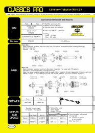
COSMIC ® CARBONE PRO<br />
CROSSRIDE<br />
DEETRAKS<br />
DEEMAX ® 4>21.<br />
4.<br />
5.<br />
6.<br />
7.<br />
8.<br />
9.<br />
10.<br />
11.<br />
12.<br />
13.<br />
12X150<br />
14. INDEXATION COMPATIBILITY OF ROAD WHEELS<br />
15. WHEEL MAINTENANCE<br />
16. HUB MAINTENANCE<br />
17>21. WHEEL BUILDING / REPLACING SPOKES AND RIMS<br />
MAVIC ® 22>27. RIMS<br />
22. SEGMENTATION OF THE RANGE<br />
23. GENERAL POINTS<br />
24. NEW 2006 RIMS<br />
25>26. WEAR INDICATOR / CONDITIONS FOR USING A RIM<br />
27. SPECIAL CONDITIONS FOR USING AND BUILDING A UST TUBELESS RIM<br />
28>35. SYSTEMS AND ACCESSORIES<br />
29. M-TECH.5 / M-TECH.7 / M-TECH.9<br />
30>35. PROGRAMMING / USE / INSTALLATION<br />
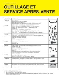
TOOLS AND CUSTOMER SERVICE<br />
MAVIC ® TOOLS<br />
GENERAL PROCEDURE FOR ANY REQUEST FOR INTERVENTION<br />
WARRANTY AND MAVIC ® 36>39.<br />
36>37.<br />
38.<br />
39.<br />
CUSTOMER SERVICE / TO CONTACT YOUR MSC<br />
THIS DOCUMENT ONLY CONCERNS THE NEW PRODUCTS IN 2006.<br />
THIS DOCUMENT UPDATES THE EXISTING TECHNICAL INFORMATION AND SHOULD THEREFORE BE KEPT IN A SAFE PLACE FOR AN UNLIMITED LENGTH OF TIME<br />
ALONG WITH THE MANUALS FROM PREVIOUS YEARS.<br />
ALL THE INFORMATION CONCERNING THE EXISTING PRODUCTS IN THE PREVIOUS RANGES CAN BE FOUND IN THE TECHNICAL MANUALS PRINTED SINCE 1997.<br />
YOU CAN GO ON-LINE TO THE WEBSITE www.<strong>tech</strong>-<strong>mavic</strong>.com TO FIND ALL THE EDITIONS OF THIS MANUAL SINCE 1997.
THE NEW 2006 TECHNICAL MANUAL<br />
THE 2006 TECHNICAL MANUAL IS ESSENTIAL FOR ENSURING THE MAINTENANCE OF MAVIC PRODUCTS.<br />
IT CONSISTS OF 4 MAIN PARTS:<br />
wheels<br />
rims<br />
components<br />
tools and customer service<br />
You will find two types of <strong>tech</strong>nical information in each of these parts:<br />
Product drawings showing individual part numbers;<br />
Procedures to properly maintain our products as well as those to follow concerning the warranty and Mavic<br />
Service Center.<br />
As we have already mentioned, this document only offers <strong>tech</strong>nical information regarding the modifications of the<br />
existing products and new products in the 2006 range. Therefore, it concerns:<br />
MAVIC CUSTOMER SERVICE<br />
CUSTOMER RETAILER<br />
MSC<br />
Our objective is that you be the only service<br />
partner for the consumer.<br />
You are also assured that through the use of<br />
our worldwide Mavic Service Center (MSC),<br />
you will benefit from maximum assistance,<br />
the best possible service and professional<br />
advice.<br />
Mavic MSC will be at your disposal to guide<br />
you through the necessary procedures in the<br />
event you need to return a part, make repairs,<br />
make standard replacements, or to send you<br />
spare parts needed for product maintenance.<br />
We simply ask that you contact your MSC<br />
prior to all returns (see page 39), to obtain<br />
the proper return procedures. Mavic will only<br />
accept authorized returns.<br />
For additional information, contact your MSC<br />
or consult the end pages of this <strong>tech</strong>nical<br />
manual.<br />
www.<strong>tech</strong>-<strong>mavic</strong>.com<br />
The wheels: Aksium, Ksyrium Equipe 06, Ksyrium Elite Black,<br />
Ksyrium SL 06, Ksyrium ES, Cosmic ® Carbone Pro,<br />
Crossride, Deetraks, Deemax ® 12x150.<br />
The rims: Open Sport, A 719, A 319, A 317 Disc, A 119*.<br />
The components: M-Tech.5, M-Tech.7, M-Tech.9, WIN-Tech ®<br />
2d bike kit, WIN-Tech ® handlebar support kit.<br />
We hope this document will meet your needs and we are always<br />
open to listen to any suggestions to improve on it.<br />
Thank you for your confidence in us and have a good 2006<br />
season.<br />
*OEM product only.<br />
TECHNICALMANUAL06<br />
This website is at your complete disposal. Every bit of information about Mavic<br />
products released since 1997 is available in PDF format both in English and French.<br />
Visit: www.<strong>tech</strong>-<strong>mavic</strong>.com where you will find all of this information. To connect to<br />
this website you will need a code and password. These codes will be communicated<br />
by your usual contacts: reps, sales assistants, Customer service, Mavic Service<br />
Center…<br />
Among other things on the site, you will find:<br />
All the <strong>tech</strong>nical details on all the Mavic products on the market since 1997 - wheels,<br />
rims, components – organised by discipline and by product;<br />
4 recap charts of spoke lengths and references on all our wheels, which will help<br />
you to better manage your spoke stock;<br />
A program for calculating spoke length: starting with a given Mavic rim, select<br />
the drilling and lacing pattern, the width of your hub, as well as the diameter of<br />
the flanges and the distance between the flanges and the frame support or fork;<br />
the spoke length required for building your wheel will<br />
automatically be calculated.<br />
We hope that this tool will meet your needs. Do not<br />
hesitate to inform us of any possible malfunction or<br />
improvements that you would like us to make.<br />
03<br />
INTRODUCTION
04<br />
TECHNICALMANUAL06<br />
MAVIC®<br />
TRACK<br />
iO<br />
COMETE<br />
TRACK<br />
ELLIPSE<br />
AERODYNAMIC<br />
COMETE ROAD<br />
COSMIC<br />
CARBONE PRO<br />
NEW<br />
COSMIC<br />
CARBONE SL<br />
COSMIC ELITE<br />
WHEELS<br />
SEGMENTATION OF THE 2006 WHEEL RANGE<br />
ROAD & TRIATHLON<br />
MULTI<br />
PERFORMANCE<br />
KSYRIUM ES<br />
NEW<br />
KSYRIUM SL<br />
NEW<br />
KSYRIUM ELITE<br />
NEW<br />
KSYRIUM ELITE 650<br />
KSYRIUM EQUIPE<br />
NEW<br />
AKSIUM<br />
NEW<br />
GENERAL POINTS<br />
CLASSIC<br />
COSMOS<br />
ASPHALT<br />
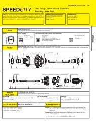
SPEEDCITY<br />
+ CL<br />
CROSS COUNTRY<br />
RACING<br />
CROSSMAX<br />
SL DISC LEFTY<br />
CROSSMAX SL<br />
DISC + CL<br />
CROSSMAX SL<br />
CROSS<br />
MOUNTAIN<br />
CROSSMAX XL<br />
DISC<br />
CROSSMAX XL<br />
CROSSMAX ENDURO DISC + CL<br />
CROSSMAX ENDURO<br />
CROSSLAND + CL<br />
CROSSRIDE<br />
Dear dealers, we would like to remind you that it is your responsibility to give the customer all wheel instructions and have them fill out the warranty<br />
guide.<br />
It is also your responsibility to provide the customer with the following recommended Mavic wheel instructions:<br />
Choose a suitable wheel designed for the type of riding you wish to do;<br />
It is imperative to respect the instructions in the Technical Manual for tire pressure and sizes (see charts page 14);<br />
Respect the appropriate spoke tensions.<br />
Clean the rims on a regular basis with the Mavic soft stone (M40410);<br />
Remove stones and metal particles from the brake pads;<br />
Replace the brake pads when they are worn;<br />
Do not use a rim if the braking surfaces are worn, if eyelets are missing, or in any other case where safety might be compromised. The rim is a part that<br />
wears out as do brake pads, and must be replaced if it is worn (sidewall hollowed by wear, or cut out, cracked rim…);<br />
Check or have your rims checked on a regular basis, at least at the start of each season and if possible after intensive use should you have a doubt about<br />
spoke tensions or the type of tire used. When checking, look inside (especially under the rim tape) and outside the rim. Check for signs of fatigue or wear:<br />
deterioration of braking surfaces, cracks in the sidewalls or around the eyelets.<br />
Following these recommendations will guarantee longer product life for the wheels, maximum performance and riding enjoyment.<br />
NEW<br />
<strong>MT</strong>B<br />
EXTREME <strong>MT</strong>B<br />
DEEMAX UST<br />
DEEMAX 12x150<br />
NEW<br />
DEETRAKS<br />
NEW
AKSIUM<br />
USE: use only on a road bike. Any other use (such as<br />
on a tandem, cyclo-cross bike, mountain bike...) is<br />
strongly inadvisable, is the sole responsibility of the<br />
user and voids the Mavic warranty.<br />
WIDTH<br />
21<br />
RIMS<br />
20,2<br />
HUBS<br />
9,5<br />
WHEEL<br />
BUILDING<br />
323 484 <strong>01</strong><br />
FEATURES:<br />
Silver or black, profiled, stainless steel, straight pull<br />
spokes with ABS nipples (self-locking)<br />
M40318<br />
323 482 <strong>01</strong><br />
323 479 <strong>01</strong><br />
324 484 <strong>01</strong><br />
M40660<br />
ACCESSORIES WHEEL DELIVERED WITH:<br />
MAINTENANCE<br />
M40578 995 000 <strong>01</strong> M40067<br />
REFERENCES AND LENGTHS: Black front: 324 192 <strong>01</strong>, length 278 mm (per 10 with nipples)<br />
Black rear: 324 193 <strong>01</strong>, length 302 mm (per 12 with nipples)<br />
Silver front: 324 190 <strong>01</strong>, length 278 mm (per 10 with nipples)<br />
Silver rear: 324 191 <strong>01</strong>, length 302 mm (per 12 with nipples)<br />
Traditional aluminium front quick release skewer M40350<br />
Traditional aluminum rear quick release skewer M40351<br />
ED10 12D locking ring (M40640) with rear wheel<br />
Rim tape 622x18x0.6<br />
User guide and warranty card<br />
WHEEL WEIGHTS WITHOUT<br />
QUICK RELEASE SKEWER:<br />
Front: 920 g<br />
Rear M10: 1075 g<br />
Rear ED10: 1060 g<br />
LACING PATTERN:<br />
Front: radial<br />
Rear: crossed 2 on both sides<br />
BLACK WHEEL<br />
REFERENCES:<br />
Front: 323 992 10<br />
Rear M10: 323 993 11<br />
Rear ED10: 323 994 12<br />
Pair M10 : 324 071 14<br />
Pair ED10: 324 072 14<br />
SALES REFERENCES:<br />
Black: Front: 324 177 10 Silver: Front: 324 176 10<br />
Rear: 324 177 13 Rear: 324 176 13<br />
VALVE HOLE Ø<br />
RECOMMENDED TIRE WIDTH AND PRESSURE<br />
Ø: 6,5 mm<br />
Length.: ≥ 32 mm<br />
MAINTENANCE: clean with dry cloth or soap and water<br />
Do not use pressurized water<br />
Dimensions:<br />
Ø 700 only<br />
ETRTO 622 x 15 compatible<br />
Recommended tire width: 19 to 32<br />
TECHNICALMANUAL06<br />
M40592 (M10)<br />
M40591 (ED10)<br />
TENSION:<br />
Front: 75 to 90 kg<br />
Rear free wheel side: 130 to 160 kg<br />
SILVER WHEEL<br />
REFERENCES:<br />
Front: 323 980 10<br />
Rear M10: 323 981 11<br />
Rear ED10: 323 982 12<br />
Pair M10: 324 064 14<br />
Pair ED10: 324 065 14<br />
Recommended tire<br />
pressure: See page 14<br />
Replacement of a front wheel spoke or rim See page 17<br />
For all other maintenance procedures (hubs, spoke lacing...),<br />
refer to the 2004 <strong>tech</strong>nical manual (Ksyrium Equipe section) or consult the website<br />
www.<strong>tech</strong>-<strong>mavic</strong>.com<br />
05<br />
WHEELS
06<br />
TM<br />
KSYRIUM<br />
USE: use only on a road bike. Any other use (such as<br />
on a tandem, cyclo-cross bike, or off-road use...) is<br />
strongly inadvisable, is the sole responsibility of the<br />
user and voids the Mavic warranty.<br />
WIDTH<br />
TECHNICALMANUAL06<br />
24<br />
RIMS<br />
19<br />
HUBS<br />
10<br />
WHEEL<br />
BUILDING<br />
323 484 <strong>01</strong><br />
FEATURES:<br />
Silver or black, profiled, stainless steel, straight pull<br />
spokes with ABS nipples (self-locking)<br />
323 487 <strong>01</strong><br />
323 484 <strong>01</strong> 323 484 <strong>01</strong><br />
323 479 <strong>01</strong><br />
323 482 <strong>01</strong><br />
M40660<br />
M40318<br />
M40578 995 000 <strong>01</strong><br />
ACCESSORIES WHEEL DELIVERED WITH:<br />
MAINTENANCE<br />
M40067<br />
REFERENCES AND LENGTHS: Black front: 324 186 <strong>01</strong>, length 284 mm (per 10 with nipples)<br />
Black rear: 324 187 <strong>01</strong>, length 300 mm (per 12 with nipples)<br />
Silver front: 324 188 <strong>01</strong>, length 284 mm (per 10 with nipples)<br />
Silver rear: 324 189 <strong>01</strong>, length 300 mm (per 12 with nipples)<br />
Traditional aluminum front quick release skewer M40350<br />
Traditional aluminum rear quick release skewer M40351<br />
ED10 12D locking ring M40640 (with rear wheel)<br />
Rim tape 622x18x0.6<br />
User guide and warranty card<br />
EQUIPE<br />
WHEEL WEIGHTS WITHOUT<br />
QUICK RELEASE SKEWER:<br />
Front: 845 g<br />
Rear M10 : 1<strong>01</strong>0 g<br />
Rear ED10 : 995 g<br />
MAINTENANCE: clean with dry cloth or soap and water<br />
Do not use pressurized water<br />
LACING PATTERN:<br />
Front: radial<br />
Rear: crossed 2 on both sides<br />
BLACK WHEEL<br />
REFERENCES:<br />
Front: 324 041 10<br />
Rear M10: 324 042 11<br />
Rear ED10: 324 043 12<br />
Pair M10: 324 047 14<br />
Pair ED10: 324 048 14<br />
SALES REFERENCES:<br />
Black: Front: 324 174 10 Silver: Front: 324 175 10<br />
Rear: 324 174 13 Rear: 324 175 13<br />
VALVE HOLE Ø<br />
RECOMMENDED TIRE WIDTH AND PRESSURE<br />
Ø: 6,5 mm<br />
Length.: ≥ 32 mm<br />
Dimensions :<br />
Ø 700 only<br />
ETRTO 622 x 13 compatible<br />
Recommended tire width: 19 to 28<br />
M40591 (ED10)<br />
M40592 (M10)<br />
TENSION :<br />
Front: 75 to 100 kg<br />
Rear free wheel side: 130 to 160 kg<br />
SILVER WHEEL<br />
REFERENCES:<br />
Front: 324 051 10<br />
Rear M10: 324 052 11<br />
Rear ED10: 324 053 12<br />
Pair M10: 324 057 14<br />
Pair ED10: 324 058 14<br />
Recommended tire<br />
pressure: See page 14<br />
For all maintenance procedures (hubs, spoke lacing...), refer to the 2004 <strong>tech</strong>nical<br />
manual or consult the website www.<strong>tech</strong>-<strong>mavic</strong>.com
TM<br />
KSYRIUM<br />
USE: use only on a road bike. Any other use (such as<br />
on a tandem, cyclo-cross bike, or off-road use...) is<br />
strongly inadvisable, is the sole responsibility of the<br />
user and voids the Mavic warranty.<br />
WIDTH<br />
25<br />
RIMS<br />
19<br />
HUBS<br />
10<br />
M40563 M40242<br />
WHEEL<br />
BUILDING<br />
FEATURES:<br />
Silver or black, ultra bladed, stainless steel, straight<br />
pull spokes with integrated M7 nipples (self-locking)<br />
M40242<br />
M40318<br />
M40243<br />
M40052<br />
M40063<br />
M40660<br />
M40589<br />
ACCESSORIES WHEEL DELIVERED WITH:<br />
MAINTENANCE<br />
M40578 995 000 <strong>01</strong><br />
M40067<br />
REFERENCES AND LENGTHS: Black front: 324 184 <strong>01</strong>, length 287 mm (per 9, integrated nipples)<br />
Black rear: 324 185 <strong>01</strong>, length 307 mm (per 10, integrated nipples)<br />
Silver front: 323 898 <strong>01</strong>, length 287 mm (per 9, integrated nipples)<br />
Silver rear: 323 899 <strong>01</strong>, length 307 mm (per 10, integrated nipples)<br />
Traditional aluminum front quick release skewer M40350<br />
Traditional aluminum rear quick release skewer M40351<br />
M7 spoke wrench M40494 (with rear wheel)<br />
Wrench for aerodynamic spokes M40567 (with rear wheel)<br />
ED10 12D locking ring (with rear wheel ED10)<br />
Free play adjustment wrench M4<strong>01</strong>23 (with rear wheel)<br />
User guide and warranty card<br />
ELITE 700<br />
WHEEL WEIGHTS WITHOUT<br />
QUICK RELEASE SKEWER:<br />
Front: 775 g<br />
Rear M10: 975 g<br />
Rear ED10: 960 g<br />
LACING PATTERN:<br />
Front: radial<br />
Rear: crossed 2 on both sides<br />
BLACK WHEEL<br />
REFERENCES:<br />
Front: 324 <strong>01</strong>3 10<br />
Rear M10: 324 <strong>01</strong>4 11<br />
Rear ED10: 324 <strong>01</strong>5 12<br />
Pair M10: 324 107 14<br />
Pair ED10: 324 108 14<br />
SALES REFERENCES:<br />
Black: Front: 324 173 10 Silver: Front: 323 911 10<br />
Rear: 324 173 13 Rear: 323 911 13<br />
VALVE HOLE Ø<br />
RECOMMENDED TIRE WIDTH AND PRESSURE<br />
Ø: 6,5 mm<br />
Length.: ≥ 32 mm<br />
Dimensions:<br />
Ø 700 only<br />
ETRTO 622 x 13 compatible<br />
Recommended tire width: 19 to 28<br />
When replacing the rear rim:<br />
1. With the valve hole near you, the 2 raised indicator bumps must be to the right of the valve hole<br />
2. The spoke in the first hole to the right of the valve hole should be inserted on the free wheel side<br />
MAINTENANCE: clean with dry cloth or soap and water<br />
Do not use pressurized water<br />
TECHNICALMANUAL06<br />
M40591 (ED10)<br />
M40592 (M10)<br />
TENSION :<br />
Front: 115 to 135 kg<br />
Rear free wheel side: 140 to 165 kg<br />
SILVER WHEEL<br />
REFERENCES:<br />
Front: 323 625 10<br />
Rear M10: 323 626 11<br />
Rear ED10: 323 627 12<br />
Pair M10: 324 740 14<br />
Pair ED10: 324 739 14<br />
Recommended tire<br />
pressure: See page 14<br />
For all maintenance procedures (hubs, spoke lacing...), refer to the 2002 <strong>tech</strong>nical<br />
manual (hubs) and 2005 <strong>tech</strong>nical manual (spoke lacing), or consult the website<br />
www.<strong>tech</strong>-<strong>mavic</strong>.com<br />
07<br />
WHEELS
08<br />
TM<br />
KSYRIUM<br />
USE: use only on a road bike. Any other use (such as<br />
on a tandem, cyclo-cross bike, or off-road use...) is<br />
strongly inadvisable, is the sole responsibility of the<br />
user and voids the Mavic warranty.<br />
WIDTH<br />
TECHNICALMANUAL06<br />
25<br />
RIMS<br />
19<br />
HUBS<br />
M40676<br />
10<br />
WHEEL<br />
BUILDING<br />
M40667<br />
FEATURES:<br />
Silver, profiled, Zicral, straight pull spokes with<br />
integrated M7 nipples (self-locking)<br />
M40052<br />
M40075<br />
M40063<br />
M40078<br />
M40759<br />
M40467 M40578 324 303 <strong>01</strong> M40067 324 130 <strong>01</strong><br />
324 303 <strong>01</strong><br />
ACCESSORIES WHEEL DELIVERED WITH:<br />
MAINTENANCE<br />
M40075<br />
M40591 (ED10)<br />
M40592 (M10)<br />
REFERENCES AND LENGTHS: Front: 324 181 <strong>01</strong>, length 281.5 mm (per 9, integrated nipples)<br />
Rear free wheel side: 324 182 <strong>01</strong>, length 272.2 mm (per 10, integrated nipples)<br />
Rear non drive side: 324 183 <strong>01</strong>, length 3<strong>01</strong>.5 mm (per 10, integrated nipples)<br />
BR 6<strong>01</strong> composite front quick release skewer M4<strong>01</strong>49<br />
BR 6<strong>01</strong> composite rear quick release skewer M4<strong>01</strong>50<br />
M7 spoke wrench M40652 (with rear wheel)<br />
Wrench for aerodynamic spokes M40567 (with rear wheel)<br />
Computer magnet (with front wheel)<br />
ED10 12D locking ring M40640 (with rear wheel ED10)<br />
Free play adjustment wrench<br />
User guide and warranty card<br />
SL 06<br />
WHEEL WEIGHTS WITHOUT<br />
QUICK RELEASE SKEWER:<br />
Clincher Tubular<br />
Front: 680 g 680 g<br />
Rear M10: 870 g 870 g<br />
Rear ED10: 855 g 855 g<br />
MAINTENANCE: clean with dry cloth or soap and water<br />
Do not use pressurized water<br />
LACING PATTERN:<br />
Front: radial<br />
Rear: Isopulse<br />
CLINCHER WHEEL<br />
REFERENCES:<br />
Front: 323 995 10<br />
Rear M10: 323 996 11<br />
Rear ED10: 323 997 12<br />
Pair M10: 324 032 14<br />
Pair ED10: 324 033 14<br />
SALES REFERENCES:<br />
Clincher: Front: 324 172 10 Tubular: Front: 324 305 10<br />
Rear: 324 172 13 Rear: 324 305 13<br />
VALVE HOLE Ø<br />
RECOMMENDED TIRE WIDTH AND PRESSURE<br />
Ø: 6,5 mm<br />
Length.: ≥ 32 mm<br />
Dimensions:<br />
Ø 700 only<br />
ETRTO 622 x 13 compatible<br />
Recommended tire width: 19 to 28<br />
When replacing the rear rim:<br />
1. With the valve hole near you, the 2 raised indicator bumps must be to the right of the valve hole<br />
2. The spoke in the first hole to the right of the valve hole should be inserted on the free wheel side<br />
Cleaning: If the rim becomes very dirty, a high pressure water jet may be used<br />
This must not under any circumstance be used on the other parts of the wheel<br />
TENSION :<br />
Front: 100 to 130 kg<br />
Rear free wheel side: 130 to 160 kg<br />
TUBULAR WHEEL<br />
REFERENCES:<br />
Front: 324 036 10<br />
Rear M10: 324 037 11<br />
Rear ED10: 324 038 12<br />
Pair M10: 324 039 14<br />
Pair ED10: 324 040 14<br />
Recommended tire<br />
pressure: See page 14<br />
For all maintenance procedures, refer to the 2002 <strong>tech</strong>nical manual (spoke lacing)<br />
and 2003 <strong>tech</strong>nical manual (hubs, Crossmax SL section), or consult the website<br />
www.<strong>tech</strong>-<strong>mavic</strong>.com
TM<br />
KSYRIUM<br />
USE: use only on a road bike. Any other use (such as<br />
on a tandem, cyclo-cross bike, or off-road use...) is<br />
strongly inadvisable, is the sole responsibility of the<br />
user and voids the Mavic warranty.<br />
WIDTH<br />
22<br />
19<br />
RIMS<br />
9<br />
M40676<br />
25<br />
19<br />
Front Back<br />
WHEEL<br />
BUILDING<br />
HUBS<br />
10<br />
324 194 <strong>01</strong><br />
FEATURES:<br />
Black, profiled, Zicral, straight pull spokes with<br />
integrated M7 nipples (self-locking)<br />
ES<br />
WHEEL WEIGHTS WITHOUT<br />
QUICK RELEASE SKEWER:<br />
Clincher Tubular<br />
Front: 645 g 630 g<br />
Rear M10: 855 g 855 g<br />
Rear ED10: 840 g 840 g<br />
M40078<br />
M40759<br />
M40075<br />
M40578<br />
CLINCHER WHEEL<br />
REFERENCES:<br />
Front: 324 0<strong>01</strong> 10<br />
Rear M10: 324 002 11<br />
Rear ED10: 324 003 12<br />
Pair M10: 324 023 14<br />
Pair ED10: 324 024 14<br />
SALES REFERENCES:<br />
Clincher: Front: 324 171 10 Tubular: Front: 324 304 10<br />
Rear: 324 171 13 Rear: 324 304 13<br />
VALVE HOLE Ø<br />
RECOMMENDED TIRE WIDTH AND PRESSURE<br />
Ø: 6,5 mm<br />
Length.: ≥ 32 mm<br />
Dimensions:<br />
Ø 700 only<br />
ETRTO 622 x 13 compatible<br />
Recommended tire width: 19 to 28<br />
M40063<br />
M40052<br />
995 000 <strong>01</strong> M40067<br />
M40591 (ED10)<br />
M40592 (M10)<br />
TUBULAR WHEEL<br />
REFERENCES:<br />
Front: 324 027 10<br />
Rear M10: 324 024 11<br />
Rear ED10: 324 025 12<br />
Pair M10: 324 030 14<br />
Pair ED10: 324 031 14<br />
324 130 <strong>01</strong><br />
09<br />
Recommended tire<br />
pressure:<br />
See page 14<br />
When replacing the rear rim:<br />
1. With the valve hole near you, the 2 raised indicator bumps must be to the right of the valve hole<br />
2. The spoke in the first hole to the right of the valve hole should be inserted on the free wheel side<br />
REFERENCES AND LENGTHS: Front: 324 178 <strong>01</strong>, length 284.5 mm (per 9, integrated nipples)<br />
Rear free wheel side: 324 179 <strong>01</strong>, length 275 mm (per 10, integrated nipples)<br />
Rear non drive side: 324 180 <strong>01</strong>, length 298.5 mm (per 10, integrated nipples)<br />
ACCESSORIES WHEEL DELIVERED WITH:<br />
MAINTENANCE<br />
BR 6<strong>01</strong> Titanium front quick release skewer 323 485 <strong>01</strong><br />
BR 6<strong>01</strong> Titanium rear quick release skewer 323 486 <strong>01</strong><br />
M7 spoke wrench M40494 (with rear wheel)<br />
Wrench for aerodynamic spokes M40567 (with rear wheel)<br />
Computer magnet M40540 (with front wheel)<br />
ED10 12D locking ring M40640 (with rear wheel ED10)<br />
Free play adjustment wrench M4<strong>01</strong>23<br />
Special Edition wheel bags User guide and warranty card<br />
MAINTENANCE: clean with dry cloth or soap and water<br />
Do not use pressurized water<br />
LACING PATTERN:<br />
Front: radial<br />
Rear: Isopulse<br />
TECHNICALMANUAL06<br />
TENSION :<br />
Front: 100 to 130 kg<br />
Rear free wheel side: 130 to 160 kg<br />
Replacing the rear rim See page 17<br />
For all other maintenance procedures, refer to the 2002 <strong>tech</strong>nical manual (spoke<br />
lacing, Ksyrium SL section) and 2003 <strong>tech</strong>nical manual (hubs, Crossmax SL<br />
section), or consult the website www.<strong>tech</strong>-<strong>mavic</strong>.com<br />
WHEELS
<strong>01</strong>0<br />
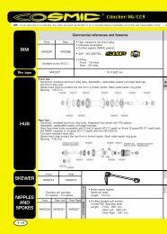
COSMIC CARBONE PRO<br />
USE: use only on a road bike. Any other use (such as on a tandem,<br />
cyclo-cross bike, or off-road use...) is strongly inadvisable, is the sole<br />
responsibility of the user and voids the Mavic warranty.<br />
WIDTH<br />
TECHNICALMANUAL06<br />
51,8<br />
RIMS<br />
21<br />
HUBS<br />
M40676<br />
9,5<br />
WHEEL<br />
BUILDING<br />
SALES REFERENCES:<br />
Front: 323 851 10<br />
Rear: 323 851 13<br />
VALVE HOLE Ø<br />
Ø: 6,5 mm<br />
Length.: ≥ 32 mm<br />
M40052<br />
FEATURES:<br />
Black, ultra bladed, stainless steel, straight pull spokes<br />
with reversed nipples to be glued (see page 18)<br />
MAINTENANCE: clean with dry cloth or soap and water<br />
Do not use pressurized water<br />
WHEEL WEIGHTS WITHOUT<br />
QUICK RELEASE SKEWER:<br />
Front: 675 g<br />
Rear M10: 835 g<br />
Rear ED10: 850 g<br />
M40075<br />
324 303 <strong>01</strong><br />
M40578<br />
323 859 <strong>01</strong><br />
M40078<br />
M40759<br />
M40063<br />
995 000 <strong>01</strong><br />
ACCESSORIES WHEEL DELIVERED WITH:<br />
MAINTENANCE<br />
M40067<br />
WHEEL REFERENCES:<br />
Front: 323 684 10<br />
Rear M10: 323 685 11<br />
Rear ED10: 323 686 12<br />
Pair M10: 323 757 14<br />
Pair ED10: 323 758 14<br />
M40591 (ED10)<br />
323 476 <strong>01</strong> (M10)<br />
REFERENCES AND LENGTHS: Front: 323 900 <strong>01</strong>, length 271 mm (per 8 with nipples)<br />
Rear free wheel side: 323 9<strong>01</strong> <strong>01</strong>, length 289 mm (per 10 with nipples)<br />
Rear non drive side: 323 902 <strong>01</strong>, length 270 mm (per 10 with nipples)<br />
BR 6<strong>01</strong> Titanium front quick release skewer: 323 485 <strong>01</strong><br />
BR 6<strong>01</strong> Titanium rear quick release skewer: 323 486 <strong>01</strong><br />
Spoke wrench 323 908 <strong>01</strong> (with rear wheel)<br />
Wrench for aerodynamic spokes M40567 (with rear wheel)<br />
Computer magnet M40540 (with front wheel)<br />
ED10 12D locking ring M40640 (with rear wheel ED10)<br />
Free play adjustment wrench M4<strong>01</strong>23<br />
Wheel bags M4<strong>01</strong>35<br />
User guide and warranty card<br />
RECOMMENDED TIRE WIDTH AND PRESSURE<br />
Dimensions:<br />
Ø 700 only<br />
ETRTO 622 compatible, for tubular tires only<br />
Recommended tubular width: 19 to 22<br />
When replacing the rear rim:<br />
1. The “Made in France” label must be facing you, and the valve hole must be near you<br />
2. The spoke in the first hole to the right of the valve hole should be inserted on the free wheel side<br />
Gluing the tubular tire: Clean the rim tape using a cloth soaked in isopropyl alcohol (if unavailable, use acétone)<br />
Never scratch the carbon fiber, and don’t use a knife, screwdriver or emery cloth<br />
Let the first layer of glue dry for at least 24 hours before gluing the tubular tire<br />
LACING PATTERN:<br />
Front: radial<br />
Rear: crossed 2 free wheel side, radial non-drive side<br />
TENSION :<br />
Front: 110 to 140 kg<br />
Rear free wheel side: 140 to 165 kg<br />
Recommended tire<br />
pressure: See page 14<br />
Replacing a spoke See page 18<br />
Replacing the front rim See page 18<br />
Replacing the rear rim See page 19<br />
For all hub related maintenance procedures, refer to the 2005 <strong>tech</strong>nical manual<br />
(Cosmic Carbone SL section), or consult the website<br />
www.<strong>tech</strong>-<strong>mavic</strong>.com
CROSSRIDE<br />
USE: use only on a Cross Country or Cross<br />
Mountain <strong>MT</strong>B. Any other use (such as on a<br />
tandem, road bike, cyclo-cross bike...) is strongly<br />
inadvisable, is the sole responsibility of the user<br />
and voids the Mavic warranty.<br />
WIDTH<br />
17,5<br />
RIMS<br />
24<br />
HUBS<br />
WHEEL WEIGHTS<br />
WITHOUT QUICK<br />
RELEASE SKEWER:<br />
Front: 910 g<br />
Rear: 1060 g<br />
M40318<br />
323 479 <strong>01</strong><br />
323 484 <strong>01</strong><br />
323 484 <strong>01</strong> M40660<br />
WHEEL<br />
BUILDING<br />
9<br />
FEATURES:<br />
Silver or black, profiled, stainless steel, straight pull<br />
spokes with ABS nipples (self-locking)<br />
BLACK WHEEL REFERENCES:<br />
Front: 323 983 10<br />
Rear: 323 984 13<br />
Pair: 324 100 14<br />
SALES REFERENCES:<br />
Black (front and rear): 324 200 14 Silver (front and rear): 324 199 14<br />
VALVE HOLE Ø<br />
Ø: 8,5 mm<br />
Length.: ≥ 32 mm<br />
MAINTENANCE: clean with dry cloth or soap and water<br />
Do not use pressurized water<br />
323 480 <strong>01</strong><br />
ACCESSORIES WHEEL DELIVERED WITH:<br />
MAINTENANCE<br />
SILVER WHEEL REFERENCES:<br />
Front: 323 973 10<br />
Rear: 323 974 13<br />
Pair: 324 090 14<br />
324 303 <strong>01</strong> 995 000 <strong>01</strong> M40067<br />
REFERENCES AND LENGTHS: Black front and rear: 324 223 <strong>01</strong>, length 274 mm (per 10 with nipples)<br />
Silver front and rear: 324 222 <strong>01</strong>, length 274 mm (per 10 with nipples)<br />
Traditional aluminum front quick release skewer: M40350<br />
Traditional aluminum rear quick release skewer: M40351<br />
Rim tape 559x20x0.6<br />
User guide and warranty card<br />
RECOMMENDED TIRE WIDTH AND PRESSURE<br />
LACING PATTERN:<br />
Front: crossed 2 on both sides<br />
Rear: crossed 2 on both sides<br />
Dimensions:<br />
Ø 26’ only<br />
ETRTO 559 x 19 compatible<br />
Recommended tire width: 1.5 to 2.3<br />
TECHNICALMANUAL06<br />
TENSION :<br />
Front: 95 to 125 kg<br />
Rear free wheel side: 115 to 145 kg<br />
For all maintenance procedures, refer to the 2004 <strong>tech</strong>nical manual<br />
(Crossland section), or consult the website www.<strong>tech</strong>-<strong>mavic</strong>.com<br />
Recommended tire<br />
pressure: See page 14<br />
M40592<br />
<strong>01</strong>1<br />
WHEELS
<strong>01</strong>2<br />
WIDTH<br />
21,6<br />
TECHNICALMANUAL06<br />
DEETRAKS<br />
USE: use only on an <strong>MT</strong>B. Any other use (such as on a tandem, road<br />
bike, cyclo-cross bike...) is strongly inadvisable, is the sole responsibility<br />
of the user and voids the Mavic warranty.<br />
RIMS<br />
32<br />
HUBS<br />
WHEEL<br />
BUILDING<br />
SALES REFERENCES:<br />
Front and rear: 324 2<strong>01</strong> 14<br />
VALVE HOLE Ø<br />
323 885 <strong>01</strong><br />
FEATURES:<br />
Black, round, stainless steel, straight pull spokes with<br />
ABS nipples (self-locking)<br />
M40721<br />
M40660<br />
M40723<br />
M4<strong>01</strong>79<br />
M40724<br />
M40739<br />
324 303 <strong>01</strong><br />
ACCESSORIES WHEEL DELIVERED WITH:<br />
MAINTENANCE<br />
20 mm adapters M40723 (with front wheel)<br />
Fixing nuts M40740<br />
Rim tape 559x24x0.6 (324 195 <strong>01</strong> per 4)<br />
User guide and warranty card<br />
Ø: 8,5 mm<br />
Length.: ≥ 32 mm<br />
MAINTENANCE: clean with dry cloth or soap and water<br />
Do not use pressurized water<br />
RECOMMENDED TIRE WIDTH AND PRESSURE<br />
Dimensions:<br />
Ø 26’ only<br />
ETRTO 559 x 25 compatible<br />
Recommended tire width: 2.0 to 3.0<br />
995 000 <strong>01</strong><br />
REFERENCES AND LENGTHS: Front and rear: 324 224 <strong>01</strong>, length 272 mm (per 16 with nipples)<br />
LACING PATTERN:<br />
Front and rear: crossed 3 on both sides<br />
WHEEL WEIGHTS WITHOUT<br />
QUICK RELEASE SKEWER:<br />
Front: 1210 g<br />
Rear: 1425 g<br />
WHEEL REFERENCES:<br />
Front: 324 <strong>01</strong>1 10<br />
Rear M10: 324 <strong>01</strong>2 13<br />
Pair: 324 077 14<br />
M40067 M40580<br />
TENSION :<br />
Front: 100 to 145 kg<br />
Rear free wheel side: 115 to 155 kg<br />
Recommended tire<br />
pressure: See page 14<br />
Replacing the front rim See page 20<br />
Replacing the rear rim See page 21<br />
For all hub related maintenance procedures, refer to the 2003 <strong>tech</strong>nical manual<br />
(Deemax UST section), or consult the website www.<strong>tech</strong>-<strong>mavic</strong>.com
DEEMAX 12x150<br />
USE: use only on an <strong>MT</strong>B. Any other use (such as on a tandem, road<br />
bike, cyclo-cross bike...) is strongly inadvisable, is the sole responsibility<br />
of the user and voids the Mavic warranty.<br />
WIDTH<br />
23<br />
RIMS<br />
28,8<br />
HUBS<br />
WHEEL<br />
BUILDING<br />
SALES REFERENCES:<br />
Front: 323 857 10<br />
Rear: 324 202 14<br />
VALVE HOLE Ø<br />
FEATURES:<br />
Black, round, stainless steel, straight pull spokes with<br />
integrated M7 nipples (self-locking)<br />
M40721<br />
WHEEL WEIGHTS WITHOUT<br />
FIXING NUTS AND REAR AXLE:<br />
Front: 1120 g<br />
Rear: 1490 g<br />
M40723<br />
M4<strong>01</strong>79<br />
M40724<br />
M40722<br />
324 170 <strong>01</strong> 324 197 <strong>01</strong> 324 196 <strong>01</strong><br />
324 299 <strong>01</strong><br />
324 198 <strong>01</strong><br />
REFERENCES AND LENGTHS: Front: 323 894 <strong>01</strong>, length 278 mm (per 14, integrated nipples)<br />
Rear: 324 225 <strong>01</strong>, length 273 mm (per 16, integrated nipples)<br />
ACCESSORIES WHEEL DELIVERED WITH:<br />
MAINTENANCE<br />
20 mm adapters M40723 (with front wheel)<br />
9 mm fork support nut M40722 (with front wheel)<br />
Fixing nuts M40740<br />
User guide and warranty card<br />
Ø: 6.5 mm<br />
UST valve + Schrader<br />
adapter: M40495<br />
Length.: 32 mm<br />
MAINTENANCE: clean with dry cloth or soap and water<br />
Do not use pressurized water<br />
RECOMMENDED TIRE WIDTH AND PRESSURE<br />
LACING PATTERN:<br />
Front and rear: crossed 3 on both sides<br />
Dimensions:<br />
Ø 26’ only<br />
ETRTO 559 x 23 compatible<br />
Recommended tire width: 2.0 to 3.0<br />
When replacing the rear rim:<br />
1. With the valve hole near you, the 2 raised indicator bumps must be to the right of the valve hole<br />
2. The spoke in the first hole to the right of the valve hole should be inserted on the free wheel side<br />
TECHNICALMANUAL06<br />
WHEEL REFERENCES:<br />
Front: 323 691 10<br />
Rear: 324 114 13<br />
Pair: 324 127 14<br />
TENSION :<br />
Front: 100 to 145 kg<br />
Rear free wheel side: 115 to 155 kg<br />
Recommended tire<br />
pressure: See page 14<br />
Warning: when fitting or removing your rear wheel, the free wheel body is easily knocked out of position. Take care to ensure it<br />
remains in place<br />
Replacing the free wheel body and pawls See page 16<br />
Replacing the rear axle and bearings See page 16<br />
For all other maintenance procedures, refer to the 2005 <strong>tech</strong>nical manual<br />
(spoke lacing) and 2003 <strong>tech</strong>nical manual (front hub), or consult the website<br />
www.<strong>tech</strong>-<strong>mavic</strong>.com<br />
<strong>01</strong>3<br />
WHEELS
<strong>01</strong>4 TECHNICALMANUAL06<br />
INDEXATION COMPATIBILITY OF ROAD WHEELS<br />
SINCE 2004, ALL THE MAVIC ROAD WHEELS ARE OFFERED WITH THE FTS-L FREE WHEEL BODY DESIGN, AND ARE CONSEQUENTLY M10<br />
AND ED10 COMPATIBLE (YOU CHOOSE WHEN ORDERING THE WHEEL).<br />
Refer to the following chart to know which wheel and which cassette to use according to your transmission:<br />
Your transmission:<br />
Number of speeds:<br />
Mavic wheel to be used:<br />
M9 positioning spacer M40417*:<br />
Type of cassette to be used:<br />
Spacer<br />
Ref.:<br />
Color:<br />
8 9<br />
HG8<br />
SHIMANO CAMPAGNOLO<br />
M10 ED10 M10 ED10 M10 ED10 M10<br />
With<br />
HG9 M10**<br />
M40409<br />
8 9 10<br />
Without<br />
ED8 M10** ED9 M10** ED10 M10**<br />
M4<strong>01</strong>82<br />
Original Original Original Campagnolo<br />
Original<br />
Original<br />
* The M9 positioning spacer is also supplied with the M10 wheels and the gray spacer kit M40409. It must be:<br />
Kept for mounting with a Shimano 8, 9 or 10 speed transmission.<br />
Removed for mounting with a Campagnolo 8, 9 or 10 speed transmission.<br />
** To obtain information on the M10 cassette, refer to our website www.<strong>mavic</strong>.com, our retailer catalogue or to the user guide supplied with the cassette.<br />
SPECIAL CASE FOR THE SPEEDCITY WHEEL<br />
Gray<br />
Alu<br />
M4<strong>01</strong>81<br />
Since 2004, the Speedcity wheel is offered with M10 compatibility (in place of HG9 in 2003). It is, of course, supplied with the positioning spacer M40417.<br />
Consequently, it can be used with:<br />
the HG 8 or 9 speed cassettes, by keeping the M9 positioning spacer M40417;<br />
the M10 Mavic cassette with 8 (alu spacers), 9 (gray spacers) or 10 (yellow spacers) speeds, by removing the M9 positioning spacer M40417;<br />
Using the FTS-L <strong>tech</strong>nology since 2005, it is also possible to mount an ED10 free wheel body on a Speedcity wheel and therefore an ED9 or ED10 cassette.<br />
10<br />
HG10<br />
RECOMMENDED MAXIMUM TIRE PRESSURES FOR MAVIC WHEELS<br />
ROAD, TRIATHLON and ASPHALT*<br />
Tire width<br />
in mm<br />
19<br />
23<br />
25<br />
28<br />
32<br />
Maximum pressure<br />
(bars)<br />
10,0<br />
9,5<br />
9,0<br />
8,0<br />
7,0<br />
Maximum pressure<br />
(PSI)<br />
146<br />
138<br />
131<br />
117<br />
103<br />
CROSS COUNTRY and CROSS MOUNTAIN*<br />
Tire width<br />
in ” in mm<br />
1,50<br />
1,75<br />
1,85<br />
1,90<br />
1,95<br />
2,00<br />
2,10<br />
2,20<br />
2,30<br />
38<br />
45<br />
47<br />
48<br />
50<br />
51<br />
53<br />
56<br />
58<br />
Maximum pressure<br />
(bars)<br />
6,00<br />
5,20<br />
4,80<br />
4,70<br />
4,50<br />
4,30<br />
4,00<br />
3,70<br />
3,30<br />
Maximum pressure<br />
(PSI)<br />
88<br />
76<br />
71<br />
69<br />
66<br />
63<br />
59<br />
55<br />
49<br />
EXTREME <strong>MT</strong>B*<br />
Tire width<br />
in ” in mm<br />
2,10<br />
2,20<br />
2,30<br />
2,40<br />
2,50<br />
2,60<br />
2,70<br />
2,80<br />
2,90<br />
3,00<br />
53<br />
56<br />
58<br />
61<br />
63<br />
66<br />
69<br />
71<br />
74<br />
76<br />
Yellow<br />
Maximum pressure<br />
(bars)<br />
3,70<br />
3,50<br />
3,30<br />
3,20<br />
3,00<br />
2,80<br />
2,70<br />
2,50<br />
2,40<br />
2,20<br />
M40573<br />
Black<br />
Maximum pressure<br />
(PSI)<br />
55<br />
52<br />
49<br />
47<br />
44<br />
41<br />
39<br />
36<br />
34<br />
32<br />
*See riding segmentation chart on page 4.
WHEEL MAINTENANCE<br />
REMINDER OF THE WARRANTY<br />
Before any repair of a Mavic wheel (or any other Mavic product), please note that it has a warranty against manufacturing or material defects for a period of 2 years from<br />
the date of original purchase by the original buyer (see Mavic warranty on page 39).<br />
This means that:<br />
During the warranty period, and when it definitely applies to the warranty (first contact your MSC), you must return the Mavic wheel (or any other Mavic product) directly<br />
to your MSC following the procedure explained on page 38 to get the Mavic warranty.<br />
However, if you decide to repair the wheel by yourself (or any other Mavic product), your customer will lose the Mavic warranty.<br />
After the warranty period and in case of repair, we advise you to refer to the following pages to intervene on the Mavic wheel. If replacing the rim, please note the new<br />
serial number of the rim on the original warranty card and the date of intervention.<br />
Only this procedure will allow your customer to get the Mavic warranty on the replaced rim.<br />
REPAIRS<br />
The following pages will help you to maintain the wheels in the 2006 range and are organized as follows:<br />
1. HUBS<br />
1.1. Deemax 12x150 free wheel body and pawl assemblies ................................................................................................................................................................................................................................. Page 16<br />
1.2. Deemax 12x150 rear axle and bearings ........................................................................................................................................................................................................................................................................ Page 16<br />
2. LACING .................................................................................................................................................................................................................................................................................................................................................. Pages 17 to 21<br />
2.1. Aksium wheel: replacing a front rim or spokes ..................................................................................................................................................................................................................................................... Page 17<br />
2.2. Ksyrium ES wheel: replacing a rear rim ........................................................................................................................................................................................................................................................................ Page 17<br />
2.3. Cosmic Carbone Pro wheels ................................................................................................................................................................................................................................................................................. Pages 18 to 19<br />
2.3.1. Replacing a spoke ......................................................................................................................................................................................................................................................................................................... Page 18<br />
2.3.2. Replacing a front rim ................................................................................................................................................................................................................................................................................................... Page 18<br />
2.3.3. Replacing a rear rim ..................................................................................................................................................................................................................................................................................................... Page 19<br />
2.4. Deetraks wheels ................................................................................................................................................................................................................................................................................................................ Pages 20 to 21<br />
2.4.1. Replacing a front rim ................................................................................................................................................................................................................................................................................................... Page 20<br />
2.4.2. Replacing a rear rim ..................................................................................................................................................................................................................................................................................................... Page 21<br />
All maintenance operations not detailed in the following pages can be found in the 2002, 2003 and 2004 <strong>tech</strong>nical manuals.<br />
Refer to the product sheets (pages 5 to 13 of this manual) for more details.<br />
Before any operation, we recommend removing:<br />
the wheel from the bike by releasing the quick release skewer<br />
the skewer, the tire<br />
the cassette and chain-disc (if necessary) for the rear wheel<br />
the brake disc (if necessary)<br />
TECHNICALMANUAL06<br />
<strong>01</strong>5<br />
WHEELS
<strong>01</strong>6<br />
TECHNICALMANUAL06<br />
1. HUBS<br />
1.1. DEEMAX 12x150 FREE WHEEL BODY AND PAWL ASSEMBLIES; DEEMAX 12x150 REAR AXLE<br />
Tools needed<br />
1 small flat screwdriver<br />
Unclip the fork support nut on the free<br />
wheel side.<br />
Delicately pull the right hand side<br />
of the spring and wind it around<br />
the pawl assemblies, ensuring it is<br />
correctly positioned at the bottom of<br />
the groove.<br />
Pull the free wheel body into the hub<br />
axle.<br />
Re-insert the free wheel body into the<br />
hub body by pivoting it anti-clockwise.<br />
1.2. DEEMAX 12x150 REAR AXLE AND BEARINGS<br />
Tools needed<br />
A mallet<br />
Bearing assembly tube 324 300 <strong>01</strong><br />
These operations can only be carried out with the free wheel body removed.<br />
Remove the plain bearing and the<br />
spacer by sliding them along the axle.<br />
Unclip the fork support nut on the non<br />
drive side and then hit the axle on the<br />
free wheel side with a mallet to remove<br />
the bearing from the non drive side.<br />
Repeat the operation for the free wheel<br />
side bearing.<br />
Refit the plain bearing and the spacer on the axle.<br />
Finish the operation by refitting the free wheel body and the fork support nuts as described in 1.1.<br />
Insert a small screwdriver under the<br />
pawl assembly at the right of the spring<br />
insertion hole and pull the spring to<br />
remove it from its housing.<br />
Re-clip the fork support nut.<br />
Refit the free wheel side bearing first<br />
using the assembly tube 324 300 <strong>01</strong>.<br />
Ensure the bearing is correctly seated<br />
in the hub body.<br />
Clean the free wheel body, grease the<br />
pawl assemblies and replace them in<br />
their housing. Insert the elbowed part<br />
of the spring into the insertion hole<br />
along the groove.<br />
Insert the axle from the non drive side<br />
and then refit the non drive side bearing<br />
using the assembly tube 324 300 <strong>01</strong>.
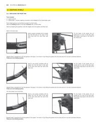
2. WHEEL BUILDING<br />
2.1. AKSIUM WHEEL: REPLACING A FRONT RIM OR SPOKE<br />
Tools needed<br />
1 traditional spoke wrench<br />
1 spoke wrench for aerodynamic spokes M40567<br />
1 tensiometer + tension-reading conversion chart adapted to the tensiometer used<br />
The reference and length of spokes to be used are given in the product pages (page 5).<br />
Prepare the spokes by screwing a<br />
nipple onto each spoke until it locks,<br />
then thread the spokes, elbow first,<br />
into each rim hole from the outside.<br />
Pass the elbowed part of each spoke<br />
through the slot in the hub flange.<br />
2.2. KSYRIUM ES WHEELS: REPLACING THE REAR RIM<br />
Tools needed<br />
1 spoke wrench M40652<br />
1 spoke wrench for aerodynamic spokes M40567<br />
1 tensiometer + tension-reading conversion chart adapted to the tensiometer used<br />
On the non drive side, the traction spokes locate into the notches of the most inside slots of the hub.<br />
The red spoke should be put at the free wheel side, in the 3rd hole to the right of the valve hole.<br />
Start with the free wheel side.<br />
Insert a 275 mm spoke (324 179 <strong>01</strong>)<br />
into a hole in the hub on the free wheel<br />
side from the inside of the flange. You<br />
must select a hole marked by a<br />
raised bump.<br />
Tighten the nipple of this spoke 2 turns<br />
into the 1st hole to the right of the<br />
valve hole (hole near to the raised<br />
bumps).<br />
Repeat these 2 operations for all the<br />
spokes on the free wheel side (1 hole<br />
in 2 in the rim).<br />
<strong>01</strong>7<br />
Re-tighten the spokes to the correct wheel tension ensuring that the head of each<br />
spoke is correctly positioned.<br />
Tighten the nipple of the 298.5 mm<br />
spokes (324 180 <strong>01</strong>) 2 turns into the<br />
remaining holes of the rim.<br />
As the holes in the rim are orientated,<br />
the fitted spokes are naturally<br />
positioned in the right direction.<br />
Tighten each nipple uniformely in the rim (1/2 turn of the spoke wrench for each spoke and per wheel rotation) to tension the wheel.<br />
Set the final tension and center the wheel(130 to 160 kg for spokes on the free wheel side).<br />
TECHNICALMANUAL06<br />
KO OK<br />
Now insert the spoke heads into the<br />
slots in the hub.<br />
WHEELS
<strong>01</strong>8<br />
TECHNICALMANUAL06<br />
2.3. COSMIC CARBONE PRO WHEELS<br />
2.3.1. REPLACING A SPOKE<br />
Tools needed<br />
1 spoke wrench 323 908 <strong>01</strong><br />
1 spoke wrench for aerodynamic spokes M40567<br />
Thread lock M40315<br />
1 tensiometer + tension-reading conversion chart adapted to the tensiometer used<br />
To replace a front spoke or a non drive side spoke, the wheel axle has to be removed. For details on how to do this, refer to the 2005 <strong>tech</strong>nical manual page 20 and the<br />
2003 <strong>tech</strong>nical manual page 19, or consult the website www.<strong>tech</strong>-<strong>mavic</strong>.com<br />
The tubular tire must also be removed.<br />
The nipples are inserted into the rim backwards: the round and wide side first.<br />
Insert the spoke wrench 323 908 <strong>01</strong><br />
in the rim hole to unscrew the spoke<br />
nipple.<br />
2.3.2. REPLACING THE FRONT RIM<br />
Place a 271 mm spoke (323 900 <strong>01</strong>)<br />
into a hole in the hub and insert its<br />
threaded part into a rim hole.<br />
Replace the new spoke into the hub<br />
and insert its threaded part into the<br />
rim hole.<br />
Position a nipple on the spoke wrench<br />
and stick it using thread lock M40315.<br />
Position a nipple on the spoke wrench<br />
and stick it using thread lock M40315.<br />
Insert the nipple and wrench into the<br />
rim hole and screw the nipple 2 turns<br />
onto the spoke.<br />
Insert the nipple and wrench into the<br />
rim hole and screw the nipple onto<br />
the spoke to re-tension and re-center<br />
the wheel.<br />
Tools needed<br />
1 spoke wrench 323 908 <strong>01</strong><br />
1 spoke wrench for aerodynamic spokes M40567<br />
Thread lock M40315<br />
1 tensiometer + tension-reading conversion chart adapted to the tensiometer used<br />
The wheel axle must be removed to replace the front rim. For details on how to do this, refer to the 2005 <strong>tech</strong>nical manual page 20, or consult the website<br />
www.<strong>tech</strong>-<strong>mavic</strong>.com<br />
Front wheel spokes must be fitted radially: they must not cross between the hub and the rim.<br />
The nipples are inserted into the rim backwards: the round and wide side first.<br />
Do the same for all the spokes on the same side of the hub (1 hole in 2 on the rim) and then for the other side of the hub, in the remaining holes in the rim.<br />
Tighten each nipple uniformely in the rim (1/2 turn of the spoke wrench for each spoke and per wheel rotation) to tension the wheel.<br />
Set the final tension and center the wheel(110 to 140 kg).
2.3.3. REPLACING THE REAR RIM<br />
Tools needed<br />
1 spoke wrench 323 908 <strong>01</strong><br />
1 spoke wrench for aerodynamic spokes M40567<br />
Thread lock M40315<br />
1 tensiometer + tension-reading conversion chart adapted to the tensiometer used<br />
The wheel axle must be removed to replace the rear rim. For details on how to do this, refer to the 2003 <strong>tech</strong>nical manual page 19, or consult the website<br />
www.<strong>tech</strong>-<strong>mavic</strong>.com<br />
Rear wheel spokes must be fitted:<br />
- radially on the non drive side: they must not cross between the hub and the rim<br />
- crossed 2 on the free wheel side, with the traction spokes located in the outside holes of the slots on the free wheel side.<br />
Note: the rim holes are orientated laterally and axially. As a consequence, the rim build order MUST be respected: with the «Made in France» label facing you, the<br />
spoke in the first hole to the right of the valve hole should be inserted on the free wheel side.<br />
The nipples are inserted into the rim backwards: the round and wide side first.<br />
Start with the free wheel side:<br />
Insert a 289 mm spoke (323 9<strong>01</strong> <strong>01</strong>)<br />
into an inside hole in the hub on the<br />
free wheel side, from the widest side<br />
of the hole.<br />
Insert its threaded part into the 1st hole<br />
to the right of the valve hole, with the<br />
«Made in France» label near you and<br />
facing you.<br />
Position a nipple on the spoke wrench<br />
and stick it using thread lock M40315.<br />
Insert the nipple and wrench into the<br />
rim hole and screw the nipple 2 turns<br />
onto the previously inserted spoke.<br />
Repeat these 3 operations:<br />
for all spokes in the inside holes on the free wheel side (1 hole in 4 on the rim). These are non-traction spokes.<br />
for all spokes in the outside holes on the free wheel side, starting with the 3rd hole to the right of the valve hole. These are traction spokes.<br />
Turn the wheel round, and then:<br />
Place a 270 mm spoke (323 902 <strong>01</strong>)<br />
into a hub hole on the non drive side.<br />
Insert its threaded part into the<br />
corresponding rim hole: the spokes go<br />
directly from the rim to the hub, without<br />
crossing each other.<br />
Position a nipple on the spoke wrench<br />
and stick it using thread lock M40315.<br />
Insert the nipple and wrench into the<br />
rim hole and screw the nipple 2 turns<br />
onto the previously inserted spoke.<br />
Repeat these 3 operations for all spokes on the non drive side.<br />
Then tighten each nipple uniformely in the rim (1 turn of the spoke wrench for each spoke and per wheel rotation) to tension the wheel.<br />
Set the final tension and center the wheel (140 to 165 kg).<br />
TECHNICALMANUAL06<br />
<strong>01</strong>9<br />
WHEELS
020<br />
TECHNICALMANUAL06<br />
2.4. DEETRAKS WHEELS<br />
2.4.1. REPLACING THE FRONT RIM<br />
Tools needed<br />
1 spoke wrench<br />
1 tensiometer + tension-reading conversion chart adapted to the tensiometer used<br />
Front wheel spokes must be fitted crossed 3 on both sides.<br />
Place the braking spokes in the slot’s external slits, on both sides.<br />
Start by preparing the spokes: screw the nipples onto the spokes until they lock.<br />
Start on the disc side:<br />
Insert a spoke complete with its nipple<br />
into the first hole to the right of the<br />
valve hole (with the valve hole near<br />
you).<br />
Repeat these 2 operations for all the spokes in this layer (1 rim hole in 4) by fitting the spokes into the slots and rim in an anti-clockwise direction.<br />
These are non-braking spokes.<br />
Insert a new spoke complete with its<br />
nipple into the 3rd hole to the right<br />
of the valve hole (with the valve hole<br />
near you).<br />
Repeat these 2 operations for all the spokes in this layer (1 rim hole in 4) by fitting the spokes into the slots and rim in an anti-clockwise direction.<br />
These are non-braking spokes.<br />
Turn the wheel round, and then:<br />
Insert a new spoke complete with its<br />
nipple into the 3rd hole to the right<br />
of the valve hole (with the valve hole<br />
near you).<br />
Repeat these 2 operations for all the spokes in this layer (1 rim hole in 4) by fitting the spokes into the slots and rim in an anti-clockwise direction.<br />
These are non-braking spokes.<br />
Fix the head of this spoke into an<br />
inside slit of a slot on the disc side.<br />
This spoke must pass to the right of<br />
the wheel axle.<br />
Fix the head of this spoke into an<br />
outside slit of a slot on the disc side.<br />
This spoke must pass to the left of the<br />
wheel axle.<br />
Fix the head of this spoke into an<br />
outside slit of a slot on the disc side.<br />
This spoke must pass to the left of the<br />
wheel axle.
Insert a new spoke complete with its<br />
nipple into the 1st hole to the right<br />
of the valve hole (with the valve hole<br />
near you).<br />
Repeat these 2 operations for all the spokes in this layer (1 rim hole in 4) by fitting the spokes into the slots and rim in an anti-clockwise direction.<br />
These are braking spokes.<br />
Then tighten each nipple uniformely in the rim (1 turn of the spoke wrench for each spoke and per wheel rotation) to tension the wheel.<br />
Set the final tension and center the wheel (100 to 145 kg).<br />
2.4.2. REPLACING THE REAR RIM<br />
Tools needed<br />
1 spoke wrench<br />
1 tensiometer + tension-reading conversion chart adapted to the tensiometer used<br />
Rear wheel spokes must be fitted crossed 3 on both sides:<br />
- free wheel side, the traction spokes are to be placed in the slots’ external holes;<br />
- non drive side, the traction spokes are to be placed in the slots’ internal holes;<br />
Start by preparing the spokes: screw the nipples onto the spokes until they lock.<br />
Start with the free wheel side:<br />
Insert a spoke complete with its nipple<br />
into the first hole to the right of the<br />
valve hole (with the valve hole near<br />
you).<br />
Repeat these 2 operations for all the spokes in this layer (1 rim hole in 4) by fitting the spokes into the slots in an anti-clockwise direction.<br />
These are non-traction spokes.<br />
Insert a new spoke complete with its<br />
nipple into the 3rd hole to the right<br />
of the valve hole (with the valve hole<br />
near you).<br />
Repeat these 2 operations for all the spokes in this layer (1 rim hole in 4) by fitting the spokes into the slots and rim in an anti-clockwise direction.<br />
These are traction spokes.<br />
Turn the wheel round and repeat all the operations described above in an identical manner for the non drive side:<br />
- the spokes of the 1st layer fitted must be traction spokes (inside slits of the slots);<br />
- the spokes of the 2nd layer fitted must be braking spokes (outside slits of the slots).<br />
Then tighten each nipple uniformely in the rim (1 turn of the spoke wrench for each spoke and per wheel rotation) to tension the wheel.<br />
Set the final tension and center the wheel (115 to 155 kg).<br />
TECHNICALMANUAL06<br />
021<br />
Fix the head of this spoke into an<br />
outside slit of a slot on the non disc<br />
side. This spoke must pass to the right<br />
of the wheel axle.<br />
Fix the head of this spoke into an<br />
inside slit of a slot on the free wheel<br />
side. This spoke must pass to the right<br />
of the wheel axle.<br />
Fix the head of this spoke into an<br />
outside slit of a slot on the free wheel<br />
side. This spoke must pass to the left<br />
of the wheel axle.<br />
WHEELS
022<br />
TECHNICALMANUAL06<br />
MAVIC®<br />
ROAD & TRIATHLON<br />
CLINCHER TUBULAR<br />
CLASSIC PROFILED CLASSIC<br />
OPEN PRO<br />
OPEN SPORT CXP22<br />
NEW<br />
* O.E.M. specific rims<br />
CXP33<br />
CXP23*<br />
RIMS<br />
SEGMENTATION OF THE RIM RANGE<br />
ASPHALT<br />
REFLEX A 719<br />
NEW<br />
A 319<br />
NEW<br />
A 317 DISC*<br />
NEW<br />
A 119*<br />
NEW<br />
CROSS COUNTRY<br />
RACING<br />
CROSS<br />
MOUNTAIN<br />
EXTREME <strong>MT</strong>B<br />
XC 717 DISC XM 819 DISC (UST) EX 823 DISC (UST)<br />
XC 717<br />
<strong>MT</strong>B<br />
XM 819 (UST)<br />
XM 719<br />
XM 517*<br />
XM 321 DISC<br />
XM 317 DISC*<br />
XM 317<br />
XM 117 DISC*<br />
XM 117*<br />
EX 729 DISC<br />
EX 721<br />
EX 325 DISC
GENERAL POINTS<br />
All the Mavic rims are based on these 4 principles:<br />
Aluminum alloy profile (6000 series) specified by Mavic;<br />
Double wall profile for greater strength and rigidity;<br />
Anodization for its corrosion resistance and aesthetic qualities while facilitating maintenance;<br />
The eyelet for better distribution of the pressure exerted by the spoke and increased strength and durability of the Mavic rim.<br />
The profiled eyelet (Mavic patent) combines the benefits of both the profiled rim and eyelet.<br />
WHAT’S NEW FOR 2006<br />
REMINDER OF THE NEW NAME FOR MAVIC <strong>MT</strong>B AND ASPHALT RIMS<br />
Mavic has identified 3 different types of <strong>MT</strong>B riding: Cross Country Racing, Cross Mountain and Extreme <strong>MT</strong>B. To clarify our <strong>MT</strong>B rim offer, we have decided<br />
to change their names.<br />
Since the trekking segment was baptized Asphalt, it seemed appropriate to have the name of our Asphalt rims evolve accordingly.<br />
Therefore:<br />
- the rims dedicated to Cross Country Racing have the prefix XC;<br />
- those dedicated to Cross Mountain riding have the prefix XM;<br />
- those dedicated to Extreme <strong>MT</strong>B have the prefix EX;<br />
- those dedicated to Asphalt have the prefix A;<br />
- the 1st digit indicates the level of the rim range. If this digit is even, the rim is UST Tubeless compatible;<br />
- the last 2 digits indicate its interior width (size in accordance with ETRTO standards);<br />
- the suffix Disc differentiates the rims that are compatible only with disc brakes from those that are not.<br />
Example: EX 325 Disc<br />
An intermediate (3) <strong>MT</strong>B Extreme (EX) rim, 25 mm wide (ETRTO: 559 x 25).<br />
<strong>MT</strong>B AND ASPHALT RIM VALVE ADAPTER<br />
All the valves holes in the <strong>MT</strong>B, Cross Country Racing, Cross Mountain (except the UST Tubeless) and now the Asphalt rims are drilled with an 8.5 mm diameter<br />
hole (Schrader valve). These rims are systematically fitted with a specific valve adapter which reduces the valve hole to a diameter of 6.5 mm, for use with a rim<br />
with an inner tube with a Presta type of valve.<br />
The special feature of this new valve adapter is that it automatically ejects when fitting a Schrader valve inner tube (Ø 8,5 mm) on to the rim.<br />
WHAT’S NEW IN THE 2006 RANGE<br />
A new rim profile makes its entry into the 2006 rim range:<br />
- Open Sport: a classic entry level road rim, strong and lightweight.<br />
TECHNICALMANUAL06<br />
And as for the Asphalt rims (A 719, A 317 Disc, A 319 and A 119), they now have a 8.5 mm valve hole and therefore a valve adapter to enable them to be fitted<br />
with an inner tube with a Presta valve (see above).<br />
023<br />
RIMS
024<br />
TECHNICALMANUAL06<br />
TECHNICAL FEATURES OF THE NEW 2006 RIMS<br />
Rim width<br />
Technologies<br />
Cantilever / V-Brake Disc<br />
OPEN SPORT A 719 A 319 A 119 A 317 Disc<br />
Material 6106 6106 6106 6106 6106<br />
8.5 delivered with 8.5 delivered with 8.5 delivered with 8.5 delivered with<br />
Valve hole diameter<br />
6,5 valve valve valve valve<br />
(in mm)<br />
adapter adapter adapter adapter<br />
ETRTO compatibility 622 x 15 622 x 19 622 x 19 622 x 19 622 x 17<br />
Recommended tire width<br />
(in mm)<br />
19 to 32 28 to 47 28 to 47 28 to 47 28 to 47<br />
Eyelets Single Double Double Single Double<br />
Average weight<br />
(in grams)<br />
490 567 597 540 538<br />
Finish Black 32, 36 32, 36, 40 32, 36 32, 36 -<br />
and drilling Silver 32, 36 36 32, 36 32, 36 32, 36<br />
Recommended spoke nipple<br />
length (in mm)<br />
Spoke support diameter<br />
(in mm)<br />
16<br />
ROAD ASPHALT<br />
20,2<br />
9,5<br />
10<br />
24,5<br />
12 12 12 12 12<br />
606 600 600 604 600<br />
Recommended rim tape<br />
(ETRTO x length x thickness) 622 x 18 x 0,6 622 x 20 x 0,6 622 x 20 x 0,6 622 x 20 x 0,6 622 x 20 x 0,6<br />
Wear indicator External Internal Internal External -<br />
The Mavic rims not mentioned in the above chart have not changed. Their <strong>tech</strong>nical features can therefore be found in previous years’ <strong>tech</strong>nical<br />
manuals or on the <strong>tech</strong>nical manual website: www.<strong>tech</strong>-<strong>mavic</strong>.com<br />
19,8<br />
19,5<br />
25<br />
9<br />
9<br />
24<br />
17,5<br />
23,5<br />
20
THE WEAR INDICATOR<br />
Mavic has chosen to provide certain of its rim profiles that have a braking surface with a wear indicator.<br />
2 types of wear indicator are used on our rims:<br />
INTERNAL:<br />
Process: The inside of the braking surface of the rim is machined on both of the wings of the rim.<br />
Principle:<br />
When there is too much wear on the rim, a little hole appears on each of the 2 braking surfaces of the rim. Depending on the adjustment of the brake pads, it is possible<br />
for the wear indicator to appear on only one of the 2 braking surfaces. In any case, the appearance of the wear indicator on at least one of the 2 braking surfaces<br />
means that the sidewalls are too thin, and it could be dangerous to continue to use the rim. It should be replaced as soon as possible.<br />
The position of the wear indicator is marked by 2 yellow arrows on the stickers on the rim, opposite the valve hole.<br />
Refer to the chart on the previous page to find out which rims offer this internal wear indicator.<br />
INTEGRATED IN THE PROFILE:<br />
Process: the wear indicator is an integral part of the rim. There is a groove on the entire circumference of the rim, at the center of the braking surfac<br />
Principe : The groove becomes more shallow as the braking wears down the surface of the rim. Its disappearance, on one side of the rim or the other, means that<br />
the thickness of the braking surface is too thin and it could be dangerous to continue to use the rim. It should be replaced as soon as possible.<br />
Refer to the chart on the previous page to find out which rims offer this integrated wear indicator.<br />
The Ceramic ® coating, by preventing the braking surfaces to become hollow, can be used as a wear indicator.<br />
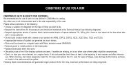
CONDITIONS OF USE FOR A RIM<br />
CONDITIONS OF USE TO BE GIVEN TO YOUR CUSTOMERS<br />
Mavic uses the most advanced <strong>tech</strong>nology in the design of its rims and wheels. However, a rim cannot last forever and wears down according to its use: type of riding,<br />
terrain, brake pad, spoke tension, tires, tire pressure, weather conditions, etc.<br />
Each rim has been designed for a specific use and discipline (road, cross-country, downhill, touring…). Any other use of a rim for which it has not been designed<br />
is highly inadvisable, the sole responsibility of the user and voids the Mavic warranty.<br />
Please advise your customers of the following points:<br />
Choose a suitable rim designed for the type of riding you wish to do: do not use cross-country rims on wheels that will be mounted on free-ride, downhill or dual<br />
bikes;<br />
You must follow the instructions in this <strong>tech</strong>nical manual for tire pressure and sizes (see charts on page 26);<br />
Respect the appropriate spoke tensions. Mavic recommends spoke tensions between 70 and 90 kg (for a front or rear wheel on the free wheel side with a crossed<br />
3 pattern). Inappropriate spoke tension can generate too much stress and damage the rim;<br />
Clean the rims on a regular basis with the Mavic soft stone (M40410);<br />
Remove stones and metal particles from the brake pads;<br />
Replace the brake pads when they are worn;<br />
Do not use a rim if the braking surfaces are worn, if eyelets are missing, or in any other case where safety might be compromised. The rim is a part that wears out<br />
as do brake pads, and must be replaced if it is worn (sidewall hollowed by wear, or cut out, cracked rim…) ;<br />
For rims fitted with a wear indicator (internal or external) do not continue to use the rim if the indicator appears (internal wear indicator) or disappears (external wear<br />
indicator) on at least one of the 2 braking surfaces;<br />
For rims not fitted with a wear indicator, check using a depth gauge that the maximum wear on each side is not more than 0.4 mm;<br />
Check or have your rims checked on a regular basis, at least at the start of each season and if possible after intensive use or if you have a doubt about spoke<br />
tension or the type of tire used. When checking, look inside (especially under the rim tape) and outside the rim. Check for signs of fatigue or wear: damage to braking<br />
surfaces, appearance or disappearance of the wear indicator (only on rims fitted with a wear indicator), cracks in the sidewalls or around the eyelets…<br />
Following these recommendations will guarantee longer product life for the rims, maximum performance and riding enjoyment.<br />
TECHNICALMANUAL06<br />
025<br />
RIMS
026<br />
TECHNICALMANUAL06<br />
RECOMMENDATION FOR MAXIMUM TIRE PRESSURE<br />
CROSS COUNTRY AND CROSS MOUNTAIN*<br />
Tire width<br />
in ” in mm<br />
1,00<br />
1,20<br />
1,50<br />
1,75<br />
1,85<br />
1,90<br />
1,95<br />
2,00<br />
2,10<br />
2,20<br />
2,30<br />
25<br />
30<br />
38<br />
45<br />
47<br />
48<br />
50<br />
51<br />
53<br />
56<br />
58<br />
ROAD & TRIATHLON*<br />
Tire width<br />
in mm<br />
19<br />
23<br />
25<br />
28<br />
32<br />
*See riding segmentation chart on page 22.<br />
DURABILITY<br />
A rim has 2 main functions: support the tire and serve as a brake disc.<br />
In the course of this second function as a braking surface, rims may be subject to wear, especially from intensive or prolonged use. Rims may experience wear for reasons<br />
as diverse as the build-up of gravel or mud in the brake pads or the use of worn or poorly adjusted brake pads. These can wear down or damage the rim sidewalls, and<br />
may not be noticed by the user.<br />
It is consequently common practise for the user to replace the rims as he would the brake pads. You must make your customers aware of this.<br />
To reduce wear, we have developed a Ceramic coating on our top-of-the-line rims.<br />
If the rim is heavily out of true following a violent shock, the rim should be replaced as soon as possible in order to avoid overloading or possibly broken spokes.<br />
MAINTENANCE<br />
Maximum pressure<br />
(bars)<br />
7,70<br />
7,00<br />
6,00<br />
5,20<br />
4,80<br />
4,70<br />
4,50<br />
4,30<br />
4,00<br />
3,70<br />
3,30<br />
Maximum pressure<br />
(bars)<br />
10,00<br />
9,50<br />
9,00<br />
8,00<br />
7,00<br />
Maximum pressure<br />
(PSI)<br />
113<br />
103<br />
88<br />
76<br />
71<br />
69<br />
66<br />
63<br />
59<br />
55<br />
49<br />
Maximum pressure<br />
(PSI)<br />
146<br />
138<br />
131<br />
117<br />
103<br />
EXTREME <strong>MT</strong>B*<br />
Tire width<br />
in ” in mm<br />
Rims and brake pads must be cleaned with soap and water on a regular basis. Abrasive substances (sand…) may have been deposited during use and could scratch or<br />
cause unnecessary damage to the sidewalls of rims.<br />
If cleaning is not sufficient on the braking surfaces, use a Mavic soft stone (M40410), except on rims designed specifically for disc brakes. Only use the Mavic soft stone,<br />
a sponge or a cloth.<br />
If there is still grease on the rim, it can be removed with any type of solvent without risking damage to the rim (except for the Deemax rim). However, do not use any<br />
solvents in the area of the sticker or tire, as there is risk of damage to these areas.<br />
2,10<br />
2,20<br />
2,30<br />
2,40<br />
2,50<br />
2,60<br />
2,70<br />
2,80<br />
2,90<br />
3,00<br />
ASPHALT*<br />
Tire width<br />
in mm<br />
28<br />
30<br />
32<br />
35<br />
37<br />
40<br />
44<br />
47<br />
50<br />
53<br />
56<br />
58<br />
61<br />
63<br />
66<br />
69<br />
71<br />
74<br />
76<br />
Maximum pressure<br />
(bars)<br />
3,70<br />
3,50<br />
3,30<br />
3,20<br />
3,00<br />
2,80<br />
2,70<br />
2,50<br />
2,40<br />
2,20<br />
Maximum pressure<br />
(bars)<br />
7,00<br />
7,00<br />
7,00<br />
6,00<br />
6,00<br />
5,60<br />
5,20<br />
4,80<br />
4,50<br />
Maximum pressure<br />
(PSI)<br />
55<br />
52<br />
49<br />
47<br />
44<br />
41<br />
39<br />
36<br />
34<br />
32<br />
Maximum pressure<br />
(PSI)<br />
103<br />
103<br />
103<br />
88<br />
88<br />
82<br />
76<br />
71<br />
66
SPECIAL CONDITIONS FOR USING A UST TM<br />
TUBELESS RIM<br />
MAKING SURE THE TUBELESS SYSTEM (UST TUBELESS RIM WITH A UST TUBELESS TIRE) IS AIRTIGHT<br />
We advise you to make sure that your UST Tubeless system (UST Tubeless rim or wheel combined with a UST Tubeless tire) is airtight in the following cases:<br />
- After building the UST Tubeless rim;<br />
- After fitting the UST Tubeless tire.<br />
If you are not sure the tubeless system is airtight, proceed in the following manner:<br />
Check the outside condition of the tire (cuts, any type of damage…).<br />
Make sure the tire is locked in place: inflate to 110% of the maximum pressure indicated on the tire and then completely deflate: the tire must stay locked in the rim.<br />
Make sure the inside of the tire and rim are clean (clean with a cloth if necessary).<br />
Check the condition of the heel of the tire and the wings on the rim.<br />
Wet the tire and rim abundantly with soap and water, and then fit the tire.<br />
Since the UST Tubeless unit is under 3 bars of pressure, immerse the base of the wheel mounted with its tire in a container or spray a leak detector on the rim/tire interface<br />
to find a possible leak. If there is a leak:<br />
- Between the rim and the tire: replace or repair the UST Tubeless tire with a repair patch, after having removed any grease from the tire with trichlorethylene or<br />
acetone.<br />
- Around the UST valve: Remove the valve, grease the rubber part that is in contact with the rim, and then refit it. If there is no improvement, replace the valve.<br />
- Around the hollow screws, spoke nipples or Zicral spoke nipples: replace the rim.<br />
Warning: The air contained between the 2 bridges of the rim will naturally have a tendency to escape because of the pressure of the water and could be the origin<br />
of air bubbles. Therefore, check this phenomena before replacing the rim.<br />
Fit another tire that you know is perfectly airtight.<br />
If there is a leak around the valve: Remove the valve, grease the rubber part that is in contact with the rim, and then refit it.<br />
If the tubeless system still isn’t airtight after following all these procedures, contact Mavic customer service or your MSC.<br />
USING A UST TUBELESS RIM WITH A CLASSIC TIRE AND A TUBE<br />
The ETRTO standard now integrates the tubeless concept. As a result, by respecting certain conditions of use, a UST rim can officially, and without risk, be<br />
combined with a classic tire and tube.<br />
The 3 main conditions for using a UST tubeless rim with a classic tire and tube are:<br />
Only use ETRTO compatible tires;<br />
Only use tubes with a Presta type of valve (Ø 6.5);<br />
Use a UST Tubeless WITHOUT rim tape (except for the rim on the Crossland wheel).<br />
TECHNICALMANUAL06<br />
Once the UST Tubeless valve has been removed, you can only insert a Presta type of tube (small valve, Ø 6.5 mm) into the valve hole of the UST Tubeless rim.<br />
Warning: Never try to make the valve hole bigger or drill it. If you do so, you could permanently damage the rim and would not be able to use the UST valve, which is necessary<br />
to keep the rim airtight.<br />
When fitting a classic tire on a UST Tubeless rim, follow the same procedure as when using a UST Tubeless tire. That is:<br />
1. Abundantly moisten the rim tape and tire beads with soap and water;<br />
2. Insert the first tire groove into the bottom of the rim groove;<br />
3. Place the Presta tube in the classic manner;<br />
4. Then fit the second bead by starting on the opposite side of the valve and finishing at the valve;<br />
5. Center the heels of the tire on both sides of the valve;<br />
6. Rotate the tire to make sure the beads are properly placed at the bottom of the rim groove;<br />
7. Inflate the tire energetically until the tire beads lock into place. The locking action can generate a series of short sounds due to the tire rising to its final position. Inflate up<br />
to 5 bars to be sure the tire is firmly in place. Being locked in place does not make the tire/rim system completely airtight, but it does guarantee that the tire is<br />
properly held in place. In this way, the tire will be properly placed in the rim groove and you can ride without risk of it rolling off the rim.<br />
8. Adjust the tire pressure to your type of riding and preference. Warning: When using a UST rim with a classic tire and tube, the adjustment of the pressure is not «without risk»,<br />
just like on an «all UST» assembly (tire + rim).<br />
027<br />
RIMS
028<br />
SYSTEMS<br />
TECHNICALMANUAL06<br />
COMPUTERS<br />
WIN-TECH ES<br />
WIN-TECH FS<br />
M-TECH.9<br />
NEW<br />
M-TECH.7<br />
NEW<br />
M-TECH.5<br />
NEW<br />
ELECTRONIC MECHANIC MISCELLANEOUS<br />
GENERAL POINTS<br />
ELECTRONIC<br />
ACCESSORIES<br />
PEDALING<br />
CADENCE KIT<br />
SENSOR KIT<br />
HOME TRAINER<br />
2ND BIKE KIT<br />
HANDLEBAR<br />
SUPPORT KIT<br />
M-TECH.<br />
MOUNTING KIT<br />
NEW<br />
BRAKES<br />
SSC BRAKES<br />
TRANSMISSION<br />
M10 CASSETTE KIT N°1<br />
M10 CASSETTE KIT N°2<br />
M10 CASSETTE KIT N°3<br />
M10 CASSETTE KIT N°4<br />
WHEEL<br />
ACCESSORIES<br />
QUICK RELEASE<br />
SKEWER BR 6<strong>01</strong><br />
QUICK RELEASE<br />
SKEWER BX 6<strong>01</strong><br />
SAINT ® DERAILLEUR<br />
AXLE KIT<br />
QUICK RELEASE<br />
AXLE KIT<br />
TRACK COG<br />
LOCK RING<br />
SPARE PART<br />
KITS<br />
REPLACEMENT KIT<br />
ROAD SPOKE KIT<br />
<strong>MT</strong>B SPOKE KIT<br />
ACCESSORIES<br />
ROAD WHEEL BAG<br />
<strong>MT</strong>B WHEEL BAG<br />
SOFT STONE<br />
UNIVERSAL MAGNET<br />
Dear dealers, we would like to remind you that it is your responsibility to give the customer all component instructions and have them fill out the<br />
warranty card.<br />
We also advise the users of Mavic components to follow the instructions below:<br />
Follow the conditions of use described at the top of each Mavic component product page (pages 29 to 35). Any other use outside of these conditions is inadvisable,<br />
the sole responsibility of the user and voids the Mavic warranty.<br />
Although water resistant, it is strongly inadvisable to use pressurized water on electronic and mechanical components.<br />
It is also inadvisable to use solvents and petroleum products to clean the various components. It is preferable to use warm water, or soap and water, and to dry with a<br />
cloth.<br />
Do not leave the liquid crystal WIN-Tech screens exposed to the sun (e.g. behind the windshield of your vehicle).<br />
Each of WIN-Tech’s electronic components has its own digital code. The synchronisation operation allows components of the same system to function with<br />
the same digital code and therefore be impenetrable to outside signals. This means that each component of a system cannot be used with the components<br />
of another system fitted to another bike (WIN <strong>tech</strong>nology).<br />
This synchronization operation is vital for the correct operation of the system. It must be carried out before using the system for the first time and each time<br />
one of the batteries is replaced.<br />
Following these recommendations will guarantee longer product life for the components, maximum performance and riding enjoyment.<br />
Biking is a sport which may require intense physical activity and as such poses a risk dependent on the route and the environment.<br />
For your own safety, keep an eye on the road and the traffic. Wear a helmet.
M-Tech.<br />
USE: Use only on a Cross Country or Cross Mountain <strong>MT</strong>B, a road<br />
bike, a tandem or an Asphalt type of bike. Any other use (such as on<br />
an Extreme <strong>MT</strong>B, cyclo-Cross bike…) is strongly inadvisable, is the<br />
sole responsibility of the user and voids the Mavic warranty.<br />
SPARE PARTS<br />
FUNCTIONING FEATURES<br />
Power supply: battery CR2032 (computer)<br />
Circumference: 1000 mm to 3999 mm<br />
Unit: kilometers or miles<br />
Time format: 12 or 24 hours (M-Tech.9 only)<br />
Water resistance: Resistant to rainwater. Avoid total immersion<br />
of the electronic components and do not use<br />
pressurized water<br />
INSTALLATION, USE AND PROGRAMMING<br />
WEIGHT:<br />
Computer: 26 g<br />
Computer bracket + wire + fork sensor: 18 g<br />
324 255 <strong>01</strong><br />
MAINTENANCE: clean with dry cloth or soap and water<br />
Do not use pressurized water<br />
Do not store near a window exposed to the sun for a long period of time<br />
TECHNICALMANUAL06<br />
Wire length: 88 cm (+/- 0,5 cm)<br />
Cumulative odometer: up to 99,999 km or miles<br />
Trip distance: up to 999.9 km or miles<br />
Stopwatch: up to 9:59:59<br />
Speed: up to 99.9 km/h or 70 miles/h<br />
REFERENCES:<br />
M-Tech.9: 323 989 <strong>01</strong><br />
M-Tech.7: 324 004 <strong>01</strong><br />
M-Tech.5: 324 006 <strong>01</strong><br />
Fitting the computer bracket See pages 34 to 35 Programming See pages 30 to 32<br />
Use See pages 32 to 33<br />
Installation See pages 34 to 35<br />
029<br />
SYSTEMS
030<br />
TECHNICALMANUAL06<br />
PROGRAMMING<br />
GENERAL OPERATION<br />
L (left) button: validate, delete, reset.<br />
R (right) button: start, stop, scroll values or functions.<br />
INITIALIZING THE COMPUTER<br />
Press both buttons simultaneously for 4 seconds, until all the segments of the LCD screen are displayed (the phases shown below are successively displayed).<br />
Release the buttons, the “SEL Km” screen appears. The computer is ready for the next step.<br />
SELECTING THE DISTANCE AND SPEED UNITS<br />
In the previous screen, press the R button to<br />
select Miles or Kilometers.<br />
Press the L button to validate.<br />
The “Cir” screen appears.<br />
Go to the next step.<br />
If the “SEL Km” screen is not displayed correctly, open and close the battery cover, making sure the battery is correctly positioned (see page 35).<br />
MEASURING THE WHEEL CIRCUMFERENCE<br />
Refer to the chart below for the approximate circumference of your wheel:<br />
TIRE<br />
26’’ x 1,5<br />
26’’ x 1,75<br />
26’’ x 1,9<br />
26’’ x 2,0<br />
26’’ x 2,1<br />
26’’ x 2,2<br />
26’’ x 2,3<br />
650C x 19<br />
650C x 23<br />
CIRCUM.<br />
2020<br />
2070<br />
2090<br />
2110<br />
2130<br />
2150<br />
2170<br />
1930<br />
1990<br />
TIRE<br />
700C x 19<br />
700C x 20<br />
700C x 23<br />
700C x 25<br />
700C x 28<br />
700C x 32<br />
700C x 35<br />
CIRCUM.<br />
2100<br />
2110<br />
2130<br />
2140<br />
2150<br />
2170<br />
2200
For a more accurate measurement, proceed as follows:<br />
- At the point of contact between the tire and the ground, mark both the tire and the ground.<br />
- Rotate the wheel one full turn and at the point where the mark on the tire next touches the ground, mark the ground again.<br />
- Measure the distance (D) between these two points in mm, and note this distance (D) for the next step.<br />
Minimum circumference: 1000 mm. Maximum circumference: 3999 mm.<br />
SETTING THE CIRCUMFERENCE<br />
Once the distance unit has been selected, the “Cir” screen is<br />
displayed. The default value is 2155 mm. The digit furthest to the left<br />
of the screen flashes. Scroll through the values using the R button<br />
until the desired value is reached.<br />
Validate using the L button.<br />
Displaying the stored circumference<br />
With the “ODO” screen displayed, press the L and R buttons<br />
simultaneously to display the stored circumference. This value is<br />
displayed for 3 seconds.<br />
Programming a new circumference<br />
With the «ODO» screen displayed, press the L and R buttons<br />
simultaneously, and then release them. The circumference is<br />
displayed.<br />
D<br />
The next digit then flashes. Carry out the same<br />
operation for each digit.<br />
Once the correct value has been entered, validate<br />
by pressing the L button.<br />
The “ODO” screen is displayed.<br />
Go to the next step.<br />
In the 3 seconds that follow, press the L and R buttons simultaneously<br />
again to display the “Cir” screen. You can now enter a new value by<br />
following the steps detailed above.<br />
Changing the circumference value does not reset the odometer to zero.<br />
It is thus possible to use two pairs of wheels with different diameters on the same bike, or to use your computer on two different bikes.<br />
TECHNICALMANUAL06<br />
031<br />
SYSTEMS
032<br />
USE<br />
TECHNICALMANUAL06<br />
SETTING THE TIME (M-TECH.9 ONLY)<br />
When in any screen, press the R button<br />
for 1 second to display the clock.<br />
Selecting 12 or 24 hour display<br />
Either a 12 or 24 hour display can be selected.<br />
When in the «clock» screen, keep the R button pressed<br />
down for 3 seconds to go from one display to the other.<br />
SCROLLING THROUGH THE FUNCTIONS<br />
Once the time is displayed, press the L and R buttons<br />
simultaneously for 2 seconds. The hours display flashes.<br />
Press the R button until the required value is reached.<br />
The computer screen is divided into two parts. The Current Speed is always displayed in the upper part of the screen (up to 99 km/h or 70 miles/h).<br />
The lower part of the screen is reserved for the other functions.<br />
Scrolling through the functions is achieved by briefly pressing the R button:<br />
- Odometer (ODO)<br />
- Trip Distance (DIS)<br />
- Average Speed (AV)<br />
- Stopwatch (rolling time) (RT)<br />
- Maximum Speed (MX)<br />
Press the L button to validate.<br />
Repeat the same operation to set the minutes, then<br />
validate with the L button.
RESETTING TRIP FUNCTIONS<br />
When in any screen (except ODO), press the L and R buttons simultaneously<br />
for 2 seconds to reset the Trip Distance (DIS), Stopwatch (RT), Average Speed<br />
(AV) and Maximum Speed (MX).<br />
COMPLETE RESETTING<br />
When in any screen, press the L and R buttons simultaneously for 4 seconds. This operation deletes all the data stored in the memory. You will have to<br />
completely re-program your computer by following the instructions from paragraph 4 onwards of this manual. This resetting operation can also be carried<br />
out in the event your computer malfunctions.<br />
AUTOMATIC SCANNING OF FUNCTIONS<br />
When in the «Trip Distance» screen, press the L button to start the automatic scan.<br />
The functions will be scrolled through one after the other, each being displayed for 2 seconds.<br />
Press either the L or R button to return to normal mode. SYSTEMS<br />
AUTOMATIC STARTING / ENERGY SAVING MODE<br />
..........<br />
If after 10 minutes the computer has not received a signal, the main display is switched-off in order to conserve battery life.<br />
Only the clock remains displayed.<br />
The computer comes back on automatically if it receives a signal or if either the L or R buttons are pressed.<br />
TECHNICALMANUAL06<br />
033
034<br />
TECHNICALMANUAL06<br />
M-TECH. : INSTALLATION<br />
FITTING THE COMPUTER<br />
Place the positioning spacer under the<br />
computer bracket, with the lugs facing<br />
forwards.<br />
CLIC<br />
Slide the computer in from the front of<br />
the bracket, until you hear the locking<br />
click.<br />
FITTING THE MAGNET AND SPEED SENSOR<br />
Position the magnet bracket on a spoke<br />
on the right hand side of the wheel. The<br />
magnet must be facing the outside of<br />
the wheel.<br />
Position the bracket unit on the<br />
handlebar in the most practical place for<br />
operating the computer.<br />
To remove the computer, lower the<br />
small lever on the back of the bracket<br />
and slide the computer out towards the<br />
front of the bike.<br />
Insert two zip ties into the speed sensor.<br />
Close the zip ties, without tightening<br />
them, around the right hand fork.<br />
Insert two zip ties from the front of the bracket unit. Then tighten the zip ties around<br />
the handlebar and cut the excess lengths. Take care to check the angle of the bracket<br />
to ensure the computer screen can be easily seen when in the riding position.<br />
Position the speed sensor opposite the<br />
magnet. The sensor must be positioned<br />
in such a way that the magnet passes<br />
as close as possible to the exact center<br />
of the sensor. The distance between the<br />
magnet and the sensor must not exceed<br />
5 mm.<br />
Once the speed sensor is correctly<br />
positioned, tighten the zip ties and cut<br />
the excess lengths.
Using the cable guides, fix the computer<br />
cable along the sheath of the front brake<br />
cable. Space the cable guides at regular<br />
intervals along the length of the cable<br />
sheath.<br />
FITTING / REPLACING THE BATTERY<br />
Use only a CR 2032 battery.<br />
Turn the battery cover anti-clockwise to<br />
open it.<br />
Wind the excess cable around the<br />
handlebar at the edge of the handlebar<br />
tape, or near to the computer bracket.<br />
Check that the cable at the bracket end<br />
is not too tight.<br />
Fit the new battery with the + side<br />
facing up.<br />
Then cover the excess cable with<br />
handlebar tape.<br />
Replace the battery cover and turn it<br />
clockwise to close it.<br />
Take care not to force the cover.<br />
Each time the cover is opened, check that the o-ring seal has not been damaged. If it is damaged, it must be replaced.<br />
MAINTENANCE<br />
Replacing the battery resets all the computer’s parameters to zero.<br />
Battery life: around 12 months (depending on use).<br />
Although water resistant, it is strongly inadvisable to use pressurized water on electronic parts.<br />
Although resistant to solvents and petroleum products, it is inadvisable to use these types of products to clean the various components.<br />
Advice: use warm water, or soap and water, and dry with a cloth.<br />
Do not leave the computer in the sun (e.g. behind the windshield of a vehicle) when not in use.<br />
Do not dismantle any component; this will make the warranty void.<br />
The features, shape and general presentation are subject to change without prior notification.<br />
Operating temperature range: 0°C to +40°C / 32°F to 104°F.<br />
TECHNICALMANUAL06<br />
035<br />
SYSTEMS
036 TECHNICALMANUAL06<br />
TOOLS AND<br />
CUSTOMER SERVICE<br />
REFERENCE NAME<br />
323 477 <strong>01</strong> Multifunction tool:<br />
Removing the UST Tubeless rim tape (A)<br />
Fitting the UST rim tape (C)<br />
Adjusting the front axles on the Cosmos, Ksyrium Equipe, Crossland, Crossmax Enduro, Crossmax Enduro Disc,<br />
Cosmic Elite 05, Speedcity 05 (B), Aksium, and Crossride 06 wheels<br />
M4<strong>01</strong>19 Bearing press kit for the wheels:<br />
Crossmax, Crossmax UST, Crossmax XL and Crossmax SL (rear wheel only)<br />
Crossmax Disc, Crossmax UST Disc, Crossmax XL Disc and Crossmax SL Disc<br />
Crossland (98)<br />
Deemax and Deemax UST (rear wheels only), Hélium<br />
Ksyrium SSC, Ksyrium SSC SL, Ksyrium Elite (rear, free wheel side only)<br />
Cosmos, Ksyrium Equipe, Crossland (2000), Crossmax Enduro, Crossmax Enduro Disc,<br />
Cosmic Elite 05 and Speedcity 05 (rear, free wheel side only)<br />
Cosmic Carbone SL arrière, Aksium, Cosmic Carbone Pro rear wheel, Crossride 06 and Deetraks<br />
M4<strong>01</strong>20 Bearing press kit for the wheels:<br />
Cosmic Carbone, Cosmic Carbone SSC, Cosmic Carbone SL front wheel, Cosmic Carbone Pro front wheel<br />
Classics Pro, Classics Pro CD, Classics SSC<br />
Cosmic Pro, Cosmic Expert, Cosmic Equipe<br />
Comete<br />
Crossmax SL (front wheel only)<br />
M40631 Bearing press kit for the wheels:<br />
Crossroc UST<br />
Crossroc UST Disc<br />
M40373 Bearing press kit and guide ring for the wheels:<br />
Crosslink, Crosslink Disc<br />
Crossride, Crossride Ceramic<br />
Classics Elite, Cosmic Elite (1st and 2nd generation)<br />
Cosmos (all colors)<br />
Ksyrium Elite (except rear, free wheel side)<br />
iO, Speedcity<br />
Cosmos, Ksyrium Equipe, Crossland (2000), Crossmax Enduro, Crossmax Enduro Disc,<br />
Cosmic Elite 05 and Speedcity 05 (front and rear, non drive side only)<br />
Aksium and Crossride 06<br />
M40218 Bearing press kit for front wheels:<br />
Deemax, Deemax UST and Deemax UST 05<br />
Crossmax XL Disc, Crossmax SL Disc Lefty (disc side), Deetraks<br />
323 945 <strong>01</strong> Bearing press kit for the Crossmax SL Disc Lefty front wheel (non-disc side)<br />
M40410 Mavic soft stone for cleaning the braking surface of the rim, Ceramic or UB Control<br />
PRODUCT<br />
A+B: Bearing press kit for the front wheel.<br />
A+C: Bearing press kit for the rear wheel.<br />
D: Bearing press kit for the front and rear wheels.<br />
E: Bearing press kit for the front and rear wheels.<br />
F: Guide ring for the 12 mm Allen wrench needed for removing the free wheel on the Crossroc UST, Crossroc UST Disc, Crossride, Crossride Ceramic,<br />
Cosmos and Cosmic Elite wheels.<br />
C<br />
D<br />
D<br />
D<br />
C<br />
C<br />
F<br />
B<br />
B<br />
B<br />
A<br />
A<br />
A<br />
A
REFERENCE NAME<br />
M400<strong>01</strong> Spoke wrench for Cosmic Carbone, Cosmic Carbone SSC and Cosmic Carbone SL wheels<br />
323 908 <strong>01</strong> Cosmic Carbone Pro spoke wrench + spoke wrench for aerodynamic spokes<br />
M40494 Wrench Kit for holding and tensioning spokes on the wheels:<br />
Ksyrium SSC, Ksyrium SSC SL, Ksyrium SL 04, Ksyrium Elite 05, Ksyrium Elite 650 05<br />
Crossmax UST, Crossmax XL and Crossmax SL<br />
Crossmax UST Disc, Crossmax XL Disc and Crossmax SL Disc<br />
Crossmax Enduro and Crossmax Enduro Disc<br />
Deemax UST 05<br />
M40567 Wrench kit for aerodynamic spokes<br />
M40652 Zamac wrench for adjusting spokes on the wheels:<br />
Crossmax UST, Crossmax XL and Crossmax SL<br />
Crossmax UST Disc, Crossmax XL Disc and Crossmax SL Disc<br />
Ksyrium SSC and Ksyrium SSC SL<br />
Crossmax Enduro and Crossmax Enduro Disc<br />
M40630 Wrench for adjusting hollow screws on the Deemax UST, Crossroc, Crossroc Disc, Ksyrium Elite wheels and the<br />
EX 823 Disc, XM 819 and XM 819 Disc rims<br />
M4<strong>01</strong>23 Hub wrench for adjusting free play on Mavic hubs:<br />
iO and Comete (road and track)<br />
Cosmic Carbone SSC, Cosmic Carbone, Cosmic Elite (except 05), Cosmic Carbone SL<br />
Classics SSC, Classics Elite, Classics Pro (and CD)<br />
Ksyrium SSC SL, Ksyrium SSC, Ksyrium Elite 05 and Ksyrium Elite 650 05<br />
Cosmos<br />
Crossmax, Crossmax Disc<br />
Crossmax UST, Crossmax UST Disc<br />
Deemax<br />
Crossmax SL, Crossmax SL Disc<br />
Crossmax XL, Crossmax XL Disc<br />
Deemax UST, Deetraks<br />
M4<strong>01</strong>22 Mavic mineral oil for lubricating the FTS and FTS-L free wheel bodies<br />
Capacity 60 ml<br />
Only use this oil for lubricating FTS and FTS-L free wheel bodies<br />
M40315 Mavic thread lock<br />
324 300 <strong>01</strong> Bearing press kit for the Deemax 12x150<br />
TECHNICALMANUAL06<br />
PRODUCT<br />
M40315 M4<strong>01</strong>22<br />
037<br />
MAVIC TOOLS
038<br />
TECHNICALMANUAL06<br />
GENERAL PROCEDURE FOR ANY REQUEST FOR SERVICE SUPPORT<br />
REPAIR<br />
REPARABLE PRODUCTS<br />
INVOICE<br />
WARRANTY ACCEPTANCE<br />
REPLACEMENT OF THE<br />
DEFECTIVE PARTS, GLOBAL<br />
CONTROL OF THE PRODUCT<br />
NON- REPARABLE<br />
PRODUCTS<br />
CUSTOMER<br />
RETAILER<br />
WARRANTY<br />
CONTACT YOUR<br />
MAVIC SERVICE CENTER TO<br />
OBTAIN A PRODUCT RETURN NUMBER<br />
RECEIVING PRODUCT / MSC DIAGNOSIS<br />
REPLACEMENT BY THE SAME PRODUCT<br />
OR BY A SIMILAR PRODUCT<br />
IN THE CURRENT LINE<br />
1. Contact the Mavic Service Center in your geographical zone to obtain a PRODUCT RETURN NUMBER.<br />
WARRANTY REFUSAL<br />
INFORMATION<br />
BY THE MSC<br />
RETURN<br />
2. In accordance with the instructions of your Mavic Service Center, send the damaged part or product to them with a note containing the following information:<br />
Your name and address;<br />
the product return number that was given to you. This number should also be indicated on the outside of your package;<br />
the reason for the return;<br />
Proof of date of purchase attesting that the product was sold within the last 2 years (receipt or warranty card filled out).<br />
WARNING: the wheels must be sent without the tire, cassette, skewer, bag or anything else in order to avoid any risk of loss or damage.<br />
To be able to process your request as quickly as possible, we ask you to follow this procedure. ANY OTHER TYPE OF RETURN WILL BE REFUSED.<br />
3. After the Mavic Service Center receives your package, it will make a diagnosis and will declare whether the damaged product is covered by the warranty or not.<br />
The product will then be exchanged or repaired.<br />
NOTE: If the warranty is refused, your Mavic Service Center will inform you about the cost of the repair. If the product cannot be repaired, it will be destroyed by Mavic<br />
unless you have given prior contrary instructions.<br />
If you decide to repair the Mavic product, please read the preceding pages.<br />
Your Mavic Service Center is available for information regarding repairs and the Mavic warranty. Please do not hesitate to contact them.
MAVIC WARRANTY AND CUSTOMER SERVICE<br />
MAVIC WARRANTY<br />
Mavic products purchased from a Mavic authorized dealer are guaranteed against manufacturing and material defects for a period of 2 years from the date of<br />
original purchase, under the following conditions.<br />
OBLIGATIONS<br />
Mavic will replace or repair the product or the part considered to be defective by Mavic. This is Mavic’s only liability.<br />
Complementary warranties may exist according to regional laws. In France, Mavic guarantees against hidden defects as required by French law, within the<br />
conditions and limits laid down by articles 1641 and the Civil Code.<br />
RESTRICTIONS<br />
This warranty does not cover the consequences of normal wear & tear, damage resulting from shipping, storage, accidents, negligence, shocks or falls, failure<br />
to follow instructions for use, improper installation or installation with incompatible products, poor maintenance, normal wear & tear, abnormal or improper use,<br />
modification or alteration of the product.<br />
The conditions of the Mavic warranty do not apply to products purchased from dealers other than Mavic authorized dealers, including the conformity of products<br />
warranty.<br />
This warranty is not transferable and only applies to the original purchaser.<br />
This warranty does not cover the consequences of normal wear & tear of parts that can wear out such as braking surfaces on rims (with rim braking system),<br />
brake pads, bearings, pawl assemblies, seals, rear derailleur jockey wheels, batteries…<br />
This warranty does not cover products whose repair has not been carried out by the Mavic Service Center or its representative in certain countries (1).<br />
This warranty does not cover any product whose item number or identification has deteriorated or been removed.<br />
This warranty does not apply to «Mavic Special Race Service» products (2).<br />
This warranty does not exclude the specific rights in each country. A consumer may have other rights depending on his/her place of residence. Certain<br />
jurisdictions do not allow for the exclusion or limitation of specific damages, secondary or as a result of, or limitations on the duration of the warranty. Therefore,<br />
these exclusions and limitations do not apply to everyone. Local taxes, customs tariffs or shipping fees may be applied. In the United States, additional rights<br />
that are different from one state to another may also be applied. If one part of this warranty was found to be inapplicable by an administrative or judicial<br />
procedure, the other parts would remain applicable.<br />
APPLICATION PROCEDURE<br />
Mavic authorized dealers are responsible for managing all claims under the warranty. The authorized dealer must obtain authorization from the Mavic Customer<br />
Service (or its representative in certain countries (1)) prior to the return of the defective product (3).<br />
The complete product with proof and date of purchase (sales receipt, copy of the warranty card…) has to be sent by the authorized dealer to the Mavic<br />
Customer Service (or its representative in certain countries (1)) who will ensure the proper procedures.<br />
The new or repaired product will be returned to the authorized dealer.<br />
WARRANTY CARD<br />
The warranty card that is printed in the user guide delivered with each product must be dated, signed and stamped by the authorized dealer, and saved by the<br />
customer with no limitation in the duration. It must be used in any claims.<br />
(1) Updated lists are available upon request to: Mavic - 74996 Annecy Cedex 09 or on the Mavic website: http://www.<strong>mavic</strong>.com.<br />
(2) Products engraved with «SSC» or for which the serial numbers have been used by the Mavic Race Department.<br />
(3) Any claims made by any other means or without prior agreement for the return cannot be taken into account.<br />
TO CONTACT YOUR MAVIC SERVICE CENTER<br />
COUNTRY TELEPHONE FAX<br />
TECHNICALMANUAL06<br />
MSC AUSTRALIA (+61) 3 8878 1000 (+61) 3 8878 10<strong>01</strong><br />
MSC AUSTRIA (+49) 08033 305163 (+49) 08033 305169<br />
MSC BENELUX (+32) <strong>01</strong> 434 7470 (+32) <strong>01</strong> 432 3904<br />
MSC CANADA EAST (+1-514) 332 1320 or 1-800 363 0693 (+1-514) 335 1691<br />
MSC CANADA WEST (+1-604) 324 6900 or 1-800 363 0693 (+1-604) 324 6100<br />
MSC CZECH REPUBLIC (+420) 566 624 336 (+420) 566 626 240<br />
MSC FRANCE (+33) 04 50 65 72 81 (+33) 04 50 65 71 45<br />
MSC GERMANY (+49) 08033 305163 (+49) 08033 305169<br />
MSC ITALY (+39) 03 5499 3975 (+39) 03 5499 3912<br />
MSC JAPAN (+81) 04 8997 45<strong>01</strong> (+81) 04 8997 27<strong>01</strong><br />
MSC NEW ZEALAND (+64) 4 528 3608 (+64) 4 528 36<strong>01</strong><br />
MSC POLAND (+48) 071 324 69 68 (+48) 071 327 80 92<br />
MSC SPAIN AND PORTUGAL (+34) 93 729 24 74 (+34) 93 729 04 93<br />
MSC SWITZERLAND (+41) 041 784 12 78 (+41) 041 784 12 73<br />
MSC UK (+44) <strong>01</strong>256 408637 (+33) <strong>01</strong>256 465562<br />
MSC USA (+1-888) 466 2842 (+1-978) 373 1113<br />
039<br />
CUSTOMER SERVICE
SALOMON S.A.<br />
MAVIC ®<br />
<strong>tech</strong>avic.com<br />
METZ TESSY<br />
74996 ANNECY CEDEX 9<br />
TEL: (+33) 04 50 65 71 71<br />
FAX: (+33) 04 50 65 71 96<br />
AUSTRIA<br />
MAVIC ® -ADIDAS CYCLING<br />
VERTRETUNG<br />
Geigelsteinstrasse 10<br />
D-83080 Oberaudorf<br />
Tel: (+43) 04632 98 144<br />
Fax: (+43) 04632 98 146<br />
AUSTRALIA<br />
GROUPE SPORTIF<br />
PTY LTD<br />
27 Ceylon Street,<br />
Nunawading 3131<br />
Victoria<br />
Tel: (+61) 3 8878 1000<br />
Fax: (+61) 3 8878 10<strong>01</strong><br />
BENELUX<br />
CODAGEX<br />
Zandbergen 10<br />
2480 Dessel Belgium<br />
Tel: (+32) <strong>01</strong>4 34 74 74<br />
Fax: (+32) <strong>01</strong>4 32 39 04<br />
CANADA<br />
OUTDOOR GEAR DIST.<br />
2708 Diab -<br />
Ville St Laurent,<br />
QC HS4 1E8<br />
Tel: (+1-514) 332 1320<br />
Fax: (+1-514) 335 1691<br />
CZECH REPUBLIC<br />
KASTAR<br />
Brodska 10<br />
CZ 591 <strong>01</strong> Zdar n/Sazavou<br />
Tel: (+420) 566 624 336<br />
Fax: (+420) 566 626 240<br />
FRANCE<br />
SALOMON S.A.<br />
MAVIC ®<br />
Metz Tessy<br />
74996 Annecy Cedex 9<br />
Tel: (+33) 04 50 65 71 71<br />
Fax: (+33) 04 50 65 71 96<br />
GERMANY<br />
MAVIC ® -ADIDAS CYCLING<br />
VERTRETUNG<br />
Geigelsteinstrasse 10<br />
D-83080 Oberaudorf<br />
Tel: (+49) 08033 305 200<br />
Fax: (+49) 08033 305 299<br />
ITALY<br />
VITTORIA<br />
Via Papa Giovanni XXIII, 1<br />
24040 Madone (BG)<br />
Tel: (+39) 035 499 39 11<br />
Fax: (+39) 035 499 39 12<br />
JAPAN<br />
MAVIC ®<br />
78 Yarai-cho, Shinjuku-ku<br />
Tokyo 162-0805<br />
Tel: (+81) 3 5228 8988<br />
Fax: (+81) 3 5228 8989<br />
NEW ZEALAND<br />
CYCLES ETC<br />
151 Neilson Street<br />
Onehunga - Auckland<br />
Tel: (+64) 4 528 3608<br />
Fax: (+64) 4 528 36<strong>01</strong><br />
POLAND<br />
HARFA-HARRYSON<br />
Ks.Witolda 48<br />
50-203 Wroclaw<br />
Tel: (+48) 071 372 15 70<br />
Fax: (+48) 071 327 80 92<br />
www.<br />
SPAIN / PORTUGAL<br />
SALOMON S.A.<br />
MAVIC<br />
Poligono Industrial<br />
Can Salvatella<br />
C/ Torrent Tortoguer<br />
42-52 Nave 3<br />
08210 Barberá del Vallés<br />
Barcelona<br />
Tel: (+34) 93 729 24 74<br />
Fax: (+34) 93 729 04 93<br />
SWITZERLAND<br />
MAVIC ® -ADIDAS CYCLING<br />
VERTRETUNG<br />
Geigelsteinstrasse 10<br />
D-83080 Oberaudorf<br />
Tel: (+41) 041 784 12 74<br />
Fax: (+41) 041 784 12 75<br />
U.S.A.<br />
MAVIC ® INC<br />
17 Parkridge Road<br />
Haverhill, MA <strong>01</strong>835<br />
Tel: (+1-888) 466 2842<br />
Fax: (+1-978) 373 1113<br />
Printed in France 07/2005 © SALOMON S.A. Limited liability company with Board of Directors and a supervisory board with a capital of 23 509 981.50 €.<br />
Head office: lieu-dit “La Ravoire” Metz-Tessy (74). RCS Annecy 325 820 751 - 0<strong>01</strong>06 - A.P.E. 741 J. Intra-community VAT no. FR 55 325 820 751.<br />
Head office fax: 33 (0)4 50 65 71 96. Postal address and telephone no. for all sites: Salomon S.A. - Mavic 74996 Annecy Cedex 9 - France. Tel. 33 (0)4 50 65 71 71.<br />
This document is not legally binding. SALOMON S.A. reserves the right not to sell all products in certain countries and to effect any useful or necessary changes.<br />
All rights reserved. Reproduction prohibited. Indicated wheel weights +/- 5 %, without rim tape, or quick release skewer, but with valve for the Tubeless wheels on the<br />
industrial pre-series models. Rim weight +/- 10 %. MAVIC ® is a deposited brand of SALOMON SA.<br />
Please read carefully the recommendations for rim use in this document.<br />
Photos: D. Brandelet-Blue.<br />
Graphic design: wakeUp (Leprince-Riu) / Realization: Didier Brandelet-Blue / Printer: imprimerie Ferreol.<br />
T<br />
2