Download - tech-mavic
Download - tech-mavic
Download - tech-mavic
- No tags were found...

Create successful ePaper yourself
Turn your PDF publications into a flip-book with our unique Google optimized e-Paper software.
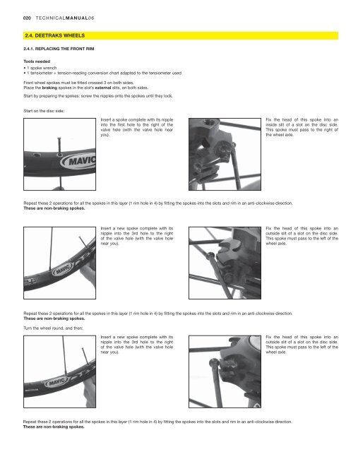
020TECHNICALMANUAL062.4. DEETRAKS WHEELS2.4.1. REPLACING THE FRONT RIMTools needed• 1 spoke wrench• 1 tensiometer + tension-reading conversion chart adapted to the tensiometer usedFront wheel spokes must be fitted crossed 3 on both sides.Place the braking spokes in the slot’s external slits, on both sides.Start by preparing the spokes: screw the nipples onto the spokes until they lock.Start on the disc side:Insert a spoke complete with its nippleinto the first hole to the right of thevalve hole (with the valve hole nearyou).Fix the head of this spoke into aninside slit of a slot on the disc side.This spoke must pass to the right ofthe wheel axle.Repeat these 2 operations for all the spokes in this layer (1 rim hole in 4) by fitting the spokes into the slots and rim in an anti-clockwise direction.These are non-braking spokes.Insert a new spoke complete with itsnipple into the 3rd hole to the rightof the valve hole (with the valve holenear you).Fix the head of this spoke into anoutside slit of a slot on the disc side.This spoke must pass to the left of thewheel axle.Repeat these 2 operations for all the spokes in this layer (1 rim hole in 4) by fitting the spokes into the slots and rim in an anti-clockwise direction.These are non-braking spokes.Turn the wheel round, and then:Insert a new spoke complete with itsnipple into the 3rd hole to the rightof the valve hole (with the valve holenear you).Fix the head of this spoke into anoutside slit of a slot on the disc side.This spoke must pass to the left of thewheel axle.Repeat these 2 operations for all the spokes in this layer (1 rim hole in 4) by fitting the spokes into the slots and rim in an anti-clockwise direction.These are non-braking spokes.
TECHNICALMANUAL06021Insert a new spoke complete with itsnipple into the 1st hole to the rightof the valve hole (with the valve holenear you).Fix the head of this spoke into anoutside slit of a slot on the non discside. This spoke must pass to the rightof the wheel axle.Repeat these 2 operations for all the spokes in this layer (1 rim hole in 4) by fitting the spokes into the slots and rim in an anti-clockwise direction.These are braking spokes.Then tighten each nipple uniformely in the rim (1 turn of the spoke wrench for each spoke and per wheel rotation) to tension the wheel.Set the final tension and center the wheel (100 to 145 kg).2.4.2. REPLACING THE REAR RIMWHEELSTools needed• 1 spoke wrench• 1 tensiometer + tension-reading conversion chart adapted to the tensiometer usedRear wheel spokes must be fitted crossed 3 on both sides:- free wheel side, the traction spokes are to be placed in the slots’ external holes;- non drive side, the traction spokes are to be placed in the slots’ internal holes;Start by preparing the spokes: screw the nipples onto the spokes until they lock.Start with the free wheel side:Insert a spoke complete with its nippleinto the first hole to the right of thevalve hole (with the valve hole nearyou).Fix the head of this spoke into aninside slit of a slot on the free wheelside. This spoke must pass to the rightof the wheel axle.Repeat these 2 operations for all the spokes in this layer (1 rim hole in 4) by fitting the spokes into the slots in an anti-clockwise direction.These are non-traction spokes.Insert a new spoke complete with itsnipple into the 3rd hole to the rightof the valve hole (with the valve holenear you).Fix the head of this spoke into anoutside slit of a slot on the free wheelside. This spoke must pass to the leftof the wheel axle.Repeat these 2 operations for all the spokes in this layer (1 rim hole in 4) by fitting the spokes into the slots and rim in an anti-clockwise direction.These are traction spokes.Turn the wheel round and repeat all the operations described above in an identical manner for the non drive side:- the spokes of the 1st layer fitted must be traction spokes (inside slits of the slots);- the spokes of the 2nd layer fitted must be braking spokes (outside slits of the slots).Then tighten each nipple uniformely in the rim (1 turn of the spoke wrench for each spoke and per wheel rotation) to tension the wheel.Set the final tension and center the wheel (115 to 155 kg).