


Create successful ePaper yourself
Turn your PDF publications into a flip-book with our unique Google optimized e-Paper software.
PARKING SENSORS<br />
Tutorial<br />
Left The HC-SR04<br />
Ultrasonic Rangefinder.<br />
Cheap-as-chips sonar<br />
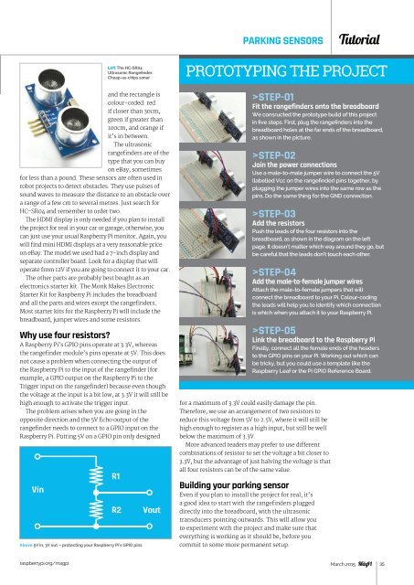
PROTOTYPING THE PROJECT<br />
and the rectangle is<br />
colour-coded: red<br />
if closer than 30cm,<br />
green if greater than<br />
100cm, and orange if<br />
it’s in between.<br />
The ultrasonic<br />
rangefinders are of the<br />
type that you can buy<br />
on eBay, sometimes<br />
for less than a pound. These sensors are often used in<br />
robot projects to detect obstacles. They use pulses of<br />
sound waves to measure the distance to an obstacle over<br />
a range of a few cm to several metres. Just search for<br />
HC‐SR04 and remember to order two.<br />
The HDMI display is only needed if you plan to install<br />
the project for real in your car or garage; otherwise, you<br />
can just use your usual Raspberry Pi monitor. Again, you<br />
will find mini HDMI displays at a very reasonable price<br />
on eBay. The model we used had a 7-inch display and<br />
separate controller board. Look for a display that will<br />
operate from 12V if you are going to connect it to your car.<br />
The other parts are probably best bought as an<br />
electronics starter kit. The Monk Makes Electronic<br />
Starter Kit for Raspberry Pi includes the breadboard<br />
and all the parts and wires except the rangefinders.<br />
Most starter kits for the Raspberry Pi will include the<br />
breadboard, jumper wires and some resistors.<br />
Why use four resistors?<br />
A Raspberry Pi’s GPIO pins operate at 3.3V, whereas<br />
the rangefinder module’s pins operate at 5V. This does<br />
not cause a problem when connecting the output of<br />
the Raspberry Pi to the input of the rangefinder (for<br />
example, a GPIO output on the Raspberry Pi to the<br />
Trigger input on the rangefinder) because even though<br />
the voltage at the input is a bit low, at 3.3V it will still be<br />
high enough to activate the trigger input.<br />
The problem arises when you are going in the<br />
opposite direction and the 5V Echo output of the<br />
rangefinder needs to connect to a GPIO input on the<br />
Raspberry Pi. Putting 5V on a GPIO pin only designed<br />
Above 5V in, 3V out – protecting your Raspberry Pi’s GPIO pins<br />
>STEP-01<br />
Fit the rangefinders onto the breadboard<br />
We consructed the prototype build of this project<br />
in five steps. First, plug the rangefinders into the<br />
breadboard holes at the far ends of the breadboard,<br />
as shown in the picture.<br />
>STEP-02<br />
Join the power connections<br />
Use a male-to-male jumper wire to connect the 5V<br />
(labelled Vcc on the rangefinder) pins together, by<br />
plugging the jumper wires into the same row as the<br />
pins. Do the same thing for the GND connection.<br />
>STEP-03<br />
Add the resistors<br />
Push the leads of the four resistors into the<br />
breadboard, as shown in the diagram on the left<br />
page. It doesn’t matter which way around they go, but<br />
be careful that the leads don’t touch each other.<br />
>STEP-04<br />
Add the male-to-female jumper wires<br />
Attach the male-to-female jumpers that will<br />
connect the breadboard to your Pi. Colour-coding<br />
the leads will help you to identify which connection<br />
is which when you attach it to your Raspberry Pi.<br />
>STEP-05<br />
Link the breadboard to the Raspberry Pi<br />
Finally, connect all the female ends of the headers<br />
to the GPIO pins on your Pi. Working out which can<br />
be tricky, but you could use a template like the<br />
Raspberry Leaf or the Pi GPIO Reference Board.<br />
for a maximum of 3.3V could easily damage the pin.<br />
Therefore, we use an arrangement of two resistors to<br />
reduce this voltage from 5V to 2.5V, where it will still be<br />
high enough to register as a high input, but still be well<br />
below the maximum of 3.3V.<br />
More advanced readers may prefer to use different<br />
combinations of resistor to set the voltage a bit closer to<br />
3.3V, but the advantage of just halving the voltage is that<br />
all four resistors can be of the same value.<br />
Building your parking sensor<br />
Even if you plan to install the project for real, it’s<br />
a good idea to start with the rangefinders plugged<br />
directly into the breadboard, with the ultrasonic<br />
transducers pointing outwards. This will allow you<br />
to experiment with the project and make sure that<br />
everything is working as it should be, before you<br />
commit to some more permanent setup.<br />
raspberrypi.org/magpi March 2015 35