Tekmar 508 Data Brochure - eComfort.com
Tekmar 508 Data Brochure - eComfort.com
Tekmar 508 Data Brochure - eComfort.com

Create successful ePaper yourself
Turn your PDF publications into a flip-book with our unique Google optimized e-Paper software.
Thermostat <strong>508</strong><br />
- <strong>Data</strong> <strong>Brochure</strong><br />
D <strong>508</strong><br />
05/10<br />
Table of Contents<br />
Display / Keypad Operation ............ pg 1<br />
Display Symbols ............................. pg 2<br />
General ........................................ pg 2-3<br />
Sequence of Operation................pg 3-4<br />
Installation ....................................pg 4-5<br />
Wiring Examples .......................... pg 6-7<br />
User Interface ................................. pg 8<br />
Menus ........................................ pg 8-10<br />
View Menu ................................ pg 8<br />
Adjust Menu ............................ pg 9<br />
Schedule Menu ...................... pg 10<br />
Error Messages ........................... pg 10<br />
Warranty ....................................... pg 12<br />
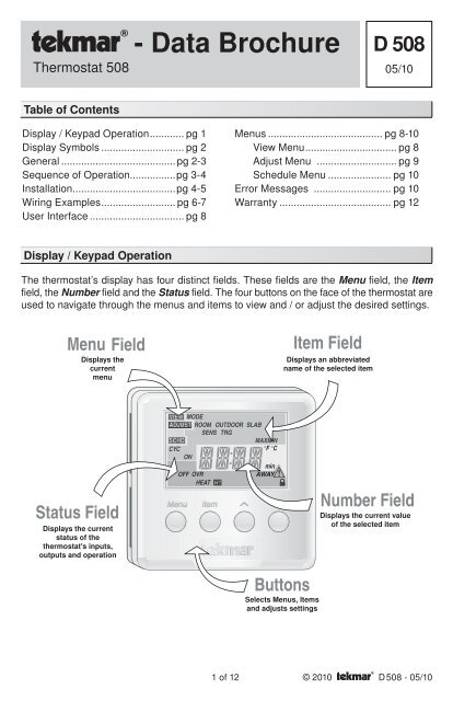
Display / Keypad Operation<br />
The thermostat’s display has four distinct fields. These fields are the Menu field, the Item<br />
field, the Number field and the Status field. The four buttons on the face of the thermostat are<br />
used to navigate through the menus and items to view and / or adjust the desired settings.<br />
Displays the<br />
current<br />
menu<br />
Displays an abbreviated<br />
name of the selected item<br />
AWAY<br />
Displays the current<br />
status of the<br />
thermostat's inputs,<br />
outputs and operation<br />
Displays the current value<br />
of the selected item<br />
Selects Menus, Items<br />
and adjusts settings<br />
1 of 12 © 2010 D <strong>508</strong> - 05/10
Display Symbols<br />
Warning<br />
Displays when an error exists.<br />
Heat One<br />
Displays when the heat contact<br />
is on.<br />
Access Level<br />
Displays when in the user<br />
access level.<br />
General<br />
CYCLES PER HOUR<br />
The thermostat operation is based on cycles per hour. The number of cycles per hour is adjustable<br />
through the HEAT CYC setting in the Adjust menu. During each cycle that heating is required,<br />
the thermostat turns on the Heat relay for a calculated amount of time. This amount of time is<br />
the “ON time”. The ON time is calculated based on the requirements of the zone. If the zone<br />
requires more heating, the ON time is increased. If the zone requires less heating, the ON time<br />
is reduced.<br />
In order to prevent short cycling of the heating relay, the<br />
Cycles Per Hour<br />
thermostat ensures that the relay remains on or off for<br />
a minimum amount of time.<br />
on off on off on off<br />
An AUTO CYC setting is available for the heating cycle.<br />
⇐ Cycle Length ⇒<br />
This setting allows the thermostat to determine the<br />
Time<br />
best number of cycles per hour that balances both<br />
temperature swings and equipment cycles.<br />
AUXILIARY SENSOR<br />
The thermostat has a single built-in sensor to measure air temperature at the<br />
thermostat. In addition to the built-in sensor, the thermostat has terminals to connect<br />
one auxiliary sensor. This sensor can be either an indoor sensor, a slab sensor, or<br />
an outdoor sensor.<br />
Indoor Sensor<br />
An indoor sensor is used to measure the air temperature in the zone that the thermostat<br />
is controlling. The temperature being read by the indoor sensor is used in the calculations<br />
of the ON time for the relay in the thermostat. This setting is made through the Adjust<br />
menu of the thermostat. If the built-in sensor is set to ON and the auxiliary sensor is set<br />
to Indoor, the temperatures of the sensors are averaged and used to calculate the ON<br />
time of the relay.<br />
Slab Sensor<br />
A slab sensor is used to measure the slab temperature in the zone that the thermostat<br />
is controlling. The temperature being read by the slab sensor is used in the calculations<br />
of the ON time for the Heat relay and allows the thermostat to operate the slab between<br />
the slab minimum and slab maximum settings.<br />
© 2010 D <strong>508</strong> - 05/10 2 of 12
Outdoor Sensor<br />
An outdoor sensor can be connected to the thermostat. The temperature measured by<br />
an outdoor sensor does not affect the ON time of the relay and is only used for display<br />
purposes.<br />
ACCESS LEVELS<br />
The <strong>508</strong> thermostat has two access levels.<br />
These access levels restrict the number of items<br />
available in the menus of the thermostat. The<br />
two access levels are User and Installer. This<br />
selection is made using the DIP switch located<br />
on the circuit board inside the thermostat.<br />
Installer access level - allows the installer<br />
to adjust all of the settings in the thermostat<br />
including those required to match the thermostat<br />
to the mechanical system and the devices<br />
used.<br />
User access level - allows the end user<br />
to adjust the temperatures used by the<br />
thermostat.<br />
Sequence of Operation<br />
For 3 wires,<br />
install jumper<br />
R to Rh<br />
NO<br />
POWER<br />
1 2<br />
Sensor<br />
<strong>508</strong><br />
944-02<br />
Thermostat <strong>508</strong><br />
One Stage Heat<br />
Power: 24 V ±10% 50/60 Hz 1.5 VA.<br />
Relay: 24 V (ac) 2 A Class 2<br />
Made in<br />
Canada<br />
Meets Class B:<br />
Canadian ICES Apr 2010<br />
FCC Part 15 Lot 1234<br />
Access level<br />
Installer User<br />
Not used<br />
AIR SENSOR(S) ONLY OPERATION<br />
When operating with only an air sensor, the ON time for the Heat relay is calculated to<br />
satisfy the requirements of the air sensor.<br />
SLAB SENSOR ONLY OPERATION<br />
When operating with only a slab sensor, the ON time for the Heat relay is calculated to<br />
satisfy the requirements of the slab sensor. The thermostat operates to maintain the slab<br />
at the minimum slab temperature setting.<br />
NOTE: Operating with only a slab sensor can lead to either overheating or underheating<br />
of the space.<br />
AIR AND SLAB SENSOR OPERATION<br />
When operating with both air and slab sensors, the thermostat calculates an ON time for the<br />
Heat relay to satisfy the slab sensor’s requirements and an ON time to satisfy the air sensor’s<br />
requirements. The Heat relay operates for the longer of these two ON times.<br />
During light heating loads, overheating can occur due to the minimum slab temperature<br />
requirements.<br />
During heavy heating loads, the maximum slab temperature setting limits the ON time of<br />
the Heat relay. In this situation, underheating can occur.<br />
24 V<br />
3 4 5 6<br />
C R Rh W<br />
Dip Switch<br />
Set to User access level once installation and settings have been <strong>com</strong>pleted.<br />
Note: DIP switch 2 is not used.<br />
1 2<br />
ON<br />
3 of 12 © 2010 D <strong>508</strong> - 05/10
MODE<br />
Heat In the heat mode, the Heat relay is operated to satisfy the temperature<br />
requirement of the zone.<br />
Off In the OFF mode, the Heat relay is not operated.<br />
NOTE: If an air or slab sensor is active in the OFF mode, a freeze protection is enabled<br />
that allows the Heat relay to be operated to keep the zone above 35°F (2°C).<br />
Installation<br />
STEP ONE<br />
GETTING READY<br />
Check the contents of this package. If any of the contents are missing or damaged, please<br />
contact your wholesaler or tekmar sales representative for assistance.<br />
Type <strong>508</strong> Includes: • One Thermostat <strong>508</strong> • <strong>Data</strong> <strong>Brochure</strong> D <strong>508</strong> • User <strong>Brochure</strong> U <strong>508</strong><br />
STEP TWO REMOVING THE FRONT COVER<br />
Place a screwdriver or similar object into the small slot located in the top of the thermostat.<br />
Push the screwdriver against the plastic tab and pull the top of the front cover so that it pivots<br />
around the bottom edge of the base.<br />
1 Push tab<br />
2<br />
Remove cover<br />
Menu Item<br />
STEP THREE<br />
MOUNTING THE BASE<br />
The thermostat should be installed on an interior wall of the desired zone approximately 5’ (1.5<br />
m) above the floor. Do not mount the thermostat in a location that may be affected by localized<br />
heat sources or cold drafts. It may be necessary to install a draft barrier behind the thermostat to<br />
prevent air from blowing through the wiring hole and affecting the thermostat’s built-in sensor.<br />
Mount the base directly to the wall using two #6<br />
1” screws. The screws are inserted through the<br />
mounting holes and must be securely fastened<br />
to the wall. If possible, at least one of the screws<br />
should enter a wall stud or similar surface.<br />
If the thermostat is to be mounted to a 2” x<br />
4” electrical box, order an Adaptor Plate 007.<br />
This plate mounts to the electrical box and the<br />
thermostat mounts to the plate. Ensure that the<br />
electrical box does not provide cold air to the<br />
thermostat.<br />
#6 1” screws<br />
© 2010 D <strong>508</strong> - 05/10 4 of 12
NOTE: If the <strong>508</strong> is to be used for remote sensing (i.e. The built-in air sensor is disabled<br />
and an indoor sensor is being used.) Mount the thermostat in the desired location in an<br />
appropriate manner.<br />
STEP FOUR<br />
ROUGH IN WIRING<br />
• 18 AWG or similar wire is re<strong>com</strong>mended for all 24 V (ac) wiring.<br />
• All wires are to be stripped to 1/4” (6 mm) to ensure proper connection to the control.<br />
• Run wires from the 24 V (ac) power to the thermostat. Use a clean power source to<br />
• If an auxiliary sensor is used, install the sensor according to the appropriate <strong>Data</strong><br />
<strong>Brochure</strong> and run two wires from the sensor to the thermostat.<br />
• Run wires from the heating device to the thermostat.<br />
STEP FIVE WIRING THE THERMOSTAT<br />
(Refer to the examples on the following page.)<br />
24 V (ac) Power<br />
Connect the 24 V (ac) power to the R and C terminals of the thermostat. This connection<br />
provides power to the microprocessor and display of the thermostat.<br />
Auxiliary Sensor<br />
Either an indoor, slab, or outdoor sensor may be connected to the auxiliary sensor input.<br />
Connect the two wires from the auxiliary sensor to the Sensor terminals.<br />
Heat Relay (Rh – W)<br />
The Heat Relay Rh – W terminals are an isolated output. There is no power available<br />
on these terminals from the thermostat. These terminals are to be used as a switch for<br />
a 24 V (ac) circuit. This circuit can operate a low current 24 V (ac) device directly or an<br />
external relay to enable a line voltage or high current device.<br />
STEP SIX<br />
INSTALLING THE FRONT COVER<br />
Align the hinges on the bottom of the front cover with the bottom of the thermostat mounting<br />
base. Pivot the front cover around the bottom hinges and push the top against the mounting<br />
base until it snaps firmly in place.<br />
2 Pivot front<br />
cover around<br />
bottom hinges<br />
Menu Item<br />
1 Align hinges<br />
on bottom<br />
of front cover<br />
5 of 12 © 2010 D <strong>508</strong> - 05/10
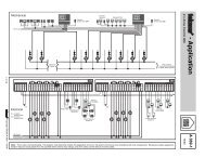
Wiring Examples<br />
115 V (ac)<br />
24 V (ac)<br />
Sensor Wires<br />
Wiring to a tekmar Wiring Center 315 or 316<br />
Zone 1 Expansion End Switch<br />
W R C tN4 C tN4 X X<br />
Input Power<br />
R C<br />
tN4 C R W tN4 C R W tN4 C R<br />
Zone 2<br />
Zone 3<br />
Zone 4<br />
Zone 1<br />
Zone 2<br />
Zone 3<br />
Zone 4<br />
Power<br />
End Switch<br />
Input Power:<br />
End Switch:<br />
Pump Relays:<br />
Zone Power:<br />
tN4 Wiring Center 316<br />
Four Zone Pumps<br />
W<br />
24 V (ac) ±10% 60 Hz<br />
11 VA Class 2<br />
24 V (ac) 2 A<br />
115 V (ac) 5 A<br />
115 V (ac) 12 A<br />
Made in Canada<br />
tektra 1031-01<br />
H8002A<br />
C R Rh W<br />
24 V<br />
3 4 5 6<br />
For 3 wires,<br />
install jumper<br />
R to Rh<br />
NO<br />
POWER<br />
1 2<br />
Sensor<br />
<strong>508</strong><br />
944-02<br />
Thermostat <strong>508</strong><br />
One Stage Heat<br />
Power: 24 V ±10% 50/60 Hz 1.5 VA.<br />
Relay: 24 V (ac) 2 A Class 2<br />
Made in<br />
Canada<br />
Meets Class B:<br />
Canadian ICES Apr 2010<br />
FCC Part 15 Lot 1234<br />
Access level<br />
Installer User<br />
Not used<br />
1 2<br />
ON<br />
Red<br />
Use at least 167°F (75°C) conductors<br />
Black<br />
Auxiliary Sensor<br />
24 V (ac)<br />
Class 2<br />
Transformer<br />
N<br />
L 115 V (ac)<br />
115 V (ac)<br />
24 V (ac)<br />
Sensor Wires<br />
Wiring to 24 V (ac) Zone Valve<br />
M<br />
Zone<br />
Valve<br />
24 V<br />
3 4 5 6<br />
C R Rh W<br />
For 3 wires,<br />
install jumper<br />
R to Rh<br />
NO<br />
POWER<br />
1 2<br />
Sensor<br />
Thermostat <strong>508</strong><br />
One Stage Heat<br />
<strong>508</strong><br />
944-02<br />
Power: 24 V ±10% 50/60 Hz 1.5 VA.<br />
Relay: 24 V (ac) 2 A Class 2<br />
Made in<br />
Canada<br />
Meets Class B:<br />
Canadian ICES Apr 2010<br />
FCC Part 15 Lot 1234<br />
Access level<br />
Installer User<br />
Not used<br />
1 2<br />
ON<br />
N<br />
115 V (ac)<br />
L<br />
24 V (ac)<br />
Class 2<br />
Transformer<br />
Auxiliary Sensor<br />
© 2010 D <strong>508</strong> - 05/10 6 of 12
115 V (ac)<br />
24 V (ac)<br />
Sensor Wires<br />
Wiring to Unpowered 24 V (ac) Relay<br />
Unpowered<br />
Relay<br />
3<br />
4<br />
5<br />
6<br />
2<br />
1<br />
8<br />
7<br />
Zone Pump<br />
24 V<br />
3 4 5 6<br />
C R Rh W<br />
For 3 wires,<br />
install jumper<br />
R to Rh<br />
NO<br />
POWER<br />
1 2<br />
Sensor<br />
<strong>508</strong><br />
944-02<br />
Thermostat <strong>508</strong><br />
One Stage Heat<br />
Power: 24 V ±10% 50/60 Hz 1.5 VA.<br />
Relay: 24 V (ac) 2 A Class 2<br />
Made in<br />
Canada<br />
Meets Class B:<br />
Canadian ICES Apr 2010<br />
FCC Part 15 Lot 1234<br />
Access level<br />
Installer User<br />
Not used<br />
1 2<br />
ON<br />
115 V (ac)<br />
N<br />
L<br />
Class 2<br />
Transformer<br />
24 V (ac)<br />
Auxiliary Sensor<br />
115 V (ac)<br />
24 V (ac)<br />
Sensor Wires<br />
Wiring to Switching Relay<br />
24 V<br />
Com<br />
W R W R<br />
(T) (T) (T) (T)<br />
Switching Relay<br />
W R<br />
(T) (T)<br />
24 V<br />
3 4 5 6<br />
C R Rh W<br />
For 3 wires,<br />
install jumper<br />
R to Rh<br />
NO<br />
POWER<br />
1 2<br />
Sensor<br />
<strong>508</strong><br />
944-02<br />
Thermostat <strong>508</strong><br />
One Stage Heat<br />
Power: 24 V ±10% 50/60 Hz 1.5 VA.<br />
Relay: 24 V (ac) 2 A Class 2<br />
Made in<br />
Canada<br />
Meets Class B:<br />
Canadian ICES Apr 2010<br />
FCC Part 15 Lot 1234<br />
Access level<br />
Installer User<br />
Not used<br />
1 2<br />
ON<br />
Class 2<br />
Transformer<br />
Zone 1 Zone 2 Zone 3<br />
X X H N H N H N N H<br />
Zone Pump<br />
N<br />
115 V (ac)<br />
L<br />
Auxiliary Sensor<br />
7 of 12 © 2010 D <strong>508</strong> - 05/10
User Interface<br />
MENU BUTTON<br />
The menus display in the Menu Field at the left of the LCD.<br />
Three menus are available:<br />
• View<br />
• Adjust<br />
• Schd (Schedule)<br />
To select a menu, press and release the Menu button.<br />
ITEM BUTTON<br />
In each menu, a group of items can be selected. The abbreviated name of the selected<br />
item displays in the Item field of the LCD display.<br />
• To view the next available item, press and release the Item button.<br />
• To view the previous item, hold down the Item button and press and release the Up<br />
button.<br />
ADJUSTING A SETTING<br />
To adjust a setting:<br />
1. Use the Menu button to select the appropriate menu.<br />
2. Use the Item button to find the desired setting.<br />
3. Use the Up or Down button to adjust the setting.<br />
View Menu<br />
ROOM TARGET<br />
The current desired air temperature for the space. This item is<br />
only available in the Installer access level.(Must have an active<br />
air sensor.)<br />
ROOM<br />
The current air temperature for the space. (Must have at least one<br />
active air sensor. This is the average of all active air sensors.<br />
OUTDOOR<br />
The current temperature at the outdoor sensor.<br />
(SENS must be set to OUT.)<br />
SLAB<br />
The current slab temperature. (Must have an active slab sensor.)<br />
The MIN segment is displayed when running at Slab Minimum.<br />
© 2010 D <strong>508</strong> - 05/10 8 of 12
Adjust Menu<br />
MODE<br />
Current mode of operation of the thermostat.<br />
OFF, HEAT<br />
ROOM HEAT<br />
Desired temperature for heating. (Must have an active air sensor<br />
and be set to HEAT.)<br />
35 to 100°F (1.5 to 38.0°C)<br />
SLAB MINIMUM<br />
Minimum slab temperature. (Must have an active slab sensor.)<br />
OFF, 34 to 122°F (OFF, 1.0 to 50.0°C)<br />
SLAB MAXIMUM<br />
Maximum slab temperature. This item is only available in the<br />
Installer access level. (Must have an active slab sensor.)<br />
34 to 122°F, OFF (1.0 to 50.0°C, OFF)<br />
SENSOR<br />
Selects the type of auxiliary sensor present. This item is only<br />
available in the Installer access level.<br />
OFF, Indr, SLAB, OUT<br />
ROOM SENSOR<br />
Selects whether the built-in sensor is functional or not. This item<br />
is only available in the Installer access level.<br />
OFF, On<br />
HEATING CYCLE<br />
Determines the number of cycles per hour for the heating equipment.<br />
This item is only available in the Installer access level.<br />
Au, 2 to 12<br />
UNITS<br />
The units of temperature used to display the items.<br />
°F, °C<br />
9 of 12 © 2010 D <strong>508</strong> - 05/10
Schedule Menu<br />
AWAY OVERRIDE<br />
Selects an automatic setback temperature of 62°F (16.5°C) without<br />
altering the normal room temperature setting (Slab minimum is<br />
ignored). Select between None & Away.<br />
Error Messages<br />
E01<br />
The thermostat was unable to read a piece of information stored<br />
in its memory. The thermostat was required to load the factory<br />
settings. The thermostat will stop operation until all settings are<br />
checked. To clear this error, select the Installer access level and<br />
check all of the settings in the Adjust menu.<br />
E02<br />
There are no active sensors selected on the thermostat. Either the<br />
internal sensor must be turned on or the auxiliary sensor must be<br />
set to either INDR or SLAB. After the fault is corrected, press any<br />
button to clear the error message.<br />
ROOM SHORT<br />
The thermostat’s internal air sensor is short circuit. This cannot<br />
be repaired in the field. The thermostat should be replaced or<br />
returned for repair.<br />
ROOM OPEN<br />
The thermostat’s internal air sensor is open circuit. This cannot be<br />
repaired in the field. Either turn off the internal sensor and use an<br />
auxiliary sensor set to INDR or replace the thermostat. After the<br />
fault is corrected, press any button to clear the error message.<br />
SENSOR SHORT<br />
The auxiliary sensor is short circuit. Locate and repair the problem<br />
as described in the appropriate sensor brochure. After the fault is<br />
corrected, press any button to clear the error message.<br />
SENSOR OPEN<br />
The auxiliary sensor is open circuit. Locate and repair the problem<br />
as described in the appropriate sensor brochure. After the fault is<br />
corrected, press any button to clear the error message.<br />
© 2010 D <strong>508</strong> - 05/10 10 of 12
Notes<br />
11 of 12 © 2010 D <strong>508</strong> - 05/10
Technical <strong>Data</strong><br />
THERMOSTAT <strong>508</strong> One Stage Heat<br />
Literature D <strong>508</strong>, U <strong>508</strong><br />
Control<br />
Microprocessor PI control; This is not a safety (limit) control.<br />
Packaged weight<br />
0.46 lb. (210 g), Enclosure J, white PVC plastic<br />
Dimensions<br />
2-7/8” H x 2-7/8” W x 13/16” D (73 x 73 x 21 mm)<br />
Approvals CSA C US, CSA 22.2 N o 24 and UL 873, meets class B: ICES & FCC Part 15.<br />
Ambient conditions Indoor use only, -22 to 131°F (-30 to 55°C), < 90% RH non-condensing.<br />
Power Supply<br />
24 V (ac) ±10%, 50/60 Hz, 1.5 VA<br />
Relay 24 V (ac) 2 A, Class 2<br />
Sensors NTC thermistor, 10 kΩ @ 77°F (25°C ±0.2°C) ß=3892<br />
Included<br />
None<br />
Optional tekmar type #070, 071, 072, 073, 076, 077, 078, 079, 082, 084.<br />
Limited Warranty and Product Return Procedure<br />
Limited Warranty The liability of tekmar under this warranty is limited. The Purchaser, by taking receipt of<br />
any tekmar product (“Product”), acknowledges the terms of the Limited Warranty in effect at the time of<br />
such Product sale and acknowledges that it has read and understands same.<br />
The tekmar Limited Warranty to the Purchaser on the Products sold hereunder is a manufacturer’s passthrough<br />
warranty which the Purchaser is authorized to pass through to its customers. Under the Limited<br />
Warranty, each tekmar Product is warranted against defects in workmanship and materials if the Product<br />
is installed and used in <strong>com</strong>pliance with tekmar’s instructions, ordinary wear and tear excepted. The passthrough<br />
warranty period is for a period of twenty-four (24) months from the production date if the Product is<br />
not installed during that period, or twelve (12) months from the documented date of installation if installed<br />
within twenty-four (24) months from the production date.<br />
The liability of tekmar under the Limited Warranty shall be limited to, at tekmar’s sole discretion: the cost of parts<br />
and labor provided by tekmar to repair defects in materials and / or workmanship of the defective product; or to<br />
the exchange of the defective product for a warranty replacement product; or to the granting of credit limited to the<br />
original cost of the defective product, and such repair, exchange or credit shall be the sole remedy available from<br />
tekmar, and, without limiting the foregoing in any way, tekmar is not responsible, in contract, tort or strict product<br />
liability, for any other losses, costs, expenses, inconveniences, or damages, whether direct, indirect, special, secondary,<br />
incidental or consequential, arising from ownership or use of the product, or from defects in workmanship<br />
or materials, including any liability for fundamental breach of contract.<br />
The pass-through Limited Warranty applies only to those defective Products returned to tekmar during the warranty<br />
period. This Limited Warranty does not cover the cost of the parts or labor to remove or transport the defective<br />
Product, or to reinstall the repaired or replacement Product, all such costs and expenses being subject to<br />
Purchaser’s agreement and warranty with its customers.<br />
Any representations or warranties about the Products made by Purchaser to its customers which are different from<br />
or in excess of the tekmar Limited Warranty are the Purchaser’s sole responsibility and obligation. Purchaser shall<br />
indemnify and hold tekmar harmless from and against any and all claims, liabilities and damages of any kind or<br />
nature which arise out of or are related to any such representations or warranties by Purchaser to its customers.<br />
The pass-through Limited Warranty does not apply if the returned Product has been damaged by negligence by<br />
persons other than tekmar, accident, fire, Act of God, abuse or misuse; or has been damaged by modifications,<br />
alterations or attachments made subsequent to purchase which have not been authorized by tekmar; or if the Product<br />
was not installed in <strong>com</strong>pliance with tekmar’s instructions and / or the local codes and ordinances; or if due to<br />
defective installation of the Product; or if the Product was not used in <strong>com</strong>pliance with tekmar’s instructions.<br />
THIS WARRANTY IS IN LIEU OF ALL OTHER WARRANTIES, EXPRESS OR IMPLIED, WHICH THE GOVERNING<br />
LAW ALLOWS PARTIES TO CONTRACTUALLY EXCLUDE, INCLUDING, WITHOUT LIMITATION, IMPLIED WAR-<br />
RANTIES OF MERCHANTABILITY AND FITNESS FOR A PARTICULAR PURPOSE, DURABILITY OR DESCRIP-<br />
TION OF THE PRODUCT, ITS NON-INFRINGEMENT OF ANY RELEVANT PATENTS OR TRADEMARKS, AND<br />
ITS COMPLIANCE WITH OR NON-VIOLATION OF ANY APPLICABLE ENVIRONMENTAL, HEALTH OR SAFETY<br />
LEGISLATION; THE TERM OF ANY OTHER WARRANTY NOT HEREBY CONTRACTUALLY EXCLUDED IS LIM-<br />
ITED SUCH THAT IT SHALL NOT EXTEND BEYOND TWENTY-FOUR (24) MONTHS FROM THE PRODUCTION<br />
DATE, TO THE EXTENT THAT SUCH LIMITATION IS ALLOWED BY THE GOVERNING LAW.<br />
Product Warranty Return Procedure All Products that are believed to have defects in workmanship or materials<br />
must be returned, together with a written description of the defect, to the tekmar Representative assigned to<br />
the territory in which such Product is located. If tekmar receives an inquiry from someone other than a tekmar<br />
Representative, including an inquiry from Purchaser (if not a tekmar Representative) or Purchaser’s customers,<br />
regarding a potential warranty claim, tekmar’s sole obligation shall be to provide the address and other contact<br />
information regarding the appropriate Representative.<br />
All specifications are subject<br />
to change without notice<br />
tekmar Control Systems Ltd., Canada<br />
tekmar Control Systems, Inc., U.S.A.<br />
Head Office: 5100 Silver Star Road<br />
Vernon, B.C. Canada V1B 3K4<br />
(250) 545-7749 Fax. (250) 545-0650<br />
Web Site: www.tekmarcontrols.<strong>com</strong><br />
Product design, software and literature<br />
are Copyright © 2010 by:<br />
tekmar Control Systems Ltd. and tekmar<br />
Control Systems, Inc.<br />
12 of 12 D <strong>508</strong> - 05/10.