Horizontal Panel Saw - Southern Tool
Horizontal Panel Saw - Southern Tool
Horizontal Panel Saw - Southern Tool

You also want an ePaper? Increase the reach of your titles
YUMPU automatically turns print PDFs into web optimized ePapers that Google loves.
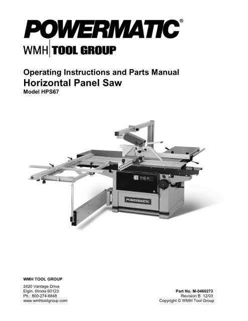
Operating Instructions and Parts Manual<br />
<strong>Horizontal</strong> <strong>Panel</strong> <strong>Saw</strong><br />
Model HPS67<br />
WMH TOOL GROUP<br />
2420 Vantage Drive<br />
Elgin, Illinois 60123 Part No. M-0460273<br />
Ph.: 800-274-6848 Revision B 12/03<br />
www.wmhtoolgroup.com<br />
Copyright © WMH <strong>Tool</strong> Group
This manual has been prepared for the owner and operators of a Powermatic Model HPS67<br />
<strong>Horizontal</strong> <strong>Panel</strong> <strong>Saw</strong>. Its purpose, aside from machine operation, is to promote safety through the<br />
use of accepted correct operating and maintenance procedures. Completely read the safety and<br />
maintenance instructions before operating or servicing the machine. To obtain maximum life and<br />
efficiency from your panel saw, and to aid in using the machine safely, read this manual thoroughly<br />
and follow all instructions carefully.<br />
Warranty & Service<br />
WMH <strong>Tool</strong> Group warrants every product it sells. If one of our tools needs service or repair, one of our Authorized<br />
Repair Stations located throughout the United States can give you quick service.<br />
In most cases, any one of these WMH <strong>Tool</strong> Group Repair Stations can authorize warranty repair, assist you in<br />
obtaining parts, or perform routine maintenance and major repair on your JET, Performax, Powermatic or Wilton<br />
tools.<br />
For the name of an Authorized Repair Station in your area, call 1-800-274-6848.<br />
More Information<br />
WMH <strong>Tool</strong> Group is consistently adding new products to the line. For complete, up-to-date product information,<br />
check with your local WMH <strong>Tool</strong> Group distributor or visit wmhtoolgroup.com.<br />
Limited Warranty<br />
WMH <strong>Tool</strong> Group (including JET, Performax, Powermatic and Wilton brands) makes every effort to assure that its<br />
products meet high quality and durability standards and warrants to the original retail consumer/purchaser of our<br />
products that each product be free from defects in materials and workmanship as follows: 1 YEAR LIMITED<br />
WARRANTY ON ALL PRODUCTS UNLESS SPECIFIED OTHERWISE. This warranty does not apply to defects<br />
due directly or indirectly to misuse, abuse, negligence or accidents, normal wear-and-tear, repair or alterations<br />
outside our facilities, or to a lack of maintenance.<br />
WMH TOOL GROUP LIMITS ALL IMPLIED WARRANTIES TO THE PERIOD SPECIFIED ABOVE, FROM THE<br />
DATE THE PRODUCT WAS PURCHASED AT RETAIL. EXCEPT AS STATED HEREIN, ANY IMPLIED<br />
WARRANTIES OR MERCHANTIBILITY AND FITNESS ARE EXCLUDED. SOME STATES DO NOT ALLOW<br />
LIMITATIONS ON HOW LONG THE IMPLIED WARRANTY LASTS, SO THE ABOVE LIMITATION MAY NOT<br />
APPLY TO YOU. WMH TOOL GROUP SHALL IN NO EVENT BE LIABLE FOR DEATH, INJURIES TO PERSONS<br />
OR PROPERTY, OR FOR INCIDENTAL, CONTINGENT, SPECIAL, OR CONSEQUENTIAL DAMAGES ARISING<br />
FROM THE USE OF OUR PRODUCTS. SOME STATES DO NOT ALLOW THE EXCLUSION OR LIMITATION OF<br />
INCIDENTAL OR CONSEQUENTIAL DAMAGES, SO THE ABOVE LIMITATION OR EXCLUSION MAY NOT APPLY<br />
TO YOU.<br />
To take advantage of this warranty, the product or part must be returned for examination, postage prepaid, to an<br />
Authorized Repair Station designated by our office. Proof of purchase date and an explanation of the complaint<br />
must accompany the merchandise. If our inspection discloses a defect, WMH <strong>Tool</strong> Group will either repair or<br />
replace the product, or refund the purchase price if we cannot readily and quickly provide a repair or replacement, if<br />
you are willing to accept a refund. WMH <strong>Tool</strong> Group will return repaired product or replacement at our expense, but<br />
if it is determined there is no defect, or that the defect resulted from causes not within the scope of our warranty,<br />
then the user must bear the cost of storing and returning the product. This warranty gives you specific legal rights;<br />
you may also have other rights, which vary from state to state.<br />
WMH <strong>Tool</strong> Group sells through distributors only. WMH <strong>Tool</strong> Group reserves the right to effect at any time, without<br />
prior notice, those alterations to parts, fittings, and accessory equipment which they may deem necessary for any<br />
reason whatsoever.
TABLE OF CONTENTS<br />
Safety Rules........................................................................................................................................................ 4-5<br />
Specifications ..........................................................................................................................................................6<br />
Machine Dimensions ...............................................................................................................................................7<br />
Unpacking ...............................................................................................................................................................8<br />
Installation & Assembly............................................................................................................................................8<br />
Installing Extension Tables..................................................................................................................................9<br />
Installing Crosscut Table.....................................................................................................................................9<br />
Installing Crosscut Fence ....................................................................................................................................9<br />
Installing Guide Bar...........................................................................................................................................10<br />
Installing Rip Fence ..........................................................................................................................................10<br />
Installing Overarm ............................................................................................................................................10<br />
Installing Blade Guard.......................................................................................................................................11<br />
Installing Mitre Fence........................................................................................................................................11<br />
Electrical Connections.......................................................................................................................................11<br />
Installing/Replacing Main Blade ........................................................................................................................12<br />
Installing/Replacing Scoring Blade ....................................................................................................................12<br />
Riving Knife ......................................................................................................................................................13<br />
Starting the Machine .........................................................................................................................................13<br />
Dust Collection..................................................................................................................................................14<br />
Adjustments...........................................................................................................................................................14<br />
Sliding Table Parallel to Blade ..........................................................................................................................14<br />
Setting Main Blade............................................................................................................................................14<br />
Setting Scoring Blade .......................................................................................................................................15<br />
Setting Blade Guard..........................................................................................................................................15<br />
Sliding Table Lock ............................................................................................................................................15<br />
Crosscut Fence.................................................................................................................................................16<br />
Mitre Fence.......................................................................................................................................................17<br />
Rip Fence .........................................................................................................................................................17<br />
Rip Fence Scale Calibration..............................................................................................................................18<br />
Tensioning the Belt ...........................................................................................................................................18<br />
Precision Tuning Your <strong>Panel</strong> <strong>Saw</strong>..........................................................................................................................18<br />
Free Cut (Blade to Sliding Table) ......................................................................................................................19<br />
Troubleshooting Free Cut (Blade to Sliding Table) ............................................................................................21<br />
Free Cut (Blade to Rip Fence) ..........................................................................................................................21<br />
Troubleshooting Free Cut (Blade to Rip Fence).................................................................................................22<br />
Square Cut........................................................................................................................................................23<br />
Scoring Blade ...................................................................................................................................................23<br />
Operation ..............................................................................................................................................................24<br />
Maintenance..........................................................................................................................................................24<br />
Optional Accessories .............................................................................................................................................25<br />
Trouble-shooting....................................................................................................................................................26<br />
Parts Lists & Exploded Views:<br />
Motor & Arbor Assembly ..............................................................................................................................27-29<br />
Scoring Motor & Arbor Assembly .................................................................................................................30-31<br />
Stand & Table Assembly.............................................................................................................................32-33<br />
Sliding Table Assembly................................................................................................................................34-36<br />
Support Arm Assembly ................................................................................................................................37-38<br />
Crosscut Fence Assembly............................................................................................................................39-40<br />
Rip Fence Assembly ....................................................................................................................................41-42<br />
Overarm Guard Assembly............................................................................................................................43-44<br />
Electrical Components...........................................................................................................................................45<br />
Electrical Schematic ..............................................................................................................................................46<br />
3
! SAFETY RULES<br />
As with all machines, there is a certain amount of hazard involved with the use of this panel saw. Use the machine<br />
with the respect and caution demanded where safety precautions are concerned. When normal safety precautions<br />
are overlooked or ignored, personal injury to the operator can result.<br />
Read, understand and follow the safety and operating instructions found in this manual. Know the limitations and<br />
hazards associated with this machine.<br />
Electrical grounding. Make certain that the machine frame is electrically grounded and that a ground lead is<br />
included in the incoming electrical service. In cases where a cord and plug are used, make certain that the<br />
grounding plug connects to a suitable ground. Follow the grounding procedure indicated in the National Electrical<br />
Code.<br />
Eye safety. Wear an approved safety shield, goggles, or glasses to protect eyes. (NOTE: Common eyeglasses<br />
are only impact-resistant, they are not safety glasses.)<br />
Personal protection. Before operating the machine, remove tie, rings, watch and other jewelry and roll up sleeves<br />
above the elbows. Remove all loose outer clothing and confine long hair. Protective type footwear should be used.<br />
Where the noise exceeds the level of exposure allowed in Section 1910.95 of the OSHA Regulations, use hearing<br />
protective devices. Do not wear gloves.<br />
Guards. Keep the machine guards in place for every operation for which they can be used. If any guards are<br />
removed for maintenance, DO NOT OPERATE the machine until the guards are reinstalled.<br />
Work area. Keep the floor around the machine clean and free of scrap material, saw dust, oil and other liquids to<br />
minimize the danger of tripping or slipping. Be sure the table is free of all scrap, foreign material and tools before<br />
starting to cut. Make certain the work area is well lighted and that a proper exhaust system is used to minimize dust.<br />
Powermatic recommends the use of anti-skid floor strips on the floor area where the operator normally stands and<br />
that each machine’s work area be marked off. Provide adequate work space around the machine.<br />
Avoid accidental starting: Make certain motor switch is in off position before connecting power to the planer.<br />
Operator position. Maintain a balanced stance and keep your body under control at all times. Do not overreach.<br />
Do not stand in line with the saw blade or work piece and do not allow anyone else to do so. Never climb on or near<br />
the saw.<br />
Housekeeping. Before turning on machine, remove all extra equipment such as keys, wrenches, scrap, and<br />
cleaning rags away from the saw.<br />
Careless acts. Give the work you are doing your undivided attention. Looking around, carrying on a conversation,<br />
and “horseplay” are careless acts that can result in serious injury.<br />
Disconnect machine before performing any service or maintenance or when changing blades. A machine under<br />
repair should be RED TAGGED to show it should not be used until the maintenance is complete.<br />
Maintain tools in top condition. Check the saw blade for cracks or missing teeth. Do not use a cracked or dull<br />
blade or one with missing teeth or improper set. Make sure the blade is securely locked on the arbor.<br />
Hand safety. Keep hands clear of the blade area. Do not reach past the blade to clear parts or scrap with the saw<br />
blade running. Never saw free hand. Avoid awkward operations and hand positions where a sudden slip could<br />
cause your hand to contact the blade.<br />
<strong>Saw</strong> blade rotation: Be sure the main saw blade rotates clockwise when viewed from the front (operator’s side).<br />
The scoring blade should rotate counterclockwise when viewed from front.<br />
4
Material condition: Do not attempt to saw boards with loose knots or with nails or other foreign material, on its<br />
surface. Do not attempt to saw twisted, warped, bowed or “in wind” stock unless one edge has been jointed for<br />
guiding purposes prior to sawing.<br />
Machine adjustments: Make all machine adjustments with power off.<br />
Job completion. If the operator leaves the machine area for any reason, he should turn “off” the power to the saw<br />
motor and wait until the saw blade comes to a complete stop before his departure. In addition, if the operation is<br />
complete, he should clean the saw and the work area. NEVER clean the saw with power "on" and never use the<br />
hands to clear sawdust and debris; use a brush.<br />
Replacement parts. Use only Powermatic or factory authorized replacement parts and accessories; otherwise the<br />
warranty and guarantee is null and void.<br />
Misuse. Do not use this Powermatic panel saw for other than its intended use. If used for other purposes,<br />
Powermatic disclaims any real or implied warranty and holds itself harmless for any injury or damage which may<br />
result from that use.<br />
If you are not thoroughly familiar with the operation of panel saws, obtain advice from your supervisor, instructor or<br />
other qualified person.<br />
Drugs, alcohol, medication. Do not operate this machine while under the influence of drugs, alcohol, or any<br />
medication.<br />
Health hazards. Some dust created by power sanding, sawing, grinding, drilling and other construction activities<br />
contains chemicals known to cause cancer, birth defects or other reproductive harm. Some examples of these<br />
chemicals are:<br />
* Lead from lead-based paint.<br />
* Crystalline silica from bricks and cement and other masonry products.<br />
* Arsenic and chromium from chemically-treated lumber.<br />
Your risk from these exposures varies, depending on how often you do this type of work. To reduce your exposure<br />
to these chemicals, work in a well-ventilated area, and work with approved safety equipment, such as those dust<br />
masks that are specifically designed to filter out microscopic particles.<br />
Familiarize yourself with the following safety notices used in this manual:<br />
!<br />
CAUTION: (This means that if precautions are not heeded, it may result in minor or moderate injury<br />
and/or possible machine damage)<br />
!<br />
WARNING: (This means that if precautions are not heeded, it could result in serious injury or<br />
possibly even death).<br />
5
SPECIFICATIONS: Model HPS67 <strong>Horizontal</strong> <strong>Panel</strong> <strong>Saw</strong><br />
Stock number................................................................................................................................................... 1791287<br />
Main motor...........................................................................................................................................5 HP, 3Ph, 230V<br />
Blade speed .................................................................................................................................................. 4500 RPM<br />
Blade size .................................................................................................................................................12” (315 mm)<br />
Arbor size............................................................................................................................................................30 mm<br />
Dado size (width x bore).............................................................................................................................13/16” x 5/8”<br />
Cutting depth.............................................................................................................................................. 4” (100 mm)<br />
Scoring motor .....................................................................................................................................................3/4 HP<br />
Scoring blade size.................................................................................................................................. 100 to 120 mm<br />
Scoring blade arbor.............................................................................................................................................20 mm<br />
Scoring blade speed...................................................................................................................................... 6500 RPM<br />
Sliding table carriage width .......................................................................................................................13” (330 mm)<br />
Sliding table carriage stroke ....................................................................................................................67” (1700 mm)<br />
Rip capacity ............................................................................................................................................50” (1270 mm)<br />
Main and scoring blade tilt....................................................................................................................90 to 45 degrees<br />
Main table size cast iron......................................................................................................... 37” x 20” (940 x 508 mm)<br />
Right side extension table ...................................................................................................... 31” x 18” (790 x 460 mm)<br />
Rear extension table size ....................................................................................................... 30” x 20” (760 x 500 mm)<br />
Working table height .................................................................................................................................34” (860 mm)<br />
Crosscut table size............................................................................................................... 42” x 20” (1060 x 510 mm)<br />
Crosscut fence size with extension........................................................................................................101” (2565 mm)<br />
Mitre Fence length with flip stop, clamp.....................................................................................................31” (790 mm)<br />
Overall size.................................................................................................. 122” x 54” x 93” (3100 x 1370 x 2360 mm)<br />
Dust collection ports (two) .......................................................................................................................... 4” (100 mm)<br />
Gross weight ....................................................................................................................................1,100 lbs. (500 kg.)<br />
Net weight...........................................................................................................................................902 lbs. (410 kg.)<br />
NOTE: The above specifications were current at the time this manual was published, but because of our policy of<br />
continuous improvement, Powermatic reserves the right to change specifications without notice and without<br />
incurring obligations.<br />
6
MACHINE DIMENSIONS – HPS67 <strong>Horizontal</strong> <strong>Panel</strong> <strong>Saw</strong><br />
FIGURE 2<br />
7
UNPACKING<br />
Remove crate from around machine and check for<br />
shipping damage and ensure all parts are intact. Report<br />
any damage immediately to your distributor and<br />
shipping agent. Read the instruction manual thoroughly<br />
for assembly, alignment, maintenance and safety<br />
instructions.<br />
Contents of crate:<br />
1 panel saw<br />
1 guard arm<br />
1 blade guard<br />
1 steel pin<br />
1 crosscut table<br />
1 mitre fence<br />
1 arbor wrench<br />
1 set hex wrenches<br />
1 open-end wrench<br />
2 extension tables<br />
1 extension table leg<br />
1 hardware bag<br />
1 instruction manual<br />
1 warranty card<br />
INSTALLATION & ASSEMBLY<br />
(NOTE: Consult the parts breakdowns at the back of this<br />
manual if further clarification of assembly process is<br />
needed.)<br />
1. Lift the machine off the pallet with crane or forklift,<br />
using a hoist. When the machine is sitting on the<br />
ground, it can be lifted by removing the side cover<br />
plate (Fig. 4) and sliding forks through the two<br />
openings.<br />
2. When the machine has been placed in the intended<br />
location, it must be leveled to ensure the smooth<br />
motion of the sliding table. Use a level on top the<br />
table, and adjust any of the four bolts in the corners<br />
of the base (Fig. 5) as necessary.<br />
3. The support arm and sliding table have both been<br />
locked for transportation. Release the support arm<br />
by lifting the lower lever (Fig. 6). Release the<br />
sliding table by pushing in the upper lever (Fig. 6).<br />
8
INSTALLING EXTENSION TABLES<br />
1. Mount the right extension to the edge of the cast<br />
iron table (Fig. 7) with two M8 x 25 cap screws and<br />
two M8 flat washers. Do not tighten yet.<br />
2. Level the extension table surface to that of the cast<br />
iron table, then firmly tighten screws.<br />
3. Mount the left table extension (Fig. 8) with two M8<br />
x 20 cap screws and two M8 flat washers to the<br />
cast iron table. Then mount the top of the two<br />
braces (Fig. 8) to the table with two M6 flat screws,<br />
flat washers and nuts. Mount the bottom of the<br />
braces to the stand with two M8 x 20 cap screws<br />
and two M8 lock washers. Do not tighten yet.<br />
4. Level the extension table surface to the cast iron<br />
table, then firmly tighten all screws.<br />
5. A leg assembly (Fig. 8) is provided for the outer<br />
edge of the extension table as shown. The bottom<br />
end of the leg is adjustable for leveling.<br />
INSTALLING CROSSCUT TABLE<br />
1. Slide the crosscut table (Fig. 9) onto the sliding<br />
table from the left end. The rod protruding up from<br />
the support arm should slip into the hole on the<br />
bottom of the crosscut table.<br />
2. Position the two brackets (Fig. 7) so that the<br />
crosscut table will easily ride along the flat bar on<br />
the front edge of the sliding table.<br />
3. Tighten the lock lever to secure the table's position.<br />
INSTALLING CROSSCUT FENCE<br />
1. The crosscut table has four holes allowing the<br />
fence to be placed in two positions: at the left or<br />
right of the crosscut table. Fig. 10 shows the fence<br />
in the left set of holes.<br />
2. Place the crosscut fence on to the crosscut table<br />
and lock it in position with the knobs.<br />
3. The cross tube is mounted to the crosscut table as<br />
shown, and secured by two knobs beneath.<br />
9
INSTALLING GUIDE BAR<br />
1. Mount the scale (Fig. 11) to the edge of the cast<br />
iron table with three M8 x 30 socket head screws,<br />
M8 flat washers, and spacers.<br />
2. Mount the cylindrical steel guide bar to the edge<br />
of the cast iron table, using the four M12 hex<br />
nuts and flat washers.<br />
3. The outside edge of the bar along its entire<br />
length should be approximately 2-1/2" from the<br />
table, to allow for smooth movement of the<br />
fence.<br />
INSTALLING RIP FENCE<br />
The rip fence assembly (Fig. 12) has a cast iron body<br />
with a sliding aluminum fence. Mount the body by sliding<br />
it onto the end of the guide bar while lifting the handle.<br />
Loosen the fence lock and slide the aluminum fence<br />
onto the body as shown.<br />
INSTALLING OVERARM<br />
Mount the overarm (Fig. 13) with the four M10 x 30<br />
socket head cap screws, four M10 flat washers and four<br />
M10 hex nuts to the holes on the side of the frame.<br />
Tighten the screws and nuts securely to the side of the<br />
frame.<br />
10
INSTALLING BLADE GUARD<br />
1. Mount the guard assembly (Fig. 14) to the<br />
overarm with two socket head cap screws<br />
through the holes in the overarm.<br />
2. The guard has a dust outlet for attaching a hose<br />
from a dust collection unit (not included). The<br />
hose should be secured to the overarm to keep it<br />
out of the operator's way (cable ties work well for<br />
this).<br />
INSTALLING MITRE FENCE<br />
1. Mount the mitre fence assembly as shown in Fig.<br />
15. Tighten the rod (A-Fig. 15) with the provided<br />
pin into the stationary T-nut.<br />
NOTE: Do not move the stationary T-nut; it has<br />
been calibrated with the angle scale.<br />
2. Screw the large lock lever (B-Fig. 15) down into<br />
the other T-nut.<br />
3. Loosen the small lock levers and slide the<br />
aluminum fence (C-Fig. 15) on to the assembly<br />
as shown. The adjustable stop can be mounted<br />
to the fence if desired for making multiple cuts of<br />
the same length.<br />
ELECTRICAL CONNECTIONS<br />
!<br />
WARNING: Electrical connections must be<br />
performed by a qualified electrician. The<br />
machine must be properly grounded to help<br />
prevent electrical shock and possible death.<br />
1. Check that the voltage of the machine<br />
corresponds with the voltage of your power<br />
supply.<br />
2. Remove the electrical box cover and introduce<br />
the cable. Connect the three wires to the<br />
terminals L1, L2, L3 (Fig. 16).<br />
3. The green ground wire must be connected to the<br />
yellow wire terminal.<br />
4. Turn on the main saw motor [see "Starting the<br />
Machine"] and check that the blade arbor rotates<br />
clockwise (as viewed from front of machine). If it<br />
does not, turn motor off, disconnect from power<br />
source, and exchange wires L1 and L2.<br />
11
INSTALLING/REPLACING MAIN BLADE<br />
!<br />
CAUTION: Use care when working with and<br />
around sharp saw blades. Use only carbide<br />
tipped saw blades, not High Speed Steel<br />
blades.<br />
1. Disconnect machine from power source.<br />
2. Push sliding table all the way to the left, and open<br />
blade cover.<br />
3. Raise main saw blade to its highest position and<br />
place spanner (C-Fig. 17) over the arbor nut (A-<br />
Fig. 17).<br />
4. Insert the locking pin (B-Fig. 17) into the hole on<br />
the saw table and turn the arbor with the spanner<br />
until the locking pin engages the hole in the saw<br />
arbor pulley.<br />
5. Unlock the nut (NOTE: Left hand threads – loosen<br />
by turning clockwise).<br />
6. Make sure the set screws in the adaptor are set<br />
flush on the blade side. (They should protrude to<br />
the rear to engage the arbor for positive drive).<br />
See Figure 17a. Clean the mating surfaces, install<br />
new blade, and tighten arbor nut securely.<br />
7. Remove locking pin (B-Fig. 17) and close blade<br />
cover.<br />
SAFETY TIP: Tape a red rag on the locking pin and<br />
drape it over the blade while pin is inserted. This will<br />
remind you to remove the pin before starting the saw!<br />
INSTALLING/REPLACING SCORING BLADE<br />
1. Disconnect machine from power source.<br />
2. Push sliding table all the way to the left and open<br />
blade cover.<br />
3. Tilt scoring blade all the way, and place spanner<br />
(A-Fig. 18) on the flat of the arbor.<br />
4. Loosen the bolt with the hex wrench (B-Fig. 18).<br />
(NOTE: Right hand threads-turn counterclockwise<br />
to loosen).<br />
5. Mount scoring blade and re-tighten bolt. Close<br />
blade cover.<br />
12
RIVING KNIFE<br />
The machine is equipped with a riving knife (A-Fig.<br />
19) for use with saw blades up to 315mm in<br />
diameter.<br />
The purpose of the riving knife (or "splitter") is to<br />
prevent the kerf from closing as it leaves the cutting<br />
teeth, and thereby reduce the chance of the kerf<br />
coming in contact with the up-running teeth of the<br />
blade and causing binding or a dangerous kickback.<br />
When the forward edge of the workpiece reaches<br />
the riving knife, the knife also helps guide the rest of<br />
the cut and will prevent the up-running teeth from<br />
scoring the workpiece.<br />
The riving knife must be adjusted so that over its<br />
entire length the gap between saw blade and riving<br />
knife does not exceed 3 to 8mm.<br />
The riving knife can be adjusted in both vertical and<br />
horizontal directions. The highest point of the riving<br />
knife should never exceed 3mm above the highest<br />
placed saw blade tooth.<br />
Use the central bolt (C-Fig. 19) and the three<br />
adjustment screws (C-Fig. 19). After adjustment,<br />
always lock the central bolt (B-Fig. 19).<br />
!<br />
WARNING: Do not remove the riving knife<br />
for saw operations.<br />
For slotting or grooving, the riving knife has to be<br />
adjusted in such a way that the upper part of the<br />
riving knife is never set lower than the highest<br />
sawtooth in use.<br />
STARTING THE MACHINE<br />
NOTE: The machine will not start if the blade cover<br />
or the rear door is open.<br />
When starting in Star-Delta mode, proceed as<br />
follows (Fig. 20):<br />
1 – Turn Main Switch to position "I".<br />
2 – Turn Star-Delta switch into star position "Y".<br />
3 – Push Main Motor start button.<br />
2 – After five seconds, put Star-Delta switch into<br />
delta position "∆".<br />
!<br />
CAUTION: This five second delay is<br />
necessary for motor to gain full speed<br />
before switching to delta. If you forget to<br />
switch to delta, the motor will operate full<br />
speed but without power, and the motor<br />
may get damaged.<br />
13
4 – Push Scoring Motor start button (main motor<br />
must be running).<br />
5 – Emergency stop button halts both main and<br />
scoring motors.<br />
The main motor is equipped with an automatic<br />
brake which stops the motor within 10 seconds<br />
after the machine is shut off.<br />
Fuses are located inside the electrical control<br />
panel. The machine must be disconnected from<br />
power supply when opening this panel.<br />
This machine has overload protection on both main<br />
and scoring motors. Should the motor be shut off<br />
by one of these protectors, wait a few minutes until<br />
the overload has cooled down before restarting.<br />
DUST COLLECTION<br />
Powermatic strongly recommends connecting a<br />
dust collection system to the HPS67. The dust<br />
collector should have sufficient capacity for this<br />
size machine. Both the outlet on the blade guard<br />
and on the machine base should be connected to<br />
the dust collection system.<br />
ADJUSTMENTS<br />
SLIDING TABLE PARALLEL TO BLADE<br />
The position of the sliding table relative to the machine<br />
is factory set, but should be checked periodically as the<br />
saw receives use. To ensure a clean cut, the sliding<br />
table must be set parallel to the saw blade. If adjustment<br />
is ever needed, proceed as follows:<br />
1. The bolts (B-Fig. 21) are used to adjust the height<br />
of the sliding table. They are pre-set at the<br />
factory.<br />
2. Use bolts (A-Fig. 21) to correct parallelism<br />
between sliding table and saw blade.<br />
SETTING MAIN BLADE (Fig. 22 & 23)<br />
1. Adjust the height of the saw blade with the<br />
handwheel on the side of the machine. One turn of<br />
the handwheel raises or lowers the blade by<br />
2.5mm.<br />
2. The blade is tilted by using the front handwheel.<br />
The blade can be tilted at any angle between 90<br />
and 45 degrees. After setting, lock the blade in this<br />
position with the lock lever. The blade angle can be<br />
read on the tilt scale.<br />
14
NOTE: The 90 and 45 degree stops are pre-set at the<br />
factory and should require no adjustment. After setting<br />
the main blade at the desired cutting angle, the cutting<br />
depth of the scoring blade must be re-set.<br />
SETTING SCORING BLADE<br />
1. Turn the scoring blade height knob (Fig. 23). One<br />
turn raises or lowers the scoring blade by 3 mm.<br />
2. Each time the main saw blade is resharpened or<br />
replaced, the scoring blade must be adjusted<br />
laterally to match the main blade teeth. This must<br />
be done to ensure a clean cut free of splintering.<br />
Lateral movement is obtained by turning the lateral<br />
adjustment knob (Fig. 23), then locking it at the<br />
desired setting.<br />
SETTING BLADE GUARD<br />
Raise or lower the guard with the handle (Fig. 24) Move<br />
the indicator to match the diameter of the blade in<br />
millimeters:<br />
250mm = 10"<br />
300mm = 12"<br />
350mm = 14"<br />
400mm = 16"<br />
When the arbor is tilted for a bevel cut, the back plate of<br />
the guard (Fig. 25) must be replaced with the larger<br />
piece as shown. To remove it, loosen the lever and slide<br />
the piece downward. Slide the larger piece on and<br />
tighten the lever.<br />
!<br />
WARNING: When bevel cutting, make sure<br />
the larger guard piece has been mounted<br />
before operating the saw.<br />
SLIDING TABLE LOCK<br />
When loading panels and when cutting using the rip<br />
fence, the sliding table should be locked.<br />
To lock the sliding table, pull lever (Fig. 26) into one of<br />
the slots in the sliding table.<br />
Over a long period of time, if many short movements of<br />
the sliding table are made (e.g. crosscutting solid wood)<br />
then it is possible that the ball carrier between the upper<br />
and lower part of the sliding table will move. This means<br />
it will no longer be correctly positioned to allow the<br />
sliding table to slide through its full course. The operator<br />
will feel resistance in the sliding table motion and the full<br />
stroke will not be achieved. This effect can be corrected<br />
simply by pushing the table with a few short, light<br />
pushes against the buffer stop at the end, until the<br />
position of the ball carrier is adjusted and the table can<br />
be moved again along its full stroke.<br />
15
CROSSCUT FENCE<br />
The 90-degree angle of the fence is factory set.<br />
However, should adjustment ever be needed, proceed<br />
as follows:<br />
1. Loosen the two bolts (A-Fig. 27).<br />
2. Turn bolt (B-Fig. 27) to open or close the angle of<br />
the fence in relation to the saw blade.<br />
3. Re-tighten bolts (A-Fig. 27).<br />
Before using the first time, and each time a new blade is<br />
installed, the scales must be calibrated. Proceed as<br />
follows:<br />
1. Put the stop (Fig. 28) at a certain measure and cut<br />
off a sample.<br />
2. Measure the exact length of the sample. Loosen<br />
the screw which holds the scale and move the<br />
scale until the measurement corresponds to the<br />
length of the previously cut sample.<br />
3. The scale on the telescopic extension of the fence<br />
is factory adjusted to the scale on the fixed fence.<br />
When using the telescopic extension, the second<br />
work stop has to be set at 1550mm to make the<br />
different scales correspond with one another.<br />
4. The best way to check if all scales correspond is to<br />
make several test cuts on the different scales.<br />
5. After a period of use, if the wood protection cap at<br />
the end of the crosscut fence is cut away, a new<br />
one must be made. See Figure 29 for the correct<br />
dimensions.<br />
16
MITRE FENCE<br />
The flat T-nut which holds the vertical rod of the clamp<br />
is factory set and must remain in its position to make the<br />
angle scale correspond.<br />
1. To set the required angle, loosen the rod (A-Fig.<br />
30) with the provided pin as shown. Loosen the<br />
large lever (B-Fig. 30).<br />
2. To slide the fence (C-Fig. 30) toward or away from<br />
the saw blade, unlock the two smaller levers.<br />
3. Reading the angle is done at the edge of the<br />
aluminum bracket. An adjustable stop can be<br />
mounted to the mitre fence as shown in Figure 30,<br />
for making multiple cuts of the same length.<br />
RIP FENCE<br />
1. To move the rip fence, shown in Figure 31, turn the<br />
micro-adjust gear counterclockwise, and lift the<br />
handle. The fence should slide freely on the guide<br />
bar.<br />
2. To lock the fence in position, push the handle down<br />
and tighten the micro-adjust gear by turning it<br />
clockwise.<br />
3. Micro-adjustment is achieved by locking the microadjust<br />
gear, by holding the handle in the upright<br />
position, and by turning the micro-adjust knob.<br />
4. After adjustment, push handle down to lock the<br />
fence in place.<br />
NOTE: When cutting small workpieces with the saw<br />
blade tilted at 45 degrees, the aluminum rip fence<br />
should be used in the low position:<br />
1. Loosen the aluminum fence lock, slide the fence<br />
off and slide it back on in the low position, as<br />
shown in Figure 32.<br />
2. Tighten the aluminum fence lock.<br />
When cutting solid wood using the rip fence, to avoid<br />
the wood getting stuck between the fence and riving<br />
knife (which can result in a dangerous kickback)<br />
reposition the aluminum fence so that its end protrudes<br />
just past the end of the riving knife.<br />
17
RIP FENCE SCALE CALIBRATION<br />
Each time a new blade is mounted, the rip fence scale<br />
has to be calibrated to the new blade.<br />
1. With the fence at a convenient spot, cut a sample<br />
and measure its exact width.<br />
2. Loosen the three screws on the scale (Fig. 33) and<br />
nudge the scale until it matches the cut<br />
measurement. Make another cut to confirm the<br />
measurement.<br />
3. To avoid the fence contacting the rotating saw<br />
blade, the stop ring must be adjusted.<br />
4. Slide the fence to about 10mm from the saw blade.<br />
5. Slide the stop ring across the round guide bar until<br />
it comes up against the casting of the fence.<br />
Tighten the set screw on the stop ring.<br />
TENSIONING THE BELT<br />
To tension the belt on the main motor:<br />
1. Remove the access door and loosen the four bolts<br />
(Fig. 34) which hold the motor.<br />
2. Tension the belt by pushing the motor to the right,<br />
and tighten the four bolts.<br />
!<br />
CAUTION: Make sure the belt is not overtensioned<br />
as this may lead to damage to the<br />
saw arbor and belt.<br />
To tension the belt on the scoring motor:<br />
1. Loosen the two nuts (Fig. 35) which hold the<br />
scoring motor.<br />
2. While pushing the motor down, tighten the two<br />
nuts.<br />
When replacing belts on the main or scoring motor,<br />
make sure the belt is well positioned into the v-groove of<br />
the pulley.<br />
PRECISION TUNING YOUR<br />
PANEL SAW<br />
Your HPS67 is a precision machine designed to<br />
give accurate performance over many years. But<br />
like all fine equipment, it can only meet the tight<br />
tolerances required if it is tuned correctly.<br />
18
Your machine has been so designed that all the<br />
major parameters which influence the quality of cut<br />
can be adjusted by non-technical staff.<br />
These tuning procedures should be carried out in<br />
the proper order, as later adjustments depend upon<br />
the earlier being correct.<br />
The four steps of the procedure are:<br />
1. Free Cut from blade to sliding table<br />
2. Free Cut from blade to rip fence<br />
3. Square Cut<br />
4. Scoring <strong>Saw</strong><br />
FREE CUT (Blade to Sliding Table)<br />
The sliding table does not run exactly parallel to<br />
the saw blade. It runs away from the back teeth by<br />
a fraction of a millimeter. This is called "free cut."<br />
A very slight amount of free cut is desirable to<br />
avoid the problems of back cutting due to saw<br />
blade flutter. All saw blades vibrate to some extent.<br />
They flutter less at the front, where the cutting<br />
teeth are held stable by the material, than at the<br />
back.<br />
If the table were set absolutely parallel to the saw<br />
blade, the back teeth could contact the material<br />
and spoil the clean cut achieved by the front teeth.<br />
As the back teeth are ascending, they could cause<br />
chip out on the top surface of laminated boards.<br />
The free cut required is less than .05 mm over one<br />
meter of travel.<br />
A dial indicator is not required. You can use your<br />
ears to compare the noise of the front teeth with<br />
that of the back teeth. To do this will require a<br />
workpiece shorter than the distance between front<br />
and back teeth. The saw blade should be raised to<br />
its maximum height to achieve the most contrast.<br />
1. Lay the workpiece against the crosscut<br />
fence and make a cut.<br />
2. Hold the workpiece firmly after the front<br />
teeth have cut and push it on past the back<br />
teeth. As you pass the back teeth you<br />
should feel rather han hear a slight tingling<br />
or whisper. If there is no sound from the<br />
back teeth, you probably have too much<br />
("positive") free cut. If the noise from the<br />
back teeth is similar to that of the front<br />
teeth, there is too little ("negative") free cut<br />
and the table is running in towards the back<br />
of the blade.<br />
19
3. Having passed the back teeth, stop level<br />
with the riving knife and cut backwards. The<br />
back teeth will make a noise as they are<br />
now cutting the material.<br />
!<br />
WARNING: The workpiece must be held<br />
down firmly when making this backward<br />
cut.<br />
4. As you continue past the front teeth, the<br />
noise from the front teeth should be equal<br />
to or slightly less than the noise from the<br />
back teeth. Slight back cutting on the<br />
backstroke equals slight free cut on the<br />
forward stroke.<br />
5. If the front teeth make more noise than the<br />
back, the free cut is positive; if they make<br />
no noise, the free cut is negative. If the<br />
noise relationship front teeth to back teeth<br />
on the forward stroke is the same as the<br />
noise relationship back teeth to front teeth<br />
on the back stroke (on a scale of 100,<br />
100/30 in each case), the sliding table is<br />
running exactly parallel to the blade (zero<br />
free cut).<br />
To correct the free cut, one end of the sliding table<br />
must be moved outward or inward. It doesn't matter<br />
whether you move the left or the right end. The<br />
only consideration is that there is enough clearance<br />
between the sliding table and the fixed cast iron<br />
table at the end you are moving.<br />
1. At the end you have decided to move,<br />
loosen the hex nut (A-Fig. 37) holding the<br />
sliding table to the frame.<br />
2. Loosen the other two hex nuts in the middle<br />
of the sliding table so that the table will<br />
pivot at the remaining fixed end.<br />
3. Move the table end in or out as needed then<br />
retighten the table mounting nuts.<br />
4. Check again to confirm the free cut is<br />
satisfactory. Repeat the process if needed.<br />
NOTE: The sliding table should be approximately<br />
0.3 mm higher than the fixed cast iron table<br />
(thickness of a piece of paper). This is pre-set at<br />
the factory, but if adjustment should ever be<br />
needed, use the four height adjustment bolts (Fig.<br />
37) on each end of the table.<br />
20
Trouble-shooting Free Cut<br />
(Blade to Sliding Table):<br />
Symptoms of positive free cut:<br />
Back cutting on rip fence side. Workpiece on cast<br />
iron table pulled into back of sawblade.<br />
Chip out on top.<br />
Machine cutting out of square. Workpiece moves<br />
slightly on sliding table due to pressure of saw<br />
blade, without operator noticing.<br />
Scoring saw correctly aligned for sliding table is out<br />
of alignment on rip fence side and vice-versa.<br />
Chip out on the bottom as alignment of scoring saw<br />
with main blade inconsistent due to movement of<br />
workpiece.<br />
Symptoms of negative free cut:<br />
Back cutting on sliding table side. Workpiece runs<br />
into back of saw blade. Chip out on top.<br />
Machine cutting out of square. Workpiece moves<br />
slightly on sliding table due to pressure of saw<br />
blade, without operator noticing.<br />
Chip out on the bottom as alignment of scoring saw<br />
with main blade inconsistent due to movement of<br />
workpiece.<br />
NOTE: The above test depends upon the riving<br />
knife being properly in line with the blade.<br />
FREE CUT (Blade to Rip Fence)<br />
If the free cut on the rip fence side is negative, the<br />
symptoms are fairly obvious. The workpiece gets<br />
stuck between the back teeth and the fence and, in<br />
the worst case gets kicked back.<br />
If the free cut is positive, other problems arise<br />
which are not so easily recognized, as for example,<br />
an incorrect rip fence setting. The following<br />
procedure will help you compare the distance<br />
between front teeth and rip fence with the distance<br />
between back teeth and rip fence:<br />
1. Lower scoring blade all the way down, and<br />
out of the way.<br />
2. Raise main blade to its highest position.<br />
3. Take a workpiece of convenient size (e.g.<br />
12" x 18") and edge one long side using the<br />
sliding table.<br />
4. Set the rip fence slightly narrower than the<br />
workpiece, and cut the opposite long side of<br />
the workpiece using the fence.<br />
21
5. Stop the workpiece when the trailing edge is<br />
level with the riving knife (i.e. has passed<br />
the back teeth.)<br />
6. Using the rip fence micro adjustment, move<br />
the rip fence 1/4 turn inward, and pull<br />
workpiece backward almost to sawblade<br />
middle. The back teeth will then cut, and<br />
where they have cut, the workpiece width<br />
will correspond to the distance between the<br />
back teeth and the rip fence.<br />
7. Remove workpiece in normal cutting<br />
direction.<br />
8. Flip the workpiece over so that the trailing<br />
edge becomes the leading edge and feed<br />
into the saw blade for half the direction<br />
which the back teeth just cut. The width<br />
here will correspond to the distance<br />
between the front teeth and the fence.<br />
Between the teeth marks from the back teeth and<br />
front teeth there will be a small ridge. The height of<br />
this ridge is the free cut over the length of the saw<br />
blade. This ridge should hardly be visible, but just<br />
possible to feel.<br />
To correct the free cut:<br />
1. Loosen the nuts on the outside (third) bolt<br />
holding the guide bar on which the rip fence<br />
slides. See Figure 38.<br />
2. Move the bar, and therefore the fence, in or<br />
out by pivoting it upon the second bolt.<br />
3. When corrected, tighten outside (third) bolt.<br />
Trouble-shooting free cut<br />
(Blade to Rip Fence)<br />
Symptoms of negative free cut:<br />
Workpiece gets jammed between fence and back<br />
of saw blade, danger of kickback.<br />
Backcutting, top chip out to the right of blade.<br />
Symptoms of positive free cut:<br />
Backcutting to the left of saw blade. Workpiece on<br />
left is pulled into back teeth. Chip out on top.<br />
Scoring saw, while correctly aligned on sliding table<br />
side, is out of alignment for ripping.<br />
22
When the rip fence section is in a pulled back<br />
position, the actual width cut is less than that<br />
shown on the scale.<br />
NOTE: The above check depends on the riving<br />
knife being in line with the blade, not bent,<br />
narrower than the tooth kerf and wider than the<br />
body of the blade.<br />
SQUARE CUT<br />
1. Take a panel approximately 40" and cut five<br />
times round, always turning the cut edge up<br />
against the crosscut fence (counterclockwise<br />
with crosscut fence in normal<br />
position). The fifth cut cuts the same edge<br />
as the first.<br />
2. The last offcut strip (whose left side was the<br />
last cut and whose right side was the first<br />
cut) must be the same width at both ends if<br />
every corner was precisely 90 degrees. Any<br />
error in the squareness has been multiplied<br />
four times.<br />
3. Break the strip and lay the ends side by side<br />
and check the difference. (Break the strip in<br />
such a way that you know afterward which<br />
was front and which was back; e.g. front bit<br />
short, back bit long).<br />
Unlike other methods of checking for squareness,<br />
this system tells you which way to move the fence<br />
should adjustment be necessary. It depends upon<br />
the shape of the fifth offcut strip:<br />
If front thick, back thin – move fence counterclockwise.<br />
If front thin, back thick – move fence clockwise.<br />
1. The crosscut fence position is adjusted at<br />
the outer attachment point only. Loosen the<br />
clamping device on the bottom of the<br />
crosscut fence.<br />
2. Loosen the adjust the cross cut fence<br />
bracket on the top surface of the table.<br />
3. Re-tighten the cross cut fence clamp<br />
device.<br />
4. Perform another test to check the setting.<br />
NOTE: An incorrect free cut on the sliding table<br />
can affect the squaring; see "Free Cut (Blade to<br />
Rip Fence)"<br />
SCORING BLADE<br />
The scoring blade should penetrate the material<br />
about 2mm.<br />
23
Problems with the alignment of the scoring blade<br />
can normally be traced back to too much free cut.<br />
For this reason, the free cut must be checked for<br />
correctness before the scoring saw is adjusted.<br />
For example, when the main blade is tilted to 45<br />
degrees, the scoring blade may need to be<br />
readjusted sideways.<br />
The tilt axis is independent of the free cut on the<br />
sliding table rip fence. The scorer alignment at 90<br />
degrees takes the free cut into account. Thus, the<br />
scorer and the main blade are slightly out of<br />
alignment with regard to the tilt axis.<br />
As the blades are tilted to 45 degrees, this<br />
misalignment in the horizontal plane also becomes<br />
a misalignment in the vertical plane.<br />
The scorer must, therefore, be "raised" (moved to<br />
the left) or "lowered" (moved to the right)<br />
depending on whether the free cut on the sliding<br />
table, or the rip fence, needs to be compensated<br />
for.<br />
The free cut can influence the scoring cut; it is<br />
essential to carry out the first two free-cut tests<br />
mentioned above before adjusting the scoring<br />
blade.<br />
OPERATION<br />
The panel saw is designed for the following work and is<br />
equipped with safety devices for these particular<br />
procedures. It is not designed to work materials such as<br />
ferrous or non-ferrous metals.<br />
Available procedures:<br />
• Ripping with the parallel saw fence with or without<br />
the saw blade tilted and the fence upright or in the<br />
low position.<br />
• Right-angled or mitre cuts with the 90 degree fence<br />
mounted to the sliding table with tilted or vertical<br />
saw blade.<br />
• Crosscutting workpieces using the adjustable stop<br />
on the 90 degree fence.<br />
• Cutting panels or solid wood on the sliding table.<br />
The machine has overload protection on both main and<br />
scoring motors. Should the motor be shut off by one of<br />
these protectors, it is necessary to wait a few minutes<br />
until the overload has cooled down before restarting.<br />
24
MAINTENANCE<br />
The sliding table should be cleaned once a week, and all<br />
sawdust and chips removed.<br />
From both sides of the sliding table, blow out the dust<br />
which has accumulated between the two sections and<br />
on the ball carrier. This can be done more efficiently<br />
when the upper part of the sliding table is slid to the<br />
rear. Then repeat the process when the upper part is slid<br />
to the front end.<br />
Remove any resin deposits on sliding table and other<br />
surfaces.<br />
After blowing out the dust, spray a thin oil, such as WD-<br />
40 onto the steel rods (Fig. 39) on both the upper and<br />
lower part of the sliding table. Never use a thick oil or<br />
grease!<br />
Lubricate all moving parts with a light coating of oil.<br />
NOTE: All bearings in the machine are self-sealed and<br />
require no lubrication.<br />
Blow sawdust out of the cooling fan and motor.<br />
OPTIONAL ACCESSORIES<br />
6080152 <strong>Saw</strong> Blade, 120mm/24T 20mm Bore<br />
6080153 <strong>Saw</strong> Blade, 12"/72T 30mm Bore<br />
HPS67-159 Dado Bushing 1"<br />
25
TROUBLE-SHOOTING (HPS67)<br />
PROBLEM POSSIBLE CAUSE SOLUTION<br />
Machine will not start 1. Access door open. 1. Close door completely.<br />
when start button is 2. No power; possible shortage. 2. Check power source.<br />
pushed. 3. Star-delta switch in wrong position. 3. Switch must be on "Y" position.<br />
4. Main switch off. 4. Put main switch on "1".<br />
Excessive vibration. 1. Tilt or raising lock knobs not tightened. 1. Tighten knobs.<br />
2. Blade out of balance. 2. Have it balanced or replaced.<br />
3. Worn or damaged belt. 3. Replace belt.<br />
4. Bad motor. 4. Replace motor.<br />
Cuts out-of-square 1. Fence misaligned. 1. Reset fence angle.<br />
when crosscutting. 2. Table not aligned with blade arbor. 2. Realign table.<br />
Motor stalls or workpiece 1. Excessive feed. 1. Reduce feed.<br />
binds or burns. 2. Dull or incorrect blade. 2. Replace blade.<br />
3. Bad motor. 3. Replace motor.<br />
4. Fence misaligned. 4. Realign fence.<br />
Tilt or saw raising 1. Lock knob not released. 1. Loosen lock knob.<br />
handwheels difficult to turn. 2. Worm and worm gear segment caked 2. Clean and re-grease.<br />
with sawdust and pitch.<br />
3. Worm and worm gear segment out of 3. Realign worm and worm<br />
alignment.<br />
gear segment.<br />
After starting, arbor won't 1. Pin not removed from arbor hole after 1. Remove pin.<br />
turn and motor makes changing blade.<br />
straining noises.<br />
Motor overheats. 1. Motor overloaded. 1. Correct overload condition such<br />
as reducing the feed rate.<br />
2. Improper cooling of motor. 2. Clean sawdust from fan and<br />
duct areas of motor.<br />
Thermal overload 1. Overload not set on automatic reset, 3. Contact service technician.<br />
or overload is faulty.<br />
Motor starts slowly or fails 1. Low voltage. 1. Request voltage check from<br />
to come up to full speed.<br />
power company and correct<br />
low voltage condition.<br />
2. Start switch malfunction. 2. Replace switch.<br />
3. Bad motor. 3. Replace motor.<br />
Reduction of speed 1. Belt tension incorrect. 1. Properly tension belt.<br />
during cutting. 2. Motor overload due to incorrect feed 2. Reduce feed rate.<br />
rate.<br />
3. Dull blade(s). 3. Resharpen or replace.<br />
Motor fails to develop full 1. Power line overloaded. 1. Correct overload condition.<br />
power. 2. Undersize wires in supply system. 2. Increase supply wire size.<br />
3. Low voltage. 3. Request voltage check from<br />
power company and correct<br />
condition.<br />
4. Bad motor. 4. Replace motor.<br />
26
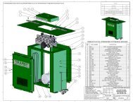
PARTS LIST: Motor & Arbor Assembly (HPS67 Horiz. <strong>Panel</strong> <strong>Saw</strong>)<br />
No. Part No. Description Quantity<br />
Φ<br />
1 HPS67-101 Collar ........................................................................................................1<br />
2 HPS67-102 Arbor Shaft................................................................................................1<br />
3 HPS67-103 Shaft .........................................................................................................1<br />
4 HPS67-104 Bushing.....................................................................................................1<br />
5 HPS67-105 Retainer Ring............................................................................................1<br />
6 HPS67-106 Bracket .....................................................................................................1<br />
7 HPS67-107 Retainer Block...........................................................................................1<br />
8 HPS67-108 Spacer ......................................................................................................1<br />
9 HPS67-109 Sleeve ......................................................................................................1<br />
10 HPS67-110 Motor Base................................................................................................1<br />
11 HPS67-111 Flange Washer..........................................................................................1<br />
12 HPS67-112 V-Belt........................................................................................................2<br />
13 HPS67-113 Arbor Pulley ..............................................................................................1<br />
14 HPS67-114 Shaft .........................................................................................................1<br />
15 HPS67-115 Hose Clamp ..............................................................................................3<br />
16 HPS67-116 Riving Knife Holder Plate ..........................................................................1<br />
17 HPS67-117 Spacer ......................................................................................................1<br />
18 HPS67-118 Strap Bracket ............................................................................................1<br />
19 HPS67-119 Flange Nut Height Adjustment...................................................................2<br />
20 HPS67-120 Spacer ......................................................................................................2<br />
21 HPS67-121 spacer.......................................................................................................1<br />
22 HPS67-122 Nut Inclination ...........................................................................................2<br />
23 HPS67-123 Motor Pulley..............................................................................................1<br />
24 HPS67-124 Bracket .....................................................................................................1<br />
25 HPS67-125 Bracket .....................................................................................................1<br />
26 HPS67-126 Riving Knife 250/300.................................................................................1<br />
27 HPS67-127 Bracket .....................................................................................................1<br />
31 ---------------- <strong>Saw</strong> Blade (not included)...........................................................................1<br />
32 HPS67-132 Spring .......................................................................................................1<br />
33 HPS67-133 Handwheel ................................................................................................1<br />
34 HPS67-134 Pin, 4 x 24mm.......................................................................................1<br />
35 HPS67-135 Handwheel Mouting Handle.......................................................................1<br />
36 HPS67-136 Handwheel ................................................................................................2<br />
37 HPS67-137 Collar ........................................................................................................1<br />
38 HPS67-138 Stud, M8 x 60............................................................................................1<br />
39 HPS67-139 Bushing.....................................................................................................2<br />
40 HPS67-140 Spindle......................................................................................................1<br />
41 HPS67-141 Plate .........................................................................................................1<br />
42 HPS67-142 Mount Bracket...........................................................................................1<br />
43 HPS67-143 Spindle Bracket.........................................................................................1<br />
44 HPS67-144 Spindle......................................................................................................1<br />
45 HPS67-145 Cover Tube...............................................................................................1<br />
46 HPS67-146 Plate .........................................................................................................2<br />
47 HPS67-147 Plate .........................................................................................................1<br />
48 HPS67-148 Handle ......................................................................................................1<br />
49 HPS67-149 Strap Bracket ............................................................................................1<br />
50 HPS67-150 Tube .........................................................................................................1<br />
51 HPS67-151 Sleeve ......................................................................................................1<br />
52 BB-6003ZZ Ball Bearing ..............................................................................................2<br />
53 HPS67-153 Stud, M12 x 50..........................................................................................2<br />
54 HPS67-154 Motor, 5HP, 3Ph, 230V .............................................................................1<br />
55 HPS67-155 Bolt Handwheel .........................................................................................1<br />
56 HPS67-156 Bracket .....................................................................................................1<br />
27
PARTS LIST: Motor & Arbor Assembly (HPS67 Horiz. <strong>Panel</strong> <strong>Saw</strong>) continued<br />
No. Part No. Description Quantity<br />
57 TS-1504051 Socket Head Cap Screw, M8 x 25 ............................................................ 1<br />
58 TS-1504041 Socket Head Cap Screw, M8 x 20 ............................................................ 5<br />
60 TS-1541031 Nylon Lock Hex Nut, M8 ........................................................................... 2<br />
61 TS-1490031 Hex Head Cap Screw, M8 x 20................................................................. 1<br />
62 TS-1540061 Full Hex Nut, M8....................................................................................... 6<br />
63 TS-2238751 Socket Head Cap Screw, M8 x 75 ............................................................ 1<br />
64 TS-1504131 Socket Head Cap Screw, M8 x 70 ............................................................ 2<br />
65 TS-2239101 Socket Head Cap Screw, M10 x 8 ............................................................ 1<br />
66 TS-1505011 Socket Head Cap Screw, M10 x 16........................................................... 2<br />
67 HPS67-157 Flange Washer ......................................................................................... 1<br />
68 TS-2360101 Flat Washer, M12 ..................................................................................... 2<br />
69 TS-2342121 Full Nylon Inset Lock Nut, M12 ................................................................. 2<br />
70 TS-1490041 Hex Cap Screw, M8 x 25 .......................................................................... 4<br />
71 TS-2312241 Hex Jam Nut, M24.................................................................................... 4<br />
72 TS-1504011 Socket Head Cap Screw, M8 x 10 ............................................................ 1<br />
73 TS-1516031 Flat Head Socket Cap Screw, M10 x 30.................................................... 1<br />
74 TS-1506051 Socket Head Cap Screw, M12 x 40........................................................... 1<br />
75 TS-1524011 Socket Set Screw, M8 x 8......................................................................... 4<br />
76 TS-1490061 Hex Head Cap Screw, M8 x 35................................................................. 1<br />
77 TS-2361081 Lock Washer, M8...................................................................................... 1<br />
78 TS-1524041 Socket Set Screw, M8 x 16....................................................................... 2<br />
79 TS-1490081 Hex Head Cap Screw, M8 x 45................................................................. 3<br />
80 TS-1514051 Flat Head Socket Cap Screw, M6 x 30...................................................... 1<br />
81 TS-1541021 Nylon Lock Hex Nut, M6 ........................................................................... 1<br />
82 TS-1550041 Flat Washer, M6....................................................................................... 1<br />
83 HPS67-158 Dado Bushing, 30mm ............................................................................... 1<br />
84 TS-1522061 Socket Set Screw, M5 x 20....................................................................... 2<br />
28
PART LIST: Motor & Arbor Assembly (HPS67 Horiz. <strong>Panel</strong> <strong>Saw</strong>)<br />
29
PARTS LIST: Scoring Motor & Arbor Assembly (HPS67 Horiz. <strong>Panel</strong> <strong>Saw</strong>)<br />
No. Part No. Description Quantity<br />
1 HPS67-201 Collar........................................................................................................ 1<br />
2 --------------- Scoring Blade (not included)..................................................................... 1<br />
3 HPS67-203 Arbor Shaft ............................................................................................... 1<br />
4 HPS67-204 Bushing .................................................................................................... 1<br />
5 HPS67-205 Sleeve...................................................................................................... 1<br />
6 HPS67-206 V-Belt ....................................................................................................... 1<br />
7 HPS67-207 Arbor Pulley.............................................................................................. 1<br />
8 HPS67-208 Tilt Bracket ............................................................................................... 2<br />
9 HPS67-209 Lever Assembly........................................................................................ 1<br />
10 HPS67-210 Lever Plate............................................................................................... 1<br />
11 HPS67-211 Micro Switch............................................................................................. 1<br />
12 HPS67-212 Mounting Bracket...................................................................................... 1<br />
13 HPS67-213 Spacer...................................................................................................... 2<br />
14 HPS67-214 Handle Knob............................................................................................. 1<br />
15 HPS67-215 Bushing .................................................................................................... 1<br />
16 HPS67-216 Cover ....................................................................................................... 1<br />
17 HPS67-217 Bracket ..................................................................................................... 1<br />
18 HPS67-218 Adjustment Screw..................................................................................... 1<br />
19 HPS67-219 Block ........................................................................................................ 1<br />
20 HPS67-220 Arbor Housing........................................................................................... 1<br />
21 HPS67-221 Shaft......................................................................................................... 1<br />
22 HPS67-222 Shaft Guide .............................................................................................. 1<br />
23 HPS67-223 Shaft Bracket............................................................................................ 1<br />
24 HPS67-224 Guide Bracket........................................................................................... 1<br />
25 HPS67-225 Spring....................................................................................................... 1<br />
26 HPS67-226 Motor Pulley ............................................................................................. 1<br />
27 HPS67-227 Strap Bracket............................................................................................ 1<br />
28 HPS67-228 Bushing .................................................................................................... 1<br />
29 HPS67-229 Hose......................................................................................................... 1<br />
30 HPS67-230 Hose Clamp.............................................................................................. 1<br />
31 HPS67-231 Dust Chute ............................................................................................... 1<br />
32 HPS67-232 <strong>Saw</strong> Unit Assembly................................................................................... 1<br />
33 HPS67-233 Scoring Motor, 3/4HP, 230V ..................................................................... 1<br />
34 HPS67-234 Lever Bracket ........................................................................................... 1<br />
35 BB-6003ZZ Ball Bearing, 6003ZZ................................................................................ 2<br />
36 BB-608ZZ Ball Bearing, 608ZZ.................................................................................. 2<br />
37 TS-1504041 Socket Head Cap Screw, M8 x 20 ............................................................ 1<br />
38 TS-1515021 Flat Head Socket Cap Screw, M8 x 20...................................................... 1<br />
39 TS-1515031 Flat Head Socket Cap Screw, M8 x 25...................................................... 1<br />
40 TS-1515011 Flat Head Socket Cap Screw, M8 x 16...................................................... 1<br />
41 TS-2248162 Socket Head Button Screw, M8 x 16......................................................... 2<br />
42 TS-1550041 Flat Washer, M6....................................................................................... 3<br />
43 TS-1550061 Flat Washer, M8....................................................................................... 8<br />
44 TS-2311061 Hex Nut, M6 ............................................................................................. 1<br />
45 TS-2311081 Hex Nut, M8 ............................................................................................. 2<br />
46 TS-1490041 Hex Head Cap Screw, M8 x 25................................................................. 1<br />
47 TS-1482031 Hex Head Cap Screw, M6 x 16................................................................. 1<br />
48 TS-1501081 Socket Head Cap Screw, M4 x 30 ............................................................ 1<br />
49 TS-2361061 Split Lock Washer, M6.............................................................................. 2<br />
50 TS-1541021 Nylon Lock Hex Nut.................................................................................. 2<br />
51 TS-1490031 Hex Head Cap Screw, M8 x 20................................................................. 2<br />
52 TS-1490021 Hex Head Cap Screw, M8 x 16................................................................. 2<br />
53 TS-2310162 Hex Nut, M16 ........................................................................................... 1<br />
54 TS-1522041 Socket Set Screw, M5 x 12....................................................................... 1<br />
55 TS-1504021 Socket Head Cap Screw, M8 x 12 ............................................................ 2<br />
56 TS-1524031 Socket Set Screw, M8 x 12....................................................................... 1<br />
30
PARTS LIST: Scoring Motor & Arbor Assembly (HPS67 Horiz. <strong>Panel</strong> <strong>Saw</strong>)<br />
No. Part No. Description Quantity<br />
57 TS-1503131 Socket Head Cap Screw, M6 x 60.............................................................1<br />
58 TS-1490011 Hex Head Cap Screw, M8 x 12 .................................................................1<br />
31
PARTS LIST: Stand & Table Assembly (HPS67 Horiz. <strong>Panel</strong> <strong>Saw</strong>)<br />
No. Part No. Description Quantity<br />
1 HPS67-301 Stand........................................................................................................ 1<br />
2 HPS67-302 Table Extension........................................................................................ 1<br />
3 HPS67-303 Support Leg.............................................................................................. 1<br />
4 HPS67-304 Table ........................................................................................................ 1<br />
5 HPS67-305 Table <strong>Saw</strong> Extension Right Z.................................................................... 1<br />
6 HPS67-306 Door ......................................................................................................... 1<br />
7 HPS67-307 Dust Chute ............................................................................................... 1<br />
8 HPS67-308 Base Plate................................................................................................ 1<br />
9 HPS67-309 Base Plate................................................................................................ 1<br />
10 HPS67-310 Base Plate................................................................................................ 1<br />
11 HPS67-311 Hook......................................................................................................... 1<br />
12 HPS67-312 Threaded Rod........................................................................................... 1<br />
13 HPS67-313 Bushing .................................................................................................... 1<br />
14 HPS67-314 Spacer Block ............................................................................................ 1<br />
15 HPS67-315 Mount Plate .............................................................................................. 1<br />
16 HPS67-316 Mount Block.............................................................................................. 1<br />
17 HPS67-317 Spacer Block ............................................................................................ 1<br />
18 HPS67-318 Bushing .................................................................................................... 1<br />
19 HPS67-319 Mount Plate .............................................................................................. 1<br />
20 HPS67-320 Housing .................................................................................................... 1<br />
21 HPS67-321 Bushing .................................................................................................... 1<br />
22 HPS67-322 Side Plate................................................................................................. 1<br />
23 HPS67-323 Bracket ..................................................................................................... 1<br />
24 HPS67-324 Spring....................................................................................................... 1<br />
25 HPS67-325 Box........................................................................................................... 1<br />
26 HPS67-326 Rod .......................................................................................................... 1<br />
27 HPS67-327 Wrench..................................................................................................... 1<br />
28 HPS67-328 Wrench, 12 x 17mm ................................................................................. 1<br />
29 TS-152707 Hex Wrench, 6mm Short .......................................................................... 1<br />
30 TS-152706 Hex Wrench, 5mm Short .......................................................................... 1<br />
31 TS-152705 Hex Wrench, 4mm Short .......................................................................... 1<br />
32 TS-1550041 Flat Washer, M6....................................................................................... 1<br />
33 TS-2311061 Hex Nut, M6 ............................................................................................. 1<br />
34 TS-1514021 Socket Head Flat Screw, M6 x 16............................................................. 1<br />
35 TS-1490031 Hex Cap Screw, M8 x 20 .......................................................................... 1<br />
36 TS-1550061 Flat Washer, M8....................................................................................... 6<br />
37 TS1504031 Socket Head Cap Screw, M8 x 16 ............................................................ 1<br />
38 TS-1504041 Socket Head Cap Screw, M8 x 20 ............................................................ 1<br />
39 TS-2361081 Lock Washer, M8...................................................................................... 3<br />
40 TS-1503041 Socket Head Cap Screw, M6 x 16 ............................................................ 1<br />
41 TS-2248501 Socket Head Flat Screw, M8 x 50............................................................. 2<br />
42 TS-1504101 Socket Head Cap Screw, M8 x 50 ............................................................ 2<br />
43 TS-1490011 Hex Head Cap Screw, M8 x 12................................................................. 1<br />
44 TS-1482021 Hex Head Cap Screw, M8 x 12................................................................. 1<br />
45 TS-2311081 Hex Nut, M8 ............................................................................................. 2<br />
46 TS-2311061 Hex Nut, M6 ............................................................................................. 1<br />
47 TS-1504071 Socket Head Cap Screw, M8 x 35 ............................................................ 1<br />
48 TS-1503011 Socket Head Cap Screw, M6 x 8 .............................................................. 1<br />
49 TS-1550061 Flat Washer, M8....................................................................................... 1<br />
50 TS-1490151 Hex Head Cap Screw, M8 x 80................................................................. 2<br />
51 TS-1515051 Flat Head Socket Cap Screw, M8 x 40...................................................... 1<br />
52 TS-154010 Hex Nut, M16 ........................................................................................... 8<br />
53 TS-155010 Flat Washer, M16 ..................................................................................... 8<br />
54 TS-1490101 Hex Head Cap Screw, M8 x 55................................................................. 1<br />
55 TS-1490041 Hex Cap Screw, M8 x 25 .......................................................................... 4<br />
32
Stand & Table Assembly (HPS67 Horiz. <strong>Panel</strong> <strong>Saw</strong>)<br />
33
PARTS LIST: Sliding Table Assembly (HPS67 Horiz. <strong>Panel</strong> <strong>Saw</strong>)<br />
No. Part No. Description Quantity<br />
1 HPS67-401 Plate......................................................................................................... 1<br />
2 HPS67-402 Mount Plate .............................................................................................. 1<br />
3 HPS67-403 Steel Ball................................................................................................ 30<br />
4 HPS67-404 Plug.......................................................................................................... 4<br />
5 HPS67-405 Wiper ....................................................................................................... 4<br />
6 HPS67-406 Plate (1700).............................................................................................. 1<br />
7 HPS67-407 Cover Plate .............................................................................................. 2<br />
8 HPS67-408 Strap Plate ............................................................................................... 1<br />
9 HPS67-409 Adjustment Knob ...................................................................................... 1<br />
10 HPS67-410 Adjustment Block...................................................................................... 1<br />
11 HPS67-411 Lock Plate ................................................................................................ 1<br />
12 HPS67-412 Mitre Guide Stop ...................................................................................... 1<br />
13 HPS67-413 Profile Tube.............................................................................................. 1<br />
15 HPS67-415 Handle...................................................................................................... 1<br />
18 HPS67-418 Plate......................................................................................................... 2<br />
19 HPS67-419 Lock Profile .............................................................................................. 2<br />
20 HPS67-420 Lock Plate ................................................................................................ 2<br />
21 HPS67-421 Lock Block................................................................................................ 2<br />
22 HPS67-422 Profile Support (1700)............................................................................... 1<br />
23 HPS67-423 Lock Slide Table....................................................................................... 1<br />
24 HPS67-424 Spring....................................................................................................... 1<br />
25 HPS67-425 Rod (1700) ............................................................................................... 8<br />
26 HPS67-426 Clamp Pin................................................................................................. 1<br />
27 HPS67-427 Rubber Buffer Plate.................................................................................. 1<br />
28 HPS67-428 Spacer...................................................................................................... 1<br />
29 HPS67-429 Nut Plate ................................................................................................ 14<br />
30 HPS67-129 Handle...................................................................................................... 2<br />
31 HPS67-431 Handle Plate............................................................................................. 1<br />
32 HPS67-432 Clamp Plate.............................................................................................. 2<br />
33 HPS67-433 Profile Support Table (1700)..................................................................... 1<br />
34 HPS67-434 Nut Plate .................................................................................................. 1<br />
35 HPS67-435 Clamp....................................................................................................... 1<br />
36 HPS67-436 Stop Plate................................................................................................. 1<br />
37 HPS67-437 Mount Plate (1700) ................................................................................... 1<br />
38 HPS67-438 Handle Bolt............................................................................................... 2<br />
39 HPS67-439 Bushing .................................................................................................... 1<br />
40 HPS67-440 Handle...................................................................................................... 1<br />
41 HPS67-441 Wing Bolt.................................................................................................. 2<br />
42 HPS67-442 Post Block ................................................................................................ 1<br />
43 HPS67-443 Rod .......................................................................................................... 1<br />
44 HPS67-444 Post.......................................................................................................... 1<br />
45 HPS67-445 Handle...................................................................................................... 1<br />
46 HPS67-446 Clamp Block ............................................................................................. 1<br />
47 HPS67-447 Clamp....................................................................................................... 1<br />
48 HPS67-448 Handle Rod .............................................................................................. 1<br />
49 HPS67-449 Cam ......................................................................................................... 1<br />
50 HPS67-450 Stud, M10 x 20 ......................................................................................... 4<br />
51 TS-1490021 Hex Head Cap Screw, M8 x 16................................................................. 1<br />
52 TS-1491041 Hex Head Cap Screw, M10 x 30............................................................... 1<br />
53 TS-1550071 Flat Washer, M10 ..................................................................................... 1<br />
54 TS-1550061 Flat Washer, M8..................................................................................... 10<br />
55 TS-2311081 Hex Nut, M8 ............................................................................................. 4<br />
34
PARTS LIST: Sliding Table Assembly (HPS67 Horiz. <strong>Panel</strong> <strong>Saw</strong>) continued<br />
No. Part No. Description Quantity<br />
57 TS-2360121 Flat Washer, M12......................................................................................2<br />
58 TS-1540081 Hex Nut, M12............................................................................................2<br />
59 TS-1541021 Nylon Lock Hex Nut, M6............................................................................4<br />
62 TS-1482031 Hex Head Cap Screw, M6 x 16 .................................................................6<br />
63 TS-1504101 Socket Head Cap Screw, M8 x 50.............................................................2<br />
64 TS-1504121 Socket Head Cap Screw, M8 x 60.............................................................2<br />
65 TS-1550061 Flat Washer, M8 .......................................................................................1<br />
66 TS-1541031 Nylon Lock Hex Nut, M8............................................................................2<br />
67 HPS67-451 Stud, M8 x 20............................................................................................6<br />
68 HPS67-452 Self Tapping Screw...................................................................................4<br />
69 TS-1524031 Socket Set Screw, M8 x 12 .......................................................................2<br />
70 TS-1515031 Flat Head Socket Cap Screw, M8 x 25 ......................................................1<br />
71 TS-1504031 Socket Head Cap Screw, M8 x 16...........................................................14<br />
72 HPS67-453 Washer .....................................................................................................1<br />
73 TS-1504041 Socket Head Cap Screw, M8 x 20.............................................................5<br />
74 TS-1490071 Hex Head Cap Screw, M8 x 40 .................................................................1<br />
75 TS-1491061 Hex Head Cap Screw, M10 x 40 ...............................................................1<br />
76 TS-2361141 Lock Washer, M14 ....................................................................................1<br />
77 TS-2311081 Hex Nut, M8..............................................................................................2<br />
78 TS-2311101 Hex Nut, M10............................................................................................1<br />
35
Sliding Table Assembly (HPS67 Horiz. <strong>Panel</strong> <strong>Saw</strong>)<br />
36
PARTS LIST: Support Arm Assembly (HPS67 Horiz. <strong>Panel</strong> <strong>Saw</strong>)<br />
No. Part No. Description Quantity<br />
1 HPS67-501 Support Arm..............................................................................................1<br />
2 HPS67-502 Shaft .........................................................................................................1<br />
3 HPS67-503 Shaft .........................................................................................................1<br />
4 HPS67-504 Side Plate .................................................................................................1<br />
5 HPS67-505 Roller ........................................................................................................1<br />
6 HPS67-506 Plug ..........................................................................................................2<br />
7 HPS67-507 Arm Tube..................................................................................................1<br />
8 HPS67-508 Brush ........................................................................................................4<br />
9 HPS67-509 Bracket .....................................................................................................1<br />
10 HPS67-510 Bracket .....................................................................................................1<br />
11 HPS67-511 Arm Bracket ..............................................................................................1<br />
12 HPS67-512 Pivot Shaft ................................................................................................1<br />
13 HPS67-513 Spacer ......................................................................................................1<br />
14 HPS67-514 Spool ........................................................................................................1<br />
15 HPS67-515 Shaft .........................................................................................................1<br />
16 BB-6003ZZ Ball Bearing, 6003ZZ ................................................................................2<br />
17 TS-154010 Hex Nut, M16............................................................................................1<br />
18 TS-1503031 Socket Head Cap Screw, M6 x 12.............................................................8<br />
19 TS-1550041 Flat Washer, M6 .......................................................................................8<br />
20 HPS67-516 Retainer Ring............................................................................................1<br />
21 TS-2311081 Hex Nut, M8..............................................................................................5<br />
22 TS-1550061 Flat Washer, M8 .......................................................................................6<br />
23 TS-1490021 Hex Head Cap Screw, M8 x 16 .................................................................4<br />
24 TS-2213801 Hex Head Cap Screw, M16 x 80 ...............................................................1<br />
25 TS-155010 Flat Washer, M16......................................................................................1<br />
26 TS-1504031 Socket Head Cap Screw, M8 x 16.............................................................4<br />
27 TS-1503041 Socket Head Cap Screw, M6 x 16.............................................................1<br />
28 TS-1524061 Socket Set Screw, M8 x 25 .......................................................................1<br />
29 TS-2210161 Hex Head Cap Screw, M10 x 16 ...............................................................1<br />
30 TS-1550071 Flat Washer, M10......................................................................................2<br />
31 TS-1523061 Socket Set Screw, M6 x 20 .......................................................................1<br />
32 TS-1504021 Socket Head Cap Screw, M8 x 12.............................................................1<br />
37
Support Arm Assembly (HPS67 Horiz. <strong>Panel</strong> <strong>Saw</strong>)<br />
38
PARTS LIST: Cross Cut Fence Assembly (HPS67 Horiz. <strong>Panel</strong> <strong>Saw</strong>)<br />
No. Part No. Description Quantity<br />
1 HPS67-601 Cross Cut Fence .......................................................................................1<br />
2 HPS67-129 Handle ......................................................................................................1<br />
3 HPS67-603 Flipper Bracket (Left) ................................................................................2<br />
4 HPS67-604 Pin ............................................................................................................2<br />
5 HPS67-605 Bracket Cursor ..........................................................................................2<br />
6 HPS67-606 Flipper Bracket (Right) ..............................................................................2<br />
7 HPS67-607 Stop Bushing.............................................................................................4<br />
8 HPS67-608 Fence Tube...............................................................................................1<br />
9 HPS67-609 T-Bolt........................................................................................................1<br />
10 HPS67-610 Fence Clamp ............................................................................................1<br />
11 HPS67-611 Plate .........................................................................................................1<br />
12 HPS67-612 Mitre Bracket.............................................................................................1<br />
13 HPS67-613 Hand Knob................................................................................................1<br />
14 HPS67-614 Square Nut................................................................................................1<br />
15 HPS67-615 Washer .....................................................................................................2<br />
16 HPS67-616 Bracket .....................................................................................................2<br />
17 HPS67-617 Clamp Nut.................................................................................................1<br />
18 HPS67-618 Hand Knob................................................................................................1<br />
19 HPS67-619 Lock Knob.................................................................................................1<br />
20 HPS67-620 Clamp .......................................................................................................1<br />
21 HPS67-621 Strap Bracket ............................................................................................1<br />
22 HPS67-622 Adjustment Plate.......................................................................................1<br />
23 HPS67-623 Bracket .....................................................................................................1<br />
24 HPS67-624 Bracket .....................................................................................................1<br />
25 HPS67-625 Fence Splitter Protector ............................................................................1<br />
26 HPS67-626 Self-Tapping Screw...................................................................................1<br />
27 TS-1541031 Hex Nylon Lock Nut, M8............................................................................2<br />
28 TS-1504091 Socket Head Cap Screw, M8 x 45.............................................................2<br />
29 TS-1523031 Socket Set Screw, M6 x 10 .......................................................................1<br />
30 TS-1550041 Flat Washer, M6 .......................................................................................1<br />
31 TS-1482031 Hex Head Cap Screw, M6 x 16 .................................................................1<br />
32 TS-1550041 Flat Washer, M6 .......................................................................................2<br />
33 TS-1541021 Hex Nylon Lock Nut, M6............................................................................2<br />
34 TS-2210161 Hex Head Cap Screw, M10 x 16 ...............................................................1<br />
35 TS-1482061 Hex Head Cap Screw, M6 x 30 .................................................................2<br />
36 TS-1550071 Flat Washer, M10......................................................................................2<br />
37 TS-1524011 Socket Set Screw, M8 x 8 .........................................................................2<br />
38 TS-2361081 Lock Washer, M8 ......................................................................................1<br />
39 HPS67-627 Cross Tube ...............................................................................................1<br />
40 HPS67-628 Handle ......................................................................................................1<br />
41 TS-1550071 Flat Washer, M10......................................................................................1<br />
42 TS-1490011 Hex Head Cap Screw, M8 x 12 .................................................................1<br />
43 TS-1550061 Flat Washer, M8 .......................................................................................1<br />
44 TS-1523011 Socket Set Screw, M6 x 6 .........................................................................2<br />
45 TS-2246101 Flat Head Socket Cap Screw, M6 x 10 ......................................................1<br />
39
Cross Cut Fence Assembly (HPS67 Horiz. <strong>Panel</strong> <strong>Saw</strong>)<br />
40
PARTS LIST: Rip Fence Assembly (HPS67 Horiz. <strong>Panel</strong> <strong>Saw</strong>)<br />
No. Part No. Description Quantity<br />
1 HPS67-445 Handle ......................................................................................................2<br />
2 HPS67-702 Stud ..........................................................................................................2<br />
3 HPS67-703 Lock Bushing ............................................................................................1<br />
4 HPS67-704 Bushing.....................................................................................................1<br />
5 HPS67-705 Sleeve ......................................................................................................1<br />
6 HPS67-706 Fence Bracket...........................................................................................1<br />
7 HPS67-707 Spacer ......................................................................................................2<br />
8 HPS67-708 Fence........................................................................................................1<br />
9 HPS67-709 Strap.........................................................................................................1<br />
10 HPS67-710 Stud ..........................................................................................................2<br />
11 HPS67-711 Guide Bar..................................................................................................1<br />
12 HPS67-712 Collar ........................................................................................................1<br />
13 HPS67-713 Spacer ......................................................................................................1<br />
14 HPS67-714 Parallel Scale............................................................................................1<br />
21 HPS67-721 Plate .........................................................................................................1<br />
22 HPS67-722 Adjustment Bracket ...................................................................................1<br />
23 HPS67-723 Bushing.....................................................................................................1<br />
24 HPS67-724 Bar............................................................................................................1<br />
25 HPS67-725 Guide Bolt.................................................................................................1<br />
26 HPS67-726 Adjustment Lock Bolt ................................................................................1<br />
27 HPS67-727 Handle Plate .............................................................................................1<br />
28 HPS67-728 Fine Adjustment Bolt.................................................................................1<br />
29 HPS67-729 Retainer Ring............................................................................................2<br />
30 HPS67-730 Eccentric Shaft..........................................................................................1<br />
31 HPS67-731 Lock Collar................................................................................................1<br />
32 TS-1540081 Hex Nut, M12............................................................................................4<br />
33 TS-2360121 Flat Washer, M12......................................................................................4<br />
34 TS-1504041 Socket Head Cap Screw, M8 x 20.............................................................1<br />
35 TS-154010 Hex Nut, M16............................................................................................1<br />
36 TS-2235601 Socket Head Cap Screw, M5 x 60.............................................................2<br />
38 TS-1490071 Hex Head Cap Screw, M8 x 40 .................................................................1<br />
43 TS-1504061 Socket Head Cap Screw, M8 x 30.............................................................5<br />
44 TS-1524011 Socket Set Screw, M8 x 8 .........................................................................1<br />
45 TS-1524031 Socket Set Screw, M8 x 12 .......................................................................1<br />
46 TS-1524051 Socket Set Screw, M8 x 20 .......................................................................1<br />
47 TS-1550061 Flat Washer, M8 .......................................................................................2<br />
48 TS-1490061 Hex Head Cap Screw, M8 x 35 .................................................................1<br />
41
Rip Fence Assembly (HPS67 Horiz. <strong>Panel</strong> <strong>Saw</strong>)<br />
42
PARTS LIST: Over Arm Guard Assembly (HPS67 <strong>Horizontal</strong> <strong>Panel</strong> <strong>Saw</strong>)<br />
No. Part No. Description Quantity<br />
1 HPS67-901 Frame .......................................................................................................1<br />
2 HPS67-902 Guard........................................................................................................1<br />
3 HPS67-903 Support Strap............................................................................................1<br />
4 HPS67-904 Pointer ......................................................................................................1<br />
5 HPS67-445 Handle ......................................................................................................1<br />
6 HPS67-906 Bushing.....................................................................................................4<br />
7 HPS67-907 Bracket .....................................................................................................1<br />
8 HPS67-129 Handle ......................................................................................................3<br />
9 HPS67-909 Hand Knob................................................................................................1<br />
10 HPS67-910 End Cap....................................................................................................2<br />
11 HPS67-911 End Cap....................................................................................................1<br />
12 HPS67-912 Height Plate ..............................................................................................1<br />
13 HPS67-913 Bushing.....................................................................................................1<br />
14 HPS67-914 Washer .....................................................................................................1<br />
15 HPS67-915 Bracket .....................................................................................................1<br />
16 HPS67-916 Clamp .......................................................................................................2<br />
17 HPS67-917 Dust Chute................................................................................................1<br />
18 HPS67-918 Back Plate.................................................................................................1<br />
19 HPS67-919 Brace ........................................................................................................1<br />
20 HPS67-920 Nut............................................................................................................2<br />
21 HPS67-921 Guard........................................................................................................1<br />
22 HPS67-922 Brace ........................................................................................................1<br />
23 HPS67-923 Wood Frame.............................................................................................2<br />
24 HPS67-924 Plexi Glass Guard .....................................................................................2<br />
25 HPS67-925 Cover........................................................................................................1<br />
26 TS-1524061 Socket Set Screw, M8 x 25 .......................................................................2<br />
27 TS-1550061 Flat Washer, M8 .......................................................................................8<br />
28 TS-1503011 Socket Head Cap Screw, M6 x 8...............................................................4<br />
29 TS-1505041 Socket Head Cap Screw, M10 x 30 ...........................................................4<br />
30 TS-1550071 Flat Washer, M10......................................................................................6<br />
31 TS-2311101 Hex Nut, M10............................................................................................4<br />
32 TS-2311081 Hex Nut, M8..............................................................................................6<br />
33 HPS67-933 Self Tapping Screw, 8 x 1/2 ....................................................................12<br />
34 TS-2208901 Hex Cap Screw, M8 x 90...........................................................................2<br />
35 TS-1515021 Flat Head Socket Cap Screw, M8 x 20 ......................................................2<br />
36 TS-1541021 Nylon Lock Hex Nut, M6............................................................................1<br />
37 TS-1541031 Nylon Lock Hex Nut, M8............................................................................2<br />
38 TS-1550041 Flat Washer, M6 .......................................................................................1<br />
39 TS-1490021 Hex Head Cap Screw, M8 x 16 .................................................................2<br />
40 TS-2208751 Hex Head Cap Screw, M8 x 100 ...............................................................1<br />
41 TS-2208751 Hex Head Cap Screw, M8 x 75 .................................................................1<br />
42 TS-2206701 Hex Head Bolt, M6 x 70 ............................................................................1<br />
43 TS-1541031 Nylon Lock Hex Nut, M8............................................................................2<br />
44 TS-2360121 Flat Washer, M12......................................................................................3<br />
45 TS-1491021 Hex Head Cap Screw, M10 x 20 ...............................................................1<br />
43
Over Arm Guard Assembly (HPS67 <strong>Horizontal</strong> <strong>Panel</strong> <strong>Saw</strong>)<br />
44
Electrical Components (HPS67 <strong>Horizontal</strong> <strong>Panel</strong> <strong>Saw</strong>)<br />
No. Part No. Description Quantity<br />
1 HPS67-801 Main Switch ..............................................................................................1<br />
2 HPS67-802 Fuse, 10 x 38mm (3.7kw 230V 3Ph 16A) ..................................................3<br />
5 HPS67-805 Fuse, 6 x 20mm (0.5A Primary Transformer AM) ......................................1<br />
6 HPS67-806 Fuse, 6 x 20mm (2A Secondary Transformer GL) .....................................1<br />
7 HPS67-807 Fuse Holder ..............................................................................................1<br />
8 HPS67-808 Transformer 230-400-24V 40VA................................................................1<br />
9 HPS67-809 Thermal Overload (9-13A 230V 3.7kw) .....................................................1<br />
10 HPS67-810 Thermal Overload (2.8-4.4A 230V, 55kw) .................................................1<br />
11 HPS67-811 Emergency Stop Frame ............................................................................1<br />
12 HPS67-812 Emergency Stop Electrical Cabinet ...........................................................1<br />
13 HPS67-813 Micro Switch <strong>Saw</strong> Cover ...........................................................................1<br />
14 HPS67-814 Start (<strong>Saw</strong> Motor)......................................................................................1<br />
15 HPS67-815 Start (Scoring Motor).................................................................................1<br />
16 HPS67-816 Star-Delta Switch (3.7kw)..........................................................................1<br />
17 HPS67-817 Magnetic Starter (3.7kw 230V AB-C12) <strong>Saw</strong> Motor ...................................1<br />
18 HPS67-818 Magnetic Starter (.55kw 230V AB-C12) Scoring Motor ..............................1<br />
45
ELECTRICAL SCHEMATIC (HPS67 <strong>Horizontal</strong> <strong>Panel</strong> <strong>Saw</strong>)<br />
46
To order parts or reach our service department, please call our toll-free number between 7:00 a.m. and 6:00 p.m.<br />
(CST), Monday through Friday. Having the Model Number and Serial Number of your machine available when you<br />
call will allow us to serve you quickly and accurately. Locating the stock number of the part(s) required from your<br />
parts manual will also expedite your order.<br />
Phone No.: (800) 274-6848<br />
Website: www.wmhtoolgroup.com<br />
47
48<br />
WMH <strong>Tool</strong> Group<br />
2420 Vantage Drive<br />
Elgin, Illinois 60123<br />
Phone: 800-274-6848<br />
www.wmhtoolgroup.com