MTR-40F REV 0.p65 - Southern Tool
MTR-40F REV 0.p65 - Southern Tool
MTR-40F REV 0.p65 - Southern Tool
- No tags were found...

You also want an ePaper? Increase the reach of your titles
YUMPU automatically turns print PDFs into web optimized ePapers that Google loves.
OPERATION AND PARTS MANUALTamping RammerModel<strong>MTR</strong>-<strong>40F</strong>© COPYRIGHT 2003, MULTIQUIP INC.Revision #0 (01/21/04)MULTIQUIP INC. PARTS DEPARTMENT:18910 WILMINGTON AVE. 800-427-1244CARSON, CALIFORNIA 90746 FAX: 800-672-7877310-537-3700 SERVICE DEPARTMENT/TECHNICAL ASSISTANCE:800-421-1244 800-478-1244FAX: 310-537-3927 FAX: 310-631-5032E-mail:mq@multiquip.com • www:multiquip.comAtlanta • Boise • Dallas • Houston • NewarkMontreal, Canada • Manchester, UKRio De Janiero, Brazil • Guadalajara, Mexico
PAGE 2 — <strong>MTR</strong>-<strong>40F</strong>— PARTS & OPERATION MANUAL — <strong>REV</strong>. #0 (01/21/04)
HERE'S HOW TO GET HELPPLEASE HAVE THE MODEL AND SERIALNUMBER ON-HAND WHEN CALLINGMULTIQUIP’S MAIN PHONE NUMBERS800-421-1244 FAX: 310-537-3927310-537-3700PARTS DEPARTMENT800-427-1244 FAX: 800-672-7877310-537-3700 FAX: 310-637-3284MAYCO PARTS800-306-2926 FAX: 800-672-7877310-537-3700 FAX: 310-637-3284SERVICE DEPARTMENT800-478-1244 FAX: 310-537-4259310-537-3700MQ POWER SERVICE DEPARTMENT800-835-2551 FAX: 310-638-8046310-537-3700TECHNICAL ASSISTANCE800-478-1244 FAX: 310-631-5032WARRANTY DEPARTMENT800-421-1244, EXT. 279 FAX: 310-537-1173310-537-3700, EXT. 279<strong>MTR</strong>-<strong>40F</strong>— PARTS & OPERATION MANUAL — <strong>REV</strong>. #0 (01/21/04) — PAGE 3
TABLE OF CONTENTS<strong>MTR</strong>-<strong>40F</strong> TampingRammerHere's How To Get Help ............................................3Table Of Contents .....................................................4Parts Ordering Procedures .......................................5Safety Message Alert Symbols ............................. 6-7Rules For safe Operation ..................................... 8-9Operation and Safety Decals ..................................10General Information ................................................11Specifications ..........................................................12Controls and Components ......................................13Basic Engine ...........................................................14Pre-Inspection .........................................................15Initial Start-Up ................................................... 16-17Operation ................................................................18Maintenance (Rammer) .................................... 19-20Maintenance (Engine).............................................21Troubleshooting Guide ...................................... 22-23Explanation Of Codes In Remarks Column ............24Suggested Spare Parts ...........................................25Name Plate and Decals .................................... 26-27Crankcase and Engine Assembly ..................... 28-29Guide Cylinder Assembly .................................. 30-31Tank and Handle Assembly .............................. 32-35Foot Assembly .................................................. 36-37Narrow Foot Assembly (Option) ....................... 38-39Trench Shoe Assembly (Option) ....................... 40-41ROBIN EH-090D ENGINECrankcase and Cylinder Assembly ................... 42-43Crankshaft and Piston Assembly ...................... 44-45Governor Assembly .......................................... 46-47Muffler Assembly .............................................. 48-49Carburetor and Oil Pump Assembly ................. 50-51Recoil Starter & Blower Housing Assembly ..... 52-53Air Cleaner Assembly........................................ 54-55Carburetor Components Assembly .................. 56-57Recoil Starter Components Assembly .............. 58-59Magneto Assembly ........................................... 60-61Terms and Condition of Sale — Parts ......................... 62NOTESpecificationand part numberare subject tochange withoutnotice.PAGE 4 — <strong>MTR</strong>-<strong>40F</strong>— PARTS & OPERATION MANUAL — <strong>REV</strong>. #0 (01/21/04)
When ordering parts,please supply the following information:❒❒❒❒❒❒❒PARTS ORDERING PROCEDURESDealer account numberDealer name and addressShipping address (if different than billing address)Return fax numberApplicable model numberQuantity, part number and description of each partSpecify preferred method of shipment:✓ FedEx or UPS GroundNote: Unless otherwise indicated by customer, allorders are treated as “Standard Orders”, and will✓ FedEx or UPS Second Day or Third Dayship within 24 hours. We will make every effort to✓ FedEx or UPS Next Dayship “Air Shipments” the same day that the order is✓ Federal Express Priority Onereceived, if prior to 2PM west coast time. “Stock✓ DHLOrders” must be so noted on fax or web forms.✓ TruckHere’s how to get help...Please have the model and serial number onhand when calling.Place Your Parts Order Via Web or FaxFor Even More Savings!Parts Department800-427-1244 Fax: 800-672-7877310-537-3700 Fax: 310-637-3284Mayco Parts800-306-2926 Fax: 800-672-7877310-537-3700 Fax: 310-637-3284Service Department800-478-1244 Fax: 310-537-4259310-537-3700MQ Power Service Department800-835-2551 Fax: 310-638-8046310-537-3700Technical Assistance800-478-1244 Fax: 310-631-5032Warranty Department800-421-1244, Ext. 279 Fax: 310-537-1173310-537-3700, Ext. 279Multiquip’s Main Phone Numbers800-421-1244 Fax: 310-537-3927310-537-3700MULTIQUIP INC.18910 WILMINGTON AVENUEPOST OFFICE BOX 6254CARSON, CALIFORNIA 90749310-537-3700 • 800-421-1244FAX: 310-537-3927E-MAIL: mq@multiquip.comWWW: multiquip.comExtra Discounts!All parts orders which include complete part numbersand are received by our automated web parts ordersystem, or by fax qualify for the following extradiscounts:Ordered Standard Stock ordersvia orders ($750 list and above)Fax 3% 10%Web 5% 10%Special freight allowanceswhen you order 10 or moreline items via Web or Fax!**FedEx Ground Service at no charge for freightNo other allowances on freight shipped by any othercarrier.NOTE: DISCOUNTS ARE SUBJECT TO CHANGEDirect TOLL-FREE accessto our Parts Department:Toll-free nationwide — 800-427-1244<strong>MTR</strong>-<strong>40F</strong>— PARTS & OPERATION MANUAL — <strong>REV</strong>. #0 (01/21/04) — PAGE 5
<strong>MTR</strong>-<strong>40F</strong> — SAFETY MESSAGE ALERT SYMBOLSFOR YOUR SAFETY AND THE SAFETY OF OTHERS!Safety precautions should be followed at all times when operatingthis equipment. Failure to read and understand the SafetyMessages and Operating Instructions could result in injury toyourself and others.NOTESAFETY MESSAGE ALERT SYMBOLSThis Owner's Manual has beendeveloped to provide completeinstructions for the safe andefficient operation of the Multiquip<strong>MTR</strong>-<strong>40F</strong> Tamping Rammer. Referto the engine manufacturer'sinstructions for data relative to itssafe operation.Before using this Rammer,ensure that the operatingindividual has read andunderstands all instructions inthis manual.The three (3) Safety Messages shown below will inform youabout potential hazards that could injure you or others. TheSafety Messages specifically address the level of exposure tothe operator, and are preceded by one of three words: DANGER,WARNING, or CAUTION.HAZARD SYMBOLSExplosive FuelEngine exhaust gases contain poisonouscarbon monoxide. This gas is colorless andodorless, and can cause death if inhaled.NEVER operate this equipment in a confinedarea or enclosed structure that does notprovide ample free flow air.GASOLINE is extremely flammable, and itsvapors can cause an explosion if ignited. DONOT start the engine near spilled fuel orcombustible fluids. DO NOT fill the fuel tankwhile the engine is running or hot. DO NOToverfill tank, since spilled fuel could ignite if itcomes into contact with hot engine parts orsparks from the ignition system. Store fuel inapproved containers, in well-ventilated areasand away from sparks and flames. NEVERuse fuel as a cleaning agent.DANGER: You WILL be KILLED orSERIOUSLY injured if you do not followdirections.WARNING: You CAN be KILLED orSERIOUSLY injured if you do not followdirections.CAUTION: You CAN be injured if youdo not follow directions.Potential hazards associated with the <strong>MTR</strong>-<strong>40F</strong> TampingRammer operation will be referenced with Hazard Symbolswhich appear throughout this manual, and will be referenced inconjunction with Safety Message Alert Symbols.Burn HazardsEngine components can generate extreme heat.To prevent burns, DO NOT touch these areaswhile the engine is running or immediately afteroperations. Never operate the engine with heatshields or heat guards removed.Rotating PartsNEVER operate equipment with covers, orguards removed. Keep fingers, hands, hair andclothing away from all moving parts to preventinjury.PAGE 6 — <strong>MTR</strong>-<strong>40F</strong>— PARTS & OPERATION MANUAL — <strong>REV</strong>. #0 (01/21/04)
<strong>MTR</strong>40-HS — SAFETY MESSAGE ALERT SYMBOLSAccidental StartingRespiratory HazardALWAYS place the engine ON/OFF switch inthe OFF position, and remove the ignition keywhen the machine is not in use.ALWAYS wear approved respiratoryprotection.Over Speed ConditionsSight and Hearing hazardNEVER tamper with the factory settings ofthe engine governor or settings. Personalinjury and damage to the engine orequipment can result if operating in speedranges above maximum allowable.ALWAYS wear approved eye andhearing protection.NOTEThis rammer, other property, or thesurrounding environment couldbe damaged if you do not followinstructions.Equipment Damage MessagesOther important messages are provided throughout this manualto help prevent damage to your rammer, other property, or thesurrounding environment.<strong>MTR</strong>-<strong>40F</strong>— PARTS & OPERATION MANUAL — <strong>REV</strong>. #0 (01/21/04) — PAGE 7
<strong>MTR</strong>-<strong>40F</strong> — RULES FOR SAFE OPERATIONDANGER:Failure to follow instructions in this manualmay lead to serious injury or even death! Thisequipment is to be operated by trained andqualified personnel only! This equipment isfor industrial use only.The following safety guidelines should always be used whenoperating the <strong>MTR</strong>-<strong>40F</strong> Tamping Rammer:SAFETY■ DO NOT operate or service this equipmentbefore reading this entire manual.■ This equipment should not be operated bypersons under 18 years of age.■ NEVER operate the rammer without proper protective clothing,shatterproof glasses, steel-toed boots and other protectivedevices required by the job.■ NEVER touch the hot exhaustmanifold, muffler or cylinder. Allowthese parts to cool before servicingthe rammer.■ High Temperatures – Allow the engine to cool before addingfuel or performing service and maintenance functions. Contactwith hot! components can cause serious burns.■ The engine of this rammer requires an adequate free flow ofcooling air. NEVER operate the rammer in any enclosed ornarrow area where free flow ofthe air is restricted. If the air flowis restricted it will causeserious damage to therammer's engine and maycause injury to people.Remember the rammer'sengine gives off DEADLYcarbon monoxide gas.■ NEVER operate this equipment when notfeeling well due to fatigue, illness or takingmedicine.■ NEVER operate the rammer under theinfluence or drugs or alcohol.■ ALWAYS check the rammer for loosened threads or boltsbefore starting.■ ALWAYS wear proper respiratory (mask), hearing and eye■ ALWAYS refuel in a well-ventilated area, away from sparksand open flames.■ ALWAYS use extreme caution whenworking with flammable liquids. Whenrefueling, stop the engine and allow itto cool.■ NEVER smoke around or near the machine.Fire or explosion could result from fuelvapors, or if fuel is spilled on a hot! engine.■ NEVER operate the rammer in an explosive atmosphere ornear combustible materials. An explosion or fire could resultcausing severe bodily harm or even death.■ Topping-off to filler port is dangerous, as it tends to spill fuel.■ Manufacturer does not assume responsibility for any accidentdue to equipment modifications.PAGE 8 — <strong>MTR</strong>-<strong>40F</strong>— PARTS & OPERATION MANUAL — <strong>REV</strong>. #0 (01/21/04)
<strong>MTR</strong>-<strong>40F</strong> — OPERATION AND SAFETY DECALSPAGE 10 — <strong>MTR</strong>-<strong>40F</strong>— PARTS & OPERATION MANUAL — <strong>REV</strong>. #0 (01/21/04)
Definition of Tamping RammerThe Mikasa <strong>MTR</strong>-<strong>40F</strong> Tamping Rammer is a powerfulcompacting tool capable of applying a tremendous force inconsecutive impacts to a soil surface. Its applications includesoil compacting for backfilling for gas pipelines, water pipelinesand cable installation work.The impact force of the <strong>MTR</strong>-<strong>40F</strong> levels and uniformly compactsvoids between soil particles to increase dry density.Circular motion is converted to create impact force. The <strong>MTR</strong>-<strong>40F</strong> tamping rammer develops a powerful compacting force atthe foot of the rammer. To maintain optimum performance, properoperation and service are essential.Construction of Tamping RammerThe Mikasa <strong>MTR</strong>-<strong>40F</strong> is equipped with a Robin air cooled, fourcycle gasoline engine. Transmission of the power takes place byincreasing the engine speed to engage the centrifugal clutch.Rammer Spring Cylinder and Crankcase BearingsThe Mikasa <strong>MTR</strong>-<strong>40F</strong> uses zerk grease fittings to lubricate thespring cylinder and crankcase bearings. Lubricate these greasefittings as referenced in the maintenance section of this manual.ControlsBefore starting the <strong>MTR</strong>-<strong>40F</strong> Tamping Rammer identify andunderstand the function of the controls, see Figure 1 on page 13.<strong>MTR</strong>-<strong>40F</strong> — GENERAL INFORMATION<strong>MTR</strong>-<strong>40F</strong>— PARTS & OPERATION MANUAL — <strong>REV</strong>. #0 (01/21/04) — PAGE 11
<strong>MTR</strong>-<strong>40F</strong> — SPECIFICATIONSTable1.<strong>MTR</strong>-<strong>40F</strong> RammerSpecificationsM ODEL<strong>MTR</strong>-<strong>40F</strong> U.S. (metric)O verall Height43.7 in. (1,110 mm)O verall Width13.8 in. (351 mm)O verall Length24.5 in. (622 mm)S hoe Size5.9 x 10.6 in. (150 x 270 mm)Blows/minute650 ~ 699T amping Area1,453 sq. ft. per hr (135 sq.m per hr)I mpact Force1,215 lbs./blow ( 550 kg/blow)ClutchAutomatic CentrifugalT ravel Speed30 fpm (9 mpm)S troke (Jump Height)2.2 in. (55 mm)O perating Weight101 lbs. (46 kg)EngineDimension (L x W x H)Table 2. Specifications (Engine)TypeBore X StrokeDisplacementModelROBIN EH090D45020Air-cooled 4 stroke, Single Cylinder, OHV,Horizontal Shaft Gasoline Engine2.01 in. X 1.65 in.(51 mm x 42 mm)5.24cu. in (86 cm3)M ax Output2.4 H.P./3600 R.P.M. (1.8 kW)FuelUnleaded GasolineF uel Tank Capacity2.1 qts (2.0 liters)L ube Oil Capacity0.79 gal. (0.3 liters)SpeedSparkAirControl MethodPlugCleanerCentrifugal Fly-weight TypeNKG BM6A, BMR6ADual Element TypeI gnition SystemFlywheel Magneto (Soild State)StartingMethodRecoil Start9.1 x 11.6 X 13.0 in.(232 X 295 X 330 mm.)D ry Net Weight20.7 lbs. (9.4 Kg. )NOTESpecifications are general and are subject to change without notice. If exactmeasurements are required, equipment should be weighed and measured.PAGE 12 — <strong>MTR</strong>-<strong>40F</strong>— PARTS & OPERATION MANUAL — <strong>REV</strong>. #0 (01/21/04)
<strong>MTR</strong>-<strong>40F</strong>— CONTROLS AND COMPONENTSFigure 1. <strong>MTR</strong>-<strong>40F</strong> RammerFigure 1 shows the location of the controls and componentsfor the <strong>MTR</strong>-<strong>40F</strong> Tamping Rammer. The functions of eachcontrol is described below:1. Throttle Lever – Used to adjust engine speed (rpm).Move lever forward (SLOW) to reduce engine speed,move lever back toward operator (FAST) to increasespeed.2. Fuel Shut-Off Valve – Supplies fuel from the fuel tank tothe engine. To begin fuel flow move the fuel shut-off valvedownward.3. Primary Air Cleaner – Pre-cleans (first stage) dirt andother debris from entering the engine.4. Foot– Laminated wood with tempered steel plate forsuperior shock absorption.5. Grip – When transporting the rammer, carry it by gripingthe handle.6. Nameplate – Displays information regarding the rammer.7. Handle – To operate rammer GRIP handle assemblyfirmly on both sides.8. Fuel Tank/Cap – Remove this cap to add unleadedgasoline to the fuel tank. Make sure cap is tightened securely.DO NOT over fill.WARNINGAdding fuel to the tank should be accomplished onlywhen the engine is stopped and has had anopportunity to cool down. In the event of a fuel spill,DO NOT attempt to start the engine until the fuelresidue has been completely wiped up, and the area surroundingthe engine is dry.9. Engine Air Cleaner – Prevents dirt (second stage) andother debris from entering the engine.10. Dust Sleeve – Prevents dust and debris from enteringinto the spring cylinder.11. Zerk Fittings – Lubricates main springs and crankcasebearings.<strong>MTR</strong>-<strong>40F</strong>— PARTS & OPERATION MANUAL — <strong>REV</strong>. #0 (01/21/04) — PAGE 13
<strong>MTR</strong>-<strong>40F</strong> — BASIC ENGINEFigure 2. Engine Controls and ComponentsINITIAL SERVICINGThe engine (Figure 2) must be checked for proper lubrication andfilled with fuel prior to operation. Refer to the manufacturers Enginemanual for instructions & details of operation and servicing.1. Secondary Air Cleaner – Prevents dirt and other debrisfrom entering the fuel system. Remove wing-nut on top ofair filter cannister to gain access to filter element.2. Choke Lever –Used when starting the engine. Normallyused in cold weather conditions. In cold weather turn thechoke lever to the fully closed position, in warm weatherset choke lever half way or completely open.3. Spark Plug – Provides spark to the ignition system. Setspark plug gap to 0.02 - 0.03 inch (0.6 - 0.7 mm). Cleanspark plug once a week.4. Engine ON/OFF Switch – Controls the starting andstopping of the engine. Switch must be in the "ON" positionwhen starting the engine.NOTEOperating the engine without anair filter, with a damaged air filter,or a filter in need of replacementwill allow dirt to enter the engine,causing rapid engine wear.5. Recoil Starter (pull rope) – Manual-starting method. Pullthe starter grip until resistance is felt, then pull briskly andsmoothly.6. Muffler – Used to reduce noise and emissions.WARNINGEngine components can generate extreme heat.To prevent burns, DO NOT touch these areaswhile the engine is running or immediately after operating. NEVERoperate the engine with the muffler removed.7. Dipstick/Oil Filler Cap – Remove this cap to determine ifthe engine oil is low. Add oil through this filler port asrecommended in Table 3.8. Oil Drain Plug – Remove this plug to remove oil from theengine's crankcase.PAGE 14 — <strong>MTR</strong>-<strong>40F</strong>— PARTS & OPERATION MANUAL — <strong>REV</strong>. #0 (01/21/04)
<strong>MTR</strong>-<strong>40F</strong>— PRE-INSPECTIONThis section is intended to assist theoperator with the pre-inspection ofthe <strong>MTR</strong>-<strong>40F</strong> Tamping Rammer. It isextremely important that this sectionbe read carefully before attemptingto operate the rammer.DO NOT use your rammer until this section is thoroughlyunderstood.Inspection■ Check all nuts, bolts fasteners for tightness. Retighten asnecessary.■ Clean any dirt from the recoil starter and engine cooling fins.Wipe the entire rammer clean before operating.■ Replace any missing or damaged Safety Operation decals.CAUTION:Failure to understand the operation of the <strong>MTR</strong>-<strong>40F</strong> Tamping Rammer could result in severedamage to the rammer or personal injury.Prior to Operation1. When transporting the rammer, carry it by the grip handlelocated on the body (Figure 3).Fuel1. This rammer is equipped with a two-cycled gasoline engine.Use only unleaded gasoline. High test ethyl gasoline is notrecommended.2. If fuel is low, remove the fuel filler cap (Figure 4) and fill withonly unleaded gasoline. Motor fuels are highly flammableand can be dangerous if mishandled. DO NOT smoke whilerefueling. DO NOT attempt to refuel the rammer if the engineis hot! or running.Engine Oil CheckFigure 4. Fuel Tank1. To check the engine oil level, place the rammer on securelevel ground with the engine stopped.2. Remove the filler cap/dipstick from the engine oil filler hole(Figure 5) and wipe it clean.Figure 3. Grip HandleMain Spring and Crankcase Lubrication1. There are 2 grease fittings (Figure 18) that require lubricationof the main springs. Lubricate these fittings as outlinedin the maintenance section of this manual.2. There are 2 grease fittings (Figure 19) that require lubricationof the crankcase. Lubricate these fittings as outlined inthe maintenance section of this manual.Figure 5. Engine Oil Dipstick3. Insert and remove the dipstick without screwing it into the fillerneck. Check the oil level shown on the dipstick.4. If the oil level is low (Figure 6), fill to the edge of the oil fillerhole with the recommended oil type (Table 3). Maximum oilcapacity is .079 gallons (0.3 liters)<strong>MTR</strong>-<strong>40F</strong>— PARTS & OPERATION MANUAL — <strong>REV</strong>. #0 (01/21/04) — PAGE 15
<strong>MTR</strong>-<strong>40F</strong>— PRE-INSPECTION/INITIAL START-UPFigure 6. Engine Oil Dipstick (Oil Level)Season or TemperatureSpring, Summer or Autumn+120° F to +15° FWinter+40° F to +15° FTable 3 Motor Oil GradeGrade of motor oil(higher than MS class)SAE 30SAE 30Below+15° FSAE 10W-30Inspection1. Check all nuts, bolts fasteners for tightness. Retighten asnecessary.2. Clean any dirt from the recoil starter and foot pedestal. Wipethe entire unit clean before operating.3. Replace any missing or damaged Safety Operation decals.4. Adjust height of handle. Adjust handle by loosening nuts andmoving handle to suit operation. Retighten nuts.This section is intended to assist theoperator with the initial start-up of the<strong>MTR</strong>-<strong>40F</strong> rammer. It is extremelyimportant that this section be readcarefully before attempting to use therammer in the field.DO NOT use your rammer until this section is thoroughlyunderstood.CAUTION:Failure to understand the initial start-upprocedures of the <strong>MTR</strong>-<strong>40F</strong> rammer couldresult in severe damage to the rammer orpersonal injury.See Figure 1 (Page 13) for the location of any control referencedin this manual.Initial Start-upThe following steps outline the procedure for starting the engine:1. Open the fuel shut- off valve by moving the fuel cocklever to the open position (Figure 7).Figure 7. Fuel Shut-Off Valve (Open)PAGE 16 — <strong>MTR</strong>-<strong>40F</strong>— PARTS & OPERATION MANUAL — <strong>REV</strong>. #0 (01/21/04)
<strong>MTR</strong>-<strong>40F</strong>— INITIAL START-UP2. Set the engine ON/OFF switch (Figure 8) to the "ON"position (start).5 Grip the recoil starter (Figure 11) handle and pull it until youfeel a slight resistance. Then pull sharply and quickly. Returnthe recoil starter handle to the starter position before releasing.Figure 8. ON/OFF Switch (ON Position)3. Move the throttle lever to the "IDLE" position (Figure 9).Figure 11. Recoil Starter6. If engine fails to start, move the choke lever (Figure 10) tothe half open position to avoid flooding.7. Repeat steps 1 through 6.8. If the engine does not start after repeated attempts,check the spark plug for excess fuel. Clean and replacethe spark plug as needed.Figure 9. Throttle Lever (Idle)4. In cold weather, start the unit with choke lever "Fully Closed"(Figure 10). In warm weather or when the engine is warm,the unit can be started with choke halfway or completelyopen.Figure 10. Choke Lever (Closed)<strong>MTR</strong>-<strong>40F</strong>— PARTS & OPERATION MANUAL — <strong>REV</strong>. #0 (01/21/04) — PAGE 17
<strong>MTR</strong>-<strong>40F</strong>— OPERATIONOperation1. To start the rammer tamping action, move the throttle lever(Figure 12) quickly from IDLE (close) to the FULL OPENposition. DO NOT move the throttle lever slowly as this maycause damage to the clutch or spring.Figure 13. Throttle Lever (Idle)Figure 12. Throttle Lever (Full Open)2. After the engine cools, turn the engine ON/OFF switch to the“OFF” position (Figure 14).CAUTION:Make sure that the throttle lever is moved to theFULL OPEN position. Operating the rammer atless than full speeds can result in damage to theclutch springs or footFigure 14. ON/OFF Switch (Off Position)2. The MT-<strong>40F</strong> tamping rammer is designed to run between3,800~4,100 rpm's. At optimum rpm the foot hits at the rateof 650~695 impacts per minute. Increasing throttle speedpast factory set rpm does not increase impacts and maydamage unit. The MT-<strong>40F</strong> is designed to advance whiletamping. For faster advance, pull back slightly on the handleso that rear of foot contacts soil first.3. Close the fuel shut- off valve (Figure 15) by moving the fuelcock lever to the CLOSED position.Stopping The EngineNormal Shutdown1. Move throttle lever quickly from the FULL OPEN to IDLEposition (Figure 13 ) and run the engine for three minutes atlow speed.Figure 15. Fuel Shut-Off Valve(Closed Position)Emergency Showdown1. Move the throttle lever quickly to the IDLE position, and turnthe engine ON/OFF switch to the OFF position. Turn the fuelvalve lever to the CLOSED position.PAGE 18 — <strong>MTR</strong>-<strong>40F</strong>— PARTS & OPERATION MANUAL — <strong>REV</strong>. #0 (01/21/04)
<strong>MTR</strong>-<strong>40F</strong>— MAINTENANCE (RAMMER)MaintenancePerform the scheduled maintenance procedures as definded byTable 4 and below:Daily■ Thoroughly remove dirt and oil from the engine compartmentand rammer. Clean or replace the air cleaner elements asnecessary. Check and retighten all fasteners as necessary.Check the bellows for oil leaks. Repair or replace as needed.GRAY OUTERFOAM ELEMENTBREATHERELEMENTPAPERELEMENT200 - 300 HOURS (Pre-Cleaner)■ Remove the element from the pre-cleaner (Figure 16) at thetop of the crankcase (body side) and clean it with cleaning oil(kerosene).CLEAN WITHKEROSENECLEAN WITHSOLVENTFigure 17. Engine Air CleanerMain Springs Lubrication■ The rammer main springs (Figure 18) should be lubricatedwith five shots of grease with a hand grease gun after eacheight (8) hours of use.■ Use MQ HIGH TEMPERATURE GREASE, P/N GRS2 or itsequivalent.■ Equivalent greases include Shell Darina or TexacoThermatex, both of which have a bentone base and EP-2rating.Figure 16. Primary Air Cleaner■ Lubricate the top element (yellow) with 2~5 cc of engine oilSAE-30.■ Lubricate bottom element (gray) with 7~9 cc of engine oilSAE-30 and completely squeeze out the excess oil from theelement before installing.Air Cleaner■ The air cleaner (Figure 17) on the engine side will hardly becontaminated, if it is, clean the outer foam gray element withcleaning solvent. Tightly squeeze outer foam element toremove any excess solvent before reinstalling.■ Tap the paper filter element (Figure 17) several times on a hardsurface to remove dirt, or blow compressed air [not exceeding30 psi (207 kPa, 2.1 kgf/cm 2 )] through the filter element from theair cleaner case side. NEVER brush off dirt. Brushing will forcedirt into the fibers. Replace the paper filter element if it isexcessively dirty.■ If an inferior grease is used, it may become too thick or toothin due to changes in temperature, and improper lubricationcould result.Figure 18. Grease Fittings (Main Springs)<strong>MTR</strong>-<strong>40F</strong>— PARTS & OPERATION MANUAL — <strong>REV</strong>. #0 (01/21/04) — PAGE 19
<strong>MTR</strong>-<strong>40F</strong>— MAINTENANCE (RAMMER/ENGINE)Crankcase Lubrication■ The rammer crankcase bearings (Figure 19) should belubricated with five shots of grease with a hand grease gunafter each eight (8) hours of use.■ Use MQ HIGH TEMPERATURE GREASE, P/N GRS2 or itsequivalent.Spark Plug■ Remove and clean the spark plug (Figure 20), then adjustthe spark gap to 0.024 ~0.028 inch (0.6~0.7 mm). This unithas electronic ignition, which requires no adjustments.Figure 20. Spark Plug GapFigure 19. Grease Fittings (Crankcase)Fuel Lines■ Check the fuel and oil lines regularly for damage and ensurethat there are no leaks.■ Replace the fuel lines every two years to maintain theperformance and flexibility of the fuel lines.Cleaning the Rammer■ If using a high pressure spray washer, be careful not to splashwater directly on the air cleaner, carburetor, muffler, and fuelcap. Excessive amounts of water may cause severe enginedamage.Long Term Storage■ Drain fuel from fuel tank, fuel line and carburetor.■ Remove spark plug and pour a few drops of motor oil intocylinder. Crank engine 3 to 4 times so that oil reaches allinternal parts.■ Clean exterior of rammer with an oil-moistened cloth.■ Store unit covered with plastic sheet in moisture free anddust free location out of direct sunlightNOTEReference manufacturer enginemanual for specific servicinginstructions.PAGE 20 — <strong>MTR</strong>-<strong>40F</strong>— PARTS & OPERATION MANUAL — <strong>REV</strong>. #0 (01/21/04)
Perform the scheduled engine maintenance procedures asdefinded by Table 4 below:<strong>MTR</strong>-<strong>40F</strong> — MAINTENANCE (ENGINE)Table4. EngineMaintenanceScheduleDESCRIPTION(3)OPERATIONBEFOREFIRSTMONTHOR10 HRS.EVERY3 MONTHSOR25 HRS.EVERY6 MONTHSOR50 HRS.EVERYYEAROR100 HRS.EVERY2 YEARSOR200 HRS.Engine OilCHECKCHANGEXXAir CleanerCHECKXC HANGEX (1)All Nuts & BoltsRe-tighten IfNecessaryXSpark PlugCHECK-CLEANREPLACEXXCoolingFinsCHECKXSparkFuelFuelArresterTankFilterCLEANCLEANCHECKXXXIdleValveFuelSpeedClearancelinesC HECK-ADJUSTX (2)C HECK-ADJUSTX (2)C HECKEvery 2 years (replace if necessary) (2)( 1) Service more frequently when used in D USTYareas.(2) These items should be serviced by your servic dealer, unless you have the proper tools and are mechanicallyproficient. Refer to the ROBIN shop Manual for service procedures(3) For commercial use, log hours of operation to determine proper maintenance intervals.<strong>MTR</strong>-<strong>40F</strong>— PARTS & OPERATION MANUAL — <strong>REV</strong>. #0 (01/21/04) — PAGE 21
<strong>MTR</strong>-<strong>40F</strong>— TROUBLESHOOTING GUIDETABLE 5.ENGINE TROUBLESHOOTINGSYMPTOMDifficult to startFuel is available but spark plugwill not ignite. (Power availableat high tension cable).POSSIBLEPROBLEMI gnition plug being bridge? Check ignition system.C arbon deposit at ignition? Clean or replace ignition.Short circuit due to defectiveinsulators?Replace insulators.SOLUTIONI mproper spark gap?Set spark plug gap to the correct gap.Fuel is available but spark plugwillnot ignite. (Power NOTavailable at high tension cable).S hort circuit at stop switch? Check stop switch circuit. Replace stop switch if defective.I gnition coil defective?Replace ignition coil.Fuel is available and spark plugi gnites (compression n ormal).Muffler clogged with carbondeposits?Mixed fuel quality isinadequate?Fuel in use inadequate (water,dust)?Clean or replace muffler.Check fuel to oil mixture.Flush fuel sytem and replace with fresh fuel.A ir Cleaner clogged?Clean or replace air cleaner.Fuel is available and spark plugignites(compression l ow).D efective cylinder head gasket? Tighten cylinder head bolts or replace head gasket.C ylinder worn?Replace cylinder.S park plug loose?Tighen spark plug.Operation not satisfactoryA ir cleaner clogged?Clean or replace air cleaner.A ir in fuel line?Bleed (remove air) from fuel line.Fuel level in carbureator floatchamber improper?Adjust carbureator floatCarbondeposits in cylinder?Clean or replace cylinderNot enough power available(compression normal, no miss-firing).Not enough power available(compression normal, miss-firing).I gnition coil defective?Flush fuel sytem and replace with fresh fuel.I gnition plug often shorts? Replace ignition wires, clean ignition.Fuel in use inadequate (water, Flush fuel sytem and replace with fresh fuel.dust)?Engine overheats.Mixed fuel quality isinadequate?Excessive carbon depostion incombustion chamber?Exhaustcarbon.or muffler clogged withCheck fuel to oil mixture.Clean or replace crankcase.Clean or replace muffler.S park plug heat value incorrect? Replace spark plug with correct type spark plug.PAGE 22 — <strong>MTR</strong>-<strong>40F</strong>— PARTS & OPERATION MANUAL — <strong>REV</strong>. #0 (01/21/04)
<strong>MTR</strong>-<strong>40F</strong>— TROUBLESHOOTING GUIDEENGINETABLE 5.ENGINE TROUBLESHOOTING (continued)SYMPTOMOperation not satisfactoryPOSSIBLEPROBLEMSOLUTIONG overnor adjustment improper? Adjust governor to correct lever.Rotational speed fluctuates.G overnor spring defective? Clean or replace ignition.F uel flow erratic?Check fuel line.Air taken in through suctionline?Check suction line.Recoil starter not workingproperly.D ust in rotating part?Clean recoil starter assembly.S pring spring failure?Replace spiral spring.TABLE 6.RAMMER TROUBLESHOOTINGSYMPTOMPOSSIBLEPROBLEMOperating speed of throttle leveris incorrectly set?SOLUTIONSet throttle lever to correct position.Engine rotates but amplituidenot uniform or does not strike.C lutch slips?Replace or adjust clutch.S pring Failure?Replace sprial spring.S peed of engine improper? Adjust engine speed to correct operating RPM setting.<strong>MTR</strong>-<strong>40F</strong>— PARTS & OPERATION MANUAL — <strong>REV</strong>. #0 (01/21/04) — PAGE 23
How to read the marks and remarks used in this partsbook.EXPLANATION OF CODE IN REMARKS COLUMNItems Found In the “Remarks” ColumnSerial Numbers-Where indicated, this indicates a serialnumber range (inclusive) where a particular part is used.Model Number-Where indicated, this shows that thecorresponding part is utilized only with this specific modelnumber or model number variant.NOTEThe contents of this catalog aresubject to change without notice.Items Found In the “Items Number” ColumnAll parts with same symbol in the number column, , #, +, %, or*>, belong to the same assembly or kit.NOTEIf more than one of the same referencenumber is listed, the last one listedindicates newest (or latest) partavailable.PAGE 24 — <strong>MTR</strong>-<strong>40F</strong>— PARTS & OPERATION MANUAL — <strong>REV</strong>. #0 (01/21/04)
<strong>MTR</strong>-<strong>40F</strong>— SUGGESTED SPARE PARTS<strong>MTR</strong>-<strong>40F</strong> RAMMER 1 TO 3 UNITS WITHROBIN EH-09 GASOILINE ENGINEQty. P/N Description1 ............ 36455630 .............. LEVER, THROTTLE1 ............ 956100040 ............ THROTTLE WIRE3 ............ 362030030 ............ ELEMENT, AIR CLEANER3 ............ 362030020 ............ PACKING, AIR CLEANER1 ............ 361910021 ............ CAP, FUEL TANK W/ STRAP1 ............ 954300720 ............ COCK, FUEL ASSY.2 ............ 301419750 ............ FILTER, IN-LINE FUEL3 ............ 2743260307 .......... ELEMENT, SET ENGINE3 ............ 06500140470 ........ SPARK PLUG1 ............ 954406010 ............ STRAINER, FUEL TANK (LOWER)1 ............ 2745011108 .......... STARTER ROPE1 ............ 954404890 ............ FILTER, FUEL TANK (UPPER)<strong>MTR</strong>-<strong>40F</strong> RAMMER 4 TO 10 UNITS WITHROBIN EH-09 GASOILINE ENGINEQty. P/N Description1 ............ 36455630 .............. LEVER, THROTTLE1 ............ 956100040 ............ THROTTLE WIRE3 ............ 362030030 ............ ELEMENT, AIR CLEANER5 ............ 362030020 ............ PACKING, AIR CLEANER1 ............ 361910021 ............ CAP, FUEL TANK W/ STRAP1 ............ 954300720 ............ COCK, FUEL ASSY.2 ............ 301419750 ............ FILTER, IN-LINE FUEL6 ............ 2743260307 .......... ELEMENT, SET ENGINE6 ............ 06500140470 ........ SPARK PLUG1 ............ 954406010 ............ STRAINER, FUEL TANK (LOWER)2 ............ 2745011108 .......... STARTER ROPE1 ............ 954404890 ............ FILTER, FUEL TANK (UPPER)1 ............ 362454441 ............ CLUTCH1 ............ 0660000361 .......... STOP, SWITCHNOTEPart number on this SuggestedSpare Parts List may super cede/replace the P/N shown in the textpages of this book.<strong>MTR</strong>-<strong>40F</strong>— PARTS & OPERATION MANUAL — <strong>REV</strong>. #0 (01/21/04) — PAGE 25
<strong>MTR</strong>-<strong>40F</strong>— NAMEPLATE AND DECALSNAMEPLATE AND DECALSPAGE 26 — <strong>MTR</strong>-<strong>40F</strong>— PARTS & OPERATION MANUAL — <strong>REV</strong>. #0 (01/21/04)
NAMEPLATE AND DECALS<strong>MTR</strong>-<strong>40F</strong>— NAMEPLATE AND DECALSNO PART NO PART NAME QTY. REMARKS1 NPA1017 DECAL: GASOLINE ONLY 12 NPA1100 DECAL: CAUTION (OPERATION) 13 920203990 DECAL: CAUTION (FUEL COCK) 14 NPA957 DECAL: ENGINE RPM 15 NPA896 DECAL: ELEMENT SET 16 NPA1016 DECAL: SECONDARY AIR FILTER 17 920203290 DECAL: CAUTION 18 920209630 DECAL: CLEANING ELEMENT 19 920209910 PLATE: SERIAL NO. ............................... 1 .............. CONTACT MQ PARTS DEPT.10 920101200 DECAL: GREASE 311 NPA1018 DECAL: PRIMARY AIR FILTER 112 920209100 DECAL: RAMMER BOOT & HEARING 113 920209610 DECAL: DECAL OIL 7-9 CC 114 NPA831 DECAL: CAUTION/OIL INJECT 115 920100240 DECAL: (M-MARK) 116 920202930 DECAL: SWITCH-ON 117 NPA691 DECAL: LAYDOWN 118 NPA769 DECAL: CAUTION 1FOR DECAL ILLUSTRATIONS SEE PAGE 10.<strong>MTR</strong>-<strong>40F</strong>— PARTS & OPERATION MANUAL — <strong>REV</strong>. #0 (01/21/04) — PAGE 27
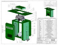
<strong>MTR</strong>-<strong>40F</strong>— CRANKCASE AND ENGINE ASSY.CRANKCASE AND ENGINE ASSY.PAGE 28 — <strong>MTR</strong>-<strong>40F</strong>— PARTS & OPERATION MANUAL — <strong>REV</strong>. #0 (01/21/04)
CRANKCASE & ENGINE ASSY.<strong>MTR</strong>-<strong>40F</strong>— CRANKCASE AND ENGINE ASSY.NO PART NO PART NAME QTY. REMARKSCLUTCH GUIDE / A 1 305117260 CRANK CASE 145 2 305343780 0053204201 CRANK WOODRUFF GEAR KEY 146 3 041006305 301010210BEARING LOCK 6305Z WASHER CLUTCH 14 041006203 BEARING 6203Z 1475 952401450956300130WASHERTHROTTLE8.5 x 22 x 3LEVER AY 25 16 001220825 BOLT 8 x 25 T 17 030208200 WASHER, LOCK M8 19 362455660 BEARING COVER 110 002210620 BOLT 6X20 H,SW 211 050100350 O-RING G-35 113 305333090 CONNECTING ROD 114 042006304 BEARING 6304ZZ 115 080100520 STOP RING R-52 116 952400130 WASHER 9304 117 001220825 BOLT 8 x 25 T 118 030208200 WASHER, LOCK M8 120 303010084 PINION 121 042006007 BEARING 6007ZZ 222 351437750 SPACER 35.4-42.7-11 123 080200350 STOP RING S-35 124 351421900 SPACER, CLUTCH DRUM 125 060504010 OIL SEAL VB-40525 126 050300900 O-RING S-90 127 362454441 CLUTCH ASSY. CE120P 1.6T ........................... 1 ........... INCLUDES ITEMS W/27-1 943020020 CLUTCH SHOE C812 4*27-2 943050050 CLUTCH BOSS C812 127-3 943060100 CLUTCH GUIDE (A) 127-4 943060020 CLUTCH GUIDE (B) 127-5 943030021 CLUTCH SPRING 228*0053204201 WOODRUFF KEY 129 301010210 LOCK WASHER, CLUTCH 130* 0173120010 LOCK NUT 132 362341610 PACKING, FRONT COVER 133 002200620 BOLT 6 x 20 H,SW 934 351010050 GREASE FITTING A-MT6X1 135 351010320 GREASE FITTING B-MT6X1 137 2741500123 ADAPTER FLANGE 138 0011408400 BOLT AND WASHER ASSY. 439 0021808000 NUT 440 0032008000 WASHER, LOCK 4<strong>MTR</strong>-<strong>40F</strong>— PARTS & OPERATION MANUAL — <strong>REV</strong>. #0 (01/21/04) — PAGE 29
<strong>MTR</strong>-<strong>40F</strong>— CRANKCASE AND ENGINE ASSY.CRANKCASE & ENGINE ASSY.PAGE 30 — <strong>MTR</strong>-<strong>40F</strong>— PARTS & OPERATION MANUAL — <strong>REV</strong>. #0 (01/21/04)
<strong>MTR</strong>-<strong>40F</strong>— CRANKCASE AND ENGINE ASSY.CRANKCASE & ENGINE ASSY.NO PART NO PART NAME QTY. REMARKS41 0031108000 WASHER 442 0310060020 DOWEL PIN 263 959006120 CLIP (TCP-10509B) 164 362341620 OIL GAUGE PROTECTOR 165 362341630 LINK PROTECTOR 166 002400820 BOLT 8X20 W/FLAT/LOCK WASHER 467 2741600113 STIFFENER 168 0011408250 BOLT AND WASHER 469 0011408300 BOLT AND WASHER ASSY. 271 362116871 AIR CLEANER ASSY. ........................................ 1 ........... INCLUDES ITEMS W/#71-1# 362030011 COVER CP, AIR CLEANER 171-2# 362030020 PACKING, AIR CLEANER 171-3# 362030030 ELEMENT CP, AIR CLEANER 171-4# 362030040 BOLT CP, AIR CLEANER 172 353342400 INTAKE PIPE 173 507010110 CLAMP TC-200 274 050300070 O-RING (7) 175 031108160 WASHER, FLAT M8 181 306010020 FRONT COVER 186 911210905 ENGINE ASSY., EH09D<strong>MTR</strong>-<strong>40F</strong>— PARTS & OPERATION MANUAL — <strong>REV</strong>. #0 (01/21/04) — PAGE 31
<strong>MTR</strong>-<strong>40F</strong> — GUIDE CYLINDER ASSY.GUIDE CYLINDER AND FOOT ASSY.PAGE 32 — <strong>MTR</strong>-<strong>40F</strong>— PARTS & OPERATION MANUAL — <strong>REV</strong>. #0 (01/21/04)
GUIDE CYLINDER & FOOT ASSY.NO PART NO PART NAME QTY. REMARKS1 305446380 PISTON PIN 12 080100120 STOP RING R-12 23 305337980 PISTON ROD,M14 14 305451550 PISTON END,M14 16 305446400 STOPPER, UPPER 17 305446410 CYLINDER CAP 18 305446420 MAIN SPRING 29 305212710 SPRING CYLINDER 111 305112730 GUIDE CYLINDER 112 065105010 DUST SEAL DKI-5367811 113 080510680 STOP RING TH-R-68 114 351010050 GREASE FITTING A-MT6x1 215 305446430 STOPPER 116 001220816 BOLT 8x15 H, SW 418 305446440 GRIP 119 001520815 SOCKET HEAD BOLT 8x15 T 220 305446450 DUST SLEEVE 121 305446460 SLEEVE BAND 122 011208030 BOLT 8x30 123 020308060 NUT M8 125 050100800 O-RING G-80 126 002211025 BOLT 10x25 H, SW 4<strong>MTR</strong>-<strong>40F</strong>— GUIDE CYLINDER ASSY.<strong>MTR</strong>-<strong>40F</strong>— PARTS & OPERATION MANUAL — <strong>REV</strong>. #0 (01/21/04) — PAGE 33
<strong>MTR</strong>-<strong>40F</strong>— TANK AND HANDLE ASSY.TANK & HANDLE ASSY.PAGE 34 — <strong>MTR</strong>-<strong>40F</strong>— PARTS & OPERATION MANUAL — <strong>REV</strong>. #0 (01/21/04)
TANK & HANDLE ASSY.<strong>MTR</strong>-<strong>40F</strong>— TANK AND HANDLE ASSY.NO PART NO PART NAME QTY. REMARKS1 306117960 HANDLE 12 351319900 SHOCK ABSORBER 23A 009110007 SOCKET HEAD BOLT 10x20 T 43B 033121009 TOOTHED LOCKWASHER B M10 44 002211020 BOLT 10x20 H, SW 45 939010210 STOPPER RUBBER EH1002 16 030208200 WASHER, LOCK M8 17 020308060 NUT M8 19# 361910021 TANK CAP CP (ORANGE) 110 305910032 FUEL TANK ASSY. ...................................... 1 ............ INCLUDES ITEMS W/#11 361455740 SUB CAP 117# 351437785 HOLDER, COCK 118# 954406020 PACKING, FUEL TANK 119 954300720 FUEL COCK ASSY./CVL-08 1`20# 954406010 STRAINER (#110) 121 001220830 BOLT 8x30 T 222 030208200 WASHER, LOCK M8 223 022710809 NYLON NUT M8 224 952401450 WASHER 8.5x22x3 231# 954404890 FILTER, TANK 132 954403030 HOSE BAND (8) 433 351436350 FUEL HOSE R-75 234 301419750 FUEL FILTER CP 141# 362116890 F. TANK 2L (GRAY) 143 362910060 THROTTLE LEVER ASSY. .......................... 1 ............ INCLUDES ITEMS W/44 362341550 THROTTLE BODY 1*45 362910090 THROTTLE, GEAR CP. W/ BOLT 147 362455620 SLIDER 148 362455630 THROTTLE LEVER 149 050100450 O-RING G-45 150 050200100 O-RING P-10 151 031110160 WASHER, FLAT M10 352 033910070 CONICAL SPRING WASHER 253 096206006 SOCKET HEAD SCREW 6 x 6 154* 022131008 CAP NUT M10 155 020410060 NUT M10, H=6 156 096208020 SOCKET HEAD SCREW 8 x 20 157 020408050 NUT M8, H=5 258 956100040 THROTTLE WIRE 620-710 159* 001220620 BOLT 6X20 T 260 030206150 WASHER, LOCK 261 022130605 CAP NUT M6 2<strong>MTR</strong>-<strong>40F</strong>— PARTS & OPERATION MANUAL — <strong>REV</strong>. #0 (01/21/04) — PAGE 35
<strong>MTR</strong>-<strong>40F</strong>— FOOT ASSY. (OPTION)FOOT ASSY. (OPTION)PAGE 36 — <strong>MTR</strong>-<strong>40F</strong>— PARTS & OPERATION MANUAL — <strong>REV</strong>. #0 (01/21/04)
FOOT ASSY. (OPTION)<strong>MTR</strong>-<strong>40F</strong>— FOOT ASSY. (OPTION)NO PART NO PART NAME QTY. REMARKS30 305910010 FOOT ASSY. 150B ....................... 1 .......... INCLUDES ITEMS W/*31*305333120 FOOT 150B 132*305333130 METAL SHEET 150B 133*305446470 FOOT COVER 134*015110055 SUNK HEAD BOLT 10x50 H 235*022711012 NYLON NUT M10 236*030210250 WASHER, LOCK M10 237*015112075 SUNK HEAD BOLT 12x60 H 438*022711214 NYLON NUT M12 439*030212300 WASHER, LOCK M12 4<strong>MTR</strong>-<strong>40F</strong>— PARTS & OPERATION MANUAL — <strong>REV</strong>. #0 (01/21/04) — PAGE 37
<strong>MTR</strong>-<strong>40F</strong>— NARROW FOOT ASSY. (OPTION)NARROW FOOT ASSY. (OPTION)PAGE 38 — <strong>MTR</strong>-<strong>40F</strong>— PARTS & OPERATION MANUAL — <strong>REV</strong>. #0 (01/21/04)
NARROW FOOT ASSY. (OPTION)<strong>MTR</strong>-<strong>40F</strong>— NARROW FOOT ASSY. (OPTION)NO PART NO PART NAME QTY. REMARKSA 305910020 FOOT ASSY. 200B........................................ 1 ........... INCLUDESITEMS W/*A 305910040 FOOT ASSY. 100B........................................ 1 ........... INCLUDES ITEMS W/#1*305333140 FOOT 200B ................................................... 1 ........... 200B1# 305334930 FOOT 100B ................................................... 1 ........... 100B2*305333150 METAL SHEET 200B .................................... 1 ........... 200B2# 305334940 METAL SHEET 100B .................................... 1 ........... 100B3*305446470 FOOT COVER ............................................... 1 ........... 200B3# 305447810 FOOT COVER 96B ....................................... 1 ........... 100B4 # 001611050 SUNK HEAD BOLT 10x50 H 25 # 022711012 NYLON NUT M10 26 # 030210250 WASHER, LOCKM10 27 # 001611252 SUNK HEAD BOLT 12x60 H 48 # 022711214 NYLON NUT M12 49 # 030212300 WASHER, LOCK M10 4*<strong>MTR</strong>-<strong>40F</strong>— PARTS & OPERATION MANUAL — <strong>REV</strong>. #0 (01/21/04) — PAGE 39
<strong>MTR</strong>-<strong>40F</strong>— TRENCH SHOE ASSY. (OPTION)TRENCH SHOE ASSY.PAGE 40 — <strong>MTR</strong>-<strong>40F</strong>— PARTS & OPERATION MANUAL — <strong>REV</strong>. #0 (01/21/04)
TRENCH SHOE ASSY.<strong>MTR</strong>-<strong>40F</strong>— TRENCH SHOE ASSY. (OPTION)NO PART NO PART NAME QTY. REMARKS11 305333160 TRENCH SHOE 500H-120B 111 305333170 TRENCH SHOE 800H-120B 111 305334390 TRENCH SHOE 305H-100B 112 001221235 BOLT 12x35 T 413 020312100 NUT M12 414 030212300 WASHER, LOCK M12 4<strong>MTR</strong>-<strong>40F</strong>— PARTS & OPERATION MANUAL — <strong>REV</strong>. #0 (01/21/04) — PAGE 41
ROBIN EH-09 ENGINE — CRANKCASE ASSY.CRANKCASE ASSY.PAGE 42 — <strong>MTR</strong>-<strong>40F</strong>— PARTS & OPERATION MANUAL — <strong>REV</strong>. #0 (01/21/04)
CRANKCASE ASSY.ROBIN EH-09 ENGINE — CRANKCASE ASSY.NO PART NO PART NAME QTY. REMARKS10 2741010121 CRANKCASE CP ....................................1 ..........INCLUDES ITEMS W/#20% 2371420203 VALVE GUIDE 22630#23716008010440200070STEM SEAL CPOIL SEAL 20X32X61140# 0600200140 BALL BEARING 150#60%03100600200013906600DOWEL PINSTUD2161% 0105060200 STUD 162%70%01050601700105060160STUDSTUD2275# 0440060010 OIL SEAL 6X10X2.5 1809004011400300211140020PLUGGASKET11150 2741600113 STIFFENER 1160 0011408250 BOLT & WASHER 2210 2741100131 MAIN BEARING COVER .........................1 ..........INCLUDES ITEMS W/220 0440200110 OIL SEAL 20X32X6 1*230 0600200140 BALL BEARING 1250* 2304500301 GOVERNOR GEAR CP 1260 2054190103 GOVERNOR SLEAVE 126527000139085002306360113STUDOIL GAUGE41280 0213160020 GASKET 130061001300602002741300131BOLT & WASHER 9CYLINDER HEAD CP .............................1 ..........INCLUDES ITEMS W/%620 2741550103 GASKET, HEAD 163068001100802102741550223FLANGE BOLTROCKER COVER41690 2741600403 GASKET (ROCKET COVER) 170071003100600200011406600DOWEL PINBOLT & WASHER ASSY.24727 0566000250 CLAMP 182082127414401012741620103BREATHER PLATE CPGASKET/BREATHER PLATE11825 2741440503 OIL SHELTER PLATE 1850850-127416102030566000331BREATHER PIPECLAMP, BREATHER, PIPE11852 0569000010 HOSE CLIP 186096000113051002749900107BOLT & WASHER ASSY.GASKET SET21<strong>MTR</strong>-<strong>40F</strong>— PARTS & OPERATION MANUAL — <strong>REV</strong>. #0 (01/21/04) — PAGE 43
CRANKSHAFT AND PISTON ASSY.ROBIN EH-09 ENGINE — CRANKSHAFT AND PISTON ASSY.PAGE 44 — <strong>MTR</strong>-<strong>40F</strong>— PARTS & OPERATION MANUAL — <strong>REV</strong>. #0 (01/21/04)
CRANKSHAFT AND PISTON ASSY.ROBIN EH-09 ENGINE — CRANKSHAFT AND PISTON ASSY.NO PART NO PART NAME QTY. REMARKS104027420101410230200100CRANKSHAFT CPSPACER T=0.81140 0230200110 SPACER T=1.0 1405002302001200021812000SPACER T=1.2NUT1160 0032012000 SPRING WASHER .................................. 1 ..........REPLACES 0032012000707500532031010053204201WOODRUFF KEYWOODRUFF KEY11170 0173120010 LOCK NUT 1310320%23022501202302300123CONNECTING ROD ASSY. ....................1 ..........INCLUDES ITEMS W/%CONNECTING ROD BOLT 2350 2302330103 PISTON PIN 136036027423401032742340203PISTONPISTON 0.25MM11360 2742340303 PISTON 0.50MM 137037027423501072742350207PISTON RING SETPISTON RING SET 0.25MM11370 2742350307 PISTON RING SET 0.50MM 1380 0565110010 CLIP 2<strong>MTR</strong>-<strong>40F</strong>— PARTS & OPERATION MANUAL — <strong>REV</strong>. #0 (01/21/04) — PAGE 45
INTAKE AND EXHAUST ASSY.ROBIN EH-09 ENGINE —INTAKE AND EXHAUST ASSY.PAGE 46 — <strong>MTR</strong>-<strong>40F</strong>— PARTS & OPERATION MANUAL — <strong>REV</strong>. #0 (01/21/04)
INTAKE AND EXHAUST ASSY.ROBIN EH-09 ENGINE —INTAKE AND EXHAUST ASSY.NO PART NO PART NAME QTY. REMARKS103427431701012273860123CAMSHAFT CP ............................ 1 ........INCLUDES ITEMS W/%PIN (SPRING) 135% 2743640103 RELEASE LEVER 136%37%00519041000031517000SPRING PINSNAP RING1138 2743870103 RETURN SPRING 1506027433301032743360103TAPPETVALVE SPRING2270 2743370103 SPRING RETAINER 2809027433401032743350103INTAKE VALVEEXHAUST VALVE1195 13210KA031 COLLET VALVE 421022027435301032743600103PUSH RODROCKER ARM22230 2693580103 BOLT (PIVOT) 224026001700600902743650103NUTGUIDE PLATE21310 2743010211 MUFFLER CP 133034027437001112743520101BRACKET CP (MUFFLER)GASKET CP (EXHAUST)11350 0176060020 SELF LOCK NUT 235136000238060000110060010FLANGE NUT ............................... 2 ........REPLACES 0023806000BOLT AND WASHER ASSY. ........ 2 ........REPLACES 0011406120375 0011306120 FLANGE BOLT ............................. 2 ........REPLACES 0110060010510 2743260400 AIR CLEANER ASSY. ................... 1 ........INCLUDES ITEMS W/511 % 2303262008 GASKET 1*520 2743260307 ELEMENT SET 1540* 2303290103 INSULATOR 1550 2303590103 GASKET (INSULATOR) 156057023035902030176060020GASKET 2 (INSULAT0R)SELF LOCK NUT22<strong>MTR</strong>-<strong>40F</strong>— PARTS & OPERATION MANUAL — <strong>REV</strong>. #0 (01/21/04) — PAGE 47
ROBIN EH-09 ENGINE —GOVERNOR ASSY.GOVERNOR ASSY.PAGE 48 — <strong>MTR</strong>-<strong>40F</strong>— PARTS & OPERATION MANUAL — <strong>REV</strong>. #0 (01/21/04)
GOVERNOR ASSY.ROBIN EH-09 ENGINE —GOVERNOR ASSY.NO PART NO PART NAME QTY. REMARKS102027442301012304220103GOVERNOR LEVERGOVERNOR SHAFT1130 2744270113 GOVERNOR ROD 1405010642801130031305000ROD SPRINGCLIP1260 0011406250 BOLT AND WASHER ASSY. 1708001860600202744250103NUTGOVERNOR SPRING11200 2304330210 SPEED CONTROL ASSY. 121023000431041400140040070SCREW (PAN HEAD)SCREW11235 2684500103 CONTROL SPRING 128034522643103010217100020LINK PIVOT CPFRICTION WASHER11360 0043106300 SCREW 137038500227060002744510101NUT ......................................................... 1 ....... REPLACES 0022706000BASE PLATE CP 1386 0110060050 FLANGE BOLT ....................................... 2 ....... REPLACES 011006001048048622645003130230100040RETURN SPRINGSPACER11<strong>MTR</strong>-<strong>40F</strong>— PARTS & OPERATION MANUAL — <strong>REV</strong>. #0 (01/21/04) — PAGE 49
ROBIN EH-09 ENGINE —BLOWER HOUSING & RECOIL STARTER ASSY.BLOWER HOUSING & RECOIL STARTER ASSY.PAGE 50 — <strong>MTR</strong>-<strong>40F</strong>— PARTS & OPERATION MANUAL — <strong>REV</strong>. #0 (01/21/04)
ROBIN EH-09 ENGINE —BLOWER HOUSING & RECOIL STARTER ASSY.BLOWER HOUSING & RECOIL STARTER ASSY.NO PART NO PART NAME QTY. REMARKS101127451202112745510121BLOWER HOUSING CPBLOWER H. BKT. 1 CP1112 2745520101 BLOWER H. BKT. 2 CP 11314011006002000116061<strong>40F</strong>LANGE BOLTBOLT AND WASHER ASSY.2215 2745500101 BLOWER GUIDE CP 1162001100600502749170103FLANGE BOLT ....................................... 1 ....... REPLACES 0110060010LABEL (TRADE MARK) 140 0110060050 FLANGE BOLT ....................................... 1 ....... REPLACES 0110060010414601100600200110060020FLANGE BOLTFLANGE BOLT1260 2745260103 CYLINDER BAFFLE 1210 2745020120 RECOIL STARTER ASSY. ...................... 1 ....... INCLUDES ITEM W/210-1 2745011508 SPIRAL SPRING 1*210-2 2745012018 REEL 1210-3 2745011108 STARTER ROPE 1210-4 2615010008 STARTER KNOB 1210-5 2705012508 RATCHET 2210-6 2275013108 FRICTION SPRING 1210-11*2745014508 STARTING PULLEY 1210-24 1315015008 SLIDE PLATE 1210-35 2705026108 RATCHET GUIDE 1210-49 2275015208 SET SCREW 1216*2069170103 LABEL (TRADE MARK) 1220 0110060020 FLANGE BOLT 3<strong>MTR</strong>-<strong>40F</strong>— PARTS & OPERATION MANUAL — <strong>REV</strong>. #0 (01/21/04) — PAGE 51
ROBIN EH-09 ENGINE — CARBURETOR ASSY.CARBURETOR ASSY.PAGE 52 — <strong>MTR</strong>-<strong>40F</strong>— PARTS & OPERATION MANUAL — <strong>REV</strong>. #0 (01/21/04)
CARBURETOR ASSY.ROBIN EH-09 ENGINE — CARBURETOR ASSY.ROBIN EH-09 ENGINE — CARBURETOR ASSY.NO PART NO PART NAME QTY. REMARKS210 2746230100 CARBURETOR ASSY. ......................... 1 .......... INCLUDES ITEMS W/-1 2746253508 THROTTLE VALVE 1*-3 2306252508 CHOKE VALVE 1-4 2376245108 SCREW 3-5 2346242108 PILOT JET 1-8 2746252008 SHAFT ASSY. (CHOKE) 1-11 2746253008 SHAFT ASSY. (THROTTLE) 1-12 2246254308 BOLT 1-14 2268250208 NEEDLE VALVE ASSY. 1-15 2146251508 PIN 1-16 2306255308 FLOAT CHAMBER BODY 1-17 2078234508 INSERT WASHER 1-18 2306254008 PACKING 1-19 2306250608 FLOAT ASSY. 1-22 2746240008 MAIN JET 1-24 2266270118 CLIP 1-26 2746235108 HOSE 1-28 2246245008 SCREW 1-29 2106231808 SPRING 1-33 2306258108 SEAL 1-40 1066239308 SCREW 1-41 2066244608 SPRING 1-101 2306258208 PACKING 1-117 2746235008 HOSE 1-123 2276240408 MAIN JET 1*<strong>MTR</strong>-<strong>40F</strong>— PARTS & OPERATION MANUAL — <strong>REV</strong>. #0 (01/21/04) — PAGE 53
ROBIN EH-09 ENGINE —ELECTRIC DEVICE ASSY.ELECTRIC DEVICE ASSY.PAGE 54 — <strong>MTR</strong>-<strong>40F</strong>— PARTS & OPERATION MANUAL — <strong>REV</strong>. #0 (01/21/04)
ROBIN EH-09 ENGINE — ELECTRIC DEVICE ASSY.ELECTRIC DEVICE ASSY.NO PART NO PART NAME QTY. REMARKS101123070208312747020101FLYWHEEL CPIGNITION COIL CP1130 0011706250 BOLT & WASHER ASSY. 2607006600003610150040090SWITCH ASSY.TAPPING SCREW1275 0566030010 CLAMP 19510006590000100650140470PLUG TERMINALSPARK PLUG NGK11110 2307510113 SPARK PLUG CAP 1<strong>MTR</strong>-<strong>40F</strong>— PARTS & OPERATION MANUAL — <strong>REV</strong>. #0 (01/21/04) — PAGE 55
Effective: October 1, 2002TERMS AND CONDITIONS OF SALE — PARTSPAYMENT TERMSTerms of payment for parts are net 10 days.FREIGHT POLICYAll parts orders will be shipped collect orprepaid with the charges added to the invoice.All shipments are F.O.B. point of origin.Multiquip’s responsibility ceases when asigned manifest has been obtained from thecarrier, and any claim for shortage or damagemust be settled between the consignee and thecarrier.MINIMUM ORDERThe minimum charge for orders from Multiquipis $15.00 net. Customers will be askedfor instructions regarding handling of ordersnot meeting this requirement.RETURNED GOODS POLICYReturn shipments will be accepted and creditwill be allowed, subject to the following provisions:1. A Returned Material Authorization mustbe approved by Multiquip prior to shipment.2. To obtain a Return Material Authorization,a list must be provided to MultiquipParts Sales that defines item numbers,quantities, and descriptions of the itemsto be returned.a. The parts numbers and descriptionsmust match the current parts pricelist.b. The list must be typed or computergenerated.c. The list must state the reason(s) forthe return.d. The list must reference the salesorder(s) or invoice(s) under whichthe items were originally purchased.e. The list must include the name andphone number of the person requestingthe RMA.3. A copy of the Return Material Authorizationmust accompany the return shipment.4. Freight is at the sender’s expense. Allparts must be returned freight prepaid toMultiquip’s designated receiving point.5. Parts must be in new and resalable condition,in the original Multiquip package (ifany), and with Multiquip part numbersclearly marked.6. The following items are not returnable:a. Obsolete parts. (If an item is in theprice book and shows as beingreplaced by another item, it isobsolete.)b. Any parts with a limited shelf life(such as gaskets, seals, “O” rings,and other rubber parts) that werepurchased more than six months priorto the return date.c. Any line item with an extended dealernet price of less than $5.00.d. Special order items.e. Electrical components.f. Paint, chemicals, and lubricants.g. Decals and paper products.h. Items purchased in kits.7. The sender will be notified of anymaterial received that is not acceptable.8. Such material will be held for fiveworking days from notification, pendinginstructions. If a reply is not receivedwithin five days, the material will be returnedto the sender at his expense.9. Credit on returned parts will be issued atdealer net price at time of the originalpurchase, less a 15% restocking charge.10. In cases where an item is accepted, forwhich the original purchase documentcan not be determined, the price will bebased on the list price that was effectivetwelve months prior to the RMA date.11. Credit issued will be applied to futurepurchases only.PRICING AND REBATESPrices are subject to change without priornotice. Price changes are effective on a specificdate and all orders received on or after thatdate will be billed at the revised price. Rebatesfor price declines and added charges for priceincreases will not be made for stock on handat the time of any price change.Multiquip reserves the right to quote and selldirect to Government agencies, and to OriginalEquipment Manufacturer accounts whouse our products as integral parts of their ownproducts.SPECIAL EXPEDITING SERVICEA $35.00 surcharge will be added to the invoicefor special handling including bus shipments,insured parcel post or in cases where Multiquipmust personally deliver the parts to the carrier.LIMITATIONS OF SELLER’S LIABILITYMultiquip shall not be liable here under fordamages in excess of the purchase price of theitem with respect to which damages areclaimed, and in no event shall Multiquip beliable for loss of profit or good will or for anyother special, consequential or incidental damages.LIMITATION OF WARRANTIESNo warranties, express or implied, are madein connection with the sale of parts or tradeaccessories nor as to any engine not manufacturedby Multiquip. Such warranties made inconnection with the sale of new, complete unitsare made exclusively by a statement of warrantypackaged with such units, and Multiquipneither assumes nor authorizes any person toassume for it any other obligation or liabilitywhatever in connection with the sale of itsproducts. Apart from such written statement ofwarranty, there are no warranties, express,implied or statutory, which extend beyond thedescription of the products on the face hereof.PAGE 56 — <strong>MTR</strong>-<strong>40F</strong>— PARTS & OPERATION MANUAL — <strong>REV</strong>. #0 (01/21/04)
<strong>MTR</strong>-<strong>40F</strong>— PARTS & OPERATION MANUAL — <strong>REV</strong>. #0 (01/21/04) — PAGE 57NOTE PAGE
OPERATION AND PARTS MANUALHERE'S HOW TO GET HELPPLEASE HAVE THE MODEL AND SERIALNUMBER ON-HAND WHEN CALLINGMULTIQUIP’S MAIN PHONE NUMBERS800-421-1244 FAX: 310-537-3927310-537-3700PARTS DEPARTMENT800-427-1244 FAX: 800-672-7877310-537-3700 FAX: 310-637-3284MAYCO PARTS800-306-2926 FAX: 800-672-7877310-537-3700 FAX: 310-637-3284SERVICE DEPARTMENT800-478-1244 FAX: 310-537-4259310-537-3700MQ POWER SERVICE DEPARTMENT800-835-2551 FAX: 310-638-8046310-537-3700TECHNICAL ASSISTANCE800-478-1244 FAX: 310-631-5032WARRANTY DEPARTMENT800-421-1244, EXT. 279 FAX: 310-537-1173310-537-3700, EXT. 279MULTIQUIP INC.POST OFFICE BOX 6254CARSON, CA 90749310-537-3700 • 800-421-1244FAX: 310-537-3927E-MAIL: mq@multiquip.comWWW: multiquip.comAtlanta • Boise • Dallas • Houston • NewarkQuebec, Canada • Manchester, UK • Rio De Janiero, BR • Guadalajara, MXmanufactured for Multiquip Inc.byMIKASA SANGYO CO., LTD. Tokyo, Japan