8-in x 13-in Horizontal Cut-Off Bandsaw - Southern Tool
8-in x 13-in Horizontal Cut-Off Bandsaw - Southern Tool
8-in x 13-in Horizontal Cut-Off Bandsaw - Southern Tool

You also want an ePaper? Increase the reach of your titles
YUMPU automatically turns print PDFs into web optimized ePapers that Google loves.
This Manual is Bookmarked<br />
This Manual is Bookmarked<br />
Owner's Manual<br />
8-<strong>in</strong> x <strong>13</strong>-<strong>in</strong> <strong>Horizontal</strong> <strong>Cut</strong>-<strong>Off</strong> <strong>Bandsaw</strong><br />
Model: 7015<br />
WMH TOOL GROUP<br />
2420 Vantage Drive<br />
Elg<strong>in</strong>, Ill<strong>in</strong>ois 60123 Part No. M-7015<br />
Ph.: 800-274-6848 Revision A 06/06<br />
www.wmhtoolgroup.com<br />
Copyright © WMH <strong>Tool</strong> Group
Warranty and Service<br />
WMH <strong>Tool</strong> Group, Inc., warrants every product it sells. If one of our tools needs service or repair, one of our<br />
Authorized Service Centers located throughout the United States can give you quick service. In most cases, any of<br />
these WMH <strong>Tool</strong> Group Authorized Service Centers can authorize warranty repair, assist you <strong>in</strong> obta<strong>in</strong><strong>in</strong>g parts, or<br />
perform rout<strong>in</strong>e ma<strong>in</strong>tenance and major repair on your WILTON® tools. For the name of an Authorized Service Center<br />
<strong>in</strong> your area call 1-800-274-6848.<br />
MORE INFORMATION<br />
Group distributor, or visit wiltontool.com.<br />
WARRANTY<br />
WILTON products carry a limited warranty which varies <strong>in</strong> duration based upon the product. (MW = Metalwork<strong>in</strong>g)<br />
WHAT IS COVERED?<br />
This warranty covers any defects <strong>in</strong> workmanship or materials subject to the exceptions stated below. <strong>Cut</strong>t<strong>in</strong>g tools,<br />
abrasives and other consumables are excluded from warranty coverage.<br />
WHO IS COVERED?<br />
This warranty covers only the <strong>in</strong>itial purchaser of the product.<br />
WHAT IS THE PERIOD OF COVERAGE?<br />
The general WILTON warranty lasts for the time period specified <strong>in</strong> the product literature of each product.<br />
WHAT IS NOT COVERED?<br />
This warranty does not cover defects due directly or <strong>in</strong>directly to misuse, abuse, negligence or accidents, normal<br />
wear-and-tear, improper repair or alterations, or lack of ma<strong>in</strong>tenance.<br />
HOW TO GET SERVICE<br />
The product or part must be returned for exam<strong>in</strong>ation, postage prepaid, to a location designated by us. For the name<br />
of the location nearest you, please call 1-800-274-6848.<br />
You must provide proof of <strong>in</strong>itial purchase date and an explanation of the compla<strong>in</strong>t must accompany the<br />
merchandise. If our <strong>in</strong>spection discloses a defect, we will repair or replace the product, or refund the purchase price,<br />
at our option.<br />
We will return the repaired product or replacement at our expense unless it is determ<strong>in</strong>ed by us that there is no<br />
defect, or that the defect resulted from causes not with<strong>in</strong> the scope of our warranty <strong>in</strong> which case we will, at your<br />
direction, dispose of or return the product. In the event you choose to have the product returned, you will be<br />
responsible for the handl<strong>in</strong>g and shipp<strong>in</strong>g costs of the return.<br />
HOW STATE LAW APPLIES<br />
This warranty gives you specific legal rights; you may also have other rights which vary from state to state.<br />
LIMITATIONS ON THIS WARRANTY<br />
WMH TOOL GROUP LIMITS ALL IMPLIED WARRANTIES TO THE PERIOD OF THE LIMITED WARRANTY FOR<br />
EACH PRODUCT. EXCEPT AS STATED HEREIN, ANY IMPLIED WARRANTIES OR MERCHANTABILITY AND<br />
FITNESS ARE EXCLUDED. SOME STATES DO NOT ALLOW LIMITATIONS ON HOW LONG THE IMPLIED<br />
WARRANTY LASTS, SO THE ABOVE LIMITATION MAY NOT APPLY TO YOU.<br />
WMH TOOL GROUP SHALL IN NO EVENT BE LIABLE FOR DEATH, INJURIES TO PERSONS OR PROPERTY,<br />
OR FOR INCIDENTAL, CONTINGENT, SPECIAL, OR CONSEQUENTIAL DAMAGES ARISING FROM THE USE<br />
OF OUR PRODUCTS. SOME STATES DO NOT ALLOW THE EXCLUSION OR LIMITATION OF INCIDENTAL OR<br />
CONSEQUENTIAL DAMAGES, SO THE ABOVE LIMITATION OR EXCLUSION MAY NOT APPLY TO YOU.<br />
WMH <strong>Tool</strong> Group sells through distributors only. The specifications <strong>in</strong> WMH catalogs are given as general <strong>in</strong>formation and are not<br />
b<strong>in</strong>d<strong>in</strong>g. Members of WMH <strong>Tool</strong> Group reserve the right to effect at any time, without prior notice, those alterations to parts, fitt<strong>in</strong>gs,<br />
and accessory equipment which they may deem necessary for any reason whatsoever.<br />
2
Table of Contents<br />
Warranty and Service....................................................................................................................................2<br />
Table of Contents..........................................................................................................................................3<br />
Warn<strong>in</strong>gs .......................................................................................................................................................4<br />
Introduction ...................................................................................................................................................6<br />
Specifications ................................................................................................................................................6<br />
Mach<strong>in</strong>e Features .........................................................................................................................................7<br />
Unpack<strong>in</strong>g and Assembly..............................................................................................................................8<br />
Electrical Connection ....................................................................................................................................8<br />
Controls and Indicators .................................................................................................................................9<br />
Blade Selection ...........................................................................................................................................10<br />
Operations...................................................................................................................................................10<br />
Adjustments ................................................................................................................................................14<br />
Ma<strong>in</strong>tenance................................................................................................................................................18<br />
Clean<strong>in</strong>g ......................................................................................................................................................20<br />
Lubrication...................................................................................................................................................20<br />
Coolant........................................................................................................................................................20<br />
Troubleshoot<strong>in</strong>g ..........................................................................................................................................21<br />
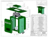
Parts............................................................................................................................................................23<br />
Parts List – 7015 Saw Stand and Bed.....................................................................................................23<br />
Parts Breakdown – 7015 Saw Stand and Bed ........................................................................................25<br />
Parts List – 7015 Saw Head....................................................................................................................26<br />
Parts Breakdown – Model 7015 Saw Head.............................................................................................29<br />
Parts List and Breakdown – 7015 Electric Assembly..............................................................................30<br />
Wir<strong>in</strong>g Diagram ...........................................................................................................................................31<br />
Order<strong>in</strong>g Replacement Parts.......................................................................................................................32<br />
The specifications <strong>in</strong> this manual are given as general <strong>in</strong>formation and are not b<strong>in</strong>d<strong>in</strong>g. WMH <strong>Tool</strong> Group<br />
reserves the right to effect, at any time and without prior notice, changes or alterations to parts, fitt<strong>in</strong>gs,<br />
and accessory equipment deemed necessary for any reason whatsoever.<br />
3
Warn<strong>in</strong>gs<br />
1. Read and understand the entire owner's manual before attempt<strong>in</strong>g assembly or operation.<br />
2. Read and understand the warn<strong>in</strong>gs posted on the mach<strong>in</strong>e and <strong>in</strong> this manual. Failure to comply with<br />
all of these warn<strong>in</strong>gs may cause serious <strong>in</strong>jury.<br />
3. Replace the warn<strong>in</strong>g labels if they become obscured or removed.<br />
4. The bandsaw is designed and <strong>in</strong>tended for use by properly tra<strong>in</strong>ed and experienced personnel only. If<br />
you are not familiar with the proper and safe operation of a bandsaw, do not use until proper tra<strong>in</strong><strong>in</strong>g<br />
and knowledge have been obta<strong>in</strong>ed.<br />
5. Do not use this bandsaw for other than its <strong>in</strong>tended use. If used for other purposes, WMH <strong>Tool</strong> Group<br />
disclaims any real or implied warranty and holds itself harmless from any <strong>in</strong>jury that may result from<br />
that use.<br />
6. Always wear approved safety glasses/face shields while us<strong>in</strong>g this bandsaw. Everyday eyeglasses<br />
only have impact resistant lenses; they are not safety glasses.<br />
7. Before operat<strong>in</strong>g the bandsaw, remove tie, r<strong>in</strong>gs, watches and other jewelry, and roll sleeves up past<br />
the elbows. Remove all loose cloth<strong>in</strong>g and conf<strong>in</strong>e long hair. Non-slip footwear or anti-skid floor strips<br />
are recommended. Do not wear gloves.<br />
8. Wear ear protectors (plugs or muffs) dur<strong>in</strong>g extended periods of operation.<br />
9. Some dust created by power sand<strong>in</strong>g, saw<strong>in</strong>g, gr<strong>in</strong>d<strong>in</strong>g, drill<strong>in</strong>g and other construction activities<br />
conta<strong>in</strong> chemicals known to cause cancer, birth defects or other reproductive harm. Some examples<br />
of these chemicals are:<br />
• Lead from lead based pa<strong>in</strong>t.<br />
• Crystall<strong>in</strong>e silica from bricks, cement and other masonry products.<br />
• Arsenic and chromium from chemically treated lumber.<br />
10. Your risk of exposure varies, depend<strong>in</strong>g on how often you do this type of work. To reduce your<br />
exposure to these chemicals, work <strong>in</strong> a well-ventilated area and work with approved safety<br />
equipment, such as face or dust masks that are specifically designed to filter out microscopic<br />
particles.<br />
11. Do not operate this mach<strong>in</strong>e while tired or under the <strong>in</strong>fluence of drugs, alcohol or any medication.<br />
12. Make certa<strong>in</strong> the switch is <strong>in</strong> the OFF position before connect<strong>in</strong>g the mach<strong>in</strong>e to the power supply.<br />
<strong>13</strong>. Make certa<strong>in</strong> the mach<strong>in</strong>e is properly grounded.<br />
14. Make all mach<strong>in</strong>e adjustments or ma<strong>in</strong>tenance with the mach<strong>in</strong>e unplugged from the power source.<br />
15. Remove adjust<strong>in</strong>g keys and wrenches. Form a habit of check<strong>in</strong>g to see that keys and adjust<strong>in</strong>g<br />
wrenches are removed from the mach<strong>in</strong>e before turn<strong>in</strong>g it on.<br />
16. Keep safety guards <strong>in</strong> place at all times when the mach<strong>in</strong>e is <strong>in</strong> use. If removed for ma<strong>in</strong>tenance<br />
purposes, use extreme caution and replace the guards immediately.<br />
17. Make sure the bandsaw is firmly placed on a secure foundation.<br />
18. Check damaged parts. Before further use of the mach<strong>in</strong>e, a guard or other part that is damaged<br />
should be carefully checked to determ<strong>in</strong>e that it will operate properly and perform its <strong>in</strong>tended<br />
function. Check for alignment of mov<strong>in</strong>g parts, b<strong>in</strong>d<strong>in</strong>g of mov<strong>in</strong>g parts, breakage of parts, mount<strong>in</strong>g<br />
and any other conditions that may affect its operation. A guard or other part that is damaged should<br />
be properly repaired or replaced.<br />
19. Provide for adequate space surround<strong>in</strong>g work area and non-glare, overhead light<strong>in</strong>g.<br />
20. Keep the floor around the mach<strong>in</strong>e clean and free of scrap material, oil and grease.<br />
4
21. Keep visitors a safe distance from the work area. Keep children away.<br />
22. Make your workshop child proof with padlocks, master switches or by remov<strong>in</strong>g starter keys.<br />
23. Give your work undivided attention. Look<strong>in</strong>g around, carry<strong>in</strong>g on a conversation and “horse-play” are<br />
careless acts that can result <strong>in</strong> serious <strong>in</strong>jury.<br />
24. Ma<strong>in</strong>ta<strong>in</strong> a balanced stance at all times so that you do not fall <strong>in</strong>to the blade or other mov<strong>in</strong>g parts. Do<br />
not overreach or use excessive force to perform any mach<strong>in</strong>e operation.<br />
25. Use the right tool at the correct speed and feed rate. Do not force a tool or attachment to do a job for<br />
which it was not designed. The right tool will do the job better and safer.<br />
26. Use recommended accessories; improper accessories may be hazardous.<br />
27. Ma<strong>in</strong>ta<strong>in</strong> tools with care. Keep saw blades sharp and clean for the best and safest performance.<br />
Follow <strong>in</strong>structions for lubricat<strong>in</strong>g and chang<strong>in</strong>g accessories.<br />
28. Turn off the mach<strong>in</strong>e before clean<strong>in</strong>g. Use a brush or compressed air to remove chips or debris — do<br />
not use your hands.<br />
29. Do not stand on the mach<strong>in</strong>e. Serious <strong>in</strong>jury could occur if the mach<strong>in</strong>e tips over.<br />
30. Never leave the mach<strong>in</strong>e runn<strong>in</strong>g unattended. Turn the power off and do not leave the mach<strong>in</strong>e until it<br />
comes to a complete stop.<br />
31. Remove loose items and unnecessary work pieces from the area before start<strong>in</strong>g the mach<strong>in</strong>e.<br />
32. Always wear leather gloves when handl<strong>in</strong>g saw blade. The operator shall not wear gloves when<br />
operat<strong>in</strong>g the mach<strong>in</strong>e.<br />
33. All doors shall be closed, all panels replaced, and other safety guards <strong>in</strong> place prior to the mach<strong>in</strong>e<br />
be<strong>in</strong>g started or operated.<br />
34. Be sure that the blade is not <strong>in</strong> contact with the workpiece when the motor is started. The motor shall<br />
be started and you should allow the saw to come up to full speed before br<strong>in</strong>g<strong>in</strong>g the saw blade <strong>in</strong>to<br />
contact with the workpiece.<br />
35. Keep hands away from the blade area. See Figure A.<br />
36. Remove any cut off piece carefully while keep<strong>in</strong>g your hands free of the blade area.<br />
37. Saw must be stopped and electrical supply must be cut off before any blade replacement or<br />
adjustment of blade support mechanism is done, or before any attempt is made to change the drive<br />
belts or before any periodic service or ma<strong>in</strong>tenance is performed on the saw.<br />
38. Remove loose items and unnecessary workpieces from area before start<strong>in</strong>g mach<strong>in</strong>e.<br />
39. Br<strong>in</strong>g adjustable saw guides and guards as close as possible to the workpiece.<br />
40. Always wear protective eye wear when operat<strong>in</strong>g, servic<strong>in</strong>g, or adjust<strong>in</strong>g mach<strong>in</strong>ery. Eyewear shall be<br />
impact resistant, protective safety glasses with side shields comply<strong>in</strong>g with ANSI Z87.1 specifications.<br />
Use of eye wear which does not comply with ANSI Z87.1 specifications could result <strong>in</strong> severe <strong>in</strong>jury<br />
from breakage of eye protection. See Figure B.<br />
41. Nonslip footwear and safety shoes are recommended. See Figure C.<br />
42. The workpiece, or part be<strong>in</strong>g sawed, must be securely clamped before the saw blade enters the<br />
workpiece.<br />
43. Saw must be stopped and electrical supply cut off or mach<strong>in</strong>e unplugged before reach<strong>in</strong>g <strong>in</strong>to cutt<strong>in</strong>g<br />
area.<br />
44. Avoid contact with coolant, especially guard<strong>in</strong>g your eyes.<br />
5
Familiarize yourself with the follow<strong>in</strong>g safety notices used <strong>in</strong> this manual:<br />
This means that if precautions are not heeded, it may result <strong>in</strong> m<strong>in</strong>or <strong>in</strong>jury and/or<br />
possible mach<strong>in</strong>e damage.<br />
even death.<br />
This means that if precautions are not heeded, it may result <strong>in</strong> serious <strong>in</strong>jury or possibly<br />
Introduction<br />
The Wilton Model 7015 <strong>Horizontal</strong> <strong>Cut</strong>-off <strong>Bandsaw</strong> is designed for high production cut-off work. Four<br />
cutt<strong>in</strong>g speeds and a hydraulic feed control allow the efficient cutt<strong>in</strong>g of virtually any material.<br />
The Model 7015 <strong>Horizontal</strong> <strong>Cut</strong>-off <strong>Bandsaw</strong> is equipped with a coolant system that can greatly extend<br />
blade life and speed the cutt<strong>in</strong>g of a variety of materials that are best cut with cutt<strong>in</strong>g fluids and coolants.<br />
Specifications<br />
Model Number ........................................................................................................................................ 7015<br />
Capacity<br />
Rectangular Stock .............................................................................................................8 x 12.9 Inches<br />
Round Stock.............................................................................................................................. 8.9 Inches<br />
Flat Stock ..............................................................................................................................8 x 10 Inches<br />
At 45 Degrees .........................................................................................................................8 x 8 Inches<br />
Speeds ....................................................................................................................... 82, <strong>13</strong>2, 170, 235 FPM<br />
Motor ................................................... 1 1/2 Horsepower, Capacitor Start, 1725 RPM, 1 Phase, 115 /220V<br />
Blade Size ................................................................................................................1 x 0.035 x 1<strong>13</strong>.5 <strong>in</strong>ches<br />
Blade Guides..................................................................Tungsten carbide tip & ball bear<strong>in</strong>g, eccentric shaft<br />
Material.................................................................................................................... Tungsten carbide <strong>in</strong>serts<br />
Sides ............................................................................................................Eccentric shaft, ball bear<strong>in</strong>gs<br />
Blade Wheel......................................................................................................12 <strong>in</strong>ches diameter, cast iron<br />
Dimensions (LWH)<br />
Length .....................................................................................................................................62.5 <strong>in</strong>ches<br />
Width .......................................................................................................................................22.4 <strong>in</strong>ches<br />
Height ............................................................................................................48.4 <strong>in</strong>ches (cutoff position)<br />
Weight ................................................................................................................. Approximately 551 pounds<br />
Vise ........................................................................................................ Rapid act<strong>in</strong>g, screw tighten<strong>in</strong>g vise<br />
Coolant Pump .........................................................................................1/8 Horsepower, 1Phase 115/220V<br />
6
Mach<strong>in</strong>e Features<br />
Figures 1 and 2 depict the ma<strong>in</strong> features of the<br />
Model 7015 <strong>Horizontal</strong> <strong>Cut</strong>-<strong>Off</strong> <strong>Bandsaw</strong>. The<br />
mach<strong>in</strong>e consists of a mach<strong>in</strong>e base onto which<br />
is <strong>in</strong>stalled a saw head.<br />
Saw Head<br />
The saw head (Figure 2) consists of a drive<br />
motor, drive pulleys, gearbox, blade wheels,<br />
blade guides and supports, control panel, blade<br />
tension/blade track<strong>in</strong>g mechanism, wire brush,<br />
and the saw blade.<br />
The drive motor is mounted on a pivot<strong>in</strong>g plate<br />
that sw<strong>in</strong>gs outward to provide V-belt tension.<br />
The motor is fitted with a step pulley; the V-belt<br />
connects to a second step pulley that is<br />
mounted on the <strong>in</strong>put shaft of the gearbox.<br />
A speed-reduc<strong>in</strong>g gearbox is mounted on the<br />
back side of the blade wheel box on the right<br />
side of the mach<strong>in</strong>e. The blade wheel (drive<br />
wheel) is <strong>in</strong>stalled on the output shaft of the<br />
gearbox.<br />
A second blade wheel is located <strong>in</strong> a blade<br />
wheel box on the left of the mach<strong>in</strong>e. The blade<br />
wheel (driven wheel) is mounted on a shaft that<br />
is part of the blade tension/track<strong>in</strong>g mechanism.<br />
The blade tension mechanism is used to tighten<br />
the saw blade on the blade wheels.<br />
Figure 1<br />
Mach<strong>in</strong>e Base<br />
The mach<strong>in</strong>e base consists of a coolant<br />
collection pan mounted on two panels that form<br />
the legs of the mach<strong>in</strong>e. A shelf is provided<br />
under the collection pan that supports a coolant<br />
tank.<br />
The mach<strong>in</strong>e bed mounts on the top of the<br />
collection pan. The bed supports the vise and<br />
the vise-tighten<strong>in</strong>g lead screw.<br />
The coolant tank is equipped with a pump/motor<br />
assembly. The pump/motor circulates coolant<br />
through tub<strong>in</strong>g to cool and lubricate the saw<br />
blade, the blade guides, and the workpiece.<br />
A dra<strong>in</strong>pipe is provided to connect the collection<br />
pan to the coolant tank. A screen is provided <strong>in</strong><br />
the collection pan to screen-out cutt<strong>in</strong>g debris as<br />
the coolant dra<strong>in</strong>s <strong>in</strong>to the coolant tank. Coolant<br />
is added to the tank by pour<strong>in</strong>g coolant <strong>in</strong>to the<br />
collection pan. The tank is easily removed from<br />
its shelf for clean<strong>in</strong>g and ma<strong>in</strong>tenance.<br />
Figure 2<br />
7
The mechanism also has adjustment screws<br />
that enable the saw blade to “track” evenly on<br />
the blade wheels. The adjustment screws<br />
change the angle of the driven blade wheel shaft<br />
so the wheels are aligned. Track<strong>in</strong>g adjustments<br />
are generally made after the saw blade is<br />
changed but may be required periodically due to<br />
wear over time.<br />
An electrical enclosure is attached to the leg<br />
panel on the right side of the mach<strong>in</strong>e. The<br />
enclosure conta<strong>in</strong>s the switches and fuses<br />
required for operation and protection of the drive<br />
motor (Figure 3).<br />
Remove the saw from the shipp<strong>in</strong>g skid; discard<br />
any hold-down devices. Place the saw on the<br />
shop floor; secure the saw to the floor us<strong>in</strong>g<br />
mount<strong>in</strong>g anchors secured through four holes <strong>in</strong><br />
the mach<strong>in</strong>e base. If the saw will be used to cut<br />
long pieces of stock, allow plenty of room for the<br />
length of the stock.<br />
M<strong>in</strong>imal assembly is required (see to Fig. 4),<br />
consist<strong>in</strong>g of mount<strong>in</strong>g the control box, motor,<br />
pulley guard/cover assembly and motor drive<br />
belt. The mount<strong>in</strong>g hardware is already <strong>in</strong> place<br />
on the saw head. Loosen or remove the<br />
hardware, plac<strong>in</strong>g the components (listed above)<br />
<strong>in</strong> place and secure. For the drive belt, refer to<br />
the Drive Belt section on page 19.<br />
Work Stop<br />
Figure 3<br />
A work stop is provided with the mach<strong>in</strong>e to<br />
allow cutt<strong>in</strong>g multiple pieces of identical length<br />
(refer to Figure 12). The stop consists of a rod<br />
onto which is <strong>in</strong>stalled a stop bracket, a tapered<br />
stop, a clamp<strong>in</strong>g knob and a lock<strong>in</strong>g handle. The<br />
rod is <strong>in</strong>stalled <strong>in</strong> a bore <strong>in</strong> the front of the saw<br />
bed. The stop bracket is positioned on the rod<br />
with the tapered stop toward the end of the<br />
workpiece. The bracket is moved <strong>in</strong> or out on the<br />
rod to establish the length of the workpiece.<br />
Control Panel<br />
The control panel is mounted on the top of the<br />
saw head. Refer to the Controls and Indicators<br />
section (page 9) for a description of the controls.<br />
Unpack<strong>in</strong>g and Assembly<br />
Mach<strong>in</strong>e Setup<br />
The cut-off saw has been pre-adjusted at the<br />
factory and several test pieces have been cut to<br />
verify cutt<strong>in</strong>g accuracy.<br />
8<br />
Figure 4<br />
Electrical Connection<br />
Electrical connection must<br />
be made by a licensed electrician. The wir<strong>in</strong>g<br />
methods and practices must comply with<br />
local electrical codes.<br />
The mach<strong>in</strong>e uses high<br />
voltage electrical power that poses a<br />
significant risk of serious <strong>in</strong>jury or death if<br />
proper precautions are not observed<br />
Connect the mach<strong>in</strong>e to the electrical power<br />
branch circuit (refer to the Wir<strong>in</strong>g section on<br />
page 31). Observe the follow<strong>in</strong>g guidel<strong>in</strong>es when<br />
connect<strong>in</strong>g the saw to the power source.<br />
1. Make sure the saw is disconnected from<br />
the electrical power branch circuit (trip the<br />
required circuit breakers or remove the<br />
required fuses).
2. Place a warn<strong>in</strong>g placard or tag on the<br />
service panel to prevent accidental<br />
electrical shock.<br />
3. When <strong>in</strong>stall<strong>in</strong>g the motor power cord <strong>in</strong>to a<br />
receptacle, make sure the plug is<br />
compatible with the receptacle.<br />
4. When us<strong>in</strong>g hard-wired connections,<br />
connect the wires as shown <strong>in</strong> the Wir<strong>in</strong>g<br />
Data section.<br />
5. Install the fuses or reset the breakers.<br />
Check operation of the saw.<br />
4. Loosen the drive motor lock<strong>in</strong>g handle.<br />
Pivot the motor <strong>in</strong>ward to slacken the belt.<br />
5. Select the speed us<strong>in</strong>g the placard on the<br />
cover. Put the V-belt <strong>in</strong> the pulley grooves<br />
of the pulley for the desired speed. Refer to<br />
Figure 6 for belt locations and the speeds<br />
available.<br />
Controls and Indicators<br />
Control Panel<br />
The operat<strong>in</strong>g controls for the cut-off saw are<br />
located on the control panel (Figure 5) and<br />
consist of the follow<strong>in</strong>g controls and <strong>in</strong>dicators:<br />
Coolant Pump Switch – turns the coolant pump<br />
on and off.<br />
Emergency Stop Switch – press to stop the drive<br />
motor. Note: A micro switch also stops the<br />
motor when the workpiece is cut and the saw<br />
head is completely down.<br />
Start Switch – press to start the drive motor. The<br />
saw head must be <strong>in</strong> the raised position.<br />
Power Light – <strong>in</strong>dicates that mach<strong>in</strong>e is plugged<br />
<strong>in</strong> and the outlet circuit breaker is turned on. The<br />
mach<strong>in</strong>e does not need to be runn<strong>in</strong>g for the<br />
power light to be on.<br />
Feed Rate Control – this knob is used to set the<br />
amount of downward force that is applied to the<br />
saw blade. The feed rate is proportional to the<br />
open<strong>in</strong>g of the valve. When set to zero, the saw<br />
head is locked <strong>in</strong> the raised position. Increas<strong>in</strong>g<br />
the valve open<strong>in</strong>g (counterclockwise adjustment)<br />
<strong>in</strong>creases the feed rate; decreas<strong>in</strong>g the valve<br />
open<strong>in</strong>g (clockwise adjustment) reduces the<br />
feed rate.<br />
Blade Speeds<br />
The Model 7015 horizontal cut-off bandsaw has<br />
four blade speeds. The different speeds are<br />
obta<strong>in</strong>ed by chang<strong>in</strong>g the position of the motor<br />
drive V-belt on step pulleys. Change blade<br />
speeds as follows:<br />
1. Disconnect the electrical power from the<br />
cut-off saw branch circuit to prevent<br />
accidental motor start-up<br />
2. Set the saw head at the fully down position.<br />
3. Remove the knob from the drive belt cover.<br />
Sw<strong>in</strong>g cover out and downward to expose<br />
the V-belt and pulleys.<br />
Material to Be <strong>Cut</strong><br />
<strong>Tool</strong> Steel, Sta<strong>in</strong>less<br />
Steel, Alloy Steel,<br />
Phosphor Bronze, Hard<br />
Bonze, Hard Cast Iron,<br />
Malleable Iron<br />
Mild Steel, Soft Cast Iron,<br />
Medium Hard Brass,<br />
Medium Hard Bronze<br />
Soft Brasses and<br />
Bronzes, Hard Alum<strong>in</strong>um,<br />
Plastics<br />
Plastics, Soft and Medium<br />
Alum<strong>in</strong>um, Wood, Other<br />
Light Materials<br />
Figure 5<br />
60Hz<br />
Belt Speed<br />
50Hz<br />
fpm mpm fpm mpm<br />
Belt Position<br />
82 25 68 21 A<br />
<strong>13</strong>2 40 110 33 B<br />
170 51 142 43 C<br />
235 71 196 60 D<br />
Note: Belt position A shown below<br />
Figure 6<br />
6. Pivot the motor outward to tighten the<br />
V-belt. Tighten the lock<strong>in</strong>g handle.<br />
7. Check V-belt tension by push<strong>in</strong>g the V-belt<br />
firmly downward; press down about midway<br />
between the pulleys. When properly tightened,<br />
the V-belt should depress no more<br />
than the width of the belt.<br />
9
Blade Selection<br />
The cut-off saw is delivered with a saw blade<br />
that is adequate for a variety of cut-off jobs on a<br />
variety of common materials. A 10-tooth,<br />
general-purpose blade is provided as standard<br />
equipment with the mach<strong>in</strong>e.<br />
An optional 8-tooth blade and an optional<br />
14-tooth blade are available from Wilton. (Refer<br />
to the Parts section for saw blade part numbers.)<br />
Refer to Figure 5 for the speeds recommended<br />
for various materials. These speeds, while<br />
appropriate for many common shop cutt<strong>in</strong>g<br />
needs, do not encompass the wide variety of<br />
special blade configurations (tooth pitch and set)<br />
and special alloys for cutt<strong>in</strong>g unusual or exotic<br />
materials.<br />
A coarse blade could be used for a solid steel<br />
bar, but a f<strong>in</strong>er tooth blade would be used on a<br />
th<strong>in</strong>-wall steel tube. In general, the blade choice<br />
is determ<strong>in</strong>ed by the thickness of the material;<br />
the th<strong>in</strong>ner the materials; the f<strong>in</strong>er the tooth<br />
pitch.<br />
A m<strong>in</strong>imum of three teeth should be on the<br />
workpiece at all times for proper cutt<strong>in</strong>g. The<br />
blade and workpiece can be damaged if the<br />
teeth are so far apart that they straddle the<br />
workpiece.<br />
For very high production on cutt<strong>in</strong>g of special<br />
materials, or to cut hard-to-cut materials such as<br />
sta<strong>in</strong>less steel, tool steel, or titanium, you can<br />
ask your <strong>in</strong>dustrial distributor for more specific<br />
blade recommendations. The supplier that<br />
provides the workpiece material should be able<br />
to provide you with very specific <strong>in</strong>structions<br />
regard<strong>in</strong>g the best blade (and coolant or cutt<strong>in</strong>g<br />
fluid, if needed) for the material or shape<br />
supplied.<br />
Blade Break-<strong>in</strong> Procedures<br />
New blades are very sharp and, therefore, have<br />
a tooth geometry that is easily damaged if a<br />
careful break-<strong>in</strong> procedure is not followed.<br />
Consult the blade manufacturer’s literature for<br />
break-<strong>in</strong> of specific blades on specific materials.<br />
However, the follow<strong>in</strong>g procedure will be<br />
adequate for break-<strong>in</strong> of Wilton-supplied blades<br />
on lower alloy ferrous materials.<br />
1. Clamp a section of round stock <strong>in</strong> the vise.<br />
The stock should be 2 <strong>in</strong>ches or larger <strong>in</strong><br />
diameter.<br />
2. Operate the saw at low speed. Start the cut<br />
with a very light feed rate.<br />
3. When the saw has completed 1/3 of the cut,<br />
<strong>in</strong>crease the feed rate slightly and allow the<br />
saw to complete the cut.<br />
4. Keep the hydraulic cyl<strong>in</strong>der needle valve <strong>in</strong><br />
the same position and beg<strong>in</strong> a second cut<br />
on the same or similar workpiece.<br />
5. When the blade has completed about 1/3 of<br />
the cut, <strong>in</strong>crease the feed rate.<br />
Watch the chip formation until cutt<strong>in</strong>g is at its<br />
most efficient rate and allow the saw to<br />
complete the cut (refer to Evaluat<strong>in</strong>g Blade<br />
Efficiency on page 10). The blade is now<br />
considered ready for use.<br />
Operations<br />
Hydraulic Feed Control<br />
The weight of the saw head provides the force<br />
needed to cut through the workpiece. The cut-off<br />
saw has a hydraulic cyl<strong>in</strong>der that controls the<br />
feed rate of the saw.<br />
The hydraulic feed control circuit consists of a<br />
s<strong>in</strong>gle act<strong>in</strong>g hydraulic cyl<strong>in</strong>der (Figure 7) and a<br />
feed rate control (Figure 5). The feed control<br />
cyl<strong>in</strong>der resists motion <strong>in</strong> the downward direction<br />
to control the feed rate. The control cyl<strong>in</strong>der<br />
offers no resistance when raised upward.<br />
The feed rate control knob (Figure 5) controls<br />
the rate at which the saw head is lowered. The<br />
control knob (needle valve) controls the rate at<br />
which the hydraulic fluid is released from the<br />
hydraulic cyl<strong>in</strong>der. When the needle valve is<br />
closed, the cyl<strong>in</strong>der is locked. With the needle<br />
valve slightly open, the cyl<strong>in</strong>der permits slow, or<br />
light, downward force. Open<strong>in</strong>g the needle valve<br />
further <strong>in</strong>creases the feed rate and applies more<br />
weight to the saw blade and workpiece.<br />
The needle valve is adjusted until the saw is<br />
operat<strong>in</strong>g efficiently. The efficiency of operation<br />
is usually evaluated by observ<strong>in</strong>g chip formation.<br />
Blade efficiency is further described below.<br />
10<br />
Figure 7
Evaluat<strong>in</strong>g <strong>Cut</strong>t<strong>in</strong>g Efficiency<br />
Is the blade cutt<strong>in</strong>g efficiently? The best way to<br />
determ<strong>in</strong>e this is to observe the chips formed by<br />
the cutt<strong>in</strong>g blade.<br />
If the chip formation is powdery, then the feed is<br />
much too light, or the blade is dull.<br />
If the chips formed are curled, but colored – blue<br />
or straw colored from heat generated dur<strong>in</strong>g the<br />
cut – then the feed rate is too high.<br />
If the chips are slightly curled and are not<br />
colored by heat – the blade is sufficiently sharp<br />
and is cutt<strong>in</strong>g at its most efficient rate.<br />
Work Setup<br />
Referr<strong>in</strong>g to Figure 8:<br />
1. Set the feed rate control knob (C) to zero.<br />
2. With the lift<strong>in</strong>g handle (A) raise the saw<br />
head (B).<br />
3. Turn the vise handwheel (D) counterclockwise<br />
enough to free the moveable vise<br />
jaw (E). Then pull the moveable vise jaw<br />
away from the fixed vise jaw (H).<br />
4. Place the workpiece (F) on the work<br />
table (G).<br />
For long workpieces, provide support at the<br />
other end. If necessary, provide additional<br />
downward clamp<strong>in</strong>g to hold the workpiece<br />
securely on the worktable.<br />
5. Clamp the workpiece (F) <strong>in</strong> the vise by first<br />
push<strong>in</strong>g the moveable vise jaw (E) aga<strong>in</strong>st<br />
the workpiece. Then rotate the vise handwheel<br />
(D) clockwise to secure the workpiece.<br />
Sett<strong>in</strong>g The Vise For Angle <strong>Cut</strong>s<br />
Referr<strong>in</strong>g to Figure 9, the vise can be adjusted<br />
through a 45-degree arc as follows:<br />
1. Loosen the lock handle (E) that secures the<br />
fixed vise jaw (D).<br />
2. Rotate the fixed vise jaw (D) to the desired<br />
angle, sett<strong>in</strong>g it to the scale on the back<br />
edge of the table.<br />
For accurate cuts, use a variable protractor<br />
to set the position of the jaw, align<strong>in</strong>g one<br />
side of the protractor with the blade.<br />
3. Tighten the lock handle (E).<br />
4. Loosen the hex head bolt (A) on the<br />
moveable vise jaw (C).<br />
5. Place the workpiece (B) between the vise<br />
jaws (C, D).<br />
6. Set the moveable vise jaw (C), press<strong>in</strong>g it<br />
aga<strong>in</strong>st the side of the workpiece (B) and<br />
fixed vise jaw (D).<br />
7. Tighten the hex head bolt (A) on the<br />
moveable vise jaw to secure the jaw.<br />
Figure 9<br />
Sett<strong>in</strong>g the Vise for Square <strong>Cut</strong>s<br />
The procedure for sett<strong>in</strong>g the vise for square<br />
cuts is identical to sett<strong>in</strong>g for angle cuts (above)<br />
except that a mach<strong>in</strong>ist’s square is used to set<br />
the angle of the fixed vise jaw (J, Fig. 10). Align<br />
one side of the square with the side of the slot<br />
(G, Fig. 10) <strong>in</strong> the table.<br />
Figure 8<br />
Figure 10<br />
11
Start<strong>in</strong>g the Saw<br />
Important: The efficient operation of the cut-off<br />
saw is dependent upon the condition of the saw<br />
blade. If the performance of the saw beg<strong>in</strong>s to<br />
deteriorate, the first item that you should check<br />
is the blade.<br />
If a new blade does not restore the mach<strong>in</strong>e’s<br />
cutt<strong>in</strong>g accuracy and quality, refer to the<br />
troubleshoot<strong>in</strong>g guide (or the blade manufacturer’s<br />
guide) for conditions to consider and<br />
adjustments that can be made to <strong>in</strong>crease the<br />
life of the blade.<br />
To change the blade, refer to the Chang<strong>in</strong>g<br />
Blades section on page 18.<br />
Never operate the saw<br />
without blade covers <strong>in</strong> place.<br />
Flats/Strips<br />
Channels<br />
Rounds<br />
Knock off sharp edge<br />
here with file<br />
Angles<br />
Make sure the blade is not <strong>in</strong><br />
contact with the workpiece when the motor<br />
is started. Do not drop the saw head on the<br />
workpiece or force the saw through the<br />
workpiece.<br />
To start the saw:<br />
1. Clamp the workpiece <strong>in</strong> the vise. Refer to<br />
Figure 11 for examples of workpieces <strong>in</strong> the<br />
vise.<br />
Be sure the blade is not <strong>in</strong> contact with the<br />
workpiece when the motor is started.<br />
2. Start the motor and allow the saw to come<br />
up to speed.<br />
3. Slowly set the saw down onto the workpiece<br />
and adjust cutt<strong>in</strong>g speed with the feed<br />
control knob (described on page 9).<br />
4. Do not drop the saw head or force the<br />
cut. Let the weight of the saw head provide<br />
the cutt<strong>in</strong>g force.<br />
5. The saw will automatically shut off at the<br />
end of the cut.<br />
Squares/Rectangles<br />
Hexagonals<br />
Figure 11<br />
I-Beams<br />
Knock off sharp edge<br />
here with file<br />
Tees<br />
12
Coolant Flow and Nozzle Position<br />
The coolant pump must be<br />
submerged before operat<strong>in</strong>g to prevent<br />
damage to the pump.<br />
Adjust the coolant flow shut-off valve at the top<br />
of the saw head weldment. The flow should be<br />
no more than the saw blade can draw <strong>in</strong>to the<br />
workpiece by the movement of the blade.<br />
The coolant flow can be stopped <strong>in</strong> two ways:<br />
<br />
by the coolant selector switch (A, Fig. 4) on<br />
the control box (the preferred method)<br />
by clos<strong>in</strong>g the shut-off valve<br />
Note: The coolant pump is self-circulat<strong>in</strong>g when<br />
the shut-off valve is closed.<br />
Sett<strong>in</strong>g the Work Stop<br />
Referr<strong>in</strong>g to Figure 12:<br />
The work stop is an accessory that is <strong>in</strong>cluded<br />
with the Wilton 7015 <strong>Bandsaw</strong>. It is used to set<br />
up the saw for mak<strong>in</strong>g multiple cuts of the same<br />
length.<br />
Do not allow the blade to rest<br />
on the workpiece when the saw is not<br />
cutt<strong>in</strong>g.<br />
Thread the stop rod (A) <strong>in</strong>to the threaded<br />
open<strong>in</strong>g the on the front of the saw bed (B) as<br />
shown.<br />
Set the work stop as follows:<br />
1. Loosen the stop arm (C).<br />
2. Position the stop arm (C) on the stop rod (A)<br />
to obta<strong>in</strong> the desired length of cut on the<br />
workpiece (D).<br />
3. Rotate the stop arm (C) so it contacts the<br />
end of the workpiece (D).<br />
4. Secure the stop arm.<br />
Figure 12<br />
<strong>13</strong>
Adjustments<br />
Blade Track<strong>in</strong>g Adjustment<br />
Refer to Figures <strong>13</strong> and 14.<br />
Blade track<strong>in</strong>g has been set and tested at the<br />
factory. Adjustment is rarely required when the blade<br />
is used properly or if the blade is correctly welded.<br />
If adjustment is needed:<br />
1. Us<strong>in</strong>g the blade tension handwheel (D), make<br />
sure the blade is properly tensioned.<br />
Note: Blade tension<strong>in</strong>g is described <strong>in</strong> the<br />
Chang<strong>in</strong>g Blades section on page 18).<br />
Keep proper tension at all times.<br />
2. Raise the saw head (A) as shown.<br />
3. Open the wheel guards (B).<br />
4. Remove both of the blade-guide bear<strong>in</strong>g bracket<br />
assemblies (C).<br />
5. Loosen three hex lock<strong>in</strong>g screws (E) <strong>in</strong> the head<br />
weldment (G).<br />
While perform<strong>in</strong>g the follow<strong>in</strong>g,<br />
keep the blade from rubb<strong>in</strong>g excessively on the<br />
shoulder of the wheel. Excessive rubb<strong>in</strong>g will<br />
damage the wheel and/or the blade.<br />
6. Start the saw. Turn the adjustment screws (F) to<br />
tilt the idler wheel (Figure 14) until the blade is<br />
touch<strong>in</strong>g the shoulder of the idler wheel.<br />
Note: As a general rule, make the same adjustment<br />
to the two adjustment screws on the right (F). The<br />
s<strong>in</strong>gle adjustment on the left is <strong>in</strong>dependent.<br />
7. Next, turn the adjustment screws (F) so the<br />
blade starts to move away from the shoulder of<br />
the wheel – then immediately turn the<br />
adjustment screws <strong>in</strong> the other direction so the<br />
blade stops – then moves slowly toward the<br />
shoulder.<br />
Keep f<strong>in</strong>gers clear of the blade<br />
and wheel to avoid <strong>in</strong>jury.<br />
8. Turn the adjustment screws (F) to stop the<br />
motion of the blade on the wheel as it gets<br />
closer to the wheel shoulder.<br />
Put a 6-<strong>in</strong>ch length of paper (J, Fig. 14) between<br />
the blade and the wheel as shown (the saw is<br />
still turned on). The paper should not be cut as it<br />
passes between the wheel shoulder and the<br />
blade.<br />
9. Turn the adjustment screws (F) slightly.<br />
Figure <strong>13</strong><br />
Figure 14
Repeat the <strong>in</strong>sertion of the paper between the<br />
wheel shoulder and the blade until the paper is<br />
cut <strong>in</strong> two pieces.<br />
Note: You may have to repeat the check with the<br />
paper several times before the blade and the<br />
shoulder cut the paper <strong>in</strong>to two pieces. Do not hurry<br />
the adjustment. Patience and accuracy here will pay<br />
off with better, more accurate, quieter cutt<strong>in</strong>g and<br />
much longer mach<strong>in</strong>e and blade life.<br />
When the paper is cut:<br />
10. Turn the adjustment screws (F) slightly <strong>in</strong> the<br />
counter-clockwise direction. This assures that<br />
the blade is not touch<strong>in</strong>g the shoulder of the<br />
wheel.<br />
11. Shut off the saw.<br />
12. Tighten the hex lock<strong>in</strong>g screws (E).<br />
<strong>13</strong>. Install the blade-guide bear<strong>in</strong>g bracket<br />
assemblies (C, Fig. <strong>13</strong>).<br />
14. Position the guides so the top bear<strong>in</strong>g just<br />
touches the blade (see Blade Guide Bear<strong>in</strong>g<br />
Adjustment on page 16) .<br />
15. Close the wheel covers (K, Fig. 14).<br />
Blade Guide Adjustment<br />
Referr<strong>in</strong>g to Figure 15:<br />
The 7015 <strong>Bandsaw</strong> has two adjustable blade guide<br />
assemblies, each consist<strong>in</strong>g of the blade guide<br />
support or bracket (B, H)) and blade guide (A).<br />
The position of the blade guides is important <strong>in</strong> order<br />
to make accurate cuts and prolong blade life and is<br />
determ<strong>in</strong>ed by the size of the workpiece. Adjustment<br />
is made as follows:<br />
Left Blade Guide<br />
1. Place the workpiece (G) <strong>in</strong> the vise (F) and<br />
clamp tightly (refer to Work Setup on page 8).<br />
2. Loosen the left lock knob (C) only.<br />
3. Slide the guide support (D) left or right so that it<br />
just clears the piece to be cut (G).<br />
4. Tighten the lock knob (C).<br />
Right Blade Guide<br />
The right blade guide assembly is set at the factory<br />
and rests aga<strong>in</strong>st the stop (E). It normally does not<br />
require adjustment, except to provide clearance for<br />
workpieces to be cut at a great angle. If adjustment<br />
is required, the procedure is the same as for the left<br />
blade guide adjustment.<br />
Figure 15<br />
15
Blade Guide Bear<strong>in</strong>g Adjustment<br />
Referr<strong>in</strong>g to Figure 16:<br />
Guide bear<strong>in</strong>gs and guide <strong>in</strong>serts are located on<br />
either side of the saw blade and provide stability for<br />
the blade when the saw is <strong>in</strong> operation. These<br />
bear<strong>in</strong>gs rotate on an eccentric shaft so the distance<br />
from the blade can be adjusted for optimal<br />
performance.<br />
Blade guides provide blade support.<br />
Guide bear<strong>in</strong>gs and blade guides are <strong>in</strong>itially<br />
adjusted at the factory and should rarely require<br />
adjustment<br />
It is always better to try a new blade when cutt<strong>in</strong>g<br />
performance is poor. If performance rema<strong>in</strong>s poor<br />
after chang<strong>in</strong>g the blade, check the blade guides for<br />
proper spac<strong>in</strong>g. For most efficient operation and<br />
maximum accuracy, clearance between the blade<br />
and the guide bear<strong>in</strong>gs should be 0.001-<strong>in</strong>ch. The<br />
bear<strong>in</strong>gs will still turn freely with this clearance. If the<br />
clearance is <strong>in</strong>correct, the blade may track off the<br />
drive wheel.<br />
Disconnect the cut-off saw from<br />
its electrical power source.<br />
Check the blade to make sure<br />
the welded section is the same thickness as the<br />
rest of the blade. If the blade is thicker at the<br />
weld, the guide bear<strong>in</strong>gs may be damaged.<br />
If required, adjust first one guide bear<strong>in</strong>g and blade<br />
guide assembly then the other as follows:<br />
1. Us<strong>in</strong>g a 3mm hex wrench, loosen two set screws<br />
(A) secur<strong>in</strong>g the eccentric bush<strong>in</strong>gs.<br />
2. Us<strong>in</strong>g a 5mm hex wrench, loosen two socket<br />
head cap screws (D) secur<strong>in</strong>g the carbide blade<br />
guides (E).<br />
3. Position the bear<strong>in</strong>gs (B) by turn<strong>in</strong>g the bush<strong>in</strong>gs<br />
(C) with a flat-head screwdriver. Set the<br />
clearance between the bear<strong>in</strong>gs (B) and blade<br />
(F) at approximately 0.001 <strong>in</strong>ch.<br />
When properly adjusted, the blade should be <strong>in</strong><br />
a vertical position between the bear<strong>in</strong>gs as<br />
shown <strong>in</strong> Figure 17.<br />
4. Tighten the set screws (A).<br />
5. Adjust the blade guides (E) so they support the<br />
blade without p<strong>in</strong>ch<strong>in</strong>g and tighten the socket<br />
head cap screws.<br />
6. When the adjustment is correct, the guide<br />
bear<strong>in</strong>gs should rotate freely with slight pressure<br />
of the f<strong>in</strong>ger (blade stopped).<br />
Outer<br />
Roller<br />
INCORRECT<br />
Saw Blade<br />
Inner<br />
Roller<br />
Figure 16<br />
Figure 17<br />
CORRECT<br />
Drive Belt Tension Adjustment<br />
Saw Blade<br />
Lock<strong>in</strong>g Screw<br />
The V-belt will stretch with use and may<br />
occasionally require tension adjustment. To adjust<br />
see the Chang<strong>in</strong>g Drive Belt section (page 19)<br />
steps 1, 2, 6, and 7.<br />
16
Verify<strong>in</strong>g Adjustment Accuracy<br />
Refer also to Figure 18.<br />
Test cuts can be used to determ<strong>in</strong>e whether or not<br />
you have adjusted the blade accurately. Use 2 <strong>in</strong>ch<br />
round bar stock to perform these test cuts, as<br />
follows:<br />
1. With the bar stock securely clamped <strong>in</strong> the vise,<br />
make a cut through the bar stock.<br />
2. Mark the top of the bar stock.<br />
3. Move the bar stock about 1/4 <strong>in</strong>ch past the<br />
blade so you can beg<strong>in</strong> a second cut.<br />
4. Rotate the bar stock 180 degrees so the mark<br />
you made is now at the bottom of the cut.<br />
5. Make a cut through the bar stock.<br />
6. Use a micrometer to measure the thickness<br />
variation between the top and bottom of the disk<br />
you have cut from the bar stock.<br />
The saw blade can be considered correctly adjusted<br />
when the variation measured is no more than 0.012<br />
<strong>in</strong>ch across the face of the disk. If you do not have a<br />
piece of 2-<strong>in</strong>ch bar stock available for a test cut, use<br />
a larger diameter test workpiece rather than a<br />
smaller one. The maximum thickness variation on<br />
any test piece should be no more than 0.003 <strong>in</strong>ch,<br />
per side, per <strong>in</strong>ch of stock diameter.<br />
1. Clamp vise and mart top of bar stock here<br />
5. Measure<br />
here ...<br />
Rod<br />
6. ... and measure<br />
here<br />
Figure 18<br />
2. <strong>Cut</strong> of a slice of<br />
the bar stock<br />
3. Rotate stock <strong>in</strong> vise<br />
so mark is at bottom<br />
4. <strong>Cut</strong> off a new<br />
slice from the<br />
stock<br />
7. Difference between<br />
measurements at edges<br />
of disc should be less than<br />
0.003 <strong>in</strong>ches per <strong>in</strong>ch per<br />
side of stock diameter<br />
Switch Adjustment<br />
Disconnect the cut-off saw from<br />
its electrical power source.<br />
Referr<strong>in</strong>g to Figure 19:<br />
Loosen the jam nut and set the adjustment screw so<br />
that the limit switch will actuate to the off position<br />
when the saw has cut through the workpiece.<br />
Counterbalance Spr<strong>in</strong>g Tension<br />
Disconnect the cut-off saw from<br />
its electrical power source.<br />
The counterbalance spr<strong>in</strong>g is located on the rear of<br />
the saw table (refer to Figure 20). The counterbalance<br />
spr<strong>in</strong>g is used to adjust the amount of down<br />
force the saw arm puts on the workpiece when the<br />
hydraulic control cyl<strong>in</strong>der is fully open.<br />
If adjustment is needed:<br />
1. Raise the saw arm to its full upright position and<br />
lock it <strong>in</strong> position.<br />
2. Set the spr<strong>in</strong>g tension by adjust<strong>in</strong>g the nut until<br />
1-1/4 to 1-1/2 <strong>in</strong>ches of are exposed on the right<br />
side of the eyebolt mount.<br />
The saw can now be returned to service.<br />
Figure 19<br />
Figure 20<br />
17
Ma<strong>in</strong>tenance<br />
Chang<strong>in</strong>g Blades<br />
Use leather gloves when<br />
chang<strong>in</strong>g the saw blade to protect your<br />
hands from cuts and scratches. Use<br />
protective eye wear that meets ANSI<br />
Specification Z87.1<br />
Disconnect the cut-off saw<br />
from its electrical power source.<br />
Referr<strong>in</strong>g to Figure 21:<br />
1. Raise the saw head (A). Set the feed rate<br />
control knob (B) to zero to lock the hydraulic<br />
cyl<strong>in</strong>der, which will hold the saw head <strong>in</strong><br />
place.<br />
2. Open two h<strong>in</strong>ged blade wheel covers (C).<br />
3. Remove the blade guard (D) and column<br />
blade cover (E).<br />
4. Turn the blade tension handle (F) counterclockwise<br />
until the blade (G) hangs loose.<br />
5. Us<strong>in</strong>g leather gloves to prevent cuts and<br />
scratches, pull the blade (G) off the drive<br />
wheels (H) and out of the blade guides (J).<br />
Figure 21<br />
18<br />
Store the removed blade carefully before<br />
proceed<strong>in</strong>g.<br />
6. Slide the new blade <strong>in</strong>to the blade guides<br />
(J), then loop the blade (G) around the drive<br />
wheels (H) such that the teeth face towards<br />
the back and the smooth side faces towards<br />
the front.<br />
This will permit the vertical side of the teeth<br />
to contact the workpiece first.<br />
7. Push the blade (G) so it is seated aga<strong>in</strong>st<br />
the shoulders of the wheels (H).<br />
When it is seated aga<strong>in</strong>st the shoulder, turn<br />
the blade tension handle (F) clockwise to<br />
<strong>in</strong>crease the tension. Do not over-tension<br />
the blade; tighten it just enough so it does<br />
not slip while cutt<strong>in</strong>g.<br />
8. When the blade is properly tensioned,<br />
reconnect the saw to the electrical power<br />
source.<br />
9. Check and adjust the track<strong>in</strong>g of the blade.<br />
Refer to Blade Track<strong>in</strong>g Adjustment (on<br />
page 14) if necessary.<br />
10. Close the wheel covers (C).<br />
11. Put 2 to 3 drops of oil on the blade.
Chang<strong>in</strong>g the Drive Belt<br />
Referr<strong>in</strong>g to Figures 22 and 23:<br />
Disconnect the cut-off saw from<br />
its electrical power source.<br />
1. Set the arm at the full horizontal position.<br />
2. Open the drive belt cover to expose the V-belt<br />
and pulleys.<br />
3. Loosen the belt tension adjust knob located <strong>in</strong><br />
the rear under the motor (see Figure 23 for knob<br />
direction). Lift the motor upward to loosen the<br />
belt.<br />
4. Remove the worn V-belt.<br />
5. Put the replacement V-belt <strong>in</strong> the pulley position<br />
for the speed you require (refer to the Blade<br />
Speeds section on page 9).<br />
6. Tighten the V-belt by turn<strong>in</strong>g the belt tension<br />
adjust knob (see Figure 23). The belt must be<br />
secure enough so it does not slip when the<br />
mach<strong>in</strong>e is runn<strong>in</strong>g. Do not over tighten. This will<br />
cause premature wear on belt and pulley<br />
bear<strong>in</strong>gs.<br />
7. Re<strong>in</strong>stall drive belt cover and <strong>in</strong>stall knob.<br />
Figure 22<br />
Replac<strong>in</strong>g the Drive Motor<br />
Disconnect the cut-off saw from<br />
its electrical power source.<br />
Referr<strong>in</strong>g to Figure 24:<br />
1. Remove the drive V-belt (see Chang<strong>in</strong>g the<br />
Drive Motor Belt above).<br />
2. Open the motor junction box and disconnect the<br />
power cord wires from their term<strong>in</strong>als.<br />
3. Remove four screws and washers (A) that<br />
secure the motor (B) to the mount<strong>in</strong>g plate (C).<br />
4. Installation of a new motor is a reversal of the<br />
above steps. Also, complete steps 6 through 8 <strong>in</strong><br />
Chang<strong>in</strong>g Blade Speed (page 9) to complete<br />
tension<strong>in</strong>g of the V-belt to the correct tension —<br />
use a straight edge to be certa<strong>in</strong> the motor<br />
pulley is correctly aligned with the speed reducer<br />
pulley.<br />
Figure 23<br />
Figure 24
Clean<strong>in</strong>g<br />
1. Clean off any preservative on mach<strong>in</strong>e<br />
surfaces.<br />
After clean<strong>in</strong>g:<br />
2. Coat mach<strong>in</strong>ed surfaces of the cutoff saw<br />
with a medium consistency mach<strong>in</strong>e oil.<br />
Reapply the oil coat<strong>in</strong>g at least every six<br />
months.<br />
3. Clean up accumulated saw cutt<strong>in</strong>gs after<br />
use. Make sure the lead screw and rapid nut<br />
are kept free from saw cutt<strong>in</strong>gs and other<br />
material that would cause damage.<br />
4. Clean the chip sludge from the coolant tank.<br />
The frequency should be determ<strong>in</strong>ed by how<br />
often the saw is used.<br />
Lubrication<br />
Lubricate the follow<strong>in</strong>g components at the<br />
specified frequencies and us<strong>in</strong>g the lubricants<br />
def<strong>in</strong>ed as follows:<br />
Ball Bear<strong>in</strong>gs – the bear<strong>in</strong>gs are lubricated and<br />
sealed – periodic lubrication is not required.<br />
Blade Guide Bear<strong>in</strong>g – the bear<strong>in</strong>gs are lubricated<br />
and sealed – periodic lubrication is not<br />
required.<br />
Upper Wheel Bush<strong>in</strong>g – six to eight drops of oil<br />
each week.<br />
Pivot Po<strong>in</strong>ts, Shafts, and Bear<strong>in</strong>g areas – six<br />
to eight drops of oil each week.<br />
Coolant<br />
Change coolant on a frequency appropriate to<br />
the type of coolant be<strong>in</strong>g used. Oil based<br />
coolants can sour. Refer to the coolant<br />
supplier’s <strong>in</strong>structions for change frequency.<br />
The general-purpose coolant is a mixture of<br />
water-soluble oil and water. Mix one part of<br />
soluble oil to ten parts of water (one quart of oil<br />
to ten quarts water). The eleven quarts of<br />
coolant is the amount required for the coolant<br />
pump to operate properly.<br />
There are numerous coolants on the market that<br />
are formulated for special applications. Consult<br />
your local distributor for details <strong>in</strong> the event you<br />
have a long range production task, or are<br />
required to cut some of the more exotic<br />
materials.
Troubleshoot<strong>in</strong>g<br />
Fault Probable Cause Suggested remedy<br />
Excessive blade<br />
breakage<br />
1. Material loose <strong>in</strong> vise.<br />
2. Incorrect speed or feed.<br />
3. Teeth too coarse for material.<br />
4. Incorrect blade tension.<br />
5. Saw blade is <strong>in</strong> contact with<br />
workpiece before the saw is started.<br />
6. Blade rubs on the wheel flange.<br />
7. Misaligned guides.<br />
8. Crack<strong>in</strong>g at weld.<br />
1. Clamp work securely.<br />
2. Check Mach<strong>in</strong>ist’s Handbook for<br />
speed/feed appropriate for the<br />
material be<strong>in</strong>g cut.<br />
3. Check Mach<strong>in</strong>ist’s Handbook for<br />
recommended blade type.<br />
4. Adjust blade tension to the po<strong>in</strong>t<br />
where the blade just does not slip<br />
on the wheel.<br />
5. Start the motor before plac<strong>in</strong>g the<br />
saw on the workpiece.<br />
6. Adjust blade track<strong>in</strong>g.<br />
7. Adjust guides.<br />
8. Longer anneal<strong>in</strong>g cycle.<br />
Premature blade<br />
dull<strong>in</strong>g<br />
Bad cuts (crooked)<br />
1. Blade teeth too coarse.<br />
2. Blade speed too high.<br />
3. Inadequate feed pressure.<br />
4. Hard spots <strong>in</strong> workpiece or scale<br />
on/<strong>in</strong> workpiece.<br />
5. Work harden<strong>in</strong>g of material<br />
(especially sta<strong>in</strong>less steel).<br />
6. Insufficient blade tension.<br />
7. Operat<strong>in</strong>g saw without pressure on<br />
workpiece.<br />
1. Workpiece not square with blade.<br />
2. Feed pressure too fast.<br />
3. Guide bear<strong>in</strong>gs not adjusted<br />
properly.<br />
4. Inadequate blade tension.<br />
5. Span between the two blade guides<br />
too wide.<br />
6. Dull blade.<br />
7. Incorrect blade speed.<br />
8. Blade guide assembly is loose.<br />
9. Blade guide bear<strong>in</strong>g assembly<br />
loose.<br />
10. Blade track too far away from wheel<br />
flanges.<br />
11. Guide bear<strong>in</strong>g worn.<br />
1. Use a f<strong>in</strong>er tooth blade.<br />
2. Try a lower blade speed.<br />
3. Decrease spr<strong>in</strong>g tension.<br />
4. Increase feed pressure (hard<br />
spots). Reduce speed, <strong>in</strong>crease<br />
feed pressure (Scale).<br />
5. Increase feed pressure by reduc<strong>in</strong>g<br />
spr<strong>in</strong>g tension.<br />
6. Increase tension to proper level.<br />
7. Do not run blade at idle <strong>in</strong>/on<br />
material.<br />
1. Adjust vise so it is square with the<br />
blade. (Always clamp the workpiece<br />
tightly <strong>in</strong> the vise.)<br />
2. Decrease pressure.<br />
3. Adjust guide bear<strong>in</strong>g clearance to<br />
0.001 <strong>in</strong>ch (0.002 <strong>in</strong>ch maximum).<br />
4. Gradually <strong>in</strong>crease blade tension.<br />
5. Move blade guide bracket closer to<br />
work.<br />
6. Replace blade.<br />
7. Check blade speed (refer to Figure<br />
5).<br />
8. Tighten blade guide assembly.<br />
9. Tighten blade guide bear<strong>in</strong>g<br />
assembly.<br />
10. Adjust blade track<strong>in</strong>g.<br />
11. Replace worn bear<strong>in</strong>g.<br />
21
Troubleshoot<strong>in</strong>g<br />
Fault Probable Cause Suggested remedy<br />
Bad cuts (rough)<br />
Blade is twist<strong>in</strong>g<br />
Unusual wear on<br />
side/back of blade<br />
1. Blade speed too high for feed<br />
pressure.<br />
2. Blade is too coarse.<br />
1. Blade is b<strong>in</strong>d<strong>in</strong>g <strong>in</strong> the cut.<br />
2. Blade tension too high<br />
1. Blade guides worn<br />
2. Blade guide bear<strong>in</strong>gs not adjusted.<br />
3. Blade guide bear<strong>in</strong>g bracket is<br />
loose.<br />
1. Reduce blade speed and feed<br />
pressure.<br />
2. Replace with f<strong>in</strong>er blade.<br />
1. Decrease feed pressure.<br />
2. Decrease tension on Blade<br />
1. Replace blade guides.<br />
2. Adjust blade guide bear<strong>in</strong>gs.<br />
3. Tighten blade guide bear<strong>in</strong>g<br />
bracket.<br />
22
Parts<br />
Parts List – 7015 Saw Stand and Bed<br />
Index No. Part No. Description Size Qty<br />
1-1 ............TS-1499141 .............Hex Cap Screw .................................................... M12x80 ....................... 4<br />
1-2 ............TS-1540081 .............Hex Nut ................................................................ M12............................. 8<br />
2-1 ............7015-2-1...................Coolant Pan……………………. ........................... .................................... 1<br />
2-2 ............7015-2-2...................Right Leg.............................................................. .................................... 1<br />
2-3 ............7015-2-3...................Left Leg ................................................................ .................................... 1<br />
2-4 ............7015-2-4...................Front Panel/Shelf ................................................. .................................... 1<br />
2-6 ............TS-0050031 .............Hex Cap Screw .................................................... 1/4"-20x3/4.................. 8<br />
2-7 ............TS-0680021 .............Flat Washer ......................................................... 1/4"............................ 16<br />
2-8 ............TS-0561011 .............Hex Nut ............................................................... 1/4"-20 ........................ 8<br />
2-9 ............TS-0060051 .............Hex Cap Screw ................................................... 3/8"-16x1..................... 8<br />
2-10 ..........TS-0680041 .............Flat Washer ......................................................... 3/8"............................ 16<br />
2-11 ..........TS-0561031 .............Hex Nut ................................................................ 3/8"-16 ........................ 8<br />
2-12 ..........TS-1490071 .............Hex Cap Screw .................................................... M8x40 ......................... 8<br />
2-<strong>13</strong> ..........TS-0680031 .............Flat Washer.......................................................... 5/16".......................... 16<br />
2-14 ..........TS-1540061 .............Hex Nut ................................................................ M8............................... 8<br />
3 ...............7015-3......................Screen.................................................................. .................................... 1<br />
4 ...............TS-2246102 .............Button Head Socket Screw.................................. M6x10 ......................... 1<br />
5S ............. .................................Electrical Box Assembly (Reference Only) .......... .................................... 1<br />
6-1 ............7015-6-1...................Coolant Tank ....................................................... .................................... 1<br />
6-2 ............7015-6-2...................Hose.....................................................................<strong>13</strong>x19-350mm............. 1<br />
6-3 ............7015-6-3...................Elbow ................................................................... PT1/2x1/4 ................... 1<br />
6-4 ............7015-6-4...................Coolant Pump ...................................................... 1/8HP,115/230V,1Ph..1<br />
6-5 ............TS-0680021 .............Flat Washer.......................................................... 1/4".............................. 4<br />
6-6 ............TS-081F052 .............Pan Head Mach<strong>in</strong>e Screw ................................... 1/4"-20x3/4.................. 4<br />
7 ...............7015-7......................Pivot Shaft............................................................ .................................... 1<br />
8S .............7015-8S ...................Cyl<strong>in</strong>der Assembly ............................................... .................................... 1<br />
9 ...............7015-9......................Ext. Reta<strong>in</strong><strong>in</strong>g R<strong>in</strong>g .............................................. S18.............................. 1<br />
12 .............7015-12....................Cyl<strong>in</strong>der Upper Bracket........................................ .................................... 1<br />
<strong>13</strong> .............TS-0720081 .............Lock Washer ........................................................ 5/16"............................ 3<br />
14 .............TS-1504061 .............Socket Head Cap Screw...................................... M8x30 ......................... 3<br />
15 .............TS-1505081 .............Socket Head Cap Screw...................................... M10x50 ....................... 1<br />
.................7015-16S .................Stock Stop Assembly (Index 16-2 thru 16-9)....... .................................... 1<br />
16-2 ..........TS-1523031 .............Socket Set Screw................................................. M6x10 ......................... 1<br />
16-3 ..........7015-16-3.................Stop Rod .............................................................. .................................... 1<br />
16-4 ..........7015-16-4.................Knob..................................................................... .................................... 1<br />
16-5 ..........TS-0720071 .............Lock Washer ....................................................... 1/4".............................. 1<br />
16-6 ..........7015-16-6.................Stop Arm .............................................................. .................................... 1<br />
16-7 ..........7015-16-7.................Stop Bracket......................................................... .................................... 1<br />
16-8 ..........TS-1540071 .............Hex Nut ................................................................ M10............................. 1<br />
16-9 ..........TS-1491031 .............Hex Cap Screw .................................................... M10x25 ....................... 1<br />
17-1S........7015-17-1S ..............Handwheel ........................................................... .................................... 1<br />
17-2 ..........TS-0680051 .............Flat Washer.......................................................... 7/16"............................ 1<br />
17-3 ..........7015-17-3.................Key ....................................................................... 5x5x15L ...................... 1<br />
17-4 ..........7015-17-4.................Acme Leadscrew ................................................. .................................... 1<br />
17-5S........7015-17-5S ..............Acme Nut Assembly............................................. .................................... 1<br />
17-6 ..........7015-17-6.................Bracket................................................................. .................................... 1<br />
17-7 ..........7015-17-7.................P<strong>in</strong> ........................................................................ .................................... 1<br />
24 .............TS-1505031 .............Socket Head Cap Screw...................................... M10x25 ....................... 2<br />
24-1 ..........TS-2361101 .............Lock Washer ........................................................ M10............................. 2<br />
25 .............7015-25....................Pivot Shaft Washer ............................................. .................................... 2<br />
26-1 ..........7015-26-1.................Washer................................................................. .................................... 1<br />
29 .............7015-29....................Position Set Bracket............................................. .................................... 1<br />
30 .............TS-0680031 .............Flat Washer.......................................................... 5/16"............................ 2<br />
23
Parts List – 7015 Saw Stand and Bed<br />
Index No. Part No. Description Size Qty<br />
31 .............TS-1490031 .............Hex Cap Screw .................................................... M8x20 ......................... 2<br />
32 .............7015-32....................Rear Pivot Bracket ............................................... .................................... 1<br />
33 .............7015-33....................Plate ..................................................................... .................................... 1<br />
34 .............TS-2361101 .............Lock Washer ........................................................ M10............................. 2<br />
35 .............TS-1505051 .............Socket Head Cap Screw...................................... M10x35 ....................... 2<br />
36 .............7015-36....................Bed....................................................................... .................................... 1<br />
37 .............TS-2245102 .............Button Head Socket Screw.................................. M5x10 ......................... 2<br />
38 .............7015-38....................Angle Scale.......................................................... .................................... 1<br />
39 .............TS-1524021 .............Socket Set Screw................................................. M8x10 ......................... 1<br />
40 .............TS-1540061 .............Hex Nut ................................................................ M8............................... 1<br />
41 .............TS-1490081 .............Hex Cap Screw .................................................... M8x45 ......................... 1<br />
42 .............7015-42....................Front Moveable Vise Jaw..................................... .................................... 1<br />
43 .............7015-43....................Bush<strong>in</strong>g ................................................................ .................................... 1<br />
44 .............TS-1550071 .............Flat Washer.......................................................... M10............................. 1<br />
45 .............TS-1505051 .............Socket Head Cap Screw...................................... M10x35 ....................... 1<br />
46 .............7015-46....................Washer................................................................. ø10.5xø27xt3mm........ 1<br />
47 .............7015-47....................Bolt ....................................................................... .................................... 1<br />
48 .............7015-48....................Socket Set Screw................................................. M8x30 ......................... 2<br />
49 .............7015-46....................Washer................................................................. ø10.5xø27xt3mm........ 1<br />
50 .............7015-50....................Lock<strong>in</strong>g Handle .................................................... .................................... 1<br />
51 .............7015-51....................Rear Fixed Vise Jaw ............................................ .................................... 1<br />
52 .............TS-1523031 .............Socket Set Screw................................................. M6x10 ......................... 1<br />
53 .............7015-53....................Bush<strong>in</strong>g ................................................................ .................................... 1<br />
54 .............TS-1505051 .............Socket Head Cap Screw...................................... M10x35 ....................... 1<br />
55 .............TS-0561031 .............Hex Nut ................................................................ 3/8"-16 ........................ 1<br />
56 .............TS-0680041 .............Flat Washer.......................................................... 3/8".............................. 1<br />
57 .............7015-57....................Spr<strong>in</strong>g Bracket ..................................................... .................................... 1<br />
58 .............7015-58....................Spr<strong>in</strong>g Eye Bolt .................................................... .................................... 1<br />
59 .............7015-59....................Spr<strong>in</strong>g................................................................... .................................... 1<br />
60 .............TS-0081031 .............Hex Cap Screw .................................................... 5/16"-18x3/4" .............. 1<br />
61 .............TS-0680031 .............Flat Washer.......................................................... 5/16"............................ 1<br />
62 .............TS-0561021 .............Hex Nut ................................................................ 5/16"-18 ...................... 1<br />
71 .............7015-71....................Limit Switch Holder .............................................. .................................... 1<br />
71-1 ..........TS-1550041 .............Flat Washer.......................................................... M6............................... 2<br />
72 .............TS-1534042 .............Pan Head Mach<strong>in</strong>e Screw ................................... M6x12 ......................... 2<br />
73 .............7015-73....................Limit Switch.......................................................... .................................... 1<br />
74 .............TS-1550021 .............Flat Washer.......................................................... M4............................... 2<br />
74-1 ..........TS-1540021 .............Hex Nut ................................................................ M4............................... 2<br />
75 .............TS-2284302 .............Pan Head Mach<strong>in</strong>e Screw ................................... M4x30 ......................... 2<br />
117 ...........7015-117..................Pivot Shaft............................................................ .................................... 1<br />
24
Parts Breakdown – 7015 Saw Stand and Bed<br />
25
Parts List – 7015 Saw Head<br />
Index No. Part No. Description Size Qty<br />
200 ...........7015-200..................Blade Guard......................................................... .................................... 2<br />
201 ...........7015-201..................Direction Label ..................................................... .................................... 1<br />
202 ...........TS-2246102 .............Knob..................................................................... .................................... 2<br />
204 ...........TS-1504051 .............Socket Head Cap Screw...................................... M8x25 ......................... 2<br />
205 ...........TS-1551061 .............Lock Washer ........................................................ M8............................... 2<br />
206 ...........TS-1550061 .............Flat Washer.......................................................... M8............................... 2<br />
207 ...........7015-207..................Knob..................................................................... .................................... 2<br />
208 ...........TS-1550071 .............Flat Washer.......................................................... M10............................. 2<br />
209 ...........7015-209..................Blade Guide Support Arm.................................... .................................... 2<br />
209-1 ........7015-209-1...............Blade Direction Label........................................... .................................... 2<br />
210 ...........7015-210..................Gib........................................................................ .................................... 2<br />
211 ...........7015-211..................Ext. Reta<strong>in</strong><strong>in</strong>g R<strong>in</strong>g .............................................. ø8................................ 4<br />
212 ...........BB-608ZZ.................Bear<strong>in</strong>g................................................................. 608ZZ........................ 10<br />
2<strong>13</strong> ...........7015-2<strong>13</strong>..................Eccentric Guide.................................................... .................................... 2<br />
214 ...........7015-214..................Eccentric Guide.................................................... .................................... 2<br />
215 ...........TS-1503051 .............Socket Head Cap Screw...................................... M6x20 ......................... 4<br />
216 ...........7015-216..................Carbide Blade Guide............................................ .................................... 4<br />
217 ...........7015-217..................Bear<strong>in</strong>g Shaft ....................................................... .................................... 2<br />
218 ...........TS-1523011 .............Socket Set Screw................................................. M6x6 ........................... 4<br />
219 ...........7015-219..................Left Guide Bracket ............................................... .................................... 1<br />
220-1 ........7015-220-1...............Valve .................................................................... .................................... 2<br />
220-2 ........7015-220-2...............Hose..................................................................... ø6................................ 2<br />
220-3 ........7015-220-3...............Straight Connector ............................................... .................................... 2<br />
220-4 ........7015-220-4...............Hold Down Clamp ................................................ .................................... 2<br />
220-5 ........TS-2361061 .............Lock Washer ........................................................ M6............................... 4<br />
220-6 ........TS-2246122 .............Button Head Socket Screw.................................. M6x12 ......................... 4<br />
221 ...........7015-221..................Right Guide Bracket............................................. .................................... 1<br />
.................7015-222S ...............Brush Assembly (Index 222-1 thru 222-5) ........... .................................... 1<br />
222-1 ........7015-222-1...............Brush Holder ........................................................ .................................... 1<br />
222-2 ........7015-222-2...............Blade Brush.......................................................... .................................... 1<br />
222-3 ........TS-1550041 .............Flat Washer.......................................................... M6............................... 2<br />
222-4 ........TS-1540041 .............Hex Nut ................................................................ M6............................... 2<br />
222-5 ........TS-1482071 .............Hex Cap Screw .................................................... M6x35 ......................... 1<br />
223 ...........TS-2246122 .............Button Head Socket Screw.................................. M6x12 ......................... 1<br />
223-1 ........TS-2361061 .............Lock Washer ........................................................ M6............................... 1<br />
224 ...........TS-2246122 .............Button Head Socket Screw.................................. M6x12 ......................... 2<br />
225 ...........7015-225..................Blade/Brush Guard .............................................. .................................... 1<br />
226 ...........TS-1540041 .............Hex Nut ................................................................ M6............................... 2<br />
300 ...........TS-1504031 .............Socket Head Cap Screw...................................... M8x16 ......................... 4<br />
301 ...........7015-301..................Handle.................................................................. .................................... 2<br />
302 ...........7015-302..................Knob..................................................................... .................................... 2<br />
302-1 ........TS-1550031 .............Flat Washer.......................................................... M5............................... 6<br />
302-2 ........TS-2245102 .............Button Head Socket Screw.................................. M5x10 ......................... 6<br />
303 ...........7015-303..................Left Blade Wheel Cover ....................................... .................................... 1<br />
304 ...........TS-2361081 .............Lock Washer ........................................................ M8............................... 4<br />
305 ...........TS-1540061 .............Hex Nut ................................................................ M8............................... 4<br />
306 ...........7015-306..................Right Blade Wheel Cover..................................... .................................... 1<br />
306-1 ........7015-306-1...............Padd<strong>in</strong>g Strip ....................................................... .................................... 2<br />
307 ...........TS-1490031 .............Hex Cap Screw .................................................... M8x20 ........................ 1<br />
308 ...........7015-308..................Washer................................................................. ø16xø30xt3mm........... 1<br />
309 ...........BB-6205VV ..............Bear<strong>in</strong>g................................................................. 6205-2RS.................... 2<br />
310 ...........7015-310..................Idler Wheel........................................................... .................................... 1<br />
311 ...........7015-311..................Shaft..................................................................... .................................... 1<br />
312 ...........7015-312..................Handle.................................................................. .................................... 1<br />
3<strong>13</strong> ...........TS-0561031 .............Hex Nut ................................................................ 3/8"-16 ........................ 2<br />
314 ...........7015-314..................Body Frame.......................................................... .................................... 1<br />
26
Parts List – 7015 Saw Head<br />
Index No. Part No. Description Size Qty<br />
314-1 ........7015-314-1...............Connector............................................................. PT1/2" ......................... 1<br />
314-2 ........7015-314-2...............Hose..................................................................... 18x24-190mm............. 1<br />
314-3 ........7015-314-3...............Stop Bolt............................................................... .................................... 1<br />
314-4 ........TS-1540061 .............Hex Nut ................................................................ M8............................... 2<br />
314-5 ........7015-314-5...............Screen.................................................................. .................................... 1<br />
315 ...........7015-315..................Upper Cover......................................................... .................................... 1<br />
315-1 ........7015-315-1...............Knob..................................................................... .................................... 2<br />
316 ...........7015-316..................Scale .................................................................... .................................... 1<br />
316-1 .......7015-316-1...............Rivet ..................................................................... ø2x5L.......................... 2<br />
317 ..........TS-1506011 .............Socket Head Cap Screw...................................... M12x20 ....................... 2<br />
318 ..........7015-318..................Slide Bar............................................................... .................................... 1<br />
319 ..........TS-1524051 .............Socket Set Screw................................................. M8x20 ......................... 4<br />
320 ..........TS-1492021 .............Hex Cap Screw .................................................... M12x30 ....................... 1<br />
321 ..........TS-2361121 .............Lock Washer ........................................................ M12............................. 1<br />
322 ..........7015-322..................Drive Shaft Washer............................................. .................................... 1<br />
323 ..........7015-323..................Key ....................................................................... 8x8x30L ...................... 1<br />
324 ..........5516192 ...................Blade (Standard)................................................. 1x.035x114.5” - 5/8T... 1<br />
.................5516191 ...................Blade.................................................................... 1x.035x114.5” - 4/6T.....<br />
325 ..........7015-325..................Drive Wheel.......................................................... .................................... 1<br />
326 ..........TS-1505021 .............Socket Head Cap Screw...................................... M10x20 ....................... 3<br />
327 ..........TS-1551071 .............Lock Washer ........................................................ M10............................. 3<br />
328 ..........7015-328..................Gear Box Assembly ............................................. 1:30 8mm................... 1<br />
329 ..........TS-1540071 .............Hex Nut ................................................................ M10............................. 2<br />
330 ..........7015-330..................Shaft..................................................................... .................................... 1<br />
330-1 .......7015-330-1...............Knurled Disc......................................................... .................................... 1<br />
331 ..........TS-1540081 .............Hex Nut ................................................................ M12............................. 1<br />
332 ..........TS-1505101 .............Socket Head Cap Screw...................................... M10x60 ....................... 1<br />
333 ..........7015-333..................Motor Adjust<strong>in</strong>g Screw ......................................... .................................... 1<br />
334 ..........7015-334..................Motor Mount Plate................................................ .................................... 1<br />
335 ..........7015-335..................Motor Mount Plate Bracket .................................. .................................... 2<br />
336 ..........TS-1550041 .............Flat Washer.......................................................... M6............................... 4<br />
337 ..........TS-1503051 .............Socket Head Cap Screw...................................... M6x20 ......................... 4<br />
338 ..........7015-338..................Motor .................................................................... 1.5HP,115/230V,1Ph . 1<br />
339 ..........7015-339..................Key ....................................................................... 6x6x35L ...................... 1<br />
340 ..........TS-1550061 .............Flat Washer.......................................................... M8............................... 4<br />
341 ..........TS-1490021 .............Hex Cap Screw .................................................... M8x16 ......................... 4<br />
342 ..........TS-1482011 .............Hex Cap Screw .................................................... M6x10 ......................... 3<br />
343 ..........TS-1550041 .............Flat Washer.......................................................... M6............................... 3<br />
345S ........7015-345S ...............Pulley Guard & Cover Assembly ......................... .................................... 1<br />
345-1 ........7015-345-1...............Knob..................................................................... .................................... 1<br />
345-2 .......TS-1550041 .............Flat Washer.......................................................... M6............................... 1<br />
345-3 .......7015-345-3...............Bracket................................................................. .................................... 1<br />
345-4 ........TS-1482011 .............Hex Cap Screw .................................................... M6x10 ......................... 1<br />
348 ..........7015-348..................Gearbox Pulley .................................................... .................................... 1<br />
349 ..........TS-1524021 .............Socket Set Screw................................................. M8x10 ......................... 2<br />
350 ..........VB-A32.....................Belt ....................................................................... A-32 ............................ 1<br />
351 ..........7015-351..................Motor Pulley ......................................................... .................................... 1<br />
352 ..........TS-1524021 .............Socket Set Screw................................................. M8x10 ......................... 2<br />
353 ..........7015-353..................Speed Chart Label ............................................... .................................... 1<br />
354-1 ........7015-354-1...............Hose Clamp ......................................................... ø12.............................. 2<br />
354-2 ........7015-354-2...............Straight Connector ............................................... PT1/4"x1/4"................. 1<br />
354-3 ........7015-354-3...............Elbow ................................................................... PT1/4"x1/4"................. 1<br />
354-4 ........7015-354-4...............Hose Clamp ......................................................... ø19.............................. 2<br />
354-5 ........7015-354-5...............Hose..................................................................... ID1/4"x2.2tx80cm........ 1<br />
354-6 ........7015-354-6...............3 Way Coolant Block............................................ .................................... 1<br />
354-7 ........7015-354-2...............Straight Connector ............................................... PT1/4"x1/4"................. 1<br />
27
Parts List – 7015 Saw Head<br />
Index No. Part No. Description Size Qty<br />
354-8 ........TS-1503071 .............Socket Head Cap Screw...................................... M6x30 ......................... 2<br />
354-9 ........7015-354-9...............Hose..................................................................... ID1/4"x2.2tx143cm ..... 1<br />
354-10 ......7015-354-10.............Hose..................................................................... ID1/4"x2.2tx32cm........ 1<br />
355 ..........7015-355..................Hub....................................................................... .................................... 1<br />
355-1 ........7015-355-1...............Blade Tension Handle.......................................... .................................... 2<br />
356 ..........BB-51203 .................Thrust Bear<strong>in</strong>g .................................................... 51203.......................... 1<br />
357 ..........7015-357..................Tension Indicator ................................................. .................................... 1<br />
358 ..........7015-358..................Lock Washer, Tension ......................................... ID16.3x31.5x1.8t....... 10<br />
359 ..........7015-359..................Tension Shaft....................................................... .................................... 1<br />
360 ..........7015-360..................Tension Slide Base .............................................. .................................... 1<br />
360-1 .......7015-360-1...............Tension Scale ...................................................... .................................... 1<br />
361 ...........TS-1523051 .............Socket Set Screw................................................. M6x16 ......................... 1<br />
362 ..........7015-362..................Tension Slide Block ............................................. .................................... 1<br />
363 ..........TS-154010 ...............Hex Nut ................................................................ M16............................. 1<br />
364 ..........7015-364..................Washer................................................................. .................................... 1<br />
365 ..........TS-1490031 .............Hex Cap Screw .................................................... M8x20 ......................... 1<br />
366 ..........7015-366..................Screw ................................................................... .................................... 3<br />
367 ..........TS-2361101 .............Lock Washer ........................................................ M10............................. 3<br />
368 ..........TS-1491101 .............Hex Cap Screw .................................................... M10x60 ....................... 3<br />
369 ..........7015-369..................Plate ..................................................................... .................................... 2<br />
370 ..........TS-2361081 .............Lock Washer ........................................................ M8............................... 4<br />
371 ..........TS-1490011 .............Hex Cap Screw .................................................... M8x12 ......................... 4<br />
372 ..........TS-2246122 .............Button Head Socket Screw.................................. M6x12 ......................... 2<br />
373 ..........TS-0680021 .............Flat Washer.......................................................... 1/4".............................. 2<br />
374 ..........7015-374..................Control Box .......................................................... .................................... 1<br />
375 ..........TS-2286121 .............Flat Head Mach<strong>in</strong>e Screw.................................... M6x12 ......................... 2<br />
376 ..........7015-376..................Control Box Front Panel....................................... 5 Hole.......................... 1<br />
377 ..........TS-1533032 .............Pan Head Mach<strong>in</strong>e Screw ................................... M5x8 ........................... 8<br />
28
Parts Breakdown – Model 7015 Saw Head<br />
29
Parts List and Breakdown – 7015 Electric Assembly<br />
Index No. Part No. Description Size Qty<br />
5-1 ...........7015-5-1...................Fuse Base............................................................ 5x30mm ...................... 2<br />
5-3 ............7015-5-3...................Fuse ..................................................................... 3CM, 2A...................... 1<br />
5-4 ...........7015-5-4...................Magnetic Contactor.............................................. SDE MA-15................. 1<br />
5-5 ............7015-5-5...................Emergency Stop Switch....................................... HY-57B ....................... 1<br />
5-6 ...........7015-5-6...................Limit Switch.......................................................... <strong>13</strong>08R ......................... 1<br />
5-7 ...........7015-5-7...................Flat Switch (Start) ............................................... XB7-EA311AG............ 1<br />
5-8 ...........7015-5-8...................Selector Switch (Coolant Pump).......................... XB7-ED21................... 1<br />
5-9 ...........7015-5-9...................Indicator Light (Power)......................................... XB7-EV64 ................... 1<br />
5-10 .........7015-5-10.................Transformer.......................................................... CE 30W 110/220V...... 1<br />
5-11 .........7015-5-11.................Cable Sett<strong>in</strong>g Nut................................................. PG-11.......................... 4<br />
5-12 .........7015-5-12.................Cable Sett<strong>in</strong>g Nut................................................. PG-<strong>13</strong>.5 ...................... 1<br />
5-14 .........7015-5-14.................Electrical Control Box Cover................................ .................................... 1<br />
5-15 .........7015-5-15.................Electrical Control Box........................................... .................................... 1<br />
5-16 .........7015-5-16.................Net Plate .............................................................. .................................... 1<br />
5-20 .........7015-5-20.................Screw, Tapp<strong>in</strong>g .................................................... M4x8L ....................... 14<br />
5-21 .........TS-1550031 .............Washer................................................................. M5............................... 3<br />
5-22 ..........TS-1533032 .............Pan Head Mach<strong>in</strong>e Screw ................................... M5x10 ......................... 3<br />
5-24 ..........7015-5-24.................Motor Cable.......................................................... 14*3C.......................... 1<br />
5-25 ..........7015-5-25.................Power Cable......................................................... 14*3C.......................... 1<br />
5-26 ..........7015-5-26.................Limit Cable ........................................................... VDE0.75*2C ............... 1<br />
5-27 ..........7015-5-27.................Pump Cable ......................................................... .................................... 1<br />
5-28 ..........7015-5-28.................Limit Switch Cover ............................................... CB2............................. 1<br />
5-29 ..........7015-5-29.................Control Wire ......................................................... 0.75*7C....................... 1<br />
5-30 ..........TS-1533032 .............Pan Head Mach<strong>in</strong>e Screw ................................... M5x10 ......................... 4<br />
30
Wir<strong>in</strong>g Diagram<br />
31
Order<strong>in</strong>g Replacement Parts<br />
To order parts or reach our service department, call 1-800-274-6848 between 7:30am and 5:30pm (CST),<br />
Monday through Friday. Hav<strong>in</strong>g the Model Number and Serial Number of your mach<strong>in</strong>e available when<br />
you call will allow us to serve you quickly and accurately.<br />
WMH <strong>Tool</strong> Group<br />
2420 Vantage Drive<br />
Elg<strong>in</strong>, Ill<strong>in</strong>ois 60123<br />
Phone: 800-274-6848<br />
www.wmhtoolgroup.com<br />
32