GSM-1 Module - Keller AG
GSM-1 Module - Keller AG
GSM-1 Module - Keller AG

Create successful ePaper yourself
Turn your PDF publications into a flip-book with our unique Google optimized e-Paper software.
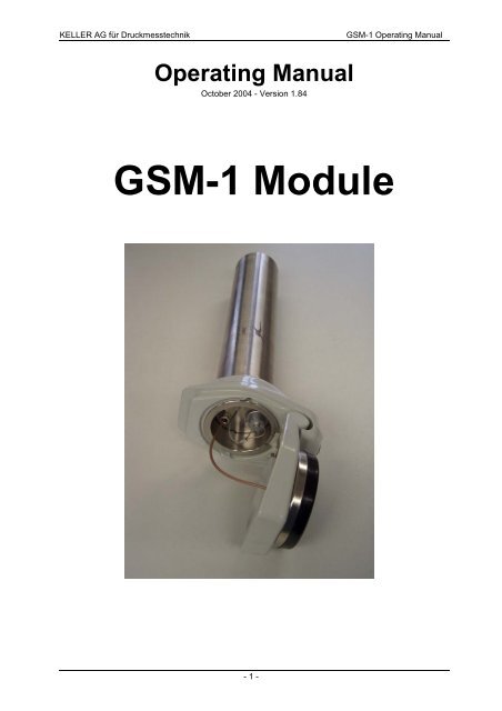
KELLER <strong>AG</strong> für Druckmesstechnik <strong>GSM</strong>-1 Operating Manual<br />
Operating Manual<br />
October 2004 - Version 1.84<br />
<strong>GSM</strong>-1 <strong>Module</strong><br />
- 1 -
KELLER <strong>AG</strong> für Druckmesstechnik <strong>GSM</strong>-1 Operating Manual<br />
Contents<br />
1 General .............................................................................................................3<br />
2 Using the Hardware for the first time .............................................................3<br />
2.1 Connecting the DCX-22 Data Logger .........................................................3<br />
2.2 Connecting the Series 30 Level Sensor......................................................5<br />
2.3 SIM Card.....................................................................................................6<br />
2.4 Power Supply..............................................................................................7<br />
2.5 Flat Antenna ...............................................................................................9<br />
2.6 Antenna for SMA Connection ...................................................................11<br />
3 Configuration of the <strong>Module</strong> .........................................................................12<br />
3.1 General Settings .......................................................................................12<br />
3.2 Example Working Settings........................................................................14<br />
3.3 Remaining Configurations.........................................................................18<br />
3.4 Monitoring.................................................................................................22<br />
4. Data connection.............................................................................................24<br />
4.1 Preparation for connecting the call ...........................................................24<br />
5. Acknowledgement via E-mail or Fax............................................................26<br />
5.1 Send E-mail ..............................................................................................26<br />
5.2 Send Fax ..................................................................................................27<br />
6. Accessories....................................................................................................28<br />
- 2 -
KELLER <strong>AG</strong> für Druckmesstechnik <strong>GSM</strong>-1 Operating Manual<br />
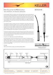
1 GENERAL<br />
This <strong>GSM</strong>-1 unit is a battery-operated module for the remote transmission of sensor<br />
data. It has been specially designed for connecting to KELLER data loggers and level<br />
sensors. The data is transmitted by SMS, e-mail or fax.<br />
2 USING THE HARDWARE FOR THE FIRST TIME<br />
2.1 Connecting the DCX-22 Data Logger<br />
The DCX-22 data logger can be directly bolted on to the casing of the module (1). To<br />
do this, it is first necessary to remove the knurled nut. The O-ring (2) (see Accessories,<br />
Product No.: 508610.0024) must be used to ensure a watertight seal between the two<br />
components. When the DCX has been bolted on, the knurled nut can be screwed back<br />
on and tightened (Figure. 2)<br />
2 1<br />
Fig. 1: Connecting the DCX-22 data logger<br />
- 3 -
KELLER <strong>AG</strong> für Druckmesstechnik <strong>GSM</strong>-1 Operating Manual<br />
The data connection is made by means of the Fischer plug connector. In the module,<br />
the corresponding connector cable (Accessory No.: 320020.0009) is already connected<br />
to the green terminal.<br />
Brown lead : Terminal A<br />
White lead: Terminal B<br />
To insert the plug connector, the battery must first be removed from the battery holder.<br />
When plugging in the connector, the engraved line on the plug body must be aligned<br />
with the red dot on the sleeve terminal (reverse polarity protection).<br />
Knurled nut<br />
Fig. 2: Data connection to the DCX-22 data logger<br />
- 4 -<br />
Red dot<br />
Engraved line
KELLER <strong>AG</strong> für Druckmesstechnik <strong>GSM</strong>-1 Operating Manual<br />
2.2 Connecting the Series 30 Level Sensor<br />
To connect a Series 30 level sensor, the adaptor socket (see Accessories, Product<br />
No.: 320020.0007) is required. Feed the sensor cable through the sleeve, and connect<br />
the relevant cable ends to the terminal strip in accordance with the following arrangement:<br />
blue: A<br />
yellow: B<br />
white: GND<br />
black: +V<br />
Fig. 3: Data connection to the level sensor<br />
The adaptor sleeve has to be tightened very well with an open-ended spanner,<br />
because the whole weight of the level sensor has to be carried by this adaptor<br />
sleeve.<br />
If a level sensor with a reference tube is used, the adaptor sleeve with hole (see Accessories,<br />
Product No.: 320020.0008) must be used. The hole guarantees that the air<br />
pressure inside the case is the same as the air pressure outside the case (pressure<br />
equalisation).<br />
- 5 -
KELLER <strong>AG</strong> für Druckmesstechnik <strong>GSM</strong>-1 Operating Manual<br />
2.3 SIM Card<br />
As with a mobile phone, a SIM card is required to transfer data. We recommend the<br />
use of a prepaid card. In this way, if the configuration is incorrect, only the amount of<br />
credit on the card can be used.<br />
Before starting to use the SIM card, all SMS messages still on the card should be deleted<br />
(both sent and received SMS).<br />
Abb. 4a: <strong>GSM</strong>-1 without SIM interlock Abb. 4b: <strong>GSM</strong>-1 with SIM interlock<br />
4<br />
The SIM card [4] is pushed as far as it will go into the slot which can be found between<br />
the two printed circuit boards (check for the gap). The gold contacts on the SIM card<br />
must face down. For <strong>GSM</strong>-1 without SIM interlock the chamfer is on the right hand<br />
side, for <strong>GSM</strong>-1 with SIM interlock [5] the card has to be inserted chamfer first (see<br />
Fig. 4a and 4b).<br />
Ensure that there is always sufficient credit on your card. Your telephone provider will<br />
tell you about the various possibilities for topping up credit.<br />
- 6 -<br />
5<br />
4
KELLER <strong>AG</strong> für Druckmesstechnik <strong>GSM</strong>-1 Operating Manual<br />
2.4 Power Supply<br />
To power the unit, the black four-pole battery plug must be connected to the corresponding<br />
socket on the circuit board. Ensure that the plug tab is pointing down (see<br />
Fig. 5).<br />
Fig. 5: Inserting the battery<br />
Now push the battery into the battery clip as shown in Fig. 6. The grey cable from the<br />
data logger runs in the slot in the battery clip (see also Fig. 2).<br />
Fig. 6: Inserting the battery<br />
- 7 -<br />
Tab down
KELLER <strong>AG</strong> für Druckmesstechnik <strong>GSM</strong>-1 Operating Manual<br />
Battery life:<br />
The battery life is greatly dependent on the configuration of the <strong>GSM</strong>-1: how many<br />
SMS messages are sent per week, whether data connections are made, etc. A total of<br />
around 3,000 SMS messages can be sent with one battery, or 30 hours data connection<br />
used. New batteries can be ordered from KELLER <strong>AG</strong> (see Accessories, Product<br />
No.: 557005.0012).<br />
- 8 -
KELLER <strong>AG</strong> für Druckmesstechnik <strong>GSM</strong>-1 Operating Manual<br />
2.5 Flat Antenna<br />
Either the supplied flat antenna (see Accessories, Product No.: 320020.0004) or any<br />
other antenna with an SMA connection can be used.<br />
If you wish to use the flat antenna, we advise you to first completely unscrew the cover,<br />
using an Allen key. This allows the upper part and lower parts of the cover to be prepared<br />
separately. The antenna cable on the upper part of the cover is now fed through<br />
the conduit gland (6), two washers (7) and the seal (8) into the inside of the unit and<br />
pressed into its counterpart piece (9) until it engages.<br />
6<br />
7<br />
8<br />
9<br />
Fig. 7: Connecting the flat antenna<br />
Please ensure that the conduit gland is properly screwed in, to ensure that no water<br />
penetrates into the inside of the unit. The conduit gland must be properly tightened.<br />
- 9 -
KELLER <strong>AG</strong> für Druckmesstechnik <strong>GSM</strong>-1 Operating Manual<br />
Use the cable clip to secure the plug (Fig. 8).<br />
Fig. 8: Securing the antenna cable<br />
A bag containing silicate desiccant is used to protect the sensitive electronics from<br />
humidity. Push this bag together with the <strong>GSM</strong> module into the sleeve. Ensure that the<br />
holes (10) on the top of the casing are completely visible. These are provided to allow<br />
water to drain off, so that it does not collect inside the unit.<br />
10<br />
Fig. 9: Fitting the <strong>GSM</strong>-1 module in the sleeve<br />
The bottom part of the cover is fitted at the installation site. The module can now be installed,<br />
together with the appropriate sensor, at the measuring point, and secured in<br />
place by screwing on the upper cover.<br />
- 10 -
KELLER <strong>AG</strong> für Druckmesstechnik <strong>GSM</strong>-1 Operating Manual<br />
2.6 Antenna for SMA Connection<br />
This can be connected by means of the supplied adapter cable (see Accessories,<br />
Product No.: 320020.0006).<br />
It is also possible to use a stub antenna (see Accessories, Product No.: 320020.0003).<br />
If the adapter cable is used, this should be protected by means of the supplied shrink<br />
sleeve. The small shrink sleeve is pulled over the rear part of the SMA plug, and the<br />
large shrink sleeve over the entire connection (see Fig. 10). The shrink sleeves are<br />
now heated uniformly with a hot-air gun. This protects the unit from the ingress of dirt<br />
and moisture.<br />
To feed the plug on the other end of the cable into the unit, first unscrew the conduit<br />
gland from the unit (see installation of the flat antenna).<br />
The <strong>GSM</strong> module is then pushed into the sleeve (see installation of the flat antenna).<br />
If it is now necessary to configure the pressure transmitter (level adjustment), this can<br />
be done directly with the converter cable via the plug on the <strong>GSM</strong>-1. The data is<br />
transmitted from the <strong>GSM</strong> module direct to the pressure transmitter.<br />
Fig. 10: Connection of the stub antenna<br />
- 11 -
KELLER <strong>AG</strong> für Druckmesstechnik <strong>GSM</strong>-1 Operating Manual<br />
3 CONFIGURATION OF THE MODULE<br />
3.1 General Settings<br />
The <strong>GSM</strong>-1 can be configured at any time. To carry out the configuration, plug the battery<br />
into the module and connect it to your PC via the K-103A or K-104A converter.<br />
ATTENTION:<br />
Once the module has been configured, it must not be disconnected from the<br />
power supply. This would result in the loss of parts of the configuration!<br />
12<br />
13<br />
14<br />
19<br />
21<br />
15<br />
20<br />
Fig. 11: Configuration<br />
- 12 -<br />
11<br />
18<br />
17<br />
16
KELLER <strong>AG</strong> für Druckmesstechnik <strong>GSM</strong>-1 Operating Manual<br />
The following information on the “Settings” register card is essential for configuring the<br />
unit. To configure the unit, start up the configuration software: “<strong>GSM</strong>-1 Setup” and click<br />
through the options.<br />
11<br />
12<br />
13<br />
14<br />
15<br />
16<br />
17<br />
18<br />
19<br />
20<br />
This is used to select the language.<br />
Comport number:<br />
This is used for determining the serial port to which you have connected the<br />
module via the converter<br />
Connect:<br />
When this button is pressed, the module is automatically recognised. If it is not<br />
recognised, the message Communication error is displayed.<br />
Read configuration:<br />
Press this button to read the current configuration.<br />
<strong>GSM</strong>-1 time:<br />
This is used to set the current date and time. Press the Write button to save these<br />
values in the <strong>GSM</strong>-1. Attention: these values are lost if the power supply is disconnected!<br />
To read the current time in the <strong>GSM</strong>, press Read.<br />
Connected device:<br />
This is used to select the connected measuring device. The <strong>GSM</strong>-1 can be connected<br />
to a DCX-22 or a Series 30.<br />
SIM PIN:<br />
If your SIM card is protected by a PIN, enter the PIN at this point.<br />
SMS-Service-Center-Number:<br />
Enter the telephone number of your telephone company's SMS center here. SMS<br />
messages cannot be sent without this number!<br />
Save CH:<br />
This is used to highlight the channels, from which you wish to save the values.<br />
The values will be received in an SMS in listed order. The exception is the<br />
Info-SMS, where all values will be sent.<br />
Channel resolution:<br />
The resolution is set as standard for five-character pressure values and fourcharacter<br />
temperature values. The decimal point is counted as a character.<br />
Channel multiplier:<br />
This is used to enter a factor for other units. The unit [bar] is pre-entered as standard<br />
for pressure values. To change the unit to [mbar], the factor must be set at<br />
1,000 (1 bar = 1,000 mbar). This arrangement allows the creation of individual<br />
units, such as may occur due to different liquid densities.<br />
Channel unit:<br />
This unit is dependent on the factor: e.g. [mbar] for pressure or [°C] for temperature.<br />
- 13 -
KELLER <strong>AG</strong> für Druckmesstechnik <strong>GSM</strong>-1 Operating Manual<br />
21<br />
Enabled functions:<br />
Click on the various options to add the relevant register cards to the user interface.<br />
The corresponding settings can then be made via the relevant register<br />
cards (see Fig.: 12).<br />
3.2 Example Working Settings<br />
The following example is intended to illustrate the settings that are required to allow the<br />
unit to carry out two measurements every day and transmit the measured data by SMS. In<br />
addition, a check is to be made every day at 8.30 a.m. for whether the <strong>GSM</strong>-1 has received<br />
any commands via SMS.<br />
• Settings register card: see also the above explanations<br />
21<br />
Enable functions: Highlight the “Check SMS”, “Measure SMS” and “Data<br />
connection” functions. The relevant register cards can now be selected.<br />
• Check SMS register card: (to check for received commands)<br />
26<br />
22<br />
24<br />
25<br />
Fig. 12: Check SMS register card<br />
- 14 -<br />
23<br />
Register cards
KELLER <strong>AG</strong> für Druckmesstechnik <strong>GSM</strong>-1 Operating Manual<br />
22<br />
23<br />
24<br />
25<br />
26<br />
Next action:<br />
Enter the date and time when an SMS is to be accessed the first time, e.g. 8.30<br />
a.m. (08:30:00)<br />
Interval:<br />
Enter the time interval at which the messages are to be accessed (e.g. 1 day).<br />
SMS access password:<br />
If you enter a password here, only those messages will receive a reply which begin<br />
with this password (case sensitive!). It is advisable to use a password, as otherwise<br />
replies will also be sent to SMS messages from the provider (e.g. SMS<br />
charges and advertising SMS messages).<br />
Supported Commands:<br />
An instruction is a character. If this character is transmitted from any mobile<br />
phone to the <strong>GSM</strong> module, the <strong>GSM</strong> module carries out the corresponding task.<br />
For example, if an SMS, with the text “password i”, is sent to the <strong>GSM</strong>-1 telephone<br />
number, then the next time the SMS messages are accessed, the module<br />
returns an SMS with the current measured values to the sender (in this case,<br />
“password” stands for any password to be freely selected by the user. This is entered<br />
in the SMS access password field.).<br />
Text, which is send by the command “?”: This text is sent as a reply SMS. The<br />
current measured values are automatically appended to this text.<br />
Configuration with password “KELLER”<br />
and reply text:<br />
- 15 -<br />
Query with password and command “?”:<br />
Reply to query. Pressure (in mbar) and temperature<br />
with positive/negative sign separately:
KELLER <strong>AG</strong> für Druckmesstechnik <strong>GSM</strong>-1 Operating Manual<br />
27<br />
28<br />
29<br />
30<br />
Measure SMS register card: (for transmission of the data)<br />
29<br />
27<br />
30<br />
Fig. 13: “Measure SMS” register card<br />
Next action:<br />
Enter the time for the first measurement.<br />
Interval:<br />
Enter the time interval at which the measurement is to be repeated (e.g. 12 h)<br />
Send SMS after X measurements:<br />
After how many measurements an SMS is to be sent with the measured data<br />
(e.g. 2)<br />
Measure/Save SMS-Text + Saved Data:<br />
The text entered here is placed at the start of the SMS message.<br />
- 16 -<br />
28
KELLER <strong>AG</strong> für Druckmesstechnik <strong>GSM</strong>-1 Operating Manual<br />
• Data connection register card<br />
ATTENTION:<br />
These settings must be made to allow a query to be made via a data connection,<br />
using Check SMS.<br />
31<br />
32<br />
32<br />
31<br />
Fig. 14: “Data connection” register card<br />
Call-back Number:<br />
Enter the number of the modem which you wish to contact.<br />
Modem Protocol:<br />
The data protocol used by the called modem.<br />
When you have completed this, return to the Settings register card:<br />
Under Enable functions delete the flag of Data connection. Finally, press Write configuration.<br />
The settings are now written to the unit. The required configurations are made, and the<br />
<strong>GSM</strong>-1 is set to working mode.<br />
- 17 -
KELLER <strong>AG</strong> für Druckmesstechnik <strong>GSM</strong>-1 Operating Manual<br />
3.3 Remaining Configurations<br />
The remaining configuration possibilities, which were not included in the above example,<br />
are explained below.<br />
• Settings register card (see Fig. 11)<br />
21<br />
Enable functions:<br />
Highlight all functions.<br />
• Alarm SMS register card<br />
This is used for defining an alarm condition. When this occurs, an SMS is sent. The<br />
alarm condition can result from values in excess of or below a particular measured<br />
value or from a defined change of a parameter (pressure or temperature).<br />
42<br />
33 34<br />
36 37<br />
35<br />
38 39 40<br />
41<br />
Fig. 15: “Alarm SMS” register card<br />
- 18 -
KELLER <strong>AG</strong> für Druckmesstechnik <strong>GSM</strong>-1 Operating Manual<br />
33<br />
34<br />
35<br />
36<br />
37<br />
38<br />
39<br />
Next action:<br />
Enter the time when the alarm condition is to be checked for the first time.<br />
Interval:<br />
Enter the time interval at which the channels are to be measured and the alarm<br />
condition checked.<br />
Send Alarm-SMS X times:<br />
How often an SMS message is to be sent when the alarm condition occurs (only<br />
with On/Off alarm)<br />
Alarm-Channel:<br />
Enter the channel which is to be checked.<br />
Alarm-Type:<br />
On/Off hysteresis or value change (Delta/time: pressure or temperature change<br />
between two measurements)<br />
Alarm On-Value:<br />
With the On/Off type of the switch-on value in the unit specified in Settings (only<br />
with On/Off alarm)<br />
Alarm Off-Value:<br />
With the On/Off type of the switch-off value in the unit specified in Settings (only<br />
with On/Off alarm)<br />
If the switch-on value is greater than the switch-off value, the alarm is triggered<br />
when the switch-on value is exceeded.<br />
If the switch-off value is greater than the switch-on value, the alarm is triggered<br />
when the signal falls below the switch-off value.<br />
40<br />
41<br />
42<br />
Alarm delta/interval:<br />
The minimum value by which a parameter must have changed since the last<br />
alarm measurement to trigger the alarm. The parameter must be specified as a<br />
positive value. This value then applies both to positive and negative changes by<br />
this amount.<br />
SMS-Number:<br />
Number of the mobile phone to which the alarm SMS is to be sent.<br />
Alarm SMS-Text:<br />
The text to precede the measured values<br />
- 19 -
KELLER <strong>AG</strong> für Druckmesstechnik <strong>GSM</strong>-1 Operating Manual<br />
• Info SMS register card<br />
The info SMS is used to transmit the antenna signal strength (range: 0 – 31, with 31<br />
representing maximum reception), battery capacity and all measured values.<br />
43<br />
44<br />
45<br />
45<br />
43<br />
Fig. 16: “Info SMS” register card<br />
Next action:<br />
Enter the time when the first info SMS is to be sent.<br />
Interval:<br />
The time interval at which info SMS are to be sent.<br />
SMS-Number:<br />
The mobile phone number to which the SMS is to be sent.<br />
- 20 -<br />
44
KELLER <strong>AG</strong> für Druckmesstechnik <strong>GSM</strong>-1 Operating Manual<br />
• Data connection register card<br />
This function is used to make a data connection between a PC and the operating module,<br />
allowing direct communication with the connected sensor. A modem is required for<br />
this purpose. Further information can be found under “Data Connection”.<br />
46<br />
47<br />
48<br />
49<br />
49<br />
46<br />
Fig. 17: “Data connection” register card<br />
Next action:<br />
Enter the first time a data connection is to be made.<br />
48<br />
Interval:<br />
The time interval at which a data connection is to be made.<br />
Call-back Number:<br />
The telephone number of the modem to be called to make a data connection.<br />
Modem Protocol:<br />
The data protocol with which the user’s modem works.<br />
- 21 -<br />
47
KELLER <strong>AG</strong> für Druckmesstechnik <strong>GSM</strong>-1 Operating Manual<br />
3.4 Monitoring<br />
• Error/Status register card<br />
The Error/Status register card is used to monitor the status of the module for diagnostic<br />
purposes. To update the values, read the configuration by means of the Read configuration<br />
function.<br />
50<br />
50<br />
52<br />
53<br />
Fig. 18: “Error/Status” register card<br />
Battery capacity:<br />
Displays the battery capacity as a percentage. If the value is below 30%, it is recommended<br />
to change the battery. Once the battery has been changed, the value<br />
is again shown as 99%. However, this is also the case each time power is restored<br />
after a disconnection. For this reason, the battery should be disconnected<br />
only for replacement.<br />
To ensure reliability, the battery should be replaced every four years.<br />
- 22 -<br />
51
KELLER <strong>AG</strong> für Druckmesstechnik <strong>GSM</strong>-1 Operating Manual<br />
48<br />
49<br />
50<br />
Send Info SMS:<br />
When you press this button, an Info SMS is sent to the receiver specified on the<br />
Info SMS register card, within 2 minutes. This is intended as a check when the<br />
system is installed on site.<br />
<strong>GSM</strong>-State:<br />
This shows the current mode of the modem. It also indicates whether a PIN is required<br />
to unlock the SIM card.<br />
Error state:<br />
If errors have occurred during operation, these are displayed in this function.<br />
To check the reception quality and battery capacity at any time, an SMS can be sent to the<br />
module. To do this, the password entered under Check SMS, followed by a space and “i”,<br />
must be entered (e.g. PASSW i). The next time SMS messages are accessed, an Info<br />
SMS is sent back to the mobile phone number from which the request was received.<br />
- 23 -
KELLER <strong>AG</strong> für Druckmesstechnik <strong>GSM</strong>-1 Operating Manual<br />
4. DATA CONNECTION<br />
When a data connection is established, the data from the sensor connected to the <strong>GSM</strong>-1<br />
can be accessed world-wide via modem. If a data logger is connected, the entire memory<br />
content can be read out. It is also possible to reconfigure the logger.<br />
A data connection can be made only from the module. The user is always called from the<br />
<strong>GSM</strong> module. The call time can be specified in the configuration. An additional, more flexible<br />
possibility is to send an SMS to the module, which requests a data connection (with the<br />
instruction “
KELLER <strong>AG</strong> für Druckmesstechnik <strong>GSM</strong>-1 Operating Manual<br />
Manual read-out<br />
“HyperTerminal” can be used to check that the data connection is being correctly<br />
made. This program can be found in Windows 2000 at:<br />
Start � Programs � Accessories � Communications<br />
Any entry can be made for the name. It is important to specify the serial port (COM) of<br />
the modem for the setting, “Connect via”. The following connection settings must be<br />
used:<br />
- Bits per second: 9600<br />
- Data bits: 8<br />
- Parity: none<br />
- Stop bits: 1<br />
- Flow control: none<br />
HyperTerminal can also be used to configure the modem. The command ATS0 = 2 can<br />
be used to specify the number of rings before the modem answers. The figure (in this<br />
case 2) is the number of rings.<br />
When the modem is called, and the data connection made, a check can be made<br />
whether everything is operating correctly. Once the connection has been made, the<br />
message: “Connection OK” is transmitted. “HyperTerminal” can now be closed and the<br />
sensor software (reader, writer) can be started. The COM port of the modem must be<br />
entered, and modem operation activated under Connection settings.<br />
Communication can now be carried out with the data logger connected to the module,<br />
as though this were directly connected to the PC. If no data is requested for more than<br />
1 minute, the <strong>GSM</strong> module automatically terminates the data connection.<br />
Using “Modem-Adjust” to reset the zero point<br />
The “Modem-Adjust” program allows the zero<br />
point of the transmitter connected to the<br />
<strong>GSM</strong>-1 to be reset from the office PC via modem.<br />
The connection is made manually as<br />
described in the above passage.<br />
The serial port to which the modem is connected<br />
must be entered in the program. The<br />
“Init” command reads the configuration of the<br />
transmitter. The new level can now be set for<br />
the required measurement channel. “Set to<br />
New Value” is used to set the entered value<br />
to the current level. “Set to Zero” sets the current<br />
level as the zero point, and “Set Factory<br />
Value” resets the original factory settings.<br />
Once “Init” has been selected, the current<br />
pressure value of the transmitter is permanently<br />
read out and displayed.<br />
The modem connection remains constantly active, and is not disconnected until<br />
the program is exited!<br />
- 25 -
KELLER <strong>AG</strong> für Druckmesstechnik <strong>GSM</strong>-1 Operating Manual<br />
5. ACKNOWLEDGEMENT VIA E-MAIL OR FAX<br />
Instead of receiving an acknowledgement via SMS, this data can also be received via email<br />
or fax. However, the data is sent via SMS. The procedure is dependent on the telephone<br />
provider (SIM card). Details of whether e-mails or faxes are possible can be found<br />
on the web site of your telephone provider. Our examples are based on the “Swisscom”<br />
service:<br />
5.1 Send E-mail<br />
If you wish to receive the SMS as a e-mail, select the telephone number 555 as the SMS<br />
number. The e-mail address of the recipient is then entered at the start of the SMS text.<br />
This is followed by a space and then the actual text.<br />
Fig. 19: “SMS text“<br />
- 26 -
KELLER <strong>AG</strong> für Druckmesstechnik <strong>GSM</strong>-1 Operating Manual<br />
5.2 Send Fax<br />
The fax number is entered as the SMS number, and “*FAX#” is entered at the start of the<br />
text. This is followed by a space and then the actual text.<br />
Fig. 20: “Fax text”<br />
Further information is available on the Swisscom web site at:<br />
http://www.swisscom-mobile.ch/sp/GDAAAAAA-de.html<br />
Different providers have different procedures!!<br />
- 27 -
KELLER <strong>AG</strong> für Druckmesstechnik <strong>GSM</strong>-1 Operating Manual<br />
6. ACCESSORIES<br />
Description Delivery<br />
Package<br />
Adapter cable SMA � MMCX with shrink<br />
sleeves<br />
Stub antenna<br />
with SMA connection<br />
Flat antenna with cover<br />
O-ring<br />
∅17x1.5<br />
Adapter with rubber seal for connection<br />
of a Series 30<br />
Adapter with rubber seal for connection<br />
of a Series 30<br />
with hole for air pressure equalisation<br />
Optional<br />
Optional<br />
Optional<br />
Optional<br />
Optional<br />
Optional<br />
Modem adapter for data connection Optional<br />
- 28 -<br />
Image<br />
Product No.<br />
320020.0006<br />
320020.0003<br />
320020.0004<br />
508610.0024<br />
320020.0007<br />
320020.0008<br />
320020.0005
KELLER <strong>AG</strong> für Druckmesstechnik <strong>GSM</strong>-1 Operating Manual<br />
<strong>GSM</strong>-1 CD<br />
CD includes:<br />
Configuration program: <strong>GSM</strong>-1 Setup,<br />
Modem-Reader, Modem-Adjust,<br />
Operating manual<br />
The software can also be downloaded<br />
free from the Internet!<br />
� www.keller-druck.com<br />
(at “Products” – “Miscellaneous/Software”<br />
“<strong>GSM</strong>-1”)<br />
K-103A interface converter<br />
For communication between the<br />
PC and <strong>GSM</strong>-1.<br />
Connection to a serial port<br />
(RS 232 – RS 485 converter)<br />
K-104A interface converter<br />
For communication between the<br />
PC and <strong>GSM</strong>-1.<br />
Connection to a USB-port<br />
(USB – RS 485 converter)<br />
Plug cable for connection of a data<br />
logger (DCX-22)<br />
Battery 3.6V with plug<br />
Capacity: 16.5 Ah<br />
Optional<br />
Optional<br />
Optional<br />
Included<br />
Included<br />
- 29 -<br />
239005.0002<br />
309010.0002<br />
309010.0009<br />
320020.0009<br />
557005.0012