DIGITAL DISPLAY PAXD
- 5 digits, 14 mm high LEDs, a nnunciators - for potentiometer inputs - 20 measurements per second - 3 programmable user inputs - Protection class IP65 (front side) - Working temperature 0 to 50 °C, - Easy programming directly, or via PC - Plug-in output-cards: analog, USB, RS485, Relay (thresholds), Transistor, RS232, Profibus - Summation, min-/max value display - 16 point linearisation
- 5 digits, 14 mm high LEDs, a
nnunciators
- for potentiometer inputs
- 20 measurements per second
- 3 programmable user inputs
- Protection class IP65 (front side)
- Working temperature 0 to 50 °C,
- Easy programming directly, or via PC
- Plug-in output-cards: analog, USB, RS485,
Relay (thresholds), Transistor, RS232, Profibus
- Summation, min-/max value display
- 16 point linearisation

You also want an ePaper? Increase the reach of your titles
YUMPU automatically turns print PDFs into web optimized ePapers that Google loves.
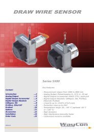
<strong>DIGITAL</strong> <strong>DISPLAY</strong><br />
for Industry Applications<br />
Series <strong>PAXD</strong><br />
Key-Features:<br />
Content:<br />
Technical Data<br />
….2<br />
Technical Drawing ....2<br />
Electrical Connection ....3<br />
Plug-In Cards ....4<br />
Programming & Software ....5<br />
Order Code & Accessories ....6<br />
- 5 digits, 14 mm high LEDs, annunciators<br />
- for potentiometer inputs<br />
- 20 measurements per second<br />
- 3 programmable user inputs<br />
- Protection class IP65 (front side)<br />
- Working temperature 0 to 50 °C,<br />
- Easy programming directly, or via PC<br />
- Plug-in output-cards: analog, USB, RS485,<br />
Relay (thresholds), Transistor, RS232, Profibus<br />
- Summation, min-/max value display<br />
- 16 point linearisation<br />
17.12.14
- 2 -<br />
TECHNICAL DATA <strong>PAXD</strong><br />
Display<br />
Panel cut-out<br />
Annunciators<br />
Programmable user inputs<br />
Input signal<br />
Output signal (via plug-in cards)<br />
Serial Interfaces (via plug-in cards)<br />
Update rate<br />
Supply voltage<br />
Measurement rate<br />
Sensor supply<br />
Protection class<br />
Humidity<br />
Working temperature<br />
Housing<br />
Weight<br />
Electromagnetic compatibility<br />
Delivery<br />
5 digits, 14 mm high, red LEDs<br />
92 mm x 45 mm<br />
MAX, MIN, TOT (sum), SP1, SP2, SP3, SP4 (the respective output SP is active)<br />
3, logic state: jumper selectable for sink/source logic<br />
PNP: active V in >3.6 VDC, inactive V in
- 3 -<br />
ELECTRICAL CONNECTION <strong>PAXD</strong><br />
Connection<br />
1 AC Power Supply<br />
<strong>PAXD</strong>000B: 85 to 250 VAC<br />
<strong>PAXD</strong>001B: 11 to 36 VDC<br />
2 AC Power Supply<br />
<strong>PAXD</strong>000B: 85 to 250 VAC<br />
<strong>PAXD</strong>001B: 11 to 36 VDC<br />
3 VOLT/OHM Signal input+: Voltage/Resistance<br />
4 CURRENT Signal Input+: Current<br />
5 COMM. Signal Input GND<br />
6 +EXCITATION Sensor Supply 24 VDC/50 mA<br />
7 USER COMM GND User Input<br />
8 USER 1 User Input 1<br />
9 USER 2 User Input 2<br />
10 USER 3 User Input 3<br />
11 not connected<br />
Caution:<br />
Sensor input common is NOT isolated from user input common.<br />
In order to preserve the safety of the meter application, the<br />
sensor input common must be suitably isolated from hazardous<br />
live earth referenced voltages.<br />
JUMPER SETTINGS<br />
Before putting the meter into operation the jumper settings have to be checked and if needed adjusted<br />
The following points have to be set by the jumpers:<br />
●<br />
Input range jumper (factory setting +/-300 V)<br />
●<br />
Excitation output jumper (factory setting 24 V)<br />
●<br />
User input logic jumper (factory setting NPN)<br />
Indication of the jumper factory settings.<br />
<strong>PAXD</strong> CONNECTION TO A POTENTIOMETER<br />
Wiring diagram potentiometer (3 wires)<br />
●<br />
Terminal 3: Wiper/cursor<br />
●<br />
Terminal 5: Low end of pot.<br />
●<br />
Terminal 6: High end of pot.<br />
●<br />
Excitation Jumper: 2 V REF.<br />
●<br />
Input Range Jumper: 2 V<br />
●<br />
Programming Module 1 Input Range: 2 Volt<br />
Note: The Apply signal scaling style should be used<br />
because the signal will be in volts.
- 4 -<br />
PLUG-IN CARDS<br />
The display can be fitted with up to three optional plug-in cards. The details for each plug-in card can be reviewed in the specification section below. Only one card<br />
from each function type can be installed at one time. The plug-in cards can be installed initially or at a later date.<br />
Analog Output Card (retransmitted linear DC output): PAXCDL10<br />
●<br />
Types: 0 to 20 mA, 4 to 20 mA, or 0 to 10 VDC.<br />
●<br />
Isolation to sensor + user input commons: 500 Vrms for 1 min., working range 50V, not isolated from all other commons.<br />
●<br />
Accuracy: 0.17 % of FS (10 to 28 degree Celsius), 0.4% (0 to 50 degree Celsius)<br />
●<br />
Resolution 1/3500<br />
●<br />
Compliance: 10 VDC, 10 kOhm load min., 20 mA, 500 Ohm max. load<br />
Setpoint Alarm Output Cards<br />
Quad sourcing open collector card: PAXCDS40<br />
●<br />
4 isolated sourcing x PNP transistors<br />
●<br />
Internal suppy: 24 VDC +/- 10%, 30 mA max. total<br />
●<br />
Isolation to sensor + user input commons: 500 Vrms for 1 min., working range 50V, not isolated from all other commons.<br />
●<br />
External supply: 30 VDC max., 100 mA max. each output<br />
Quad sinking open collector card: PAXCDS30<br />
●<br />
4 isolated sinking x NPN transistors<br />
●<br />
Isolation to sensor + user input commons: 500 Vrms for 1 min., working range 50V, not isolated from all other commons.<br />
● Rating: 100mA max. at V sat =0,7 V max,, V max : 30V<br />
Dual relay card: PAXCDS10<br />
●<br />
2 x FORM-C relays, 5 A at 120/240 VAC or 28 VDC (Ohm load) at 120 VAC (80 VA inductive load)<br />
●<br />
Life expectancy: 100.000 cycles min. at full load.<br />
Quad relay card: PAXCDS20<br />
●<br />
4 x FORM-A relays, 3 A at 250 VAC or 30 VDC (Ohm load) at 120 VAC (80 VA inductive load)<br />
●<br />
Life expectancy: 100.000 cycles min. at full load.<br />
Interface Cards:<br />
●<br />
RS232, programmable, version with Sub-D connector: PAXCDC2C or with terminal: PAXCDC20<br />
●<br />
Multipoint RS485, programmable: PAXCDC10<br />
●<br />
DeviceNet, programmable: PAXCDC30<br />
●<br />
Profibus-DP: PAXCDC50<br />
Isolation 500V, not isolated from all other commons.<br />
USB CARD: PAXUSB00<br />
●<br />
only suited for slow measurement (for high dynamic measurement please use the RS232 card).<br />
●<br />
USB virtual COM Port<br />
●<br />
Connection: type mini B<br />
Installing plug-in cards:<br />
●<br />
With the display removed from the case, locate the plug-in card connector for the card type to be installed.<br />
The types are keyed by position with different main circuit board connector locations. When installing the<br />
card, hold the display by the rear terminals and not by the front display board. If installing<br />
the Quad sourcing card, set the jumper for internal or external supply operation before continuing.<br />
●<br />
Install the card by aligning the card terminals with the slot bay in the rear cover.<br />
●<br />
Slide the display back into the case. Be sure the rear cover latches fully into the case.<br />
●<br />
Apply the plug-in card label to the bottom side of the display in the designated area.
- 5 -<br />
PROGRAMMING<br />
Directly by the display keys<br />
<strong>DISPLAY</strong> MODE:<br />
The meter normally operates in the Display Mode. In this mode, the meter displays can be viewed consecutively by pressing the DSP key. The annunciators to the left<br />
of the display indicate which display is currently shown; Max Value (MAX), Min Value (MIN), or Totalizer Value (TOT). Each of these displays can be locked from view<br />
through programming. (See Module 3) The Input Display Value is shown with no annunciator.<br />
PROGRAMMING MODE:<br />
Two programming modes are available:<br />
Full Programming<br />
Mode permits all parameters to be viewed and modified. Upon entering this mode, the front panel keys change to Programming Mode operations. This mode should<br />
not be entered while a process is running, since the meter functions and User Input response may not operate properly while in Full Programming Mode.<br />
Quick Programming Mode<br />
permits only certain parameters to be viewed and/or modified. When entering this mode, the front panel keys change to Programming Mode operations, and all<br />
meter functions continue to operate properly. Quick Programming Mode is configured in Module 3. The Display Intensity Level d-LEu parameter is available in the<br />
Quick Programming Mode only when the security code is non-zero. For a description, see Module 9—Factory Service Operations. Throughout this document,<br />
Programming Mode (without Quick in front) always refers to “Full” Programming Mode<br />
By Software<br />
Additionally, the meters have a feature that allows a remote computer to directly control the outputs of the meter. With an RS232 or RS485 card installed, it is<br />
possible to configure the meter using a Windows® based program. The configuration data can be saved to a file for later recall.<br />
You will find a detailed description of the programming in the manual that is included in the delivery.<br />
PACKAGE FOR THE CONNECTION PAX TO PC<br />
SFCRUSB1<br />
Package for the connection of PAX displays to the USB interface of a PC:<br />
●<br />
includes USB plug-in card PAXUSB00<br />
●<br />
USB interface cable<br />
●<br />
Software Crimson 2: The Crimson software is a Windows based program that allows configuration of the PAX display from a PC. Crimson offers standard drop-down<br />
menu commands, that make it easy to program the meter. The meter’s program can then be saved in a PC file for future use. A PAX serial plug-in card or PAX USB<br />
programming card is required to program the meter using the software.<br />
Please keep in mind that the USB interface is limited in its speed of data transfer. In fast applications data might get lost. In such cases the faster RS232 interface<br />
should be chosen.<br />
Note: the USB interface is restricted in its ability to communicate with the Software ProLOG.<br />
ProLOG<br />
Analysis- and Visualisation software for Windows-based Systems<br />
Visualisation of the measurement data on a Windows PC, with the option of storing the data in a CSV file.<br />
HOUSING<br />
Aluminium housing GEH0IP65<br />
●<br />
black powder coating<br />
●<br />
internal grounding terminal.<br />
●<br />
protection class: IP65<br />
●<br />
dimensions: (W x H x D) 168 mm x 83 mm x 220 mm<br />
●<br />
delivery: housing, mounting material<br />
●<br />
without cable passages (must be drilled individually)<br />
Table housing TG9648<br />
●<br />
The housing is suited for all displays with front dimensions 96 x 48 mm<br />
●<br />
self assembly<br />
●<br />
dimensions: (W x H x D) 114 mm x 62 mm x 176 mm<br />
●<br />
delivery: housing, mounting material
- 6 -<br />
ORDER CODES<br />
<strong>PAXD</strong>000B<br />
<strong>PAXD</strong>001B<br />
Voltage supply: 85 to 250 VAC<br />
Voltage supply: 11 to 36 VDC/24 VAC<br />
ACCESSORIES<br />
Plug-in cards<br />
Software<br />
PAXCDC10 Serial communication card RS485 Crimson 2 on request<br />
PAXCDC20 Serial communication card RS232, terminal ProLOG on request<br />
PAXUSB00 Interface card USB<br />
PAXCDC50 Interface card PROFIBUS-DP Packages<br />
PAXCDL10 Analog output card SFCRUSB1 includes USB plug-in card PAXUSB00<br />
PAXCDS10 Dual relay, Form-C, normally open & closed USB interface cable<br />
PAXCDS20 Quad relay, Form-A, normally open only Software Crimson 2<br />
PAXCDS30<br />
PAXCDS40<br />
PAXCDC2C<br />
Quad sinking NPN open collector<br />
Quad sourcing PNP open collector<br />
Serial communication card RS232, 9 pole SUB-D connector<br />
Miscellaneous<br />
Housings<br />
PAXLBK11 Units label kit GEH0IP65 Aluminium housing, IP65<br />
Einstellung Pre-adjustment according to customer demands TG9648 Table housing<br />
Subject to change without prior notice.<br />
WayCon Positionsmesstechnik GmbH<br />
email: info@waycon.de<br />
internet: www.waycon.de<br />
Head Office<br />
Mehlbeerenstr. 4<br />
82024 Taufkirchen<br />
Tel. +49 (0)89 67 97 13-0<br />
Fax +49 (0)89 67 97 13-250<br />
Office Köln<br />
Auf der Pehle 1<br />
50321 Brühl<br />
Tel. +49 (0)2232 56 79 44<br />
Fax +49 (0)2232 56 79 45