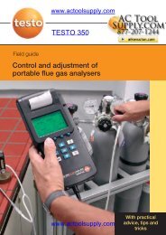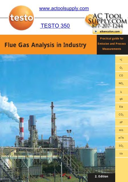
Testo 350 Field Guide - Actoolsupply.com
Testo 350 Field Guide - Actoolsupply.com
Testo 350 Field Guide - Actoolsupply.com

You also want an ePaper? Increase the reach of your titles
YUMPU automatically turns print PDFs into web optimized ePapers that Google loves.
www.actoolsupply.<strong>com</strong><br />
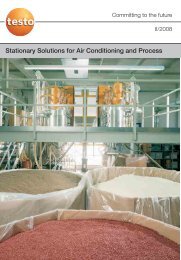
Flue Gas Analysis in Industry<br />
Practical guide for<br />
Emission and Process<br />
Measurements<br />
°C<br />
O 2<br />
CO<br />
NO x<br />
<br />
qA<br />
Eta<br />
CO 2<br />
∆P<br />
m/s<br />
m 3 /h<br />
SO 2<br />
t/a<br />
2. Edition
www.actoolsupply.<strong>com</strong><br />
www.actoolsupply.<strong>com</strong>
www.actoolsupply.<strong>com</strong><br />
Content<br />
1. Foreword 5<br />
2. The <strong>com</strong>bustion process 6<br />
2.1 Energy and <strong>com</strong>bustion 6<br />
2.2 Combustion plants 8<br />
2.3 Fuels 9<br />
2.4 Combustion air; excess air value 10<br />
2.4.1 Stoichiometric and excess-air <strong>com</strong>bustion; material balance 10<br />
2.4.2 Determination of the excess air value 12<br />
2.4.3 Required <strong>com</strong>bustion air volume 14<br />
2.4.4 Gas volume; dilution effect; reference values 14<br />
2.5 Flue gas 16<br />
2.6 Calorific value; efficiency; flue gas loss 19<br />
2.7 Dew point; condensate 22<br />
3. Analysis of process gases in industry 25<br />
3.1 Combustion optimization 27<br />
3.2 Process control 30<br />
3.2.1 Firing plants 30<br />
3.2.2 Industrial furnaces 31<br />
3.2.3 Thermochemical surface treatment 31<br />
3.2.4 Safety measurements 32<br />
3.3 Emission control 33<br />
3.3.1 Legal basis in Germany 33<br />
3.3.2 Legal instructions in Germany 35<br />
3.3.3 Emission Monitoring in the USA 41<br />
3.3.4 Flue gas cleaning 44<br />
4. Gas analysis technique 47<br />
4.1 Terms of gas analysis (selection) 47<br />
4.1.1 Concentrations; concentration conversions 47<br />
4.1.2 Sample conditioning 52<br />
4.1.3 Cross-sensitivity 54<br />
4.1.4 Calibration 55<br />
4.2 Gas analysis 56<br />
4.2.1 Terms; application areas; analyzers; sensors 56<br />
4.2.2 Measuring principles (used by <strong>Testo</strong>) 61<br />
5. Application of <strong>Testo</strong> gas analyzers 70<br />
5.1 Power generation 71<br />
5.1.1 Solid-fuel-fired furnaces 71<br />
5.1.2 Gas-fired furnaces 73<br />
5.1.3 Gas turbine plants 74<br />
www.actoolsupply.<strong>com</strong><br />
3
www.actoolsupply.<strong>com</strong><br />
Content<br />
5.1.4 Oil-fired furnaces 76<br />
5.1.5 Coal-fired power station 77<br />
5.1.6 Combined heating and power stations 79<br />
5.1.7 Gas and steam power stations 81<br />
5.2 Waste disposal 82<br />
5.2.1 Waste incineration 82<br />
5.2.2 Waste pyrolysis 85<br />
5.2.3 Thermal gas incineration 86<br />
5.3 Stone and clay industry 88<br />
5.3.1 Cement production 88<br />
5.3.2 Ceramic/Porcelain production 90<br />
5.3.3 Production of bricks 92<br />
5.3.4 Glass production 93<br />
5.3.5 Production of quicklime 96<br />
5.4 Metal industry 98<br />
5.4.1 Processing of ores 98<br />
5.4.2 Iron production 99<br />
5.4.3 Production of raw steel 101<br />
5.4.4 Coke oven plant 102<br />
5.4.5 Aluminum production 104<br />
5.4.6 Surface treatment 105<br />
5.5 Chemical/petrochemical industry 107<br />
5.5.1 Process heater 107<br />
5.5.2 Refineries 108<br />
5.5.3 Flares 110<br />
5.5.4 Residues incineration 111<br />
5.6 Others 113<br />
5.6.1 Crematoria 113<br />
5.6.2 Engine test beds 113<br />
6. <strong>Testo</strong> gas analyzer 115<br />
6.1 The <strong>com</strong>pany 115<br />
6.2 Characteristic analyzer features 117<br />
6.3 Industrial gas analyzers (overview) 120<br />
6.4 Gas analyzer accessories (overview) 123<br />
6.5 Technical description and data (Selection) 126<br />
Index 134<br />
Address list 137<br />
4<br />
www.actoolsupply.<strong>com</strong>
www.actoolsupply.<strong>com</strong><br />
Foreword<br />
1. Foreword<br />
This handbook is a valuable reference work for the application of portable flue gas<br />
analyzer in industry. Frequent questions arising from practical use are answered<br />
based on the worldwide experience of many thousands of testo analyzer users.<br />
The handbook will save you the time consuming and sometimes difficult search<br />
for information in various sources.<br />
What is missing? What was not described as detailed as required?<br />
Your <strong>com</strong>ments, amendments and suggestions are very much appreciated!<br />
They will be incorporated into a next edition. Just write to us; see the form for that<br />
on page 138.<br />
We thank Dr. Ulrich Jecht for his <strong>com</strong>mitment in writing this handbook.<br />
The Management<br />
Burkart Knospe<br />
Lothar Walleser<br />
www.actoolsupply.<strong>com</strong><br />
5
www.actoolsupply.<strong>com</strong><br />
2. The <strong>com</strong>bustion process<br />
2.1 Energy and <strong>com</strong>bustion<br />
Energy<br />
is defined as the ability of a material or system to perform labor. Energy exists in<br />
different modifications which can be classified into six categories as follows:<br />
• Mechanical energy (flowing water, driving car)<br />
• Thermal energy (boiling water, gas flame)<br />
• Chemical energy (chemical reaction, burning process, explosion)<br />
• Electrical energy (car battery, electricity)<br />
• Electromagnetic energy (light radiation, microwave radiation)<br />
• Nuclear energy (nuclear fission)<br />
The different energy modifications can be converted into each other, within an<br />
ideally closed system, with the sum remaining constant (conservation of energy).<br />
In practice, however, energy losses occur during the conversion process thereby<br />
reducing the efficiency.<br />
The natural energy carriers (coal, natural gas, crude oil, sun radiation, water<br />
power etc.) are described as primary energies, while the term secondary energies<br />
stands for what is received from energy conversions (electricity, heat, etc.). Energy<br />
carriers differ in energy content. For <strong>com</strong>parison reasons the energy content<br />
is described as amount of energy which could be released from a certain<br />
quantity of an energy carrier in case of its total <strong>com</strong>bustion. The energy scale unit<br />
is 1 Joule [J]. Some energy content values are given in table 1.<br />
Energy carrier, 1 kg of... Energy content [MJ]<br />
Brown coal 9,0<br />
Wood 14,7<br />
Hard coal 29,3<br />
Natural gas (1 m 3 ) 31,7<br />
Crude oil 42,6<br />
Fuel oil, light 42,7<br />
Gasoline 43,5<br />
For <strong>com</strong>parison: 1 kWh 3,6<br />
Table 1: Energy content of fuels<br />
6<br />
www.actoolsupply.<strong>com</strong>
www.actoolsupply.<strong>com</strong><br />
Combustion<br />
is the conversion of primary chemical energy contained in fuels such as coal, oil<br />
or wood into heat (secondary energy) through the process of oxidation. Combustion<br />
therefore is the technical term for the chemical reaction of oxygen with the<br />
<strong>com</strong>bustible <strong>com</strong>ponents of fuels including the release of energy.<br />
Combustion processes proceed with high temperatures (up to 1000 °C and<br />
above). The oxygen required for the <strong>com</strong>bustion is supplied as part of the <strong>com</strong>bustion<br />
air fed to the process. From that a considerable volume of exhaust gas<br />
(flue gas, off gas) is produced together with, depending on the kind of fuel, a certain<br />
amount of residues (slag, ash).<br />
Oxidation<br />
Term for all chemical reactions of oxygen with other substances. Oxidation<br />
processes proceed with the release of energy and are of great importance in<br />
many technical (<strong>com</strong>bustion) and biological (breathing) areas.<br />
Greenhouse effect<br />
Principally the greenhouse effect is a natural process and one of the reasons for<br />
human life on earth. Without this effect, the global average temperature near<br />
the earth surface would be at -18 °C instead of +15 °C as it is; the earth would<br />
be inhabitable for human beings! The cause for this natural effect is that the<br />
light radiation of the sun passes through the air and is absorbed by the earth.<br />
The earth then re-radiates this energy as heat waves that are absorbed by the<br />
air, specifically by carbon dioxide. The air thus behaves like glass in a greenhouse,<br />
allowing the passage of light, but not of heat.<br />
By excessive firing of fossil fuels (emission of carbon dioxide) and release of<br />
certain substances from chemical industry and agriculture (halogen hydrocarbons,<br />
methane e.a.) the natural effect will be amplified causing a slow increase<br />
of the surface temperature with influence to the climatic conditions.<br />
More details to the objective of <strong>com</strong>bustion are given in chapter 2.4<br />
www.actoolsupply.<strong>com</strong><br />
7
www.actoolsupply.<strong>com</strong><br />
2.2 Combustion plants<br />
Combustion plants are facilities that generate heat by burning solid, liquid or<br />
gaseous fuels. They are required for many tasks, e.g.<br />
• heating (heating plants, building heating)<br />
• generation of electrical energy<br />
• generation of steam and hot water for use in process industries<br />
• manufacturing certain materials (cement, glass, ceramics)<br />
• thermal surface treatment of metallic parts<br />
• incineration of waste materials and residues<br />
See detailed application examples in chapter 5!<br />
Combustion occurs in a <strong>com</strong>bustion chamber; other control units are required for<br />
fuel supply and fuel distribution, <strong>com</strong>bustion air supply, heat transfer, exhaust gas<br />
cleaning and for discharge of exhaust gases and <strong>com</strong>bustion residues (ash, slag).<br />
Solid fuels are fired on a fixed or fluidized bed or in a flue dust/air mixture. Liquid<br />
fuels are fed to the burning chamber together with the <strong>com</strong>bustion air as mist.<br />
Gaseous fuels are mixed with <strong>com</strong>bustion air already in the burner.<br />
The exhaust gases of <strong>com</strong>bustion plants contain the reaction products of fuel and<br />
<strong>com</strong>bustion air and residual substances such as particulate matter (dust), sulfur<br />
oxides, nitrogen oxides and carbon monoxide. When burning coal, HCl and HF<br />
may be present in the flue gas as well as hydrocarbons and heavy metals in case<br />
of incineration of waste materials.<br />
In many countries, as part of a national environmental protection program, exhaust<br />
gases must <strong>com</strong>ply with strict governmental regulations regarding the limit<br />
values of pollutants such as dust, sulfur and nitrogen oxides and carbon monoxide.<br />
To meet these limit values <strong>com</strong>bustion plants are equipped with flue gas<br />
cleaning systems such as gas scrubbers and dust filters.<br />
For further information on the regulations see chapter 3.<br />
8<br />
www.actoolsupply.<strong>com</strong>
www.actoolsupply.<strong>com</strong><br />
2.3 Fuels<br />
are available in different forms and <strong>com</strong>position:<br />
• Solid fuels (hard coal, bituminous coal, peat, wood, straw) contain carbon (C),<br />
hydrogen (H 2 ), oxygen (O 2 ), and smaller quantities of sulfur (S), nitrogen (N 2 ),<br />
and water (H 2 O). A major problem when handling such fuels is the formation<br />
of large quantities of ash, particulate matter and soot.<br />
• Liquid fuels derive mainly from crude oil and can be classified into light,<br />
medium and heavy fuel oils. Light fuel oil (i.e. diesel fuel) is widely used in small<br />
<strong>com</strong>bustion plants.<br />
• Gaseous fuels are a mixture of <strong>com</strong>bustible (CO, H 2 and hydrocarbons) and<br />
non-<strong>com</strong>bustible gases. Today very often natural gas is used, which contains<br />
methane (CH 4 ) as the main <strong>com</strong>ponent.<br />
The knowledge of fuel <strong>com</strong>position is important for an optimum and economical<br />
<strong>com</strong>bustion process. Increasing percentage of in<strong>com</strong>bustible (inert) fuel <strong>com</strong>ponents<br />
reduces the gross and net calorific value of the fuel and increases contamination<br />
of the furnace walls. Increasing water content raises the water dew point<br />
and consumes energy to evaporate water in the flue gas. The sulfur contained in<br />
the fuel is burnt (oxidized) to SO 2 and SO 3 , which, at temperatures below the dew<br />
point, may lead to the formation of aggressive sulfureous and sulfuric acids. See<br />
also chapter 2.7.<br />
The <strong>com</strong>position of some solid fuels is shown in the following table:<br />
Mass content in %<br />
Fuel<br />
Carbon in dry<br />
material Sulfur Ash Water<br />
Hard coal 80-90 1 5 3-10<br />
Bituminous coal 60-70 2 5 30-60<br />
Wood (air-dried) 50 1 1 15<br />
Peat 50-60 1 5 15-30<br />
Table 2: Composition of solid fuels<br />
For details of gross and net calorific value see chapter 2.6<br />
www.actoolsupply.<strong>com</strong><br />
9
www.actoolsupply.<strong>com</strong><br />
2.4 Combustion air; excess air value<br />
The oxygen required for a <strong>com</strong>bustion process is supplied as part of the <strong>com</strong>bustion<br />
air which consists of (see table 3) nitrogen (N 2 ), oxygen (O 2 ), a small amount<br />
of carbon dioxide and rare gases, and a variable content of water vapor. In some<br />
processes pure oxygen or a air/oxygen mixture is used for the <strong>com</strong>bustion.<br />
The <strong>com</strong>bustion air <strong>com</strong>ponents, except oxygen, are all contained in the resulting<br />
raw flue gas.<br />
Component Content [%]<br />
Nitrogen 78,07<br />
Oxygen 20,95<br />
Carbon dioxide 0,03<br />
Hydrogen 0,01<br />
Argon 0,93<br />
Neon 0,0018<br />
Table 3: Composition of clean and dry air<br />
2.4.1 Stoichiometric and excess-air <strong>com</strong>bustion; material balance<br />
The minimal amount of oxygen required to burn all <strong>com</strong>bustible <strong>com</strong>ponents<br />
<strong>com</strong>pletely depends on the fuel <strong>com</strong>position. 1 kg of carbon e.g. requires 2,67 kg<br />
oxygen to be burnt <strong>com</strong>pletely, 1 kg of hydrogen requires 8 kg oxygen, 1 kg of<br />
sulfur however only 1 kg oxygen! Combustion occuring at these exact gas<br />
quantity ratios is called ideal <strong>com</strong>bustion or stoichiometric <strong>com</strong>bustion.<br />
The relevant equations are<br />
Carbon: C + O 2 CO 2<br />
Hydrogen: 2H 2 + O 2 2H 2 O<br />
Sulfur: S + O 2 SO 2<br />
The ideal <strong>com</strong>bustion procedure is shown schematically in figure 1. The amount<br />
of oxygen supplied to the <strong>com</strong>bustion is just sufficient to burn all fuel <strong>com</strong>bustibles<br />
<strong>com</strong>pletely. No oxygen nor <strong>com</strong>bustibles are left. The excess air value<br />
(ex.air) is 1 in this case.<br />
10<br />
www.actoolsupply.<strong>com</strong>
www.actoolsupply.<strong>com</strong><br />
Fig. 1: Stoichiometric <strong>com</strong>bustion model<br />
In a real process this ideal oxygen volume is not sufficient for <strong>com</strong>plete burning<br />
because of insufficient mixing of fuel and oxygen. The <strong>com</strong>bustion process,<br />
therefore, must be supplied with more than the stoichiometric volume of oxygen.<br />
This additional amount of <strong>com</strong>bustion air is called excess air and the ratio of the<br />
total air volume to the stoichiometric air volume is the excess air value ex.air;<br />
another expression for that is (lambda). Fig. 2 shows this excess air <strong>com</strong>bustion<br />
model (ex.air>1) schematically.<br />
Resid. fuel<br />
Fig. 2: Excess air <strong>com</strong>bustion model<br />
Consequently the highest <strong>com</strong>bustion efficiency is achieved with a (limited) excess<br />
volume of oxygen, i.e. ex.air >1 (oxidizing atmosphere).<br />
The excess air value is of great importance for an optimum <strong>com</strong>bustion process<br />
and economic plant operation:<br />
• Unnecessary high excess air volumes reduce <strong>com</strong>bustion temperatures and<br />
increases the loss of energy released unused into the atmosphere via the hot<br />
flue gas stream.<br />
• With too little excess air some <strong>com</strong>bustible <strong>com</strong>ponents of the fuel remain<br />
unburned. This means reduced <strong>com</strong>bustion efficiency and increased air pollution<br />
by emitting the unburned <strong>com</strong>ponents to the atmosphere. 11<br />
www.actoolsupply.<strong>com</strong>
www.actoolsupply.<strong>com</strong><br />
Table 4 shows various excess air value ranges of specific types of <strong>com</strong>bustion<br />
processes. In general: The smaller the reactive surface/mass volume ratio of the<br />
fuel particles is the more excess air volume is required for optimum <strong>com</strong>bustion.<br />
This is also correct conversely and therefore solid fuels are ground and liquid<br />
fuels are sprayed to get a larger reactive surface. Only a few processes exist<br />
which are operated definitely at deficient air (ex.air
www.actoolsupply.<strong>com</strong><br />
For calculation of the excess air value from the measured values of CO 2 or O 2 the<br />
following two formulas may be used:<br />
= CO 2 max<br />
CO 2<br />
= 1 +<br />
O 2<br />
21 – O 2<br />
CO 2 max : fuel-specific maximum CO 2 value (see table 7, page 21)<br />
CO and O 2 : measured or calculated concentration values in the flue gas<br />
Fig. 3: Combustion diagram<br />
For more information regarding the <strong>com</strong>bustion diagram see chapter 3.1.<br />
www.actoolsupply.<strong>com</strong><br />
13
www.actoolsupply.<strong>com</strong><br />
2.4.3 Required <strong>com</strong>bustion air volume<br />
The actually required volume of <strong>com</strong>bustion air can be calculated<br />
• from the air volume needed for the ideal <strong>com</strong>bustion<br />
(depending on the kind of fuel),<br />
• the desired excess oxygen value and<br />
• the relative oxygen content of the used air or the air/oxygen mixture<br />
The oxygen content of dry air at 1 bar pressure is 20,95%. In practice, how<br />
ever, ambient air is not dry, therefore the water content must also be considered<br />
for correct air volume calculation.<br />
2.4.4 Gas volume; dilution effect; reference values<br />
Both <strong>com</strong>bustion air and humidity (water vapor) increase the absolute gas volume.<br />
Fig. 4 shows this effect for the <strong>com</strong>bustion of 1 kg of fuel. At stoichiometric<br />
conditions (i.e. without excess air) appr. 10 m 3 exhaust gas are generated from<br />
that at dry resp. 11,2 m 3 at humid conditions whilst from the same amount of fuel,<br />
burnt with 25% excess air at humid conditions, 13,9 m 3 exhaust gas are generated.<br />
This is a dilution effect that reduces the relative concentration of the particular<br />
flue gas <strong>com</strong>ponents. For instance the concentration of SO 2 is relatively<br />
reduced from 0,2% (stoich., dry) to 0,18% (stoich., humid) resp. to 0,14% (25%<br />
excess air, humid) and the content of oxygen is reduced from 4,4% to 4%.<br />
See table 5 and fig. 4.<br />
Nitrogen CO 2 SO 2 Water Oxygen<br />
Stoich./dry 82,6 16 0,20 0 0<br />
Stoich./humid 74,7 14,4 0,18 10,7 0<br />
25% EA/dry 82,8 12,7 0,16 0 4,4<br />
25% EA/humid 75,6 11,6 0,14 8,7 4<br />
Table 5: Relative exhaust gas <strong>com</strong>position in % under different gas conditions<br />
EA = Excess air<br />
14<br />
www.actoolsupply.<strong>com</strong>
www.actoolsupply.<strong>com</strong><br />
3<br />
2<br />
2<br />
Fig. 4: Dilution effect of flue gas through humidity and excess air<br />
Reference values<br />
Concentration values are typically reported in relation to a known resp. specified<br />
reference value. Only then can the measured value be <strong>com</strong>parable with other<br />
values, e.g. specified pollution limits.<br />
In practice three definitions of setting a reference are used:<br />
∞ Reference to a certain value of dilution through excess air. For that the<br />
oxygen concentration is used as reference measure by the expression e.g.<br />
Reference value 8% oxygen".<br />
∞ This reference is generally applied for regulatory reporting. Sometimes it is<br />
also used for a specific application so that the oxygen value is characteristic<br />
for the standard operational conditions of the plant.<br />
∞ Reference to a certain value of dilution through the humidity content of<br />
the gas. Typically the gas temperature is expressed e.g. by "at dew point of<br />
4 °C"; but expressions as "related to dry gas" are also used.<br />
∞ Reference to the standard conditions of a gas. This refers to the influence<br />
of pressure and temperature on the gas volume. See chapter 4.1.1.<br />
www.actoolsupply.<strong>com</strong><br />
15
www.actoolsupply.<strong>com</strong><br />
2.5 Exhaust (flue) gas and exhaust gas <strong>com</strong>position<br />
Exhaust gas generated through <strong>com</strong>bustion processes is called flue gas or stack<br />
gas. Its <strong>com</strong>position depends on the type of fuel and the <strong>com</strong>bustion conditions,<br />
e.g. the air ratio value. Many flue gas <strong>com</strong>ponents are air pollutants and must<br />
therefore, due to governmental regulations (see chapter 3.3), be eliminated or<br />
minimized by special cleaning procedures before the gas is released to the atmosphere.<br />
The exhaust gas in its original status is called raw gas, after cleaning<br />
it is called clean gas.<br />
The main flue gas <strong>com</strong>ponents are discussed in the following.<br />
Nitrogen (N 2 )<br />
Nitrogen is the main constituent (79 Vol. %) of air. This colorless, odorless and<br />
tasteless gas is fed to the <strong>com</strong>bustion as part of the <strong>com</strong>bustion air but is not<br />
involved directly in the <strong>com</strong>bustion process. It acts as ballast material and carrier<br />
of wasted heat and is released again into the atmosphere. However, minor quantities<br />
of this <strong>com</strong>bustion air related nitrogen are, together with the nitrogen released<br />
from the fuel, responsible for the formation of the dangerous nitrogen oxides<br />
(see below).<br />
Carbon Dioxide (CO 2 )<br />
Carbon dioxide is a colorless and odorless gas with a slightly sour taste. It is produced<br />
during all <strong>com</strong>bustion processes including respiration. It contributes considerably<br />
to the green house effect through its ability to filter heat radiation (see<br />
page 7). In ambient air CO 2 concentration is 0,03%; at concentrations of over 15%<br />
loss of consciousness will occur immediately.<br />
Water vapor (humidity)<br />
The hydrogen contained in the fuel will react with oxygen and form water (H 2 O).<br />
This, together with the water content of the fuel and the <strong>com</strong>bustion air, exists<br />
either as flue gas humidity (at higher temperatures) or as condensate (at lower<br />
temperatures).<br />
Oxygen (O 2 )<br />
The portion of oxygen that has not been consumed by the <strong>com</strong>bustion process<br />
remains as part of the flue gas and is a measure for the efficiency of the <strong>com</strong>bustion.<br />
It is used for the determination of <strong>com</strong>bustion parameters and acts also as<br />
reference value.<br />
16<br />
www.actoolsupply.<strong>com</strong>
www.actoolsupply.<strong>com</strong><br />
Carbon Monoxide (CO)<br />
Carbon monoxide is a colorless, odorless, toxic gas. It is formed predominantly<br />
during in<strong>com</strong>plete <strong>com</strong>bustion of fossil fuels and other materials containing carbon.<br />
Outdoors in ambient conditions CO is not very dangerous for human beings<br />
because of its fast reaction to CO 2 with oxygen. However, indoors or within enclosed<br />
spaces it must be considered as very dangerous, as at concentrations of<br />
only 700 ppm in the breathing air it will lead to death within a few hours! The<br />
working place threshold value is 50 ppm.<br />
Oxides of nitrogen (NO and NO 2 , sum formula NO x )<br />
In <strong>com</strong>bustion processes nitrogen of the fuel and, at high temperatures, also of<br />
the <strong>com</strong>bustion air reacts to a certain amount with oxygen of the <strong>com</strong>bustion air<br />
and forms first nitric oxide (fuel-NO and thermal-NO). This NO will react with oxygen<br />
already in the stack and/or later on in the atmosphere and form the dangerous<br />
nitrogen dioxide (NO 2 ). Both oxides are toxic! Specifically NO 2 is a dangerous lung<br />
poison and contributes, in connection with sun light, to the formation of<br />
ozone. Extensive technologies are used to clean flue gases from NO x , e.g the<br />
Selective Catalytic Reaction (SCR) process. In addition to that, special measures<br />
(e.g. staged air supply) have been developed to reduce the formation of nitrogen<br />
oxides already during <strong>com</strong>bustion process. See chapter 3.3.4.<br />
Sulfur dioxide (SO 2 )<br />
Sulfur dioxide is a colorless, toxic gas with a pungent smell. It is formed through<br />
oxidation of sulfur that is present in the fuel.<br />
The working place threshold limit value is 5 ppm. Together with water or condensate<br />
sulfurous acid (H 2 SO 3 ) and sulfuric acid (H 2 SO 4 ) are formed, both of which<br />
are responsible for various damages to e.g. nature and buildings (acid rain).<br />
Scrubbing technologies are used to clean flue gases from sulfur oxides.<br />
Hydrogen sulfide (H 2 S)<br />
Hydrogen sulfide is a toxic and, even at very low concentrations (appr. 2,5 µg/m 3 ),<br />
very odorous gas. It is a <strong>com</strong>ponent of crude oil and natural gas and is therefore<br />
present in refineries and Natural Gas plants but also generated during some other<br />
industrial processes and, as product of an in<strong>com</strong>plete <strong>com</strong>bustion, in catalysts of<br />
motor vehicles. H 2 S is removed from exhaust gases by conversion to SO 2 through<br />
certain absorption processes or, for larger quantities, through reaction to elemental<br />
sulfur (Claus process).<br />
www.actoolsupply.<strong>com</strong><br />
17
www.actoolsupply.<strong>com</strong><br />
Hydrocarbons (C x H y or HC)<br />
Hydrocarbons are an extensive group of chemical <strong>com</strong>pounds that are <strong>com</strong>posed<br />
of hydrogen and carbon. C x H y are the most important substances in organic<br />
chemistry; in nature they are contained in crude oil, natural gas, and coal. Emissions<br />
may occur during production of Hydrocarbon products (e.g. in refineries) as<br />
well as during their use and disposal. Other examples include solvents, plastics,<br />
varnish, vehicle fuels etc. Sources of C x H y emissions are also formed through<br />
in<strong>com</strong>plete <strong>com</strong>bustion processes e.g. forest fires and cigarettes as well. Hydrocarbon<br />
emissions also contribute to the green house effect.<br />
Hydrocarbons include thousand of <strong>com</strong>pounds, methane (CH 4 ), butane C 4 H 10 ),<br />
benzene (C 6 H 6 ), and also carcinogenic <strong>com</strong>pounds such as benzo[a]pyrene. The<br />
total amount of volatile hydrocarbons in a flue gas is often described as "total<br />
hydrocarbon". In emission control normally the value of "total hydrocarbon" is<br />
specified and measured.<br />
Hydrocyanic acid (HCN)<br />
Hydrocyanic acid (known also as prussic acid) is a very toxic liquid with a boiling<br />
point of only 25,6 °C; it may exist in flue gases of incineration plants.<br />
Ammonia (NH 3 )<br />
Ammonia is relevant in flue gases in connection with denitrification plants using<br />
the SCR process. It is fed to the flue gas in exact quantities and causes a<br />
reaction that splits the nitrogen oxides into nitrogen and water. The unconsumed<br />
portion of ammonia is further reduced; its concentration in the clean gas is normally<br />
below 2 mg/m 3 .<br />
Hydrogen halides (HCl, HF)<br />
From <strong>com</strong>bustion of coal and/or waste material the formation of the hydrogen<br />
halides HCl and HF may result which form aggressive acids in humid atmospheres.<br />
These <strong>com</strong>pounds are eliminated almost totally from the flue gas through<br />
scrubbing processes.<br />
Solids (dust, soot)<br />
Solid pollutants in flue gases originate from the in<strong>com</strong>bustible <strong>com</strong>ponents of solid<br />
or liquid fuels. These include oxides of silica, aluminum, and calcium in case of<br />
coal, or sulfates of different elements in case of heavy fuel oil. Dust is dangerous<br />
for human beings as dust particles may be covered with toxic and/or carcinogenic<br />
substances.<br />
18<br />
www.actoolsupply.<strong>com</strong>
www.actoolsupply.<strong>com</strong><br />
2.6 Calorific value; <strong>com</strong>bustion efficiency; flue gas loss<br />
Gross and net calorific value<br />
The gross calorific value is a characteristic parameter of a fuel that describes the<br />
amount of energy released from the fuel during <strong>com</strong>plete <strong>com</strong>bustion in relation to<br />
the amount of fuel involved. The net calorific value is the energy released less the<br />
heat of evaporation of the water vapor at a temperature of 25 °C generated during<br />
the <strong>com</strong>bustion, again related to the amount of fuel involved.<br />
The gross calorific value is principally higher than the net value.<br />
Condensing value boilers<br />
Condensing boilers are boilers that make use of the condensation heat of the flue<br />
gas added to the <strong>com</strong>bustion heat by means of heat exchangers. Related to the<br />
net calorific value these boilers can reach an efficiency of 107%. Condensate is<br />
formed, however; this process may transfer pollutants from the gas to the water<br />
which may need spevial discharge considerations.<br />
Combustion efficiency<br />
Combustion efficiency is a value determined from input and output data of a <strong>com</strong>bustion<br />
process at constant operational conditions. Total efficiency (it is always<br />
below 100%) is the ratio between the total energy fed into the firing chamber and<br />
the amount of energy available for the actual process (heating, melting, sintering<br />
etc.). The total efficiency value is <strong>com</strong>posed as follows:<br />
• The term <strong>com</strong>bustion efficiency describes the portion of the total energy (fed<br />
to the <strong>com</strong>bustion chamber) that is available in the <strong>com</strong>bustion chamber after<br />
the <strong>com</strong>bustion.<br />
• The term furnace efficiency depends on the furnace design and operation and<br />
describes the portion of the <strong>com</strong>bustion energy which can finally be applied to<br />
the process of interest.<br />
The total efficiency is the <strong>com</strong>bination of <strong>com</strong>bustion and furnace efficiency.<br />
www.actoolsupply.<strong>com</strong><br />
19
www.actoolsupply.<strong>com</strong><br />
Energy balance of a <strong>com</strong>bustion process; flue gas heat loss<br />
At constant operation the sum of all energies fed into a <strong>com</strong>bustion process is<br />
equal to the sum of all energies delivered by the process, see table 6.<br />
Energies fes into the process<br />
Net calorific value of fuel and<br />
energy of fuel<br />
Heat of <strong>com</strong>bustion air<br />
Heat equivalent of mechanical energy<br />
produced in the plant<br />
Heat content of work fuel fed to the furnance<br />
Energies delivered by the process<br />
Sensible heat and chemical energy of<br />
flue gas <strong>com</strong>ponents (flue gas loss)<br />
Heat and calorific values of residues<br />
in slag and ash.<br />
Energy losses through thermal<br />
conduction<br />
Heat content of fuel released from the<br />
furnance<br />
Heat losses through furnance leaks<br />
Table 6: Contributions to energy balance of a <strong>com</strong>bustion plant<br />
The most important and most negative balance contribution is the flue gas loss<br />
(or efficiency). It depends (a) on the temperature difference between flue gas<br />
and <strong>com</strong>bustion air, (b) the concentrations of O 2 or CO 2 in the flue gas and (c) on<br />
fuel-specific parameters, see table 7. Using condensing value boilers the flue gas<br />
loss is reduced considerably by utilizing the condensation heat and thus lowering<br />
the flue gas temperature at the same time.<br />
The flue gas heat loss can be calculated using the following formulas (German):<br />
A 2<br />
]<br />
qA = (FT-AT) x +B<br />
(21-O 2 )<br />
FT: Flue gas temperature<br />
AT: Ambient air temperature<br />
A2, B: Fuel-specific factors<br />
(see table 7)<br />
21: Oxygen level in air<br />
O 2 : Measured oxygen level<br />
For solid fuels the factors A2 and B are zero. With that and using the factor f and<br />
the value of CO 2 (see table 7) the above formula will be simplified to the so called<br />
Siegert Formula<br />
qA = f x<br />
[<br />
FT - AT<br />
CO 2<br />
20<br />
www.actoolsupply.<strong>com</strong>
www.actoolsupply.<strong>com</strong><br />
Fuel-specific factors used in the formula (German calculation) are listed in the<br />
following table:<br />
Fuel A2 B f CO 2 max<br />
Fuel oil 0,68 0,007 - 15,4<br />
Natural gas 0,65 0,009 - 11,9<br />
Liquid gas 0,63 0,008 - 13,9<br />
Coke, wood 0 0 0,74 20,0<br />
Briquet 0 0 0,75 19,3<br />
Brown coal 0 0 0,90 19,2<br />
Hard coal 0 0 0,60 18,5<br />
Coke oven gas 0,60 0,011 - -<br />
Town gas 0,63 0,011 - 11,6<br />
Test gas 0 0 - 13,0<br />
Table 7: Fuel-specific factors (German calculation)<br />
Calculation formulae (British)<br />
Flue gas loss (efficiency)<br />
[[ ] [ ] [ ]]<br />
K gr x (FT-AT) X x (2488 + 2.1 x FT - 4.2 x AT) K1 x CO<br />
EffG= 100 - + +<br />
CO 2 Q gr x 1000 CO 2 + CO<br />
K net x (FT-AT) X x (210 + 2.1 x FT - 4.2 x AT) K1 x Q gr x CO<br />
EffG= 100 -[[ + +<br />
CO 2<br />
] [ Q gr x 1000 ] [ Q net x CO 2 + CO]]<br />
FT<br />
Flue gas temperature<br />
AT<br />
Ambient temperature<br />
K gr , K net , K1 Fuel-specific factors, see table 7a<br />
X<br />
M + 9 x H<br />
M, H Fuel-specific factors, see table 7a<br />
Q gr , Q net Fuel-specific factors, see table 7a<br />
www.actoolsupply.<strong>com</strong><br />
21
www.actoolsupply.<strong>com</strong><br />
Fuel K gr K net CO 2max K 1 K 2 H M Q gr Q net O 2 ref F Br<br />
Natural gas 0.<strong>350</strong> 0.390 11.9 40 44.3 24.4 0 53.42 48.16 3 0.2304<br />
Fuel oil 0.480 0.510 15.4 53 56.4 13.0 0 45.60 42.80 3 0.2434<br />
Class D<br />
Fuel oil 0.510 0.540 15.8 54 57.2 11.5 0.2 42.90 40.50 3 0.2545<br />
Class E,F,G<br />
Coal 0.620 0.650 18.4 63 66.0 4.0 13.0 26.75 25.50 6 0.2561<br />
Anthracite 0.670 0.690 19.1 65 66.5 3.0 12.0 29.65 28.95 6 0.2551<br />
Coke LPG 0.750 0.760 20.6 70 71.1 0.4 10.0 27.9 27.45 6 0.2919<br />
Propane LPG 0.420 0.450 13.8 48 51.8 18.2 0 50.0 46.30 3 0.2341<br />
Butane 0.430 0.460 14.1 48 51.6 17.2 0 49.30 45.80 3 0.2301<br />
Fuel 1 0.<strong>350</strong> 0.390 11.9 40 44.3 24.4 0 53.42 48.16 3 0.2304<br />
Fuel 2 0.480 0.510 15.4 53 56.4 13.0 0 45.60 42.80 3 0.2434<br />
H: Hydrogen content of fuel<br />
M: Moisture content of fuel<br />
F Br: Conversion factor mg/m 3 in g/GJ<br />
Factors of fuel 1 and fuel 2 set by the factory can be freely selected<br />
Table 7a: Fuel-specific factors (British calculation)<br />
2.7 Dew point; condensate<br />
Dew point<br />
The dew point or dew point temperature of a gas is the temperature at which the<br />
water vapor contained in the gas is transformed into the liquid state. This transition<br />
is called condensation, the formed liquid is called condensate. Below the dew<br />
point temperature humidity (moisture) exists as liquid, above the dew point as<br />
gaseous <strong>com</strong>ponent of the gas. An example for that is the formation and de<strong>com</strong>position<br />
of fog or dew as a function of the temperature.<br />
The dew point temperature is a function of the moisture content of the gas: The<br />
dew point of air with 30% moisture content is at appr. 70 °C, while dry air with<br />
only 5% moisture content has a dew point at appr. 35 °C, see fig. 5.<br />
22<br />
www.actoolsupply.<strong>com</strong>
www.actoolsupply.<strong>com</strong><br />
Fig. 5: Moisture content of air as function of dew point tmperature (1013 mbar)<br />
For an analyzer operated without sample gas conditioning the dew point temperature<br />
of the sample gas corresponds approximately with the ambient temperature,<br />
e.g, 25 °C. Comparison of measured values obtained from that with those of an<br />
analyzer with sample gas conditioning at e.g. 5 °C dew point temperature will show<br />
a difference of appr. 3% due to this moisture content effect. See also chapter 4.1.2<br />
Heated sample lines; gas cooler<br />
Flue gases with e.g. 8% moisture content have a dew point at appr. 40 °C. Below<br />
this temperature moisture will exist as liquid condensate resulting in two important<br />
consequences for the <strong>com</strong>bustion plant as well as the measuring equipment:<br />
• In case of sulfur oxides existing in the flue gas, corrosive sulfurous and/or<br />
sulfuric acid will be formed at temperatures below 40 °C (e.g. in unheated<br />
sample lines or analyzer parts) therefore damaging <strong>com</strong>ponents <strong>com</strong>ing into<br />
contact with the condensate. For this reason, all <strong>com</strong>ponents of the <strong>com</strong>bustion<br />
process upstream the gas cleaning scrubber should be kept at temperatures<br />
above the dew point.<br />
The same is true for <strong>com</strong>ponents of the measuring device including sample<br />
probe and sample lines that are in contact with the flue gas: All these parts<br />
should be kept at temperatures above the dew point. Consequently heated<br />
sample probes and sampling lines are used upstream the gas cooler. Otherwise<br />
the equipment will be damaged and the measured values will be incorrect.<br />
www.actoolsupply.<strong>com</strong><br />
23
www.actoolsupply.<strong>com</strong><br />
Another alternative to reduce or suppress the formation of condensate is the<br />
use of a very high gas flow velocity in the sample lines, as developed and<br />
patented by <strong>Testo</strong>. This principle utilizes turbulent flow and minimal residence<br />
time as the mechanism to keep the moisture entrained in the flue gas. This<br />
method replaces the heated sample line which is a very important benefit for<br />
portable analyzers because of the reduced power input requirements.<br />
• Depending on the gas cooler temperature, a certain amount of water vapor is<br />
condensed and removed in the cooled flue gas which results in the other gas<br />
species (e.g. CO) showing (without any change in their absolute quantity) a<br />
higher relative concentration value. Therefore, in order to <strong>com</strong>pare the results<br />
of two different measurement methods the sample gases must have the same<br />
temperature and humidity.<br />
Consequently a sample gas cooler or a sample gas dryer are used to get the<br />
sample gas to a defined and constant temperature and level of humidity. This<br />
procedure is called sample conditioning.<br />
Note:<br />
• To cool a gas means to dry the gas<br />
and<br />
• In dry gas the measured (relative) concentration values are<br />
higher than in the same gas with a higher level of humidity<br />
<strong>Testo</strong> analyzers are equipped with sample gas cooler according to the<br />
Peltier principle:<br />
The joint surface between two different metals, with an electric current flowing<br />
through, is heated up or cooled down depending on the flow direction of the current.<br />
The cooler of the testo <strong>350</strong> and testo 360 is designed to cool the sample gas<br />
down to +3 °C and to keep this temperature constant. Therefore the temperature<br />
and moisture extracted is constant.<br />
Another water removal method operates according to the<br />
Permeation principle:<br />
These coolers, however, show some disadvantages:<br />
a<br />
b<br />
They cannot keep a specified dew point at a constant level and<br />
they may be blocked through dust particles and organics resulting in higher<br />
maintenance and spare part costs.<br />
24<br />
www.actoolsupply.<strong>com</strong>
www.actoolsupply.<strong>com</strong><br />
3. Combustion analysis of process gases in industry<br />
Combustion analysis (i.e. measuring technology for analyzing <strong>com</strong>bustion gas<br />
<strong>com</strong>positions) is an indispensable tool for reliable and economical process control<br />
in almost all industries. All <strong>com</strong>bustion processes are concerned with production<br />
and material treatment processes. Fig. 6 shows the various segments of a <strong>com</strong>bustion<br />
process from feed of fuel and <strong>com</strong>bustion air to the furnace, the <strong>com</strong>bustion<br />
itself with the variety of connected processes, up to flue gas cleaning and emission<br />
control.<br />
Fig. 6: Segments and variety of <strong>com</strong>bustion processes<br />
www.actoolsupply.<strong>com</strong><br />
25
www.actoolsupply.<strong>com</strong><br />
In all segments of a <strong>com</strong>bustion process <strong>com</strong>bustion analysis provides important<br />
information about <strong>com</strong>bustion details and <strong>com</strong>position of the flue gases.<br />
Thus <strong>com</strong>bustion analyzers are indispensable process devices for reliable and<br />
economical plant operation, to guarantee product quality and to <strong>com</strong>ply with<br />
emission regulations.<br />
Gas analyzers are offered in great variety by many manufacturers. Analyzers are<br />
based on different measuring principles, mostly optimized for the analysis of certain<br />
<strong>com</strong>ponents. More details are available in chapter 4.<br />
<strong>Testo</strong> gas analyzers are extensively utilized in industry for the analysis of <strong>com</strong>bustion<br />
gases with the area of emission control being just one field of application.<br />
The following applications are well established:<br />
1. Adjustment and service measurements for general plant upgrade purposes,<br />
for localization of process instabilities, for checks after repair work or<br />
as preparation in advance of regulatory measurements.<br />
2. Process measurements for <strong>com</strong>bustion optimization analyzing fuel, <strong>com</strong>bustion<br />
air and <strong>com</strong>bustion gases in order e.g. to reduce fuel costs, to improve<br />
plant efficiency or to extend the lifetime of the plant. These applications<br />
are also related to emission control (see below) because optimized plant operation<br />
normally will cause a reduction of emission levels.<br />
3. Process measurements for control of a defined gas atmosphere in special<br />
furnaces or kilns for processes such as burning (e.g. cement), sintering or<br />
surface treatment.<br />
4. Process and emission measurements for function control of flue gas<br />
cleaning installations.<br />
5. Emission measurements at the stack to monitor the emission values of pollutants<br />
and to ensure <strong>com</strong>pliance with the official regulations.<br />
26<br />
www.actoolsupply.<strong>com</strong>
www.actoolsupply.<strong>com</strong><br />
3.1 Gas analysis for <strong>com</strong>bustion optimization<br />
Major contributions to <strong>com</strong>bustion optimization are made by<br />
• Composition of fuel and <strong>com</strong>bustion air<br />
• Ignition procedure and <strong>com</strong>bustion temperature<br />
• Details of burner and <strong>com</strong>bustion chamber design<br />
• The fuel/air ratio<br />
For a given plant and a given fuel the optimum fuel/<strong>com</strong>bustion air ratio (ex.air<br />
value) can be determined from gas analysis results using the <strong>com</strong>bustion diagram,<br />
see fig. 7. In this diagram the concentration of the gas <strong>com</strong>ponents CO, CO 2<br />
and O 2 are displayed in function of the excess excess air value. The line<br />
representing ideal <strong>com</strong>bustion without any excess air (ex.air=1) is in the center of<br />
the diagram; to the right the excess air value increases; air deficiency (ex.air
www.actoolsupply.<strong>com</strong><br />
The <strong>com</strong>bustion diagram provides the following information:<br />
Left area with ex.air1 (excess of air)<br />
• Here O 2 increases because the amount of oxygen supplied as part of the<br />
increasing volume of <strong>com</strong>bustion air is no longer consumed for oxidation (CO<br />
is almost zero). Practically, however, some amount of air (oxygen) excess is<br />
required for <strong>com</strong>plete <strong>com</strong>bustion because of the inhomogeneous distribution<br />
of air (oxygen) in the <strong>com</strong>bustion chamber. Furthermore the fuel particle size<br />
influences <strong>com</strong>bustion: the smaller the particles, the more contact between<br />
fuel and oxygen will be and the less excess air (oxygen) will be required.<br />
• CO 2 will decrease again relatively to the maximum value at ex.air=1 because<br />
of the dilution effect caused by the increasing volume of <strong>com</strong>bustion air which<br />
itself carries almost no CO 2 .<br />
Conclusion<br />
Optimum <strong>com</strong>bustion is achieved if<br />
• excess air and thus oxygen volume is high enough to burn<br />
all CO <strong>com</strong>pletely<br />
and at the same time<br />
• the excess air volume is limited in order to minimize the energy<br />
loss through the hot flue gas emission to the atmosphere<br />
28<br />
www.actoolsupply.<strong>com</strong>
www.actoolsupply.<strong>com</strong><br />
The optimum range of excess air for a particular <strong>com</strong>bustion plant can be determined<br />
from the concentration values of CO 2 and CO (CO 2 alone is not definite<br />
due to the curve maximum). Currently the O 2 -method is more often used.<br />
Sampling point locations may differ from plant to plant depending on the plant<br />
design and plant operator.<br />
The functions shown in the <strong>com</strong>bustion diagram are substantiated for the <strong>com</strong>bustion<br />
of hard coal in table 8:<br />
Air value Excess air [%] Oxygen content [%]<br />
( dry flue gas)<br />
0,9 Air deficiency Oxygen deficiency<br />
1,0 0 0<br />
1,1 10% 2<br />
1,2 20% 3,5<br />
1,3 30% 4,8<br />
1,4 40% 6,2<br />
Table 8: Air value, excess air and oxygen content<br />
for the <strong>com</strong>bustion process of hard coal<br />
Economic relevance<br />
Optimization of a <strong>com</strong>bustion process through plant operation at the most<br />
effective excess air level has, besides reduction of emission levels, the objective of<br />
saving fuel costs. Based on experience and documented in the literature is the fact,<br />
that reduction of oxygen excess of 1%-point, e.g. from 4,5% to 3,5%, will improve<br />
the efficiency of the <strong>com</strong>bustion plant by 1%. With fuel costs of $ 15 Mio. per<br />
month for a middle sized power station this results in monthly cost savings of<br />
$ 30.000 if, by means of reliable gas analysis, the plant can be operated at only<br />
0,2%-point closer to the optimal excess air value than before! Similar savings are<br />
possible if short time deviations from optimum operation conditions are recognized<br />
and eliminated early by using gas analysis continuously.<br />
www.actoolsupply.<strong>com</strong><br />
29
www.actoolsupply.<strong>com</strong><br />
3.2 Combustion analysis for process control<br />
3.2.1 Combustion plant for firing processes<br />
A process firing plant, in contrast to the well known boiler plants, is characterized<br />
by a direct contact between the flame and the hot firing gases and a material or<br />
work pieces that shall be treated thermally. The heat as well as the specific atmosphere<br />
to which the material is exposed causes certain steps in their production<br />
process.<br />
Production of cement clinker is a good example for such a firing process (see also<br />
the application examples in chapter 5.3):<br />
• The moist raw material is crushed and dried using hot off gases<br />
The precipitated raw meal is heated up to 800 °C by hot gases in<br />
counter-current<br />
• CO 2 is driven off the raw meal at appr. 950 °C in the calcinator through<br />
a multi-stage firing process (de-acidification)<br />
• The raw meal together with additives is finally sintered in the kiln at appr.<br />
1400 °C.<br />
Combustion analysis at these locations provides critical information with regard to<br />
excess air values, to detect and calculate false air flows and to perform balances<br />
for each step separately. It is critical for the calcinator performance (measurement<br />
of CO 2 and O 2 ) because a deficient level of calcination can cause considerable<br />
malfunctions in kiln operation<br />
During firing processes substances from the treated material may be released into<br />
the "firing" gas and thus increase the emission rate of the flue gas. In some<br />
cases, however, <strong>com</strong>ponents including pollutants may be transferred from the gas<br />
into either the production material or into substances (e.g. slag) especially provided<br />
for this purpose. An example is the cement or lime industry where the sulfur<br />
of the fuel is transferred as SO 2 to the product instead of being released to the<br />
atmosphere. Inversely during glass or brick production SO 2 will escape from the<br />
material and increase the level of emission considerably. Another example is an<br />
increased CO content in processes where material and hot gases are in contact in<br />
counter-current, e.g. in rotating kilns. Heavy metals may be either integrated into<br />
the burnt material (cement, lime) or released from the material into the flue gas<br />
(glass or metal industry).<br />
30<br />
www.actoolsupply.<strong>com</strong>
www.actoolsupply.<strong>com</strong><br />
By measuring <strong>com</strong>bustion parameters furnace design, flame guidance, furnace<br />
temperature and <strong>com</strong>bustion air supply, the emissions caused by the process can<br />
be reduced. For that portable gas analyzers provide the necessary information.<br />
3.2.2 Industrial furnaces<br />
Industrial furnaces are used to produce steam and hot water or to heat up other<br />
heat carrier materials. Industrial furnaces also include those that are used for<br />
material conversion e.g. in refineries or coke oven plants. Heat output of industrial<br />
furnaces normally is in the MW range.<br />
Combustion analysis in this application are for <strong>com</strong>bustion optimization, control of<br />
flue gas cleaning installation and monitoring of the pollutant emissions.<br />
3.2.3 Thermochemical surface treatment<br />
Thermochemical surface treatment is a heating procedure with the objective to<br />
modify the property of the surface of parts or work pieces etc. by means of diffusion<br />
processes. The parts are exposed to a hot gas atmosphere with certain elements<br />
diffusing from the gas into or out of the material. This includes steel hardening<br />
or the process of stoving colors or lacquer in the ceramic industry. Thermochemical<br />
processes are characterized by species and concentration of the used<br />
elements (e.g. nitrogen for nitrating, chrome for chrome plating) and process temperatures<br />
(400 up to 1400 °C). Furnaces are available in very different design for<br />
continuous flow or batch operation.<br />
Gas analysis is used to achieve optimum plant operation (cost reduction, safety)<br />
and for controlling the process-specific gas atmosphere (product quality including<br />
documentation according to ISO 9000 ff.). The most <strong>com</strong>mon measuring <strong>com</strong>ponents<br />
are O 2 , CO, CO 2 and SO 2 . See also the application example in chapter 5.4.6.<br />
www.actoolsupply.<strong>com</strong><br />
31
www.actoolsupply.<strong>com</strong><br />
3.2.4 Safety measurements<br />
Process applications of gas analysis also include measuring tasks which are performed<br />
to protect persons and plants from <strong>com</strong>bustible, explosive or toxic gases.<br />
Monitoring CO is the main concern in plant atmospheres, in coal mills or coal<br />
powder silos (to detect smouldering fire in time) or, in connection with the use of<br />
electrostatic filters, to avoid the formation of explosive gas mixtures in the filter.<br />
Similar applications are monitoring of plants for dangerous concentrations of<br />
methane or other explosive gases.<br />
Explosion limits<br />
Mixtures of <strong>com</strong>bustible substances and air or oxygen are ignitable in certain<br />
concentration ranges. For each mixture low and high ignition limit values are<br />
specified that depend on temperature and pressure of the gas. Both limit<br />
values describe the concentration values of the <strong>com</strong>bustible substance for a<br />
given temperature and pressure (normally 20°C and 1 bar) in Vol. % or g/m 3 .<br />
The range between the two limit values is the ignition range, see table 19.<br />
Combustible<br />
substances<br />
Formel Ignition limits in air (Vol. %)<br />
T=20 °C and p=1 bar<br />
low<br />
high<br />
Ammonia NH 3 15,0 28,0<br />
Carbon monoxide CO 12,5 74<br />
Hydrogen H 2 4,0 75,6<br />
Methane CH 4 5,0 15,0<br />
Propane C 3 H 8 2,1 9,5<br />
Butane C 4 H 10 1,5 8,5<br />
Acetylene C 2 H 2 1,5 82,5<br />
Table 9: Ignition limits of <strong>com</strong>bustible gases<br />
A special measuring sensor is typically used in gas analysis to determine <strong>com</strong>bustibles<br />
in gas mixtures (see chapter 4.2.2.). However, this sensor only detects<br />
the sum of all <strong>com</strong>bustible <strong>com</strong>ponents. Therefore, when monitoring a gas mixture<br />
for its lower ignition limit, the measuring range of the analyzer should be adjusted<br />
according to the <strong>com</strong>bustible <strong>com</strong>ponent with the lowest ignition limit.<br />
32<br />
www.actoolsupply.<strong>com</strong>
www.actoolsupply.<strong>com</strong><br />
3.3 Gas analysis for emission monitoring<br />
In most countries many types of plants ranging from power stations, steel works,<br />
cement plants, chemical plants etc. down to smaller production units or municipal<br />
facilities are liable to <strong>com</strong>ply with legal regulations regarding emission of pollutants<br />
into the atmosphere. It must be ensured that the emission of specified pollutants<br />
does not exceed specified limit values. Many countries have issued laws and<br />
ordinances containing instructions for emission control measures including limit<br />
values for the emission of pollutants. In Germany this is the "Bundesimmissions-<br />
Schutzgesetz" (BImSchG) or Federal Immission Control Act, in the United States<br />
it is the Environmental Protection Agency (EPA) Clean Air Act. For larger regions<br />
such as Europe or Asia a uniform legal regulation does not yet exist. Many countries<br />
therefore use the German BImSchG or the US Clean Air Act as basis for<br />
their own specifications.<br />
Gas analysis plays a key role in achieving effective pollution control and <strong>com</strong>pliance<br />
with the regulations.<br />
Emission<br />
Material released into the atmosphere either by a discrete source<br />
(primary emission from smokestacks, other vents, motor vehicle etc.) or as the<br />
result of a photochemical reaction<br />
Immission<br />
The transfer of contaminants (chemical substances, noise, ...) from the atmosphere<br />
into receptors such as human beings, animals, plants, soil, buildings etc.<br />
3.3.1 Legal fundamentals of Emission and Immission regulations in Germany<br />
Legal basis of the entire prevention of harmful effect in the environment<br />
in Germany includes<br />
• the Bundesimmisionsschutzgesetz (BImSchG), Federal Immission Control Act,<br />
a law amended as of 1990 and 1994<br />
• numerous Rechtsverordnungen (BImSchV), ordinances resp. regulations for the<br />
implementation of the law and<br />
• the TA Luft, Technische Anleitung Luft, Technical Instruction Air (TI Air), a specific<br />
regulation to support the authorities with definite instructions for approval<br />
and monitoring of installations according to the 4. BlmSchV.<br />
www.actoolsupply.<strong>com</strong><br />
33
www.actoolsupply.<strong>com</strong><br />
The BImSchG is categorized as follows:<br />
• General provisions (§§ 1ff)<br />
• Establishment and Operation of Installations (§§ 4 for 31)<br />
• Nature of Installations, Substances, Products, .... (§§ 32 to 37)<br />
• Nature and Operation of Vehicles ..... (§§ 38 to 43)<br />
• Monitoring of Air Pollution, ... (§§ 44 to 47a)<br />
• Joint Provisions (§§ 48 to 62)<br />
• Final Provisions (§§ 66 to 74)<br />
27 ordinances (regulations) have been released for implementation of the law, a<br />
selection of which is shown in table 10. Those with relevance to <strong>com</strong>bustion<br />
plants are marked. The relation between ordinances and definite types of installations<br />
(fuel and power output as parameter) is shown in fig. 8.<br />
1. Ordinance Small-scale firing installations<br />
3. Ordinance Sulfur content of light fuel oil<br />
4. Ordinance Installations subject to licensing<br />
9. Ordinance Basics of licensing of installations<br />
11. Ordinance Emission declaration<br />
13. Ordinance Large-scale firing installations<br />
17. Ordinance Waste incineration installations<br />
27. Ordinance Crematoria<br />
Table 10: Ordinances of the German Federal Immission Control Act (Selection)<br />
Fig. 8: Relation of type of installations and valid ordinances<br />
34<br />
www.actoolsupply.<strong>com</strong>
www.actoolsupply.<strong>com</strong><br />
Emission values and emission limit values<br />
• Emission values are standards with a liability ranging below emission limit<br />
values. Emission values are defined as values, which, according to the state<br />
of the art, may not be exceeded. Emission values for air pollution control are<br />
specified in the TI Air.<br />
• Emission limit values are legal standards with a high range of liability. Such<br />
limit values are specified e.g. in the 1., 4., 13., 17., and 27. ordinance and the<br />
TI Air.<br />
3.3.2 Specifications of the BImSchG for Germany (Selection)<br />
1. Ordinance on small-scale firing installations<br />
This ordinance concerns all firing installations which must not be licensed up to<br />
1,5 resp. 10 MW power output depending on the type of fuel used, see fig. 8.<br />
Official monitoring of these installations is in the responsibility of the chimney<br />
sweep. Once a year the firing installation must be tested whether it <strong>com</strong>plies with<br />
the specified limit values: Dust and sometimes CO must be monitored in the flue<br />
gas of solid-fuel-fired installations, while for gas and oil fired installations the flue<br />
gas heat loss must be calculated from measured values of O 2 or CO 2 concentration<br />
and the difference between flue gas and ambient air temperature.<br />
More information about flue gas measurements on small-scale firing installations<br />
is available in the <strong>Testo</strong> handbook "Flue Gas Analysis for Practical<br />
Users".<br />
4. Ordinance on installations subject to licensing<br />
This ordinance <strong>com</strong>prises in groups (see table 11) a list of about 150 types of<br />
installations with a power output of some MW which require a license for operation.<br />
The instructions for implementation of the 4. ordinance are <strong>com</strong>prised in the<br />
TI Air, see the following section.<br />
www.actoolsupply.<strong>com</strong><br />
35
www.actoolsupply.<strong>com</strong><br />
Group Type of installation<br />
1 Heat generation, mining, energy<br />
2 Stone and clay, glass, ceramics, building material<br />
3 Steel, iron, other metals<br />
4 Chemical products, crude oil (refinery and processing),<br />
pharmaceuticals<br />
5 Processing of plastics<br />
6 Wood, pulp<br />
7 Food stuff e.a.<br />
9 Storing, loading and unloading of materials<br />
Table 11: Grouping of installations according to the 4. ordinance<br />
TI Air (Technical Instruction Air)<br />
The TI Air is an administrative document on the control act (BlmSchG). It <strong>com</strong>prises<br />
all regulations required for an installation, from first application on construction<br />
up to monitoring the routine operation. The TI air regulates all installations<br />
subject to licensing which are listed in the 4. ordinance.<br />
The TI air is grouped in four parts:<br />
• Part 1: Regulations on application areas<br />
• Part 2: General provisions on air pollution control<br />
• Part 3: Requirements on limitation and detection of emissions<br />
• Part 4: Reconstruction of old installations<br />
Part 3 of the TI air is of particular interest for gas analysis, because it includes the<br />
specification of limit emission values of pollutants of definite installations.<br />
Section 3.1 contains general regulations with a classification of pollutants into<br />
4 classes: The limit value of class I substances (the most dangerous substances,<br />
e.g phosgene) amounts to only 1 mg/m 3 while the class IV limit value (e.g. sulfur<br />
and nitrogen oxides) is 500 mg/m 3 .<br />
These general specifications, however, are replaced in<br />
definite cases (section 3.3) by more strict requirements!<br />
36<br />
www.actoolsupply.<strong>com</strong>
www.actoolsupply.<strong>com</strong><br />
Section 3.2 handles in detail the procedures of monitoring and controlling emissions.<br />
Section 3.2 demands:<br />
• that suitable sampling point locations have to be defined during licensing<br />
which allow representative and correct emission measurements;<br />
• that through first and repeated single measurements the emission values<br />
are determined of those substances that have been listed including limit values<br />
in the license documents of the installation;<br />
• that, in case of particular high mass flow of limited substances, these substances<br />
have to be monitored by continuous measurements; and<br />
• that for particular dangerous substances whose continuous determination is<br />
desirable but either not possible or too expensive, a regularly single measurement<br />
is obligatory.<br />
Single measurements according to TI Air<br />
After construction of a new plant (or after reconstruction) a first measurement is<br />
performed within 3-12 months after start-up by a certified testing organization.<br />
This first measurement is considered as acceptance test. After the initial test,<br />
single measurements are performed every 3 years in such a way, that the measuring<br />
values of the limited <strong>com</strong>ponents are averaged over a period of 30 minutes<br />
and <strong>com</strong>pared with the specified limit values. 3 measurements are required on<br />
installations with continuous operation, otherwise 6 measurements. The firing<br />
plant shall be optimized by the operator before the measurements start.<br />
Continuous measurements according to TI Air<br />
The average value of 30 minutes measuring time is calculated every half an hour<br />
during normal operation of the plant. From this values an average value of the day<br />
is generated, stored and processed statistically; this value must not exceed the<br />
specified limit value.<br />
www.actoolsupply.<strong>com</strong><br />
37
www.actoolsupply.<strong>com</strong><br />
• Official single measurements according to TI Air must be performed by<br />
using devices that have been certified for that by passing successfully a<br />
dedicated suitability test. This is as well obligatory for stationary equipment to<br />
perform continuous measurements.<br />
• <strong>Testo</strong>-gas analyzers are suitable, tested and certified for single as well as for<br />
continuous measurements.<br />
Section 3.3 handles regulations concerning definite sorts of installations, see<br />
table 12.<br />
Section<br />
of TI Air<br />
Sort of installation<br />
3.3.1 Heat generation, mining, energy<br />
3.3.2 Stone and clay<br />
3.3.3 Steel, iron, and other metals<br />
3.3.4 Chemical products, pharmaceuticals, refineries<br />
3.3.5 Surface treatment, foil production, processing of plastics<br />
3.3.6 Wood, pulp<br />
3.3.7 Food stuff, agriculture products<br />
3.3.8 Waste incineration (meanwhile replaced by the 17. Ordinance)<br />
3.3.9 Storing, loading and unloading of materials<br />
3.3.10 Other<br />
Special case Power stations >50 MW (gas-fired: >100 MW) are handled<br />
separately by the 13. ordinance!<br />
Tab. 12: Grouping of TI Air, section 3.3, for definite sorts of installations<br />
Please note:<br />
Limit values specified for definite sorts of installations are included in most of the<br />
application examples given in chapter 5 of this handbook.<br />
38<br />
www.actoolsupply.<strong>com</strong>
www.actoolsupply.<strong>com</strong><br />
13. Ordinance on large-scale firing installations<br />
The 13. ordinance is for firing installations with power output >50 MW (solid fuels)<br />
and >100 MW (liquid and gaseous fuels). Emission limit values are specified for<br />
particulate matter, sulfur dioxide, nitrogen oxides, carbon monoxide and gaseous<br />
<strong>com</strong>pounds of chlorine and fluorine depending on heat power output and plant<br />
type. Some values are subject to a dynamic regulation that allows to reduce the<br />
limit values according to progress in the state of the art of the measurement or<br />
control technology.<br />
Pollutant<br />
Limit values [mg/m 3 ] according to the 13. ordinance<br />
Fuel<br />
Solid Liquid Gaseous<br />
Particulate matter 50 50 5<br />
10 (blast furnace gas)<br />
100 (industrial gas)<br />
CO 250 175 100<br />
SO 2 (plants > 300 MW) 400 400 35<br />
5 (LG)<br />
100 (coke oven gas)<br />
200-800 (<strong>com</strong>posite gas)<br />
SO 2 (plants > 50 MW) 2000 1700 -<br />
NO x (plants > 300 MW) 200 150 100<br />
NO x (plants > 50 MW) 400 300 200<br />
O 2 -reference value 5-7% 3% 3%<br />
depending<br />
on firing<br />
Table 13: Limit values of pollutants according to the 13. ordinance (selection)<br />
17. Ordinance on waste incineration installations<br />
Waste incineration installations are used for thermal treatment of solid, liquid and<br />
pasty waste materials from households or hospitals as well as from industry, including<br />
used tires, solvents, sewage sludge etc. with the objective to reduce volume<br />
and pollution potential of the waste material. The flue gases produced during<br />
the waste incineration must, regarding their content of pollutants, <strong>com</strong>ply with the<br />
regulations and specifications of the 17. ordinance as of 1990, see table 14.<br />
www.actoolsupply.<strong>com</strong><br />
39
www.actoolsupply.<strong>com</strong><br />
Pollutant Limit value [mg/m 3 ]<br />
according to the 17. ordinance<br />
Particulate matter 10<br />
Carbon monoxide CO 50<br />
Sulfur oxides (as SO 2 ) 50<br />
Nitrogen oxides (as NO 2 ) 200<br />
Organic <strong>com</strong>pounds (as C total ) 10<br />
Compounds of chlorine (HCL) 10<br />
Compounds of fluorine (HF) 1<br />
Table 14: Limit values of pollutants according to the 17. ordinance (selection)<br />
27. Ordinance on cremation installations<br />
The 27. ordinance contains regulations including limit values concerning cremation<br />
installations. (See also chapter 5.6.1).<br />
Analyzers for use in emission control<br />
Analyzers for use in emission control are of identical design to those used in other<br />
areas of process analysis. They must, however, meet particular requirements<br />
and, in many countries, pass a dedicated suitability test to get the certification for<br />
use in emission monitoring applications.<br />
The high number of <strong>com</strong>ponents which may be present in the exhaust gases requires<br />
selective analyzers whose cross sensitivity is either very low or well known<br />
and thus can be taken into account by calculations. Furthermore, the analyzers<br />
must be easy to calibrate and deliver correct and reproducible results. High availability<br />
and low maintenance requirements are also part of the certification conditions.<br />
Emission monitoring measurements require also well designed sample gas extracting<br />
and conditioning systems because of the high temperatures as well as<br />
dust and water content of the flue gases. Gas sampling must deliver a representative<br />
proportion of the flue gas stream which sometimes requires more than one<br />
sampling point.<br />
40<br />
www.actoolsupply.<strong>com</strong>
www.actoolsupply.<strong>com</strong><br />
Suitability test of emission analyzers<br />
Analyzers for use in official emission monitoring and control must pass successfully<br />
a certification test in many countries. Thus high quality and <strong>com</strong>parability of<br />
the measurement results are ensured and uniform conditions can be realized in<br />
monitoring different plants. The certification test procedure is specified in detail<br />
and includes laboratory and field measurements by a licensed organization over a<br />
time period of several weeks. Finally the certified analyzers are listed and the list<br />
published by the authorities.<br />
The testo 360 analyzer has been certified in Germany for measuring O 2 , CO, NO,<br />
NO 2 and SO 2 for use according to the 13. and 17. ordinance and TI Air.<br />
For certifications of other testo analyzers and in other countries see table 47 on<br />
page 121 of this handbook.<br />
3.3.3 Emission Monitoring in the USA<br />
The legal basis of emission monitoring in the United States is through the federal<br />
authority, the US Environmental Protection Agency (EPA). The administration and<br />
enforcement of air quality regulations can also be found at other agencies including<br />
State Departments of Environmental Protection (DEP’s), county or local cities,<br />
or regional air districts. EPA regulations dictate the minimum requirements for air<br />
quality. In addition the other authorities may require different or more stringent standards.<br />
The EPA developed regulatory standards with the purpose of identifying<br />
the sources of air pollutants, develop test methods to measure the air pollution, and<br />
mandate controls on equipment to reduce the pollution for the protection of human<br />
health and the environment. The Clean Air Act (CAA), first established in<br />
1963, set the initial frame work of how to develop air quality standards, who or<br />
what air pollution sources would be effected, and how the law would be enforced.<br />
CAA<br />
In 1970 the CAA was approved as law. The law targeted larger single-point air<br />
pollution sources, such as utilities, power plants, and large industrial smoke<br />
stacks and area sources such as cars and trucks. The CAA is generally divided<br />
into 7 Titles.<br />
www.actoolsupply.<strong>com</strong><br />
41
www.actoolsupply.<strong>com</strong><br />
• Title 1 - National Ambient Air Quality Standards (NAAQS ) – Lists the<br />
criteria Air Pollutants and the maximum allowable levels in ambient air. The<br />
pollutants are:<br />
- Sulfur Oxides (SO x )<br />
- Nitric Oxides (NO x )<br />
- Carbon Monoxide (CO)<br />
- Ozone (O 3 )<br />
- Particulate Matter (PM)<br />
- Lead (Pb)<br />
• Title 2 - Mobile Sources - Regulations regarding the emission from cars,<br />
truck, ships, etc.<br />
• Title 3 - Hazardous Air Pollutants (HAPS) – Regulations regarding more than<br />
188 different <strong>com</strong>pounds that are hazardous to life.<br />
• Title 4 - Acid Rain Deposition Program – Requires emission monitoring of<br />
SO 2 , NO x , CO, and opacity at utilities & larger sources to address acid rain<br />
and interstate transport.<br />
• Title 5 - National Operating Permits Program - An administrative program<br />
designed to identify large polluters (in a given air district) and requires a facility<br />
(source) to have a single Title V permit that incorporates all the other air<br />
regulations.<br />
• Title 6 - Stratospheric Ozone Protection – Regulates sources associated<br />
with Ozone depletion or degradation<br />
• Title 7 - Enforcement – Provides the method for government to implement<br />
criminal and/or civil penalties & fines for sources not in <strong>com</strong>pliance with air<br />
regulations.<br />
• Title 8 - Miscellaneous – Other items not address above<br />
In 1990 the CAA Amendments (CAAA) lowered the allowable emission limits to<br />
be implemented through year 2010. The CAA also established other regulations.<br />
The most notable ones are the:<br />
New Source Performance Standards (NSPS)<br />
• Sets emission limits for all new sources of air pollution.<br />
State Implementation Plan (SIP)<br />
• Requires each state to <strong>com</strong>e up with a plan to reach the federal air<br />
quality standards.<br />
State Requirements<br />
Each State in the United States is responsible for implementing the federal laws<br />
through the SIP. In addition they are also responsible for many other state-<br />
42.1<br />
www.actoolsupply.<strong>com</strong>
www.actoolsupply.<strong>com</strong><br />
specific regulations which can be much more stringent than the federal requirements.<br />
The state agencies (i.e. DEP, DEQ, DNR, TNRCC, etc.) and the local<br />
authorities (i.e. SCAQMD, APCD, etc.) also have enforcement divisions that have<br />
the authority to prosecute or fine facilities. Fines vary according to <strong>com</strong>pliance for<br />
example fines can be as small as $25/day up to millions of dollars and prison time<br />
for willful negligence.<br />
Of importance is the designation of “attainment” & “non-attainment” as a means to<br />
target bad air quality areas. Geographical areas where the ambient air is relatively<br />
clean are considered “Attainment Areas” or areas where federal air quality<br />
standards are met (i.e. typically rural areas). “Non-Attainment Areas” are polluted<br />
areas generally located in and around a larger city. “Severe Non-Attainment<br />
Areas” are areas like Los Angeles California and Houston Texas where air pollution<br />
is very bad.<br />
Monitoring Methods<br />
The emission monitoring of sources have historically been performed using two<br />
methods. A source test method, <strong>com</strong>monly called a “stack test” or the use of a<br />
continuous emission monitoring system (CEMS). A stack test is initially performed<br />
using wet chemistry and reference method analyzers. The older reference<br />
methods were developed years ago with the available technology, now consider<br />
to be out-dated. For a majority of sources, the frequency of testing depended<br />
on many factors, but often it was either a single one-time test or in other<br />
cases a yearly or every 5-year test. Compliance only needed to be shown during<br />
this test. Facilities requiring to have a CEMS usually had a yearly stack test,<br />
which verified the CEMS data.<br />
Most large sources can afford a CEMS. These systems ranges from $80,000 to<br />
$250,000 for the initial set-up costs. In addition, considerable maintenance and<br />
labor costs ($30,000-100,000/year) are also necessary to keep the system operating<br />
accurately. Such large CEMS investments are not practical and cannot be<br />
justified for smaller sources. As the air regulations continue to target smaller<br />
sources, an alternative to a CEMS is desired by industry.<br />
Title V Permit Program<br />
A source is required to have a Title V permit if they have the potential to emit<br />
more than the emission standard (could be for a single pollutant like NOx or <strong>com</strong>bination<br />
of air pollutants for example volatile organic <strong>com</strong>pounds (VOCs). In general,<br />
the standard is a pollutant mass quantity and the maximum allowable quantity<br />
varies according to the area designation. For example:<br />
• Attainment Area = 100 tons per year (t/y)<br />
www.actoolsupply.<strong>com</strong><br />
43.1
www.actoolsupply.<strong>com</strong><br />
• Non-Attainment Area = 25 tons per year (t/y)<br />
• Severe Non-Attainment Area = 10 tons per year (t/y)<br />
As such, a facility must look at ALL of their air pollution sources, <strong>com</strong>bine the total<br />
and if it exceeds the limits stated above, they are NOW considered a large<br />
source. With this large source designation <strong>com</strong>es extensive data gathering and<br />
reporting and it also triggers other federal and state regulations.<br />
Once designated as a Title V facility, each source must propose what methods it<br />
will do to control and monitor emissions. The acceptance of each proposal<br />
depends upon the local and/or state requirements. The sources have a variety of<br />
ways to monitor their emissions. They may use f-factors and fuel calculation; to<br />
temperature or other parametric monitoring; to measuring flue gas with either<br />
portable analyzers, stack testing trailers, or CEMS. The authorities wish is to<br />
have real flue gas measurements and portable analyzers provide a very good<br />
means to collect true, accurate and less costly data.<br />
Title V regulations, including the Compliance Assurance Monitoring (CAM) and<br />
Periodic Monitoring (PM) are the driving force in targeting these smaller sources.<br />
CAM and PM were developed to address all the sources not previously identified<br />
through the other programs.<br />
Fundamental Change in Compliance<br />
A fundamental regulatory change has recently taken place. Historically, sources<br />
only needed to be in <strong>com</strong>pliance during their stack test (generally tested once<br />
every 1 or 5 years). Now, sources are required to be in <strong>com</strong>pliance 100% of the<br />
time. The proof of <strong>com</strong>pliance is now the responsibility of the source and not the<br />
one-time emission (stack) test.<br />
A <strong>com</strong>pany officer is now legally responsible for his facility’s air quality<br />
<strong>com</strong>pliance. The regulatory enforcement agencies have the authority to issue<br />
civil fines and/or take criminal action if <strong>com</strong>pliance is not met. These two new<br />
concepts of continuous <strong>com</strong>pliance and enforcement authority provide the<br />
incentive to <strong>com</strong>ply with the regulations. This opens a whole new market for<br />
portable analyzers.<br />
Trends for Portable analyzers<br />
The step to testing smaller sources provided a good reason to utilize another analyzer<br />
technology, namely electrochemical sensors. They provide accurate data, are<br />
more cost effective, and are widely available. Portable electrochemical analyzers<br />
are now accepted at the federal, state, and local levels for monitoring emissions.<br />
43.2<br />
www.actoolsupply.<strong>com</strong>
www.actoolsupply.<strong>com</strong><br />
Test Methods utilizing Portable Electrochemical Analyzers<br />
The US EPA does not approve or certify an instrument or analyzer for emission<br />
monitoring. Instead, EPA uses approved test methods. The US EPA and the<br />
American Society for Testing and Materials (ASTM) have issued test methods<br />
specifying the use of portable analyzers the test method are:<br />
• CTM-030<br />
• CTM-034<br />
• ASTM Method D6522-00<br />
These methods are performance-based, meaning the analyzer must perform within<br />
a tight specification and the testing data must meet special quality control standards.<br />
The specifications were developed specifically for electrochemical technology.<br />
The methods require the use of calibration gas for the verification of analyzer<br />
accuracy. For example, calibration checks are performed before and after each<br />
test, for stability testing, for linearity testing, etc. The same or similar testing is used<br />
in all US EPA test methods.<br />
CTM-030 contains the highest specification or in other words the highest quality<br />
assurance and quality control (QA/QC) procedures. It is used for testing NO, NO 2 ,<br />
CO, and O 2 emission from natural gas fired sources. It is a more <strong>com</strong>plex and timeconsuming<br />
test method. It requires numerous pre- and post-test runs with calibration<br />
gas, linearity testing, interference testing, stability testing, etc.<br />
ASTM Method D6522-00 is based upon CTM-030. It is also used for testing<br />
NO, NO 2 , CO, and O 2 emission from natural gas fired sources in the US and<br />
Internationally. This method is expected to be approved by EPA as the next alternative<br />
reference method.<br />
CTM-034 is for testing sources on a periodic basis (i.e. Title V Periodic Monitoring,<br />
CAM, & state specific regulations). It can be used for testing NO, NO 2 , CO, and O 2<br />
emission from natural gas and fuel-oil fired sources. The method is less costly<br />
in terms calibration gas and time expended therefore providing an easier and more<br />
practical methodology for more frequent testing.<br />
The testo <strong>350</strong> and 360 meet the requirements of these testing methods<br />
(Conditional Test Method CTM-030, & CTM-034, and the ASTM Method D6522-00)<br />
In addition the testo 360 gas analyzer meets the requirements of EPA’s test<br />
method found in 40 CFR, Part 60, Appendix A & B part 75 subpart C.<br />
www.actoolsupply.<strong>com</strong><br />
43.3
www.actoolsupply.<strong>com</strong><br />
3.3.4 Flue gas purification/Cleaning<br />
The amount of air pollutants carried in flue gases and their emission into the<br />
atmosphere can be reduced by installation of dedicated purification units in the<br />
flue gas path between boiler and stack:<br />
• Emission of particulate matter<br />
is reduced or almost eliminated by installation of dust precipitators of numereous<br />
designs and operating principles<br />
• Emission of gaseous pollutants<br />
can be reduced to a certain extent by using low-emission fuels; a more effective<br />
reduction is achieved by <strong>com</strong>bustion optimization (fluidized bed <strong>com</strong>bustion,<br />
staged air supply) and even more by flue gas purification processes such<br />
as adsorption, thermal treatment, etc.<br />
Gas analysis is an important tool to monitor and control such processes.<br />
Particulate matter control<br />
• Centrifugal separators (cyclones)<br />
Cyclones are devices in which particles are caused by means of centrifugal<br />
forces to be propelled to locations outside the gas stream from where they<br />
may be removed and discharged. Reverse flow cyclones are the most <strong>com</strong>mon<br />
ones with tangential inlet and axial gas and particle outlet.<br />
• Electrostatic precipitators<br />
Electrostatic precipitators are devices in which an electrical field is maintained<br />
to cause particles to acquire an electrical charge. The charged particles are<br />
forced to travel to a collector electrode where from they are removed and<br />
discharged from the process. Electrostatic precipitators are preferably used to<br />
filter high volume gas streams in power stations, cement plants, metallurgical<br />
plants etc.<br />
Electrostatic filters may be damaged in case of an explosive gas mixture enters<br />
the filter chamber and passes through the electric field. Effective protection<br />
from that may be realized by measuring the CO content of the flue gas upstream<br />
the filter.<br />
44<br />
www.actoolsupply.<strong>com</strong>
www.actoolsupply.<strong>com</strong><br />
• Fabric filters<br />
Fabric filters remove particulate matter from gas streams by retention of the<br />
particles in or on a porous structure (bags, beds) where the gas flows<br />
through. The porous structure is most <strong>com</strong>monly a woven or felted fabric, but<br />
can also include materials such as coke, sand, ceramics, etc.<br />
• Srubbers<br />
Scrubbers are primarily employed to remove gases and vapor phase contaminants<br />
from the flue gas, but are sometimes used to remove particulate<br />
matter. The particles are brought into contact with a liquid (introduced e.g. by<br />
sprayers) resulting in a reaction that collects the particles in the liquid.<br />
Flue gas denitrification<br />
Primary and secondary measures are available to reduce NO x (NO+NO 2 ) content<br />
of flue gases:<br />
• Primary measures include staged <strong>com</strong>bustion by staged air supply, fluidized<br />
bed <strong>com</strong>bustion and the use of specifically designed burners. All of these<br />
measures will considerably reduce the formation of nitrogen oxides. More<br />
details see below.<br />
• A secondary (post<strong>com</strong>bustion) measure is the Selective Catalytic Reduction<br />
(SLC) process, which is by far the most accepted one. Ammonia is injected<br />
into the flue gas to react with NO x forming nitrogen and water. The use of a catalyst<br />
improves this reaction and reduces the quantity of ammonia required.<br />
Sometimes the term DENOX plant is used to describe such a denitrification<br />
plant.<br />
Fluidized bed <strong>com</strong>bustion (FBC)<br />
Fluidized bed technology is based on the physical principle that particles can be<br />
fluidized in a reactor (e.g. pulverized coal in a <strong>com</strong>bustion chamber) by blowing<br />
hot air against them from below. This principle allows for more <strong>com</strong>plete contact<br />
between fuel particles and oxygen resulting in an almost <strong>com</strong>plete <strong>com</strong>bustion<br />
with low emission levels. Combustion temperature is as high as 900 °C which<br />
prevents the formation of thermal nitrogen oxides almost <strong>com</strong>pletely. Addition of<br />
limestone to a FBC process will reduce also the sulfur oxide formation at the<br />
same time.<br />
www.actoolsupply.<strong>com</strong><br />
45
www.actoolsupply.<strong>com</strong><br />
Staged air supply<br />
Staged air supply is a very effective primary measure to suppress nitrogen oxide<br />
formation by reducing fuel - NO as well as thermal NO. Combustion air supply is<br />
reduced at the burner (first stage, primary air), the air value is
www.actoolsupply.<strong>com</strong><br />
4. Gas analysis technique<br />
4.1 Terms of gas analysis technique (selected)<br />
4.1.1 Concentration<br />
The term concentration describes the amount of a substance, expressed as<br />
mass, volume, or number of particles in a unit volume of a solid, liquid, or<br />
gaseous substance e.g. alcohol in beer or oxygen in air.<br />
Different units are in use to describe concentration in gases:<br />
• Mass concentration<br />
Concentration expressed in terms of mass of substance per unit volume<br />
[g substance/m 3 gas volume]<br />
• Volume concentration<br />
Concentration expressed in terms of gaseous volume of substance per unit<br />
volume [cm 3 substance/m 3 gas volume]<br />
• Part concentration<br />
Concentration expressed as number of particles of substance per a certain<br />
number of particles<br />
In flue gas analysis both the terms mass concentration and part concentration are<br />
<strong>com</strong>mon and used in parallel. The mass unit is gram (and mg, g, see table 15)<br />
and the most popular expression for part concentration is ppm (parts per million).<br />
"ppm" means "x number of parts in a million parts". ppm is usually used for low<br />
concentrations; larger concentrations are expressed in "percent" (%), see table 16.<br />
Consequently the concentration of a gaseous pollutant is expressed<br />
• either usin g (or mg or g etc.) with reference to a definite gas volume, usually<br />
cubic metres (m 3 ), e.g. 200 mg/m 3<br />
• or using ppm without any reference, e.g. 140 ppm<br />
Expression Spelling<br />
Gram<br />
g<br />
Milligram mg 10 -3 g<br />
Mikrogram g 10 -6 g<br />
Nanogram ng 10 -9 g<br />
Picogram pg 10 -12 g<br />
Femtogram fg 10 -15 g<br />
Table 15: Mass unit gram with subdivisions<br />
www.actoolsupply.<strong>com</strong><br />
47
www.actoolsupply.<strong>com</strong><br />
Expression<br />
Spelling<br />
Parts per billion 0,001 ppm 0,0000001%<br />
Parts per million 1 ppm 0,0001%<br />
10 ppm 0,001%<br />
100 ppm 0,01%<br />
1000 ppm 0,1%<br />
10000 ppm 1%<br />
Table 16: Particle concentration in ppm and % with subdivisions<br />
Please note<br />
Because of the variation of a gas volume with temperature and pressure changes<br />
it is necessary to use one of the following alternatives for describing a concentration<br />
value:<br />
• additional specification of gas temperature and pressure values<br />
existing during measurement<br />
or<br />
• conversion of the measured concentration value into the corresponding value<br />
at standard zero conditions, see the following chapter.<br />
After conversion, the volume is expressed as standard volume<br />
(standard cubic meter, Nm 3 or m 3 N).<br />
Standard zero conditions of a gas<br />
The volume of a gas depends on its actual temperature and pressure.<br />
To achieve <strong>com</strong>parable results a standard zero volume has been defined:<br />
A gas has its standard zero volume at a pressure of 1013 mbar (hPa)<br />
and a temperature of 273 K (corresponding to 0 °C).<br />
48<br />
www.actoolsupply.<strong>com</strong>
www.actoolsupply.<strong>com</strong><br />
Conversion of concentration values<br />
Conversion of a measured value to standard conditions<br />
The conversion of an actual measuring value (status 1) to standard conditions<br />
(status 2) is performed using the formula<br />
with the following expressions:<br />
c 2 = c 1 ·<br />
T 1 · p 2<br />
T 2 · p 1<br />
Status 1<br />
Conditions during<br />
measurement<br />
Status 2<br />
Standard conditions<br />
T 1 : Gas temperature during measurement<br />
(273 + actual temperature in °C)<br />
p 1 : Gas pressure during measurement in hPac1 :<br />
gemessene Konzentration<br />
c 1 : measured concentration value<br />
T 2 : Standard zero temperature (=273 K)<br />
p 2 :<br />
c 2 :<br />
Standard zero pressure (=1013 hPa)<br />
Concentration converted to standard<br />
conditions<br />
Example<br />
The value "200mg/m 3 " at conditions of 35 °C and 920 hPa<br />
results, after conversion into standard conditions, in the value "248,4 mg/Nm 3 ".<br />
Conversion of ppm to mass concentration [mg/m 3 ]<br />
ppm (parts per million) is a very <strong>com</strong>mon concentration unit as expression for a<br />
relation of particles in a gas volume. Simultaneously the unit mass concentration<br />
is used.<br />
A concentration value in [ppm] can be converted to the corresponding value expressed<br />
as mass concentration [mg/Nm 3 ] using the standard density of the gas as<br />
a factor. For that the dilution of the gas by air (excess air, specially added air or<br />
false air from leaks) must be considered by using the oxygen concentration as<br />
reference. All measured values must be in reference to a certain oxygen content<br />
("reference O 2 "). Only concentration values with identical oxygen reference values<br />
are <strong>com</strong>parable to each other! Therefore, in official regulations, limit concentration<br />
values of pollutants are always specified together with a certain oxygen reference<br />
value.<br />
The actual oxygen concentration value is also required for the conversion calculation<br />
as measure for the actually existing gas dilution level.<br />
49<br />
www.actoolsupply.<strong>com</strong>
www.actoolsupply.<strong>com</strong><br />
Conversion formulas for CO, NO x , and SO 2<br />
[ ]<br />
21- O 2 - refer.<br />
CO ( mg / m 3 ) = x CO (ppm ) x 1,25<br />
( 21-O 2 )<br />
21- O 2 - refer.<br />
SO 2 ( mg / m 3 ) = [ x SO 2 (ppm ) x 2,86<br />
( 21-O 2<br />
]<br />
)<br />
[ ]<br />
21- O 2 - refer.<br />
NOx ( mg / m 3 ) = x (NO (ppm ) + NO 2 (ppm)) x 2,05<br />
( 21-O 2 )<br />
The factor (1,25 etc.) applied in the above formulas corresponds to the standard<br />
density in mg/m 3 of the gas concerned. For that please note the following <strong>com</strong>ments:<br />
• for SO 2 standard density values are reported in the literature between 2,86<br />
and 2,93; the difference is caused by the difference between calculated<br />
and measured values;<br />
• for NO x the standard density value of NO 2 (2,05) is used, because only NO 2 is a<br />
stabile <strong>com</strong>pound and NO will react very fast with oxygen to NO 2 and<br />
• for H 2 S (formula not shown) the factor is 1,52.<br />
For conversion calculations without reference to the oxygen concentration the<br />
above formulas are simplified to (shown only for CO)<br />
CO in [mg/m 3 ] = CO in [ppm] x 1,25<br />
This is also true for the other gases.<br />
50<br />
www.actoolsupply.<strong>com</strong>
www.actoolsupply.<strong>com</strong><br />
Conversion of ppm in energy related units<br />
To describe gas concentrations in energy related units [g/GJ] resp. [mg/kWh]<br />
conversion calculations are necessary using fuel-specific factors (FF). See the<br />
following formulas and the factors listed in table 7:<br />
Conversion of ppm in g/GJ<br />
21<br />
CO (mg / kWh) = x CO (ppm) x FBr x 1,25<br />
21-O 2meas.<br />
21<br />
NO x (mg / kWh) = x NO x (ppm) x FBr x 2,05<br />
21-O 2meas.<br />
21<br />
SO 2 (mg / kWh) = x SO 2 (ppm) x FBr x 2,86<br />
21-O 2meas.<br />
Light Fuel Oil EL 0,2466<br />
Heavy Fuel Oil S 0,2460<br />
Natural Gas 0,2525<br />
Liquified Gas 0,2332<br />
Coke oven Gas 0,2220<br />
Town Gas 0,2238<br />
Briquett 0,2685<br />
Brown coal 0,2661<br />
Hard coal 0,2643<br />
Coke, wood 0,2633<br />
Table 17: Fuel Factor FF for various sorts of fuel<br />
Conversion of ppm in mg/kWh<br />
For that the factor 3,6 must be applied additionally to all of the above formulas:<br />
21<br />
CO (mg / kWh) = x CO (ppm) x FBr x 3,6 x 1,25<br />
21-O 2meas.<br />
21<br />
NO x (mg / kWh) = x NO x (ppm) x FBr x 3,6 x 2,05<br />
21-O 2meas.<br />
21<br />
SO 2 (mg / kWh) = x SO 2 (ppm) x FBr x 3,6 x 2,86<br />
21-O 2meas.<br />
www.actoolsupply.<strong>com</strong><br />
51
www.actoolsupply.<strong>com</strong><br />
4.1.2 Sample gas extraction and conditioning<br />
Extractive sampling<br />
Most of gas analysis measurements are performed using the extractive gas sampling<br />
method. A representative portion of the process gas is extracted from the<br />
process stream (in contrast to the in-situ principle) via a sampling probe and, after<br />
passing a conditioning unit, fed to the analyzer. Sample conditioning (sometimes<br />
also called sample preparation) means to clean the gas of particles and to cool<br />
the gas down to a defined temperature level below the dew point. This cooling<br />
results in drying the gas. A gas extraction and conditioning installation is shown<br />
schematically in figure 9.<br />
Advantages of extractive sampling are:<br />
• the analyzer itself is separated and protected from the process stream and its<br />
harsh and often aggressive environment,<br />
• the sample gas, through the conditioning procedure, is transformed into a<br />
status that is defined and thus <strong>com</strong>parable, and<br />
• more than one analyzer may be operated with one sampling unit or one analyzer<br />
may be connected to several sampling points using a sample line<br />
switching unit.<br />
Sampling probe<br />
with coarse filter,<br />
occ. heated<br />
Gas cooler<br />
with fine filter<br />
Analyzer with<br />
input filter<br />
Flue gas or<br />
process gas<br />
Sample lines,<br />
occ. heated<br />
Condensate<br />
discharge<br />
Fig. 9: Sample gas extraction and conditioning (schematic)<br />
52<br />
www.actoolsupply.<strong>com</strong>
www.actoolsupply.<strong>com</strong><br />
• Gas extraction is done by means of sampling probes that are positioned in<br />
the flue gas or process gas stream. They are available in different design,<br />
materials and for different temperature ranges up to 1200 °C (3200 °F) and<br />
above. A coarse ceramic filter is built in the head of the probe and, in certain<br />
probes (e.g. the <strong>Testo</strong> multiple function probe), sensors for determining pressure<br />
and temperature of the sample gas are also built in the probe head. The<br />
gas extraction is performed by means of a sample gas pump in the analyzer.<br />
• The sample gas cooler is located between the sample probe and the analyzer.<br />
Flue and process gases always carry a certain amount of humidity that<br />
at high temperatures of the gas (above the dew point) exists as water vapor<br />
and at low temperatures (below the dew point) as liquid. In both cases the<br />
measuring result is influenced by the humidity itself and by chemical reactions<br />
of other gas <strong>com</strong>ponents with the water. Furthermore, the measuring equipment<br />
may be damaged by aggressive <strong>com</strong>pounds (acids) formed through reactions<br />
of SO 2 or SO 3 with water. See also chapter 2.7.<br />
Sample gas cooler are used to cool the sample gas and thus to dry it to a<br />
definite and constant level, e.g. 4 °C. The remaining level of humidity is low at<br />
that temperatures (see fig. 5, page 23). It is kept constant and is thus <strong>com</strong>parable<br />
with that of other measurements. The cooling procedure results in<br />
forming a liquid (condensate) that is discharged from the cooler by a pump.<br />
• The sample lines (made from metal or plastics) are either unheated (in case<br />
of uncritical gases or very high ambient temperatures) or heated to keep the<br />
gas above the dew point and thus to avoid the formation of condensate in the<br />
sample lines.<br />
• The analyzer, depending on the design, may as well contain gas filter, gas<br />
cooler and heated internal sample lines.<br />
The content of humidity in a sample gas is critical for gas analysis twice:<br />
• As vapor it dilutes the sample gas and, with varying levels of humidity,<br />
the dilution levels and thus the measured concentrations values will vary.<br />
• As water it will react with <strong>com</strong>ponents of the gas and thus reduce the concentration<br />
of the <strong>com</strong>ponents and consequently their measured concentrations<br />
values.<br />
Remedial measures:<br />
• The humidity level should be measured together with the gas <strong>com</strong>ponents.<br />
• The humidity should be dropped to a low level and kept constant by using a<br />
sample gas cooler.<br />
• The formation of condensate in the analyzer equipment should be avoided<br />
by appropriate heating of the analyzer gas path.<br />
www.actoolsupply.<strong>com</strong><br />
53
www.actoolsupply.<strong>com</strong><br />
4.1.3 Cross-sensitivity<br />
Cross-sensitivity of a detector (sensor) system is caused by the fact, that the species-specific<br />
resolution of the system is not unlimited. With that the detector is not<br />
only sensitive for the <strong>com</strong>ponent of interest but also, more or less, for other ("interfering")<br />
<strong>com</strong>ponents present in the gas. Changes in concentration of those<br />
<strong>com</strong>ponents will therefore also influence the measured value of the <strong>com</strong>ponent of<br />
interest. This effect must be <strong>com</strong>pensated in order to obtain correct and reliable<br />
measuring values. For that also the concentration of the interfering gases must be<br />
known for use as correction values.<br />
Cross-sensitivity is expressed by the influence (increase or decrease of the<br />
measured value, in concentration units) that is affected by the interfering <strong>com</strong>ponent.<br />
The extent of cross-sensitivity depends on the characteristics of the detection<br />
system (i.e it is analyzer-specific!) and on the concentration of the interfering<br />
<strong>com</strong>ponents. The results for the testo 360 gas analyzer are shown in table 18.<br />
These values are typically lower than with other analyzers.<br />
Table 18: Cross-sensitivities of the testo 360 gas analyzer<br />
• Expression 0 means "no influence"<br />
• Expression 0 (shaded) means "no influence because of automatic correction in<br />
the analyzer" (the sensors for the interfering <strong>com</strong>ponents must be available in<br />
the analyzer)<br />
• No algebraic sign means positive influence (increase of the measured value)<br />
• Sign "-" means negative influence (decrease of the measured value)<br />
• Oxygen as measuring <strong>com</strong>ponent is not shown as, except for CO 2 (internally<br />
<strong>com</strong>pensated, no cross-sensitivity exist.<br />
• CO 2 and NH 3 as well as saturated hydrocarbons do not produce cross-sensitivities.<br />
54<br />
Interfering gas<br />
<strong>com</strong>ponents<br />
Measuring <strong>com</strong>ponents resp. type of sensor (testo 360)<br />
with cross-sensitivity values, expressed in % of the measured value of<br />
the interfering <strong>com</strong>ponent<br />
CO with H 2 -<br />
<strong>com</strong>pensation<br />
CO without H 2 -<br />
<strong>com</strong>pensation<br />
NO NO 2 SO 2<br />
CO 100 100 0 0 0<br />
H 2 S 0 0 0 approx. -25 approx. 200<br />
SO 2 0 0 0 approx. -3 100<br />
NO
www.actoolsupply.<strong>com</strong><br />
Further information about influencing <strong>com</strong>ponents:<br />
• Unsaturated hydrocarbons at higher concentration levels can cause zero<br />
point drifts and reduce sensor sensitivity, particularly for the CO and NO cell.<br />
• High concentration levels of aggressive gases such as HCN, HCl or Fluorides<br />
may attack sample lines and sensor housings.<br />
4.1.4 Calibration<br />
Calibration<br />
Calibration is the process of adjusting the instrument read-out so that it corresponds<br />
to the actual concentration value or a reference standard. Calibration<br />
involves checking the instrument with a known concentration of a gas or vapor to<br />
see that the instrument gives the proper response. Calibration results in calibration<br />
factors or functions establishing the relationship between the analyzer response<br />
and the actual gas concentration introduced to the analyzer.<br />
Calibration is an important element of quality assurance in emission control. Reference<br />
gases are used with very accurately specified <strong>com</strong>position.<br />
Traceability<br />
Traceability means that the reference measure used for calibration has a fixed<br />
precision.<br />
Calibration gas, test gas<br />
Calibration gas is a gas of known concentration which is used to establish the<br />
response curve of an analyzer.<br />
Zero gas<br />
Zero gas is a null; it may contain everything except the analyte or cross interference<br />
gases.<br />
Reproducibility<br />
Reproducibility of a method is the measure of its repeatability<br />
Accuracy<br />
Accuracy indicates how close a method <strong>com</strong>e to the true value.<br />
www.actoolsupply.<strong>com</strong><br />
55
www.actoolsupply.<strong>com</strong><br />
4.2 Gas analysis<br />
4.2.1 Terms and application areas<br />
Gas Analysis<br />
Gas analysis includes the detection of gases and vapors in connection with control<br />
of chemical and metallurgical processes, control of environment and in the<br />
field of safety control. A whole class of analytical instruments is available using<br />
physical or physico-chemical detecting methods. Although analyzers are considered<br />
to be electrical instruments some knowledge of chemistry is required to understand<br />
their operating principle and to obtain correct and accurate measuring<br />
results.<br />
Process analysis<br />
Process analysis, in contrast to laboratory analysis, includes all continuous measuring<br />
methods for real-time determination of physical and chemical properties and<br />
concentrations in process streams. The equipment is defined as Process Analytical<br />
Instrumentation (PAI) or process analyzers. Because of the harsh environment<br />
of many processes, and the use of untrained personnel, the measurement<br />
systems must meet higher standards of automation, ruggedness, and ease<br />
of operation than do laboratory instruments.<br />
The most <strong>com</strong>mon applications of process analysis are those in plants of chemical<br />
and petrochemical industries, energy generation, metals and minerals, food,<br />
pulp and paper, cement and ceramics, but to some extend also in research and<br />
development. In the case of gaseous process streams (<strong>com</strong>bustion or flue gases,<br />
process gases, also air) the term process gas analysis is used.<br />
Measuring points with continuously operating sampling devices, including the<br />
analyzers are located at various spots in a plant (at the burner or boiler, at the<br />
stack, at the cement kiln, close to the electrostatic filter etc.) in partially very rough<br />
ambient and operating conditions. The difference to laboratory analysis, is<br />
where the analyzers are installed in a laboratory at the best operating conditions<br />
and where the samples are taken discontinuously from the process and brought<br />
to the laboratory. Laboratory analyzers are normally designed for sophisticated<br />
measurements and require trained operators.<br />
56<br />
www.actoolsupply.<strong>com</strong>
www.actoolsupply.<strong>com</strong><br />
The results of process gas analysis are utilized for<br />
• process control by e.g. controlling raw material and additives supply and by<br />
optimizing the process steps,<br />
• protection of persons and plants by controlling the plant atmosphere for explosive<br />
or toxic gas mixtures,<br />
• product quality control by monitoring the production process steps and controlling<br />
the final product specification and<br />
• environmental protection by monitoring the exhaust gases for <strong>com</strong>pliance with<br />
the standard limits specified for the various pollutants.<br />
Analyzers<br />
Heart of any analyzer is a species-specific sensor or sensor system. Its functionality<br />
is based on a definite physical or physico-chemical principle such as absorption,<br />
adsorption, transmission, ionization, conductivity, magnetism etc. The sensors<br />
react on variations of the property in question of the sample with a corresponding<br />
variation of their property (increased light absorption or reduced electrical<br />
conductivity for instance) where from a measuring signal is obtained.<br />
Regarding their design analyzers may be classified as follows:<br />
• portable analyzers for mobile application of one analyzer at different measuring<br />
locations for short time measurements and<br />
• analyzers for fixed installations at definite locations of a plant for continuous<br />
measurements over months and years<br />
and<br />
• in-situ analyzers, which are installed and operated directly in the process<br />
stream<br />
• extractive analyzers, which are installed in a rack or an analyzer house (container)<br />
outside the process stream and which use a sample probe and a sample<br />
gas conditioning unit for sample gas supply.<br />
Resulting from recent technology developments portable analyzers are now available,<br />
which <strong>com</strong>bine mobility with the suitability for stationary continuous measurements<br />
over longer time periods! One example for that is the testo 360 gas<br />
analyzer that is portable and easy to handle and nevertheless successfully tested<br />
and certified for continuous operation over several weeks.<br />
www.actoolsupply.<strong>com</strong><br />
57
www.actoolsupply.<strong>com</strong><br />
Application areas<br />
Process gas analyzers have different major application areas:<br />
1. Combustion optimization<br />
Optimization of <strong>com</strong>bustion processes with the objectives to save energy, to<br />
protect the plant (service life extension) and to minimize emissions.<br />
2. Process control<br />
Control of a specified gas <strong>com</strong>position to monitor a manufacturing process for<br />
obtaining certain product specifications and qualities.<br />
3. Emission control<br />
Control of gas cleaning plants for correct operation and monitoring the pollutant<br />
concentrations of flue gases for their <strong>com</strong>pliance with the limit value<br />
specifications.<br />
58<br />
Table 19 provides<br />
examples of these<br />
applications in<br />
various industries<br />
Combustion<br />
optimization<br />
Minimizing operational<br />
costs and<br />
emission of pollutants<br />
Gas analysis applications and objectives<br />
1 2 3<br />
Monitoring of a<br />
specified gas<br />
atmosphere<br />
Generation and<br />
conservation of a<br />
specified product<br />
quality<br />
Table 19: Application areas and objectives of gas analysis<br />
Scrubber control<br />
and monitoring the<br />
exhaust gas for<br />
<strong>com</strong>pliance with<br />
emission limit specifications<br />
Compliance with<br />
emission regulations<br />
Combustion control Process control Emission control<br />
Utilization<br />
Cement, lime, glass X X X<br />
Metal production X X<br />
Metal treatment X X X<br />
Heat generation X X<br />
Waste disposal X X<br />
Research and<br />
X X X<br />
development<br />
Chemical,<br />
Petrochemical<br />
X<br />
X<br />
www.actoolsupply.<strong>com</strong>
www.actoolsupply.<strong>com</strong><br />
Sensors<br />
The term sensor generally describes all kind of devices that measure a physical<br />
quantity or the change in a physical quantity such as temperature, pressure, gas<br />
concentrations etc. A sensor consists of the actual sensing element (elemental<br />
sensor) and a transmitter. The sensing element must have a feature (e.g.<br />
conductivity, light absorption) that changes with variations of the measuring<br />
<strong>com</strong>ponent. This "reaction" of the sensing element is then transformed by the<br />
transmitter into a measuring signal.<br />
The most <strong>com</strong>mon groups of sensors are<br />
• Sensors for temperature measurement<br />
• Sensors for pressure measurements<br />
• Sensors for flow and level measurements<br />
• Sensors for measurements of concentrations and material properties<br />
(Analyzers)<br />
Some <strong>com</strong>mon sensor groups for gas analysis are listed in table 20.<br />
Please note:<br />
In analyzer technology the term sensor is sometimes used especially for very<br />
small sensing elements, while larger sensors or sensor systems are described<br />
as analyzers.<br />
Sensor<br />
Electrocatalytic sensor<br />
Polarographic sensor<br />
Optical sensor<br />
Calorimetric sensor<br />
Photometric sensor<br />
Paramagnetic sensor<br />
Measuring principle<br />
Electrical conductivity<br />
Interaction between chemical and<br />
electrical energy<br />
Optical features<br />
Heat reaction during interaction with<br />
certain gases<br />
Absorption of radiation, e.g. infrared<br />
(IR) or ultraviolet (UV)<br />
Paramagnetic feature of oxygen<br />
Table 20: Sensor principles used in gas analysis (Selected)<br />
www.actoolsupply.<strong>com</strong><br />
59
www.actoolsupply.<strong>com</strong><br />
Chemiluminescence sensors<br />
Flame ionization (FID)<br />
Biological sensors<br />
Chemical reaction with emission<br />
of chemiluminescence radiation<br />
Gas ionization in a flame resulting<br />
in a current<br />
Biochemical reactions<br />
Table 20: continued<br />
Portable analyzers<br />
Portable analyzers in process applications are a great challenge to the instrumentation<br />
manufacturer. The harsh measuring environment, the required accuracy<br />
and reliability of the measuring values together with small dimensions and<br />
low weight of the analyzer form a profile of requirements, which could not be fulfilled<br />
until a few years ago. The development of the testo <strong>350</strong> and testo 360 gas<br />
analyzers, however, has established a new standard that have been confirmed by<br />
official certifications: both analyzers are mobile instruments with the qualification<br />
of performing continuous measurements over longer time periods!<br />
testo <strong>350</strong> and testo 360 are portable extractive gas analyzers, which are, because<br />
of their specific features (i.a. sample gas cooler, automatic calibration,<br />
automatic sample probe cleaning) also qualified for stationary installations and<br />
continuous measurements over several weeks. With that they open new fields<br />
of applications and offer very universal and cost effective instrumentation solutions<br />
to the user. Electrochemical sensors are preferably used that, because of<br />
their small dimensions and low power requirements, are very well suited for<br />
portable analyzers. The measuring principle of these sensors, however, requires<br />
extensive know how and experience of the manufacturer during development<br />
and production to meet the strong specifications of process applications.<br />
60<br />
www.actoolsupply.<strong>com</strong>
www.actoolsupply.<strong>com</strong><br />
4.2.2 Measuring principles used in <strong>Testo</strong> analyzers<br />
A variety of measuring principles is utilized to determine the concentration of different<br />
gases in a gas mixture. Table 21 gives an overview with highlights of which<br />
principles are used in <strong>Testo</strong> analyzers.<br />
Measuring principle Measured <strong>com</strong>ponents<br />
SO 2 CO CO 2 NO x H 2 S O 2 KW<br />
Conductivity • •<br />
NDIR • • • • •<br />
NDUV • •<br />
Paramagnetism<br />
•<br />
Chemiluminescence<br />
•<br />
Calorimetry • •<br />
Flame ionization<br />
•<br />
Polarography • • • • •<br />
Solid state conductivity<br />
•<br />
• Suitable principles<br />
• Principles used by <strong>Testo</strong><br />
HC Hydrocarbons<br />
Table 21: Gas <strong>com</strong>ponents and suitable measuring principles<br />
Electrochemical (potentiometric) sensors<br />
Sensors suitable for the determination of oxygen as well as of CO, SO 2 and NO x<br />
work according to the electrochemical principle of ion selective potentiometry. The<br />
sensors are filled, specifically for their measuring task, with an aqueous electrolytic<br />
solution. Two or three electrodes (again task-specific) are placed in the solution<br />
with an electrical field applied to them. The sensors are sealed to the outside<br />
with a gas-permeable membrane, see figures 10 and 11.<br />
Detailed design and operating principle differ depending on the gas <strong>com</strong>ponent to<br />
be measured as shown in the following two examples:<br />
Example 1: Sensor for oxygen (2 electrodes)<br />
The flue gas resp. the oxygen molecules pass through the membrane and reach<br />
the sensor cathode. Because of the material <strong>com</strong>position of the cathode a chemical<br />
reaction takes place resulting in the release of OH - -ions (ions = charged particles)<br />
from the cathode. The free ions migrate through the liquid electrolyte to the<br />
anode of the sensor thus generating an electric current in the external electrical<br />
circuit that is proportional to the oxygen concentration.<br />
www.actoolsupply.<strong>com</strong><br />
61
www.actoolsupply.<strong>com</strong><br />
This current creates a voltage drop across the resistor R, which is the measuring<br />
signal and used for further electronic processing.<br />
The integral resistor is a thermistor with negative temperature coefficient, NTC. It<br />
serves to <strong>com</strong>pensate for temperature influences and thus ensures thermally<br />
stable sensor performance.<br />
Oxygen sensors have a service life of around 3 years.<br />
Fig. 10: Schematic of an Oxygen Sensor<br />
Reaction equations<br />
Cathode: O 2 + 2H 2 O + 4e - 4OH -<br />
Anode: 2Pb + 4OH - 2PbO + 2H 2 O + 4e -<br />
Overall: 2Pb + O 2 2PbO<br />
62<br />
www.actoolsupply.<strong>com</strong>
www.actoolsupply.<strong>com</strong><br />
Example 2: Sensors for CO, SO 2 , and NO x (three electrode sensor)<br />
To determine gases such as CO, SO 2 or NO x , three-electrode sensors are used.<br />
The operating principle is explained in the following using the CO sensor as example.<br />
Fig. 11: Schematic of a Carbon Monoxide Sensor<br />
The carbon monoxide (CO) molecules pass through the gas-permeable membrane<br />
to the sensing electrode of the sensor. There a chemical reaction takes<br />
place that results in the formation of H + -ions migrating from the sensing electrode<br />
to the counter electrode. At the counter electrode a second chemical reaction<br />
occurs with the aid of oxygen delivered from fresh air. This second reaction<br />
causes a current to flow in the external circuit. The current can be evaluated as<br />
measure of the carbon monoxide concentration. The reference electrode is used<br />
to stabilize the sensor signal.<br />
This type of sensor has a service life of around 2 years.<br />
www.actoolsupply.<strong>com</strong><br />
63
www.actoolsupply.<strong>com</strong><br />
Reaction equations for CO<br />
Anode: CO + H 2 O CO 2 + 2H + + 2e -<br />
Cathode:<br />
1 /2 O 2 + 2H + + 2e - H 2 O<br />
Reaction equations for SO 2 , No, and NO 2<br />
SO 2 + 2H 2 O H 2 SO 4 + 2H + + 2e<br />
NO + 2H2O HNO 3 + 3H + + 3e -<br />
NO 2 + 2H + + 2e - NO + H 2 O<br />
Infrared absorption (IR)<br />
Infrared radiation (IR, wavelength range is some m) is absorbed by gases such<br />
as CO, CO 2 , SO 2 , or NO at a wavelength that is specific for the gas. As IR radiation<br />
passes through a measuring cell filled with the gas to be analyzed an increase<br />
in the gas concentration causes an corresponding increase in IR absorption<br />
and thus a decrease in the radiation intensity received by the IR detector. To<br />
ensure selectivity for just one gas <strong>com</strong>ponent two different principles are used:<br />
The dispersive principle uses radiation, which has been dispersed by a prism or<br />
grating before entering the measuring cell. Only two wavelength (or narrow<br />
wavelength ranges) of the entire spectrum are used, one that the <strong>com</strong>ponent in<br />
question absorbs and one that not, as a reference. The ratio of absorption at<br />
these two wavelength is a measure for the gas concentration.<br />
The non dispersive (NDIR) principle uses a broad band of radiation from a lamp<br />
or glower without dispersion before entering the measuring cell. When a <strong>com</strong>ponent<br />
that does absorb IR radiation is present in the sample gas the radiation intensity<br />
reaching the detector will be reduced at the specific part of the spectrum.<br />
Two methods are in use for detecting the level of absorption:<br />
• a gas detector filled specifically with the gas of interest will, from the<br />
broadband radiation leaving the measuring cell, detect only the <strong>com</strong>ponent of<br />
interest resp. its variations caused by the varying concentration of the <strong>com</strong>ponent<br />
in the sample gas passing through the measuring cell. Radiation absorption<br />
affects the gas pressure in the detector cell; these pressure variations<br />
are used to generate a detector signal as measure of the concentration<br />
of the gas of interest.<br />
• A solid state IR detector is used together with a narrow-band interference<br />
filter that allows from the broadband spectrum of IR radiation only the radiation<br />
range of the <strong>com</strong>ponent of interest (e.g. CO 2 ) to pass through. As the IR<br />
radiation passes through the measuring cell a variation in CO 2 concentration<br />
will cause a proportional variation in the IR absorption and thus in the detector<br />
64<br />
www.actoolsupply.<strong>com</strong>
www.actoolsupply.<strong>com</strong><br />
Fig. 12: NDIR Sensor (<strong>Testo</strong> <strong>com</strong>pact design) for determination of CO 2<br />
Ultraviolet absorption (UV)<br />
Certain gas <strong>com</strong>ponents, e.g. SO 2 or NO, absorb also ultraviolet (UV) radiation.<br />
For these <strong>com</strong>ponents the UV method <strong>com</strong>petes with the IR method offering the<br />
major advantage, that water does not cause any interference effect in the UV<br />
absorption range. In contrast to IR, however, UV light sources are more expensive<br />
and therefore the UV method is used preferably for particular applications.<br />
Chemiluminescence Detector (CLD)<br />
This method is mainly used for the determination of low concentrations of NO and<br />
NO 2 . It is based on the feature of NO to react with ozone (O 3 ) resulting in the<br />
emission of characteristic light radiation (chemiluminescence). The intensity of the<br />
emitted radiation is proportional to the NO concentration. Such analyzers (CLD,<br />
chemiluminescence detectors) are very <strong>com</strong>mon for analysis of NO and NO 2 in<br />
car exhaust gases. They <strong>com</strong>prise essentially an ozone generator, an enrichment<br />
and reaction chamber, and a photomultiplier detector.<br />
www.actoolsupply.<strong>com</strong><br />
65
www.actoolsupply.<strong>com</strong><br />
Paramagnetic method<br />
This method is applied particularly for the analysis of oxygen. Oxygen is the only<br />
gas with a considerably high value of paramagnetism with the result, that oxygen<br />
molecules are attracted by a magnetic field. This effect is used to the determine<br />
oxygen concentration in gases. Different analyzer designs are available:<br />
The dumb-bell analyzer<br />
Two balls made of glass and filled with nitrogen are mounted at the ends of a thin<br />
bar, forming a dumb-bell, which is suspended in the sample gas stream in a<br />
strong inhomogeneous magnetic field. With oxygen present in the sample gas,<br />
the oxygen molecules will be attracted by the magnetic field and get the dumb-bell<br />
swinging. This effect is <strong>com</strong>pensated with a pre-stressed spring resulting in a<br />
measuring signal.<br />
The differential pressure analyzer<br />
The pressure produced at the contact surface of two gases with more and less<br />
magnetic characteristics is used here. Between the sample gas containing more<br />
or less paramagnetic oxygen molecules and an oxygen-free reference gas, e.g.<br />
nitrogen, a pressure difference is generated resulting in a gas flow that is a measure<br />
of the oxygen concentration.<br />
Thermal conductivity method (TC)<br />
This principle (mostly applied for the analysis of H 2 ) uses the different values of<br />
thermal conductivity of two gases (sample and reference gas). In the analyzer a<br />
Wheatstone bridge circuit is built in the filaments of which act at the same time as<br />
source of heat and as detector of temperature changes. The bridge is positioned<br />
with one part in the sample gas and with the other part in the reference gas. The<br />
different cooling of the filaments due to the different gas <strong>com</strong>positions result in an<br />
electrical signal that is used for further processing.<br />
Catalytic filament method<br />
Oxidation of <strong>com</strong>bustible gases at a heated catalytic filament is used to detect the<br />
total concentration of <strong>com</strong>bustibles in a sample gas. The <strong>com</strong>bustibles react with<br />
a pre-heated catalytic material (wire or a bead, supported on a platinum coil) and<br />
increase, through their <strong>com</strong>bustion heat, the temperature of the wire resulting in a<br />
change of its electrical conductivity. This process will only work with sufficient<br />
oxygen available in the gas for the <strong>com</strong>bustion.<br />
The change in conductivity is a measure for the content off all <strong>com</strong>bustibles present<br />
in the sample gas. These are mainly hydrocarbons (acronym: HC or C x H y )<br />
but also CO or H 2 . Cross sensitivities therefore exist between these <strong>com</strong>ponents<br />
and must be considered in data evaluation.<br />
66<br />
www.actoolsupply.<strong>com</strong>
www.actoolsupply.<strong>com</strong><br />
Cross sensitivity values:<br />
The measured value of methane is increased by CO (0,27 Vol. % per 1 Vol. %<br />
CO) or H 2 (1,5 Vol. % per 1 Vol. % H 2 ).<br />
Furthermore cross sensitivity exist with water vapor.<br />
The <strong>Testo</strong> module used in some analyzers for detection hydrocarbons is based<br />
on the principle described above, see fig. 13. A current flows through the wire<br />
made of platinum heating it including the catalyst material to a temperature of<br />
appr. 500 °C. The <strong>com</strong>bustibles are burnt at the surface of the catalyst (as long as<br />
sufficient oxygen is available) and the resulting temperature increase changes the<br />
electrical conductivity of the wire. This is determined via a "Wheatstone" bridge<br />
circuit and used to generate a measuring signal.<br />
Fig. 13: Schematic of the testo HC heat effect sensor<br />
The use of the testo heat effect HC sensor requires special attention because of<br />
its cross-sensitivity and the possible damaging influences of <strong>com</strong>ponents such<br />
as H 2 S, Silicones or hydrocarbons containing sulfur to the sensor. The "instructions<br />
for use" handbook delivered with the analyzer provides the necessary information<br />
for that.<br />
www.actoolsupply.<strong>com</strong><br />
67
www.actoolsupply.<strong>com</strong><br />
Flame ionization detection (FID)<br />
The sample gas together with the hydrocarbons is introduced into a flame (usually<br />
hydrogen/air) where the hydrocarbons are ionized. The positively charged ions<br />
are collected by a negatively charged collecting electrode generating a current<br />
proportional to the hydrocarbon concentration. The different sensitivity of this<br />
principle to different hydrocarbon <strong>com</strong>pounds is taken into account by applying<br />
specific response factors during data evaluation.<br />
Solid state electrolyte method<br />
A very <strong>com</strong>mon oxygen measuring principle uses a solid state electrolyte sensor<br />
(made of zircon oxide ceramics) coated with layers (electrodes) of porous platinum<br />
as catalyst on two surface sides. At high temperatures >500 °C oxygen<br />
molecules <strong>com</strong>ing in contact with the platinum electrodes be<strong>com</strong>e oxygen ions<br />
with great mobility that intend to move through the molecular "holes" of the zirconium<br />
cell. As the two electrodes are in contact with gases of different oxygen concentration<br />
(sample gas and reference gas, e.g. ambient air) oxygen ions will move<br />
through the cell from one electrode to the other and generate a differential voltage<br />
across the electrodes. From that, with a known oxygen concentration of the reference<br />
gas, the sample gas oxygen content can be determined.<br />
Such analyzers are known as oxygen or zirconium probes. They are capable to<br />
measure correctly even under very harsh conditions and are, therefore, very often<br />
installed directly in the process flow (in situ). They measure the gas in its original<br />
state including the content of humidity! Because of the dilution effect caused by<br />
the humidity content the oxygen values measured by zirconium probes are generally<br />
lower than of analyzers that measure dry sample gas.<br />
68<br />
www.actoolsupply.<strong>com</strong>
www.actoolsupply.<strong>com</strong><br />
Oxygen concentration values measured with in-situ zirconium probes usually<br />
are lower than those received with other (extractive) oxygen analyzers but both<br />
are correct! The difference is caused by the different humidity resp. temperature<br />
of the sample gas. Humidity (present in the hot original gas) dilutes the gas, the<br />
relative oxygen concentration is lower accordingly. The cooled gas measured<br />
by extractive analyzers contains much less humidity resulting in a higher relative<br />
concentration of oxygen. Both measurements, however, will deliver the same<br />
values as soon as the variation of humidity is considered either by calibration or<br />
by calculation.<br />
<strong>Testo</strong> uses the effect described above in some analyzers for determining the<br />
humidity of flue gas as in a configuration as follows (see also fig. 14):<br />
• Measurement of oxygen in the humid flue gas using a zirconium sensor<br />
• Cooling and drying the gas in a gas cooler<br />
• Measurement of oxygen in the dry flue gas using an electrochemical sensor<br />
• Calculation of the humidity content from both values taking the temperature of<br />
the gas cooler into account<br />
Fig. 14: Schematic of humidity measurement used by testo<br />
www.actoolsupply.<strong>com</strong><br />
69
www.actoolsupply.<strong>com</strong><br />
5. Application of <strong>Testo</strong> gas analyzers<br />
Preface<br />
• The following descriptions of gas analysis applications should be considered<br />
as examples. The objective is to show in <strong>com</strong>pact form the great variety of industrial<br />
processes where <strong>Testo</strong> gas analyzer are in use. The tasks of gas<br />
analysis for a given application are mentioned briefly together with information<br />
about the location of the measuring points. Process flow charts are also included<br />
that display the process schematically. In reality plant design may<br />
show considerable deviations depending on modification of the process,<br />
changing specifications of the engineering or constructing <strong>com</strong>panies and on<br />
local conditions and regulations.<br />
• Relevant measuring <strong>com</strong>ponents and measuring ranges, resulting from practical<br />
experiences, are listed with each application together with, as far as<br />
available, limit concentration values that refer to the emission control regulations<br />
in Germany.<br />
These data should be considered as guide values which are not always <strong>com</strong>plete<br />
and may more or less deviate from the actual conditions on site.<br />
70<br />
www.actoolsupply.<strong>com</strong>
www.actoolsupply.<strong>com</strong><br />
5.1 Power generation<br />
5.1.1 Solid-fuel-fired furnaces<br />
Solid-fuel-fired furnaces are part of firing plants to generate heat energy by<br />
burning solid fuels such as hard coal, brown coal, wood etc. The fuel is crushed or<br />
ground and then fed to the burner. Combustion occurs in a <strong>com</strong>bustion chamber<br />
on a fixed or fluidized bed or in a fuel dust/air mixture. The <strong>com</strong>bustion air is<br />
supplied through a fan, sometimes already mixed with powdered coal. In<br />
Germany the flue gases, regarding their content of pollutants, must <strong>com</strong>ply with<br />
the regulations of the TI Air resp., for plants with power output > 50 MW, those of<br />
the 13. ordinance (13. BImSchV). In the US may sources <strong>com</strong>e under the control<br />
of the State or Federal EPA regulations.<br />
Use of gas analysis e.g. for<br />
• Optimum adjustment of the plant <strong>com</strong>ponents<br />
• Determination of the energy balance<br />
• Monitoring emission concentrations for <strong>com</strong>pliance with regulations<br />
Process flow chart and measuring points<br />
Fig. 15: Process flow chart of a solid fuel furnace with measuring points<br />
www.actoolsupply.<strong>com</strong><br />
71
www.actoolsupply.<strong>com</strong><br />
Measuring point locations and analysis tasks<br />
• MP 1 at the furnace outlet for optimum burner adjustment (reduced fuel<br />
costs, profitability), identification of CO pockets, reliability of plant operation<br />
• MP 2 in the clean gas at the stack for emission monitoring (<strong>com</strong>pliance<br />
with regulations)<br />
Measured Typical values<br />
Limit values<br />
<strong>com</strong>ponent<br />
MP 1 MP 2<br />
CO 150 ... 170 mg/m 3 250 mg/m 3<br />
NO -<br />
NO 2 -<br />
NO x (as NO 2 ) 650 ... 750 mg/m 3 200 mg/m 3 (>300 MW)<br />
400 mg/m 3 (50-300 MW)<br />
SO 2 25 ... 35 mg/m 3 400 mg/m 3 (>300 MW)<br />
2000 mg/m 3 (100-300 MW)<br />
O 2 7% 5% (slag tap furnance)<br />
6% (dry furnance)<br />
7% (fluidized bed furnance)<br />
Humidity -<br />
Gas flow -<br />
Flue gas<br />
temperature<br />
250 °C -<br />
Table 22: Typical and limit values of a solid fuel firing plant<br />
Comments to this application<br />
1. A major content of soot may be present in the flue gas<br />
2. In case of <strong>com</strong>plete <strong>com</strong>bustion strong variations of the CO<br />
concentration must be expected.<br />
3. Depending on the fuel the content of SO 2 can vary strongly<br />
and HCl and HF may be present.<br />
72<br />
www.actoolsupply.<strong>com</strong>
www.actoolsupply.<strong>com</strong><br />
5.1.2 Gas-fired furnaces<br />
Gas-fired furnaces are part of firing plants to generate heat energy by burning<br />
gaseous fuel such as natural gas, industrial gas, blast furnace gas e.a. Such<br />
furnaces provide a <strong>com</strong>bustion that is almost free of emissions and residues. The<br />
supply of fuel and <strong>com</strong>bustion air is done by vents or, in larger plants, by high<br />
pressure burners. In Germany the flue gases, regarding their content of pollutants,<br />
must <strong>com</strong>ply with the regulations of the TI Air or, for plants with power<br />
output> 100MW, with those of the 13. ordinance (13. BImSchV).<br />
Use of gas analysis for e.g.<br />
• Optimum adjustment of the plant <strong>com</strong>ponents<br />
• Provision of the energy balance<br />
• Monitoring emission concentrations for <strong>com</strong>pliance with regulations<br />
Process flow chart and measuring points<br />
Fig. 16: Process flow chart of a gas fired furnace with measuring points<br />
www.actoolsupply.<strong>com</strong><br />
73
www.actoolsupply.<strong>com</strong><br />
Measuring point locations and analysis tasks<br />
• MP 1 at the furnace outlet for optimum burner adjustment<br />
(reduced fuel costs, profitability)<br />
• MP 2 in the clean gas at the stack for emission monitoring<br />
(<strong>com</strong>pliance with regulations)<br />
Measured<br />
Typical values<br />
Limit values<br />
<strong>com</strong>ponent<br />
MP 1 MP 2<br />
CO 0 ... 5 ppm 100 mg/m 3<br />
CO 2<br />
9 ... 11% (control value)<br />
NO<br />
30 ... 50 ppm<br />
NO 2<br />
0 ... 2 ppm<br />
NO x 200 mg/m 3<br />
SO 2<br />
5 mg/m 3 (liquified gas)<br />
1700 mg/m 3 (crude oil gas)<br />
O 2 2 ... 3% 3% (reference value)<br />
Flue gas<br />
temperature<br />
180 °C<br />
Table 23: Typical and limit values of a gas fuelled firing plant<br />
5.1.3 Gas turbine plants<br />
Stationary gas turbines were originally developed as air craft engines and are<br />
applied preferably to drive generators. Installations are used to generate peak<br />
load electrical power and often, together with a waste heat boiler, to generate also<br />
heat energy. The flue gas <strong>com</strong>position is very similar to that of gas fired furnaces.<br />
In Germany the flue gas must, regarding the content of pollutants, <strong>com</strong>ply with the<br />
regulations of the TI Air. Besides natural gas also landfill gas or biogas is used as<br />
fuel.<br />
Use of gas analysis for e.g.<br />
• Monitoring the turbine emission for optimum operation<br />
• Monitoring emission concentrations for <strong>com</strong>pliance with regulations<br />
74<br />
www.actoolsupply.<strong>com</strong>
www.actoolsupply.<strong>com</strong><br />
Process flow chart and measuring points<br />
Fig. 17: Process flow chart of a gas turbine plant with measuring points<br />
Measuring point locations and analysis tasks<br />
• MP 1 at the turbine oulet for monitoring the turbine emission<br />
(optimum operation)<br />
• MP 2 at the stack for emission monitoring (<strong>com</strong>pliance with regulations)<br />
Measured<br />
Typical values Limit values<br />
<strong>com</strong>ponent<br />
MP 1 MP 2<br />
O 2 15 ... 18% 15% (Reference value)<br />
NO x 25 ... 60 ppm 300 ... <strong>350</strong> mg/m 3<br />
CO 0 ... 30 ppm 100 mg/m 3<br />
CO 2<br />
Dust<br />
Flue gas temp. 300 ... 400 °C<br />
Gas flow<br />
Humidity<br />
Table 24: Typical and limit values of a gas turbine plant<br />
Comments to this application<br />
1. A dynamic partial vacuum exists at the measuring point MP 1. The sampling<br />
point therefore must be carefully sealed in order to prevent ambient air from<br />
being sucked in and cause incorrect measurements.<br />
75<br />
www.actoolsupply.<strong>com</strong>
www.actoolsupply.<strong>com</strong><br />
5.1.4 Oil-fired furnaces<br />
Oil-fired furnaces are part of firing plants that generate heat energy by burning oil<br />
of different quality. Fuel (oil) and <strong>com</strong>bustion air are sprayed as a mixture into the<br />
<strong>com</strong>bustion chamber by the burner. Oil is burned with almost no residues and the<br />
amount of flue dust is very low. In Germany the flue gases, regarding their content<br />
of pollutants, must <strong>com</strong>ply with the regulations of the TI Air or, for plants with<br />
power output >100 MW, with those of the 13. ordinance (13. BImSchV).<br />
Use of gas analysis for e.g<br />
• Optimum adjustment of plant <strong>com</strong>ponents<br />
• Determination of energy balance<br />
• Monitoring emission concentrations for <strong>com</strong>pliance with regulations<br />
Process flow chart and measuring points<br />
Fig. 18: Process flow chart of a oil-fired furnace with measuring points<br />
76<br />
www.actoolsupply.<strong>com</strong>
www.actoolsupply.<strong>com</strong><br />
Measuring point locations and analysis tasks<br />
• MP 1 at the furnace outlet for optimum burner adjustment (fuel cost reduction,<br />
profitability) and for energy balance determination<br />
• MP 2 at the stack for emission monitoring (<strong>com</strong>pliance with regulations)<br />
Measured<br />
Typical values<br />
Limit values<br />
<strong>com</strong>ponents<br />
MP 1 MP 2<br />
O 2 2,5 ... 3,5% 3%<br />
CO 0 ... 5 ppm 175 mg/m 3<br />
CO 2 13 ... 15% Control value<br />
NO 50 ... 150 ppm -<br />
NO 2 0 ... 5 ppm -<br />
NO x (als NO 2 )<br />
150 mg/m 3 (>300 MW)<br />
300 mg/m 3 (50-300 MW)<br />
SO 2 50 ... 100 ppm 400 mg/m 3 (>300 MW)<br />
1700 mg/m 3 (100-300 MW)<br />
Humidity -<br />
Gas flow -<br />
Flue gas temp. 200 °C -<br />
Table 25: Typical and limit values of an oil-fired <strong>com</strong>bustion plant<br />
5.1.5 Coal-fired power station<br />
Coal-fired power stations belong to the group of thermal power stations that<br />
generate electricity (secondary energy form) from coal as primary energy source.<br />
Hard coal as well as brown coal are used as fuel.<br />
The coal is crushed, dried, and ground in a mill. Together with preheated<br />
<strong>com</strong>bustion air the powdered coal is blasted into the furnace and burned at<br />
temperatures of appr. 1000 °C. The furnace is surrounded by the steam generator<br />
which <strong>com</strong>prises a tightly packed pipe system with boiler water flowing through.<br />
The water is heated up and thus fresh steam is generated with a pressure of appr.<br />
200 bar to drive a turbine. The flue gases escape from the furnace, pass through<br />
different gas scrubbers and are released into the atmosphere through the stack.<br />
The steam, after leaving the turbine, is cooled down to water and recharged into<br />
the boiler system again.<br />
www.actoolsupply.<strong>com</strong><br />
77
www.actoolsupply.<strong>com</strong><br />
In Germany flue gases of coal fired power stations, regarding their content of pollutants,<br />
must <strong>com</strong>ply with the regulations of the TI Air or, for plants with a power<br />
output > 50 MW, with those of the 13. ordinance (13. BImSchV).<br />
Use of gas analysis for e.g.<br />
• Optimum adjustment of plant <strong>com</strong>ponents (fuel cost reduction, profitability of<br />
the plant operation)<br />
• Performance control of the gas cleaning units<br />
• Monitoring emission concentrations for <strong>com</strong>pliance with regulations<br />
• Safety of personell and plant (CO monitoring)<br />
Process flow chart and measuring points<br />
Fig. 19: Process flow chart of a coal-fired power station with measuring points<br />
Measuring point locations and analysis tasks<br />
• MP 1 at the furnace for controlling constant <strong>com</strong>bustion and air value,<br />
identification of CO nests and providing reliable operation<br />
• MP 2 at the furnace outlet for <strong>com</strong>bustion control and optimization<br />
(profitability)<br />
• MP 3 at the denitrification plant for performance control<br />
• MP 4 at the stack for emission monitoring (<strong>com</strong>pliance with regulations)<br />
78<br />
www.actoolsupply.<strong>com</strong>
www.actoolsupply.<strong>com</strong><br />
Measured<br />
Typical values<br />
Limit values<br />
<strong>com</strong>ponents MP 1 MP 2 MP 3 MP 4<br />
O 2 5 ... 9% 5 ... 9% 5 ... 7%<br />
CO 10 ... 5000 ppm 10 ... 5000 ppm 250 mg/m 3<br />
CO 2 15 ... 18%<br />
NO x 500 ... 600 ppm 200 mg/m 3<br />
SO 2 500 ... 2000 ppm 400 mg/m 3<br />
Dust 2 ... 20 g/m 3 50 mg/m 3<br />
Flue gas temp. ca. 1000 °C ca. 1000 °C<br />
Humidity 10 ... 15%<br />
Table 26: Typical and limit values of a coal-fired power station<br />
Warning!<br />
For measurements after the electrostatic filter, the sample probe must be<br />
grounded to avoid dangerous static electric shocks.<br />
5.1.6 Combined heating and power stations<br />
(Reciprocating engines/turbines)<br />
Combined heating and power stations (block-type power stations) are stationary<br />
gas or diesel engines that produce electricity and heat simultaneously in<br />
accordance with the principle of the heat/power link. They can easily be installed<br />
very close to a consumer and are suitable for use in residential premises and<br />
public buildings. Generators driven by gas turbines or <strong>com</strong>bustion engines are<br />
used for electricity generation; the heat energy is gained be using the waste heat<br />
contained in the exhaust gas and the cooling water of the engines or turbines.<br />
Preferred fuel, besides diesel oil, is natural or landfill gas; the output of such a<br />
power station is in the range of 15 kW to 30 MW. In Germany the exhaust gases<br />
of the driving engines must, regarding their content of pollutants, <strong>com</strong>ply with the<br />
regulations of the TI Air which requires the use of catalysts.<br />
Use of gas analysis for e.g.<br />
• Optimum adjustment of the driving engine (Economic fuel consumption,<br />
emission reduction)<br />
• Performance control of the catalyst<br />
• Emission monitoring for <strong>com</strong>pliance with regulations<br />
www.actoolsupply.<strong>com</strong><br />
79
www.actoolsupply.<strong>com</strong><br />
Process flow chart and measuring points<br />
Fig. 20: Process flow chart of a block-type power station with measuring points<br />
Measuring point locations and analysis tasks<br />
• MP 1 between engine and catalyst for engine adjustment and catalyst<br />
efficiency control<br />
• MP 2 behind the catalyst for catalyst efficiency control and emission<br />
monitoring (<strong>com</strong>pliance with regulations)<br />
Measured<br />
<strong>com</strong>ponent<br />
MP 1<br />
Typical values for different fuels<br />
Natural gas Landfill gas Oil<br />
O 2 8% 5 ... 6% 8 ... 10%<br />
NO 100 ... 300 ppm 100 ... 500 ppm 800 ... 1000 ppm<br />
NO 2 30 ... 60 ppm 90 ... 110 ppm 10 ... 20ppm<br />
CO 20 ... 40 ppm <strong>350</strong> ... 450 ppm 450 ... 550 ppm<br />
CO 2 10% 13% 7 ... 8%<br />
SO 2 30 ppm 30 ... 50 ppm<br />
Table 27: Typical values for a block-type power station at MP 1<br />
80<br />
www.actoolsupply.<strong>com</strong>
www.actoolsupply.<strong>com</strong><br />
Measured<br />
<strong>com</strong>ponent<br />
Type of engine MP 2<br />
Limit values<br />
CO Natural gas 650 mg/m 3<br />
NO+NO 2 Diesel engine 3 MW 2000 mg/m 3<br />
NO+NO 2 Other 4-cycles 500 mg/m 3<br />
NO+NO 2 Other 4-cycles 800 mg/m 3<br />
O 2 Reference value 5 Vol.%<br />
SO 2 According to DIN 51603<br />
Table 28: Limit values for <strong>com</strong>bined power station engines (MP 2)<br />
Comments to this application<br />
1. The use of -controlled engines may result in high H 2 values with the danger<br />
of damaging the CO cell!<br />
5.1.7 Combined gas and steam power station<br />
In <strong>com</strong>bined gas and steam power stations fossil fuels are burned (for electricity<br />
generation) with high efficiency and low emission level by an optimum <strong>com</strong>bination<br />
of gas and steam turbines in one plant. Different <strong>com</strong>binations are in use;<br />
very often a gas turbine is operated primarily with natural gas or fuel oil, the hot<br />
exhaust gases generate high pressure steam for driving a steam turbine. In other<br />
cases the exhaust gases of a pressure-loaded coal firing plant drives a gas turbine.<br />
In Germany the exhaust and flue gases, regarding their content of pollutants,<br />
must <strong>com</strong>ply with the regulations of the TI Air.<br />
Use of gas analysis for e.g.<br />
• Optimum burner adjustment (Fuel cost and emission reduction)<br />
• Emission monitoring (Compliance with regulations)<br />
www.actoolsupply.<strong>com</strong><br />
81
www.actoolsupply.<strong>com</strong><br />
Process flow chart and measuring points<br />
Fig. 21: Process flow chart of a gas and steam power station with measuring points<br />
Measuring point locations and analysis tasks<br />
• MP 1 at the burner outlet for <strong>com</strong>bustion and emission optimization<br />
• MP 2 at the stack for emission monitoring (<strong>com</strong>pliance with regulations)<br />
5.2 Waste disposal<br />
5.2.1 Waste incineration<br />
Solid, liquid and sludge materials from households, industry or sewage plants are<br />
nowadays thermally treated and disposed including reuse of the waste heat of the<br />
process instead of being deposed in landfill plants.<br />
In waste pyrolysis plants the waste material is de<strong>com</strong>posed under exclusion of<br />
oxygen with simultaneous generation of pyrolysis gas that can be further used.<br />
More <strong>com</strong>mon are waste incineration plants where the waste material is incinerated<br />
at temperatures as high as 1200 °C in furnaces and kilns of different design.<br />
The resulting flue gases must be cleaned from various pollutants in different gas<br />
cleaning processes. In Germany the clean gas after leaving the purification process<br />
must, regarding the content of pollutants, <strong>com</strong>ply with the regulations of the<br />
17. ordinance (17. BImschV).<br />
82<br />
www.actoolsupply.<strong>com</strong>
www.actoolsupply.<strong>com</strong><br />
Use of gas analysis for e.g.<br />
• Control of waste supply (reduced filter load and emission level)<br />
• Constant level of the fuel value<br />
• Performance control of gas cleaning processes<br />
• Emission monitoring (<strong>com</strong>pliance with regulations)<br />
Process flow chart with measuring points<br />
Fig. 22: Process flow chart of a waste incineration plant with measuring points<br />
Measuring point locations and analysis tasks<br />
• MP 1 and MP 2 at the ovens for optimized waste supply (low filter load and<br />
low emission levels) and control of constant fuel value<br />
• MP 3 behind the cleaning plants for cleaning performance control<br />
• MP 4 at the stack for emission monitoring (<strong>com</strong>pliance with regulations)<br />
www.actoolsupply.<strong>com</strong><br />
83
www.actoolsupply.<strong>com</strong><br />
Measured<br />
<strong>com</strong>ponent<br />
Typical values<br />
MP 1 and 2 in the raw gas MP 3 and 4 in the clean gas<br />
Table 29: Typical and limit values of a waste incineration plant<br />
Limit values<br />
O 2 8 ... 11% 7 ... 9% 11 Vol.-%<br />
NO 150 ... 200 ppm 50 ... 70 mg/m 3<br />
NO x 10 ... 40 ppm 11 ... 17 mg/m 3 200 mg/m 3<br />
CO 15 ... 25 ppm 50 mg/m 3<br />
CO 2 10 ... 12%<br />
SO 2 40 ... 60 ppm 5 ... 11 mg/m 3 50 mg/m 3<br />
HCl ... 500 ppm 10 mg/m 3<br />
HF ... 30 ppm 1 mg/m 3<br />
C total 10 mg/m 3<br />
Dust 2 ... 3 g/m 3 10 mg/m 3<br />
Flue gas 300 °C<br />
temperature<br />
Humidity<br />
Comments to this application<br />
1. Aggressive <strong>com</strong>ponents such as HCl, HF and HCN are often present in the<br />
raw gas. Therefore a heated sample extraction system is necessary.<br />
Additionally the cross sensitivity of the SO 2 sensor to Cl 2 (80%) and HCl<br />
(15%) must be considered.<br />
2. The <strong>com</strong>position of the waste material will vary considerably resulting in a<br />
corresponding variation of the measured values.<br />
3. For measurements after the electrostatic filter, the sampling probe must be<br />
grounded to avoid severe static electric shocks.<br />
4. For plants where waste material is only a portion of the fuel supplied the limit<br />
values of the 17. ordinance must be referred only to this portion of the entire<br />
amount of fuel! Related to the entire flue gas quantity this means that a<br />
reduced level of pollutant limit concentrations are to be measured!<br />
84<br />
www.actoolsupply.<strong>com</strong>
www.actoolsupply.<strong>com</strong><br />
5.2.2 Waste pyrolysis<br />
Waste pyrolysis is a process that de<strong>com</strong>poses organic material (contained in<br />
waste) under oxygen exclusion. This process is applicable e.g. to plastics, used<br />
tires, rubber, and household waste. From the reaction pyrolysis gas and coke are<br />
generated, which both can be further used. The advantage of this process <strong>com</strong>pared<br />
with waste incineration is a by far smaller volume of flue gas (no <strong>com</strong>bustion<br />
air required!) and smaller plant dimensions. Regarding operation of pyrolysis<br />
plants, however, some technical problems have been reported recently.<br />
In Germany waste pyrolysis plants, regarding their content of pollutants, must<br />
<strong>com</strong>ply with regulations of the TI Air, which are <strong>com</strong>parable to those of the 17.<br />
ordinance (17. BImSchV). The oxygen reference value has been reduced to 3%.<br />
Use of gas analysis for e.g.<br />
• Performance control of the flue gas cleaning installations<br />
• Monitoring emission concentrations for <strong>com</strong>pliance with regulations<br />
Process flow chart and measuring points<br />
Fig. 23: Process flow chart of a waste pyrolysis plant<br />
www.actoolsupply.<strong>com</strong><br />
85
www.actoolsupply.<strong>com</strong><br />
Measuring point locations and analysis tasks<br />
• MP 1 in the exhaust gas of the pyrolysis furnace for control of waste supply<br />
and pyrolysis process<br />
• MP 2 at the stack for emission monitoring (<strong>com</strong>pliance with regulations)<br />
Measured<br />
Typical values Limit values<br />
<strong>com</strong>ponent<br />
O 2<br />
3 Vol.-%<br />
NO<br />
NO x 200 mg/m 3<br />
CO 50 mg/m 3<br />
CO 2<br />
SO 2 50 mg/m 3<br />
HCl 10 mg/m 3<br />
HF 1 mg/m 3<br />
C total 10 mg/m 3<br />
Dust 10 mg/cm 3<br />
Flue gas temp.<br />
Humidity<br />
Table 30: Limit values of a waste pyrolysis plant<br />
5.2.3 Thermal gas incineration<br />
With a thermal gas incineration process <strong>com</strong>bustible <strong>com</strong>ponents of an exhaust<br />
gas are burned with oxygen at temperatures of 700-900 °C. By that, CO and<br />
water are generated but also, depending on the gas <strong>com</strong>ponents, SO 2 , HCl e.a. The<br />
thermal incineration process differs from flame incineration (operated at 1300 °C)<br />
and catalytic incineration (operated at 250-500 °C).<br />
Thermal incineration plants require a high energy supply (auxiliary firing) and are<br />
used only where other processes are not efficient enough or special <strong>com</strong>ponents<br />
must be de<strong>com</strong>posed.<br />
In Germany most of these plants, regarding their pollutant concentrations in the<br />
flue gas, must <strong>com</strong>ply with the TI Air regulations.<br />
86<br />
www.actoolsupply.<strong>com</strong>
www.actoolsupply.<strong>com</strong><br />
Use of gas analysis for e.g.<br />
• Monitoring of the raw gas<br />
• Optimization of incineration<br />
• Monitoring emission concentrations for <strong>com</strong>pliance with regulations<br />
Process flow chart and measuring points<br />
Fig. 24: Process flow chart of a exhaust gas incineration with measuring points<br />
Measuring point locations and analysis tasks<br />
• MP 1 in the raw gas supply line to monitor raw gas <strong>com</strong>position<br />
• MP 2 at the outlet of the incinerator to optimize incineration<br />
• MP 3 at the stack to monitor emissions for <strong>com</strong>pliance with regulations<br />
Measured <strong>com</strong>ponents Typical values<br />
O 2 10 ... 100 mg/m 3<br />
NO x 10 ... 100 mg/m 3<br />
CO<br />
CO 2<br />
SO 2<br />
HCl<br />
HF<br />
C total 5 ... 20 mg/m 3<br />
Flue gas temp.<br />
Humidity<br />
Table 31: Typical values of a gas incineration 87<br />
www.actoolsupply.<strong>com</strong>
www.actoolsupply.<strong>com</strong><br />
5.3 Stone and day industry<br />
5.3.1 Cement production<br />
The material known as cement consists of ground cement clinker mixed with<br />
gypsum. It is the end product of a firing process in the cement furnace. Raw<br />
materials are limestone (CaCO 3 ) and additives such as clay, ash, or sand.<br />
Powdered coal, oil, and waste material (used tires) are utilized as fuel. The major<br />
process steps are:<br />
Grinding of the raw materials, drying of the material using hot exhaust gases,<br />
heating of the raw meal up to 800 °C with removal of CO 2 , firing in a rotating kiln,<br />
cooling, mixing with gypsum, and grinding to cement. The exhaust gases pass<br />
through an evaporation cooler and some gas cleaning plants (not shown in fig.<br />
25) including an electrostatic filter before they are released to the atmosphere.<br />
Use of gas analysise for e.g.<br />
• Optimization of the evaporation cooler operation<br />
• Protection of the electrostatic filter by monitoring CO<br />
• Control of sampling probe position of the stationary analyzer<br />
• Monitoring emission concentrations for <strong>com</strong>pliance with regulations<br />
Process flow chart and measuring points<br />
Fig. 25: Process flow chart of cement production with measuring points<br />
88<br />
www.actoolsupply.<strong>com</strong>
www.actoolsupply.<strong>com</strong><br />
Measuring point locations and analysis tasks<br />
• MP 1 between calcinator and cooler to determine a plant balance<br />
• MP 2 between cooler and filter to determine plant balance and filter efficiency<br />
• MP 3 at the stack for emission monitoring (<strong>com</strong>pliance with regulations)<br />
Component<br />
MP 1 in raw gas MP2 and 3 in clean gas Limit values<br />
Typ. values Meas. range<br />
(extended)<br />
Typ. values Meas. range<br />
(extended)<br />
O2 up to 10% 0 ... 21 % see raw gas 10%<br />
CO 100 ... 10000 0 ... 10000 ppm see raw gas<br />
ppm<br />
(0,1 ... 20%)<br />
CO2 ca. 20 ... 40% 0 ... 25% see raw gas<br />
(0,1 ... 100%)<br />
SO2 low 0 ... 5000 ppm 400 mg/m 3<br />
3<br />
NOx 200 ... 700 ppm 0 ... 5000 ppm 500 mg/m 3<br />
Dust up to 100 g/m 3 up to 100<br />
mg/m 3 50 mg/m<br />
Temp. 300-400 °C 100-150 °C<br />
Flow<br />
Humid.<br />
Table 32: Typical and limit values of a cement production plant<br />
Comments to this application<br />
1. High dust loading of raw gas and sometimes of ambient air<br />
2. Very high concentration of CO 2 , partially outside the measuring range<br />
3. The O 2 sensor is, at high O 2 concentrations, cross-sensitive against high<br />
CO 2 concentrations<br />
4. Gas flow measurements are not possible at high dust concentrations and<br />
high gas flow velocities<br />
5. The sampling probe must be grounded when mounted at a stack<br />
built of bricks!<br />
6. Depending on the kind of fuel also limit values of lead (as dust) as well as of<br />
thallium and cadmium may be relevant.<br />
www.actoolsupply.<strong>com</strong><br />
89
www.actoolsupply.<strong>com</strong><br />
5.3.2 Production of ceramics/porcelain<br />
The term ceramic describes various kinds of material resp. products made from<br />
clay and additives and solidified by firing at high temperatures. The raw materials<br />
are Kaolin (a clay of certain <strong>com</strong>position), quartz (SiO 2 ) and feldspars (a rocky mineral<br />
of different silicates). The materials are prepared by grinding, washing,<br />
filtering, and mixing, pass then through the shaping processes and are, at the end<br />
of the process, fired in a tunnel kiln in several steps: pre-firing at appr. 900 °C,<br />
firing (sintering) at 1400 °C and finally cooling. Colors and glaze are applied either<br />
during the sintering phase or in a separate step. Firing temperature and the<br />
<strong>com</strong>position of the oven atmosphere are decisive for the quality (solidity and<br />
appearance) of the final product. The exhaust gases of the oven pass through<br />
several gas cleaning installations; very often the collected powdered material is<br />
recycled to the process. In Germany the exhaust gases, regarding their content<br />
of pollutants, must <strong>com</strong>ply with the regulations of the TI air.<br />
Use of gas analysis for e.g.<br />
• Optimum adjustment of the burner for fuel saving<br />
• Control of gas <strong>com</strong>position for securing product quality<br />
• Monitoring the level of drying for process control)<br />
• Monitoring emission concentrations for <strong>com</strong>pliance with regulations<br />
Process flow chart and measuring points<br />
Fig. 26: Process flow chart of ceramic production with measuring points<br />
90<br />
www.actoolsupply.<strong>com</strong>
www.actoolsupply.<strong>com</strong><br />
Measuring point locations and analysis tasks<br />
• MP 1-3 in the raw gas between the different firing steps to optimize burner<br />
adjustment, to secure high and constant product quality, and to determine the<br />
drying level.<br />
• MP 4 (not shown in fig. 26) in the clean gas to monitor the performance<br />
of the cleaning installations and the emission concentrations<br />
(<strong>com</strong>pliance with regulations).<br />
Measured<br />
<strong>com</strong>ponent<br />
Typical values<br />
Limit values<br />
MP 1-3 in the raw gas MP 4 in the clean gas<br />
O 2 13 ... 16% 13 ... 16% 18%<br />
NO x 30 ... 40 ppm 30 ... 40 ppm 200 mg/m 3<br />
NO<br />
NO 2<br />
CO 40 ... 60 ppm 40 ... 60 ppm 100 mg/m 3<br />
CO 2<br />
SO 2 700 ... 1300 ppm 450 ... 900 ppm 500 mg/m 3<br />
HCl<br />
HF<br />
Dust<br />
Gas temp.<br />
Humidity 10 ... 14% 10 ... 14%<br />
Table 33: Typical and limit values of a ceramic processing plant<br />
Comment to this application<br />
1. Aggressive <strong>com</strong>ponents (HF, HCl) may be present in the exhaust gas.<br />
Therefore the use of a heated sampling system is re<strong>com</strong>mended.<br />
www.actoolsupply.<strong>com</strong><br />
91
www.actoolsupply.<strong>com</strong><br />
5.3.3 Production of bricks<br />
Bricks are manufactured from clay that is fired in brick kilns. The raw materials are<br />
crushed, mixed and dried to a given level of humidity and then pass through a<br />
forming and drying process before the are placed on a car riding through the<br />
tunnel oven for firing at 900-1300 °C.<br />
The flue gases mainly include dust particles but also sulfur and nitrogen oxides or<br />
HF may be present.<br />
Use of gas analysis for e.g.<br />
• to perform optimum burner adjustment (fuel saving)<br />
• to ensure product quality<br />
• to determine the level of drying<br />
• to monitor <strong>com</strong>pliance with the emission regulations<br />
Process flow chart and measuring points<br />
Fig. 27: Process flow chart of brick production with measuring point<br />
92<br />
www.actoolsupply.<strong>com</strong>
www.actoolsupply.<strong>com</strong><br />
Measuring point locations and analysis tasks<br />
• MP 1 at the tunnel oven for optimum burner adjustment, to ensure high and<br />
constant product quality, and to determine the level of drying<br />
• MP 2 (not shown in fig. 27) in the clean gas to monitor performance of the<br />
cleaning process and the emission concentrations for <strong>com</strong>pliance with the<br />
regulations<br />
Measured Typical values<br />
<strong>com</strong>ponents MP 1 at the<br />
tunnel oven<br />
O 2 16%<br />
NO x<br />
NO<br />
NO 2<br />
CO<br />
1600 ... 1800 ppm<br />
CO 2 3 ... 5%<br />
SO 2<br />
Dust<br />
Gas temp.<br />
Humidity<br />
Table 34: Typical values of brick production<br />
Limit values<br />
MP 2 in the<br />
clean gas<br />
5.3.4 Glass production<br />
Glass production includes a variety of different products with hollow glass ware<br />
and flat glass as major categories.<br />
Different raw materials are used; important are sand, soda, and limestone with<br />
specific additives (e.g. metal oxides) including recycled glass. The raw materials<br />
are crushed, mixed and then fed into the melting furnace as mixed conglomerate.<br />
A distinction is made between furnaces with batch ore continuous operation. The<br />
process operates at temperatures up to 1500 °C. Furnace design and firing<br />
process details vary considerably. Natural gas, fuel oil, and electricity are used for<br />
energy supply and additives such as nitric acid are used to homogenize the<br />
molten mass.<br />
www.actoolsupply.<strong>com</strong><br />
93
www.actoolsupply.<strong>com</strong><br />
The exhaust gases mainly contain dust, sulfur and nitrogen oxides (resulting from<br />
the high temperatures) as well as <strong>com</strong>pounds of fluorine and chlorine from the<br />
raw material and the added waste glass materials. The exhaust gases must pass<br />
through various purification stages before they are released to the atmosphere. In<br />
Germany their content of pollutants must <strong>com</strong>ply with the regulations of the TI Air.<br />
Use of gas analysis for e.g.<br />
• Optimum burner adjustment (Energy saving)<br />
• Ensurance of product quality<br />
• Extension of plant life time<br />
• Emission limit value control<br />
Process flow chart and measuring points<br />
Fig. 28: Process flow chart of a glass melting plant with measuring points<br />
Measuring point locations and analysis tasks<br />
• MP 1 at the furnace for increased plant life time, reduction of fuel<br />
consumption and product quality control.<br />
• MP 2 in the clean gas behind gas purification for gas cleaning control<br />
and for emission monitoring (<strong>com</strong>pliance with regulations).<br />
94<br />
www.actoolsupply.<strong>com</strong>
www.actoolsupply.<strong>com</strong><br />
Measured<br />
value<br />
MP 1<br />
at the furnace<br />
Typical values<br />
MP 2 behind<br />
gas purification<br />
Gas firing<br />
Table 35: Typical and limit values in a glass melting plant<br />
Limit values<br />
Oil firing<br />
O 2 0 ... 9% 3% 3%<br />
NO x 30 ... 40 ppm 450 mg/m 3<br />
NO 800 ... 3000 ppm<br />
NO 2 0 ... 100 ppm 200 mg/m 3 250 mg/m 3<br />
CO 0 ... 1000 ppm 100 mg/m 3 170 mg/m 3<br />
CO 2 35 ... 45% -<br />
SO 2 0 ... 5000 ppm 1100 mg/m 3<br />
Cl <strong>com</strong>p. 30 mg/m 3<br />
F <strong>com</strong>p. 5 mg/m 3<br />
Dust 50 mg/m 3<br />
Gas temp. 1400 ... 1600 °C<br />
Humidity<br />
Comments to this application<br />
1. The exhaust gas may be very humid with the danger of causing condensation<br />
in the sampling probe. Therefore the use of a heated sampling system is<br />
strongly re<strong>com</strong>mended.<br />
2. The concentration of CO 2 is high and will often exceed the measuring range.<br />
3. The oxygen content of the air near the furnace may drop below 21%.<br />
The fresh air supply hose therefore should be installed from the outside<br />
of the building.<br />
4. The temperature near the furnace may rise up to 70 °C. Therefore the use<br />
of a heated sample line is re<strong>com</strong>mended.<br />
5. The dust content of the raw gas can reach 400 mg/m 3 .<br />
www.actoolsupply.<strong>com</strong><br />
95
www.actoolsupply.<strong>com</strong><br />
5.3.5 Production of quicklime<br />
Quicklime is an expression for CaO that is produced from Calcit (CaCO 3 ) by firing<br />
it at temperatures of 700-900 °C. For that continuously operated furnaces of<br />
different design are used (shaft or rotating kilns) which differ in the principle of<br />
how calcit and fuel (coke and gas) are fed to the firing chamber. Quicklime is<br />
used as additive in the iron and steel industry, in the chemical industry, as<br />
building material and also in the environmental area as absorption substance for<br />
flue gas purification plants.<br />
The exhaust gases pass through several gas purification stages before they are<br />
released to the atmosphere. In Germany their content of pollutants must <strong>com</strong>ply<br />
with the regulations of the TI Air.<br />
Use of gas analysis e.g. for<br />
• Process optimization (fuel reduction)<br />
• Monitoring of CO concentration values (process-specific high)<br />
• Monitoring emission concentrations for <strong>com</strong>pliance with regulations<br />
Process flow chart and measuring points<br />
Fig. 29: Process flow chart of a quick-lime production plant with measuring points<br />
96<br />
www.actoolsupply.<strong>com</strong>
www.actoolsupply.<strong>com</strong><br />
Measuring point locations and analysis tasks<br />
• MP 1 in the raw gas for efficiency control (cost reduction) and preventive<br />
emission control (high CO values)<br />
• MP 2 in the raw gas (recirculation) for plant balance determination<br />
• MP 3 in the clean gas for monitoring the gas purification process and<br />
emission values for <strong>com</strong>pliance with the regulations.<br />
Measured<br />
Typical values<br />
Limit values<br />
value<br />
MP 1 and 2 before gas purification MP 2 at the stack<br />
Furnace Shaft kiln Annular kiln<br />
Fuel Coke Natural gas<br />
O 2 dry 5 ... 6% 5,5 ... 6%<br />
O 2 wet 2 ... 3% 5 ... 5,5<br />
CO 6 ... 7% 1,5 ... 2%<br />
CO 2 28 ... 32% 24 ... 26%<br />
SO 2 300 ppm 100 ppm 50 mg/m 3<br />
NO x 200 ppm 200 ppm 500 mg/m 3<br />
HF 10 mg/m 3<br />
C total<br />
Gas temper.<br />
Humidity 5 ... 8% 5 ... 8%<br />
Dust 50 mg/m 3<br />
Table 36: Measuring ranges and limit values in a quicklime production plant<br />
Comments to this application<br />
1. High dust loading in the ambient air near to the plant<br />
2. High temperatures may exist due to heat radiation; the measuring<br />
equipment should be shielded.<br />
www.actoolsupply.<strong>com</strong><br />
97
www.actoolsupply.<strong>com</strong><br />
5.4 Metal industry<br />
5.4.1 Processing of ores (Sintering)<br />
Metals are produced of the corresponding metal ores through chemical reduction.<br />
processes. Before that, however, the ores have to be treated properly by processes<br />
like sintering or forming pellets (agglomerates of sintered ore). The ore is<br />
ground, mixed with additives, formed to pellets, and supplied to a furnace. At<br />
temperatures of over 1000 °C the pellet surface melts and the pellets will bake<br />
together to a concrete material. In such a shape the ore is suited for further processing<br />
e.g. in a blast furnace to produce iron. During the sintering process particulate<br />
and gaseous emissions are generated with the dust particles often carrying<br />
additional substances such as cadmium, lead, or zinc. SO 2 and NO x and also<br />
<strong>com</strong>pounds of fluorine and chlorine exist as gaseous pollutants.<br />
In Germany the sintering plant flue gases, concerning their content of pollutants,<br />
must <strong>com</strong>ply with the regulations of the TI Air.<br />
Use of gas analysis for e.g.<br />
• Optimum process operation (energy consumption)<br />
• Monitoring emission concentrations for <strong>com</strong>pliance with regulations<br />
Process flow chart and measuring points<br />
Fig. 30: Process flow chart of a sintering (pelletizing) plant with measuring points<br />
98<br />
www.actoolsupply.<strong>com</strong>
www.actoolsupply.<strong>com</strong><br />
Measuring point locations and analysis tasks<br />
• MP 1 behind the furnace for optimization of the sintering process<br />
• MP 2 in the clean gas at the stack for monitoring the gas purification process<br />
and emission concentrations for <strong>com</strong>pliance with the regulations.<br />
Measured value Typical values Limit values<br />
MP 1 MP 2 MP 2<br />
SO 2 500 ... 3000 mg/m 3 500 ... 600 mg/m 3<br />
NO x 150 ... <strong>350</strong> mg/m 3 150 ... <strong>350</strong> mg/m 3 400 mg/m 3<br />
F <strong>com</strong>p.. 2 ... 10 mg/m 3<br />
Cl <strong>com</strong>p. 20 ... 60 mg/m 3<br />
Dust up to 3000 mg/m 3 50 mg/m 3 50 mg/m 3<br />
Gas temp. 1000-1200 °C<br />
Table 37: Typical and limit values of a sintering plant<br />
5.4.2 Production of iron (blast furnace process)<br />
Iron is produced by chemical reduction in a blast furnace or in a direct reduction<br />
furnace with coke, coal, or natural gas acting as reducing agents. In the blast<br />
furnace process the pellets together with coke and other additives are fed to the<br />
furnace from above. Hot air as additional energy carrier is blown into the furnace<br />
from below. The mixture of reduction gases and hot air ascends in the furnace<br />
counter-current to the solid raw material and is extracted at the top of the furnace<br />
as blast-furnace gas for further use. The fluid iron together with residual substances<br />
is collected and discharged at the bottom of the furnace and usually delivered<br />
to a steel plant further processing.<br />
The flue gas (blast-furnace gas) still contains large amounts of CO and dust and<br />
is used, after filtering the dust, for heating purposes in the plant or is delivered to<br />
separate power stations.<br />
Use of gas analysis for e.g.<br />
• Process optimization (reduction of energy and raw material)<br />
• Monitoring the <strong>com</strong>position of the blast-furnace gas<br />
• Monitoring the plant for leakage of CO<br />
• Monitoring of emission concentrations for <strong>com</strong>pliance with regulations<br />
www.actoolsupply.<strong>com</strong><br />
99
www.actoolsupply.<strong>com</strong><br />
Process flow chart and measuring points<br />
100<br />
Fig. 31: Process flow chart of an iron (blast-furnace) plant with measuring points<br />
Measuring point locations and analysis tasks<br />
• MP 1 (not shown in fig. 31) in the raw material silo for CO monitoring<br />
• MP 2 in the uptake tube of the furnace for process control<br />
• MP 3 in the downpipe before dustbin for plant balance determination and<br />
dustbin explosion protection by monitoring CO<br />
• MP 4 at the blast-furnace discharge for determination of gas <strong>com</strong>position<br />
• MP 5 at the stack for emission monitoring (<strong>com</strong>pliance with regulations)<br />
Meas.<br />
Typical values<br />
Limit values<br />
<strong>com</strong>p. MP 1 MP 2 MP 3 MP 4 MP 5<br />
0 ... 50 ppm 0 ... 50% 0 ... 50% 0 ... 50%<br />
CO 2 0 ... 30% 0 ... 30% 0 ... 30%<br />
CH 4 0 ... 4% 0 ... 1% 0 ... 1%<br />
H 2 0 ... 15% 0 ... 10%<br />
Dust 50 ...100 g/m 3 1 ... 10 g/m 3 50 mg/m 3<br />
Gas<br />
temp.<br />
up to 1300 °C 100 ...500 °C 100 ... 150 °C 100 ... 130 °C<br />
Table 38: Typical and limit values of an iron (blast-furnance) plant with measuring points<br />
Comment to this application<br />
1. Extreme conditions with respect to gas temperature and dust content exist at<br />
MP 2! A very special sampling technology is therefore required!<br />
www.actoolsupply.<strong>com</strong>
www.actoolsupply.<strong>com</strong><br />
5.4.3 Production of raw steel<br />
Raw steel production is the first step of iron processing by reacting with oxygen in<br />
converter plants. Through that the amount of carbon still contained in iron (appr.<br />
4%) is reduced to less than 1%. During this process converter gas is generated<br />
that still contains a high level of CO and is, after removal of the dust content, further<br />
on used in the steel plant. After that it is released to the atmosphere and<br />
must, regarding its content of pollutants, <strong>com</strong>ply with the regulations of the TI Air.<br />
Use of gas analysis for e.g.<br />
• Optimization of the converter process<br />
• Monitoring the converter gas <strong>com</strong>position<br />
• Monitoring emission concentrations for <strong>com</strong>pliance with regulations<br />
Process flow chart and measuring points<br />
Fig. 32: Process flow chart of a raw steel plant with measuring points<br />
www.actoolsupply.<strong>com</strong><br />
101
www.actoolsupply.<strong>com</strong><br />
Measuring point locations and analysis tasks<br />
• MP 1 behind converter for process optimization<br />
• MP 2 behind steam generator for process optimization<br />
• MP 3 at the gas discharge for monitoring gas <strong>com</strong>position<br />
• MP 4 at the stack for emission monitoring (<strong>com</strong>pliance with regulations)<br />
Measured<br />
Typical values/ranges<br />
Limit values<br />
<strong>com</strong>ponent MP 1 MP 2 MP 3 MP 4<br />
CO 0 ... 80% 0 ... 80% 0 ... 80% 1 g/m 3<br />
CO 2 0 ... 40% 0 ... 20% 0 ... 20%<br />
SO 2 500 mg/m 3<br />
H 2 0 ... 10% 0 ... 10% 0 ... 10%<br />
O 2 0 ... 1% 0 ... 1% 0 ... 1%<br />
Dust 10 ... 50 g/m 3 10 ... 50 g/m 3 20 ... 50 mg/m 3 50 mg/m 3<br />
Gas temper. appr. 1600 °C appr. 150 °C<br />
Table 39: Typical and limit values of a raw steel plant<br />
5.4.4 Coke oven plant<br />
In coke oven plants hard coal is thermally treated in a dry distillation process under<br />
deficiency of oxygen and at temperatures of 800 °C and above. The objective<br />
of that process is the production of coke with its very high content (97%) of carbon<br />
and low level of volatile substances for industrial use in metallurgy. Coke gas is<br />
produced during the process and is further used.<br />
Coal of special quality is distilled in the furnace in dry atmosphere over appr. 15<br />
hours and discharged afterwards to a cooling process which is usually a dry<br />
cooling in a shaft cooler. Thus a recovery of energy is possible through a waste<br />
heat boiler including reduction of pollutant emission. Pollutants, besides dust, are<br />
SO 2 , NO x , CO, and organic <strong>com</strong>pounds. In Germany the exhaust gases, regarding<br />
their content of pollutants, must <strong>com</strong>ply with the regulations of the TI Air.<br />
102<br />
www.actoolsupply.<strong>com</strong>
www.actoolsupply.<strong>com</strong><br />
Use of gas analysis for e.g.<br />
• Optimization of the coke oven process<br />
• Monitoring the coke oven gas <strong>com</strong>position for further use<br />
• Monitoring the gas cleaning process and the emission levels<br />
for <strong>com</strong>pliance with regulations<br />
Process flow chart and measuring points<br />
Fig. 33: Process flow chart of a coke oven plant with measuring points<br />
Measuring point locations and analysis tasks<br />
• MP 1 at the coke oven gas discharge for monitoring gas <strong>com</strong>position<br />
• MP 2 behind shaft cooler for optimization of the coke drying process<br />
• MP 3 at the stack for emission monitoring (<strong>com</strong>pliance with regulations)<br />
Measured Typical values Limit values<br />
<strong>com</strong>ponent MP 1 MP 2 MP 3<br />
O 2 5%<br />
CO<br />
SO 2 800 mg/m 3<br />
NO x 500 mg/m 3<br />
H 2<br />
Dust 20 mg/m 3<br />
Gas temper.<br />
Table 40: Limit values of a coke oven plant<br />
www.actoolsupply.<strong>com</strong><br />
103
www.actoolsupply.<strong>com</strong><br />
5.4.5 Production of aluminum<br />
Aluminum is produced through electrolysis of aluminum oxide (alumina). Aluminium<br />
is created in a melt of cryolite at a temperature of appr. 950 °C in which anodes<br />
made from carbon are positioned. As a direct current voltage is applied to<br />
the anodes the alumina is disposed into aluminum and oxygen. The alumina accumulates<br />
at the bottom of the furnace, is discharged from there, further processed<br />
and finally cast into bars. Electrolytic furnaces exist in different design,<br />
nowadays fully encapsulated furnaces are very <strong>com</strong>mon. Pollutants are generated<br />
during electrolysis including dust, <strong>com</strong>pounds of fluorine as well as SO 2 and<br />
CO resulting from the electrodes burning up. The dust material usually is collected<br />
from the filters and recharged into the process.<br />
In Germany the flue gases, regarding their pollutant concentrations, must <strong>com</strong>ply<br />
with the regulations of the TI Air.<br />
Use of gas analysis for e.g.<br />
• Process optimization<br />
• Monitoring the performance of the sorption reactor<br />
• Monitoring the emission concentrations for <strong>com</strong>pliance with the regulations<br />
Process flow chart and measuring points<br />
Fig. 34: Process flow chart of an aluminum plant with measuring points<br />
104<br />
www.actoolsupply.<strong>com</strong>
www.actoolsupply.<strong>com</strong><br />
Measuring point locations and analysis tasks<br />
• MP 1 behind melting furnace for process optimization<br />
• MP 2 behind sorption reactor for performance control<br />
• MP 3 at the stack for emission monitoring (<strong>com</strong>pliance with regulations)<br />
Measured<br />
<strong>com</strong>ponents<br />
CO<br />
Typical values/ranges<br />
Limit values<br />
MP 1 MP 2 MP 3<br />
CO 2<br />
H 2<br />
O 2<br />
HF 45 ... 60 mg/m 3<br />
HCl 3 mg/m 3<br />
C total 50 mg/m 3<br />
Dust 500 mg/m 3 20 mg/m 3<br />
Gas temp.<br />
Table 41: Typical and limit values of a aluminum plant<br />
5.4.6 Thermal surface treatment (Heat treatment)<br />
Heat treatment is a term for all processes where work pieces, typically made from<br />
metal, are exposed to temperature changes in a particular gas atmosphere to<br />
obtain certain surface characteristics, e.g crystal structure for hardening the material.<br />
The <strong>com</strong>position of the gas atmosphere is decisive for the specific treatment<br />
process:<br />
• In some processes the oxidation of the surface through O 2 , CO 2 or H 2 O must be<br />
inhibited. This is performed by keeping the gas atmosphere neutral with no oxidizing<br />
nor reducing potential.<br />
• Other processes have the objective, besides heat treatment, to affect the<br />
surface of the parts by reaction with certain substances contained in the gas<br />
atmosphere. During carburizing, for instance, carbon is implanted from the<br />
gas into the surface and additionally nitrogen during the carburnitriding process.<br />
For special applications the removal of carbon from the surface is the<br />
objective (decarburizing).<br />
www.actoolsupply.<strong>com</strong><br />
105
www.actoolsupply.<strong>com</strong><br />
Heat treatment processes are carried out in furnaces in batch or continuous operation<br />
at temperatures of 800 to 1200 °C. At the end of the process the parts are<br />
discharged into a quenching bath. Sealing of the furnace, exact <strong>com</strong>position of<br />
the treating gas and control of the plant for leaks are factors that influence the<br />
process operation.<br />
Use of gas analysis for e.g.<br />
• Control of the furnace atmosphere<br />
• Analysis of the treatment and heating gas <strong>com</strong>position<br />
Process flow chart and measuring points<br />
Fig. 35: Process flow chart of a heat treatment plant with measuring points<br />
Measuring point locations and analysis tasks<br />
• MP 1 at the heating gas inlet for gas <strong>com</strong>position monitoring<br />
• MP 2 in the furnace for gas atmosphere control<br />
• MP 3 at the treatment gas inlet for gas <strong>com</strong>position monitoring and control<br />
The most <strong>com</strong>mon measuring <strong>com</strong>ponents are O 2 , CO, CO 2 und CH 4<br />
106<br />
www.actoolsupply.<strong>com</strong>
www.actoolsupply.<strong>com</strong><br />
5.5 Chemical/petrochemical industry<br />
5.5.1 Process Heater<br />
High temperatures are required in almost all plants in the chemical and<br />
petrochemical industry to produce final or intermediate products from raw<br />
materials. In most cases, superheated steam is used for this purpose and is<br />
generated by process heaters. Fig. 36 shows such a plant schematically with a<br />
process heater that delivers steam to a double-walled reactor vessel where the<br />
production process performs at high temperatures. In Germany the flue gases of<br />
process heaters, regarding their content of pollutants, must <strong>com</strong>ply with the<br />
regulations of the TI Air or those of the 13. ordinance.<br />
Use of gas analysis for e.g.<br />
• Optimum adjustment of the burner (Fuel saving and emission reduction)<br />
• Monitoring emission concentrations (<strong>com</strong>pliance with regulations)<br />
Process flow chart and measuring points<br />
Fig. 36: Process flow chart of a process heater plant with measuring points<br />
Measuring point locations and analysis tasks<br />
• MP 1 at the burner for fuel <strong>com</strong>position control<br />
• MP 2 behind the burner for burner optimization (energy cost reduction)<br />
• MP 3 at the stack for emission monitoring (<strong>com</strong>pliance with regulations)<br />
www.actoolsupply.<strong>com</strong><br />
107
www.actoolsupply.<strong>com</strong><br />
5.5.2 Refineries<br />
Refineries (more precisely crude oil refineries) <strong>com</strong>prise a variety of different<br />
processing plants at one site where marketable products such as gasoline, diesel<br />
oil, plastics, fibres, detergents etc. are produced from crude oil in several processing<br />
steps. The production steps proceed at high temperatures causing the<br />
need of numerous firing plants in one refinery.<br />
The refining process starts with distillation of crude oil at atmospheric pressure<br />
and appr. <strong>350</strong> °C, whereby gasoline, gas oil, or kerosine are separated. The residues<br />
are either utilized as heavy fuel oil or further processed in a vacuum distillation<br />
at 400 °C to create lubricating oil or bitumen, for instance.<br />
The great variety of products requested by the market, however, cannot be realized<br />
through distillation alone. Special processes are used to transform the crude<br />
oil distillates into light hydrocarbons (cracking processes) with following refinement<br />
steps (reforming processes). Both processes operate with the use of catalysts<br />
at temperatures of 500 °C and above. Fig. 37 shows schematically the distillation<br />
columns, the discharge of final and intermediate products and the exhaust<br />
gas (tail gas) treatment through incineration and purification.<br />
Refineries are emission sources for pollutants such as SO 2 , NO x , H 2 S, particulate<br />
matter and many hydrocarbons. Emissions result from diffuse as well as concrete<br />
sources, e.g. firing plants. Emission reduction is achieved by using appropriate<br />
fuels, special firing measures and flue gas purification plants. In Germany refineries,<br />
regarding their emission of pollutants, must <strong>com</strong>ply with the regulations of<br />
the TI Air or, in case of larger firing plants, those of the 13. ordinance<br />
Use of gas analysis for e.g.<br />
• Optimum adjustment of the burner (fuel saving and preventive<br />
emission control)<br />
• Monitoring the gas purification plant performance<br />
• Monitoring emission concentrations (<strong>com</strong>pliance with regulations)<br />
• Ensuring safety of personell and plants (fire and explosion protection)<br />
108<br />
www.actoolsupply.<strong>com</strong>
www.actoolsupply.<strong>com</strong><br />
Process flow chart<br />
Fig. 37: Process flow chart of a refinery (without measuring points)<br />
Measuring tasks<br />
Because of the very large variety of different plants in a single refinery <strong>com</strong>plex no<br />
specific measuring point locations are mentioned here. As an example some limit<br />
values of a catalyst regeneration plant as well as of a Claus plant (recovery of<br />
sulfur) are given in table 42. Once more, however, it is referred to the large number<br />
of firing plants operated in a refinery for steam generation and tail gas incineration,<br />
which offer many applications to gas analysis.<br />
Measured<br />
<strong>com</strong>ponent<br />
Limit values<br />
Catalyst regeneration plant Claus plant<br />
O 2<br />
CO<br />
CO 2<br />
NO x 700 mg/m 3<br />
SO 2 1700 mg/m 3<br />
H 2 S 10 mg/m 3<br />
Sulfur 0,5 ... 3%<br />
Dust 50 mg/m 3<br />
Gas temperature<br />
Humidity<br />
Table 42: Limit values of two different refinery plants<br />
www.actoolsupply.<strong>com</strong><br />
109
www.actoolsupply.<strong>com</strong><br />
5.5.3 Flare systems<br />
Flare systems are used for safe disposal of excess quantities of waste <strong>com</strong>bustibles<br />
from oil-wells, refineries, and other chemical or petrochemical plants or of<br />
landfills. Distinction is made between flares with continuous operation and others<br />
that are used only in case of emergencies. Flare systems are often equipped with<br />
accessories such as steam generators for smoke suppression or additional heaters<br />
for burning lean gases. Infiltration of air into the flare stack through leaks or<br />
the stack exit is critical because it may lead to a flame flash-back resulting in a<br />
destructive detonation in the system.<br />
Use of gas analysis for e.g.<br />
• Monitoring the <strong>com</strong>position of the off gas<br />
• Detection of leaks<br />
Fig. 38: Typical design of a flare system<br />
Measuring point locations and analysis tasks<br />
• MP 1 at the waste gas entry for monitoring gas <strong>com</strong>position<br />
• MP 2 at the stack exit for detecting air infiltration<br />
110<br />
www.actoolsupply.<strong>com</strong>
www.actoolsupply.<strong>com</strong><br />
5.5.4 Incineration of waste<br />
Particular liquid or gaseous residues (industrial waste) result from many processes<br />
e.g. in chemical or petrochemical industries that can be disposed safely<br />
only by incineration. For that plants are used that incinerate the waste material in<br />
rotating kilns or furnaces at temperatures of 900 to 1300 °C where the waste is<br />
converted to ash and slag.<br />
The flue gases pass several purification steps before they are released to the<br />
atmosphere. In Germany their content of pollutants must <strong>com</strong>ply with the regulations<br />
of the 17. ordinance.<br />
Use of gas analysis for e.g.<br />
Optimization of the incineration process<br />
Monitoring the performance of the purification processes<br />
Monitoring the emission concentrations for <strong>com</strong>pliance with regulations<br />
Process flow chart and measuring points<br />
Fig. 39: Process flow chart of an industrial waste incineration plant<br />
with measuring points<br />
www.actoolsupply.<strong>com</strong><br />
111
www.actoolsupply.<strong>com</strong><br />
Measuring point locations and analysis tasks<br />
• MP 1 at the furnace inlet for optimizing waste supply and<br />
incineration conditions<br />
• MP 2 at the gas purification for its performance monitoring<br />
• MP 3 at the stack for emission monitoring (<strong>com</strong>pliance with regulations)<br />
O 2<br />
Measured<br />
<strong>com</strong>ponent<br />
MP 1 in the raw<br />
gas<br />
MP 2 and 3 in the clean gas<br />
Typical values Typical values Limit values<br />
11 Vol.-%<br />
NO -<br />
NO x 200 mg/m 3<br />
CO 50 mg/m 3<br />
SO 2 50 mg/m 3<br />
HCl 10 mg/m 3<br />
HF 1 mg/m 3<br />
C total 10 mg/m 3<br />
Dust 10 mg/m 3<br />
Gas temp.<br />
Humidity<br />
Table 43: Limit values of a industrial waste incineration plant<br />
Comments to this application<br />
• In the raw gas very aggressive <strong>com</strong>ponents such as HCl, HF and HCN may<br />
be present. Therefore the use of a heated sampling system is strongly re<strong>com</strong>mended.<br />
Furthermore the cross sensitivity of the SO 2 sensor with Cl 2<br />
(80%) and HCl (15%) must be considered.<br />
• The fuel material (waste and residues) may vary strongly in its <strong>com</strong>position<br />
resulting in corresponding variations of the measured values.<br />
112<br />
www.actoolsupply.<strong>com</strong>
www.actoolsupply.<strong>com</strong><br />
5.6. Others<br />
5.6.1 Crematoria<br />
Since 1997 the exhaust gases of crematoria in Germany must <strong>com</strong>ply with the<br />
regulations of the 27. ordinance, see table 44.<br />
Measured <strong>com</strong>ponent Limit values<br />
CO 50 mg/m 3<br />
C total 20 mg/m 3<br />
Dust 10 mg/m 3<br />
Dioxines and furanes 0,1 ng/m 3<br />
O 2 (Reference value) 11%<br />
Table 44: Limit values of crematoria<br />
5.6.2 Engine test beds<br />
Engine test beds are used during developing and testing of new engines. Distinction<br />
is made between engines for vehicles and stationary engines.<br />
Stationary engines are mainly used for generating electricity, in gas <strong>com</strong>pressor<br />
stations, in oil and gas production, and in <strong>com</strong>bined heating and power stations.<br />
The exhaust gas contains pollutants such as NO x , SO 2 , CO, hydrocarbons, and<br />
soot particles in case of diesel engines. The operation of such engines must <strong>com</strong>ply<br />
with the regulations of the 4. ordinance and the TI Air.<br />
Use of gas analysis for e.g.<br />
• Measurement during the development process<br />
• Measurements as part of long-term tests<br />
• Measurements as part of certification procedures<br />
www.actoolsupply.<strong>com</strong><br />
113
www.actoolsupply.<strong>com</strong><br />
Flow chart of a stationary engine system with measuring point<br />
Fig. 40: Flow chart of a stationary engine system with measuring point<br />
114<br />
www.actoolsupply.<strong>com</strong>
www.actoolsupply.<strong>com</strong><br />
6. <strong>Testo</strong> and <strong>Testo</strong> gas analyzer<br />
6.1 The <strong>com</strong>pany<br />
Electronic measurement of physical and chemical<br />
values with portable measuring instruments<br />
Is the <strong>com</strong>petence of the <strong>Testo</strong> group of <strong>com</strong>panies based in Lenzkirch, Black<br />
Forest, Germany for more than 40 years.<br />
<strong>Testo</strong> GmbH & Co., a medium-sized <strong>com</strong>pany, was founded in 1957 and is engaged<br />
to develop, manufacture, and sell world wide portable electronic measuring<br />
instruments and sensors for<br />
• temperature and humidity<br />
• velocity and pressure<br />
• <strong>com</strong>ponents in gases (gas analysis)<br />
• water measuring (liquid analysis)<br />
• lux, r.p.m., and sound<br />
<strong>Testo</strong>´s above-average investment in advanced research and development is<br />
reflected in a wide range of products that are delivered to branches such as air<br />
conditioning, foodstuff, power generation, chemical and process, stone and clay<br />
etc. and which are utilized by industrial, craft, and local authority users. Because<br />
of its technical capabilities, customer orientation, and product quality <strong>Testo</strong> is very<br />
well accepted world wide as <strong>com</strong>petent supplier and partner.<br />
Portable measuring instruments differ considerably from stationary devices<br />
which are installed permanently at the location of measurement.<br />
Differences between both occur from:<br />
• Ambient conditions of stationary instrument installations can be optimized in<br />
view of air conditioning (analyzer house), vibration protection, stabilized power<br />
supply, electromagnetic shielding etc.<br />
Instrument design is not very restricted to weight and dimensions to help<br />
reach a high level of measuring performance, analyzer reliability and ease of<br />
operation.<br />
• Portable instruments are operated normally in harsh and unstable ambient<br />
conditions, with no external power supply etc.<br />
Instrument design must <strong>com</strong>ply with strict requirements regarding weight and<br />
dimensions resulting usually in lower overall performance.<br />
www.actoolsupply.<strong>com</strong><br />
115
www.actoolsupply.<strong>com</strong><br />
In view of these contrary instrument development and operation requirements two<br />
different and <strong>com</strong>plementary fields of applications have been established in gas<br />
analysis in the past.<br />
<strong>Testo</strong> succeeded in <strong>com</strong>bining both instrument characteristics as a result of its<br />
efficient research and development work. The new testo <strong>350</strong> and testo 360 analyzers<br />
are portable instruments but, nevertheless, suitable and certified for certain<br />
applications performed previously only by stationary analyzers. This progress is<br />
based on testo <strong>350</strong> or testo 360 features such as heated sample lines, sample<br />
gas cooler, sample probes with automated cleaning and calibration possibilities,<br />
analyzer heating and cooling, and the use of a note book and bus <strong>com</strong>munication<br />
for instrument operation as well as data evaluation and processing.<br />
<strong>Testo</strong>, as the only supplier, offers to day portable gas analyzers that have been<br />
tested and certified for long-time measurements. This includes certifications for<br />
applications according to the 17. ordinance (17. BImSchV) in Germany and several<br />
certifications in the USA. Thus <strong>Testo</strong> gas analyzers offer a much wider range<br />
of applications to the user than before, which may be described as measurements<br />
of flue gases in almost all areas of industry.<br />
See chapter 5 for characteristic application examples.<br />
On the following pages of this handbook a short survey is provided of the actual<br />
line of testo gas analyzers for industrial applications. The objective is to show the<br />
diversity of the product line including characteristic features to enable the reader<br />
to select the right instrument for his specific analysis task.<br />
Dedicated documentation with <strong>com</strong>plete and detailed information is available for<br />
any of the analyzers. Please use the order form at the end of this handbook to get<br />
the required literature.<br />
116<br />
www.actoolsupply.<strong>com</strong>
www.actoolsupply.<strong>com</strong><br />
6.2 Characteristic analyzer features<br />
Generals<br />
For more than 15 years, <strong>Testo</strong> gas analyzers have been proven successfully<br />
world wide in many applications. Almost 30,000 instruments are in use and demonstrate<br />
day to day performance and reliability of an advanced technology.<br />
To monitor gaseous <strong>com</strong>ponents, <strong>Testo</strong> gas analyzer are<br />
equipped predominantly with electrochemical measuring<br />
cells (fig. 41). This technology, known for low cost and<br />
small dimensions, operating under demanding conditions,<br />
has been advanced by <strong>Testo</strong> by intensive research and<br />
development work. It is now able to perform routine<br />
analysis tasks even on harsh ambient conditions. This<br />
concerns the measuring cell itself as well as its environment<br />
such as optimization of sampling lines, correct cross<br />
sensitivity calculation, reliable sample conditioning, and<br />
Fig. 41: Elektrochemical<br />
sensor<br />
easy maintenance on site by the user.<br />
(cell)<br />
<strong>Testo</strong> <strong>com</strong>plies fully with the high rate of innovation in measuring technologies!<br />
70% of the <strong>com</strong>panies total sales is with products younger than 3 years old! This<br />
is also correct for the gas analyzer product line which, after the recent introduction<br />
of the testo 360, has been expanded once more in spring 2001 by the new testo<br />
<strong>350</strong>M/XL.<br />
This power of innovation is <strong>com</strong>bined with a very high standard of quality.<br />
In 1992 <strong>Testo</strong> gained the ISO 9001 certificate which was reconfirmed in 1997.<br />
The <strong>Testo</strong> gas analyzer line can be characterized, in short, as follows:<br />
• The analyzers are either hand held units or of the size of a small suitcase that<br />
can easily carried by hand or using a small cart. All analyzers measure continuously.<br />
• The analyzer product line is extensive and includes equipment and accessories<br />
of different classes of performance for almost all applications. Single<br />
<strong>com</strong>ponent analyzers are available as well as multi<strong>com</strong>ponent analyzers and<br />
analyzer systems.<br />
www.actoolsupply.<strong>com</strong><br />
117
www.actoolsupply.<strong>com</strong><br />
• The analyzers have successfully passed numerous certification tests including<br />
the very demanding one in Germany with respect to the 17. ordinance<br />
(see below), and the US EPA Environmental Technology verification (ETV)<br />
program.<br />
• The equipment is, <strong>com</strong>pared to <strong>com</strong>petitive gas analyzers, remarkably cost<br />
effective in investment and operation (cost of ownership).<br />
• The analyzers require very little maintenance and are, therefore, cost effective<br />
in operation. Most of the maintenance can be done by the user, on site.<br />
• Detailed documentation is available with the analyzer delivery. Furthermore<br />
<strong>Testo</strong> supports its customers by providing technical and application literature,<br />
see this handbook.<br />
Analyzer Performance (testo 360)<br />
The following data is the product of various certification tests and demonstrate the<br />
high performance of the testo 360 technology:<br />
• A performance test for continuous emission measurements was done at a<br />
waste incineration plant for the gas <strong>com</strong>ponents NO, NO 2 , SO 2 , CO, and O 2 .<br />
As result the testo 360 was certified in Germany as suitable without limitations<br />
for use at plants according the 13. and 17. ordinance and TI Air in continuous<br />
operation (maintenance interval 14 days).<br />
• A performance test with respect to DIN 33962 for portable measuring devices<br />
for use at plants according to TI air was passed as well without any limitations<br />
including fuels such as coal, natural gas, sludge gas, oil, wood, and waste for<br />
steam boilers, gas and diesel engines, gas turbines, and waste incinerators.<br />
• In the USA testo 360 <strong>com</strong>plies with the performance specifications for the<br />
measurement of NO x , CO, and O 2 as well as with the requirements of the<br />
conditional test method CTM-030 and 034. Additionally it is certified as<br />
backup analyzer for stationary equipment.<br />
118<br />
www.actoolsupply.<strong>com</strong>
www.actoolsupply.<strong>com</strong><br />
The measuring accuracy of the testo 360 analyzer resulting from a TÜV test<br />
according to DIN 33962 is better than 1,5% of measuring range end value (span<br />
value) for all <strong>com</strong>ponents. This is better by a factor of 3 and more than specified<br />
in DIN 33962 (5%)! See details in table 45.<br />
Measured<br />
<strong>com</strong>ponent<br />
Smallest<br />
meas. range<br />
Meas. accuracy<br />
[% of span value]<br />
Table 45: Measuring accuracy of testo 360 (according to TÜV test)<br />
Measuring ranges and stability (drift) of testo 360<br />
(according to the "Suitability Test", established in Germany)<br />
Meas. accuracy<br />
absolute<br />
O 2 21 Vol.% 1,2 0,25%<br />
CO 2 20 Vol.% 1,2 0,25%<br />
CO 200 ppm 0,7 1,4 ppm<br />
NO 200 ppm 1,3 2,5 ppm<br />
NO 2 200 ppm 0,5 1,1 ppm<br />
SO 2 200 ppm 0,2 0,5 ppm<br />
∆p 50 hPa 0,3 0,14 hPa<br />
Measured<br />
<strong>com</strong>ponent<br />
Largest<br />
measuring range<br />
Smallest meas.<br />
range tested<br />
Meas. value fluctuation/2 weeks<br />
Zero point Reference point<br />
O 2 0 ... 21% 0 ... 21%
www.actoolsupply.<strong>com</strong><br />
6.3 The <strong>Testo</strong> industrial gas analyzers at a glance<br />
The <strong>Testo</strong> analyzer product line for industrial applications includes basically three<br />
different analyzer classes:<br />
The hand held units<br />
testo 325 and testo 300<br />
The testo 360 analyzer<br />
including analyzr box<br />
and note book<br />
The testo <strong>350</strong> M/XL analyzer system<br />
including several analyzer boxes,<br />
control unit and notebook<br />
The most important features of these analyzers are presented in table 47.<br />
120<br />
www.actoolsupply.<strong>com</strong>
www.actoolsupply.<strong>com</strong><br />
Analyzer category<br />
Hand held unit<br />
Portable analyzer<br />
testo325-I testo300-I testo<strong>350</strong><br />
M/XL<br />
testo360<br />
Number of measuring <strong>com</strong>ponents<br />
One <strong>com</strong>ponent<br />
Multi-<strong>com</strong>ponent<br />
Multiple <strong>com</strong>ponent (via bus connection)<br />
Certifications<br />
Suitability test (4., 13. and 17. ordinance)<br />
SCAQMD test (California)<br />
TÜV test (1. ordinance)<br />
EAM test (Switzerland)<br />
GOS Standard (GIS)<br />
ETV test (USA, Canada)<br />
planned<br />
planned<br />
planned<br />
planned<br />
planned<br />
Preferred applications<br />
Large-scale firing plants<br />
Process industry plants<br />
Official measurements<br />
Long-time measurements<br />
Particular features<br />
Automatic calibration procedure<br />
Analog output<br />
Output for printer connection<br />
Integrated printer<br />
RS 232 interface<br />
Additional signal input facility<br />
Battery operation<br />
External power supply<br />
Max. distance sampling point-value display unit 3m 5m > 200m 200m<br />
Measuring range extension<br />
CO<br />
Sample gas conditioning integrated<br />
External sample gas conditioning<br />
Sensor cells also for H 2 S and C x H y<br />
Determination of gas humidity integrated<br />
Det. of velocity, temperature and ∆p integrated<br />
C x H y<br />
Table 47: Features of <strong>Testo</strong> gas analyzers<br />
www.actoolsupply.<strong>com</strong><br />
121
www.actoolsupply.<strong>com</strong><br />
Measuring ranges that are provided by the analyzers for different gas <strong>com</strong>ponents<br />
are important for selecting an analyzer for a certain application task.<br />
Table 48 delivers this information.<br />
Gas<br />
<strong>com</strong>ponent<br />
testo 325-I testo 300XL-I testo <strong>350</strong> testo 360<br />
O 2 0 ... 25% 0 ... 25% 0 ... 25% 0 ... 21%<br />
M<br />
XL<br />
CO ambient<br />
COL<br />
CO<br />
COH<br />
0 ... 2000 ppm<br />
0 ... 40000 ppm<br />
0 ... 500 ppm<br />
0 ... 10000 ppm<br />
0 ... 500 ppm 0 ... 500 ppm<br />
0 ... 1000 ppm 0 ... 1000 ppm<br />
0 ... 10000 ppm 0 ... 10000 ppm<br />
0 ... 40000 ppm 0 ... 40000* ppm<br />
0 ... 10000 ppm<br />
0 ... 40000* ppm<br />
CO 2<br />
SO 2<br />
H 2 S<br />
0 ... 3000 ppm<br />
calculated<br />
0 ... 5000 ppm<br />
calculated<br />
0 ... 5000 ppm<br />
calculated<br />
0 ... 5000 ppm<br />
0 ... 300 ppm<br />
0 ... 25%<br />
0 ... 5000 ppm<br />
NOL<br />
NO<br />
NO 2<br />
NO+NO 2<br />
0 ... 1000 ppm 0 ... 1000 ppm<br />
0 ... 500 ppm<br />
0 ... 3000 ppm<br />
0 ... 500 ppm<br />
0 ... <strong>350</strong>0 ppm<br />
0 ... 500 ppm<br />
0 ... 3000 ppm<br />
0 ... 500 ppm<br />
0 ... <strong>350</strong>0 ppm<br />
0 ... 3000 ppm<br />
0 ... 500 ppm<br />
0 ... <strong>350</strong>0 ppm<br />
C x H y<br />
Methane min<br />
80 ... 3000 ppm<br />
80 ... 3000 ppm<br />
Methan max<br />
80 ... 50000 ppm<br />
80 ... 50000 ppm<br />
Propane min<br />
80 ... 3000 ppm<br />
80 ... 3000 ppm<br />
Propane max<br />
80 ... 21000 ppm<br />
80 ... 21000 ppm<br />
Butane min<br />
Butane max<br />
80 ... 3000 ppm<br />
80 ... 18000 ppm<br />
80 ... 3000 ppm<br />
80 ... 18000 ppm<br />
CH 4<br />
Leak detec.<br />
0 ... 200/<br />
10000 ppm<br />
0 ... 200/10000<br />
ppm<br />
0 ... 200/10000<br />
ppm<br />
Max. numb.<br />
of sensors<br />
1 3 4 6 7<br />
Table 48: List of gas <strong>com</strong>ponents and measuring ranges of <strong>Testo</strong> gas analyzers<br />
(* with dilution)<br />
122<br />
www.actoolsupply.<strong>com</strong>
www.actoolsupply.<strong>com</strong><br />
6.4 The gas analyzer accessories at a glance<br />
The analyzer (hand held or analyzer box) is built to perform measurements with<br />
the relevant accessories. Table 49 shows the different categories of accessories<br />
from sampling equipment up to additional data handling options and including<br />
accessories for measurements under particular ambient conditions.<br />
Some accessories are analyzer-specific, others are universally usable. Details are<br />
available in the relevant technical documentation.<br />
Accessories for.. Description<br />
Application<br />
Sampling Sampling probes Sample gas extraction<br />
Multi-function probes<br />
Sample gas conditioning<br />
Sample gas extraction, measurement of<br />
temperature and velocity, test gas supply,<br />
automated probe cleaning system<br />
Drying and cleaning of sample gas to<br />
obtain correct measuring values<br />
Data output<br />
and display<br />
Unheated sample lines<br />
Heated sample lines<br />
DIN A4 printer<br />
Box for (6) analog outputs<br />
Sample gas extraction on uncritical<br />
conditions<br />
Sample gas extraction with prevention<br />
of condensate formation<br />
Documentation of data<br />
Documentation of data<br />
System<br />
extensions<br />
Box for input of additional<br />
sensor signals<br />
Table 49: List of accessories of <strong>Testo</strong> gas analyzers<br />
Connection of additional sensors (humidity,<br />
temperature,...) or external signals<br />
(data logging)<br />
Operation Analyzer cooler Temperature control of the analyzer at<br />
ambient temp. > 45 °C<br />
Transport and<br />
protection<br />
Box for calibration gas<br />
switching<br />
Transport case<br />
Automatic calibration gas supply and<br />
operation of the multi-function probe<br />
Safe transport of the equipment and<br />
protection during long-term<br />
measurements<br />
www.actoolsupply.<strong>com</strong><br />
123
www.actoolsupply.<strong>com</strong><br />
Accessories for sample gas extraction and conditioning<br />
Sample gas extraction and conditioning is, to a large extend, decisive for accuracy<br />
and consistency of the measured values and influence the life-time of the<br />
measuring equipment. Insufficient sampling will result in<br />
• damages to the measuring equipment by chemically aggressive <strong>com</strong>ponents<br />
of the gas and<br />
• distortion of the measured values due to undefined elimination of certain gas<br />
<strong>com</strong>ponents through chemical reactions with the gas vapor content before the<br />
gas arrives in the measuring cell. See also chapter 4.1.2.<br />
Gas sampling probes<br />
In view of different applications <strong>Testo</strong> offers three categories of sampling probes:<br />
• an unheated standard sampling probe with integrated temperature sensor<br />
for small and middle-sized firing plants with probe lengths up to 300 mm and<br />
gas temperatures of up to 1000 °C,<br />
• heated ("industrial") sampling probes of robust design as modular system<br />
of various dimensions and materials for use in large-scale firing plants in<br />
power stations, process industry plants etc. with flue gas temperatures of up<br />
to 1800 °C, and lengths up to 3 meters (9 ft), and<br />
• a multi-function sampling probe, that allows continuous measurements<br />
carried out over several days through its additionally capabilities of automatic<br />
calibration gas supply, dust filter cleaning, and remote control.<br />
Sample gas conditioning<br />
Measurements of humid flue gases will, without appropriate measures, result in<br />
incorrect readings for <strong>com</strong>ponents such as SO 2 and NO 2 . This is caused by reactions<br />
of these gas <strong>com</strong>ponents with water which is formed from the humidity<br />
through condensation at temperatures below the dew point. The condensate<br />
carries undefined (!) quantities of SO 2 and NO 2 away from the measuring gas with<br />
the result, that the measured concentrations do not correspond any more with the<br />
original gas.<br />
To avoid or (more correct) to quantize this process, sample gas conditioning units<br />
(fig. 43) are used. These are gas coolers, operated at a constant low temperature<br />
of e.g. 3 °C, that are either integrated in the analyzer or available as separate<br />
units. The gas is cooled and the condensate discharged and thus the gas concentrations<br />
changed proportionally. This effect can be considered through calibration<br />
on the same conditions or through calculations.<br />
<strong>Testo</strong> offers gas coolers based on the Peltier effect, see chapter 4.1.2.<br />
124<br />
www.actoolsupply.<strong>com</strong>
www.actoolsupply.<strong>com</strong><br />
Fig. 43: <strong>Testo</strong> sample gas conditioning unit (gas cooler and particle fine filter)<br />
Special sample gas hoses<br />
The formation of condensate and thus the influence on the concentration of SO 2<br />
and NO 2 depends also on the time that is available for the chemical reaction. High<br />
gas flow velocity will have a positive impact to that. With that in mind, <strong>Testo</strong> has<br />
<strong>com</strong>pleted a new development (patent), which makes the heating of the sample<br />
hoses unnecessary. Low diameter and a special material of the hose enables the<br />
required high gas velocity.<br />
Sampling system solutions<br />
A <strong>com</strong>plete system for sample gas extraction and conditioning <strong>com</strong>prises sample<br />
probe, gas lines (hoses and tubes), coarse and fine filter and cooler. <strong>Testo</strong> has<br />
harmonized the relevant accessory product line resulting in the possibility of <strong>com</strong>bining<br />
different units to a required system solution without difficulties. Some of the<br />
analyzers (testo <strong>350</strong> M/XL and testo 360) are already equipped with sample conditioning<br />
units.<br />
www.actoolsupply.<strong>com</strong><br />
125
www.actoolsupply.<strong>com</strong><br />
6.5 Technical description and data (Selected)<br />
testo 325-I<br />
Analyzer for industrial flue gases<br />
The testo 325-I is the first step into cost effective gas analysis of SO 2 , NO or CO.<br />
It <strong>com</strong>bines precise measurements with ease of operation and limited costs. It is an<br />
ideal tool to perform emission "checks" and to monitor thermal treatment processes.<br />
It is available as single <strong>com</strong>ponent hand held device for SO 2 , NO, CO low and<br />
CO high .<br />
The measuring results are shown constantly on the display and can, by pressing<br />
a button, be printed by the cable-less testo protocol printer together with the<br />
actual values of date and time.<br />
Features of testo 325-I<br />
• Easy in ahndling and operation,<br />
large display<br />
• Easy exchange of measuring<br />
cells on site by the user<br />
• Magnetic softcase for protection<br />
from dirt and shock<br />
• Print out of measured values<br />
together with date and time<br />
• Power supply via battery or<br />
power supply unit<br />
Fig. 44: testo 325-l analyzer(s)<br />
126<br />
www.actoolsupply.<strong>com</strong>
www.actoolsupply.<strong>com</strong><br />
<strong>Testo</strong> 325-I SO 2 • Emission monitoring of coal and oil fired <strong>com</strong>bustion plants<br />
• Control of flue gas of desulfurization plants<br />
• Process control in the glass and ceramic industry<br />
<strong>Testo</strong> 325-I NO • Emission monitoring of engines and firing plants<br />
• Control of Denox plants<br />
• Process control in the glass and ceramic industry<br />
<strong>Testo</strong> 325-I CO low • Emission monitoring and adjustment of gas burners<br />
• Identification of false air leaks in long gas ducts<br />
<strong>Testo</strong> 325-I CO high • Control of gas atmosphere in heat treating plants (hardening<br />
furnaces, tunnel furnaces, melting processes)<br />
• Adjustment of process burners<br />
Table 50: Application examples of testo 325-I gas analyzer<br />
325-I SO 2 325-I NO 325-I CO low 325-I CO high<br />
Meas. range 0 ... 3000 ppm 0 ... 1000 ppm 0 ... 2000 ppm 0 ... 40000 ppm<br />
Accuracy ±5% v.MW<br />
(>400 ppm) ppm<br />
±20 ppm<br />
(< 400 ppm)<br />
5% v.MW<br />
(>400 ppm) ppm<br />
±20 ppm<br />
(< 400 ppm)<br />
±5% v.MW<br />
(>400 ppm) ppm<br />
±20 ppm<br />
(< 400 ppm)<br />
±5% v.MW<br />
(800 ... 2000 ppm)<br />
ppm ±10% v.MW<br />
(2000 ... 40000<br />
ppm) ppm ±40 ppm<br />
(0 ... 800 ppm)<br />
Resolution 1 ppm SO2 1 ppm NO 1 ppm CO 5 ppm CO<br />
(0...999 ppm) ppm<br />
0,001 Vol.% CO<br />
(1...4 Vol.%)<br />
Response<br />
time<br />
80 sec. 60 sec. 60 sec. 70 sec.<br />
Power supply. Battery or power supply unit<br />
Battery 4 Mignon cells AA<br />
Life time 4 h<br />
Voltages 115/230V / 50/60Hz<br />
Display LCD, 2 lines<br />
Table 51: Technical data (selected) of testo 325-I gas analyzer<br />
www.actoolsupply.<strong>com</strong><br />
127
www.actoolsupply.<strong>com</strong><br />
testo 300 M/XL-I system overview<br />
Concept<br />
The testo M/XL-I gas analyzer (standard version) includes cells for O 2 and CO and<br />
can be further equipped with cells for measuring NO or SO 2 . Change of measuring<br />
cells is possible on site by the user without the need of a test gas and field calibration.<br />
An interesting option is the integrated capability to measure differential pressure<br />
in parallel to gas analysis. When using a Pitot tube the analyzer will also<br />
display the gas velocity, the volume flow and the mass flow of CO and NO/SO 2 .<br />
Different Pitot tubes can be used by applying specific factors.<br />
128<br />
Fig. 45: testo 300 M/XL-I gas analyzer system concept<br />
The <strong>com</strong>pact gas dryer<br />
Is a miniaturized gas conditioning unit that is<br />
mounted in the sample line to cool the flue gas<br />
down to some °C. The resulting condensate is<br />
discharged by an integrated hose pump. This is,<br />
particularly, important for long-time measurements<br />
because of the aggressive <strong>com</strong>ponents of<br />
the condensate and their impact to the analyzer.<br />
Correct measurements of SO 2<br />
are made possible by coolinng the flue gas (see<br />
above). This prohibits the absorption of SO 2 by<br />
the condensate and thus ensures correct measuring<br />
values.<br />
Documentation of the measured values<br />
can be done either via the testo protocol printer<br />
or the attachable printer (available with the<br />
XL-I) with cable-less data transmission over a<br />
distance of 2 m. The first three lines of the printout<br />
are freely programmable. This printer offers<br />
further capabilities, The printout of a loge for<br />
instance.<br />
Data handling<br />
is performed by transmitting the measured data<br />
via the RS 232 interface to a PC where they are<br />
further processed by the WINDOWS ® based<br />
ECONOMICAL software, e.g. display of the data<br />
as table or diagram, display of limit values or<br />
on-line operation.<br />
www.actoolsupply.<strong>com</strong>
www.actoolsupply.<strong>com</strong><br />
testo 300 M/XL-I<br />
Compact flue gas analyzer<br />
The testo 300 M-I/XL-I flue gas analyzer <strong>com</strong>bines accuracy and reliability of larger<br />
measuring systems with very easy operation and low investment costs. It is an ideal<br />
tool for e.g. adjustment of burners, emission "checks" and atmosphere <strong>com</strong>position<br />
monitoring of production processes.<br />
Standard version<br />
• Measurement of °C, O 2 and CO<br />
• Calculation of CO 2 , air value l as well<br />
as of efficiency and flue gas loss<br />
Options<br />
• Measurement of NO or SO 2<br />
• Parallel measurement of partial<br />
pressure, velocity and mass flow<br />
• Calculation of flue gas dew point<br />
Fig. 46: testo 300 M/XL gas analyzer<br />
Standard features of testo 300 M-I/XL-I<br />
• Compact design<br />
• Easy operation through<br />
function keys and cursor<br />
• Illuminated display with clear text<br />
• Power supply unit or battery operation<br />
• Change of batteries and measuring cells<br />
possible on site<br />
• RS 232 interface<br />
• Cable-less protocol printer<br />
• Wide selection of gas sampling probes<br />
Additional features of the XL-I version<br />
• Attachable plug-in printer,<br />
also to be used seperately<br />
• Extended data memory ffor 100<br />
<strong>com</strong>plete measurements; option<br />
for 400 measurements<br />
• Measurement of differential temperature<br />
• Manual switch off of the CO cell for<br />
ongoing measurements<br />
at too high CO concentrations<br />
Application examples<br />
• Fast emission monitoring including gas flow velocity measurement;<br />
thus also position-check of the stationary gas sampling probe possible<br />
• Measurements for filter check and air leak identification<br />
at gas duct locations with difficult access<br />
• Detection of CO nests and tests regarding reducing gas atmosphere in the<br />
firing chamber. Gas sampling probe usable up to 1800 °C.<br />
• Burner adjustment through measurement/calculation of air value and efficiency;<br />
parallel measurement of pressure, particularly for multi-stages burners<br />
www.actoolsupply.<strong>com</strong><br />
129
www.actoolsupply.<strong>com</strong><br />
testo <strong>350</strong> M/XL system overview<br />
Concept<br />
For many applications in industry more than one portable analyzers are required.<br />
There is a need for time synchronous analysis at different measuring locations<br />
without sample point switching, for input of further measuring signals, for links with<br />
other analyzers or control systems etc. The testo <strong>350</strong> gas analyzer system <strong>com</strong>plies<br />
with these requirements. Up to 8 analyzer boxes, equipped with different<br />
sensor <strong>com</strong>binations, and up to 10 data logger units can be connected to each<br />
other via the testo data bus. As an option even a wire-less connection is possible<br />
using radio <strong>com</strong>munication. The system is controlled by the control unit including<br />
programming and data transfer; interfacing to a PC is possible using the bus interface<br />
card of the PC.<br />
Fig. 47: testo <strong>350</strong> M/XL gas analyzer system concept<br />
Control-Unit<br />
• To be used both for system control and<br />
(as hand held in manual ooperation) for<br />
monitoring the “Climate” parameters<br />
• RS232 interface, illuminated display<br />
• Menu driven operation with free<br />
programmable function keys<br />
• Integrated data memory (2 MB)<br />
• "Touch panel" operation (option)<br />
• Power supply through analyzer box,<br />
battery or power supply unit<br />
130<br />
www.actoolsupply.<strong>com</strong><br />
Logger<br />
Links to up to 4 sensors; integrated memory<br />
for data storage without bus connection<br />
<strong>Testo</strong> data bus<br />
The system <strong>com</strong>ponents can be connected via<br />
the data bus over a distance of 100 m max.<br />
Radio box<br />
The wire-less radio data <strong>com</strong>munication<br />
(option) can be applied to distances of up to<br />
300 m in open landscape; can be integrated<br />
into analyzer box and control unit; additional<br />
unit for hand held climate-box.
www.actoolsupply.<strong>com</strong><br />
testo <strong>350</strong> M/XL<br />
A versatile gas analyzer system<br />
The testo <strong>350</strong> is a versatile, portable gas analyzer system that can be adapted to various application<br />
tasks. The standard version testo <strong>350</strong> M includes control unit, analyzer box, and a gas sampling probe.<br />
The gas <strong>com</strong>ponents are (4 cells maximum) O 2 , CO, NO (option), NO 2 or SO 2 (option);<br />
additionally temperature and differential pressure sensors included. The values of CO 2 , qA and some<br />
others are calculated as usual. The control unit is detachable and may be used separately as<br />
measuring device for parameters such as temperature, differential pressure including the calculated<br />
values ("climate" box). The analyzer box <strong>com</strong>prises a <strong>com</strong>plete sample gas conditioning unit including<br />
Peltier cooler for controlled condensate disposal. The testo <strong>350</strong> XL version offers additionally the<br />
measurement of C x H y and H 2 S (6 cells maximum).<br />
Features<br />
• Operation independent of external<br />
power supply even with sample gas<br />
conditioning<br />
• Analyzer box includes data storage<br />
even without control unit<br />
• Easy operation through touch panel<br />
• Measuring range extension ffor CO<br />
(option)<br />
• Choice of different sampling probes<br />
according to application<br />
• Very high accuracy for CO and NO in<br />
Fig. 48: testo <strong>350</strong> M/XL gas analyzer<br />
Measuring ranges<br />
low concentration ranges<br />
Application examples<br />
Component Meas. range <strong>350</strong> XL<br />
• Adjustments of all sorts<br />
• Monitoring concentrations values of<br />
O 2<br />
0 ... 25 Vol.%<br />
raw and clean gas over longer time<br />
NO<br />
0 ... 3000 ppm<br />
periods<br />
0 ... 6160 mg/m 3<br />
• Control of gas atmosphere in all sorts<br />
NO 2<br />
0 ... 500 ppm<br />
of process furnaces<br />
0 ... 1030 mg/m 3<br />
• Maintenance work on stationary engines,<br />
e.g. in block-type power stations<br />
NO x (NO+NO 2 ) 0 ... <strong>350</strong>0 ppm<br />
0 ... 7190 mg/m 3<br />
• Check of gas pressure and velocity in<br />
flue gas and inlet air<br />
SO 2<br />
0 ... 5000 ppm<br />
0 ... 14650 mg/m 3<br />
CO 2<br />
CO<br />
C x H y<br />
H 2 S<br />
calculated<br />
0 ... 10000 ppm<br />
0 ... 12560 mg/m 3<br />
0 ... 5 Vol.%<br />
0 ... 300 ppm<br />
Table 52: testo <strong>350</strong> M/XL measuring ranges<br />
• Suitable probes (gas, velocity,<br />
temperature, heated or unheated) are<br />
available fo different application tasks<br />
• Temperature sensors available for<br />
measurements on surfaces, in gases<br />
or in liquids<br />
www.actoolsupply.<strong>com</strong><br />
131
www.actoolsupply.<strong>com</strong><br />
testo 360 system overview<br />
Concept<br />
The testo 360 system <strong>com</strong>prises analyzer box, note book, and gas sampling probe.<br />
The analyzer box includes the analyzing units (7 measuring cells maximum) and<br />
modules for humidity measurement (option), measuring range extension (gas dilution,<br />
option), velocity measurement (option), and sample gas conditioning (Peltier<br />
cooler). The sample gas is supplied by the sampling probe via a heated hose to the<br />
analyzer box, where the gas concentrations are determined. The measured signals<br />
of ∆p, mbar, m/s and t/a are supplied by the gas sampling probe or by separate<br />
sensors. Additional sensor signals can be transmitted to the system via the external<br />
signal box (option).<br />
Operation and data processing<br />
The note book is, during long-term operation,<br />
Fig. 49: testo 360 system concept<br />
protected from outside influences (rain etc.) by a<br />
lockable cover. Measurements are controlled<br />
and the data stored as ASCII files by means of a<br />
user-friendly WINDOWS ® software. The data<br />
may be implemented into arbitrary data handling<br />
programs or transmitted via modem to a data<br />
<strong>com</strong>munication network from where, vice versa,<br />
also remote control of the system is possible.<br />
For obtaining constant accuracy during longterm<br />
measurements test gas can be supplied to<br />
the probe via the test gas switch box (option) or<br />
132<br />
to the analyzer via a seperate input (option).<br />
Analyzer handling<br />
The testo 360 can be carried conviently by<br />
one person using the special trolley, which may<br />
be disassembled if required and which keeps the<br />
analyzer at the right height for working.<br />
Maintenance and service<br />
The testo 360 design allows the user to change<br />
sensors on site by himself without the need of a<br />
test gas.<br />
www.actoolsupply.<strong>com</strong>
www.actoolsupply.<strong>com</strong><br />
testo 360<br />
Portable multi<strong>com</strong>ponent gas analyzer for industrial applications<br />
testo 360 is a powerful and versatile gas analyzer which <strong>com</strong>plies with the high<br />
requirements of gas analysis in environmental (emission) and industrial applications.<br />
Because of its <strong>com</strong>pact design the testo 360 can be transported conveniently<br />
in a private car. It is suitable and certified for short term single measurements as<br />
well as for continuous operation over a longer period of time.<br />
Features of testo 360<br />
Fig. 50: testo 360 on the trolley<br />
Measuring ranges<br />
Component<br />
Standard measuring<br />
range (MR)<br />
Highest MR with<br />
MR extension<br />
O 2 0 ... 21 Vol.% 0 ... 21 Vol.%<br />
NO<br />
0 ... 3000 ppm 0,1 ... 6,0 Vol.%<br />
0 ... 6160 mg/m 3<br />
NO 2<br />
0 ... 500 ppm<br />
0,1 ... 1,0 Vol.%<br />
0 ... 1030 mg/m 3<br />
NOx (NO+NO 2 ) 0 ... <strong>350</strong>0 ppm 0,1 ... 7,0 Vol.%<br />
0 ... 7190 mg/m 3<br />
SO 2<br />
0 ... 5000 ppm 0,1 ... 10 Vol.%<br />
0 ... 14650 mg/m 3<br />
CO 2 0 ... 25 Vol.% 0,1 ... 100 Vol.%<br />
CO<br />
0 ... 10000 ppm 0,1 ... 20 Vol.%<br />
0 ... 12560 mg/m 3<br />
CxHy<br />
500 ... 100000 ppm<br />
Humidity 2,0 ... 31 Vol.% H 2 O<br />
+15 ... +70 °C dew point<br />
Velocity 5 ... 40 m/s<br />
• Fully <strong>com</strong>parable regarding accuracy with<br />
stationary measuring equipment<br />
• All measuring parameters <strong>com</strong>prised in one device<br />
• Long-time sensor stability, no test gas required on site<br />
• Low absorption Peltier cooler based sample gas<br />
conditioning unit integrated (patented)<br />
• Operable also on extreme ambient conditions<br />
• Programmable fresh air and test gas supply cycles<br />
for high accuracy during long-term measurements<br />
• Data logging operation over days and weeks without<br />
personnel expenses<br />
• Very high measuring ranges up to the % range with high<br />
measuring accuracy at low concentrations<br />
• Low maintenance requirements (low costs)<br />
Tests and certifications<br />
Germany<br />
Unlimited certification for use in<br />
plants according to 13. and 17.<br />
ordinance and TI Air<br />
USA (selected)<br />
Performance Specification for NO x ,<br />
CO and O 2 ; In California for NO x<br />
Russia<br />
GOS approved for all parameters<br />
Switzerland<br />
Certified for official emission measurements<br />
by BUVAL<br />
Table 53: testo 360 gas analyzer measuring ranges<br />
www.actoolsupply.<strong>com</strong><br />
133
www.actoolsupply.<strong>com</strong><br />
134<br />
Index<br />
Air deficiency 12, 28<br />
Air value<br />
10foll., 27foll.<br />
Aluminum production 104<br />
Ammonia 18<br />
Applications<br />
70fol.<br />
BlmSchG, BlmSchV<br />
33foll.<br />
Block-type power station 79<br />
Brick production 92<br />
Calibration 55<br />
Calorific value 19<br />
Carbon oxides 16, 17<br />
Catalytic filament principle 32, 66, 67<br />
Cement production 30, 88<br />
Ceramic production 90<br />
Chemiluminescence analyzer 65<br />
Clean Air Act (CAA)<br />
33, 41foll.<br />
Coal-fired power station 77<br />
Coke oven plant 102<br />
Combustion air 10<br />
Combustion diagram 13, 27<br />
Combustion optimization<br />
27foll.<br />
Combustion plants 8<br />
Combustion<br />
7, 25, 27foll.<br />
Concentration<br />
47foll.<br />
Condensate 22<br />
Continuous measurement 37<br />
Conversion, of concentrations<br />
49foll.<br />
Crematoria 40, 113<br />
Cross sensitivity 54<br />
De-dusting process 44<br />
Denitrification process 45<br />
Desulfurization process 46<br />
Dew point 22<br />
Dilution effect 14<br />
Dust 18<br />
Efficiency 19<br />
Electrochemical sensors 61foll., 117<br />
Emission control (USA) 41<br />
Emission limit value 35<br />
Emission, emission control<br />
33foll.<br />
Energy balance 20<br />
Energy, energy content 6<br />
Engine test bed 113<br />
Excess air<br />
10foll., 27foll.<br />
Explosion limit 32<br />
www.actoolsupply.<strong>com</strong>
www.actoolsupply.<strong>com</strong><br />
Extractive analyzers 57<br />
Feasibility test 40, 41<br />
Flame ionization analyzer 68<br />
Flares 110<br />
Flow velocity 23<br />
Flue gas cleaning<br />
44foll.<br />
Flue gas loss 20<br />
Flue gas, exhaust gas 8, 16<br />
Fluidized bed <strong>com</strong>bustion 45<br />
Fuel, fuel <strong>com</strong>position 9<br />
Gas analyzer, general<br />
56foll.<br />
Gas analyzer, <strong>Testo</strong> 26<br />
Gas and steam power station 81<br />
Gas measuring principles<br />
61foll.<br />
Gas turbine plant 74<br />
Gas volume 14<br />
Gaseous fuel firing plant 73<br />
Glass production 93<br />
Greenhouse effect 7<br />
Heated sample lines 23<br />
Humidity content 53<br />
Humidity measurement 69<br />
Hydrocarbons 18, 67<br />
Hydrogen sulfide 17<br />
Ideal <strong>com</strong>bustion 10<br />
Ignition limit 32<br />
Immission 33<br />
Industrial furnaces 31<br />
Infrared principle 64<br />
In-situ analyzer 55<br />
Iron production 99<br />
Large-scale firing plant 39<br />
Lime production 96<br />
Measuring accuracy (testo 360) 119<br />
Mineral (ore) processing 98<br />
Nitrogen, nitrogen oxides 16, 17<br />
Oil-fired furnaces 76<br />
Ordinances (in Germany)<br />
33foll.<br />
Oxidation 7, 12<br />
Paramagnetic analyzer 66<br />
Peltier cooler 24<br />
Portable analyzers 43.2, 60<br />
ppm<br />
47foll.<br />
Profitability 29<br />
Process analysis 56<br />
Process control<br />
30foll.<br />
Process heater 30, 107<br />
www.actoolsupply.<strong>com</strong><br />
135
www.actoolsupply.<strong>com</strong><br />
Reducing atmosphere 12<br />
Reference value 14, 15<br />
Refinery 108<br />
Residues incineration 111<br />
Safety measurement 32<br />
Sample gas conditioning 52, 124<br />
Sample gas cooler 24, 53<br />
sample gas extraction 52<br />
Sampling probes 52, 124<br />
SCR process 17, 45<br />
Sensor, sensor system<br />
57foll.<br />
Siegert formula 21<br />
Single measurement 37<br />
Sintering plant 98<br />
Small-scale firing plants 35<br />
Solid state electrolyte 68<br />
Solid-fuel firing plant 71<br />
Staged air supply 46<br />
Standard conditions 48<br />
Steel production 101<br />
Stoichiometric condition 10<br />
Sulfur dioxide 17<br />
Surface treatment 31, 105<br />
Technical Instruction Air<br />
33foll.<br />
Test gas 55<br />
Test methods 43.3<br />
<strong>Testo</strong>, accessories overview 123<br />
<strong>Testo</strong>, analyzer data<br />
126foll.<br />
<strong>Testo</strong>, analyzer overview<br />
117foll.<br />
<strong>Testo</strong>, the <strong>com</strong>pany 115<br />
Thermal conductivity principle 66<br />
Thermal gas incineration 86<br />
Total hydrocarbon 18<br />
Ultraviolet principle 65<br />
USA, legislation<br />
41foll.<br />
Waste incineration 39, 82<br />
Waste pyrolysis 85<br />
Working place threshold 17<br />
Zero gas 55<br />
Zirconia probe 68<br />
136<br />
www.actoolsupply.<strong>com</strong>
www.actoolsupply.<strong>com</strong><br />
0981.2773/hd/R/08.2004<br />
www.actoolsupply.<strong>com</strong>