Case histories on the use of helical piles for retrofitting and new ...
Case histories on the use of helical piles for retrofitting and new ...
Case histories on the use of helical piles for retrofitting and new ...

You also want an ePaper? Increase the reach of your titles
YUMPU automatically turns print PDFs into web optimized ePapers that Google loves.
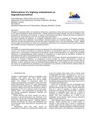
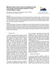
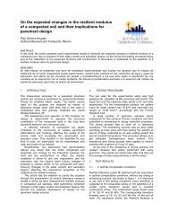
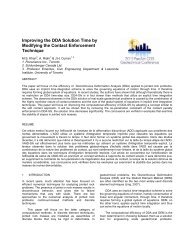
<str<strong>on</strong>g>Case</str<strong>on</strong>g> <str<strong>on</strong>g>histories</str<strong>on</strong>g> <strong>on</strong> <strong>the</strong> <strong>use</strong> <strong>of</strong> <strong>helical</strong> <strong>piles</strong> <strong>for</strong><br />
retr<strong>of</strong>itting <strong>and</strong> <strong>new</strong> c<strong>on</strong>structi<strong>on</strong><br />
Dino Vito, M.A.Sc., P.Eng. Tayler Cook, University <strong>of</strong> Waterloo<br />
EBS Engineering <strong>and</strong> C<strong>on</strong>structi<strong>on</strong> Limited, Breslau, Ontario, Canada<br />
ABSTRACT<br />
The applicati<strong>on</strong> <strong>of</strong> <strong>helical</strong> <strong>piles</strong> <strong>and</strong> anchors has exp<strong>and</strong>ed bey<strong>on</strong>d lightly loaded <strong>and</strong> temporary structures to include<br />
medium <strong>and</strong> heavily loaded permanent structures subjected to both compressi<strong>on</strong> <strong>and</strong> tensi<strong>on</strong>. Helical <strong>piles</strong> provide an<br />
increasingly viable opti<strong>on</strong> in many different situati<strong>on</strong>s <strong>and</strong> <strong>of</strong>fer benefits not available with more traditi<strong>on</strong>al foundati<strong>on</strong><br />
technologies. Several different instances where <strong>helical</strong> <strong>piles</strong> proved to be an effective soluti<strong>on</strong> to design challenges are<br />
examined <strong>and</strong> summarized.<br />
RÉSUMÉ<br />
Les applicati<strong>on</strong>s pour les pieux d’acier vrillé et d’ancres <strong>on</strong>t rép<strong>and</strong>u au-delà des structures temporaire à charge légère<br />
pour inclure, l’applicati<strong>on</strong>s de structures permanente a charge moyenne ou lourde et en compressi<strong>on</strong> ou en tensi<strong>on</strong>.<br />
Les pieux d’acier vrillé s<strong>on</strong> c<strong>on</strong>sideré de plus en plus, comme une opti<strong>on</strong> viable pour de nombre<strong>use</strong>s situati<strong>on</strong>s<br />
différentes et présente des bénéfices qui ne s<strong>on</strong>t pas disp<strong>on</strong>ible avec la technologie traditi<strong>on</strong>nelle de f<strong>on</strong>dati<strong>on</strong><br />
courante. Plusieurs cas différents ou les pieux d’acier vrillé <strong>on</strong> prouve à être une soluti<strong>on</strong> efficace pour des design qui<br />
présente des défis, s<strong>on</strong>t examiné et résumé.<br />
1 INTRODUCTION<br />
Helical <strong>piles</strong> <strong>and</strong> anchors have been <strong>use</strong>d to support<br />
boardwalks in envir<strong>on</strong>mentally sensitive areas, to support<br />
tower foundati<strong>on</strong>s (<strong>new</strong> <strong>and</strong> retr<strong>of</strong>it), to support <strong>and</strong> lift<br />
existing structures, to augment existing foundati<strong>on</strong>s, soil<br />
nailing applicati<strong>on</strong>s, heavily loaded <strong>piles</strong> in <strong>new</strong><br />
c<strong>on</strong>structi<strong>on</strong>, <strong>and</strong> retaining wall support <strong>and</strong> tiebacks<br />
(<strong>new</strong> <strong>and</strong> retr<strong>of</strong>it).<br />
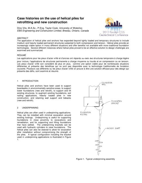
2 UNDERPINNING<br />
Helical <strong>piles</strong> are <strong>of</strong>ten <strong>use</strong>d in underpinning applicati<strong>on</strong>s.<br />
They can be installed with minimal excavati<strong>on</strong> around<br />
existing footings. Underpinning is <strong>use</strong>ful <strong>for</strong> supporting<br />
foundati<strong>on</strong>s in close proximity to excavati<strong>on</strong>s <strong>and</strong><br />
remediati<strong>on</strong>, <strong>and</strong> <strong>for</strong> supporting <strong>and</strong> lifting foundati<strong>on</strong>s<br />
that have settled. The underpinning brackets can be<br />
<strong>use</strong>d with hydraulic cylinders to raise foundati<strong>on</strong>s. The<br />
<strong>helical</strong> <strong>piles</strong> can also be sleeved to allow <strong>for</strong> excavati<strong>on</strong><br />
after installati<strong>on</strong> without compromising <strong>the</strong> strength <strong>of</strong><br />
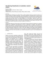
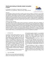
<strong>the</strong> <strong>piles</strong>. A typical c<strong>on</strong>figurati<strong>on</strong> including <strong>the</strong> bracket<br />
<strong>use</strong>d in underpinning applicati<strong>on</strong>s is illustrated in Figure<br />
1.<br />
Figure 1. Typical underpinning assembly
The bracket is generally bolted to <strong>the</strong> c<strong>on</strong>crete foundati<strong>on</strong><br />
using lag bolts. This can be modified to suit different<br />
situati<strong>on</strong>s including lumber <strong>and</strong> st<strong>on</strong>e foundati<strong>on</strong>s.<br />
2.1 Residential underpinning<br />
Three residences were underpinned using <strong>helical</strong> <strong>piles</strong>.<br />
The buildings were c<strong>on</strong>structed <strong>on</strong> structural fill, <strong>and</strong><br />
within three m<strong>on</strong>ths cracks were noticed. The movement<br />
was ca<strong>use</strong>d by a s<strong>of</strong>t fill z<strong>on</strong>e at <strong>the</strong> rear <strong>of</strong> <strong>the</strong><br />
residences, <strong>and</strong> it was determined that movement was<br />
occurring both horiz<strong>on</strong>tally <strong>and</strong> vertically. These issues<br />
needed to be fixed without displacing <strong>the</strong> residents <strong>of</strong> <strong>the</strong><br />
units.<br />
A total <strong>of</strong> 50 solid steel, square shaft <strong>helical</strong> <strong>piles</strong><br />
were utilized to stabilize <strong>the</strong> existing residential structure;<br />
45 installed to resist 445 kN kips in compressi<strong>on</strong>, <strong>and</strong> 5<br />
as tieback anchors to resist 356 kN in tensi<strong>on</strong>. The<br />
stabilizati<strong>on</strong> was completed quickly <strong>and</strong> effectively, <strong>and</strong><br />
<strong>the</strong> homeowners were not required to move out during<br />
c<strong>on</strong>structi<strong>on</strong>.<br />
2.2 11-Storey residential underpinning, Richm<strong>on</strong>d Hill,<br />
Ontario<br />
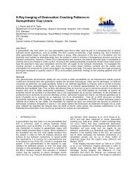
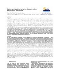
In 1998, an 11-storey c<strong>on</strong>dominium was underpinned<br />
using square shaft <strong>helical</strong> <strong>piles</strong>. Figure 2 is a photo <strong>of</strong><br />
<strong>the</strong> building.<br />
Figure 3. Heavy duty foundati<strong>on</strong> bracket assembly<br />
The bracket is significantly larger than that illustrated in<br />
Figure 2, <strong>and</strong> rated <strong>for</strong> ultimate loads up to 667 kN.<br />
2.3 13-Storey residential underpinning, Tor<strong>on</strong>to,<br />
Ontario<br />
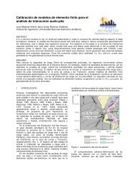
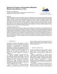
In 2003, a furnace oil tank leaked in <strong>the</strong> parking garage<br />
<strong>of</strong> a 13-storey apartment building in Tor<strong>on</strong>to, Ontario.<br />
The building is shown in Figure 4.<br />
Figure 2. Photograph <strong>of</strong> 11-storey residential building<br />
The parking garage foundati<strong>on</strong> walls, two columns <strong>and</strong><br />
four shear walls <strong>of</strong> <strong>the</strong> building were undermined by<br />
dewatering ef<strong>for</strong>ts due to an artesian aquifer. The limited<br />
space in <strong>the</strong> parking garage <strong>and</strong> <strong>the</strong> presence <strong>of</strong> <strong>the</strong><br />
aquifer meant more traditi<strong>on</strong>al support methods like<br />
driven <strong>piles</strong> or caiss<strong>on</strong>s were not viable.<br />
Eighty-three (83) 50.8-mm solid steel, square shaft<br />
<strong>helical</strong> <strong>piles</strong> with 152-mm diameter grout columns were<br />
<strong>use</strong>d to support this building. A compressive load test<br />
was completed <strong>on</strong> site, prior to installati<strong>on</strong>, <strong>and</strong> ultimate<br />
loads <strong>of</strong> 667 kN per <strong>helical</strong> pile were determined. These<br />
high loads required special, heavy duty foundati<strong>on</strong> repair<br />
brackets which are illustrated in Figure 3.
Figure 4. Photograph <strong>of</strong> 13-storey residential building<br />
After an investigati<strong>on</strong>, petroleum hydrocarb<strong>on</strong><br />
c<strong>on</strong>taminati<strong>on</strong> was found in soils underneath <strong>the</strong><br />
building, <strong>and</strong> immediate acti<strong>on</strong> was required. Multiple<br />
envir<strong>on</strong>mental remediati<strong>on</strong> techniques were c<strong>on</strong>sidered<br />
<strong>for</strong> this project, but in <strong>the</strong> end a remedial excavati<strong>on</strong><br />
where <strong>the</strong> soils could be removed safely <strong>and</strong> treated<br />
<strong>of</strong>fsite was deemed <strong>the</strong> most effective soluti<strong>on</strong> in this<br />
situati<strong>on</strong>. Traditi<strong>on</strong>al underpinning methods were<br />
c<strong>on</strong>sidered, but column loads in excess <strong>of</strong> 2669 kN <strong>and</strong><br />
limited head room in <strong>the</strong> parking garage made <strong>the</strong>se<br />
opti<strong>on</strong>s very expensive <strong>and</strong> time c<strong>on</strong>suming.<br />
Fifty-<strong>on</strong>e (51) 44.4-mm inch solid steel, square shaft<br />
<strong>helical</strong> <strong>piles</strong> were installed, complete with 4.9-m steel<br />
sleeves <strong>and</strong> a 127-mm diameter grout column. Figure 5<br />
is a drawing <strong>of</strong> <strong>the</strong> support <strong>of</strong> a column <strong>on</strong> this site.<br />
Figure 5. Underpinning <strong>and</strong> supporting during<br />
envir<strong>on</strong>mental excavati<strong>on</strong><br />
Column footings as well as foundati<strong>on</strong> walls were<br />
supported with <strong>the</strong> <strong>piles</strong> during excavati<strong>on</strong>. The<br />
excavati<strong>on</strong> was completed to a depth <strong>of</strong> 2.7-m below <strong>the</strong><br />
base <strong>of</strong> <strong>the</strong> footing, <strong>and</strong> <strong>the</strong> c<strong>on</strong>taminated soil was<br />
removed. This was completed with most <strong>of</strong> <strong>the</strong> parking<br />
garage remaining operati<strong>on</strong>al, <strong>and</strong> no residents were<br />
displaced. In order to minimize corrosi<strong>on</strong> <strong>on</strong> <strong>the</strong>se <strong>piles</strong>,<br />
<strong>the</strong> steel <strong>helical</strong> <strong>piles</strong> were hot-dipped galvanized. The<br />
grout column, as well as <strong>the</strong> steel sleeve, provide<br />
additi<strong>on</strong>al corrosi<strong>on</strong> protecti<strong>on</strong> <strong>for</strong> <strong>the</strong> pile.<br />
3 NEW CONSTRUCTION<br />
Helical <strong>piles</strong> have traditi<strong>on</strong>ally been c<strong>on</strong>sidered <strong>for</strong> light<br />
<strong>and</strong> medium loaded structures as well as in temporary<br />
applicati<strong>on</strong>s. Original c<strong>on</strong>cerns with this technology <strong>for</strong><br />
<strong>new</strong> c<strong>on</strong>structi<strong>on</strong> applicati<strong>on</strong>s included inefficiency due to<br />
load capabilities, <strong>and</strong> unacceptable deflecti<strong>on</strong> values.<br />
Load test data c<strong>on</strong>tinue to indicate large load capabilities<br />
<strong>for</strong> <strong>helical</strong> <strong>piles</strong> with low deflecti<strong>on</strong> values. As a result,
<strong>helical</strong> <strong>piles</strong> in <strong>new</strong> c<strong>on</strong>structi<strong>on</strong> applicati<strong>on</strong>s are<br />
becoming increasingly viable. Projects have been<br />
successfully completed using <strong>helical</strong> <strong>piles</strong> in residential,<br />
commercial, instituti<strong>on</strong>al, <strong>and</strong> small <strong>and</strong> large scale<br />
industrial applicati<strong>on</strong>s. Typical terminati<strong>on</strong>s <strong>for</strong> <strong>new</strong><br />
c<strong>on</strong>structi<strong>on</strong> projects are shown in Figure 6.<br />
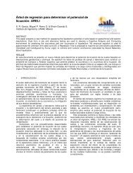
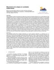
Figure 7. Completed mausoleum<br />
Space was limited <strong>and</strong> very valuable in <strong>the</strong> urban<br />
locati<strong>on</strong>, <strong>and</strong> c<strong>on</strong>structi<strong>on</strong> noise <strong>and</strong> vibrati<strong>on</strong>s were a<br />
major c<strong>on</strong>cern due to <strong>the</strong> close proximity <strong>of</strong> residential<br />
areas.<br />
The soils investigati<strong>on</strong> revealed a deep foundati<strong>on</strong><br />
was required beca<strong>use</strong> surface soils did not have <strong>the</strong><br />
strength <strong>for</strong> bearing <strong>the</strong> design loads <strong>on</strong> shallow<br />
foundati<strong>on</strong>s. Load tests <strong>on</strong> <strong>helical</strong> <strong>piles</strong> proved <strong>the</strong>y were<br />
capable <strong>of</strong> resisting design loads. Nearly 200 solid steel,<br />
square shaft <strong>helical</strong> <strong>piles</strong> were installed <strong>on</strong> site <strong>for</strong> four<br />
different projects. The versatility <strong>of</strong> <strong>the</strong> <strong>piles</strong> combined<br />
with no spoils or vibrati<strong>on</strong>s made <strong>the</strong>m <strong>the</strong> most efficient<br />
soluti<strong>on</strong> <strong>for</strong> many parts <strong>of</strong> this project.<br />
Figure 6. Typical <strong>new</strong> c<strong>on</strong>structi<strong>on</strong> bracket terminati<strong>on</strong><br />
The bracket c<strong>on</strong>sists <strong>of</strong> a solid steel plate, <strong>and</strong> a<br />
round steel sleeve that fits over <strong>the</strong> <strong>helical</strong> pile. In<br />
tensi<strong>on</strong> situati<strong>on</strong>s, this bracket is ei<strong>the</strong>r bolted to <strong>the</strong><br />
shaft, or a steel plate is <strong>use</strong>d instead <strong>and</strong> is welted to <strong>the</strong><br />
shaft.<br />
3.1 Mausoleum, Tor<strong>on</strong>to<br />
3.2 Tiebacks <strong>for</strong> shoring, L<strong>on</strong>d<strong>on</strong>, Ontario<br />
In 2007, an access manhole <strong>for</strong> a sanitary trunk sewer<br />
was installed in L<strong>on</strong>d<strong>on</strong>, Ontario. This required a deep<br />
excavati<strong>on</strong>, <strong>and</strong> shoring had to be installed to support <strong>the</strong><br />
surrounding soils. The site was in a <strong>for</strong>ested area al<strong>on</strong>g<br />
<strong>the</strong> side <strong>of</strong> a creek, so minimizing <strong>the</strong> envir<strong>on</strong>mental<br />
impacts was important. Figure 8 is a photograph <strong>of</strong> <strong>the</strong><br />
manhole after installati<strong>on</strong>.<br />
In 2008, a c<strong>on</strong>structi<strong>on</strong> project took place at a cemetery<br />
in Tor<strong>on</strong>to, Ontario. C<strong>on</strong>structi<strong>on</strong> involved large shoring<br />
walls, a pumping stati<strong>on</strong>, a mas<strong>on</strong>ry wall <strong>and</strong> a<br />
mausoleum. A photo <strong>of</strong> <strong>the</strong> completed mausoleum is<br />
shown in Figure 7.<br />
Figure 8. Fox Hollow sanitary trunk sewer manhole
A geotechnical investigati<strong>on</strong> revealed <strong>the</strong> underlying<br />
soil c<strong>on</strong>sisted <strong>of</strong> a layer <strong>of</strong> 1.5 m layer <strong>of</strong> topsoil with a<br />
large layer <strong>of</strong> compact silt underneath. Installati<strong>on</strong> <strong>of</strong><br />
<strong>helical</strong> <strong>piles</strong> as soil anchors to tie back steel sheet <strong>piles</strong><br />
was determined to be <strong>the</strong> most efficient method <strong>of</strong><br />
shoring. They were capable <strong>of</strong> being installed with<br />
minimal envir<strong>on</strong>mental effects <strong>and</strong> <strong>the</strong>y could resist<br />
design loads immediately. Thirty-three (33) 57.1-mm<br />
solid steel, square shaft <strong>helical</strong> anchors were installed<br />
<strong>and</strong> certified to resist working tensi<strong>on</strong> loads <strong>of</strong> 333 kN.<br />
The anchors were preloaded <strong>and</strong> terminated with<br />
threaded rod adapters.<br />
3.3 Hotel <strong>and</strong> c<strong>on</strong>venti<strong>on</strong> centre, Windsor, Ontario<br />
soil excavati<strong>on</strong> <strong>and</strong> installati<strong>on</strong> can be completed with<br />
portable equipment. This is a key factor when<br />
boardwalks are being installed in wetl<strong>and</strong>s or parks,<br />
where heavy machinery can have negative impacts <strong>on</strong><br />
<strong>the</strong> envir<strong>on</strong>ment <strong>and</strong> aes<strong>the</strong>tics <strong>of</strong> <strong>the</strong> site. In <strong>the</strong>se<br />
situati<strong>on</strong>s <strong>the</strong>y can easily be installed without a grout<br />
column, leaving <strong>the</strong> <strong>piles</strong> capable <strong>of</strong> fully supporting <strong>the</strong><br />
ultimate load immediately after installati<strong>on</strong>. This<br />
significantly reduces <strong>the</strong> durati<strong>on</strong> <strong>of</strong> <strong>the</strong> project, <strong>and</strong> also<br />
provides increased opportunities <strong>for</strong> installati<strong>on</strong> in<br />
situati<strong>on</strong>s that would normally not be feasible. Figure 10<br />
illustrates <strong>the</strong> typical pile terminati<strong>on</strong> <strong>for</strong> boardwalk <strong>and</strong><br />
pedestrian bridge walkways.<br />
In 2007, a large c<strong>on</strong>structi<strong>on</strong> project including a fivestorey<br />
underground parking garage in Windsor, Ontario<br />
was completed. The water table <strong>on</strong> <strong>the</strong> site was very<br />
high due to <strong>the</strong> close proximity <strong>of</strong> <strong>the</strong> Detroit River,<br />
subjecting <strong>the</strong> foundati<strong>on</strong> to significant buoyancy <strong>for</strong>ces.<br />
These <strong>for</strong>ces meant <strong>the</strong> raft slab had to be tied down to<br />
adequate load-bearing soil below <strong>the</strong> bottom <strong>of</strong> <strong>the</strong> slab.<br />
Figure 9 is a photo <strong>of</strong> <strong>the</strong> project during c<strong>on</strong>structi<strong>on</strong>.<br />
Figure 10. Boardwalk bracket terminati<strong>on</strong><br />
These brackets are designed <strong>for</strong> compressi<strong>on</strong> loads <strong>on</strong>ly<br />
<strong>and</strong> are ideal <strong>for</strong> attaching pressure treated lumber or<br />
o<strong>the</strong>r c<strong>on</strong>structi<strong>on</strong> materials.<br />
4.1 Boardwalk, Waterloo<br />
Figure 9. Project during c<strong>on</strong>structi<strong>on</strong><br />
In 2000, a boardwalk was built using <strong>helical</strong> <strong>piles</strong> as<br />
support in Waterloo, Ontario. The 3-m wide boardwalk<br />
was built around Silver Lake, as part <strong>of</strong> <strong>the</strong> park’s trail<br />
network <strong>and</strong> supports multiple benches <strong>and</strong> gazebos.<br />
Figure 11 is a photo <strong>of</strong> a boardwalk supported using<br />
<strong>helical</strong> <strong>piles</strong>.<br />
Tensi<strong>on</strong> tests showed <strong>helical</strong> <strong>piles</strong> installed to<br />
approximately 21.3 m below <strong>the</strong> base <strong>of</strong> <strong>the</strong> slab were<br />
capable <strong>of</strong> resisting required loads. Helical <strong>piles</strong> proved<br />
to be <strong>the</strong> most viable soluti<strong>on</strong> in this situati<strong>on</strong>, <strong>and</strong> 259<br />
<strong>helical</strong> anchors were <strong>use</strong>d <strong>on</strong> this project. 57.1-mm solid<br />
steel, square shaft <strong>helical</strong> <strong>piles</strong> complete with a 152-mm<br />
diameter grout column were <strong>use</strong>d to resist ultimate<br />
tensi<strong>on</strong> loads between 444 <strong>and</strong> 734 kN. The <strong>piles</strong> were<br />
preloaded <strong>and</strong> terminated with custom designed brackets<br />
that were able to be installed after <strong>the</strong> raft slab was<br />
poured.<br />
4 BOARDWALKS, WALKWAYS AND PEDESTRIAN<br />
BRIDGES<br />
The <strong>use</strong> <strong>of</strong> <strong>helical</strong> <strong>piles</strong> to support boardwalks, walkways<br />
<strong>and</strong> pedestrian bridges is becoming increasingly popular.<br />
Helical <strong>piles</strong> are <strong>of</strong>ten <strong>the</strong> most effective system <strong>for</strong> this<br />
applicati<strong>on</strong> <strong>for</strong> many reas<strong>on</strong>s. Helical <strong>piles</strong> require no<br />
Figure 11. Boardwalk supported using <strong>helical</strong> <strong>piles</strong><br />
Based <strong>on</strong> <strong>the</strong> soil <strong>and</strong> site c<strong>on</strong>diti<strong>on</strong>s, required loads, <strong>and</strong><br />
project type, <strong>helical</strong> <strong>piles</strong> were recommended as <strong>the</strong> most<br />
efficient method <strong>of</strong> supporting this project.
A series <strong>of</strong> 117 <strong>helical</strong> <strong>piles</strong> were installed to a depth<br />
<strong>of</strong> 3.65 m below grade. 12 <strong>of</strong> <strong>the</strong>se were 88.9 mm<br />
round, hollow steel shaft <strong>helical</strong> <strong>piles</strong>, with a 203, 254,<br />
<strong>and</strong> 305-mm triple <strong>helical</strong> c<strong>on</strong>figurati<strong>on</strong>. These <strong>piles</strong><br />
were installed to resist compressi<strong>on</strong> working loads<br />
between 78 <strong>and</strong> 201 kN, as specified by <strong>the</strong> design<br />
engineer. The remainder <strong>of</strong> <strong>the</strong> <strong>piles</strong> installed were 38.1-<br />
mm solid steel, square shaft <strong>piles</strong> with a double <strong>helical</strong><br />
c<strong>on</strong>figurati<strong>on</strong> <strong>of</strong> 203 <strong>and</strong> 254-mm diameter helices.<br />
These <strong>piles</strong> were installed to resist compressi<strong>on</strong> working<br />
loads between 44 <strong>and</strong> 122 kN, as specified by <strong>the</strong> design<br />
engineer.<br />
or spoils, <strong>the</strong> potential <strong>for</strong> installati<strong>on</strong> without heavy<br />
machinery, <strong>and</strong> <strong>the</strong> load capabilities that were previously<br />
not c<strong>on</strong>sidered with this system, present efficient<br />
foundati<strong>on</strong> soluti<strong>on</strong>s <strong>for</strong> countless c<strong>on</strong>structi<strong>on</strong> projects.<br />
ACKNOWLEDGEMENTS<br />
The writers would like to acknowledge <strong>the</strong> c<strong>on</strong>tributi<strong>on</strong> <strong>of</strong><br />
Mr. J. Heinisch, P.Eng., <strong>for</strong> his assistance in writing this<br />
paper.<br />
5 LATERAL LOADING<br />
Helical <strong>piles</strong> are an effective method <strong>of</strong> resisting lateral<br />
loading in many different applicati<strong>on</strong>s. They can be<br />
installed <strong>on</strong> an incline/batter as required with no added<br />
installati<strong>on</strong> equipment or difficulty.<br />
5.1 Billboard support, Tor<strong>on</strong>to, Ontario<br />
In 1999, seventy-eight (78) 44.5-mm solid steel, square<br />
shaft <strong>helical</strong> anchors with a 254, 305, 356-mm triple<br />
<strong>helical</strong> c<strong>on</strong>figurati<strong>on</strong> were installed to support a series <strong>of</strong><br />
billboards as seen in Figure 12.<br />
Figure 12. Billboards supported using <strong>helical</strong> <strong>piles</strong><br />
The billboards were located at <strong>the</strong> edge <strong>of</strong> an enclosure<br />
<strong>for</strong> a trans<strong>for</strong>mer stati<strong>on</strong>. The compressi<strong>on</strong> loads <strong>of</strong> <strong>the</strong><br />
billboards was minimal, however, wind loadings resulted<br />
in high lateral <strong>and</strong> over-turning moments. Helical <strong>piles</strong><br />
were <strong>use</strong>d beca<strong>use</strong> installati<strong>on</strong> could be completed in<br />
close proximity to <strong>the</strong> trans<strong>for</strong>mers, <strong>and</strong> <strong>the</strong> lateral<br />
loading could be resisted by installing <strong>the</strong>m <strong>on</strong> 10° to 15°<br />
batters. Each pile was certified to resist an ultimate load<br />
<strong>of</strong> 400 kN.<br />
6 CONCLUSIONS<br />
As <strong>the</strong> number <strong>of</strong> projects successfully completed using<br />
<strong>helical</strong> <strong>piles</strong> increases, <strong>the</strong> level <strong>of</strong> familiarity <strong>and</strong><br />
c<strong>on</strong>fidence also increases. Load test results c<strong>on</strong>tinue to<br />
prove <strong>helical</strong> <strong>piles</strong> effective at resisting tensi<strong>on</strong> <strong>and</strong><br />
compressi<strong>on</strong> loads, making <strong>helical</strong> <strong>piles</strong> an opti<strong>on</strong> <strong>for</strong><br />
many different foundati<strong>on</strong> designs. The many<br />
advantages <strong>of</strong> using <strong>helical</strong> <strong>piles</strong>, including no vibrati<strong>on</strong>