Design Recommendation for Stone Column Reinforced Soft Clay ...
Design Recommendation for Stone Column Reinforced Soft Clay ...
Design Recommendation for Stone Column Reinforced Soft Clay ...

Create successful ePaper yourself
Turn your PDF publications into a flip-book with our unique Google optimized e-Paper software.
phenomenon is duly supported by other researchers (Low<br />
et al., 1994, Abusharar et al., 2009 and Deb, 2010).<br />
As reported by Han et al. (2002), a smear zone is<br />
developed in the soil adjacent to the soil-column interface<br />
due to installation. Also, because of the migration of clay<br />
particles from soil into the pores of the column, a clogged<br />
zone may be <strong>for</strong>med within the column in the vicinity of<br />
the soil-column interface (Adalier et al., 2004).<br />
Based on „free strain‟ hypothesis and considering the<br />
arching, smear and the clogging effects, a numerical<br />
model (finite difference method) have already been<br />
developed and validated by the authors (Indraratna et al.,<br />
2010). Using the model, a design methodology<br />
associated with appropriate design curves has been<br />
proposed and a typical design example has been<br />
illustrated in this paper.<br />
H e<br />
Embankment<br />
the corresponding time, and thereby compute the other<br />
time-dependant variables such as the degree of<br />
Impervious rigid boundary (a) <strong>Stone</strong> column<br />
Unit cell idealization q = Q + γ e H e<br />
r<br />
H<br />
Unit cell<br />
Un (b)<br />
Z<br />
it<br />
cel (<br />
2 NUMERICAL ANALYSIS<br />
l<br />
Undisturbed<br />
b<br />
zone<br />
The details of the numerical model developed have been<br />
)<br />
described elsewhere (Indraratna et al., 2010). A brief<br />
Smear zone<br />
illustration of the analysis carried out is given herein.<br />
Clogged<br />
The analysis was done based on the assumption that<br />
r s<br />
column zone<br />
the compressive strains of the soil column occur only in<br />
the vertical direction, and ignoring the elastic settlements<br />
r e<br />
Unclogged<br />
which are insignificant compared to the consolidation<br />
column zone<br />
settlement. The soil was assumed to be fully saturated<br />
with incompressible water, the flow of water through the<br />
soil to be purely horizontal (radial towards the column)<br />
following Darcy‟s law and no flow of water to take place<br />
(c)<br />
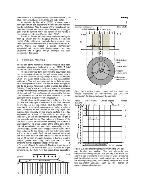
through the cylindrical boundary and the impervious base Fig.1. (a) A typical stone column rein<strong>for</strong>ced soft clay<br />
of the unit cell. The coefficients of permeability (k h) and deposit supporting an embankment. (b) Unit cell<br />
compressibility (m v) of the soil was assumed to remain idealization. (c) Cross section of the unit cell.<br />
constant during the process of consolidation.<br />
The idealised problem is depicted in Figures 1(a) and Radial<br />
(b). The soft clay layer of thickness H has been assumed divisions:<br />
<strong>Stone</strong> column Ground surface Vertical<br />
to overlay on an impervious rigid boundary, and is<br />
improved by a group of stone columns having a radius r c<br />
divisions: 1<br />
δ z<br />
2 3 . . . . . . . . . i . . . . . . . . . n-1 n 1<br />
each, extended to the bottom of the clay layer. The<br />
2<br />
average load intensity on the ground surface ( q ), was<br />
δ z<br />
expressed as a sum of the uni<strong>for</strong>m surcharge load<br />
intensity Q on the embankment fill and the self weight of<br />
3<br />
δ r δ r<br />
.<br />
the embankment (γ eH e). The radius of influence of the<br />
.<br />
unit cell r e could be calculated following the method of<br />
δ z<br />
.<br />
Wang (2009). The cross section of the entire zone of the<br />
.<br />
unit cell was divided into four distinct zones (Fig.1c), viz.,<br />
j<br />
the unclogged column zone, clogged column zone, smear<br />
.<br />
zone adjacent to the column and the outer undisturbed<br />
.<br />
soil zone. As shown in Fig.2, the soil mass within the unit<br />
.<br />
cell had been divided both radially as well as vertically<br />
into (n-1) number of equal divisions; n being a positive<br />
.<br />
n-1<br />
integer greater than unity, such that each of such<br />
divisions may be expressed respectively as:<br />
δ r<br />
Impervious rigid boundary<br />
= (r e – r c)/(n-1) and δ z = H/(n-1). The total time interval of<br />
r e - r c<br />
n<br />
computation t t is divided into (n-1) number of equal<br />
Figure 2. Soil element discritization within the unit cell.<br />
divisions, i.e., δ t = t t /(n-1). In this paper, these separators<br />
are denoted as „nodes‟. The soil elements are<br />
blanket<br />
Q<br />
Sand<br />
understandably ring-shaped. The primary objective of the<br />
analysis was to compute the excess pore water pressures<br />
and the effective stresses developed at each separator at<br />
consolidation and settlement.<br />
Embank<br />
ment<br />
H