MX883 Manual - Australian Monitor
MX883 Manual - Australian Monitor
MX883 Manual - Australian Monitor

You also want an ePaper? Increase the reach of your titles
YUMPU automatically turns print PDFs into web optimized ePapers that Google loves.
<strong>MX883</strong><br />
8 CHANNEL STEREO MIC/LINE MIXER<br />
INSTALLATION AND OPERATION MANUAL
IMPORTANT SAFETY INFORMATION<br />
1. Save the carton and packing material even if the equipment has<br />
arrived in good condition. Should you ever need to ship the unit, use<br />
only the original factory packing.<br />
2. Read all documentation before operating your equipment. Retain<br />
all documentation for future reference.<br />
3. Follow all instructions printed on unit chassis for proper operation.<br />
4. Do not spill water or other liquids into or on the unit, or operate<br />
the unit while standing in liquid.<br />
5. Make sure power outlets conform to the power requirements listed<br />
on the back of the unit.<br />
6. Do not use the unit if the electrical power cord is frayed or broken.<br />
The power supply cords should be routed so that they are not likely<br />
to be walked on or pinched by items placed upon or against them,<br />
paying particular attention to cords and plugs, convenience<br />
receptacles, and the point where they exit from the appliance.<br />
7. Always operate the unit with the AC ground wire connected to the<br />
electrical system ground. Precautions should be taken so that the<br />
means of grounding of a piece of equipment is not defeated.<br />
8. Mains voltage must be correct and the same as that printed on the<br />
rear of the unit. Damage caused by connection to improper AC voltage<br />
is not covered by any warranty.<br />
9. Have gain controls on amplifi ers turned down during power-up<br />
to prevent speaker damage if there are high signal levels at the inputs.<br />
10 Power down & disconnect units from mains voltage before making<br />
connections.<br />
11. Never hold a power switch in the “ON” position if it won’t stay<br />
there itself!<br />
12. Do not use the unit near stoves, heat registers, radiators, or other heat<br />
producing devices.<br />
13. Do not block fan intake or exhaust ports. Do not operate equipment<br />
on a surface or in an environment which may impede the normal flow<br />
of air around the unit, such as a bed, rug, weathersheet, carpet,<br />
or completely enclosed rack. If the unit is used in an extremely dusty<br />
or smoky environment, the unit should be periodically “blown free”<br />
of foreign matter.<br />
14. Do not remove the cover. Removing the cover will expose you<br />
to potentially dangerous voltages. There are no user serviceable<br />
parts inside.<br />
15. Do not drive the inputs with a signal level greater than that required<br />
to drive equipment to full output.<br />
16. Do not connect the inputs / outputs of amplifi ers or consoles to any<br />
other voltage source, such as a battery, mains source, or power supply,<br />
regardless of whether the amplifi er or console is turned on or off.<br />
17. Do not run the output of any amplifi er channel back into another<br />
channel’s input. Do not parallel- or series-connect an amplifier output<br />
with any other amplifi er output. <strong>Australian</strong> <strong>Monitor</strong> Inc is not<br />
responsible for damage to loudspeakers for any reason.<br />
18. Do not ground any red (“hot”) terminal. Never connect a “hot” (red)<br />
output to ground or to another “hot” (red) output!<br />
19. Non-use periods. The power cord of equipment should be unplugged<br />
from the outlet when left unused for a long period of time.<br />
20. Service Information Equipment should be serviced by qualified service<br />
personnel when:<br />
A. The power supply cord or the plug has been damaged.<br />
B. Objects have fallen, or liquid has been spilled into the equipment<br />
C. The equipment has been exposed to rain<br />
D. The equipment does not appear to operate normally, or exhibits a marked<br />
change in performance<br />
E. The equipment has been dropped, or the enclosure damaged.<br />
THIS SAFETY INFORMATION IS OF A GENERAL NATURE AND MAY BE SUPERSEDED BY INSTRUCTIONS CONTAINED WITHIN THIS MANUAL
INTRODUCTION AND CONTENTS<br />
The <strong>MX883</strong> is a stereo 8 channel audio mixer that operates from<br />
110/230-240 VAC @ 50/60 Hz. The <strong>MX883</strong> offers high quality audio<br />
performance & a wide array of features in a standard 2 RU size.<br />
For table mounting, rubber feet are supplied but these can be removed<br />
if rack mounting is intended. There are eight dual purpose inputs<br />
consisting of balanced XLR inputs switchable between mic & line level<br />
and stereo RCA line level inputs. Each channel also features a line<br />
level direct output which can be used to feed additional amplifiers,<br />
mixers or recording devices. An internal jumper allows each input to be<br />
routed to the direct output either pre or post fader. Each input has front<br />
panel trim control, status LED and bass & treble controls. Each input<br />
channel can be routed to the left, right or aux output. The left and right<br />
outputs have a constant Q 5 band graphic EQ stage. Priority muting is<br />
available as an optional addition as is remote VCA master control and<br />
tone generation.<br />
The <strong>MX883</strong> also features 4 segment LED output metering & the ability<br />
to internally switch input 1 to be either pre or post master. With both<br />
Headphone out & Record out also available the <strong>MX883</strong> is extremely<br />
versatile. The <strong>MX883</strong> has taken the AMIS heritage of contractor<br />
friendly installation product & has added the audio fi delity needed in<br />
today’s AV contracting market.<br />
INTRODUCTION 3<br />
FRONT PANEL 4<br />
REAR PANEL 5<br />
INTERNAL ADJUSTMENTS 6<br />
INSTALLATION & TROUBLESHOOTING 7<br />
BASIC SETUP AND OPERATION 8<br />
DIMENSIONS 9<br />
BLOCK DIAGRAM 10<br />
SPECIFICATIONS 11<br />
AUS, EUR, USA<br />
Copyright 9th Feb 2006<br />
Rev A 13/02/07<br />
Rev B 19/03/08<br />
CAUTION<br />
RISK OF ELECTRIC SHOCK<br />
DO NOT OPEN<br />
This symbol is intended to alert the user to the presence<br />
of uninsulated “dangerous voltage” within the products<br />
enclosure that may be of suffi cient magnitude to constitute<br />
a risk of electric shock to persons.<br />
CAUTION: TO REDUCE THE RISK OF ELECTRIC SHOCK,<br />
DO NOT REMOVE COVER (OR BACK),<br />
NO USER SERVICEABLE PARTS INSIDE,<br />
REFER SERVICING TO QUALIFIED SERVICE PERSONAL.<br />
This symbol is intended to alert the user to the presence<br />
of important operational and maintenance (servicing)<br />
instructions in the literature accompanying the appliance.<br />
WARNING!<br />
TO REDUCE THE RISK OF FIRE OR ELECTRIC HOCK<br />
DO NOT EXPOSE THIS EQUIPMENT TO RAIN OR MOISTURE.<br />
Caution:<br />
To prevent electric shock do not use this (polarised) plug<br />
with an extension cord, receptacle or other outlet unless<br />
the blades can be fully inserted to prevent blade exposure.<br />
To prevent electric shock, match wide blade of plug to wide<br />
slot, fully insert.<br />
<strong>MX883</strong> INSTALLATION & OPERATION MANUAL<br />
PAGE 3
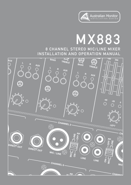
FRONT PANEL<br />
4<br />
18<br />
7 10<br />
5<br />
1<br />
2<br />
3 6<br />
9<br />
11<br />
1<br />
GAIN TRIM<br />
6<br />
LEFT, RIGHT AND AUX MASTER<br />
This control is used to adjust the input gain and affects both the XLR and<br />
the RCA inputs. The input gain can be adjusted by +/- 15dB. This allows<br />
a wide rage of program sources to be set up with optimum gain structure.<br />
With the gain trim in the centre position, the boost/cut is set to 0dB. See<br />
the block diagram on page 10 for details of the gain structure.<br />
2 LEVEL<br />
These pots control the overall mixed output level for the left, right and aux<br />
channels respectively.<br />
7 LEFT, RIGHT AND AUX VU DISPLAY<br />
These VU displays indicate output level for the left, right and aux<br />
channels respectively.<br />
Controls the level of the input signal.<br />
8<br />
LEFT AND RIGHT GRAPHIC EQ<br />
3 INPUT STATUS LEDS<br />
Each input has an LED status indicator. The LED is green when there is<br />
signal present and red if the signal is approaching clip. If the LED begins<br />
to light red this would indicate the internal signal level is 6dB before clip.<br />
Note that the front panel level control is post status LED and as such, the<br />
status LED is NOT affected by the level control. If an input channel is clipping<br />
use the gain control to adjust the correct amount of input level.<br />
4 CHANNEL TONE CONTROLS<br />
Each input has a 2 band EQ.<br />
Bass – +/-12dB 100Hz shelving<br />
Treble – +/-9dB 10kHz shelving<br />
These 5 band EQ sections are constant Q fi lters with centers at 100Hz,<br />
300Hz, 1kHz, 3kHz and 10kHz. Each fi lter has a range of 12dB cut and boost.<br />
9 HEADPHONE<br />
This 1/4” jack socket allows headphones to be used for monitoring. It can<br />
be set as pre or post master volume control. It can also be set to listen to<br />
the aux output, pre or post aux fader. See “Internal Settings” on page 6.<br />
Default factory setting is pre master volume control.<br />
10 POWER SWITCH<br />
This switch switches power from the mains. The up position is on.<br />
11 POWER ON LED<br />
5<br />
BUS SELECT SWITCHES<br />
This indicates there is power to the unit.<br />
These switches connect each input to the left, right or aux outputs. The<br />
LED above the switch indicates when the channel is being routed to the<br />
respective output.<br />
For stereo inputs the left signal only is routed to the left bus, the right<br />
signal only is routed to the right bus, and a mono summed signal is sent to<br />
the aux bus.<br />
PAGE 4<br />
<strong>MX883</strong> INSTALLATION & OPERATION MANUAL
REAR PANEL<br />
9 10<br />
7 8<br />
5<br />
6<br />
4<br />
3<br />
2<br />
1<br />
1<br />
CHANNEL INPUTS<br />
Each channel has two inputs:<br />
XLR input - This is a balanced input. It accepts mic or line level signals<br />
depending on the adjacent gain switch position. The XLR will also have<br />
+15V phantom power if selected on the adjacent switch.<br />
RCA input - This is an unbalanced line level input. The two RCA sockets are<br />
stereo, left and right.<br />
2<br />
P/P – PHANTOM POWER<br />
15V phantom power is available for condenser or electret microphones on<br />
the XLR input when this switch is in the “ON” position.<br />
3<br />
MIC / LINE<br />
These two switches control the sensitivity of the XLR input. In the “MIC”<br />
position the XLR input is suitable for use with microphones; in the “LINE”<br />
position the XLR input is suitable for use with a balanced line level signal.<br />
NOTE: Both MIC/LINE switches must be in the same<br />
position for correct operation of the balanced input.<br />
NOTE: The MIC/LINE switches only affect the XLR input.<br />
6<br />
LEFT, RIGHT AND AUX OUTPUT<br />
The OUTPUT XLR’s provides balanced line level signal of the left, right and<br />
aux channels respectively.<br />
NOTE: When wiring the LINE output as unbalanced, Pin2<br />
should be wired as hot and Pin1 should be wired as ground/shield.<br />
Do not wire Pin3.<br />
7<br />
LINK BUS<br />
This connector is used for linking two <strong>MX883</strong>’s together. A short cable<br />
(
INTERNAL ADJUSTMENTS<br />
2 5<br />
5<br />
5<br />
1<br />
4<br />
3<br />
1<br />
CHANNEL DIRECT OUT PRE/POST FADER<br />
4<br />
HEADPHONE ROUTING<br />
The pre or post assignment of the direct output is set via this jumper. This<br />
is used to make the Direct Outputs either pre or post channel fader volume.<br />
Set to the Channel 1 side the Direct Output is post fader (i.e. the channel<br />
fader volume affects the Direct Output). Set to the Channel 8 side the Direct<br />
Output is pre fader. The default factory setting is pre fader.<br />
2 CHANNEL 1 AND 2 HPF<br />
Channels 1 and 2 have a 120Hz 24dB/octave high pass fi lter to remove<br />
handling noise and floor rumble. The fi lter is active by default. The jumpers<br />
are located at the back of the unit on the upper board near channels 1 and<br />
2. Move the jumper toward channel 8 to bypass the fi lter.<br />
3 CHANNEL 1 ROUTING<br />
If channel 1 is being used as a priority input it can be routed so that the<br />
master volume does not affect channel 1. The default factory setting is pre<br />
master fader meaning the master volume affects channel 1 in the mix. The<br />
switch is located near the master pots. Move the switch toward channel 1<br />
to set channel 1 to post master fader.<br />
The headphone level can be routed so that it is affected by the master<br />
volume. The default factory setting is pre master fader meaning the master<br />
volume does not affect the headphone volume. The switch is located just<br />
behind the front panel near the master pot. Move the switch toward the<br />
front to set the headphone to post master fader. The headphone can also<br />
listen to the aux output. The headphone source switch is below the pre/<br />
post switch. Move the switch toward the front to set it to aux. When set to<br />
aux the headphone is always post fader.<br />
5 OPTIONAL MODULES<br />
The <strong>MX883</strong> can have installed:<br />
- 2 VCA modules for left and right outputs<br />
- Tone Generator module<br />
- 2 Priority Muting modules for left and right outputs<br />
See your local <strong>Australian</strong> <strong>Monitor</strong> dealer for more information.<br />
PAGE 6<br />
<strong>MX883</strong> INSTALLATION & OPERATION MANUAL
INSTALLATION AND TROUBLESHOOTING<br />
INPUT CONNECTIONS<br />
For wiring balanced in, pin 2 is hot. Unbalanced wiring on the microphone<br />
inputs is not recommended. Balanced input wiring (shielded pair cable) is<br />
recommended.<br />
Unbalanced RCA wiring should be keep as short as possible. Typically less<br />
than 3m.<br />
LINE OUTPUT<br />
The LINE output XLR can be used to connect up to 6 booster amplifi ers.<br />
Balanced wiring (shielded pair cable) is recommended.<br />
NOTE: When wiring the LINE output as unbalanced, Pin2 should<br />
be wired as hot and Pin1 should be wired as ground/shield.<br />
Do not wire Pin3.<br />
RECORD OUTPUT<br />
The Record output wiring should be kept as short as possible. Typically less<br />
than 3m.<br />
DIRECT OUTPUT<br />
The direct outputs are balance and should be wired tip hot. When wiring the<br />
direct outputs as unbalanced or when using a mono jack the ring and sleeve<br />
should be connected together and to the shield.<br />
TROUBLESHOOTING GUIDE<br />
TROUBLE LIKELY CAUSE REMEDY<br />
Power LED not on Power not reaching unit Check mains connection<br />
Check mains fuse<br />
Check power switch is on<br />
Noisy output Incorrect gain structure See setup guide<br />
Distorted sound Input is overloaded Check MIC/LINE switch<br />
Reduce input level at source<br />
Output is being over driven<br />
Bass control is turned up<br />
Reduce output volume<br />
Reduce Bass control level<br />
No sound but unit is on Volume turned down Check volume controls<br />
Tones and/or VCA control does not work Module not installed Purchase optional modules<br />
Condenser microphone does not work Phantom power not switched on Switch on phantom power<br />
<strong>MX883</strong> INSTALLATION & OPERATION MANUAL<br />
PAGE 7
BASIC SETUP AND OPERATION<br />
The inputs of the <strong>MX883</strong> can accommodate a wide range of sources<br />
including dynamic microphones, DVD and CD players. The output may be<br />
used to drive power (booster) amplifi ers, other mixers or mixer amplifi ers.<br />
Each installation will require setting the appropriate relative mix of levels<br />
between microphones and program. Also consider what the output is<br />
driving.<br />
Setting up correct gain structure through the whole system is important<br />
to achieve optimal results. The following step by step procedure has been<br />
devised to assist during the setup process. When the <strong>MX883</strong> was shipped<br />
to you from the factory, it was set up in a particular way. In the following<br />
procedure it is essential that you are starting from these initial settings.<br />
+ Program Input Gain Controls – half (12 o’clock)<br />
+ XLR Mic/Line switch – MIC<br />
+ XLR Phantom power - on<br />
+ Input Level Controls – off<br />
+ Output Level Control – off<br />
CONNECT THE OUTPUTS<br />
Turn the amplifi ers off. Connect the <strong>MX883</strong> output to the amplifiers’ line<br />
level input. Check that the <strong>MX883</strong> is on, and then turn on the amplifiers.<br />
If the amplifi ers have a level control, set them it to a sensitivity of 0dBu.<br />
If in doubt, set it to maximum.<br />
SET THE LEVELS<br />
Turn the input levels up to 5. Turn up the output level until it is at an<br />
appropriate level for the listening environment. You will now have to adjust<br />
the relative levels of the inputs to achieve a good balance. The aim of these<br />
adjustments is to have all level controls at between 3 and 7. This may<br />
not be possible however. A good rule of thumb is that input level controls<br />
should be higher than the output level controls.<br />
CONNECT THE SOURCES<br />
First connect all the required sources to the appropriate input connectors.<br />
If the source is a microphone, set the MIC/LINE switches to the “MIC”<br />
position. If the source is an electret or condenser microphone, set the<br />
phantom switch to the “P/P on” position.<br />
PAGE 8<br />
<strong>MX883</strong> INSTALLATION & OPERATION MANUAL
DIMENSIONS<br />
<strong>MX883</strong> INSTALLATION & OPERATION MANUAL<br />
PAGE 9
BLOCK DIAGRAM<br />
PAGE 10<br />
<strong>MX883</strong> INSTALLATION & OPERATION MANUAL
SPECIFICATIONS<br />
FREQUENCY RESPONSE<br />
TOTAL HARMONIC DISTORTION<br />
SIGNAL TO NOISE RATIO<br />
CROSSTALK<br />
20Hz - 20kHz (+0,-3dB)<br />
< 0.1% @ 1kHz<br />
> 90dB (all pots at centre position)<br />
>70dB<br />
TONE CONTROLS BASS @ 100HZ +/- 12dB<br />
TREBLE @ 10KHZ<br />
+/- 9dB<br />
SENSITIVITY (TRIM IN CENTRE 0dB)<br />
MAX LEVEL IN<br />
MAX LEVEL OUT<br />
PHANTOM POWER<br />
Mic Sens 4.36mV, -45dBu Imp 1k3ohm<br />
Line Sens 0.775V, 0dBu Imp >100k<br />
RCA 200mV, -12dBu Imp 30kohm<br />
XLR mic -9dBu<br />
XLR line >30dBu<br />
RCA >30dBu<br />
+21dBu<br />
15V DC<br />
OUTPUTS MASTER OUT Nominal Level 0dBu into 1kohm<br />
Imp 100ohm<br />
MONO HEADPHONE OUT<br />
Nom -6dB into 200ohm<br />
Imp 10ohm<br />
MONO REC OUT<br />
Nom -12dB into 10kohm<br />
Imp 10kohm<br />
CHANNEL DIRECT OUT<br />
Nom 0dB into 1kohm<br />
Imp 100 ohm<br />
POWER INPUT<br />
POWER CONSUMPTION (MAX)<br />
AC: 230V/50Hz or 115V/60Hz, 3 pin IEC320-C14 connector<br />
30 VA<br />
FUSES MAINS (115V) 200mA<br />
MAINS (230V)<br />
100mA<br />
DIMENSIONS H X W X D<br />
SHIPPING DIMENSIONS<br />
WEIGHT<br />
88mm x 482mm x 270mm (3.5“x19”x10.6”)<br />
170mm x 505mm x 350mm (6.7“x19.9”x13.8”)<br />
Net 4.0kg (8.8lb)<br />
Shipping 4.5kg (9.9lb)<br />
<strong>MX883</strong> INSTALLATION & OPERATION MANUAL<br />
PAGE 11
AUSTRALIA AND NEW ZEALAND<br />
www.australianmonitor.com.au<br />
SYDNEY<br />
MELBOURNE<br />
BRISBANE<br />
ADELAIDE<br />
PERTH<br />
AUCKLAND<br />
(NSW & ACT SALES)<br />
(VIC & TAS SALES)<br />
(QLD SALES)<br />
(SA & NT SALES)<br />
(WA SALES)<br />
(NZ SALES)<br />
1 Clyde Street<br />
Silverwater<br />
NSW 2128<br />
Private Bag 149<br />
Silverwater NSW 1811<br />
Phone: (02) 9647 1411<br />
Fax: (02) 9648 3698<br />
Email:<br />
nsw@audiotelex.com.au<br />
22/277<br />
Middleborough Road<br />
Box Hill VIC 3128<br />
PO Box 151 Blackburn<br />
South VIC 3130<br />
Phone: (03) 9890 7477<br />
Fax: (03) 9890 7977<br />
Email:<br />
vic@audiotelex.com.au<br />
42 Commercial Road<br />
Fortitude Valley<br />
QLD 4006<br />
PO Box 2578 Fortitude<br />
Valley BC QLD 4006<br />
Phone: (07) 3852 1312<br />
Fax: (07) 3252 1237<br />
Email:<br />
qld@audiotelex.com.au<br />
31 Walsh Street<br />
Thebarton<br />
SA 5031<br />
PO Box 157<br />
Hindmarsh SA 5007<br />
Phone: (08) 8352 4444<br />
Fax: (08) 8352 4488<br />
Email:<br />
sa@audiotelex.com.au<br />
3/11 Howe Street<br />
Osborne Park WA 6017<br />
PO Box 1281<br />
Osborne Park BC<br />
WA 6916<br />
Phone: (08) 9204 0200<br />
Fax: (08) 9244 3783<br />
Email:<br />
wa@audiotelex.com.au<br />
9C Piermark Drive<br />
Albany 0752<br />
New Zealand<br />
PO Box 300-512<br />
Albany 0752<br />
Phone: (09) 415 9426<br />
Fax: (09) 415 9864<br />
Email:<br />
sales@audiotelex.co.nz<br />
EUROPE / ASIA / MIDDLE EAST<br />
www.australianmonitor.com.au<br />
INTERNATIONAL SALES<br />
1 Clyde Street Silverwater NSW 2128 Australia<br />
Private Bag 149 Silverwater NSW 1811<br />
Phone: (02) 9647 1411<br />
Fax: (02) 9648 3698<br />
Email: international@audiotelex.com.au