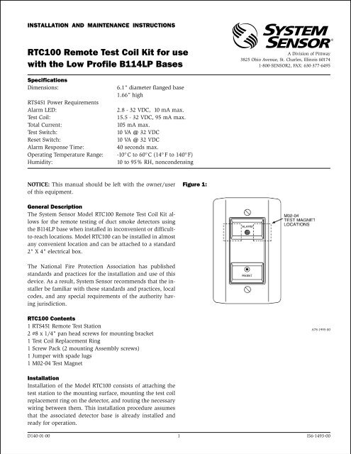
RTC100 Remote Test Coil Kit for use with the Low Profile B114LP ...
RTC100 Remote Test Coil Kit for use with the Low Profile B114LP ...
RTC100 Remote Test Coil Kit for use with the Low Profile B114LP ...

You also want an ePaper? Increase the reach of your titles
YUMPU automatically turns print PDFs into web optimized ePapers that Google loves.
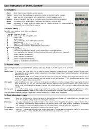
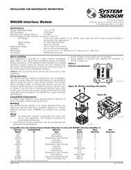
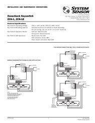
INSTALLATION AND MAINTENANCE INSTRUCTIONS<br />
<strong>RTC100</strong> <strong>Remote</strong> <strong>Test</strong> <strong>Coil</strong> <strong>Kit</strong> <strong>for</strong> <strong>use</strong><br />
<strong>with</strong> <strong>the</strong> <strong>Low</strong> <strong>Profile</strong> <strong>B114LP</strong> Bases<br />
A Division of Pittway<br />
3825 Ohio Avenue, St. Charles, Illinois 60174<br />
1-800-SENSOR2, FAX: 630-377-6495<br />
Specifications<br />
Dimensions:<br />
RTS451 Power Requirements<br />
Alarm LED:<br />
<strong>Test</strong> <strong>Coil</strong>:<br />
Total Current:<br />
<strong>Test</strong> Switch:<br />
Reset Switch:<br />
Alarm Response Time:<br />
Operating Temperature Range:<br />
Humidity:<br />
6.1" diameter flanged base<br />
1.66” high<br />
2.8 - 32 VDC, 10 mA max.<br />
15.5 - 32 VDC, 95 mA max.<br />
105 mA max.<br />
10 VA @ 32 VDC<br />
10 VA @ 32 VDC<br />
40 seconds max.<br />
-10°C to 60°C (14° F to 140°F)<br />
10 to 95% RH, noncondensing<br />
NOTICE: This manual should be left <strong>with</strong> <strong>the</strong> owner/<strong>use</strong>r<br />
of this equipment.<br />
Figure 1:<br />
General Description<br />
The System Sensor Model <strong>RTC100</strong> <strong>Remote</strong> <strong>Test</strong> <strong>Coil</strong> <strong>Kit</strong> allows<br />
<strong>for</strong> <strong>the</strong> remote testing of duct smoke detectors using<br />
<strong>the</strong> <strong>B114LP</strong> base when installed in inconvenient or difficultto-reach<br />
locations. Model <strong>RTC100</strong> can be installed in almost<br />
any convenient location and can be attached to a standard<br />
2" X 4" electrical box.<br />
The National Fire Protection Association has published<br />
standards and practices <strong>for</strong> <strong>the</strong> installation and <strong>use</strong> of this<br />
device. As a result, System Sensor recommends that <strong>the</strong> installer<br />
be familiar <strong>with</strong> <strong>the</strong>se standards and practices, local<br />
codes, and any special requirements of <strong>the</strong> authority having<br />
jurisdiction.<br />
<strong>RTC100</strong> Contents<br />
1 RTS451 <strong>Remote</strong> <strong>Test</strong> Station<br />
2 #8 x 1/4" pan head screws <strong>for</strong> mounting bracket<br />
1 <strong>Test</strong> <strong>Coil</strong> Replacement Ring<br />
1 Screw Pack (2 mounting Assembly screws)<br />
1 Jumper <strong>with</strong> spade lugs<br />
1 M02-04 <strong>Test</strong> Magnet<br />
A78-1995-00<br />
Installation<br />
Installation of <strong>the</strong> Model <strong>RTC100</strong> consists of attaching <strong>the</strong><br />
test station to <strong>the</strong> mounting surface, mounting <strong>the</strong> test coil<br />
replacement ring on <strong>the</strong> detector, and routing <strong>the</strong> necessary<br />
wiring between <strong>the</strong>m. This installation procedure assumes<br />
that <strong>the</strong> associated detector base is already installed and<br />
ready <strong>for</strong> operation.<br />
D140-01-00 1 I56-1493-00
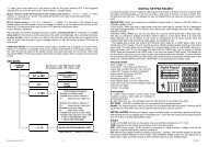
A. <strong>Test</strong> <strong>Coil</strong> Mounting<br />
1. Remove <strong>the</strong> decorative ring from <strong>the</strong> <strong>B114LP</strong> base by<br />
rotating it in ei<strong>the</strong>r direction to release <strong>the</strong> hooks.<br />
Separate <strong>the</strong> ring from <strong>the</strong> base.<br />
2. Position <strong>the</strong> <strong>Test</strong> <strong>Coil</strong> Replacement Ring Assembly on<br />
<strong>the</strong> base, as shown in Figure 2. Be sure to position <strong>the</strong><br />
test coil directly over <strong>the</strong> 4-Position Terminal Block.<br />
O<strong>the</strong>rwise, <strong>the</strong> coil may not activate <strong>the</strong> switch during<br />
a test.<br />
3. Route <strong>the</strong> <strong>the</strong> <strong>Test</strong> <strong>Coil</strong> Replacement Ring Assembly<br />
wires through <strong>the</strong> slot in <strong>the</strong> base as indicated in<br />
Figure 2.<br />
4. Rotate <strong>the</strong> ring in ei<strong>the</strong>r direction until it snaps in<br />
place. Dress all wiring, as needed.<br />
B. Wiring<br />
1. Route four wires from <strong>the</strong> <strong>B114LP</strong> to <strong>the</strong> test station<br />
mounting location. Be sure to comply <strong>with</strong> all applicable<br />
electrical codes when installing this wiring.<br />
This includes selecting <strong>the</strong> proper wire size and routing<br />
through conduit, if necessary.<br />
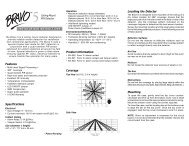
2. Connect <strong>the</strong> wiring to <strong>the</strong> <strong>B114LP</strong> Base and RTS451<br />
<strong>Test</strong> Station, as shown in Figure 3.<br />
Figure 2. Ring Replacement:<br />
TEST<br />
COIL<br />
4-POSITION<br />
TERMINAL<br />
BLOCK<br />
A78-2513-02<br />
C. <strong>Test</strong> Station Mounting<br />
Attach <strong>the</strong> test station to a standard 2" X 4" electrical<br />
box, using <strong>the</strong> screws supplied <strong>with</strong> <strong>the</strong> box.<br />
Operation<br />
<strong>Test</strong><br />
Position <strong>the</strong> painted side of <strong>the</strong> test magnet on <strong>the</strong> RTS451<br />
<strong>Test</strong> Station on ei<strong>the</strong>r <strong>the</strong> left or right side of <strong>the</strong> LED as<br />
shown in Figure 1. The LED should light <strong>with</strong>in 40 seconds,<br />
indicating that <strong>the</strong> detector being is latched in alarm.<br />
Reset<br />
Reset <strong>the</strong> detector by inserting a narrow bladed pocket<br />
screwdriver, or o<strong>the</strong>r similar tool, into <strong>the</strong> RESET hole on<br />
<strong>the</strong> front of <strong>the</strong> test station. Gently press until <strong>the</strong> LED<br />
turns off.<br />
Figure 3. <strong>RTC100</strong> Wiring Diagram:<br />
<strong>B114LP</strong><br />
REMOTE<br />
ANNUNCIATOR (+)<br />
TEST COIL (+)<br />
RTC (—)<br />
1<br />
2<br />
3<br />
4<br />
5<br />
TEST<br />
COIL<br />
RTS451<br />
1<br />
2<br />
3<br />
RESET<br />
4<br />
5<br />
ALARM<br />
Three-Year Limited Warranty<br />
System Sensor warrants its enclosed remote test coil to be free from defects<br />
in materials and workmanship under normal <strong>use</strong> and service <strong>for</strong> a<br />
period of three years from date of manufacture. System Sensor makes no<br />
o<strong>the</strong>r express warranty <strong>for</strong> this remote test coil. No agent, representative,<br />
dealer, or employee of <strong>the</strong> Company has <strong>the</strong> authority to increase or alter<br />
<strong>the</strong> obligations or limitations of this Warranty. The Company’s obligation<br />
of this Warranty shall be limited to <strong>the</strong> repair or replacement of any part of<br />
<strong>the</strong> remote test coil which is found to be defective in materials or workmanship<br />
under normal <strong>use</strong> and service during <strong>the</strong> three year period commencing<br />
<strong>with</strong> <strong>the</strong> date of manufacture. After phoning System Sensor’s toll<br />
free number 800-SENSOR2 (736-7672) <strong>for</strong> a Return Authorization number,<br />
send defective units postage prepaid to: System Sensor, Repair Department,<br />
RA #__________, 3825 Ohio Avenue, St. Charles, IL 60174. Please<br />
include a note describing <strong>the</strong> malfunction and suspected ca<strong>use</strong> of failure.<br />
The Company shall not be obligated to repair or replace units which are<br />
found to be defective beca<strong>use</strong> of damage, unreasonable <strong>use</strong>, modifications,<br />
or alterations occurring after <strong>the</strong> date of manufacture. In no case<br />
shall <strong>the</strong> Company be liable <strong>for</strong> any consequential or incidental damages<br />
<strong>for</strong> breach of this or any o<strong>the</strong>r Warranty, expressed or implied whatsoever,<br />
even if <strong>the</strong> loss or damage is ca<strong>use</strong>d by <strong>the</strong> Company’s negligence or fault.<br />
Some states do not allow <strong>the</strong> exclusion or limitation of incidental or consequential<br />
damages, so <strong>the</strong> above limitation or exclusion may not apply to<br />
you. This Warranty gives you specific legal rights, and you may also have<br />
o<strong>the</strong>r rights which vary from state to state.<br />
D140-01-00 2 I56-1493-00<br />
© System Sensor 1999