PC4204CX - Walker Home Security
PC4204CX - Walker Home Security
PC4204CX - Walker Home Security

Create successful ePaper yourself
Turn your PDF publications into a flip-book with our unique Google optimized e-Paper software.
®<br />
<strong>PC4204CX</strong><br />
Power Supply / Relay Output / Combus Repeater Module<br />
v 3.0 • Installation Instructions<br />
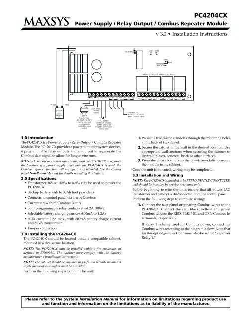
1.0 Introduction<br />
The <strong>PC4204CX</strong> is a Power Supply/Relay Output/ Combus Repeater<br />
Module. The <strong>PC4204CX</strong> provides a power output for system devices,<br />
4 programmable relay outputs and an output to regenerate the<br />
Combus data signal to allow for longer wire runs.<br />
NOTE: Do not use any power supply other than the <strong>PC4204CX</strong> to repower<br />
the Combus. If a power supply other than the <strong>PC4204CX</strong> is used, the<br />
Combus repower function will not operate as intended. See the control<br />
panel Installation Manual for details regarding this feature.<br />
2.0 Specifications<br />
• Transformer 16VAC- 40VA to 80VA may be used to power the<br />
<strong>PC4204CX</strong><br />
• Backup battery 4Ah to 38Ah (not provided)<br />
• Connects to control panel via 4-wire Combus<br />
• Current draw from Combus: 30mA<br />
• Four programmable relay contacts rated 2A, 30VDC<br />
• Selectable battery charging current (800mA or 1.2A)<br />
• AUX current: 2.2A max., with 800mA battery charge current<br />
and 80VA transformer<br />
• Tamper connection<br />
3.0 Installing the <strong>PC4204CX</strong><br />
The <strong>PC4204CX</strong> should be located inside a compatible cabinet,<br />
mounted in a dry, secure location.<br />
NOTE: The <strong>PC4204CX</strong> must be installed within a fire enclosure, as<br />
defined in EN60950. The cabinet must comply with the battery<br />
manufacturer’s installation instructions.<br />
NOTE: The cabinet should be mounted in a safe and reliable manner. A<br />
safety factor of 4 or higher must be provided.<br />
Perform the following steps to mount the unit:<br />
1. Press the five plastic standoffs through the mounting holes<br />
at the back of the cabinet.<br />
2. Secure the cabinet to the wall in the desired location. Use<br />
appropriate wall anchors when securing the cabinet to<br />
drywall, plaster, concrete, brick or other surfaces.<br />
3. Press the circuit board onto the plastic standoffs to secure<br />
the module to the cabinet.<br />
Once the unit is mounted, wiring may be completed.<br />
3.3 Installation and Wiring<br />
NOTE: The <strong>PC4204CX</strong> is intended to be PERMANENTLY CONNECTED<br />
and should be installed by service personnel only.<br />
Before beginning to wire the unit, ensure that all power (AC<br />
transformer and battery) is disconnected from the control panel.<br />
Perform the following steps to complete wiring:<br />
1. Connect the four panel-originating Combus wires to the<br />
<strong>PC4204CX</strong>. Connect the red, black, yellow and green<br />
Combus wires to the RED, BLK, YEL and GRN Combus In<br />
terminals, respectively.<br />
If Relay 1 is being used for Combus power, connect the<br />
Combus wires according to the diagram below. Note that<br />
for this option, jumper Con3 must also be set for “Repower<br />
Relay 1.”<br />
Please refer to the System Installation Manual for information on limitations regarding product use<br />
and function and information on the limitations as to liability of the manufacturer.
Additional modules repowered by the <strong>PC4204CX</strong> should<br />
have the black, yellow and green Combus wires connected<br />
to the BLK, YEL and GRN Combus Out terminals<br />
respectively.<br />
2. Complete all output wiring.<br />
3. Connect the external tamper switch, if used.<br />
Consult the wiring diagrams for further information.<br />
Current Ratings<br />
In order for the system to operate properly, the power output of the<br />
<strong>PC4204CX</strong> module cannot be exceeded. The maximum available AUX<br />
supply current is dependent on the size of the transformer used as<br />
well as the selected battery charge current. Use the following chart<br />
to determine the maximum AUX supply current:<br />
Maximum AUX Supply Current<br />
BATTER<br />
TTERY CHARGE<br />
CURRENT<br />
40VA<br />
TRANSFORMER<br />
80VA<br />
TRANSFORMER<br />
HI-CHRG (800mA) 700mA 2.2A<br />
OFF<br />
HI-CHRG (1.2A) 300mA 1.8A<br />
ON<br />
NOTE: When using the <strong>PC4204CX</strong> to repower additional Combus modules,<br />
current calculations must be made to ensure that the maximum AUX supply<br />
current is not exceeded.<br />
Module Ratings<br />
The current draw of compatible modules is listed below:<br />
Device<br />
Current Draw (mA)<br />
Keypad (LCD45XX) .......................................................................... 50<br />
PC4108A Zone Expander ................................................................. 30<br />
PC4116 Zone Expander .................................................................... 30<br />
PC4164 Wireless Receiver .............................................................. 110<br />
PC4701 Fire Module ......................................................................... 35<br />
PC4702BP Dual Bell Output Module ............................................. 75<br />
<strong>PC4204CX</strong> Relay Output Module ................................................... 30<br />
PC4216 Low Current Output Module ............................................ 15<br />
ESCORT4580 Audio Assistant ....................................................... 150<br />
PC4400 Printer Module .................................................................... 30<br />
PC4820 Access Control Module ...................................................... 35<br />
PC4936 Audio Interface Module ..................................................... 65<br />
PC4401 Serial Interface Module ...................................................... 35<br />
PC4850 Telephone Entry Module ................................................. 135<br />
Calculating Total Current Requirement<br />
Once you have determined which modules will draw power from the<br />
main panel, use the following chart to calculate the Combus current.<br />
Combus Current Calculation Chart<br />
Item Current (mA) x Quantity Total (mA)<br />
Keypad 50 x<br />
PC4108A* 30 x<br />
Current required for connected devices =<br />
PC4116* 30 x<br />
Current required for connected devices =<br />
PC4164 110 x<br />
PC4701 35<br />
PC4702BP 75 x<br />
<strong>PC4204CX</strong> 30 x<br />
PC4216* 15 x<br />
Escort4580 150<br />
Current required for connected devices =<br />
PC4400/4401 30/35 x<br />
PC4820 35 x<br />
PC4850 135 x<br />
PC4936* 65<br />
Alt. Comm.<br />
Total Combus Current =<br />
NOTE: * These modules draw current from the Combus to power devices<br />
external to the module. This current must be added to the total Combus<br />
current. See manufacturer’s specifications for the current draw of each<br />
device. Each LED assembly draws up to 20mA of current.<br />
Combus Operation and Wiring<br />
The Combus is used by the control panel and the modules to<br />
communicate with each other. When the <strong>PC4204CX</strong> is used to repower<br />
and extend the Combus, please refer to the wiring diagram for the<br />
exact wiring procedure. NOTE: Please follow the diagram exactly.<br />
Modules can be home-run, connected in a daisy chain or T-tapped<br />
anywhere on the Combus.<br />
The following rules MUST be followed when wiring the Combus:<br />
1. The Combus must be run in minimum 22-gauge wire.<br />
2. No module can be more than 1000' (305m) in cable length from<br />
the <strong>PC4204CX</strong>.<br />
3. Shielded wire should only be used in areas that present excessive<br />
RF noise or electromagnetic interference. If shielded wire is used,<br />
the maximum distance a module can be located from the<br />
<strong>PC4204CX</strong> is significantly reduced. Check the capacitance rating<br />
of the wire to calculate the maximum distance (see “Capacitance<br />
Limits”). NOTE: Shielded wire is not recommended.<br />
4. The total capacitance of the Combus wiring must not exceed 80nF<br />
between the control panel and <strong>PC4204CX</strong> module or between two<br />
<strong>PC4204CX</strong> modules (see “Capacitance Limits” below).
Long Distance Combus Extensions<br />
The length of Combus from a <strong>PC4204CX</strong> Combus Regenerator can<br />
be extended beyond 1000ft (305m), providing the following<br />
conditions are met:<br />
• Combus must be regenerated and repowered at both ends of<br />
the wire run using the <strong>PC4204CX</strong>.<br />
• No other modules are to be connected along the long distance<br />
wire run.<br />
• A maximum distance of 4000ft (1220m) can be achieved between<br />
two <strong>PC4204CX</strong> devices. To extend further, additional <strong>PC4204CX</strong><br />
devices should be used.<br />
NOTE: The wiring used to connect this equipment must be insulated with<br />
PVC, TFE, PTFE, FEP, neoprene or polymide.<br />
When extending Combus long distances, use the following chart to<br />
determine what gauge of wire is necessary:<br />
Maximum Length<br />
AWG<br />
2000ft (600m) 22<br />
3000ft (900m) 21<br />
4000ft (1200m) 20<br />
Line Loss<br />
When current is drawn through a piece of wire, voltage will be lost<br />
due to the wire’s resistance. This voltage loss must be considered<br />
for all installations.<br />
To ensure proper operation, at least 12.5VDC must be applied to all<br />
modules on the system (when AC is applied and the battery is fully<br />
charged). If less than 12.5VDC is applied, system operation will be<br />
adversely affected.<br />
To correct the problem, try any or all of the following:<br />
1. Connect another <strong>PC4204CX</strong> power supply near the module to<br />
provide power to the Combus.<br />
2. Reduce the length of the Combus run to the module.<br />
3. Increase the gauge of wire.<br />
Capacitance Limits<br />
An increase in capacitance on the Combus will affect data<br />
transmission and will cause the system to slow down. Capacitance<br />
will increase for every foot of wire added to the Combus. The<br />
capacitance rating of the wire used will determine the maximum<br />
length of the Combus, between two <strong>PC4204CX</strong> Combus Repower/<br />
Regenerator modules.<br />
For example, 22-gauge, non-shielded, 4-conductor wire has a typical<br />
capacitance rating of 20 picofarads per foot (which is 20nF/1000’).<br />
For every 1000' of wire added – regardless of where it is run – the<br />
capacitance of the Combus will increase by 20nF.<br />
The following chart indicates the total Combus wire allowed<br />
depending on the capacitance rating of the wire used:<br />
Wire Capacitance per<br />
1000’(300m)<br />
15nF<br />
20nF<br />
25nF<br />
30nF<br />
35nF<br />
40nF<br />
TOTAL Combus Wire<br />
Length<br />
5300’/1616m<br />
4000’/1220m<br />
3200’/976m<br />
2666’/810m<br />
2280’/693m<br />
2000’/608m<br />
Wires run in parallel also increase Combus capacitance. For example,<br />
when using 20nF wire, the following would be some of the<br />
combinations allowed:<br />
• Four wire runs at 1000'/305m each<br />
• Six wire runs at 666'/203m each<br />
• Eight wire runs at 500'/152m each<br />
• 10 wire runs at 400'/122m each etc…<br />
Contact the wire manufacturer for the capacitance ratings of the<br />
wire being used.<br />
3.4 Regenerating Combus<br />
This module will regenerate the Combus signal as it passes from<br />
one side to the other. The LEDs on the module will illuminate<br />
whenever there is activity on either side of the input or output of<br />
the module.<br />
LED 1 illuminates when the module transmits data on ‘Combus In’<br />
LED 2 illuminates when the module transmits data on ‘Combus Out’<br />
The <strong>PC4204CX</strong> module will isolate ‘Combus In’ from any short<br />
circuit problems on ‘Combus Out’. In the event of a problem, the<br />
<strong>PC4204CX</strong> module will generate a module fault along with the<br />
modules on the disabled Combus. This information can be used<br />
to determine which section of Combus is disabled on the system.<br />
When connecting the <strong>PC4204CX</strong> to the Combus, care must be taken<br />
to ensure that the ‘Combus In’ terminals are connected to the<br />
wires originating from the control panel (or a module that may be<br />
situated between the <strong>PC4204CX</strong> and the control panel).<br />
3.5 Applying Power<br />
NOTE: Do not connect power until all wiring is complete.<br />
After all wiring is completed, apply power to the control panel.<br />
Connect the battery leads to the battery, then connect the AC<br />
transformer. Then, connect power to the <strong>PC4204CX</strong>: first connect<br />
the battery leads, then the AC transformer.<br />
For more information on control panel power specifications, see<br />
the control panel Installation Manual.<br />
NOTE: It is the installer’s responsibility to provide adequate protection<br />
for the transformer used in the primary and secondary circuit according<br />
to the rated current of the transformer. The transformer used must be Class2,<br />
Fail Safe as defined within EN61558-1 and must meet the applicable<br />
requirements of the EN60950 Standard. A readily accessible disconnect<br />
device must be incorporated into the fixed wiring and must disconnect<br />
both poles simultaneously. The wiring connected to the <strong>PC4204CX</strong> must<br />
be mechanically protected, routed, supported, clamped or secured in a<br />
manner that prevents excessive strain on wire and terminal connections,<br />
loosening of terminal connections and conducter insulation damage.<br />
NOTE: Do not connect fully discharged (less than 10V) or damaged<br />
batteries to the <strong>PC4204CX</strong>.<br />
4. Enrolling the Module<br />
Once connected, the module must be enrolled on the system. To<br />
enroll the module, perform the following:<br />
1. Enter installer’s programming by pressing [*] [8] [Installer’s Code].<br />
2. Scroll to “Module Hardware” and press the [*] key.<br />
3. Scroll to “Enroll Module” and press the [*] key.<br />
4. Scroll through the different modules until “PC4204” is displayed.<br />
Press the [*] key.<br />
5. The message “Create Tamper on Desired Unit” will be displayed.<br />
To create the required tamper, secure the tamper zone on the<br />
module and then open it. The transition from secure to violated<br />
enrolls the module. After this is done, the keypad will display<br />
the module number and will confirm enrollment (e.g., “PC4204<br />
Mod 01 Enrolled”).<br />
For more information regarding module enrollment, see the control<br />
panel Installation Manual.
5. Programming the Module<br />
To access PC4010/4020 programming, enter [*][8] followed by the<br />
Installer’s Code. Each relay output must be programmed. Please see<br />
the control panel Installation Manual and Programming Worksheets for<br />
a detailed list of output options.<br />
NOTE: Relay 1 must not be programmed if used for Combus power. Ensure<br />
that jumper CON3 is set to “Repower Relay1.”<br />
<strong>PC4204CX</strong> Outputs Module Number: <strong>PC4204CX</strong> # I______I______I (1-16 = XX)<br />
Partition<br />
Output 1 2 3 4 5 6 7 8 Zone Schedule # Pulse Timer<br />
[000702XX01] <strong>PC4204CX</strong> Relay 1 I______I______I I______I______I______I______I______I______I______I______I I______I______I______I I______I______I I______I______I______I<br />
[000702XX02] <strong>PC4204CX</strong> Relay 2 I______I______I I______I______I______I______I______I______I______I______I I______I______I______I I______I______I I______I______I______I<br />
[000702XX03] <strong>PC4204CX</strong> Relay 3 I______I______I I______I______I______I______I______I______I______I______I I______I______I______I I______I______I I______I______I______I<br />
[000702XX04] <strong>PC4204CX</strong> Relay 4 I______I______I I______I______I______I______I______I______I______I______I I______I______I______I I______I______I I______I______I______I<br />
FCC COMPLIANCE STATEMENT<br />
CAUTION: Changes or modifications not expressly approved by Digital <strong>Security</strong> Controls Ltd. could void your authority to use this equipment.<br />
This equipment generates and uses radio frequency energy and if not installed and used properly, in strict accordance with the manufacturer’s instructions, may cause<br />
interference to radio and television reception. It has been type tested and found to comply with the limits for Class B device in accordance with the specifications in<br />
Subpart “B” of Part 15 of FCC Rules, which are designed to provide reasonable protection against such interference in any residential installation. However, there is<br />
no guarantee that interference will not occur in a particular installation. If this equipment does cause interference to television or radio reception, which can be<br />
determined by turning the equipment off and on, the user is encouraged to try to correct the interference by one or more of the following measures:<br />
• Re-orient the receiving antenna<br />
• Relocate the alarm control with respect to the receiver<br />
• Move the alarm control away from the receiver<br />
• Connect the alarm control into a different outlet so that alarm control and receiver are on different circuits.<br />
If necessary, the user should consult the dealer or an experienced radio/television technician for additional suggestions. The user may find the following<br />
booklet prepared by the FCC helpful: “How to Identify and Resolve Radio/Television Interference Problems”. This booklet is available from the U.S.<br />
Government Printing Office, Washington, D.C. 20402, Stock # 004-000-00345-4.<br />
©2001 Digital <strong>Security</strong> Controls Ltd.<br />
Toronto, Canada • www.dsc.com<br />
Technical Support: 1-800-387-3630<br />
Printed in Canada 29005814 R003