SpectrAlert SP2C Series Ceiling Mount Speaker/Strobes for Fire ...
SpectrAlert SP2C Series Ceiling Mount Speaker/Strobes for Fire ...
SpectrAlert SP2C Series Ceiling Mount Speaker/Strobes for Fire ...
Create successful ePaper yourself
Turn your PDF publications into a flip-book with our unique Google optimized e-Paper software.
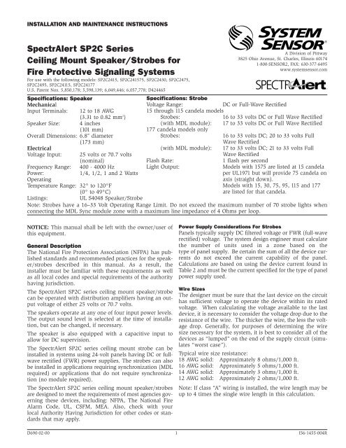
INSTALLATION AND MAINTENANCE INSTRUCTIONS<br />
<strong>SpectrAlert</strong> <strong>SP2C</strong> <strong>Series</strong><br />
<strong>Ceiling</strong> <strong>Mount</strong> <strong>Speaker</strong>/<strong>Strobes</strong> <strong>for</strong><br />
<strong>Fire</strong> Protective Signaling Systems<br />
For use with the following models: <strong>SP2C</strong>2415, <strong>SP2C</strong>241575, <strong>SP2C</strong>2430, <strong>SP2C</strong>2475,<br />
<strong>SP2C</strong>2495, <strong>SP2C</strong>24115, <strong>SP2C</strong>24177<br />
U.S. Patent Nos. 5,850,178; 5,598,139; 6,049,446; 6,057,778; D424465<br />
Specifications: <strong>Speaker</strong><br />
Mechanical<br />
Input Terminals: 12 to 18 AWG<br />
(3.31 to 0.82 mm 2 )<br />
<strong>Speaker</strong> Size: 4 inches<br />
(101 mm)<br />
Overall Dimensions: 6.8″ diameter<br />
(173 mm)<br />
Electrical<br />
Voltage Input:<br />
25 volts or 70.7 volts<br />
(nominal)<br />
400 - 4000 Hz<br />
1/4, 1/2, 1 and 2 Watts<br />
Frequency Range:<br />
Power:<br />
Operating<br />
Temperature Range: 32° to 120°F<br />
(0° to 49°C)<br />
A Division of Pittway<br />
3825 Ohio Avenue, St. Charles, Illinois 60174<br />
1-800-SENSOR2, FAX: 630-377-6495<br />
www.systemsensor.com<br />
Specifications: Strobe<br />
Voltage Range:<br />
DC or Full-Wave Rectified<br />
15 through 115 candela models<br />
<strong>Strobes</strong>:<br />
16 to 33 volts DC or Full Wave Rectified<br />
(with MDL module): 17 to 33 volts DC or Full Wave Rectified<br />
177 candela models only<br />
<strong>Strobes</strong>:<br />
16 to 33 volts DC; 20 to 33 volts Full<br />
Wave Rectified<br />
(with MDL module): 17 to 33 volts DC; 21 to 33 volts Full<br />
Wave Rectified<br />
Flash Rate:<br />
1 flash per second<br />
Light Output:<br />
Models with 1575 are listed at 15 candela<br />
per UL1971 but will provide 75 candela on<br />
axis (straight down).<br />
Models with 15, 30, 75, 95, 115 and 177<br />
are listed <strong>for</strong> that candela.<br />
Listings:<br />
UL S4048 <strong>Speaker</strong>/Strobe<br />
Note: <strong>Strobes</strong> have a 16–33 Volt Operating Range Limit. Do not exceed the maximum number of 70 strobe lights when<br />
connecting the MDL Sync module zone with a maximum line impedance of 4 Ohms per loop.<br />
NOTICE: This manual shall be left with the owner/user of<br />
this equipment.<br />
General Description<br />
The National <strong>Fire</strong> Protection Association (NFPA) has published<br />
standards and recommended practices <strong>for</strong> the speaker/strobes<br />
described in this manual. As a result, the<br />
installer must be familiar with these requirements as well<br />
as all local codes and special requirements of the authority<br />
having jurisdiction.<br />
The <strong>SpectrAlert</strong> <strong>SP2C</strong> series ceiling mount speaker/strobe<br />
can be operated with distribution amplifiers having an output<br />
voltage of either 25 volts or 70.7 volts.<br />
The speakers operate at any one of four input power levels.<br />
The output sound level is selected at the time of installation,<br />
but can be changed, if necessary.<br />
The speaker is also equipped with a capacitive input to<br />
allow <strong>for</strong> DC supervision.<br />
The <strong>SpectrAlert</strong> <strong>SP2C</strong> series ceiling mount strobe can be<br />
installed in systems using 24-volt panels having DC or fullwave<br />
rectified (FWR) power supplies. The strobes can also<br />
be installed in applications requiring synchronization (MDL<br />
required) or applications that do not require synchronization<br />
(no module required).<br />
The <strong>SpectrAlert</strong> <strong>SP2C</strong> series ceiling mount speaker/strobes<br />
are designed to meet the requirements of most agencies governing<br />
these devices, including: NFPA, The National <strong>Fire</strong><br />
Alarm Code, UL, CSFM, MEA. Also, check with your<br />
local Authority Having Jurisdiction <strong>for</strong> other codes or standards<br />
that may apply.<br />
Power Supply Considerations For <strong>Strobes</strong><br />
Panels typically supply DC filtered voltage or FWR (full-wave<br />
rectified) voltage. The system design engineer must calculate<br />
the number of units used in a zone based on the<br />
type of panel supply. Be certain the sum of all the device currents<br />
do not exceed the current capability of the panel.<br />
Calculations are based on using the device current found in<br />
Table 2 and must be the current specified <strong>for</strong> the type of panel<br />
power supply used.<br />
Wire Sizes<br />
The designer must be sure that the last device on the circuit<br />
has sufficient voltage to operate the device within its rated<br />
voltage. When calculating the voltage available to the last<br />
device, it is necessary to consider the voltage drop due to the<br />
resistance of the wire. The thicker the wire, the less the voltage<br />
drop. Generally, <strong>for</strong> purposes of determining the wire<br />
size necessary <strong>for</strong> the system, it is best to consider all of the<br />
devices as “lumped” on the end of the supply circuit (simulates<br />
“worst case”).<br />
Typical wire size resistance:<br />
18 AWG solid: Approximately 8 ohms/1,000 ft.<br />
16 AWG solid: Approximately 5 ohms/1,000 ft.<br />
14 AWG solid: Approximately 3 ohms/1,000 ft.<br />
12 AWG solid: Approximately 2 ohms/1,000 ft.<br />
Note: If class “A” wiring is installed, the wire length may be<br />
up to 4 times the single wire length in this calculation.<br />
D690-02-00 1 I56-1455-004R
Example: Assume you have 10 devices on a zone and each<br />
requires 50 mA average and 2000 Ft. of 14 AWG wiring<br />
(total length=outgoing +return). The voltage at the end<br />
of the loop is 0.050 amps per device x 10 devices x 3 ohms<br />
1,000 ft. x 2000 ft =3 volts drop.<br />
The same number of devices using 12 AWG wire will produce<br />
only 2 volts drop. The same devices using 18 AWG<br />
wire will produce 8 volts drop. Consult your panel manufacturer’s<br />
specifications, as well as <strong>SpectrAlert</strong>’s operating<br />
voltage range to determine acceptable voltage drop.<br />
Electrical<br />
1. Connect the speaker/strobe as shown in Figure 1. Keep<br />
in mind that even though the speaker and strobe are a<br />
single mechanical unit, they are electrically independent<br />
and require separate power sources.<br />
NOTE: Do NOT loop electrical wiring under terminal<br />
screws. Wires connecting the device to the control<br />
panel must be broken at the device terminal connection<br />
in order to maintain electrical supervision.<br />
Figure 2. Voltage and Power Selection:<br />
Installation<br />
All wiring must be installed in compliance with the<br />
National Electrical Code (NEC) and applicable local codes<br />
as well as special requirements of the authority having<br />
jurisdiction, using the proper wire size. This also includes<br />
all applicable NFPA Standards, ANSI/UL 1480, UL 1971 and<br />
NEC 760.<br />
Figure 1. Electrical connections:<br />
INPUT FROM<br />
AMPLIFIER<br />
INPUT FROM<br />
POWER SUPPLY<br />
TO NEXT<br />
SPEAKER OR EOL<br />
TO NEXT<br />
STROBE OR EOL<br />
NOTE: Supply power <strong>for</strong> strobe must be continuous <strong>for</strong><br />
proper operation.<br />
CORRECT<br />
SW1<br />
25.0V<br />
70.7V<br />
2W<br />
1W<br />
1/2W<br />
1/4W<br />
INCORRECT<br />
SW1<br />
25.0V<br />
70.7V<br />
2W<br />
1W<br />
1/2W<br />
1/4W<br />
Table 1. Sound levels <strong>for</strong> each trans<strong>for</strong>mer<br />
power tap:<br />
87 84 81 78<br />
Table 2. Current draw of strobes:<br />
NOTE: The <strong>SP2C</strong>24177 strobes were only tested at the 20-33 Volt-FWR limits and 16-33 Volt DC limits, all other <strong>SP2C</strong><br />
strobes were only tested at the 16-33 Volt-FWR/DC limits. This does not include the 80% low end or 110% high<br />
end voltage limits.<br />
Average Mean Method:<br />
Candela<br />
15<br />
15/75<br />
30<br />
75<br />
95<br />
115<br />
177<br />
Average Mean Current (mA)<br />
24V Models<br />
16V 20V 24V 33V<br />
DC FWR FWR DC FWR DC FWR<br />
78 81 48 55 41 51<br />
81 94 56 62 47 62<br />
114 91 68 79 56 73<br />
179 179 127 140 101 126<br />
223 227 153 173 122 163<br />
290 232 191 230 156 212<br />
453 338 291 300 208 241<br />
Average RMS Method:<br />
Candela<br />
15<br />
15/75<br />
30<br />
75<br />
95<br />
115<br />
177<br />
Average RMS Current (mA)<br />
24V Models<br />
16V 20V 24V 33V<br />
DC FWR FWR DC FWR DC FWR<br />
74 71 61 74 54 74<br />
86 81 71 81 62 86<br />
112 103 90 98 78 99<br />
209 178 167 168 143 154<br />
269 242 213 208 180 204<br />
336 300 257 268 218 248<br />
521 412 394 370 315 327<br />
Peak Current (mA)<br />
24V Models<br />
16V 20V 24V 33V<br />
DC FWR FWR DC FWR DC FWR<br />
164 232 170 242 170 224<br />
174 238 172 258 168 228<br />
238 288 226 318 218 298<br />
418 436 398 462 384 486<br />
540 562 534 560 518 552<br />
644 668 612 712 576 728<br />
952 1092 912 1104 872 1184<br />
UL<br />
Reverberant<br />
(dBA @ 10 ft.)<br />
Anechoic<br />
(dBA @ 10 ft.)<br />
In Rush Current (mA)<br />
24V Models<br />
16V 20V 24V 33V<br />
DC FWR FWR DC FWR DC FWR<br />
91 118 133 177 188 252<br />
91 115 134 179 182 237<br />
94 116 137 179 184 244<br />
99 118 133 177 186 238<br />
92 115 132 176 187 244<br />
81 108 118 175 174 249<br />
79 148 126 170 171 234<br />
2W 1W 1/2W 1/4W<br />
84 81 78 75<br />
2W 1W 1/2W 1/4W<br />
D690-02-00 2 I56-1455-004R
2. See Figure 2 as an example of how to select a 1/4 Watt<br />
input when a 25 volt amplifier is being used. Notice that<br />
the header, SW1, has two shunts. One shunt is used to<br />
select either 25 or 70.7 volts input. The other shunt is<br />
used to select input power of 1/4, 1/2, 1 or 2 Watts.<br />
Table 1 lists the UL reverberant and anechoic output<br />
sound levels <strong>for</strong> each power tap on the <strong>SP2C</strong> series ceiling<br />
mount speaker/strobes.<br />
Figure 4: Positioning <strong>for</strong> maximum brightness<br />
NOTE: For maximum brightness, unit must be mounted<br />
with flash angles as shown.<br />
CAUTION<br />
Signal levels exceeding 130% rated signal voltage can<br />
damage the speaker. Consequently, an incorrect tap connection<br />
may cause speaker damage. This means that if a<br />
25V tap is selected when a 70.7V amplifier is being used,<br />
speaker damage may result. There<strong>for</strong>e, be sure to select<br />
the proper taps <strong>for</strong> the amplifier voltage/input power<br />
level combination being used.<br />
<strong>Mount</strong>ing<br />
The <strong>SP2C</strong> series ceiling mount speaker/strobe can be flush<br />
mounted on a 4″ x 4″ x 2-1/8″ back box. Use two 8-32 x<br />
1-3/4″ pan head screws to attach the speaker to the back<br />
box (See Fig. 3).<br />
Figure 3: Flush mount back box<br />
Note: Any combination of 4″x4″<br />
back box and extension<br />
ring may not exceed a<br />
depth of 3-5/8″.<br />
D690-02-00 3 I56-1455-004R
Please refer to insert <strong>for</strong> the Limitations of <strong>Fire</strong> Alarm Systems<br />
WARNING<br />
The Limitations of <strong>Ceiling</strong> <strong>Mount</strong> <strong>Speaker</strong>/<strong>Strobes</strong><br />
If either of the voltage select or power select shunts is not plugged into<br />
one of the appropriate option positions, the speaker will not sound and<br />
there will be no trouble indication at the panel. Always make sure that the<br />
individual speakers are tested after installation per NFPA regulations.<br />
The speaker may not be heard. The loudness of the speaker meets (or<br />
exceeds) the current Underwriters Laboratories’ standards. However, the<br />
speaker may not attract the attention of a sound sleeper or one who has<br />
recently used drugs or has been drinking alcoholic beverages. The speaker<br />
may not be heard if it is placed on a different floor from the person in<br />
hazard or if placed too far away to be heard over the ambient noise.<br />
Traffic, air conditioners, machinery, or music appliances may prevent even<br />
alert persons from hearing the alarm. The speaker may not be heard by<br />
persons who are hearing impaired.<br />
The signal strobe may not be seen. The electronic visual warning signal<br />
uses an extremely reliable xenon flash tube. It flashes at least once every<br />
second. The strobe must not be installed in direct sunlight or areas of high<br />
light intensity (over 60 foot candles) where the visual flash might be disregarded<br />
or not seen. The strobe may not be seen by the visually impaired.<br />
The signal strobe may cause seizures. Individuals who have positive<br />
photic response to visual stimuli with seizures, such as persons with<br />
epilepsy, should avoid prolonged exposure to environments in which<br />
strobe signals, including this strobe, are activated.<br />
The signal strobe cannot operate from coded power supplies. Coded<br />
power supplies produce interrupted power. The strobe must have an uninterrupted<br />
source of power in order to operate correctly. System Sensor recommends<br />
that the horn and signal strobe always be used in combination<br />
so that the risks from any of the above limitations are minimized.<br />
System Sensor warrants its enclosed speaker to be free from defects in<br />
materials and workmanship under normal use and service <strong>for</strong> a period of<br />
three years from date of manufacture. System Sensor makes no other<br />
express warranty <strong>for</strong> this speaker. No agent, representative, dealer, or<br />
employee of the Company has the authority to increase or alter the obligations<br />
or limitations of this Warranty. The Company’s obligation of this<br />
Warranty shall be limited to the repair or replacement of any part of the<br />
speaker which is found to be defective in materials or workmanship under<br />
normal use and service during the three year period commencing with the<br />
date of manufacture. After phoning System Sensor’s toll free number 800-<br />
SENSOR2 (736-7672) <strong>for</strong> a Return Authorization number, send defective<br />
units postage prepaid to: System Sensor, Repair Department, RA<br />
Three-Year Limited Warranty<br />
#__________, 3825 Ohio Avenue, St. Charles, IL 60174. Please include a<br />
note describing the malfunction and suspected cause of failure. The<br />
Company shall not be obligated to repair or replace units which are found<br />
to be defective because of damage, unreasonable use, modifications, or<br />
alterations occurring after the date of manufacture. In no case shall the<br />
Company be liable <strong>for</strong> any consequential or incidental damages <strong>for</strong> breach<br />
of this or any other Warranty, expressed or implied whatsoever, even if the<br />
loss or damage is caused by the Company’s negligence or fault. Some<br />
states do not allow the exclusion or limitation of incidental or consequential<br />
damages, so the above limitation or exclusion may not apply to<br />
you. This Warranty gives you specific legal rights, and you may also have<br />
other rights which vary from state to state.<br />
D690-02-00 4 I56-1455-004R<br />
© System Sensor 2000


