
Create successful ePaper yourself
Turn your PDF publications into a flip-book with our unique Google optimized e-Paper software.
+<br />
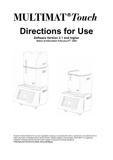
Directions for Use<br />
Software Version 2.1 and higher<br />
Status of Information February 21 st , 20<strong>03</strong><br />
All parts of these directions for use are copyrighted. Copying or circulating the whole or partial text is only allowed with a<br />
written permission of Dentsply DeTrey DeTech GmbH. Violation obliges to compensation. MULTIMAT © is a registered<br />
trademark of Dentsply DeTrey DeTech GmbH. Subject to technical and design alterations.<br />
© Dentsply DeTrey DeTech GmbH, Hanau-Wolfgang
Introduction<br />
Dear customer,<br />
Thank you for having bought Dentsply’s Multimat ® Touch. This furnace represents an<br />
advanced, state of the art product of the Multimat ® generation. By selecting from various<br />
different firing modes, this furnace allows you to fire (&press) the materials from a broad<br />
range of different manufacturers. Easy, menu-driven operation keeps training times to a<br />
minimum.<br />
The Multimat ® Touch is equipped with 300 freely programmable programs. 62 preset<br />
programs of Dentsply’s ceramics come on top, meaning that they do not lower the amount of<br />
individual programs. The Touch Screen allows direct interaction and a quick selection of<br />
functions. All firing data are visualized over a color graphic display. Control of the<br />
measurement and control processes is effected by means of a 32 bit microprocessor.<br />
Furthermore the Multimat ® Touch&Press version allows pressable dental ceramics to be<br />
processed in addition to the usual firing options. This device complies with all applicable<br />
current EU directives and VDE/UL safety regulations.<br />
Before startup, please read the entire operating instructions!<br />
2
Contents<br />
INTRODUCTION.....................................................................................................................2<br />
MEANING OF WARNING AND CAUTION NOTES:.........................................................6<br />
1. DESCRIPTION OF PARTS...............................................................................................7<br />
1.1 Description of parts...................................................................................................... 8<br />
1.2 Technical data............................................................................................................... 9<br />
1.3 Environmental conditions............................................................................................ 9<br />
2. SAFE USE .........................................................................................................................10<br />
2.1 Use within specifications........................................................................................... 10<br />
2.2 Hazards and safety notes.......................................................................................... 11<br />
3. SETUP AND FIRST USE................................................................................................12<br />
3.1 Unpacking.................................................................................................................... 12<br />
3.2 Check accessories..................................................................................................... 12<br />
3.3 Setup ............................................................................................................................ 12<br />
3.4 First use ....................................................................................................................... 12<br />
3.4.1 Start screen display....................................................................................................13<br />
3.4.2 Language selection.....................................................................................................13<br />
3.4.3 Introduction................................................................................................................13<br />
3.4.4 Installation and safety notes ........................................................................................14<br />
3.4.5 Automatic Self-Test ....................................................................................................14<br />
3.4.6 Basic settings ............................................................................................................15<br />
3.4.6.1 Temperature mode ................................................................................................................................15<br />
3.4.6.2 Night/Standby Temperature..................................................................................................................15<br />
3.4.6.3 Vacuum unit.............................................................................................................................................15<br />
3.4.6.4 System Time............................................................................................................................................15<br />
3.4.6.5 Date ...........................................................................................................................................................16<br />
3.4.6.6 Acoustic Signal........................................................................................................................................16<br />
3.4.6.7 Idle temperature......................................................................................................................................16<br />
3.4.6.8 Max-Temp.................................................................................................................................................16<br />
3.4.6.9 Data output...............................................................................................................................................16<br />
3.4.6.10 Screen brightness................................................................................................................................16<br />
3.4.7 Porcelain type............................................................................................................17<br />
3.4.8 Program list: special programs ....................................................................................17<br />
3.5 Test programs ............................................................................................................. 18<br />
3.5.1 Test program DeTrey / Ceramco / External ...................................................................18<br />
3.5.2 Start a test program....................................................................................................18<br />
4. PRACTICAL APPLICATION: AN INTRODUCTION ..................................................20<br />
4.1 Firing parameter limit values..................................................................................... 20<br />
4.2 Display.......................................................................................................................... 20<br />
4.3 Screen display functions ........................................................................................... 21<br />
4.4 Keyboard functions .................................................................................................... 22<br />
4.5 Main menu.................................................................................................................... 23<br />
4.5.1 Configuration ...............................................................................................................24<br />
4.5.2 Furnace Parameters ...................................................................................................25<br />
5.5.2.1 Reset temperature offset......................................................................................................................25<br />
4.5.2.2 Vacuum test.............................................................................................................................................25<br />
4.5.2.3 Reset Language:....................................................................................................................................25<br />
3
4.5.2.4 Heating % (Power factor) ......................................................................................................................25<br />
4.5.2.5 Reset Muffle Operating Hours..............................................................................................................26<br />
4.5.2.6 Statistical data .........................................................................................................................................26<br />
4.5.3 Smart Card ................................................................................................................26<br />
4.5.4 Delete programs.........................................................................................................26<br />
4.5.4.1 Single program .......................................................................................................................................26<br />
4.5.4.2 Delete all individual programs.............................................................................................................27<br />
4.5.4.3 Delete all preset / all special programs.............................................................................................27<br />
4.5.5 Online Diagnosis System (ODS optional)......................................................................26<br />
5. CREATE AN OWN PROGRAM......................................................................................27<br />
5.1 Firing Modes................................................................................................................ 28<br />
5.2 Program type ............................................................................................................... 28<br />
5.3 Program list.................................................................................................................. 28<br />
5.4 Text input..................................................................................................................... 29<br />
5.5 Setting the firing parameters.................................................................................... 29<br />
5.5.1 Setting Low temperature .............................................................................................29<br />
5.5.2 Setting Predry time.....................................................................................................29<br />
5.5.3 Setting Drying time.....................................................................................................29<br />
5.5.4 Setting Preheating time...............................................................................................30<br />
5.5.5 Setting Vacuum level ..................................................................................................30<br />
5.5.6 Setting Heat rate........................................................................................................30<br />
5.5.7 Setting High temperature.............................................................................................30<br />
5.5.8 Setting Vacuum time ..................................................................................................30<br />
5.5.9 Setting Firing time ......................................................................................................30<br />
5.5.10 Setting Tempering temperature ..................................................................................30<br />
5.5.11 Setting the tempering time.........................................................................................31<br />
5.5.12 Setting the cooling stage...........................................................................................31<br />
5.6 Save program.............................................................................................................. 31<br />
5.7 Start a program............................................................................................................ 32<br />
5.8 Standard functions ..................................................................................................... 32<br />
5.8.1 Recall a program ........................................................................................................32<br />
5.8.2 Save program.............................................................................................................32<br />
5.8.3 Changing a program....................................................................................................33<br />
5.8.4 Changing a program during a firing sequence (Overwrite) ................................................33<br />
5.8.5 Copy program ............................................................................................................33<br />
5.8.6 Deleting programs ......................................................................................................33<br />
5.9 Pressing........................................................................................................................ 33<br />
6. SPECIAL FUNCTIONS ...................................................................................................35<br />
6.1 Night/standby-temperature........................................................................................ 35<br />
6.2 Quick cooling............................................................................................................... 35<br />
6.3 View function............................................................................................................... 35<br />
6.4 Voltage loss bridging (Power failure recovery)...................................................... 36<br />
6.5 Check firing chamber temperature .......................................................................... 36<br />
6.6 Night mode................................................................................................................... 37<br />
6.7 Pre select activation timer......................................................................................... 37<br />
6.8 Vacuum test ................................................................................................................. 38<br />
6.9 Printer/PC (Program for PC optional) ...................................................................... 38<br />
6.10 Acoustic Signal.......................................................................................................... 38<br />
6.11 Software Update ....................................................................................................... 38<br />
6.12 Program sorting according to name or program number.................................... 39<br />
6.13 Change standard drying position and steps......................................................... 39<br />
6.14 Changing the tempering position of the firing chamber..................................... 39<br />
6.15 Display time and date ............................................................................................... 40<br />
4
6.16 Smart Card................................................................................................................. 40<br />
6.16.2 Program transfer furnace fi Smart Card....................................................... 41<br />
6.16.3 Program transfer Smart Card fi Furnace...................................................... 42<br />
7. Service and maintenance.............................................................................................. 42<br />
7.1 Lift................................................................................................................................. 42<br />
7.2 Firing platform complete with firing platform carrier............................................. 42<br />
7.3 Vacuum pump .............................................................................................................. 42<br />
7.4 Replacement of firing muffle..................................................................................... 43<br />
7.5 Replacement of control unit...................................................................................... 44<br />
7.6 Inspections .................................................................................................................. 45<br />
7.7 Cleaning notes............................................................................................................ 45<br />
8. ERRORS AND REMEDIES............................................................................................46<br />
9. PRESET PROGRAMS.....................................................................................................49<br />
9.1 Firing Table for Ceramco 3 Metal Ceramics (DeTrey Mode)............................... 49<br />
9.2 Firing table for Finesse metal ceramics (DeTrey Mode)....................................... 50<br />
9.3 Firing table for Finesse All Ceramic (DeTrey Mode).............................................. 51<br />
9.4 Firing table for Finesse; FAC and Ceramco II (Ceramco Mode)........................... 52<br />
10. SOFTWARE ....................................................................................................................53<br />
11. SUBSIDIARIES...............................................................................................................54<br />
12. INDEX...............................................................................................................................55<br />
5
Meaning of Warning and Caution Notes<br />
Warning!<br />
This symbol indicates particularly important notes and instructions in respect of<br />
which any non-compliance may cause injury or accident hazards.<br />
Caution!<br />
Hot surface<br />
This symbol is placed everywhere you could get in contact with a hot surface.<br />
Text in Italics means that this part only refers to the furnace version<br />
Multimat ® Touch&Press<br />
6
1. Description of parts<br />
1.1 Description of parts<br />
1. Press hood<br />
2. Cover<br />
3. Cooling jacket<br />
4. Support<br />
5. Firing platform<br />
6. Firing platform carrier<br />
7. Work storage platform<br />
8. Control casing<br />
9. Smart card slot<br />
10. Interface RS 232 (Printer/PC port)<br />
11. Interface RJ 485 (for PC network)<br />
12. Touch Screen<br />
13. Control section ( Controller)<br />
14. Equipment fuses<br />
15. Mains socket<br />
16. Vacuum connection<br />
17. Vacuum pump socket<br />
18. Compressed air connection<br />
19. Filter control<br />
20. Muffle<br />
21. Press platform (without picture)<br />
8
1.2 Technical data<br />
Multimat ® Touch<br />
Height: closed approx. 441 mm<br />
Open approx. 585 mm<br />
Width:<br />
approx. 320 mm<br />
Depth:<br />
approx. 425 mm<br />
Voltage:<br />
approx. 220/230 V for countries with 220/230 V<br />
approx. 100 V for countries with 100 V<br />
approx. 110 / 115 V for countries with 110/115 V<br />
approx. 125 V for countries with 125 V<br />
Frequency:<br />
50/ 60 Hz<br />
Overvoltage category:<br />
II<br />
Degree of contamination: 2<br />
Protection class:<br />
I<br />
Performance:<br />
1350 VA without pump<br />
Fuses:<br />
2 x 16 A slow fuses, 6.3 x 32 mm, 250 V<br />
Pump plug:<br />
2.5 A<br />
Weight:<br />
approx. 22 kg<br />
Multimat ® Touch&Press<br />
Height: closed approx. 593 mm<br />
open approx. 748 mm<br />
Width:<br />
approx. 320 mm<br />
Depth:<br />
approx. 425 mm<br />
Press pressure:<br />
2.7 bar<br />
Voltage:<br />
approx. 220/230 V for Countries with 220/230 V<br />
approx. 110 / 115 V for Countries with 110/115V<br />
approx. 125 V for Countries with 125 V<br />
Frequency:<br />
50/ 60 Hz<br />
Overvoltage category:<br />
II<br />
Degree of contamination: 2<br />
Protection class:<br />
I<br />
Performance:<br />
1350 VA without pump<br />
Fuses:<br />
2 x 15 A slow fuses, 6.3 x 32 mm, 250 V<br />
Pump plug:<br />
2.5 A<br />
Weight:<br />
approx. 25 kg<br />
1.3 Environmental conditions<br />
Temperature: 2 °C to 40 °C<br />
Relative air humidity: 80% at 31 °C<br />
Height:<br />
3500 m above sea level<br />
9
2. Safe use<br />
2.1 Use within specifications<br />
Warning!<br />
The Multimat ® Touch has been designed and is exclusively intended for firing/ pressing<br />
dental ceramics. Dentsply will not be liable for any damage resulting from any other use that<br />
is not within our specifications. Programs with temperatures above 1000 °C reduce the life<br />
span of the muffle, the press cylinder and the press valve. In this case those items are<br />
excluded from warranty.<br />
Such use within specifications also includes all notes, instructions, and information contained<br />
in these operating instructions as well as all notes, instructions, and information contained in<br />
the separate operating instructions provided by the vacuum pump manufacturer and the<br />
Online Diagnose Systems.<br />
Repairs and maintenance are only to be carried out by Dentsply service technicians or<br />
authorised Dentsply service points.<br />
Operation of the Touch Screen should follow exclusively inside the assigned touch sensitive<br />
areas. Touching the screen outside of these sensitive points can cause damage to the glass<br />
membrane.<br />
Never use hard or sharp objects to operate the touch screen.<br />
Use pressing platform for pressing only!<br />
10
2.2 Hazards and safety notes<br />
Caution!<br />
In order to ensure risk-free operation the following notes must be observed and fully<br />
complied with:<br />
• Do not set up furnace and vacuum pump in the immediate vicinity of heat sources.<br />
• The current consumption of the vacuum pump should not be more than 2.5 A. The muffle<br />
and pump power are added and can lead to overload of the equipment fuse.<br />
• The distance to the nearest wall should be at least 25 to 30 cm.<br />
• The area where you set up the Multimat ® Touch should be non flammable. There should<br />
be no combustible items in the vicinity.<br />
• Set up the vacuum pump in a well ventilated place. In case of an oil-lubricated vacuum<br />
pump, it should be always located at a lower level than the furnace. The one way valve on<br />
the vacuum hose must be placed higher than the pump.<br />
• Do not touch any parts which may become hot during operation; in particular do not touch<br />
the cover.<br />
• Before switching on this unit, ensure that the operating voltage specified on the equipment<br />
corresponds to your mains voltage.<br />
• For 220/230 V please use the power cord H05VV-F 361,0 with grounded mains plug ST<br />
30 D and grounded cord connector.<br />
• For 100-127 V please use the power cord STJ 3x18AWG 105 °C with grounded mains<br />
plug USA NEMA 5-15 P and grounded cord connector.<br />
• In case of a furnace with press function, the pressure shown on the pressure regulator of<br />
2.7 bar must be maintained (even during regular vacuum firing).The air pressure should<br />
always refer to air pressure mentioned on the sign beside the compressed air connection.<br />
• On first-time operation, after any extended standstill as well as at a high level of humidity<br />
or low temperatures, it may no longer be possible to generate a sufficient vacuum. In such<br />
cases start program # 376.<br />
• If the furnace is under vacuum for an extended period, the O-ring of the firing platform may<br />
adhere or stick slightly.<br />
• At the start of the firing muffle heating process, there may be an occurrence of vibration<br />
noise from the heater winding.<br />
• In case of low voltage the temperature heat rate will be slower.<br />
• Only use original replacement parts.<br />
Warning!<br />
• This unit may be connected only to a 16 A slow fused plug with a protective contact and a<br />
differential-current circuit breaker 30 mA.<br />
• Disconnect the unit from mains whenever service and repair work is carried out.<br />
• Repairs on an opened unit when connected to the mains are only to be carried out by<br />
trained personnel.<br />
• At least once a year a protective ground wire test has to be performed by a specialist.<br />
• Following any and all repair work, a high voltage and protective ground wire test is to be<br />
carried out.<br />
• If any defects or damage occur such that safe operation is no longer ensured, the unit<br />
must be secured against any unintentional use.<br />
• Do not change the position of the belt tension screw located on the rear column plate.<br />
11
3. Setup and first use<br />
3.1 Unpacking<br />
‣ First, please check the "Shockwatch" label on the carton. If it red colored, the impact<br />
energy during transport was higher than allowed and your unit could be damaged. Please<br />
contact us if the furnace is not operational.<br />
‣ Open the packaging and unpack the Multimat ® Touch carefully.<br />
3.2 Check accessories<br />
‣ Check that the delivery is complete. The following accessories will be supplied with each<br />
Multimat ® Touch:<br />
- 1 mains connection cable<br />
- 1 sagger tray<br />
- 1 firing platform<br />
- 1 tweezers<br />
- Directions for Use<br />
‣ For the Multimat ® Touch&Press, the following accessories will come on top:<br />
- 1 pressing platform<br />
- 1 filter regulator with pressure gauge and compressed air hose<br />
For pressing of the FAC pressing porcelain, you also need an aluminium oxide plunger,<br />
investment paper and a spruing set. These items are part of the FAC complete kit. If you<br />
need single items, please order with the following numbers:<br />
D430112 FAC spruing set large<br />
D430114 FAC aluminium oxide plungers<br />
D430115 FAC investment paper<br />
‣ Note any transport damage.<br />
‣ If the delivery is incomplete or has been damaged in transit, contact your supplier.<br />
3.3 Setup<br />
‣ Place the furnace onto a suitable setup location, and ensure that a sufficient distance<br />
between the unit and the wall is maintained (25 cm minimum).<br />
‣ Place the firing platform onto the firing platform carrier.<br />
‣ Connect the mains plug of the Dentsply vacuum pump to the vacuum pump socket on the<br />
furnace, and push the vacuum hose onto the hose adapter on the furnace. The arrow on<br />
the filter must be in the direction of the vacuum pump.<br />
‣ If you have a Multimat ® Touch&Press furnace, connect the air hose of the filter pressure<br />
control to the bulkhead connector of the furnace.<br />
‣ Connect the filter pressure control to the compressed air system and set the press<br />
furnace to its operating pressure of 2.7 bar (the pressure has been preset to 2.7 bar by<br />
the manufacturer).<br />
-<br />
3.4 First use<br />
‣ Before establishing the connection, check whether the mains voltage of your power<br />
supply corresponds to the mains voltage specified on the rear plate.<br />
If the mains voltage of your power supply is out of the voltage range mentioned on the rear<br />
plate of your furnace you have to use a voltage constanter.<br />
12
‣ Connect the mains cable of the furnace to the furnace and to a mains socket protected by<br />
a 16 A fuse (inert) and a differential-current circuit breaker (30 mA). The green mains<br />
diode above the numeric key pad illuminates.<br />
3.4.1 Start screen display<br />
The start screen display showing the Dentsply logo, the version number of the software as<br />
well as the serial number of the control unit will appear for 6 seconds on screen. The firing<br />
chamber with a possibly vacuum will be filled with air. The following screen will appear:<br />
3.4.2 Language selection<br />
Select your language by touching the<br />
appropriate sensor button. The sensor<br />
button changes its color.<br />
Users have unlimited time to select the<br />
language. The language can be also<br />
modified at a later stage (see section<br />
4.5.2.3 Reset language).The language<br />
selection screen will appear only after<br />
choosing it in the main menu (see section<br />
4.5 Main Menu – Furnace Parameters).<br />
3.4.3 Introduction<br />
Touch the Right Arrow key to change over<br />
to the next screen.<br />
13
3.4.4 Installation and safety notes<br />
On the screen the most important<br />
installation notes appear as well as the<br />
compliance note to follow the installation<br />
and safety information in the Directions<br />
for Use.<br />
Confirm with the OK button and touch the<br />
Right Arrow key.<br />
3.4.5 Automatic Self-Test<br />
The automatic self-test will be carried out<br />
automatically.<br />
The result of the test will be indicated in<br />
the text line.<br />
If the test is without any error, the test<br />
positions are ticked off. After completion,<br />
the screen display "Basic Settings" will<br />
appear.<br />
If the test is not successfully, a red cross<br />
will appear next to the relevant test<br />
position and a corresponding note is<br />
displayed in the text line. In such cases,<br />
confirm by touching the sensor button<br />
"OK".<br />
The automatic self-test test will be carried out at each new start of the furnace when taken<br />
from mains and plugged in again.<br />
Note: When the left arrow key is operated, a safety interval of 5 seconds between the "Basic<br />
Set-Up" and "Automatic Self-Test" is set to prevent the automatic self test being selected by<br />
accident. The Automatic Self-Test can be stopped by touching “C” immediately.<br />
14
3.4.6 Basic settings<br />
Note: Several basic settings are preset at the factory. You may touch the sensor button "ð"<br />
to accept these basic settings or change them as described below.<br />
3.4.6.1 Temperature mode<br />
Touch the yellow sensor button to change between °C and °F.<br />
3.4.6.2 Night/Standby-Temperature<br />
Press yellow sensor button to select the Night/standby temperature (furnace is turned off but<br />
still plugged in mains).<br />
The Night/Standby Temperature is used to prevent humidity to enter the firing chamber. If the<br />
furnace is turned off by using the on/off button the Standby Mode will be activated<br />
automatically as long as the standby temperature is above >100 °C. Night temperature (see<br />
section 4.4. Night mode sensor button).<br />
1. Touch the yellow sensor button (button changes color)<br />
2. Use the numeric keypad to input the new temperature (Range between 100 °C and 300 °C).<br />
Temperature > 100 °C = Night/Standby is ready<br />
Temperature < 100 °C = Night/Standby is not ready<br />
3. Touch the sensor button again or choose another parameter; the standby temperature will<br />
be accepted.<br />
4. Wrong numbers can be deleted by touching the “C” sensor button.<br />
3.4.6.3 Vacuum unit<br />
Touch the yellow sensor button to change between hPa and inHg and Hg”.<br />
For “inHg” and “Hg”” the pressure accuracy will be one digit after the decimal point.<br />
Note:<br />
HPa → 1013 hPa = Normal pressure at sea level<br />
InHg → 29.9 inHg = Normal pressure at sea level<br />
Hg” → 0 Hg” = Normal pressure at sea level (US-version)<br />
3.4.6.4 System Time<br />
1. Touch the yellow sensor button "Time" (color change of the button)<br />
2. Enter a 4-digit number for hours and minutes using the numeric keypad. Format: hh:mm<br />
15
3.4.6.5 Date<br />
1. Touch the yellow sensor button "Date"<br />
2. Enter a 8-digit number for day/month/year using the numeric keypad<br />
3.4.6.6 Acoustic signal<br />
Touch the yellow sensor button to activate or deactivate the signal.<br />
3.4.6.7 Idle temperature<br />
This function is used to save energy and to reduce the surface temperature of the furnace.<br />
Note: The idle temperature is preset to 400 °C and cannot be set higher than 600 °C. The idle<br />
temperature has to be at least 25 °C lower than the low temperature.<br />
Touch the sensor button to change the idle temperature as follows:<br />
1. Touch the sensor button<br />
2. Input the new temperature using the numeric keypad.<br />
3.4.6.8 Max-Temp<br />
This function is used to set the upper temperature limit.<br />
Note: It is recommended to limit the temperature to avoid muffle exposure to thermal<br />
stresses.<br />
Touch the yellow sensor button to change the maximum temperature as follows:<br />
1. Touch the sensor button.<br />
2. Input the new temperature using the numeric keypad.<br />
3. Touch the "Max-Temp" sensor button again (or select another sensor button). The<br />
temperature will be accepted. (Sensor changes into yellow again.)<br />
3.4.6.9 Data output<br />
If the symbols “printer” or “PC” are activated, all target/actual values are automatically<br />
transferred to printer/PC at the end of each firing cycle (as long as a printer of PC with quality<br />
assurance program is connected).<br />
If the printer or PC symbols are not shown, then only the target values for each firing cycle will<br />
be shown in the display and printed, after activating the PR/PC sensor button at the bottom of<br />
the screen (firing data screen).<br />
Note: <strong>MMT</strong>-PC-Quality assurement program is optional.<br />
3.4.6.10 Screen brightness<br />
Press the sensor button "? +" for increasing brightness and "? -" for decreasing brightness.<br />
Press the sensor button "ð" when you have completed entering the basic settings. The<br />
furnace will change over into the next screen.<br />
16
3.4.7 Porcelain type<br />
Select from among the options shown by pressing the relevant sensor button, e.g. Special<br />
Programs.<br />
Note: When metal ceramics has been<br />
selected, the furnace will first switch over<br />
to the screen display "Firing Modes" and,<br />
once a firing mode has been selected,<br />
you will be asked if you want to work with<br />
preset or individual programs. Next, the<br />
furnace will switch over to the relevant<br />
program list. (See section 5: Create own<br />
program).<br />
When selecting sinter ceramic, pressable<br />
ceramic or special programs, the furnace<br />
will switch over directly to the relevant<br />
program list.<br />
3.4.8 Program list: special programs<br />
select the required program from the<br />
program list, e.g. Test program DeTrey<br />
or Test program Ceramco by pressing<br />
the relevant sensor button.<br />
Note: The difference between the test<br />
programs (DeTrey/ Ceramco/ External)<br />
lies in the method of how the parameters<br />
are being set. If you already own a<br />
Dentsply DeTrey (Dentsply Ceramco)<br />
furnace you will recognize the way the<br />
programs are being handled.<br />
When the required test program has been selected, the furnace will switch over automatically<br />
to the next screen.<br />
17
3.5 Test programs<br />
3.5.1 Test program DeTrey / Ceramco / External<br />
These test programs will give you a first impression of all program functions the<br />
Multimat ® Touch can offer. Please also see section 6. Choose one of the programs that you<br />
think you might most likely work with (DeTrey for Europe, Ceramco for USA, External for<br />
competitor’s porcelain).<br />
3.5.2 Start a test program<br />
1. Open the muffle (lift) with the arrow up “ñ” button on the numeric key pad.<br />
2. Touch sensor button "start/stop".<br />
After starting, the furnace will switch<br />
over automatically to the program<br />
sequence screen.<br />
The status line above the<br />
temperature/time graphic is showing<br />
the actual program status and the<br />
complete remaining time.<br />
The program starts by initiating a<br />
heating sequence from the preset<br />
basic/idle temperature to the required<br />
low temperature.<br />
The firing chamber will be open while this sequence is in progress.<br />
When the low temperature is reached, the program sequence starts with the first program<br />
stage.<br />
Drying<br />
During this stage the muffle (firing chamber) will move downward in a step by step fashion,<br />
and the program curve will be generated on screen in relation to time. Underneath this<br />
program section, the respective time period will be visibly counted down to zero.<br />
The vertical lift of the firing chamber is 150 mm in the normal case and during pressing 158<br />
mm. The firing chamber is closed at 0 mm. The firing chamber is in its upper end position at<br />
150 mm (pressing: 158 mm). The standard drying position is at 80 mm. The firing chamber<br />
moves during drying in 9 uniform steps from its upper end position into the standard drying<br />
position. The standard drying position 80 mm and the 9 steps are values preset in the factory.<br />
The end position and the steps can be changed within these values (cf. 6.13 Change<br />
standard drying position and steps). We recommend retaining these settings if there are no<br />
urgent reasons to do otherwise.<br />
Preheating<br />
The firing chamber will move from its last drying position into the preheating position, and the<br />
preheating time period will be visibly counted down to zero.<br />
Vacuum time controlled (Dentsply DeTrey firing method)<br />
When the preheating time period has expired, the firing chamber will close, the vacuum pump<br />
will be activated and evacuate the firing chamber until the preset vacuum pressure is<br />
reached.<br />
18
Vacuum temperature controlled (Ceramco firing method)<br />
Vacuum on and off is controlled by temperature.<br />
Rate of temperature rise<br />
When the preset vacuum pressure has been reached, the temperature will rise to the firing<br />
temperature level at the preset rate of temperature rise. Underneath this program section, the<br />
preheating time period will be visibly counted down to zero.<br />
Vacuum time period<br />
When the firing temperature level has been reached, the vacuum time period will start (firing<br />
under vacuum). Underneath this program section, the vacuum time period will be visibly<br />
counted down to zero. On completion of the vacuum time period, the firing chamber will be<br />
ventilated.<br />
Firing time period<br />
The vacuum time period will be followed by the firing time under normal pressure conditions,<br />
that is, without any vacuum pressure being applied. Underneath this program section, the<br />
firing time will be visibly counted down to zero.<br />
Following the end of the firing time, the firing chamber will move into its upper end position.<br />
Firing circle is completed and the start screen will be displayed again. The end of firing will be<br />
indicated by a triple signal tone.<br />
Note: While the firing chamber is heated up vibration noise produced by the heating coil can<br />
be heard for a few seconds.<br />
Tempering (not valid for the test programs)<br />
The tempering position is preset at the factory and equals 50 mm. The temper position and<br />
tempering temperature for other metal bonding ceramics should be obtained from the<br />
representative manufacturers (see 6.14).<br />
Cooling stage (Not included in the test program)<br />
(see 5.5.12)<br />
19
4. Practical application: an introduction<br />
4.1 Firing parameter limit values<br />
Parameter Lower Limit Upper Limit<br />
Night/Standby temperature 101 °C (214 °F) 300 °C (572 °F)<br />
Basic/Idle temperature 30 °C (86 °F) 600 °C (1112 °F)<br />
Nom. value firing temp. 30 °C (86 °F) 1200 °C (2192 °F)<br />
Act. val. firing temperature 30 °C (86 °F) 1250 °C (2282 °F)<br />
Time periods 00:00 min or hrs. 99:59 min or 17:59 hrs.<br />
Heating rate, controlled 0.1 °C/min (0.18 °F) 120 °C/min (248 °F)<br />
Cooling stages 0 3<br />
Vacuum level<br />
1 hPa (0.1 inHg)<br />
(29.9 Hg”)<br />
1013 hPa (29.9 inHg)<br />
(0.1 Hg”)<br />
View 00:01 min <strong>03</strong>:00 min<br />
Vacuum ON * 30 °C (86 °F) 1200 °C (2192 °F)<br />
Vacuum OFF * 30 °C (86 °F) 1200 °C (2192 °F)<br />
Firing chamber position<br />
150 mm (pressing 158 mm)<br />
Steps 1 9<br />
* Temperature controlled vacuum is possible only in the Ceramco firing mode.<br />
Note: Values which lie outside these limits can be neither stored nor started. The value to be<br />
programmed jumps back automatically to the minimum or maximum allowed value.<br />
4.2 Display<br />
Color graphic display for indicating firing parameters and text.<br />
Basic screen display structure:<br />
1 5 2 6 7 8 3<br />
4 9<br />
10<br />
12<br />
1. Help touch button 7. Date or Time<br />
2. Program name 8. Total firing time, nominal value<br />
3. Temperature, actual value 9. Firing temperature, nominal value<br />
4. Vacuum indication, actual value 10. Data input<br />
5. Program number 11. Information field<br />
6. Lift position 12. Soft touch sensor buttons<br />
11<br />
20
4.3 Screen display functions<br />
1. Help (?)<br />
The help function is filled with text which assists the operator to retrieve specific information<br />
when malfunction information appears. The text is limited to the most important information<br />
only.<br />
2. Program name<br />
Screen display for the program name. The program name is taken from the text input field.<br />
3. Temperature, actual value<br />
This parameter indicates the actual temperature within the firing chamber. The temperature<br />
unit will be pre - selected in the basic settings section.<br />
4. Vacuum display, actual value<br />
This parameter indicates the actual vacuum pressure in the vacuum system, from ambient<br />
pressure to the preset vacuum level. The units of the vacuum can be selected in the basic<br />
settings.<br />
5. Program number<br />
This displays the current program number.<br />
6. Lift position<br />
This value represents what distance the chamber currently is from the pedestal mounting<br />
plate<br />
‣ In the closed position the value is 0 mm,<br />
‣ An open chamber ready for firing has the value 150 mm,<br />
‣ An open chamber ready for pressing has the value 158 mm.<br />
7. Date/time<br />
Alternative representation of date or time. Which of the two is to be shown will be set in the<br />
"Configuration" submenu. For printing firing data documentation, it is recommended to use<br />
the date setting here.<br />
8. Total firing time, nominal period<br />
This parameter indicates the approximate addition of all firing sections as a nominal value.<br />
9. Firing temperature, nominal value<br />
This parameter indicates the current nominal temperature value. The temperature unit will be<br />
pre-selected by means of the basic settings.<br />
10. Data input<br />
In these fields you can set your firing parameters. Touch round yellow sensor for<br />
modifications.<br />
11. Information field<br />
Within this section of the screen display, the information during the whole process of handling<br />
and programming the furnace is being shown.<br />
12. Soft touch sensor buttons<br />
Touch buttons for calling context-related functions.<br />
21
4.4 Keyboard functions<br />
numeric input muffle (lift) up mains recall muffle (lift) down<br />
clear start/stop night mode on/off<br />
quick cooling menu save<br />
Mains LED<br />
This LED is illuminated, when the furnace is connected to mains.<br />
Numeric input<br />
This is used to enter numeric values.<br />
Recall "R"<br />
Press touch button and enter the relevant program number. Press “R” button again to select<br />
and display the required program.<br />
Lift "ñ"<br />
Press the touch button "ñ" to move the firing chamber upwards or to stop a downward<br />
movement.<br />
Lift "ò"<br />
Press the touch button "ò" to move the firing chamber downwards or to stop an upward<br />
movement.<br />
Memory "M"<br />
When this button is touched, the “Main Menu” will be displayed.<br />
Save "S"<br />
The touch button “S” is used to store programs. When this button is pressed, the values will<br />
be stored under a program number. More details about storing programs see section 5.6.<br />
On/off sensor button<br />
Press this sensor button to activate/ deactivate the furnace. For the "off" mode the firing<br />
chamber has to be closed. If the furnace is turned off by using the on/off button the Standby<br />
Mode is automatically activated as long as the standby temperature is > 100° C.<br />
22
Night mode sensor button<br />
This function activates the automatic final shutdown of the furnace following a firing<br />
sequence. This function will be connected as desired with the current program by touching<br />
the sensor button "bed". The symbol for night mode "Bed" will be displayed in the firing data<br />
view and in program sequence view.<br />
Following the firing sequence, the unit will switch into its “off” state (screen display off, muffle<br />
off) and the firing chamber remains open until the Night/Standby temperature is reached. After<br />
reaching the night/standby temperature the firing chamber closes. Press the "on/off" sensor<br />
button to switch the furnace back on.<br />
Quick cooling – “ “ sensor button<br />
Manual activation of the fast cooling system when the program has ended, with open firing<br />
chamber, press sensor button “ ”. Quick cooling remains activated until the low temperature<br />
has been reached.<br />
In this case the actual temperature of the firing chamber must be greater than the low<br />
temperature. Touch button ” ” again to deactivate quick cooling.<br />
Note: Programmed quick cooling see section 6.2.<br />
Start/stop<br />
To start a program the firing chamber has to be open. Press the touch button to start or abort<br />
a program. For abortion of a program touch the “start/stop” button and wait a few seconds<br />
until the muffle (lift) is in upper position and the screen changes into the parameter view.<br />
Clear “C”<br />
Press this touch button to:<br />
‣ Delete an incorrect input.<br />
‣ Acknowledge an information or error display message.<br />
‣ Cancel the vacuum.<br />
‣ Cancel after firing in the "View" function.<br />
‣ Interrupt automatic self test.<br />
4.5 Main menu<br />
Touch the “M” sensor button to get into the Main menu.<br />
The main menu includes all functions that cannot be executed directly. This is done from the<br />
display screen shown below containing the menu.<br />
The various individual submenus will be<br />
activated by pressing the submenu<br />
touch buttons. Use the numeric keypad<br />
to change values in the submenus if<br />
possible. Changed values will be<br />
accepted by selecting a new submenu<br />
or pressing the same touch button<br />
again. Leave the menu selection by<br />
touching “M” again or by touching “ï”<br />
until your previous screen reappears.<br />
23
4.5.1 Configuration<br />
Sort progr. : Number/name sorting<br />
Programs can be sorted either by their program number, therefore numerically, or according<br />
to the program name, therefore alphabetically. (Cf. Section 6.12)<br />
Note: This function can be used only for Latin letters.<br />
Job number “on”<br />
(not yet activated)<br />
Designed to assign “Job” numbers for multiple firing.<br />
Choosing date/time<br />
Here you can select to show either time or date on screen (see section 6.15).<br />
Test mode (only in Service mode)<br />
This mode is designed for saving any software actions to memory.<br />
Furnace Press / Touch (only in Service mode)<br />
For changing between Touch or Press functions.<br />
Failure duration 1-20 seconds (Interrupt time)<br />
Is used for setting the power failure recovery in seconds. 10 seconds are preset (Cf. Section<br />
6.4).<br />
Date Format<br />
The Date Format can be selected as follows<br />
DD.MM.YYYY<br />
YYYY.MM.DD<br />
MM.DD.YYYY<br />
Touch the button until your preferred date format appears.<br />
Switch Power on/off<br />
Is used to activate the power on time. (Cf. Section 6.7)<br />
Time 00:00 – 24:00<br />
Is used for setting the time at which the furnace is switched on automatically provided it is<br />
connected to the power supply. This time can be maximum 24 hours in the future for safety<br />
reasons. (Cf. Section 6.7).<br />
24
4.5.2 Furnace Parameters<br />
The temperature offset, muffle hours and the language can be reset. All other displays in this<br />
menu have only an informative character and can not be changed.<br />
4.5.2.1 Restore temperature offset<br />
Note: Before beginning the silver test sequence, the temperature offset must be reset<br />
to “0° C”.<br />
1. Touch sensor button “Temp. offset”.<br />
2. Touch sensor button "C", counter returns to zero.<br />
3. Touch sensor button "M" repeatedly, until the proceeding program reappears.<br />
Call up the program “silver test” (#375) and calibrate your furnace a new (see section 6.5).<br />
Note: The offset cannot be entered or altered manually. Always use the silver test for<br />
calibrating your furnace.<br />
4.5.2.2 Vacuum test<br />
1. Choose vacuum test<br />
2. Touch “start/stop” to start vacuum test<br />
The vacuum test starts.<br />
To abort the vacuum test touch “start/stop again.<br />
The preset vacuum of 50 hPa must not fall more than 20 hPa in 5 minutes. After termination<br />
of the program a message is giving feedback concerning the results of the test. Please<br />
confirm message.<br />
4.5.2.3 Reset Language:<br />
1. Touch sensor “Reset language”<br />
2. Confirm with “C”<br />
3. Unplug and replug the furnace to mains.<br />
4. Choose new language<br />
4.5.2.4 Heating % (Power factor)<br />
This function states the percentage of the line voltage at which the heating muffle is operated.<br />
The furnace can be set to 30%, 75%, 85% and 100% according to line voltage and heating<br />
muffle.<br />
25
When ordering a replacement heating muffle, always state the voltage on the nameplate of<br />
the furnace.<br />
100 – 240 V = 100 V Muffle<br />
100; 110; 115; 125 V = 100 V Muffle<br />
230 V = 230 V Muffle<br />
4.5.2.5 Reset Muffle Operating Hours<br />
After changing the muffle the muffle operating hours can be reset to Zero.<br />
1. Select “Muffle operating hours”<br />
2. Input code 6070 using the numeric keypad<br />
3. Select “Muffle operating hours” again<br />
4. Confirm reset by touch sensor button “C”<br />
4.5.2.6 Statistical data<br />
Furnace operating hours<br />
Pump operating hours<br />
Lift cycles<br />
Firing cycles<br />
These values can only be read, and are used by the control system as reference source for<br />
maintenance instructions.<br />
4.5.3 Smart Card<br />
The Smart Card is used to save individual programs and to transfer to other Multimat ®<br />
Touch and Multimat ® Touch&Press furnaces. A detailed description is included in the<br />
Smart Card Kit (see also Special functions 6.16.2 and 6.16.3).<br />
4.5.4 Delete programs<br />
4.5.4.1 Single program<br />
1. Press sensor button “M”<br />
2. Press sensor button “Delete programs”<br />
3. Press sensor button “Delete single program”<br />
4. Enter program number of the program which should be deleted.<br />
5. Delete program by touching sensor button “Delete single program” again.<br />
26
4.5.4.2 Deleting Individual programs<br />
1. Press sensor button "M"<br />
2. Press Sensor button "Delete programs"<br />
3. Press sensor button "All individual programs"<br />
4. Confirm safety request by pressing sensor button "C". All individual programs are<br />
deleted.<br />
4.5.4.3 Deleting Fixed and Special programs<br />
The sensor buttons belonging to fixed and special programs are deactivated and<br />
therefore the programs cannot be deleted.<br />
4.5.5 Online Diagnosis System (ODS optional)<br />
The Online Diagnosis System serves as a bi-directional data transfer between the Multimat<br />
Touch furnace and authorised service teams or the Hotline. This system allows the furnace to<br />
be inspected and maintained online.<br />
27
5. Create an own program<br />
The various individual steps for selecting the ceramic type have already been described in<br />
chapter 3.4.<br />
5.1. Firing Modes<br />
After selection of a specific ceramic<br />
type, the screen display "Firing Mode"<br />
will appear. Use this screen display to<br />
select the firing procedure by touching<br />
the relevant sensor button.<br />
After the required firing procedure has<br />
been selected, e.g. Dentsply DeTrey or<br />
Dentsply Ceramco, the furnace will<br />
switch over to the next screen.<br />
5.2 Program type<br />
Select from the options shown.<br />
Touch the relevant sensor button to select<br />
the program type required, e.g. individual<br />
programs. When the desired program<br />
type has been selected, the furnace will<br />
switch over to the next screen.<br />
5.3 Program list<br />
The soft key sensor bar along the bottom<br />
edge of the screen provides the option to<br />
scroll in the program list.<br />
Select the soft key "NEW" to create a<br />
new program. The furnace will switch<br />
over to the relevant screen.<br />
28
5.4 Text input<br />
Note: Only program names in Latin<br />
letters will be accepted.<br />
Use these letters and characters to enter<br />
the desired program name, e.g. "test".<br />
The text entered will appear in the text<br />
window.<br />
Touch the enter button “¿“ to be able to<br />
write in a second row.<br />
Touch "ð" to complete text entry. The<br />
furnace will switch over to the relevant<br />
screen.<br />
5.5 Setting the firing parameters<br />
Input of the numbers using the numeric<br />
key pad.<br />
Note: When entering a time, the colon<br />
between minutes:seconds or<br />
hours:minutes represents a preset<br />
separation. The time value 3 minutes 20<br />
seconds, for instance, will be entered as<br />
<strong>03</strong>20.<br />
Note: Possibility of changing the program<br />
name subsequently by pressing the<br />
"Name" soft key.<br />
3.5.1 Setting Low temperature<br />
Press the respective yellow touch button. Use the numeric keypad 0-9 to enter for example<br />
the value 500 for 500°C.<br />
5.5.2 Setting Predry time<br />
(firing chamber in its upper position)<br />
This is only to be used if drying at low temperature across an extended period of time is<br />
required. While this drying stage is in progress, the firing chamber will remain in its topmost<br />
stop position.<br />
5.5.3 Setting Drying time<br />
Press the yellow touch button. Use the numeric keypad 0-9 and enter, for example the value<br />
0600 for 6 minutes (cf. Section 6.13)<br />
29
5.5.4 Setting Preheating time<br />
Press the yellow touch button. The current value flashes. Use the numeric keypad 0-9 to<br />
enter, for example the value <strong>03</strong>00 to have 3 minutes.<br />
5.5.5 Setting Vacuum level<br />
Press the respective yellow touch button. Use the numeric keypad 0-9 to enter the value 50.<br />
Select the vacuum unit in the "Basic Set-Up" section.<br />
In Ceramco firing mode, the vacuum level can be activated or deactivated in a temperaturecontrolled<br />
fashion.<br />
5.5.6 Setting Heat rate<br />
Press the respective yellow touch button. Use the numeric keypad 0-9 to enter for example<br />
the value 80 for setting the increase rate on 80° C / Minute. With other firing procedures, the<br />
rate of temperature rise can be time-controlled.<br />
5.5.7 Setting High temperature<br />
Press the respective yellow touch button. Use the numeric keypad 0-9 to enter for example<br />
the value 940.<br />
5.5.8 Setting Vacuum time<br />
a) time controlled (e.g. Dentsply DeTrey Mode)<br />
Press the respective yellow touch button. Use the numeric keypad 0-9 to enter for example<br />
the value 0100 for 1 minute.<br />
b) temperature controlled (e.g. Dentsply Ceramco Mode)<br />
Press the according yellow sensor button. Use the numeric keypad to enter activation and<br />
deactivation temperature for your vacuum.<br />
Note: The ceramic types, metal ceramics and pressable ceramics are entered and shown in<br />
minutes:seconds, sinter ceramics in hours:minutes.<br />
5.5.9 Setting Firing time<br />
Press the respective yellow touch button. Use the numeric keypad 0-9 to enter for example<br />
the value 0200 for 2 minutes.<br />
Note: The ceramic types metal ceramics and press ceramics are entered and shown in<br />
minutes : seconds, sinter ceramics in hours : minutes.<br />
5.5.10 Setting Tempering temperature<br />
Tempering will increase the thermal expansion coefficient of the ceramics by a controlled<br />
growth of Leucite crystals. In this way, the thermal expansion coefficient for metal ceramics<br />
can be adjusted to alloys which deviate significantly in terms of their thermal expansion<br />
coefficient. Touch the yellow sensor next to the text and enter for example the figure 1000 for<br />
1000°C.<br />
Consult ceramic’s manufacturer before use!<br />
30
5.5.11 Setting the tempering time<br />
Touch the yellow sensor and enter for example the figure 1000 in the numeric keypad for 10<br />
minutes for example.<br />
5.5.12 Setting the cooling stage<br />
The 3 cooling stages of the Multimat ® Touch allow to decrease stress within the ceramics. If<br />
programmed, cooling will start on completion of the firing time period. Cooling will continue<br />
until low temperature is reached again.<br />
Touch the respective yellow touch button. Each time you touch the yellow sensor button the<br />
cooling stage changes. Press as often as necessary to select the appropriate cooling stage.<br />
Cooling stages<br />
0 = firing chamber moves immediately into its topmost stop position – no cooling<br />
1 = firing chamber opens up to approx. 70 mm<br />
2 = firing chamber opens up to approx. 50 mm<br />
3 = firing chamber remains closed<br />
Quick cooling<br />
(Time controlled cooling available in sinter mode only)<br />
5.6 Save program<br />
Save your program by pressing the button "S". The firing parameters entered will be checked<br />
for feasibility. Firing parameters that are not feasible will be shown in the info field. Confirm<br />
error message with “C”. Correct error by entering new data. If all firing parameters are<br />
accepted, the control system will propose to use the next available program number as a<br />
storage location. If you agree and accept this proposition, then press the button "S" again.<br />
Alternatively, if you wish to save a program individually, then use the numeric keypad to enter<br />
a different program number and confirm with “S”. The firing parameters will be saved. By<br />
entering a new number, the old program with this number will be overwritten. You will be<br />
asked if you want to overwrite.<br />
31
5.7 Start a program<br />
1. Open the firing chamber with the Up key "ñ" on the right-hand control panel (if it is not<br />
already opened).<br />
2. Touch the button "start/stop". The furnace will switch over to the firing curve screen.<br />
The firing curve visualizes all firing sections. Initially, the firing curve will be shown empty<br />
underneath which, starting on the left, is being filled up during the firing sequence with color.<br />
At the bottom of the firing curve, the time periods for the firing sections are shown. They are<br />
visibly counted down to zero.<br />
In its right-hand margin the screen display shows symbols for printer or PC (if pre - selected<br />
in the basic settings).<br />
While firing is in progress, the following functions can be chosen:<br />
Function<br />
Action<br />
a. View touch button "ñ", then”ò” to close again<br />
b. Cancel view function touch button "start/stop"<br />
c. Cancel program touch button "start/stop"<br />
d. Cancel vacuum touch button "C"<br />
e. Change firing parameters soft key "ï"<br />
f. Acknowledge messages touch button "C"<br />
g. Activate Night Mode touch button “Night Mode”<br />
Programming of the firing parameters in the various individual firing procedures is always the<br />
same.<br />
5.8 Standard functions<br />
5.8.1 Recall a program<br />
1. Press the touch button "R"<br />
2. Enter the program number.<br />
3. If the program number is 99 or below press “R” again<br />
4. Press soft key "List" and scroll through the programs listed. The required program will be<br />
displayed directly by pressing the respective associated touch button.<br />
5.8.2 Save program<br />
Save your program by pressing the button "S". The firing parameters entered will be checked<br />
for feasibility. Firing parameters that are not feasible will be shown in the info field. Confirm<br />
error message with “C”. Correct firing parameters by entering new data. If all firing<br />
parameters are accepted, the control system will propose to use the next available program<br />
number as a storage location. If you agree and accept this proposition, then press the button<br />
"S" again.<br />
Alternatively, if you wish to save a program individually, then use the numeric keypad to enter<br />
a different program number. The firing parameters will be saved. By entering a new number<br />
that already exists, the furnace asks you if want the old program with this number to be<br />
overwritten.<br />
32
5.8.3 Changing a program<br />
Change your program by direct selection of the firing parameter and subsequent input of the<br />
new value by means of the numeric input block. The new value will be accepted by:<br />
a. renewed selection of the firing parameter<br />
b. selecting a different firing parameter<br />
c. save<br />
5.8.4 Changing a program during a firing sequence (Overwrite)<br />
All firing sections not yet processed may be changed while firing is in progress. This is<br />
effected by means of soft key "ï" in the firing curve screen. The firing parameter Screen<br />
appears. This screen also allows the firing progress to be traced. After the firing parameters<br />
shown on the information bar are executed, the yellow sensor button next to the bar will<br />
disappear. Activated parameters cannot be changed. Parameters which have not yet been<br />
activated can be changed. Select parameter which has to be changed. The respective<br />
parameter value will be displayed on a blue background. User can change this value by<br />
means of the numeric keypad. Any change made will be accepted by renewed selection of<br />
the touch button for the respective parameter (more details see 5.8.3). The change made is a<br />
one-time change only, will not be saved, and only applies to the current firing sequence. After<br />
the last change has been made you can return to the firing curve screen. When firing has<br />
been completed, the original parameters will be displayed again.<br />
5.8.5 Copy program<br />
Recall “R” the program which should be copied. Copy the program by pressing the touch<br />
button "S" and entering a new program number by means of the numeric keypad. If the<br />
program number is already in use, a relevant message will appear. You will be asked to<br />
overwrite or not. If you press touch button "S" twice, the program will be automatically stored<br />
under the next available program number.<br />
5.8.6 Deleting programs<br />
(cf. Section 4.5.4)<br />
33
5.9 Pressing<br />
In order to press an all-ceramic you need to place the pressing platform on the platform<br />
carrier.<br />
After having chosen „Pressable ceramics“ in the screen „Porcelain type“ the furnace directly<br />
switches over to the program list for pressable ceramics. The press program for FINESSE<br />
ALL-CERAMIC (FAC) is preset under 301.<br />
Choose the Finesse All-Ceramic program from the list by touching the yellow sensor next to<br />
the text. The furnace automatically switches to the screen on the left.<br />
Open the firing chamber with „ñ“<br />
and start the program by touching<br />
„start/stop“. The furnace changes<br />
into the screen firing chart.<br />
Note: Do not place the investment<br />
ring in the muffle at this time. This<br />
step comes later.<br />
Description of the pressing procedure:<br />
• After having started the program the firing chamber closes and the temperature rises<br />
from the idle temperature (to be changed in the basic settings) to the starting temperature<br />
of 700°C.<br />
• The firing chamber opens automatically as soon as the starting temperature has been<br />
reached. The upper end position is 158 mm high to facilitate placing the investment ring<br />
on the pressing platform. The starting temperature of 700 C will be maintained. An<br />
acoustic signal informs that you can place the externally preheated investment ring onto<br />
the pressing platform in the furnace.<br />
• After the placement of the investment ring touch the sensor „ò“. The press program will<br />
be continued.<br />
• The firing chamber closes, the vacuum pump turns on and creates a vacuum of 50 hPa.<br />
• After reaching the final vacuum the temperature starts rising with a heat rate of 60°C/min<br />
up to a pressing temperature of 930°C.<br />
• The hold time on 930°C is 20 minutes.<br />
• After elapsing of the hold time, the press cylinder comes down with 2.7 bar air pressure<br />
and the pressing begins. The pressing force equals to 21.7 dN. Hold time is 10 minutes.<br />
• After the pressing procedure, the press cylinder returns to its starting point.<br />
• The firing chamber is ventilated and moves to its upper starting position. The pressing is<br />
completed.<br />
Note: While working with pressable ceramics always consider the manufacturer’s directions<br />
for use.<br />
Be sure to place the investment ring centrally on the pressing platform at all times.<br />
Attention! Use pressing platform for pressing only! Crowns and Bridges fired on the above<br />
mentioned pressing platform will be underfired!<br />
34
6. Special functions<br />
6.1 Night/Standby-Temperature<br />
This function is used to prevent humidity from entering into the firing chamber.<br />
Night/standby temperature can be preset in the basic settings.<br />
This function allows to pre-select a temperature between 100 and 300°C to be maintained<br />
within the firing chamber in the "Off" state.<br />
Recommended night/standby temperature is: 120° C.<br />
Night/standby temperature > 100° C = activated<br />
Night/standby temperature < 100° C = deactivated<br />
Activating of Night/standby function<br />
‣ If the furnace is turned off by using the on/off button and the Night / Standby temperature<br />
is set above 100°C the Standby function is activated<br />
‣ If the Night mode button is pressed and the Night/Standy temperature has been set above<br />
100°C the Night Mode is activated.<br />
Note: When this function is activated the furnace must not be disconnected from mains.<br />
6.2 Quick cooling<br />
For quick cooling, the vacuum pump is activated and sucks fresh air into the firing chamber<br />
with the firing chamber in its open state. If programmed, the function starts on completion of<br />
the firing program. Quick cooling ends when the low temperature level has been reached<br />
again. The pump will stop 20° C below the low temperature.<br />
Manual operation:<br />
Quick cooling on completion of the program, with open firing chamber, can be activated<br />
manually by pressing the sensor button “ ”. The actual temperature of the firing chamber<br />
must in this case be greater than the low temperature. Quick cooling can be deactivated by<br />
touching “ ” again.<br />
Automatic:<br />
If you are creating an individual program and you want to have an automatic quick cooling<br />
process you have to press the cooling sensor button in the furnace parameter screen till<br />
“Quick cooling” appears.<br />
The symbol for quick cooling “ ” will be shown in the firing data display and in the program<br />
sequence screen.<br />
6.3 View function<br />
(for soldering)<br />
During firing without vacuum it is permissible to move the firing chamber up by means of the<br />
lift key ”ñ” and then to stop the firing chamber by pressing the lift key "ò" in order to inspect<br />
the fired product.<br />
Firing time will be interrupted, the screen display switches over automatically into the firing<br />
data screen and activates the firing temperature. By using the numeric keypad, it is now<br />
possible to change the firing temperature.<br />
1. Touch Key “Firing Temperature”.<br />
2. Change firing temperature by numeric input.<br />
3. Touch Key “Firing Temperature” again.<br />
4. Touch Key „ð“.Screen changes to program sequence.<br />
35
5. Press the lift key ”ò",<br />
to close the firing chamber again and continue the program. After the temperature has been<br />
set, post-firing is possible for up to three minutes max. This post-firing time is counted up<br />
from zero. Post-firing can be cancelled at any time by means of the ”start/stop” key.<br />
Note: The View function can only be activated, if no tempering or cooling is programmed.<br />
Temperature change is only visible at the actual value. The set value remains on<br />
change.<br />
6.4 Voltage loss bridging (Power failure recovery)<br />
(Configuration submenu Section 4.5.1)<br />
The Multimat ® Touch is equipped with a power failure bridging device. This bridging will<br />
become effective as soon as there is a mains power failure during the running firing program.<br />
The bridging duration can be set from 1 - 20 seconds. If the downtime is shorter than the<br />
bridging time, the program will continue to run, with the following message appearing at the<br />
end of the program: "E 07 – There was a power failure”. If the downtime exceeds the bridging<br />
time, the program will be canceled and again the following message appears: "E 07 – There<br />
was a power failure”.<br />
Note: Check the firing results!<br />
Setting the voltage loss bridging<br />
1. Press sensor button "M"<br />
2. Press sensor button "Configuration"<br />
3. Press sensor button "Interrupt time"<br />
4. Input bridging time between 1 and 20 seconds on the numeric keypad.<br />
5. Press sensor button "M" enough times until the preceding program appears again.<br />
6.5 Check firing chamber temperature<br />
(Calibration set “Silver Sample manual”, REF D<strong>03</strong> 532 8<strong>03</strong> (optional))<br />
The precision of the temperature control system has been accurately preset at our site. If, for<br />
any reason, there should be a need to check the temperature within the firing chamber,<br />
proceed as follows:<br />
The following items are required:<br />
• 1 Dentsply silver sample carrier<br />
• 1 piece of silver wire – diameter: 0.3 mm, length: 37 mm.<br />
Procedure:<br />
• Let the furnace warm up for approx. 1 hour at 600° C.<br />
• Place the piece of silver wire in the Dentsply sample carrier.<br />
• Reset the calibrating offset (see 4.5.2.1)<br />
Following data are saved as “Silver wire calibration”, Program number 375 under “Special<br />
Program”:<br />
Preheating temperature 650°<br />
Pre-drying time<br />
0 minutes<br />
Drying time<br />
0 minutes<br />
Preheating temperature 3 minutes<br />
Vacuum level<br />
0 hPa<br />
Heat rate<br />
120°C / Min<br />
Firing temperature 961° C (melting point of the silver wire)<br />
Vacuum time<br />
0 minutes<br />
Firing time<br />
1 minute<br />
36
Tempering temperature<br />
0° C<br />
Tempering time<br />
0 minutes<br />
Cooling stage 0<br />
1. Open firing chamber and place sample carrier with silver wire centrally onto the firing<br />
platform.<br />
2. Start test program "Silver wire calibration" (#375).<br />
3. If - after completion of the program - the silver wire has started to melt along its upper<br />
third, that is, a bead has formed on the wire surface, then the temperature is correct<br />
(with an accuracy of +/-2°C).<br />
4. If the silver wire surface has not started to melt, then the firing chamber temperature is<br />
too low. In this case, repeat the test program - each time with a temperature rise rate<br />
of 3°C - until the required melting effect on the surface of the silver wire is achieved.<br />
5. If the silver wire has melted altogether, then the firing chamber temperature is too<br />
high. In this case, repeat test program - each time with a new length of silver wire<br />
and a temperature reduction rate of 3°C each time - until the required melt effect<br />
on the surface of the silver wire is achieved.<br />
6. After you have found the correct temperature, touch the sensor “silver”. The corrected<br />
temperature will be accepted as the new “Temperature offset”.<br />
The correction of the firing chamber temperature is completed.<br />
6.6 Night mode<br />
This function switches the heating off automatically after firing is ended and the chamber<br />
temperature drops to the night/standby temperature. The firing chamber closes automatically<br />
after the night/standby temperature is reached. The night/standby temperature is held. This<br />
function can be switched on or off for the program as desired by pressing the "Bed" sensor<br />
button. The "Bed" symbol for night mode is displayed in the firing curve.<br />
The system switches off the display after the firing is ended (“Bed” symbol disappears,<br />
screen is black). Switch the furnace back on by pressing the "on/off" sensor button.<br />
6.7 Pre select activation timer<br />
(Configuration submenu Section 4.5.1)<br />
This function can be preset to activate the furnace automatically at a specific time. The<br />
function will be called up in the submenu "Configuration". The "Activate" and "Time" input<br />
fields appear.<br />
Activating the switch-on time<br />
1. Press the sensor button "M".<br />
2. Press the sensor button "Configuration".<br />
3. Press the sensor button "Time"<br />
4. Enter the time in 24 hour format 00:00 on the numeric keypad.<br />
5. Sensor button "Activate" to "on"<br />
6. Press the sensor button "M" frequently enough until the preceding program appears again.<br />
After the furnace is switched off using the "on/off" sensor button, it is switched on again<br />
automatically at the pre-selected time.<br />
Note: Due to safety reasons the pre select time frame is limited to 24 hours. The pre select<br />
activation button is automatically reset to the status “off” after the function has been executed.<br />
37
6.8 Vacuum test<br />
(Furnace Parameters submenu Section 4.5.2.2)<br />
Only for Service use.<br />
6.9 Print/PC (PC program optional)<br />
You will get firing protocols, if data output has been set to "Printer" in the basic settings, or a<br />
data transmission to the PC, if data output is set to PC. The nominal and actual values will be<br />
printed out automatically after firing if the printer has been chosen in the basic settings.<br />
The Print/PC touch button within the soft keys will start a printout of the nominal values only.<br />
The Printer has to be configurated as follows (see <strong>DFU</strong> of your printer):<br />
(9600 Baud/ 8 bit/ 1 Stop bit/ No parity.)<br />
Note: For connecting a printer you need:<br />
‣ 1x modem V24 cable, serial or<br />
‣ 1x two-way converter serial to parallel with connection cable.<br />
Connect printer with the Multimat ® Touch via RS 232 port.<br />
6.10 Acoustic Signal<br />
Short signal tone:<br />
Long signal tone:<br />
Triple signal tone:<br />
at each key press<br />
When an impermissible entry is made<br />
When program terminates. In press program: furnace has reached<br />
start temperature; insert investment ring.<br />
6.11 Software Update<br />
To connect the furnace with your PC you have to use the serial Interface of the furnace and<br />
the serial interface of the PC. if you do not have any more free interfaces left on your<br />
computer/ laptop you might be able to use the mouse port (very often a serial Interface), To<br />
connect the interfaces use a serial cable (D-SUB, 9 St/D-SUB, 9 jacks, 9 pins) (available in<br />
any computer shop):<br />
1. Boot PC / Laptop<br />
2. Open the Windows Explorer (Start/Programs/Windows Explorer).<br />
3. Insert Floppy Disc or CD-ROM containing the new software.<br />
4. Click on 3,5” Disc (A:) or CD-ROM.<br />
5. On the right hand side of this window you should see a file called MumaUpdt.exe, which<br />
has a sattelite dish as a symbol.<br />
6. Click on this file<br />
7. Choose your language from the options shown.<br />
8. Connect your Multimat ® Touch to your PC via cable (at furnace side: middle interface on<br />
the right hand side at your PC: any free interface or mouse interface, which you will no<br />
longer need).<br />
9. Disconnect the furnace from the mains supply (pull out the plug).<br />
10. Re-connect the furnace to the mains supply (put the plug back in the socket).<br />
11. The computer will now start with the data transfer (approx. 2-3 minutes). The update is<br />
finished, when “Ready!” appears in the dialogue window of your furnace.<br />
12. Disconnect the power cable and the serial cable from the furnace. Wait for 5 seconds,<br />
then reconnect only the power cable.<br />
13. Multimat ® Touch display now shows the latest software version.<br />
38
6.12 Program sorting according to name or program number<br />
(Main menu Section 4.5.1)<br />
This function enables the programs to be sorted according to name or program number. This<br />
function is very helpful if the programs are prefixed by a letter for identification.<br />
Program sorting<br />
1. Press the sensor button "M"<br />
2. Press the sensor button "Configuration"<br />
3. Press the sensor button "Sorting" and select the name or number.<br />
4. Press the sensor button "M" frequently enough until the preceding program appears.<br />
Notice: This function can only be used in association with the Latin alphabet.<br />
6.13 Change standard drying position and steps<br />
This function enables the standard drying position and the number of steps with which the<br />
standard drying position should be reached proceeding from the upper end position to be<br />
changed.<br />
Set new drying position<br />
1. Double press in the program on the white Drying Bar.( Do not press the sensor key!) A<br />
selection screen appears.<br />
2. Press the yellow sensor button "Drying position"<br />
3. Enter the new drying position in "mm" using the numeric keypad.<br />
4. With a drying position smaller than 100mm, press the "Drying position" sensor button<br />
again.<br />
Note: The drying position is adjustable from 0 to 150 mm. 0 mm is the startposition in the<br />
basic menu.<br />
Setting steps<br />
1. Press the yellow sensor button "Steps"<br />
2. Enter the number of steps on the numeric keypad.<br />
3. Press the "Left arrow". The program is displayed again.<br />
Note: To permanently retain the changed drying parameters, the program must be stored<br />
before the start. The new drying parameters apply only for the changed program. All other<br />
programs remain unaffected by this.<br />
Attention: It is highly recommended not to change the original preset standardized drying<br />
positions<br />
.<br />
6.14 Changing the position of the chamber for tempering<br />
This allows the chamber position for tempering to be changed.<br />
Set the new tempering position<br />
1. Double press in the program on the white "Tempering" Bar. A selection screen appears.<br />
2. Press the yellow sensor button "Tempering position"<br />
3. Enter the new tempering position in "mm" on the numeric keypad.<br />
4. At tempering positions smaller than 100 mm press the "Tempering position" sensor<br />
button again.<br />
5. Press the "Left arrow". The program is displayed again.<br />
39
Note: To permanently retain the changed tempering position, the program must be stored<br />
before the start. All other programs remain unaffected by this.<br />
Do not change temper positions for ceramics without consulting the manufacturer.<br />
6.15 Display time and date<br />
This function enables the optional display of the time or of the date in the program. The date is<br />
preset in the factory.<br />
Changing the time or date display<br />
1. Press the sensor button "M"<br />
2. Press the sensor button "Configuration"<br />
3. Press the sensor button "Display date" or "Display time". The display changes to time or<br />
date.<br />
4. Press the sensor button "M" frequently enough until the preceding program appears.<br />
6.16 Smart Card<br />
(Smart Card Order No.: D<strong>03</strong> 050 050)<br />
(Main menu Section 4.5)<br />
This function enables selected programs to be transferred from the furnace to the Smart<br />
Card. Up to 300 programs can be transferred depending on the storage capacity of the card.<br />
This function is recommended especially for additional program backup.<br />
In addition to the Smart Card, you also receive a CD-ROM, which includes<br />
‣ The latest software for the furnace,<br />
‣ an interactive manual in short form and<br />
‣ the main instructional manual.<br />
It is recommended you transfer the latest software onto the Multimat ® Touch (see section<br />
6.11), before using the Smart Card.<br />
Program transfer Furnace → Smart Card<br />
40
Before first usage the Smart card must be formatted. In this case all eventually stored<br />
data on the card will be deleted.<br />
1. Insert the Smart Card into the slot on the right hand side of the furnace (Chip towards the<br />
rear).<br />
2. Touch the sensor button “M” on the numeric pad<br />
3. Choose the option “Smart Card”.<br />
4. Choose the option “Format Smart Card”.<br />
5. Confirm your choice by touching “S” = Yes (end with “C” = no)<br />
6. The procedure takes approx. 5-10 sec).<br />
7. Confirm the Card has been successfully formatted with “C”.<br />
8. Now you can save individual programs on the card.<br />
6.16.2 Transfer of program from furnace fi Smart Card<br />
1. Insert the Smart Card into the slot on the right hand side of the furnace (Chip towards the<br />
rear).<br />
2. Touch the sensor button “M” on the numeric pad.<br />
3. Choose the option “Smart Card”.<br />
4. Touch the sensor button “furnace → Smart Card”<br />
5. Choose the individual programs form the list shown or touch the sensor button “All” which<br />
is situated in the soft key bar.<br />
6. Touch the sensor button “ → Card” in the soft key bar.<br />
7. Confirm with “C”.<br />
Note: The storage capacity of the Smart Card is limited to approx. 5 years. Please back up<br />
your current programs regularly.<br />
41
6.16.3 Transfer of program from Smart Card fi Furnace<br />
This function allows the transfer of programs from the Smart Card to the Multimat ® Touch.<br />
1. Insert the Smart Card into the slot on the right hand side of the furnace (Chip towards the<br />
rear).<br />
2. Touch the sensor button “M” on the numeric pad.<br />
3. Choose the option “Smart Card”.<br />
4. Touch the sensor button “→ Smart Card furnace” in the soft key bar.<br />
5. Query load program confirm with “S” (Cancel with “C”).<br />
6. Program is loaded.<br />
7. For saving program confirm with “C”.<br />
7. Service and maintenance<br />
7.1 Lift<br />
The lift is used for the vertical transportation of the firing chamber. The lift is driven by means<br />
of a geared motor. If there is a power failure in the unit, the firing chamber can be lifted up by<br />
hand in order to remove the work pieces. By exerting forceful pressure from the top, the firing<br />
chamber can be moved down manually.<br />
Attention: Do not change the tension of the tooth belt!<br />
7.2 Firing platform complete with firing platform carrier<br />
The firing platform is located above the firing platform carrier. The firing platform carrier is<br />
mounted in a vertically sprung fashion to the top of the furnace subsection. The firing platform<br />
provides heat insulation of the firing chamber, and is also used as an object carrier.<br />
The firing platform carrier complete with O ring will seal off the firing chamber in the event of a<br />
vacuum firing. To avoid damage of the firing platform carrier or the O-ring the firing platform<br />
has to be placed on the platform carrier at all times.<br />
Maintenance note: The O ring of the firing platform carrier is to be kept clean and to be<br />
checked occasionally for possible damage.<br />
Attention: To prevent damaging of the firing platform carrier and on the O-Ring seal place<br />
always the firing or pressing platform onto the firing platform carrier.<br />
7.3 Vacuum pump<br />
The Multimat ® Touch can be operated with all efficient vacuum pumps that have a grounded<br />
plug connector (current consumption 2.5A max.), preferably with Dentsply vacuum pumps.<br />
The vacuum pump should have a suction capacity of at least 30 l/min and should reach a<br />
minimum end pressure of 30 hPa. How to connect such pumps is described in Section 3.<br />
"Setup and initial use".<br />
Power cord between furnace and pump must not exceed a length of 2 m.<br />
Maintenance note: For maintenance, the instructions contained in the pump operating<br />
manual must be complied with.<br />
Important note: If the vacuum pump is oil-lubricated, change the oil every 3 months.<br />
42
7.4 Replacement of firing muffle<br />
Caution!<br />
This product contains ceramic fibers; it may release fiber dusts; these have proven<br />
carcinogenic in animal experiments.<br />
Follow EC safety data sheet.<br />
The heat insulation of the firing chamber in this unit consists of ceramic fibers. Following<br />
extended use of ceramic fibers at temperatures above 900°C, silicon type substances<br />
(cristobalite) may occur. In certain cases, e.g. when replacing the firing muffle, dust exposure<br />
may occur which will possibly cause irritations to skin, eyes, and respiratory organs.<br />
When replacing the firing muffle, please proceed as follows:<br />
‣ All personnel must be told to wear long-sleeved clothing; cover your head, wear eye<br />
protection and gloves.<br />
‣ Fit dust extraction device to the source of dust, and, if this is not possible, equip your<br />
personnel with the dust mask FFP3 or similar.<br />
‣ On completion of this task, any clinging dust particles must first be rinsed off the<br />
unprotected skin with cold water. Only then use hot water and soap to wash off.<br />
‣ Wash your working cloth separate from normal garments.<br />
Warning!<br />
Before opening this unit, disconnect mains cable from mains socket.<br />
Service work on open units must be carried out by qualified personnel only.<br />
Removal:<br />
Multimat ® Touch&Press:<br />
1. Comply with dust protection measures!<br />
2. Disconnect mains plug!<br />
3. Shut down compressed air supply!<br />
4. Unscrew press hood, pull slightly towards the rear and remove carefully in an upward<br />
direction.<br />
5. Undo connector from the solenoid valve.<br />
6. Disconnect the compressed air hose from the solenoid valve by withdrawing the clamp<br />
ring in an upward direction and the compressed air hose in a downward direction at the<br />
same time.<br />
7. Disconnect approximate sensor<br />
8. For further steps see the instruction of Multimat ® Touch.<br />
43
Multimat ® Touch:<br />
1. Unscrew cover and lift off in an upward direction (until the press stamp is freely<br />
accessible).<br />
2. Disconnect protective conductor from cover.<br />
3. Remove insulating disk.<br />
4. Disconnect thermo element from the two rear terminal studs.<br />
5. Remove thermo element complete with hole bar, then remove terminal insulation.<br />
6. Disconnect the heating wire ends of the muffle from the two front terminal studs (you<br />
need a 12 mm and a 8 mm wrench).<br />
7. Remove muffle from insulation insert - if the furnace is hot, handle with care at the heating<br />
wire ends.<br />
Fitting:<br />
Caution!<br />
Wear textile gloves when fitting the new muffle, in order to prevent the quartz tubing from<br />
coming into contact with hand sweat.<br />
A new muffle is fitted by following the above instructions in reverse order.<br />
Note: After changing of the muffle we recommend to re-calibrate furnace temperature by<br />
running the calibration test (Silver wire test; section 6.5)<br />
Warning!<br />
Make sure that the wire ends do not have any contact with the metal shell of the<br />
furnace upper section. Reconnect protective conductor to the lid.Do not nip the<br />
protective conductor wire between Alu –vessel and lid!<br />
7.5 Replacement of control unit<br />
Warning!<br />
Before opening this unit, disconnect mains cable from mains socket.<br />
Service work on open units must be carried out by qualified personnel only.<br />
Caution!<br />
The firing chamber must be located in its top stop position.<br />
44
1. Disconnect mains plug<br />
2. Unscrew the two Philips screws below the control element.<br />
3. Remove control element in an upward direction.<br />
4. Withdraw vacuum hose and all connectors.<br />
5. Disconnect thermocouple.<br />
6. Disconnect protective wire from the control unit.<br />
A new control unit is fitted in by following the above instructions in reverse order.<br />
Note: The touch screen is a very sensitive glass membrane. It has to be handled with care.<br />
Assure, that the touch screen might not be destroyed during transportation (shipment) by<br />
using a special service packaging to protect surface. Packaging can be obtained from your<br />
nearest representative.<br />
7.6 Inspections<br />
We recommend an inspection after 15,000 lift cycles in which the essential functions are<br />
checked or components are replaced if necessary. For service please contact your Dentsply<br />
dealer.<br />
7.7 Cleaning notes<br />
The Multimat ® Touch is painted with epoxy paint. Use a mild household detergent to clean the<br />
paint surface. The touch screen is to be cleaned in the off mode only (dark screen). Please<br />
use white spirit or a mild window cleaning agent.<br />
45
8. Errors and remedies<br />
The information provided below is intended to assist you in identifying and evaluating simple<br />
errors and to fix them by appropriate remedial action.<br />
An Error message, its likely cause and the appropriate remedial action will be shown in a text<br />
format on the display. Acknowledge the displayed message by pressing the "C" key.<br />
Additional information to the reason of the malfunction will be available by pressing the “?”.<br />
An Error messages which cannot be displayed on screen for technical reasons will only be<br />
described in this section. For faster identification, the messages are characterized by a<br />
prefixed alphanumeric code.<br />
Warning!<br />
Before opening this unit, disconnect mains cable from mains socket.<br />
Service work on open units must be carried and by qualified personnel only.<br />
Caution!<br />
It is the responsibility of the user when returning any furnace to make sure the unit is<br />
properly packed. Please use only the original packaging. Please contact your supplier<br />
if you require a new packaging and/or packing advice.<br />
All information messages must first be deleted by "C”. Touch “?” to get further<br />
information on your errors.<br />
No. Error: Cause: Remedy:<br />
Display and<br />
illuminated mains<br />
diode are<br />
extinguished.<br />
E 01 Waiting period to<br />
place object<br />
exceeded.<br />
E 02 Vacuum has not been<br />
removed. Firing<br />
chamber does not<br />
open.<br />
E <strong>03</strong> Limit switch is not<br />
closed.<br />
Mains fuse is defective.<br />
Display is defective.<br />
You only have 15 minutes to<br />
place the press muffle. This<br />
period is exceeded.<br />
Selenoid valve is defective.<br />
Foreign body between<br />
furnace top and bottom<br />
sections.<br />
Disconnect mains plug! Replace<br />
defective fuses. If the display still<br />
remains dark, call service<br />
engineer.<br />
Insert faster.<br />
Replace selenoid valve<br />
Disconnect mains plug. Remove<br />
foreign bodies. Delete<br />
information messages by<br />
pressing "C". Reconnect unit to<br />
mains. Press "on/off". Operate<br />
lift "ñ" . Following approx. 10<br />
seconds, the firing chamber will<br />
open. Press lift "ò". Limit switch<br />
closes and the furnace will again<br />
be ready for operation.<br />
46
No.: Error: Cause: Remedy:<br />
E 04 Control unit is too hot. Extremely high standby<br />
Program cancellation, temperature with open firing<br />
Disconnect mains plug and<br />
allow furnace to cool down for a<br />
continuous sound. chamber.<br />
period of 5 minutes<br />
approximately. If not in use,<br />
always keep furnace closed.<br />
After this down-cooling period,<br />
E 05 Nominal vacuum has<br />
not been reached,<br />
program cancellation.<br />
There is a leak in the<br />
vacuum system<br />
restart furnace as usual.<br />
Start Vacuum test program (in<br />
Menu furnace parameters). If the<br />
vacuum level does not sink, then<br />
the problem may be that the<br />
pump itself is not powerful<br />
enough.<br />
E 06 Fast cooling is still<br />
activated.<br />
E 07 Mains failure.<br />
E 08 Heating circuit is<br />
defective.<br />
Program abortion.<br />
E <strong>09</strong> Thermocouple<br />
broken, Wiring<br />
broken. Program<br />
abortion.<br />
Pump intake capacity is too<br />
low<br />
moisture has entered into the<br />
firing chamber insulation.<br />
Low temperature has not yet<br />
been reached.<br />
Temporary mains supply<br />
failure while firing is in<br />
progress.<br />
Muffle or triac might be<br />
defective.<br />
Thermocouple is broken or<br />
there is an interruption in the<br />
wiring.<br />
Thermocouple wrong polarity<br />
Re-check the pump as<br />
described in the manufacturer’s<br />
instructions or replace with a<br />
stronger pump if necessary.<br />
Run dehydration program 376<br />
(with pump) or alternatively 374<br />
(without pump)<br />
If none of the activities solves the<br />
vacuum issue, please contact<br />
your service technician<br />
Wait until low temperature has<br />
been reached, or deactivate<br />
manually by pressing key “ ”.<br />
Not possible. Please check firing<br />
results.<br />
a) Disconnect furnace from<br />
mains plug<br />
b) Wait one hour to cool the<br />
furnace<br />
c) Reconnect power plug to<br />
furnace<br />
If E08 still appears, please<br />
contact your service engineer.<br />
Check thermocouple and wiring.<br />
Reverse polarity of<br />
Thermocouple or wiring.<br />
47
No. Error: Cause: Remedy:<br />
E 10 Battery is weak Battery on the control board<br />
is flat.<br />
Call service engineer to replace<br />
battery.<br />
E 11 Excess temperature The actual temperature is<br />
25°C above the nominal<br />
value.<br />
Call service engineer and ask<br />
him/her to check the<br />
temperature control system.<br />
E 13 Sensor for end-ofstroke<br />
for pressing<br />
not identified<br />
E 17 Temperature<br />
reference sensor out<br />
of order.<br />
E 20 Smart Card not<br />
readable.<br />
E 21 Smart Card not<br />
loaded.<br />
E 22 Smart Card with<br />
incorrect data.<br />
E 23 Less memory<br />
capacity of the<br />
furnace.<br />
Sensor for end-of-stroke for<br />
pressing not adjusted or out<br />
of order.<br />
sensor not adjusted or out of<br />
order.<br />
Temperature reference sensor<br />
out of order.<br />
Exchange furnace control.<br />
Smart Card positioned<br />
incorrectly.<br />
Incorrect Smart Card type.<br />
Reader out of order.<br />
Smart Card without data has<br />
been used.<br />
Wrong Smart Card type.<br />
Smart Card was loaded with<br />
incorrect data.<br />
Less memory capacity of the<br />
furnace to save more programs.<br />
Delete needless programs.<br />
48
9. Preset programs<br />
9.1 Firing Table for Ceramco 3- Metal Ceramics (DeTrey Mode)<br />
(Use honey comb)<br />
Prog<br />
No.<br />
Cycle<br />
Preheat<br />
Temp.<br />
°C<br />
Drying<br />
time<br />
(min)<br />
Preheat<br />
min.<br />
Vacuum<br />
Level<br />
hPa<br />
Heating<br />
rate<br />
(hPa)<br />
Firing/<br />
Temp.<br />
(°C)<br />
Vacuum<br />
holding<br />
time<br />
(min)<br />
Firing<br />
time<br />
min.<br />
302 D-C3 500 05:00 <strong>03</strong>:00 50 100 975 00:01 00:01 0<br />
Paste opaque<br />
3<strong>03</strong> D-C3 650 05:00 05:00 50 70 965 00:01 00:01 0<br />
Powder<br />
opaque<br />
304 D-C3 Margin 650 05:00 05:00 50 70 965 00:01 00:01 0<br />
305 D-C3- 650 05:00 05:00 50 45 930 00:01 01:00 0<br />
Opaque<br />
dentine/<br />
Dentine effect/<br />
Dentine<br />
enamel<br />
306 D-C3 650 <strong>03</strong>:00 <strong>03</strong>:00 0 45 920 00:00 <strong>03</strong>:00 0<br />
Glaze w/o<br />
Glaze liquid<br />
307 D-C3- 650 <strong>03</strong>:00 <strong>03</strong>:00 0 55 925 00:00 00:30 0<br />
Glaze with<br />
Glaze liquid<br />
308 D-C3- 650 05:00 05:00 50 55 920 00:01 00:01 0<br />
Correction<br />
(Add-On)<br />
D = DeTrey Modus<br />
C3 = Ceramco 3 – Metal bonding ceramic<br />
Cooling<br />
stage<br />
These firing temperatures are recommended figures. If necessary, carry out a firing test, and<br />
adjust firing temperatures or times.<br />
Incase of firing a larger number of objects it may be necessary to adjust the firing temperature<br />
or the holding time.<br />
49
9.2 Firing table for Finesse metal ceramics (DeTrey Mode)<br />
(Use honey comb)<br />
Prog #.<br />
Program<br />
Description<br />
Preheat/<br />
Low<br />
Temp.<br />
°C<br />
Drying<br />
time<br />
min.<br />
Preheat.<br />
min.<br />
Vacuum<br />
Level<br />
hPa<br />
Rate of<br />
Temp.<br />
Rise<br />
°C/Min.<br />
Firing /<br />
High<br />
Temp.:<br />
° C<br />
Vacuum<br />
Time<br />
Min.<br />
Firing<br />
time<br />
min.<br />
311 D-FIN-Powder 450 <strong>03</strong>:00 <strong>03</strong>:00 50 90 800 00:30 01:00<br />
Opaque<br />
312 D-FIN-Paste 450 05:00 <strong>03</strong>:00 50 90 790 00:06 00:30<br />
Opaque<br />
313 D-FIN-Joint 675 <strong>03</strong>:00 07:00 50 35 770 00:06 00:30<br />
Opaque /<br />
Margin/margin<br />
mod.<br />
314 D-FIN- 450 05:00 <strong>03</strong>:00 50 90 760 00:06 00:30<br />
Correction<br />
Opaque<br />
315 D-FIN-1.Main 450 05:00 05:00 50 35 760 00:06 00:30<br />
Firing<br />
Opaque dentine,<br />
Dentine,<br />
Dentine effect,<br />
enamel,<br />
gums<br />
316 D-FIN-2. Main 450 05:00 05:00 50 35 750 00:06 00:30<br />
Firing<br />
Opaque dentine,<br />
Dentine,<br />
Dentine effect,<br />
enamel,<br />
gums<br />
317 D-FIN- 450 05:00 05:00 50 55 730 00:06 00:30<br />
Correction<br />
Firing<br />
318 D-FIN-Glaze 450 <strong>03</strong>:00 <strong>03</strong>:00 - 70 750 - 00:06<br />
firing/<br />
Stains <br />
319 D-FAC-repair 450 05:00 05:00 50 35 810 00:06 00:30<br />
porcelain<br />
320 D-FAC-Shade<br />
stain porcelain<br />
450 <strong>03</strong>:00 01:00 -. 100 730 -- 01:00<br />
D = DeTrey Mode<br />
FIN = Finesse metal ceramic<br />
FAC = Finesse All Ceramic<br />
depending on desired grade of glaze<br />
Caution!<br />
Firing parameters that are not listed in the firing table should be set to "0" during<br />
value input.<br />
Attention: Do not use pressing platform for firing.<br />
50
Note: If necessary, carry out a firing test and adjust firing temperatures or times.<br />
Incase of firing a larger number of objects it may be necessary to adjust the firing<br />
temperature or the holding time.<br />
9.3 Firing table for Finesse All Ceramic (DeTrey Mode)<br />
Caution! Use the pressing platform<br />
Prog #. Press Start<br />
temp.<br />
°C<br />
301 D-FAC<br />
Press<br />
319 D-FAC-<br />
Repair<br />
Porcelain<br />
320 D-FAC-<br />
Shade<br />
stain<br />
porcelain<br />
Vacuum<br />
level hPa<br />
Rate of<br />
temp.<br />
Rise<br />
°C/Min.<br />
Press<br />
temp.:<br />
°C<br />
holding<br />
time<br />
min.<br />
Press time<br />
min.<br />
700 50 60 930 20:00 10:00<br />
See firing table for Finesse Metal Ceramic / Progr. No. 319<br />
See firing table for Finesse Metal Ceramic / Progr. No. 320<br />
D<br />
FAC<br />
= DeTrey Mode<br />
= Finesse All Ceramic<br />
51
9.4 Firing table for Finesse; FAC and Ceramco II (Ceramco Mode)<br />
(Use honey comb and for pressing the pressing platform.)<br />
Prog<br />
#<br />
Program<br />
Description<br />
Pre<br />
Dry<br />
Dry<br />
Time (min.) Temperature Vacuum Stage<br />
s<br />
Pre- Vac. Firing<br />
Vac Vac<br />
Heat. Hold time<br />
on off<br />
Preheat/<br />
Low Temp.<br />
°C<br />
Firing/ High<br />
Temp.:<br />
°C<br />
Heat rate /<br />
Rate of<br />
temp.<br />
Rise<br />
°C/Min<br />
324 C-FIN-Powder 0 3 3 0 1 450 800 90 450 800 50 0<br />
Opaque<br />
325 C-FIN-Paste Opaque 0 5 3 0 0 450 790 90 450 790 50 0<br />
326 C-FIN-<br />
0 5 5 0 0,5 450 760 35 450 760 50 0<br />
Opaque/Correction/O<br />
pac<br />
327 C-FIN-1st<br />
0 5 5 0 0,5 450 760 35 450 760 50 0<br />
Dentin/Enamel/Mod.<br />
328 C-FIN-2 nd<br />
0 5 5 0 0 450 750 35 450 750 50 0<br />
Dentin/Enamel/Mod.<br />
329 C-FIN-Dentin 0 5 5 0 0 450 730 55 450 710 50 0<br />
Correction<br />
330 C-FIN-<br />
0 3 7 0 0 675 770 35 675 770 50 0<br />
Margin/Margin/Mod.<br />
331 C-FIN-Natural Glaze 0 3 3 0 0 450 750 70 0<br />
332 C-FIN-Glaze/Stain 0 3 3 0 0 450 750 70 0<br />
333 C-CII-Ultra-Pake 0 3 3 0 1 500 975 200 500 975 50 0<br />
334 C-CII-Paint-O-Pake 0 3 3 0 0 650 970 70 650 950 50 0<br />
335 C-CII-Edge Shoulder 0 5 5 0 0 650 965 70 650 945 50 0<br />
336 C-CII-Body 0 5 5 0 0 650 940 70 650 920 50 0<br />
337 C-CII-Natural Glaze 0 3 3 0 1 650 940 70 0<br />
338 C-CII-Low Temp. 0 3 3 0 1 650 915 70 0<br />
Glaze<br />
339 C-CII- Add-On 0 5 5 0 0 650 915 70 650 865 50 0<br />
340 C-CII-Silver Body 0 5 5 0 0 650 960 55 650 940 50 0<br />
341 C-CII-Silver Natural 0 3 3 0 1 650 960 55 0<br />
Glaze<br />
342 C-CII-Silver<br />
0 3 3 0 1 650 935 70 0<br />
Overglaze<br />
343 C-CII-Silver Add-On 0 5 5 0 0 650 940 70 650 890 50 0<br />
344 C-CII-Colorlogic 0 8 8 0 0 500 940 50 500 920 50 1<br />
Veneer<br />
345 C-CII-Colorlogic RDM 0 6 6 0 10 650 1010 50 1<br />
– single<br />
346 C-CII-Colorlogic RDM 0 6 6 0 15 650 1010 50 2<br />
– model<br />
347 C-CII-Final Touch 0 5 5 0 0 450 705 55 450 685 50 0<br />
Body & Incisal<br />
348 C-CII-Final Touch 0 3 3 0 1,5 450 690 55 0<br />
Stains & Glaze<br />
349 C-FAC-Repair 0 5 5 0 0,5 450 770 35 450 770 50 0<br />
Porcelain<br />
350 C-FAC-stains (shade<br />
stain porcelain)<br />
0 3 1 0 1 450 730 100 0 0 0 0<br />
C<br />
FIN<br />
FAC<br />
CII<br />
= Ceramco Mode<br />
= Finesse Metal ceramic<br />
= Finesse All ceramic<br />
= Ceramco II Metal ceramic<br />
Vac<br />
Level<br />
hPa<br />
Cooling<br />
Stage<br />
s<br />
52
10. Software<br />
We recommend to install always the latest software version on your Multimat ® Touch<br />
or Multimat ® Touch&Press. Please ask your Sales Rep or download it from the website<br />
www.digitux.de/dentsply, password “tech”.<br />
53
11. Dentsply Subsidiaries<br />
Hersteller/Manufacturer:<br />
DeguDent GmbH<br />
Rodenbacher Chaussee 4<br />
63457 Hanau-Wolfgang<br />
Germany<br />
Vertrieb durch/Distributors:<br />
Dentsply Ceramco Inc.<br />
Six Terri Lane, Suite 100<br />
Burlington, NJ 08016<br />
USA<br />
Dentsply International<br />
P.O. Box 872<br />
570 West College Avenue<br />
York, PA 17405<br />
USA<br />
Dentsply DeTrey S.A.<br />
17, Michael Faraday<br />
F-78180 Montigny Le Bretonneux<br />
France<br />
Dentsply Canada Ltd.<br />
161 Vinyl Court<br />
Woodbridge, Ontario L4L 4A3<br />
Canada<br />
DENTSPLY Argentina S.A.C.I.<br />
Gral. Enrique Martinez 657/661<br />
RA-1426 Buenos Aires<br />
Argentina<br />
Dentsply Australia PTY Ltd.<br />
204-206 Gipps Street<br />
Abbotsford, Victoria 3067<br />
Australia<br />
Dentsply Asia<br />
23/F Gee Chang Hong Centre<br />
65 Wong Chuk Hang Road<br />
Aberdeen<br />
Hong Kong<br />
Dentsply- Sankin K.K.<br />
14-9, Yushima 3-chome<br />
Bunkyo-ku, Tokyo 113-0<strong>03</strong>4<br />
Japan<br />
54<br />
Dentsply S.A. (Pty ) Ltd.<br />
197 Biggersberg Road<br />
Glenvista Ext. 6<br />
2058 Johannesburg<br />
South Africa<br />
Dentsply Industria e Comercio<br />
Ltda.<br />
Rua Alice Hervé 86<br />
Bengen<br />
25665-010 Petropolis, R.J.<br />
Brazil<br />
Dentsply Dental Co., Ltd.<br />
H6 Block A<br />
TEDA International Incubator Centre<br />
No. 5 Avenue<br />
Tianjin Economic Development<br />
Area 300457<br />
Tianjin<br />
China<br />
Dentsply India pvt. Ltd.<br />
W-86, Lower Ground<br />
Greater Kailash-II<br />
New Delhi 110017<br />
India<br />
Dentsply Korea<br />
Hyun Woo Building 1st Floor<br />
459-5, Dogok-dong<br />
Kangnam-ku, Seoul<br />
Korea<br />
Dentsply Mexico, S.A de C.V<br />
Calzada Vallejo No. 846<br />
Col. Industrial Vallejo<br />
02300 Mexico, D.F.<br />
Dentsply Philippines Inc.<br />
3/F Trans-Phil House<br />
1177 Chino Roces,<br />
Avenne Car<br />
Bagtikan Street<br />
12<strong>03</strong> Makati City<br />
Philippines<br />
Dentsply Russia Ltd.<br />
Kozhevnicheskaya Street 10/2<br />
6th Floor<br />
113114 Moscow<br />
Russia<br />
Dentsply Ukraine<br />
Krasnoarmeiyskaya Street 912<br />
Office 40<br />
Kiev 01004<br />
Ukraine<br />
Dentsply Taiwan<br />
7F-11, 351,<br />
Sec.2 Chung Shan Road<br />
Chung-Ho, Taipei County<br />
Taiwan R.O.C.<br />
Dentsply Thailand Ltd.<br />
23rd Floor Panjathani Tower<br />
127/28 Ratchdapisek Road<br />
Chongnonsee, Yannawa<br />
Bangkok 10120<br />
Thailand<br />
Dentsply Vietnam<br />
4th Floor,<br />
6 Phung Khac Khoan Str.1<br />
Ho Chi Minh City<br />
Vietnam<br />
Dentsply Egypt<br />
P.O.Box 1117<br />
Helipolis<br />
Cairo<br />
Egypt<br />
Dentsply Chile<br />
Cordillera 331 Modulo 12<br />
Santiago<br />
Chile<br />
Dentsply De Colombia<br />
Carrera 21 N. 84-47<br />
Santa Fe de Bogota<br />
Colombia<br />
Dentsply Saudi Arabia<br />
P.O.Box 6589<br />
Noura Building, Ap.33<br />
Palestine Street<br />
Jeddah 21452
Saudi Arabia<br />
Dentsply DeTrey GmbH<br />
Zweigniederlassung Baar<br />
Oberdorfstraße 11<br />
12. Index<br />
6342 Baar<br />
Schweiz<br />
Dentsply Turkey<br />
Irtilsat Burosu<br />
Erenkoy 19. C1 Mayis MH<br />
Zitas Blokari<br />
81<strong>09</strong>0 Kozyatagi<br />
Istanbul, Turkey<br />
A<br />
accessories ......................................................................12<br />
Acknowledge messages...................................................32<br />
Acoustic Signal .........................................................16, 38<br />
Activate Night Mode......................................................32<br />
Automatic Self-Test .......................................................14<br />
B<br />
Basic settings ..................................................................15<br />
C<br />
Cancel program...............................................................32<br />
Cancel view.....................................................................32<br />
Ceramco 3- Metal Ceramics ...........................................49<br />
Ceramco II ......................................................................52<br />
Ceramco Mode ...............................................................52<br />
Change firing parameters ................................................32<br />
Change standard drying position....................................39<br />
change temper positions..............................................40<br />
change the oil ..................................................................42<br />
Changing a program ........................................................33<br />
Changing a program during a firing sequence..................33<br />
Check firing chamber temperature..................................36<br />
Choosing date/time .........................................................24<br />
Cleaning notes.................................................................45<br />
Clear “C”......................................................................23<br />
Configuration..................................................................24<br />
Cooling stages .................................................................31<br />
Copy program ................................................................33<br />
correct temperature.........................................................37<br />
Create an own program...............................................28<br />
D<br />
Data input .....................................................................21<br />
Data output ....................................................................16<br />
Date................................................................................16<br />
Date Format....................................................................24<br />
Date/time ........................................................................21<br />
Delete programs..............................................................26<br />
Dentsply Subsidiaries.....................................................54<br />
Description of parts .........................................................8<br />
Display ...........................................................................20<br />
Display time and date.....................................................40<br />
Drying.............................................................................18<br />
E<br />
Environmental conditions .................................................9<br />
Errors and remedies.........................................................46<br />
F<br />
Failure duration...............................................................24<br />
Finesse All Ceramic ........................................................51<br />
Finesse metal ceramics ....................................................50<br />
Firing cycles ....................................................................26<br />
Firing parameter limit values...........................................20<br />
Firing platform................................................................42<br />
firing platform carrier......................................................42<br />
Firing temperature, nominal value...................................21<br />
Firing time period............................................................19<br />
First use..........................................................................12<br />
Format Smart Card..........................................................41<br />
Furnace operating hours..................................................26<br />
Furnace Parameters.........................................................25<br />
Fuses .................................................................................9<br />
H<br />
Hazards and safety notes................................................11<br />
Heating % (Power factor) ...............................................25<br />
Help ................................................................................21<br />
I<br />
Idle temperature..............................................................16<br />
Information field .............................................................21<br />
Inspections......................................................................45<br />
K<br />
Keyboard functions ........................................................22<br />
L<br />
Language selection...........................................................13<br />
LED.................................................................................22<br />
Lift ..................................................................................42<br />
55
Lift "ñ"........................................................................22<br />
Lift cycles .......................................................................26<br />
Lift position....................................................................21<br />
M<br />
Main menu......................................................................23<br />
Max-Temp......................................................................16<br />
Memory "M"................................................................22<br />
N<br />
Night mode ...............................................................23, 37<br />
Night/Standby-Temperature.....................................15, 35<br />
Notes ................................................................................6<br />
Number/name sorting......................................................24<br />
Numeric input ..............................................................22<br />
O<br />
O ring..............................................................................42<br />
On/off sensor button....................................................22<br />
Online Diagnosis System...........................................27<br />
P<br />
Porcelain type.................................................................17<br />
power on time.................................................................24<br />
Pre select activation timer...............................................37<br />
Preheating.......................................................................18<br />
Preset programs ..............................................................49<br />
Press pressure..................................................................9<br />
Pressing..........................................................................34<br />
pressing platform............................................................34<br />
Print/PC..........................................................................38<br />
program from furnace fi Smart Card......................41<br />
program from Smart Card → Furnace ...........................42<br />
Program list ..................................................................28<br />
Program name .................................................................21<br />
Program number..............................................................21<br />
Program sorting............................................................39<br />
Program type..................................................................28<br />
Pump operating hours ....................................................26<br />
Q<br />
Quick cooling..................................................................35<br />
Quick cooling – “δ“ .......................................................23<br />
R<br />
Rate of temperature rise.................................................19<br />
56<br />
Recall "R".....................................................................22<br />
Recall a program..............................................................32<br />
Replacement of control unit............................................44<br />
Replacement of firing muffle...........................................43<br />
Reset Language................................................................25<br />
Reset Muffle Operating Hours.......................................26<br />
S<br />
Safe use...........................................................................10<br />
Save "S"........................................................................22<br />
Save program.............................................................31, 32<br />
Screen brightness.............................................................16<br />
Screen display functions.................................................21<br />
Service and maintenance..................................................42<br />
Setting Drying time.........................................................29<br />
Setting Firing time...........................................................30<br />
Setting Heat rate..............................................................30<br />
Setting Low temperature.................................................29<br />
Setting Predry time .........................................................29<br />
Setting Preheating time....................................................30<br />
Setting Tempering temperature.......................................30<br />
Setting the cooling stage ..................................................31<br />
Setting the firing parameters ...........................................29<br />
Setting the tempering time ..............................................31<br />
Setting Vacuum level.......................................................30<br />
Setting Vacuum time .......................................................30<br />
Setup ...............................................................................12<br />
Silver wire calibration......................................................36<br />
Smart Card ................................................................26, 40<br />
Soft touch sensor buttons...............................................21<br />
Software..........................................................................53<br />
Software Update.............................................................38<br />
soldering .........................................................................35<br />
Special functions.............................................................35<br />
special programs...........................................................17<br />
Standard functions ..........................................................32<br />
Start a program................................................................32<br />
Start/stop.......................................................................23<br />
Statistical data.................................................................26<br />
Switch Power on/off......................................................24<br />
System Time...................................................................15<br />
T<br />
Technical data...................................................................9<br />
Temperature mode..........................................................15<br />
temperature offset...........................................................25<br />
Temperature, actual value...............................................21<br />
Tempering.....................................................................19<br />
Test programs .................................................................18<br />
Text input .......................................................................29<br />
thermal expansion coefficient..........................................30<br />
Time 00:00 – 24:00.........................................................24<br />
Total firing time, nominal period ....................................21
U<br />
Unpacking.......................................................................12<br />
V<br />
vacuum............................................................................32<br />
Vacuum display, actual value .........................................21<br />
Vacuum pump ................................................................42<br />
Vacuum temperature controlled................................19<br />
Vacuum test..............................................................25, 38<br />
Vacuum time controlled ..................................................18<br />
Vacuum time period........................................................19<br />
View ................................................................................32<br />
View function..................................................................35<br />
Voltage ..............................................................................9<br />
voltage loss bridging.....................................................36<br />
W<br />
website............................................................................53<br />
Weight ...............................................................................9<br />
57