Introduction to Land Navigation.pdf - UNC Charlotte Army ROTC
Introduction to Land Navigation.pdf - UNC Charlotte Army ROTC
Introduction to Land Navigation.pdf - UNC Charlotte Army ROTC
Create successful ePaper yourself
Turn your PDF publications into a flip-book with our unique Google optimized e-Paper software.
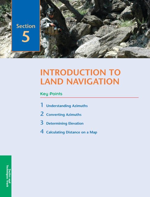
Section<br />
5<br />
INTRODUCTION TO<br />
LAND NAVIGATION<br />
Key Points<br />
1 Understanding Azimuths<br />
2 Converting Azimuths<br />
3 Determining Elevation<br />
4 Calculating Distance on a Map<br />
Tactics and<br />
Techniques Track
<strong>Introduction</strong> <strong>to</strong> <strong>Land</strong> <strong>Navigation</strong> ■ 199<br />
<strong>Introduction</strong><br />
To accomplish your mission, you must be in the right place at the right time. Being in<br />
the right place requires you <strong>to</strong> navigate well. Knowing how <strong>to</strong> read a map is one<br />
thing—knowing how <strong>to</strong> use a map <strong>to</strong> navigate requires that you understand how <strong>to</strong><br />
use azimuths, elevation, and map distance.<br />
In the previous section, you learned how <strong>to</strong> identify and interpret <strong>to</strong>pographic<br />
symbols, colors, con<strong>to</strong>ur lines, and marginal information found on a military map. You<br />
also learned about the military grid reference system and how <strong>to</strong> plot grid coordinates<br />
using a military map and protrac<strong>to</strong>r.<br />
This section will expand your map-reading skills and introduce you <strong>to</strong> how the<br />
military navigates using a map, compass, and protrac<strong>to</strong>r. You will learn what an<br />
azimuth is and how <strong>to</strong> convert azimuths in order <strong>to</strong> navigate using a compass and<br />
map. You will also learn how <strong>to</strong> determine the elevation of the terrain by analyzing the<br />
con<strong>to</strong>ur lines and con<strong>to</strong>ur interval data from the marginal information on a military<br />
map. Lastly, you will learn <strong>to</strong> compute straight-line and road distance using the scale in<br />
the margin of the military map. Coupled with your learning from your orienteering<br />
and map reading lessons, you will have the basic knowledge <strong>to</strong> navigate from one<br />
point <strong>to</strong> another and arrive safely at your destination.<br />
In the following vignette, COL John Zierdt Jr., commander of the 1st Support<br />
Command during the first Gulf War, remembers how a group of Soldiers paid a serious<br />
price when they decided <strong>to</strong> rely on familiarity rather than put in<strong>to</strong> practice basic mapreading<br />
and land-navigation skill required of all Soldiers.<br />
Captured During Desert S<strong>to</strong>rm<br />
The driver had been on a particular route two or three times and thought he<br />
knew where he was going. Then instead of turning left, he kept going straight.<br />
They even saw the water on their right, which was a dead giveaway that they<br />
were going north rather than west. There were two HETs [heavy trucks] following<br />
each other. The guy, the one that was eventually captured, was in the lead<br />
vehicle, and s<strong>to</strong>pped. And the guys behind him said, “You’re going the wrong<br />
way and we need <strong>to</strong> turn around.” He said, “I am not.” He says, “I’m going<br />
straight. You can follow me or turn around if you want.”<br />
So, they kept going straight. The next thing you knew they were in the middle<br />
of a firefight. The second vehicle got turned around in time [and] got out of<br />
there; the [first] vehicle got stuck and didn’t get turned around, and the two of<br />
them got captured.<br />
Department of the <strong>Army</strong>, XVIII Airborne Corps and<br />
US <strong>Army</strong> Center of Military His<strong>to</strong>ry<br />
Tactics and<br />
Techniques Track
200 ■ SECTION 5<br />
Critical Thinking<br />
e<br />
If the drivers of the two vehicles had looked at and oriented their maps, what<br />
might have <strong>to</strong>ld them they were headed in the wrong direction?<br />
What would you have done if you were in the second vehicle? Would you<br />
have continued <strong>to</strong> follow the first vehicle after you decided it was going the<br />
wrong way?<br />
What could you have said over the radio <strong>to</strong> the Soldiers in the first vehicle that<br />
may have triggered in their minds that they were, in fact, going in the wrong<br />
direction?<br />
azimuth<br />
the horizontal angle,<br />
measured clockwise by<br />
degrees or mils between<br />
a reference direction<br />
and the line <strong>to</strong> an<br />
observed or designated<br />
point—there are three<br />
base (reference)<br />
directions or azimuths:<br />
true, grid, and magnetic<br />
azimuth<br />
The terms azimuth and<br />
direction are<br />
interchangeable.<br />
grid azimuth<br />
the angle between grid<br />
north and a line drawn<br />
on the map<br />
Understanding Azimuths<br />
Everything in land navigation begins with an azimuth. An azimuth is a horizontal angle<br />
measured clockwise by degrees or mils between a reference direction and a line <strong>to</strong> an<br />
observed or designated point. There are three base directions or azimuths: true, grid, and<br />
magnetic.<br />
The <strong>Army</strong> uses azimuths <strong>to</strong> express direction. Direction is determined from your<br />
start point, or where you are, outward <strong>to</strong>ward your desired destination, or your intended<br />
target. Because you use north (0 or 360 degrees) as your base line, 270 degrees away from<br />
north will always be due west.<br />
Think of yourself as standing in the middle of a Nebraska cornfield. You are facing<br />
north. The horizon stretches around you in a great 360-degree circle. If you travel an<br />
azimuth of zero degrees—or 360 degrees—or due north—you will wind up in Canada.<br />
If you turn <strong>to</strong> your right and travel on an azimuth of 90 degrees—due east—you will<br />
wind up in the Atlantic Ocean, probably off the coast of New Jersey.<br />
An azimuth of 180 degrees—due south—will take you in<strong>to</strong> Mexico, and an azimuth<br />
of 270 degrees—due west—will take you <strong>to</strong> the Pacific, just off the coast of Northern<br />
California.<br />
Determining a Grid Azimuth Using a Protrac<strong>to</strong>r<br />
There are two ways you can determine an azimuth. You can use a map <strong>to</strong> determine a<br />
grid azimuth, or you can use a compass <strong>to</strong> determine a magnetic azimuth. Regardless of<br />
the technique, you will learn in this chapter how <strong>to</strong> convert a grid azimuth <strong>to</strong> a magnetic<br />
azimuth and a magnetic azimuth <strong>to</strong> a grid azimuth. You will first use a map and learn<br />
how <strong>to</strong> determine a grid azimuth. The steps in this process should be very familiar if you<br />
have ever taken a geometry class.<br />
To begin, select a start point on the map. Mark it as point A. Identify an end point on<br />
your map. Mark it as point B. Using the edge of your protrac<strong>to</strong>r, draw a straight pencil<br />
line between points A and B. The line is your azimuth. Now you must determine the grid<br />
azimuth of that line—the angle between the line and grid north.<br />
When you lay your protrac<strong>to</strong>r down on your map, make sure you place it right side<br />
up; verify this by checking <strong>to</strong> see that the writing on the protrac<strong>to</strong>r is not backward. If your<br />
protrac<strong>to</strong>r is wrong side up, you will get grid azimuths that are 180 degrees off from the
<strong>Introduction</strong> <strong>to</strong> <strong>Land</strong> <strong>Navigation</strong> ■ 201<br />
Although having the<br />
mils scale on the outside<br />
of the protrac<strong>to</strong>r may<br />
seem confusing now,<br />
don’t get in<strong>to</strong> the habit<br />
of cutting the mils scale<br />
off your protrac<strong>to</strong>r. Later<br />
in your military career,<br />
your military<br />
occupational specialty<br />
(MOS) may require you<br />
<strong>to</strong> state azimuths in<br />
mils as well as degrees.<br />
Figure 5.1 <strong>Army</strong> Protrac<strong>to</strong>r (GTA 5-2-12, 1981)<br />
correct grid azimuth. Also, make sure the 0- or 360-degree mark of your protrac<strong>to</strong>r is<br />
<strong>to</strong>ward the <strong>to</strong>p (or north) of your map, and make sure the 90-degree mark is <strong>to</strong>ward the<br />
right (or east) of your map. If you place your protrac<strong>to</strong>r down incorrectly on your map, the<br />
grid azimuth that you determine will be a minimum of 90 degrees off and as much as 270<br />
degrees off the actual azimuth.<br />
Follow these three steps <strong>to</strong> determine your grid azimuth from the arbitrary points A<br />
and B (Figure 5.2):<br />
1. Place the index of your protrac<strong>to</strong>r (the place where the etched vertical line and<br />
the etched horizontal line meet) at the point where the line you drew on your<br />
map crosses a vertical, north-south grid line.<br />
2. Keeping the index at this point, line up the 0-<strong>to</strong>-180-degree line, or base line, of<br />
the protrac<strong>to</strong>r on the vertical, north-south grid line.<br />
3. Follow your line outward <strong>to</strong> the degree scale of your protrac<strong>to</strong>r. Read the value<br />
of the angle from the protrac<strong>to</strong>r. This is your grid azimuth from point A <strong>to</strong> point<br />
B expressed in degrees.<br />
Next, you will plot an azimuth from a known point on a map. Imagine you receive an<br />
order <strong>to</strong> move from your current position in a given direction. Plotting the azimuth on<br />
your map will allow you <strong>to</strong> see the terrain and objects you will need <strong>to</strong> navigate through<br />
along the entire length of your azimuth. The steps are as follows:
202 ■ SECTION 5<br />
Figure 5.2<br />
Measuring an Azimuth<br />
This is the same method<br />
you will use <strong>to</strong><br />
determine the grid<br />
azimuth between any<br />
two points on the map.<br />
1. Place your protrac<strong>to</strong>r on the map with the index mark at the center of the<br />
known point and the base line parallel <strong>to</strong> a vertical, north-south grid line.<br />
2. Using your pencil, make a small tick mark on the map at the edge of the<br />
protrac<strong>to</strong>r at the desired azimuth. Remember that your protrac<strong>to</strong>r will have<br />
degrees on the inner scale and mils on the outer scale. Ensure the tick mark on<br />
the map is beside the desired azimuth in degrees and not mils.<br />
3. Lift and reposition the protrac<strong>to</strong>r so you can use its side as a straightedge. Draw<br />
a line connecting the known point and the tick mark on the map. This is your<br />
grid direction line—your azimuth.
<strong>Introduction</strong> <strong>to</strong> <strong>Land</strong> <strong>Navigation</strong> ■ 203<br />
Determining a Back Azimuth<br />
A back azimuth is simply the opposite direction <strong>to</strong> your azimuth. A simple example is<br />
when you get on the interstate going north when you wanted <strong>to</strong> go south. At the next<br />
exit, you get off the interstate, turn around, and get back on the interstate going south. You<br />
just <strong>to</strong>ok a back azimuth, or in slang, you just “did a 180.”<br />
To compute a back azimuth from an azimuth, simply add or subtract 180 degrees <strong>to</strong><br />
or from your original azimuth. Remember that a circle has 360 degrees, so if your azimuth<br />
is greater than 180 degrees, adding 180 degrees <strong>to</strong> determine your back azimuth will give<br />
you an azimuth that is more than 360 degrees. For example, if your azimuth were 200<br />
degrees, adding 180 degrees would result in a back azimuth of 380 degrees, whereas<br />
subtracting 180 degrees would result in a back azimuth of 20 degrees. The back azimuth<br />
380 degrees is obviously greater than the number of degrees in a circle—20 degrees greater.<br />
Sure, you could subtract 360 degrees from 380 degrees and still get the same correct back<br />
azimuth of 20 degrees. But this simply adds another step <strong>to</strong> the process. So, subtracting<br />
180 degrees from azimuths greater than 180 degrees simplifies determining back azimuths.<br />
back azimuth<br />
the opposite direction of<br />
an azimuth—<strong>to</strong> obtain<br />
a back azimuth from an<br />
azimuth, add 180<br />
degrees if the azimuth is<br />
180 degrees or less, or<br />
subtract 180 degrees if<br />
the azimuth is 180<br />
degrees or more<br />
Determining a Magnetic Azimuth <strong>to</strong> an Object<br />
A magnetic azimuth is an azimuth determined using magnetic instruments, such as a<br />
compass. The <strong>Army</strong> uses two types of compasses: the M2 compass and the lensatic compass.<br />
Soldiers use the M2 compass primarily for positioning indirect fire weapons such as mortars.<br />
The lensatic compass, pictured in Figure 5.3, is the compass the <strong>Army</strong> uses for land<br />
navigation.<br />
To determine a magnetic azimuth using a compass:<br />
1. Open your compass <strong>to</strong> its fullest so the cover forms a straightedge with the base.<br />
Move the lens (the rear sight) <strong>to</strong> the rearmost position. This allows the dial <strong>to</strong><br />
float freely.<br />
2. Place your thumb through the thumb loop, form a steady base with your third<br />
and fourth fingers, and extend your index finger along the side of the compass.<br />
3. Place the thumb of your other hand between the lens (rear sight) and the bezel<br />
ring; extend your index finger along the remaining side of the compass, and your<br />
remaining fingers around the fingers of your other hand. Tuck your elbows in<strong>to</strong><br />
your sides. This will place the compass between your chin and your belt.<br />
4. Turn your body <strong>to</strong>ward the object that you wish <strong>to</strong> get an azimuth <strong>to</strong>, pointing<br />
your compass cover directly at the object.<br />
5. Look down and read the azimuth from beneath the fixed black index line on the<br />
compass face.<br />
Critical Thinking<br />
e<br />
1. Why is it important for you <strong>to</strong> understand how <strong>to</strong> determine a back azimuth?<br />
2. When would you use a back azimuth?
204 ■ SECTION 5<br />
Figure 5.3<br />
Centerhold Technique With a<br />
Lensatic Compass<br />
Figure 5.4<br />
True, Magnetic, and Grid North<br />
Shooting an Azimuth with a Compass<br />
When you already know the magnetic azimuth that you want <strong>to</strong> navigate along, you follow<br />
the above steps, but reverse steps 4 and 5. You look down at the compass bezel and slowly<br />
turn your body until you see the azimuth you wish <strong>to</strong> take. Once you see your azimuth on<br />
the bezel, look up, and identify an easily recognizable object off in the distance that is in line<br />
with your azimuth. Once you have identified the object on your azimuth, you can put<br />
your compass away and move <strong>to</strong> that object. As long as you continue <strong>to</strong> move <strong>to</strong> your<br />
identified object, you will be on your desired azimuth. This method is known as “shooting<br />
an azimuth.”<br />
declination diagram<br />
the chart in the map<br />
legend that tells you the<br />
differences in angle<br />
between true north, grid<br />
north, and magnetic<br />
north<br />
Converting Azimuths<br />
Two problems complicate your easy use of a map and compass:<br />
First, the surface of the earth is curved, while the surface of your map is flat. This creates<br />
problems between what your map shows as north (grid north) and what really is north<br />
(true north).<br />
Second, the earth’s magnetic pole is not the same as the earth’s axis. This creates a<br />
difference between what your compass shows as north (magnetic north) and what really<br />
is north (true north).<br />
Your map contains information <strong>to</strong> help you overcome these problems. The declination<br />
diagram in your map’s legend gives you the information you need <strong>to</strong> compensate for the<br />
differences—declination—between grid north, true north, and magnetic north.<br />
The declination diagram (Figure 5.4) shows you the difference in angle between any<br />
of these norths. Since you will navigate with a magnetic compass and a grid map, your<br />
primary concern is the difference between grid north and magnetic north. The difference<br />
between grid north and magnetic north is known as the G-M angle (grid-magnetic angle).
<strong>Introduction</strong> <strong>to</strong> <strong>Land</strong> <strong>Navigation</strong> ■ 205<br />
Figure 5.5<br />
Map Declination Diagram<br />
The G-M angle will be shown in the declination diagram and will be expressed in<br />
degrees. The G-M angle will either be <strong>to</strong> the west of grid north (westerly G-M angle) or<br />
<strong>to</strong> the east of grid north (easterly G-M angle). To reduce the confusion of converting easterly<br />
and westerly G-M angles from grid <strong>to</strong> magnetic or magnetic <strong>to</strong> grid, the mapmakers now<br />
include easy-<strong>to</strong>-understand instructions on the declination diagram so you can quickly<br />
convert azimuths without remembering formulas (Figure 5.5).<br />
The three vec<strong>to</strong>rs that make up the declination diagram (true north, grid north, and<br />
magnetic north) are not drawn <strong>to</strong> scale. Use the written value for the G-M angle and do<br />
not try <strong>to</strong> measure the vec<strong>to</strong>rs <strong>to</strong> determine the G-M angle.<br />
Most military maps will display the declination diagram in the lower margin. Some<br />
maps may not display the declination diagram and will only list the declination information<br />
as a note in the map margin.<br />
Adjusting for the Grid-Magnetic (G-M) Angle<br />
The G-M angle value is the size of the angle between grid north and magnetic north. You<br />
will see it as an arc, indicated by a dashed line, connecting the grid-north and magneticnorth<br />
vec<strong>to</strong>rs.<br />
The G-M angle is important because if you don’t adjust for the G-M angle, your grid<br />
azimuth translated from your map <strong>to</strong> your compass will be wrong by the size of the angle<br />
and vice versa. For example, if your G-M angle is 8 degrees and you don’t adjust for that<br />
angle, your grid or magnetic azimuth will be off by 8 degrees. The farther you move away<br />
from your start point on your incorrect azimuth, the farther off you will be from your<br />
objective. The angular error increases the farther you move. Not using the G-M angle when<br />
converting from a grid azimuth <strong>to</strong> a magnetic azimuth can cause you <strong>to</strong> miss your objective.<br />
Likewise, if you forget <strong>to</strong> use the G-M angle when you convert a magnetic azimuth <strong>to</strong> a<br />
grid azimuth, you will plot the wrong azimuth on your map. This could result in passing<br />
on incorrect information or calling in inaccurate indirect fire missions.<br />
Look at the notes that accompany the G-M angle diagram (Figure 5.5). One note tells<br />
you how <strong>to</strong> convert your magnetic azimuth <strong>to</strong> a grid azimuth; another tells you how <strong>to</strong><br />
convert your grid azimuth <strong>to</strong> a magnetic azimuth.
206 ■ SECTION 5<br />
A typical note may read “To convert a magnetic azimuth <strong>to</strong> grid azimuth, subtract<br />
G-M angle.” If you have a magnetic azimuth of 270 degrees, and the G-M angle is 8 degrees,<br />
your grid azimuth will be 262 degrees.<br />
The conversion (whether <strong>to</strong> add or subtract) depends on whether your map has an<br />
easterly or westerly G-M angle. If your magnetic north is <strong>to</strong> the right (east) of the grid<br />
north, then your map has an easterly G-M angle. If your magnetic north is <strong>to</strong> the left (west)<br />
of the grid north, then your map has a westerly G-M angle.<br />
You will learn more about azimuths and land navigation as you progress through<br />
<strong>ROTC</strong>. By the end of your MSL III year, you must master land navigation in order <strong>to</strong> succeed<br />
at the Leader Development and Assessment Course (LDAC), which you will attend at<br />
Fort Lewis, Wash., after your MSL III year.<br />
Determining Elevation<br />
You can determine the elevation of any location on your map without any special equipment<br />
using two things on your map that you learned about in the previous Map Reading<br />
section—con<strong>to</strong>ur lines and the con<strong>to</strong>ur interval. Before you can determine the elevation<br />
of any point on your map, you must first know the con<strong>to</strong>ur interval for the map you are<br />
using. As you read previously, you can find the con<strong>to</strong>ur interval in the margin of your<br />
map—usually in the middle of the lower margin. Recall that the con<strong>to</strong>ur interval is a<br />
measurement of the vertical distance between adjacent con<strong>to</strong>ur lines.<br />
Refer <strong>to</strong> Figure 5.7 <strong>to</strong> learn how <strong>to</strong> determine the specific elevation of a point on<br />
a map:<br />
1. Identify the con<strong>to</strong>ur interval and the unit of measure used (feet, meters, or<br />
yards) from your map’s marginal information at Figure 5.6 (most military maps<br />
use meters).<br />
Using the map example at Figure 5.7, if you wanted <strong>to</strong> determine the elevation<br />
<strong>to</strong> point A, you would find the numbered index con<strong>to</strong>ur line nearest point A. In<br />
Figure 5.7, the closest numbered con<strong>to</strong>ur line <strong>to</strong> point A is the 500-meter<br />
con<strong>to</strong>ur interval.<br />
Determine if point A is above (higher in elevation) the 500-meter con<strong>to</strong>ur line,<br />
or if point A is below (lower in elevation) than the 500-meter line. Since point A<br />
lies between the 500-meter con<strong>to</strong>ur line and the 600-meter con<strong>to</strong>ur line, moving<br />
from the closest con<strong>to</strong>ur line (500-meter) <strong>to</strong> point A would be traveling uphill <strong>to</strong><br />
a higher elevation.<br />
2. Determine the elevation of point A by starting at the index con<strong>to</strong>ur line<br />
numbered 500 and counting the number of intermediate con<strong>to</strong>ur lines (the<br />
unmarked con<strong>to</strong>ur lines) <strong>to</strong> point A.<br />
Point A is on the second intermediate con<strong>to</strong>ur line above the 500-meter index<br />
con<strong>to</strong>ur line. Since the con<strong>to</strong>ur interval is 20 meters (Figure 5.6), each<br />
intermediate con<strong>to</strong>ur line crossed <strong>to</strong> get <strong>to</strong> point A adds 20 meters <strong>to</strong> the 500-<br />
meter index con<strong>to</strong>ur line. The elevation of point A is 540 meters.<br />
3. Determine the elevation of point B by going <strong>to</strong> the nearest index con<strong>to</strong>ur line. In<br />
this case, it is the upper index con<strong>to</strong>ur line, numbered 600. Point B is located on the<br />
intermediate con<strong>to</strong>ur line immediately below the 600-meter index con<strong>to</strong>ur line.<br />
Therefore, point B is located at an elevation of 580 meters. Remember, if you are<br />
increasing elevation, add the con<strong>to</strong>ur interval <strong>to</strong> the nearest index con<strong>to</strong>ur line.<br />
If you are decreasing elevation, subtract the con<strong>to</strong>ur interval from the nearest<br />
index con<strong>to</strong>ur line.
<strong>Introduction</strong> <strong>to</strong> <strong>Land</strong> <strong>Navigation</strong> ■ 207<br />
Figure 5.6<br />
Example of a Con<strong>to</strong>ur Interval Note<br />
Figure 5.7<br />
Points on Con<strong>to</strong>ur Lines<br />
Critical Thinking<br />
e<br />
Why is it important for you <strong>to</strong> know how <strong>to</strong> determine elevation on a military<br />
map? Think about the azimuth you will plot on your map in order <strong>to</strong> travel from<br />
point A <strong>to</strong> point B. How will knowing elevation help you when navigating from<br />
point A <strong>to</strong> point B? Can knowing the elevation help you decide which azimuths<br />
or routes <strong>to</strong> take <strong>to</strong> your destination?
208 ■ SECTION 5<br />
4. Estimate the elevation of the hill<strong>to</strong>p, point C, by adding one-half of the con<strong>to</strong>ur<br />
interval <strong>to</strong> the elevation of the last con<strong>to</strong>ur line. In this example, the last con<strong>to</strong>ur<br />
line before the hill<strong>to</strong>p is an index con<strong>to</strong>ur line numbered 600. Add one-half the<br />
con<strong>to</strong>ur interval, 10 meters, <strong>to</strong> the index con<strong>to</strong>ur line. The elevation of the<br />
hill<strong>to</strong>p would be 610 meters. You use the same process <strong>to</strong> estimate the elevation<br />
of a depression, except you subtract half of the con<strong>to</strong>ur interval <strong>to</strong> estimate the<br />
elevation at the bot<strong>to</strong>m of the depression.<br />
Calculating Distance on a Map<br />
Now you know how <strong>to</strong> plot and determine azimuths on your map, and you understand<br />
how <strong>to</strong> determine elevation on your map or along your plotted azimuth. But how far is it<br />
from your start point <strong>to</strong> your destination? The marginal information on your map allows<br />
you <strong>to</strong> determine both straight-line distance and road distance. You can use the graphic<br />
scale—located in the lower center portion of the map margin—as a ruler <strong>to</strong> convert<br />
distances on the map <strong>to</strong> distances on the ground (Figure 5.8).<br />
The graphic scale is divided in<strong>to</strong> two parts. To the right of the zero, the scale is marked<br />
in full units of measure and is called the primary scale. To the left of the zero, the scale is<br />
divided in<strong>to</strong> tenths and is called the extension scale.<br />
Most maps have three or more graphic scales, each with a different unit of measure,<br />
such as meters, yards, statute miles, and nautical miles. When you use the graphic scale,<br />
be sure that you use the appropriate unit of measure.<br />
Straight-Line Distance<br />
To calculate the straight-line distance between two points on your map:<br />
1. Lay a straight-edged piece of paper on the map so the edge of your paper<br />
<strong>to</strong>uches both points and extends past them.<br />
2. Make a tick mark on the edge of the paper at each point (Figure 5.9).<br />
3. Then move your paper <strong>to</strong> the graphic bar scale, and use the scale <strong>to</strong> measure the<br />
distance between the two points. Note that you should align the tick mark on the<br />
right with a printed number in the primary scale so that the left tick mark falls<br />
within the extension scale (Figure 5.10).<br />
Figure 5.8<br />
Using a Graphic (Bar) Scale
<strong>Introduction</strong> <strong>to</strong> <strong>Land</strong> <strong>Navigation</strong> ■ 209<br />
Figure 5.9<br />
Transferring Map Distance <strong>to</strong> Paper Strip<br />
Figure 5.10<br />
Measuring Straight-Line Map Distance
210 ■ SECTION 5<br />
The more tick marks<br />
you make when<br />
measuring your curved<br />
route, the more<br />
accurate your final<br />
distance will be. This is<br />
especially true when<br />
measuring along curves.<br />
Curved-Line Distance<br />
To measure the distance along a curved route, such as a road, trail, waterway, or other<br />
curved line:<br />
Put a straight-edged piece of paper on your map with the edge next <strong>to</strong> your starting<br />
point. Place a tick mark on the paper and on your map.<br />
Line up the straight edge of the paper with the straight portion of the curved route<br />
you are measuring. Make a tick mark on both map and paper when the edge of the paper<br />
leaves the straight portion of the line you’re measuring. (See View A in Figure 5.11.)<br />
Pivot the paper until another straight portion of the curved line lines up with the<br />
edge of the paper. Continue in this manner until you have completed the distance you<br />
want <strong>to</strong> measure. (See View B in Figure 5.11. Notice the number of small ticks on the edge<br />
of the paper and that the last is labeled tick mark B.)<br />
Move the paper <strong>to</strong> the graphic scale <strong>to</strong> determine the ground distance. The only tick<br />
marks you need <strong>to</strong> measure are tick marks A and B. (See View C in Figure 5.11.)<br />
In order <strong>to</strong> maintain accuracy when measuring curved distance, it is important <strong>to</strong> keep<br />
the straight edge of your paper on the same side of the curve you are measuring. If you<br />
start off measuring a curved road on one side of that road, then keep your paper on that<br />
side of the road and mark all of your tick marks on that same side of the road. Do not cross<br />
over and start making tick marks on the opposite side of the road.
<strong>Introduction</strong> <strong>to</strong> <strong>Land</strong> <strong>Navigation</strong> ■ 211<br />
Figure 5.11<br />
Measuring a Curved Line
212 ■ SECTION 5<br />
e<br />
CONCLUSION<br />
You are a Cadet now. In the not-<strong>to</strong>o-distant future, you may be an <strong>Army</strong> second<br />
lieutenant leading a pla<strong>to</strong>on. Perhaps, in the distant future, you will be a<br />
lieutenant colonel commanding a battalion, a colonel commanding a brigade, or<br />
even a major general commanding a division. Whatever your position and rank,<br />
you will always need <strong>to</strong> get your Soldiers from one point <strong>to</strong> another. If you can’t<br />
do so, you endanger your mission and perhaps the lives of your Soldiers.<br />
It’s impossible <strong>to</strong> overemphasize the importance of map reading and land<br />
navigation. They are critical leadership skills. They are also perishable skills—they<br />
require constant practice and review, regardless of a Soldier’s rank or experience.<br />
Start now <strong>to</strong> develop your expertise and work <strong>to</strong> keep your skills honed and at<br />
the ready.<br />
Learning Assessment<br />
1. What is an azimuth?<br />
2. Explain how <strong>to</strong> determine a grid azimuth.<br />
3. Explain how <strong>to</strong> determine a magnetic azimuth.<br />
4. Explain the differences between the three norths.<br />
5. Explain how <strong>to</strong> use the G-M angle <strong>to</strong> convert grid and magnetic azimuth.<br />
6. What is a con<strong>to</strong>ur interval?<br />
7. Explain how <strong>to</strong> determine elevation on a map.<br />
8. Explain how <strong>to</strong> measure the straight line and curved distance between two<br />
points on a map.
<strong>Introduction</strong> <strong>to</strong> <strong>Land</strong> <strong>Navigation</strong> ■ 213<br />
Key Words<br />
azimuth<br />
grid azimuth<br />
back azimuth<br />
declination diagram<br />
References<br />
Field Manual 3-21.8, The Infantry Rifle Pla<strong>to</strong>on and Squad. 28 March 2007.<br />
Field Manual 3-25.26, Map Reading and <strong>Land</strong> <strong>Navigation</strong>. 18 January 2005.<br />
Department of the <strong>Army</strong>, XVIII Airborne Corps and US <strong>Army</strong> Center of Military<br />
His<strong>to</strong>ry. (10 June 1991). Operations Desert Shield and Desert S<strong>to</strong>rm. Oral His<strong>to</strong>ry<br />
Interview DSIT AE 108. Fort Bragg, NC, and Washing<strong>to</strong>n, DC. Retrieved 8 July 2005<br />
from http://www.army.mil/cmh-pg/documents/swa/dsit/DSIT108.htm


