Oceanview Renovation
Oceanview Renovation
Oceanview Renovation

Create successful ePaper yourself
Turn your PDF publications into a flip-book with our unique Google optimized e-Paper software.
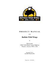
PROJECT MANUAL<br />
for<br />
<strong>Oceanview</strong> <strong>Renovation</strong><br />
Clearwater, Florida<br />
ISSUED FOR CONSTRUCTION<br />
April 26, 2011<br />
Owner: Church of Scientology Religious Trust, 503<br />
Cleveland Street, Clearwater, FL 33755<br />
Civil and Landscape: Kimley Horn and Associates, 2601<br />
Cattlemen Road, Suite 500, Sarasota, FL 34232<br />
Architect: Gensler, 101 Marietta Street NW, Suite 3000,<br />
Atlanta, GA 30303<br />
Structural Engineer: Mohan Engineering, 13630 58 th<br />
Street North, Suite 107, Clearwater, FL 33760<br />
Roofing Consultant: Roof Engineering Associates, 500<br />
County Road One, PO Box 549, Palm Harbor, FL 34684<br />
Elevator Consultant: Lerch Bates, 2300 Glades Road,<br />
Suite 230 W, Glades Twin Plaza West, Boca Raton, FL<br />
33431<br />
Pool Consultant: Gardner Collins, 1268 Rogers Street,<br />
Clearwater, FL 33756<br />
Mechanical, Plumbing and Fire Protection Engineers:<br />
Stewart Engineering Consultants, Inc., 1859 Northgate<br />
Blvd., Sarasota, FL 34234<br />
Electrical Engineer: KBA Engineering, Inc., 201 Flagship<br />
Drive, Suite E, Lutz, FL 33549
Gensler April 26, 2011 <strong>Oceanview</strong> <strong>Renovation</strong><br />
13.7123.000 Issued for Construction Clearwater, Florida<br />
TABLE OF CONTENTS<br />
PROCUREMENT AND CONTRACTING REQUIREMENTS GROUP<br />
DIVISION 00 – PROCUREMENT AND CONTRACTING REQUIREMENTS<br />
INTRODUCTORY INFORMATION<br />
Date Section No. Title<br />
00 01 01 Project Title Page<br />
00 01 10 Table Of Contents<br />
PROCUREMENT REQUIREMENTS<br />
Date Section No. Title<br />
00 21 13 Instructions To Bidders<br />
00 21 16 Instructions To Proposers<br />
00 31 32 Geotechnical Data<br />
00 41 00 Bid Form<br />
00 42 00 Proposal Form<br />
CONTRACTING REQUIREMENTS<br />
Date Section No. Title<br />
00 52 00 Agreement Form<br />
00 61 00 Bonds<br />
00 72 00 General Conditions<br />
00 73 00 Supplementary Conditions<br />
00 91 13 Addenda<br />
TABLE OF CONTENTS 00 01 10 - 1<br />
Copyright 2011 Gensler
Gensler April 26, 2011 <strong>Oceanview</strong> <strong>Renovation</strong><br />
13.7123.000 Issued for Construction Clearwater, Florida<br />
SPECIFICATIONS GROUP<br />
GENERAL REQUIREMENTS SUBGROUP<br />
DIVISION 01 - GENERAL REQUIREMENTS<br />
Date Section No. Title<br />
01 10 00 Summary<br />
01 14 00 Work Restrictions<br />
01 23 00 Alternates<br />
01 25 00 Substitution Procedures<br />
01 25 00.01 Substitution Request Form<br />
01 26 00 Contract Modification Procedures<br />
01 26 00.01 Bulletin Form<br />
01 26 00.02 Change Order Form<br />
01 26 13 Requests for Interpretation (RFIs)<br />
01 26 13.01 Request for Interpretation Form<br />
01 29 00 Payment Procedures<br />
01 31 00 Project Management and Coordination<br />
01 32 00 Construction Progress Documentation<br />
01 33 00 Submittal Procedures<br />
01 33 00.01 Data Transfer Agreement<br />
01 33 10 Coordination Drawings<br />
01 40 00 Quality Requirements<br />
01 42 00 References<br />
01 50 00 Temporary Facilities And Controls<br />
01 60 00 Product Requirements<br />
01 73 00 Execution<br />
01 73 29 Cutting And Patching<br />
01 77 00 Closeout Procedures<br />
01 77 00.01 Closeout Procedure Form<br />
FACILITY CONSTRUCTION SUBGROUP<br />
DIVISION 02 – EXISTING CONDITIONS<br />
Date Section No. Title<br />
02 22 00 Site Preparation, Excavation, and Earthwork for Foundations –<br />
specification as provided by Mohan Engineering<br />
02 41 19 Selective Structure Demolition<br />
TABLE OF CONTENTS 00 01 10 - 2<br />
Copyright 2011 Gensler
Gensler April 26, 2011 <strong>Oceanview</strong> <strong>Renovation</strong><br />
13.7123.000 Issued for Construction Clearwater, Florida<br />
DIVISION 03 – CONCRETE<br />
Date Section No. Title<br />
03 30 00 Cast-In-Place Concrete Foundations – specification as provided by<br />
Mohan Engineering<br />
03 54 16 Hydraulic Cement Underlayment<br />
DIVISION 04 – MASONRY<br />
Date Section No. Title<br />
04 20 00 Unit Masonry – specification as provided by Mohan Engineering<br />
DIVISION 05 – METALS<br />
Date Section No. Title<br />
05 04 00 Hot Dip Galvanizing – specification as provided by Mohan<br />
Engineering<br />
05 12 00 Structural Steel – specification as provided by Mohan Engineering<br />
05 21 00 Steel Joists – specification as provided by Mohan Engineering<br />
05 31 00 Steel Deck – specification as provided by Mohan Engineering<br />
05 40 00 Structural Studs - specification as provided by Mohan Engineering<br />
05 50 00 Metal Fabrications<br />
05 52 13 Pipe and Tube Railings<br />
DIVISION 06 – WOOD, PLASTICS, AND COMPOSITES<br />
Date Section No. Title<br />
06 10 53 Miscellaneous Rough<br />
06 16 00 Sheathing<br />
06 40 23 Interior Architectural Woodwork<br />
DIVISION 07 – THERMAL AND MOISTURE PROTECTION<br />
Date Section No. Title<br />
07 01 50.19 Preparation for Re-Roofing<br />
07 19 00 Water Repellents<br />
07 21 00 Thermal Insulation<br />
07 25 00 Weather Barriers<br />
07 54 19 Polyvinyl-Chloride (PVC) Roofing<br />
07 62 00 Sheet Metal Flashing and Trim<br />
07 71 00 Roof Specialties<br />
07 71 29 Manufactured Roof Expansion Joints<br />
07 72 00 Roof Accessories<br />
07 81 00 Applied Fireproofing<br />
07 84 13 Penetration Firestopping<br />
07 84 46 Fire-Resistive Joint Systems<br />
07 92 00 Joint Sealants<br />
07 95 00 Expansion Control<br />
TABLE OF CONTENTS 00 01 10 - 3<br />
Copyright 2011 Gensler
Gensler April 26, 2011 <strong>Oceanview</strong> <strong>Renovation</strong><br />
13.7123.000 Issued for Construction Clearwater, Florida<br />
DIVISION 08 – OPENINGS<br />
Date Section No. Title<br />
08 11 13 Hollow Metal Doors and Frames<br />
08 12 16 Aluminum Doors and Frames<br />
08 14 16 Flush Wood Doors<br />
08 31 00 Access Doors And Frames<br />
08 32 13 Sliding Aluminum-Framed Glass<br />
08 41 13 Aluminum-Framed Entrances and Storefronts<br />
08 51 13 Aluminum Windows<br />
08 71 00 Door Hardware<br />
08 80 00 Glazing<br />
DIVISION 09 – FINISHES<br />
Date Section No. Title<br />
09 24 00 Portland Cement Plastering<br />
09 29 00 Gypsum Board<br />
09 30 00 Tiling<br />
09 30 33 Stone Tiling<br />
09 51 13 Acoustical Panel Ceilings<br />
09 61 23 Concrete Flooring Treatment<br />
09 64 00 Wood Flooring<br />
09 65 13 Resilient Base and Accessories<br />
09 65 19 Resilient Tile Flooring<br />
09 91 13 Exterior Painting<br />
09 91 23 Interior Painting<br />
09 96 53 Elastomeric Coatings<br />
DIVISION 10 – SPECIALTIES<br />
Date Section No. Title<br />
10 28 00 Toilet, Bath, and Laundry Accessories<br />
10 44 00 Fire-Protection Specialties<br />
DIVISION 11 – EQUIPMENT<br />
Date Section No. Title<br />
11 31 00 Pantry and Residential Appliances<br />
DIVISION 12 – FURNISHINGS<br />
Date Section No. Title<br />
12 36 40 Stone Countertops<br />
TABLE OF CONTENTS 00 01 10 - 4<br />
Copyright 2011 Gensler
Gensler April 26, 2011 <strong>Oceanview</strong> <strong>Renovation</strong><br />
13.7123.000 Issued for Construction Clearwater, Florida<br />
DIVISION 13 - SPECIAL CONSTRUCTION<br />
Date Section No. Title<br />
NOT APPLICABLE for THIS PROJECT<br />
DIVISION 14 – CONVEYING EQUIPMENT<br />
Date Section No. Title<br />
DOCUMENTATION TO BE PROVIDED BY CONSULTANT<br />
DIVISIONS 15 through 19 – Reserved<br />
Date Section No. Title<br />
NOT APPLICABLE for THIS PROJECT<br />
TABLE OF CONTENTS 00 01 10 - 5<br />
Copyright 2011 Gensler
Gensler April 26, 2011 <strong>Oceanview</strong> <strong>Renovation</strong><br />
13.7123.000 Issued for Construction Clearwater, Florida<br />
FACILITY SERVICES SUBGROUP<br />
DIVISION 20 – Reserved<br />
DIVISION 21 – FIRE SUPPRESSION - REFER TO FIRE SUPPRESSION SHEET<br />
SPECIFICATIONS<br />
DIVISION 22 – PLUMBING<br />
Date Section No. Title<br />
22 05 00 Common Work Results for Plumbing<br />
22 05 16 Expansion Fittings and Loops for Plumbing Piping<br />
22 05 19 Meters and Gages for Plumbing Piping<br />
22 05 23 General Duty Valves for Plumbing Piping<br />
22 05 29 Hangers and Supports for Plumbing Piping and Equipment<br />
22 05 42 Plumbing Pumps<br />
22 05 53 Identification for Plumbing Piping and Equipment<br />
22 07 00 Plumbing Insulation<br />
22 11 13 Facility Water Distribution Piping<br />
22 11 16 Domestic Water Piping<br />
22 11 19 Domestic Water Piping Specialties<br />
22 11 25 Natural Gas Systems<br />
22 13 16 Sanitary Waste and Vent Piping<br />
22 14 13 Facility Storm Drainage Piping<br />
22 33 00 Electric Domestic Water Heaters<br />
22 40 00 Plumbing Fixtures<br />
DIVISION 23 – HEATING, VENTILATING, AND AIR CONDITIONING<br />
Date Section No. Title<br />
23 05 00 Basic Mechanical Requirements<br />
23 05 12 Mechanical Related Work<br />
23 05 13 Electrical Provisions of Mechanical Work<br />
23 05 16 Expansion Compensation<br />
23 05 19 Meters and Gages<br />
23 05 23 Valves<br />
23 05 29 Hangers and Supports for HVAC Piping and Equipment<br />
23 05 48 Vibration Control<br />
23 05 53 Mechanical Identification<br />
23 05 93 Testing, Adjusting and Balancing<br />
23 07 00 Mechanical Insulation<br />
23 09 15 Variable Frequency Drives<br />
23 21 13 Hydronic Piping Systems<br />
23 21 16 Piping Specialties<br />
23 21 23 HVAC Pumps<br />
23 31 12 Phenolic Foam Ductwork<br />
23 31 13 Metal Ductwork<br />
23 33 00 Ductwork Accessories<br />
23 37 00 Air Oulets and Inlets<br />
TABLE OF CONTENTS 00 01 10 - 6<br />
Copyright 2011 Gensler
Gensler April 26, 2011 <strong>Oceanview</strong> <strong>Renovation</strong><br />
13.7123.000 Issued for Construction Clearwater, Florida<br />
23 64 22 Air Cooled Scroll Chillers (70-Tons or Greater)<br />
23 82 15 Air Handling Units (Chilled Water)<br />
DIVISION 24 – Reserved<br />
DIVISION 25 – INTEGRATED AUTOMATION<br />
Date Section No. Title<br />
25 09 23 Direct Digital Control System for HVAC<br />
DIVISION 26 – ELECTRICAL<br />
Date Section No. Title<br />
26 01 00 Basic Electrical Requirements<br />
26 05 19 Low Voltage Electrical Power Conductors and Cables<br />
26 05 20 Electrical Connections for Equipment<br />
26 05 26 Grounds and Bonding for Electrical Systems<br />
26 05 29 Hangers and Supports for Electrical Systems<br />
26 05 33 Raceways and Boxes for Electrical Systems<br />
26 05 53 Identification for Electrical Systems<br />
26 24 16 Panelboards<br />
26 27 26 Wiring Devices<br />
26 28 16 Enclosed Switches and Circuit Breakers<br />
26 29 13 Motor Starters<br />
26 32 13 Engine Generators<br />
26 36 00 Transfer Switches<br />
26 41 13 Lighting Protection for Structures<br />
26 43 13 Transient Voltage Suppression for Low Voltage Electrical Power<br />
Circuits<br />
26 51 00 Interior Lighting<br />
DIVISION 27 – COMMUNICATIONS<br />
Date Section No. Title<br />
27 11 00 Telephone and Data Systems<br />
TABLE OF CONTENTS 00 01 10 - 7<br />
Copyright 2011 Gensler
Gensler April 26, 2011 <strong>Oceanview</strong> <strong>Renovation</strong><br />
13.7123.000 Issued for Construction Clearwater, Florida<br />
DIVISION 28 – ELECTRONIC SAFETY AND SECURITY<br />
Date Section No. Title<br />
28 31 12 Fire Alarm Systems<br />
DIVISION 29 – Reserved<br />
SITE AND INFRASTRUCTURE SUBGROUP – REFER TO CIVIL AND LANDSCAPE SHEET<br />
SPECIFICATIONS<br />
DIVISION 30 – Reserved<br />
DIVISION 31 – EARTHWORK<br />
DIVISION 32 – EXTERIOR IMPROVEMENTS<br />
DIVISION 33 – UTILITIES<br />
DIVISION 34 – TRANSPORTATION<br />
DIVISION 35 – WATERWAY AND MARINE CONSTRUCTION<br />
DIVISIONS 36 through 39 – Reserved<br />
END OF TABLE OF CONTENTS<br />
TABLE OF CONTENTS 00 01 10 - 8<br />
Copyright 2011 Gensler
Gensler April 26, 2011 <strong>Oceanview</strong> <strong>Renovation</strong><br />
13.7123.000 Issued for Construction Clearwater, Florida<br />
SECTION 00 52 00 – AGREEMENT FORM<br />
PART 1 - GENERAL<br />
1.1 The Agreement Form will be the Standard Form of Agreement between the Owner and<br />
Contractor as published by the American Institute of Architect (AIA), Document [A101-1987]<br />
[A101-1997] [A111-1987] [A111-1997].<br />
1.2 The Agreement Form will be in the form as attached to this Section for information.<br />
PART 2 - PRODUCTS (Not Used)<br />
PART 3 - EXECUTION (Not Used)<br />
END OF SECTION 00 52 00<br />
AGREEMENT FORM 00 52 00 - 1<br />
Copyright 2011 Gensler
Gensler April 26, 2011 <strong>Oceanview</strong> <strong>Renovation</strong><br />
13.7123.000 Issued for Construction Clearwater, Florida<br />
SECTION 00 61 00 – BONDS<br />
1.1 Security Bonds: Submit a Performance Bond and a Payment Bond, AIA Document A312 that<br />
is included in these Specifications by reference as if written out in full. Copies of this document<br />
may be examined at the office of the Architect or purchased from the American Institute of<br />
Architects.<br />
END OF SECTION 00 61 00<br />
BONDS 00 61 00 - 1<br />
Copyright 2011 Gensler
Gensler April 26, 2011 <strong>Oceanview</strong> <strong>Renovation</strong><br />
13.7123.000 Issued for Construction Clearwater, Florida<br />
SECTION 00 72 00 – GENERAL CONDITIONS<br />
PART 1 - GENERAL<br />
1.1 General Conditions of the Contract for Construction, AIA Document A201, 2007 Edition,<br />
hereinafter referred to as General Conditions, are hereby made a part of this Specification.<br />
1.2 The Contractor is hereby specifically directed, as a condition of the Contract, to acquaint<br />
himself with the Articles contained therein, and to notify and apprise all Subcontractors and any<br />
other parties to the Contract of, and bind them to, its conditions.<br />
1.3 No contractual adjustments shall be due as a result of failure on the part of the Contractor,<br />
Subcontractors or other parties to the Contract to fully acquaint themselves with the General<br />
Conditions.<br />
1.4 The General Conditions of the Contract may be amended by Supplementary Conditions.<br />
1.5 The provisions of the General and Supplementary Conditions when included and Division 01,<br />
General Requirements, apply to the Work specified in each Section of the Specifications.<br />
1.6 Where conflicts occur concerning the Architect's duties and responsibilities between the<br />
General Conditions and the Agreement between the Owner and Architect, the Agreement shall<br />
take precedence.<br />
1.7 If not otherwise included in the Owner Contractor Agreement or specifically included in the<br />
bidding documents, the Contractor shall obtain the Owner’s insurance requirements prior to<br />
submitting a bid.<br />
PART 2 - PRODUCTS (Not Used)<br />
PART 3 - EXECUTION (Not Used)<br />
END OF SECTION 00 72 00<br />
GENERAL CONDITIONS 00 72 00 - 1<br />
Copyright 2011 Gensler
Gensler April 26, 2011 <strong>Oceanview</strong> <strong>Renovation</strong><br />
13.7123.000 Issued for Construction Clearwater, Florida<br />
SECTION 00 73 00 – SUPPLEMENTARY CONDITIONS<br />
AIA Document A201-2007, in its entirety, shall constitute the General Conditions of the Contract for<br />
Construction (the “General Conditions”). These Supplementary Conditions of the Contract for Construction<br />
(“Supplementary Conditions”) are attached to and made a part of the Contract Documents and are<br />
intended to modify and/or supplement the General Conditions. Capitalized terms used herein but not defined<br />
herein shall have the same meanings as in the General Conditions.<br />
ARTICLE 1<br />
GENERAL PROVISIONS<br />
1. Subparagraph 1.1.9 – Other Definitions: Add the following new Subparagraph 1.1.9 as follows:<br />
1.1.9 OTHER DEFINITIONS<br />
.1 “As required” shall mean as required by regulatory bodies, by referenced standards,<br />
by existing conditions, by generally accepted construction practice, or by<br />
the Contract Documents.<br />
.2 “By Others” refers to work that is not part of the Contract.<br />
.3 “By Owner” refers to work that will be performed by Owner or Owner’s agents<br />
at Owner’s cost.<br />
.4 “Equal”, “accepted equal”, and “approved equal” shall mean as accepted, in writing,<br />
by Architect as being of equivalent quality, utility, and appearance.<br />
.5 “Furnish” means supply only, do not install.<br />
.6 “Install” means install only, do not furnish.<br />
.7 “Provide” means furnish and install.<br />
2. Subparagraph 1.2.2: Add the following new wording to the end of Subparagraph 1.2.2:<br />
Documents prepared by entities other than Architect or its consultants may be included with<br />
documents prepared by Architect or its consultants for convenience in pricing, bidding, permit<br />
application, construction or other purposes. The inclusion of such documents not prepared<br />
by the Architect or its consultants within the Contract Documents shall not imply that<br />
Architect has reviewed, approved or is responsible for the accuracy or completeness of such<br />
documents.<br />
3. Paragraph 1.5 – Ownership and Use of Drawings, Specifications and Other Instruments of Service:<br />
Add the following new subparagraph 1.5.3:<br />
§1.5.3 In the event of any unauthorized use, reuse, transfer or modification of the Drawings,<br />
Specifications or other documents by Contractor, any lower tier contractor or material<br />
supplier, or other person or entity under Contractor's direct or indirect employ, Contractor<br />
agrees to indemnify, defend and hold Owner, Architect, their officers, directors, shareholders,<br />
employees, agents, and consultants harmless from and against any and all claims, liabilities,<br />
SUPPLEMENTARY CONDITIONS 00 73 00 - 1<br />
Copyright 2011 Gensler
Gensler April 26, 2011 <strong>Oceanview</strong> <strong>Renovation</strong><br />
13.7123.000 Issued for Construction Clearwater, Florida<br />
suits, demands, losses, damages, costs and expenses, including, but not limited to, reasonable<br />
attorneys' fees and all legal expenses and fees incurred through appeal, and all interest<br />
thereon, accruing to or resulting from any and all persons, firms, or any other legal entities on<br />
account of any damages or losses to property or persons, including, but not limited to, injuries<br />
or death or economic losses arising out of such unauthorized use, reuse, transfer or<br />
modification, except where Architect is found to be solely liable as between the parties hereto<br />
as well as between any other persons, firms or other legal entities for such damages or losses<br />
by a court or forum of competent jurisdiction.<br />
4. Subparagraph 1.6 – Transmission of Data in Digital Form: Add the following sentence at the end of<br />
Subparagraph 1.6:<br />
Any electronic transfer of Drawings, Specifications or other documents (“Data”) by the Architect<br />
to the Contractor shall be subject to the terms of the Architect’s standard Data Transfer<br />
Agreement, which shall be executed by the Contractor.<br />
ARTICLE 3<br />
CONTRACTOR<br />
5. Subparagraph 3.2.1: Add the following new sentence to the end of Subparagraph 3.2.1:<br />
Additionally, Contractor acknowledges and agrees that the information contained in the Contract<br />
Documents is adequate and sufficient for completion of the Work.<br />
6. Subparagraph 3.2.4: Revise the second sentence of Subparagraph 3.2.4 to read as follows:<br />
If the Contractor fails to perform the obligations of Sections 3.2.2 or 3.2.3, or reasonably<br />
should have recognized any errors, inconsistencies, omissions or nonconformity and failed to<br />
do so, the Contractor shall pay such costs and damages to the Owner as would have been<br />
avoided if the Contractor had performed such obligations.<br />
7. Subparagraph 3.2.5: Add the following new Subparagraph 3.2.5:<br />
§3.2.5 In the event of conflicts or discrepancies among the Contract Documents, the following<br />
order of precedence shall govern: (1) Amendments and revisions (such as change orders),<br />
with those of later date taking precedence over those of earlier date; (2) the Agreement; (3)<br />
the Supplementary Conditions; (4) the General Conditions; (5) Drawings and Specifications.<br />
Drawings shall govern Specifications for quantity and location, and Specifications shall govern<br />
Drawings for quality and performance. In case of an inconsistency between Drawings<br />
and Specifications or within either Document not clarified by addendum, the better quality or<br />
greater quantity of Work shall be provided in accordance with the Architect’s interpretation.<br />
8. Subparagraph 3.4.2: Add the following new text to the end of Subparagraph 3.4.2:<br />
Any requests for substitution shall be made in a timely manner and in full compliance with all<br />
Contract requirements. By making a request for substitution, Contractor: (1) represents that<br />
the Contractor has investigated the proposed substitute product and determined that it is equal<br />
to or superior in all respects to that specified; (2) represents that the Contractor will provide<br />
the same warranty for the substitution that the Contractor would for that specified; (3) certifies<br />
that the cost data presented is complete and includes all related costs under this Contract<br />
except for the Architect’s redesign costs, and waives all claims for additional costs related to<br />
the substitution which subsequently become apparent; and (4) will coordinate the installation<br />
SUPPLEMENTARY CONDITIONS 00 73 00 - 2<br />
Copyright 2011 Gensler
Gensler April 26, 2011 <strong>Oceanview</strong> <strong>Renovation</strong><br />
13.7123.000 Issued for Construction Clearwater, Florida<br />
of the accepted substitute, making such changes as may be required for the Work to be complete<br />
in all respects.<br />
9. Subparagraph 3.7.3: Modify Subparagraph 3.7.3 as follows:<br />
§3.7.3 If the Contractor performs Work knowing it to be which Contractor knows or should<br />
know is contrary to applicable laws, statutes, ordinances, codes, rules and regulations, or lawful<br />
orders of public authorities, the Contractor shall assume appropriate responsibility for<br />
such Work and shall bear the costs attributable to correction.<br />
10. Subparagraph 3.9.1: Add the following new text to the end of Subparagraph 3.9.1:<br />
The superintendent shall be approved by Owner and shall not be replaced without Owner's<br />
prior approval. The superintendent shall be familiar with the job site, the Contract Documents,<br />
and all applicable rules, regulations and requirements of all authorities having jurisdiction<br />
over the Work or the site.<br />
11. Subparagraph 3.10.1: Add the following to the end of Subparagraph 3.10.1:<br />
Such schedule shall be a computer generated critical path method (CPM) schedule showing at<br />
a minimum: (1) the early and late start time for each major construction activity; (2) all "critical<br />
path" activities and their duration; (3) late order dates for all long lead time materials and<br />
equipment; and (4) critical Owner decision dates.<br />
12. Subparagraph 3.10.4: Add the following new Subparagraph 3.10.4:<br />
§3.10.4 Failure of Contractor to submit or keep current the construction schedule and submittals<br />
schedule as required by the conditions of the Work, shall be grounds for withholding<br />
of payments due Contractor by Owner, until such schedules are provided.<br />
13. Subparagraph 3.12.6: Add the following text to the end of Subparagraph 3.12.6:<br />
Incomplete, uncoordinated or incorrect Shop Drawings and other submittals shall be returned<br />
to Contractor who shall be held responsible for all time delays and extra costs of review or<br />
handling by Architect or Owner, because of such submittals being incomplete, uncoordinated<br />
or incorrect.<br />
14. Subparagraph 3.12.7: Modify Subparagraph 3.12.7 as follows:<br />
3.12.7 The Contractor shall perform no portion of the Work for which the Contract Documents<br />
require submittal and review of Shop Drawings, Product Data, Samples or similar<br />
submittals until the respective submittal has been approved reviewed and returned by the<br />
Architect.<br />
15. Subparagraph 3.12.8: Modify Subparagraph 3.12.8 as follows:<br />
3.12.8 The Work shall be in accordance with approved Architect-reviewed submittals except<br />
that the Contractor shall not be relieved of responsibility for deviations from requirements<br />
of the Contract Documents by the Architect’s approval review of Shop Drawings,<br />
Product Data, Samples or similar submittals unless the Contractor has specifically informed<br />
the Architect in writing of such deviation at the time of submittal and (1) the Architect has<br />
SUPPLEMENTARY CONDITIONS 00 73 00 - 3<br />
Copyright 2011 Gensler
Gensler April 26, 2011 <strong>Oceanview</strong> <strong>Renovation</strong><br />
13.7123.000 Issued for Construction Clearwater, Florida<br />
given written approval to the specific deviation as a minor change in the Work, or (2) a<br />
Change Order or Construction Change Directive has been issued authorizing the deviation.<br />
The Contractor shall not be relieved of responsibility for errors or omissions in Shop Drawings,<br />
Product Data, Samples or similar submittals by the Architect’s approval review thereof.<br />
If more than one submittal review stamp (Architect’s and one or more of its consultants’<br />
stamp) appears on a submittal, the most stringent action and notations thereon shall apply.<br />
Signature on a submittal review stamp by the Architect or a consultant does not imply that it<br />
has reviewed Work not within its professional discipline or scope of services.<br />
16. Subparagraph 3.12.10: Modify the second to last sentence of Subparagraph 3.12.10 as follows:<br />
Pursuant to this Subparagraph 3.12.10, the Architect will review, approve or take other<br />
appropriate action on submittals only for the limited purpose of checking for conformance<br />
with information given and the visual and aesthetic design concept expressed in the Contract<br />
Documents.<br />
17. Subparagraph 3.18.1: Revise Subparagraph 3.18.1 as follows:<br />
§3.18.1 To the fullest extent permitted by law the Contractor shall indemnify, defend and<br />
hold harmless the Owner, Architect, Architect's consultants, and agents and employees of any<br />
of them from and against claims, liabilities, suits, demands, damages, losses, costs and expenses,<br />
including, but not limited to reasonable attorneys’ fees, and all legal expenses, and<br />
fees incurred through appeal, and all interest thereon, arising out of or resulting from the performance<br />
of the Work, provided that such claim, damage, loss or expenses is attributable to<br />
bodily injury, sickness, disease or death or to injury to or destruction of tangible property<br />
(other than the Work itself), but only to the extent caused by the negligent acts or omissions<br />
of the Contractor, a Subcontractor, anyone directly or indirectly employed by them or anyone<br />
for whose acts they may be liable, regardless of whether or not such claim, damage, loss or<br />
expense is caused in part by a party indemnified hereunder. Such obligation shall not be construed<br />
to negate, abridge, or reduce other rights or obligations of indemnity that would otherwise<br />
exist as to a party or person described in this Paragraph 3.18.<br />
18. Paragraph 3.19: Add the following new Paragraph 3.19:<br />
§3.19 DESIGN/BUILD<br />
§3.19.1 If Contractor provides and/or retains its subcontractors or others to provide<br />
Design/Build Work for specified portions of the Project, Contractor shall be responsible<br />
directly to Owner for those portions of the Project, including but not limited to: (1) preparing<br />
engineering and other drawings and specifications for all components of the Design/Build<br />
portion(s) of the Work, (2) complying with Project requirements and space limitations, (3)<br />
coordinating and interfacing with other trades and consultants, and (4) obtaining approvals<br />
from authorities having jurisdiction over the Project. Contractor, its subcontractor(s) or their<br />
design professional(s) shall be the Professional(s) of Record for their portion(s) of the<br />
Design/Build Work.<br />
§3.19.2 Architect shall have no responsibility for the design, installation or performance of<br />
Design/Build portions of the Project including but not limited to reviewing such designs<br />
and/or Work and/or certifying the payment applications for the same. Architect’s services in<br />
connection with any Design/Build work shall be limited to checking such designs for general<br />
conformance to major space limitations and the visual and aesthetic design concept as ex-<br />
SUPPLEMENTARY CONDITIONS 00 73 00 - 4<br />
Copyright 2011 Gensler
Gensler April 26, 2011 <strong>Oceanview</strong> <strong>Renovation</strong><br />
13.7123.000 Issued for Construction Clearwater, Florida<br />
pressed in the Contract Documents. Such checking by Architect of more than two proposals<br />
for the same Design/Build portion of the Project shall be compensated as Additional Services.<br />
§3.19.3 When the Contract Documents or authorities having jurisdiction over the Project<br />
require certificates or statements of performance characteristics of materials, systems or<br />
equipment, or professional seals, calculations, or other certificates or statements regarding<br />
such Design/Build portions of the Project, Owner will require Contractor to provide them,<br />
and Owner and Architect will be entitled to rely on them to establish that the designs,<br />
materials, systems, equipment and such Work will meet the performance criteria required by<br />
the Contract Documents.<br />
ARTICLE 4<br />
ARCHITECT<br />
19. Subparagraph 4.2.2: In the first sentence of this Subparagraph 4.2.2, replace the words “appropriate<br />
to the stage of the construction, or as otherwise agreed with the Owner” with the words “necessary in<br />
the judgment of Architect or as otherwise agreed by Owner and Architect in writing”.<br />
20. Subparagraph 4.2.3: Add the following text to the end of Subparagraph 4.2.3:<br />
Architect's duties shall not extend to the receipt, inspection and acceptance on behalf of<br />
Owner or Contractor of materials, furniture, furnishings and equipment at the time of their<br />
delivery to the premises or installation. Contractor shall not be relieved of obligations to<br />
perform the Work in accordance with the Contract Documents either by activities or duties of<br />
Architect in Architect's administration of the Contract for Construction, or by tests,<br />
inspections or approvals required or performed by persons other than Contractor. If Architect<br />
recommends procedures, either directly or by reference to standards or manufacturers'<br />
recommendations, Contractor shall adopt such recommendations as its own, or inform<br />
Architect if exception is taken to such procedures, and may utilize or propose alternative<br />
procedures that Contractor will warrant as fulfilling the intent of the Contract Documents.<br />
21. Subparagraph 4.2.4: Add the following text to the end of Subparagraph 4.2.4:<br />
Should any direct communications become necessary, copies of the communications shall be<br />
promptly forwarded to the proper party or parties as set forth in this Subparagraph 4.2.4.<br />
22. Subparagraph 4.2.5: Modify Subparagraph 4.2.5 as follows:<br />
4.2.5 Based on Architect’s on-site evaluations and the data comprising of the Contractor’s<br />
Applications for Payment, the Architect will review and certify, to the best of its knowledge,<br />
information and belief, the Work has progressed as indicated, the quality of the Work is in<br />
accordance with the Contract Documents, and the amounts due the Contractor is entitled to<br />
payment of the amount certified and will issue Certificates for Payment in such amounts.<br />
23. Subparagraph 4.2.7: Modify the first sentence of Subparagraph 4.2.7 as follows:<br />
Architect will review and approve or take other appropriate action upon, the Contractor’s<br />
submittals required by the Contract Documents, such as Shop Drawings, Product Data and<br />
Samples, but only for the limited purpose of checking for conformance with information<br />
given and the visual and aesthetic design concept expressed in the Contract Documents.<br />
SUPPLEMENTARY CONDITIONS 00 73 00 - 5<br />
Copyright 2011 Gensler
Gensler April 26, 2011 <strong>Oceanview</strong> <strong>Renovation</strong><br />
13.7123.000 Issued for Construction Clearwater, Florida<br />
ARTICLE 8<br />
TIME<br />
24. Subparagraph 8.3.1: Starting on the fourth line of Subparagraph 8.3.1, delete the words, “pending<br />
mediation and arbitration; or by other causes which the Architect determines may justify delay” and<br />
add the following text at the end of Subparagraph 8.3.1: “A time extension shall be Contractor' s sole<br />
remedy and there shall be no compensation for any such delays other than those resulting from the active<br />
interference of Architect, Owner or their employees or agents.”<br />
ARTICLE 9<br />
PAYMENTS AND COMPLETION<br />
25. Subparagraph 9.4.2: Add the following text to the end of Subparagraph 9.4.2:<br />
Further, Architect shall not be obligated to issue any Certificate for Payment covering work<br />
by Design/Build contractors or subcontractors, work by Owner’s separate contractors, or other<br />
work for which Architect is not providing full services.<br />
26. Subparagraph 9.5.1.8: Add the following new Subparagraph 9.5.1.8:<br />
.8 rejection or non-acceptance of Work by any governmental agency having<br />
jurisdiction.<br />
27. Subparagraph 9.6.4: Add the following text to the end of Subparagraph 9.6.4:<br />
At the Owner’s sole discretion, payments may be made by check jointly payable to Contractor,<br />
its Subcontractor or supplier, and any applicable labor union trust fund.<br />
28. Subparagraph 9.8.1: Modify this Subparagraph 9.8.1 as follows:<br />
9.8.1 Substantial Completion is the stage in the progress of the Work when the Work or<br />
designated portion thereof is sufficiently complete in accordance with the Contract Documents<br />
and all required final inspections and permits have been obtained so that the Owner can<br />
occupy or utilize the Work for its intended use, subject only to completion of minor items<br />
(punch list).<br />
29. Subparagraph 9.8.3: Add the following text to the end of Subparagraph 9.8.3:<br />
If upon this subsequent inspection, Contractor has not yet completed the Work, and further<br />
field reviews by Architect are required, Contractor shall be responsible to Owner for any additional<br />
cost to Owner of further reviews by Architect.<br />
30. Subparagraph 9.8.4: Add the following text to the end of Subparagraph 9.8.4:<br />
In the absence of such certificate, the date of Substantial Completion shall be in accordance<br />
with Subparagraph 9.8.1.<br />
31. Subparagraph 9.9.3: Add the following text to the end of Subparagraph 9.9.3:<br />
, nor shall it start the guarantee or warranty period.<br />
SUPPLEMENTARY CONDITIONS 00 73 00 - 6<br />
Copyright 2011 Gensler
Gensler April 26, 2011 <strong>Oceanview</strong> <strong>Renovation</strong><br />
13.7123.000 Issued for Construction Clearwater, Florida<br />
ARTICLE 11 INSURANCE AND BONDS<br />
32. Subparagraph 11.1.5: Add the following new Subparagraph 11.1.5:<br />
§11.1.5 If Contractor fails to secure and maintain the required insurance, Owner shall have<br />
the right (but not the obligation) to secure same in the name and for the account of Contractor,<br />
in which event Contractor shall pay the cost thereof and shall furnish upon demand all information<br />
that may be required in connection therewith.<br />
33. Subparagraph 11.3.1.4: Add the following text to the end of this Subparagraph 11.3.1.4:<br />
It shall not, however, cover Contractor's equipment, machinery or tools.<br />
34. Subparagraph 11.3.3: Add the following text to the end of Subparagraph 11.3.3:<br />
, to the extent Owner's insurance covers such losses.<br />
ARTICLE 12 UNCOVERING AND CORRECTION OF WORK<br />
35. Subparagraph 12.1.1: Modify Subparagraph 12.1.1 as follows:<br />
§12.1.1 If a portion of the Work is covered contrary to the Architect's request or to requirements<br />
specifically expressed in the Contract Documents, or to requirements of any public authority<br />
having jurisdiction over the Work, it must, if required in writing by the Architect or<br />
Owner, be uncovered for the Architect's or Owner's or public authority's examination and be<br />
replaced at the Contractor's expense and without change in the Contract Time.<br />
END OF SECTION 00 73 00<br />
SUPPLEMENTARY CONDITIONS 00 73 00 - 7<br />
Copyright 2011 Gensler
Gensler April 26, 2011 <strong>Oceanview</strong> <strong>Renovation</strong><br />
13.7123.000 Issued for Construction Clearwater, Florida<br />
SECTION 01 10 00 SUMMARY<br />
PART 1 - GENERAL<br />
1.1 SUMMARY<br />
A. Section addresses:<br />
1. Work covered by Contract Documents.<br />
2. Contract.<br />
3. Special insurance.<br />
4. Codes and Standards.<br />
5. Work by Owner.<br />
6. Owner furnished Documents.<br />
7. Permits.<br />
8. Taxes.<br />
9. Project Coordination.<br />
10. Specifications format and conventions.<br />
B. Drawings and general provisions of the Contract, including General and Supplementary<br />
Conditions and other Division 1 Specification Sections, apply to all Sections. The Contract<br />
Documents are complementary, and what is required by one shall be as binding as if required by<br />
all.<br />
1.2 RELATED DOCUMENTS<br />
A. Drawings and general provisions of the Contract, including General and Supplementary<br />
Conditions and other Division 1 Specification Sections, apply to all Sections. The Contract<br />
Documents are complementary, and what is required by one shall be as binding as if required by<br />
all.<br />
B. Conflicts or discrepancies among the Contract Documents shall be resolved in the following<br />
order of priority:<br />
1. Amendments and revisions (such as Change Orders) of later date take precedence over<br />
those of earlier date;<br />
2. the Agreement;<br />
3. the Supplementary Conditions;<br />
4. The General Conditions;<br />
5. Drawings and Specifications; Drawings govern Specifications for quantity and location.<br />
Specifications govern Drawings for quality and performance. In the event of ambiguity<br />
or conflicts, the greater quantity and the better quality shall govern.<br />
SUMMARY 01 10 00 - 1<br />
Copyright 2011 Gensler
Gensler April 26, 2011 <strong>Oceanview</strong> <strong>Renovation</strong><br />
13.7123.000 Issued for Construction Clearwater, Florida<br />
1.3 WORK COVERED BY CONTRACT DOCUMENTS<br />
A. Project Identification: Project consists a renovation to an existing seven (7) story building from<br />
a residential condominium tower, to an extended stay hotel use, interior fit-out, site<br />
improvements, pool building, chiller building and landscaping<br />
1. Project Location: Project is located at 300 North Osceola Ave., Clearwater, FL 33755.<br />
2. Owner: Church of Scientology Flag Service Organization.<br />
B. Architect Identification: The Contract Documents:<br />
1. Dated February 25, 2011<br />
2. 100% CD Issuance/Client ReviewPermit Set as noted on the Contract Documents<br />
3. Prepared for Project by 101 Marietta Street, NW, Atlanta, GA 30303.<br />
C. Contractor: This is an open Bid.<br />
D. Owner’s Representative: Owner’s Representative shall be determined by the Owner for this<br />
Project to serve as an advisor to Owner and to provide assistance in administering the Contract<br />
for Construction between Owner and each Contractor, according to a separate contract between<br />
Owner and Construction Manager.<br />
E. The Work consists of an exterior and interior renovation and build-out. Demolition of all<br />
existing interior with the exception of floor slabs. Demolition of existing roof, elevator shafts,<br />
exterior fenestration and selected exterior walls. Construct new interiors, roof, elevator shaft,<br />
exterior fenestration and selected exterior walls. Construct new lobby addition, pool and<br />
ancillary chiller building.<br />
1.4 CONTRACT<br />
A. Type of Contract: Project will be constructed under a single prime general construction contract<br />
with the following exceptions which are contracted directly with the Owner:<br />
1. Civil Engineering and Landscape.<br />
2. Roofing Consultant.<br />
3. Elevator Consultant.<br />
4. Seawall Consultant.<br />
5. Pool Consultant.<br />
1.5 SPECIAL INSURANCE<br />
A. Contractor's Commercial General Liability insurance shall contain no exclusion that would deny<br />
coverage for any claim arising out of or contributed to by any fungus, mildew, mold, or<br />
resulting allergens. If such exclusion exists and cannot be removed by endorsement, Contractor<br />
shall submit proof of coverage for fungus, mildew, mold, or resulting allergens under a<br />
Pollution Legal Liability or Contractor's Pollution Liability policy. Provide insurance coverage<br />
established by the Owner.<br />
SUMMARY 01 10 00 - 2<br />
Copyright 2011 Gensler
Gensler April 26, 2011 <strong>Oceanview</strong> <strong>Renovation</strong><br />
13.7123.000 Issued for Construction Clearwater, Florida<br />
1.6 CODES AND STANDARDS<br />
A. All references to codes, specifications and standards referred to in the Contract Documents shall<br />
mean, and are intended to be, the latest edition, amendment or revision of such reference<br />
standard in effect as of the date of these Contract Documents. In addition to the codes,<br />
specifications and standards referred to in the Contract Documents all work provided under this<br />
Contract shall comply with the applicable provisions of the following, where standards conflict<br />
the more stringent shall apply:<br />
1. Building: Florida Building Code 2007 with 2009 supplements<br />
2. Existing Building: Florida Building Code 2007 with 2009 supplements<br />
3. Electrical: Florida Building Code 2007 with 2009 supplements, NFPA 70 – National<br />
Electric Code 2008<br />
4. Energy: Florida Building Code 2007 with 2009 supplements<br />
5. Fire: Florida Fire Prevention Code 2007<br />
6. Life Safety: NFPA 101 – 2006<br />
7. Mechanical: Florida Mechanical Code 2007<br />
8. Plumbing: Florida Plumbing Code 2007<br />
9. Accessibility: Florida Building Code 2007 with 2009 supplements<br />
10. Vertical Circulation: Florida Building Code 2007 with 2009 supplements<br />
11. Elevator: ASME 17.1<br />
12. Hurricane Provisions: Florida Building Code 2007 with 2009 supplements<br />
13. Utility Company requirements.<br />
1.7 WORK BY OWNER<br />
A. The Owner reserves the right to award separate contracts for the performance of certain<br />
construction activities at the site. The activities may occur prior to, concurrent with, or after the<br />
Contractor’s work.<br />
1. Cooperate fully with separate contractors so work on those contracts may be carried out<br />
efficiently, without interfering with or delaying work under this Contract or other<br />
contracts. Coordinate the work of this Contract with work performed under separate<br />
contracts.<br />
B. The Owner reserves the right to negotiate purchase contracts with suppliers of material and<br />
equipment to be incorporated into the work. If invoked, Owner will assign purchase contracts<br />
to Contractor. Include costs for purchasing, receiving, handling, storage if required, and<br />
installation of material and equipment in the Contract Sum, unless otherwise indicated.<br />
1. Contractor's responsibilities are same as if Contractor had negotiated purchase contracts,<br />
including responsibility to renegotiate purchase and to execute final purchasing<br />
agreements.<br />
C. Owner Negotiated Products: The Owner may negotiate Purchase Orders with suppliers of<br />
material and equipment to be incorporated into the work. The Owner will assign the Purchase<br />
Orders to Contractor. Include costs for receiving, handling, storage (if required) and installation<br />
of material and equipment in the Contract Sum<br />
SUMMARY 01 10 00 - 3<br />
Copyright 2011 Gensler
Gensler April 26, 2011 <strong>Oceanview</strong> <strong>Renovation</strong><br />
13.7123.000 Issued for Construction Clearwater, Florida<br />
1. The Contractor's responsibilities are the same as if Contractor had negotiated Purchase<br />
Orders, including responsibility to renegotiate purchase and to execute final Purchase<br />
Order agreements.<br />
D. Owner Provided Products: The Owner may provide designated products. Cooperate with the<br />
Owner for the installation of Owner provided products when products will be installed during<br />
the work. Advise Owner of installation schedules and critical dated when Contractor's work is<br />
dependent on the installation of Owner provided products.<br />
E. Owner’s Responsibilities: Owner will furnish visual all items indicated as “Furnished by<br />
Owner” in the Project Documents’ Responsibility Matrix. The Work includes providing<br />
support systems to receive Owner's equipment and making plumbing, mechanical, and electrical<br />
connections.<br />
1. Owner will arrange for and deliver Shop Drawings, Product Data, and Samples to<br />
Contractor.<br />
2. Owner will arrange and pay for delivery of Owner-furnished items according to<br />
Contractor's Construction Schedule.<br />
3. After delivery, Owner will inspect delivered items for damage. Contractor shall be<br />
present for and assist in Owner's inspection.<br />
4. If Owner-furnished items are damaged, defective, or missing, Owner will arrange for<br />
replacement.<br />
5. Owner will arrange for manufacturer's field services and for delivery of manufacturer's<br />
warranties to Contractor.<br />
6. Owner will furnish Contractor the earliest possible delivery date for Owner-furnished<br />
products. Using Owner-furnished earliest possible delivery dates, Contractor shall<br />
designate delivery dates of Owner-furnished items in Contractor's Construction Schedule.<br />
7. Arrange for manufacturer's field services and for delivery of manufacturer's warranties to<br />
Contractor.<br />
8. Owner will engage an independent testing agency and pay for fire response testing of<br />
owner furnished materials when required by authorities having jurisdiction.<br />
9. Contractor shall review Shop Drawings, Product Data, and Samples and return them<br />
noting discrepancies or anticipated problems in use of product. Examples of<br />
discrepancies or problems include, but are not limited to, coordination issues.<br />
10. Contractor is responsible for receiving, unloading, and handling Owner-furnished items<br />
at Project site.<br />
11. Contractor is responsible for protecting Owner-furnished items from damage during<br />
storage and handling, including damage from exposure to the elements.<br />
12. If Owner-furnished items are damaged as a result of Contractor's operations, Contractor<br />
shall repair or replace them.<br />
F. Contractor's Responsibility: Includes but are not limited to:<br />
a. After delivery, inspect delivered owner furnished materials for damage with<br />
Owner.<br />
b. If materials are damaged, defective, or missing, coordinate with Owner for<br />
replacement and scheduling of installation into the work.<br />
c. Contractor will advise Owner if owner furnished materials require fire response<br />
testing by an independent testing agency.<br />
d. Review Shop Drawings, Product Data, and Samples and return to Architect noting<br />
discrepancies or anticipated problems in use of product<br />
SUMMARY 01 10 00 - 4<br />
Copyright 2011 Gensler
Gensler April 26, 2011 <strong>Oceanview</strong> <strong>Renovation</strong><br />
13.7123.000 Issued for Construction Clearwater, Florida<br />
e. Receive, unload, handle, store, protect, and install Owner furnished products and<br />
equipment and make necessary building services connections<br />
f. Repair or replacement of Owner furnished items if items are damaged as a result of<br />
Contractor's operations or lack of protective measures.<br />
G. Separate Contract: Owner will award separate contracts for performance of certain construction<br />
operations at Project site. Those operations are scheduled to be substantially complete before<br />
work under this Contract begins. The separate contract will include the following:<br />
1. Asbestos Abatement & Removal: A separate contract will be awarded for abatement and<br />
removal of asbestos.<br />
2. Audio Visual: A separate contract will be awarded for the design, fabrication, and<br />
installation of audio and video systems. Contractor to be determined. Refer to<br />
Responsibility Matrix in Construction Documents.<br />
3. Security systems (Contractor to furnish and install empty conduits and pull strings ready<br />
for wiring with junction box where indicated on the Contract Documents). Refer to<br />
Responsibility Matrix in Construction Documents.<br />
4. Telephone system (Contractor to furnish and install empty conduits and pull strings ready<br />
for wiring with junction box where indicated on the Contract Documents). Refer to<br />
Responsibility Matrix in Construction Documents.<br />
5. Fixtures, furnishings, and equipment to the extent not identified in the Contract<br />
Documents.<br />
H. Cooperate fully with separate contractors so work on those contracts may be carried out<br />
smoothly, and without interfering with or delaying work under this Contract.<br />
1.8 OWNER FURNISHED DOCUMENTS<br />
A. Documents Furnished:<br />
1. Owner will furnish Project Drawings and Manuals in accordance with the request for<br />
proposal.<br />
2. The Owner will furnish the Contractor documents pertaining to the following items<br />
which have been bound into the Project Drawings and the Project Manual. These<br />
documents describe a part of the Work to be provided by the Contractor and are not to be<br />
construed as being provided or installed under a separate contract.<br />
a. Pool Engineering Documents: All Contract Documents related to pool service<br />
have been prepared by the Owner's consultant who is identified as follows:<br />
1) Gardner Collins, 1268 Rogers Street, Clearwater, FL 33756.<br />
b. Civil Engineering and Landscape: All Contract Documents related to civil and<br />
landscape have been prepared by the Owner's consultant who is identified as<br />
follows:<br />
1) Kimley Horn and Associates, 2601 Cattlemen Road, Suite 500, Sarasota, FL<br />
34232.<br />
c. Elevator Cab Documents: All Contract Documents related to elevator cab have<br />
been prepared by the Owner's consultant who is identified as follows:<br />
SUMMARY 01 10 00 - 5<br />
Copyright 2011 Gensler
Gensler April 26, 2011 <strong>Oceanview</strong> <strong>Renovation</strong><br />
13.7123.000 Issued for Construction Clearwater, Florida<br />
1.9 PERMITS<br />
1) Lerch Bates, 2300 Glades Road, Suite 230 W, Glades Twin Plaza West,<br />
Boca Raton, FL 33431.<br />
A. Contractor shall secure and pay for all permits and governmental fees, licenses and inspections<br />
necessary for the proper execution and completion of the Work which are customarily secured<br />
after execution of the Contract and which are legally required.<br />
B. If required by governmental authority, Owner will make application for permits and licenses<br />
using forms obtained and prepared by the Contractor and with all costs paid by the Contractor.<br />
1.10 TAXES<br />
A. Contractor shall pay all sales, consumer, use and other similar taxes for the Work or portions<br />
thereof provided by the Contractor which are legally enacted at the time Bids are received,<br />
whether or not yet effective.<br />
1.11 PROJECT COORDINATION<br />
A. General: Refer to Section 01 31 00, PROJECT MANAGEMENT AND COORDINATION.<br />
The Contractor shall be the sole coordinator of the Work.<br />
1. The Architect has exercised reasonable care in coordinating the Contract Documents<br />
between disciplines. Carefully study and compare the Contract Documents, site, Owner<br />
furnished data, and local conditions and report at once any discrepancies, errors, or<br />
omissions in the Contract Documents prior to the award of the Contract. Failure to report<br />
any discrepancies, errors, or omissions in the Contract Documents shall be a waiver to<br />
any claim by the successful bidder for expense made necessary by reason of later<br />
interpretation of the Contract Documents by the Architect.<br />
2. Existing Conditions:<br />
a. Conduct a thorough examination of the site, Owner furnished data, the Contract<br />
Documents, before proceeding with the Work. The Contractor shall formulate from<br />
its examinations its own conclusions as to the extent of the existing conditions and<br />
the complexities that may be encountered in the execution of the Work.<br />
b. Owner Furnished Data: Portions of the Contract Documents were prepared from<br />
record data received from the Owner by the Architect, and from the Architect’s<br />
own visual surveys. The Owner’s record data is available, upon request, from the<br />
Owner and represents all existing conditions known to the Owner. The Owner’s<br />
record data will be furnished only for the information and convenience of the<br />
Contractor, and the accuracy or completeness of this data is not guaranteed. Field<br />
verify all existing dimensions. Other conditions, of which no record exists, may be<br />
encountered during construction.<br />
SUMMARY 01 10 00 - 6<br />
Copyright 2011 Gensler
Gensler April 26, 2011 <strong>Oceanview</strong> <strong>Renovation</strong><br />
13.7123.000 Issued for Construction Clearwater, Florida<br />
1.12 SPECIFICATION FORMATS AND CONVENTIONS<br />
A. Specification Format: The Specifications are organized into Divisions and Sections using the<br />
50-division format and CSI/CSC's "MasterFormat" numbering system.<br />
B. Specification Content: The Specifications use certain conventions for the style of language and<br />
the intended meaning of certain terms, words, and phrases when used in particular situations.<br />
These conventions are as follows:<br />
1. Abbreviated Language: Language used in the Specifications and other Contract<br />
Documents is abbreviated. Words and meanings shall be interpreted as appropriate.<br />
Words implied, but not stated, shall be inferred as the sense requires. Singular words<br />
shall be interpreted as plural, and plural words shall be interpreted as singular where<br />
applicable as the context of the Contract Documents indicates.<br />
2. Imperative mood and streamlined language are generally used in the Specifications.<br />
Requirements expressed in the imperative mood are to be performed by Contractor.<br />
Occasionally, the indicative or subjunctive mood may be used in the Section Text for<br />
clarity to describe responsibilities that must be fulfilled indirectly by Contractor or by<br />
others when so noted.<br />
a. The words "shall," "shall be," or "shall comply with," depending on the context,<br />
are implied where a colon (:) is used within a sentence or phrase.<br />
b. Specifications requirements are the responsibility of the Contractor unless<br />
specifically stated otherwise.<br />
PART 2 - PRODUCTS (Not Used)<br />
PART 3 - EXECUTION (Not Used)<br />
END OF SECTION 01 10 00<br />
SUMMARY 01 10 00 - 7<br />
Copyright 2011 Gensler
Gensler April 26, 2011 <strong>Oceanview</strong> <strong>Renovation</strong><br />
13.7123.000 Issued for Construction Clearwater, Florida<br />
SECTION 01 14 00 - WORK RESTRICTIONS<br />
PART 1 - GENERAL<br />
1.1 USE OF PREMISES<br />
A. Use of Site: Limit use of site to areas within the Area of Work indicated in the drawings. Do<br />
not disturb portions of site beyond areas in which the work is indicated.<br />
B. Use of Premises: Contractor shall have full use of premises within the Area of Work for<br />
construction operations during the construction period. Contractor’s use of premises within the<br />
Area of Work is limited only by Owner’s right to perform work or to retain other contractors on<br />
portions of the Project. Confine operations at the site to areas permitted by law, ordinances,<br />
permits, and the Contract Documents and do not unreasonably encumber the Site with any<br />
materials or equipment<br />
C. Access: At all times, provide the Architect and the Owner's representatives, easy and safe<br />
access to the Work wherever it is in preparation and progress. Provide such access so Architect<br />
may perform its functions.<br />
D. Property Lines: The contractor is responsible for obtaining all permits and paying all fees for<br />
use or closure of public ways, or other areas beyond the property lines.<br />
E. Adjacent Properties: Do not disturb adjacent properties. Do not lean equipment against the<br />
walls of adjacent properties. Do not block driveways or entrances of adjacent properties.<br />
F. Owner’s Rules: Conform at all times to the Owner’s requirements for protection of plant,<br />
materials, equipment, and noise levels.<br />
G. Driveways and Entrances: Keep driveways and entrances serving premises clear and available<br />
to Owner, Owner's employees, and emergency vehicles at all times. Do not use these areas for<br />
parking or storage of materials.<br />
1. Schedule deliveries to minimize use of driveways and entrances.<br />
2. Schedule deliveries to minimize space and time requirements for storage of materials and<br />
equipment on-site.<br />
3. Whenever Contractor's operations obstruct or endanger a used traffic lane, and no marked<br />
detour has been provided, he shall furnish a flagman to direct traffic through or around<br />
the congested area. Permits required shall be the Contractor's obligation and<br />
responsibility.<br />
4. Load all trucks leaving the site with loose debris in a manner that will prevent dropping<br />
of materials or debris on streets. Fasten suitable tarpaulins (either canvas or<br />
polypropylene and manufactured specifically for this purpose) over the load before they<br />
enter surrounding paved streets. Trucks bringing materials over paved streets to the site<br />
shall be similarly loaded and covered.<br />
WORK RESTRICTIONS 01 14 00 - 1<br />
Copyright 2011 Gensler
Gensler April 26, 2011 <strong>Oceanview</strong> <strong>Renovation</strong><br />
13.7123.000 Issued for Construction Clearwater, Florida<br />
1.2 WORK RESTRICTIONS<br />
A. Work Restrictions: Comply with restrictions on construction operations. Comply with<br />
limitations on use of public streets and with requirements of authorities having jurisdiction.<br />
B. Nonsmoking Building: Smoking is not permitted within the building or within 25 feet (8 m) of<br />
entrances, operable windows, or outdoor-air intakes.<br />
C. Firearms and Controlled Substances: Use of tobacco products and controlled substances within<br />
the existing building is not permitted. Do not bring firearms or explosive onto the site.<br />
1.3 OCCUPANCY REQUIREMENTS PRIOR TO SUBSTANTIAL COMPLETION<br />
A. Partial Owner Occupancy: Owner reserves the right to occupy and to place and install<br />
equipment in completed areas of the site and building, before Substantial Completion, provided<br />
such occupancy does not interfere with completion of the Work. Such placement of equipment<br />
and partial occupancy shall not constitute acceptance of incomplete portions of the Work, nor<br />
shall it relieve the Contractor of its responsibility for completion of the Work in accordance<br />
with the Contract Documents.<br />
1. Architect will prepare a Certificate of Substantial Completion for each specific portion of<br />
the Work to be occupied before Owner occupancy.<br />
2. Obtain a Certificate of Occupancy from authorities having jurisdiction before Owner<br />
occupancy.<br />
3. Before partial Owner occupancy, mechanical and electrical systems shall be fully<br />
operational, and required tests and inspections shall be successfully completed. On<br />
occupancy, Owner will provide, operate, and maintain mechanical and electrical systems<br />
serving occupied portions of the site.<br />
4. On occupancy, Owner will assume responsibility for maintenance and custodial service<br />
for occupied portions of the site.<br />
PART 2 - PRODUCTS (Not Used)<br />
PART 3 - EXECUTION (Not Used)<br />
END OF SECTION 01 14 00<br />
WORK RESTRICTIONS 01 14 00 - 2<br />
Copyright 2011 Gensler
Gensler April 26, 2011 <strong>Oceanview</strong> <strong>Renovation</strong><br />
13.7123.000 Issued for Construction Clearwater, Florida<br />
SECTION 01 23 00 - ALTERNATES<br />
PART 1 - GENERAL<br />
1.1 SUMMARY<br />
A. This Section includes administrative and procedural requirements for alternates.<br />
1.2 DEFINITIONS<br />
A. Alternate: An amount proposed for certain work that may be added to or deducted from the<br />
Base Bid amount if Owner decides to accept a corresponding change either in the amount of<br />
construction to be completed or in the products, materials, equipment, systems, or installation<br />
methods described in the Contract Documents.<br />
1. The cost or credit for each alternate is the net addition to or deduction from the Contract<br />
Sum to incorporate alternate into the Work. No other adjustments are made to the<br />
Contract Sum.<br />
1.3 PROCEDURES<br />
A. Coordination: Modify or adjust affected adjacent work as necessary to completely integrate<br />
work of the alternate into Project. Amount of alternate prices shall include cost of coordination,<br />
cost of overhead and profit, and cost of modifications or adjustments to adjacent work due to<br />
integration of alternate.<br />
1. Include as part of each alternate, miscellaneous devices, accessory objects, and similar<br />
items incidental to or required for a complete installation whether or not indicated as part<br />
of alternate.<br />
B. Notification: Immediately following award of the Contract, notify each party involved, in<br />
writing, of the status of each alternate. Indicate if alternates have been accepted, rejected, or<br />
deferred for later consideration. Include a complete description of negotiated modifications to<br />
alternates.<br />
C. Execute accepted alternates under the same conditions as other work of the Contract.<br />
D. Schedule: A Schedule of Alternates is included in Part 3 below. Specification Sections contain<br />
requirements for materials necessary to achieve the work described under each alternate.<br />
ALTERNATES 01 23 00 - 1<br />
Copyright 2011 Gensler
Gensler April 26, 2011 <strong>Oceanview</strong> <strong>Renovation</strong><br />
13.7123.000 Issued for Construction Clearwater, Florida<br />
PART 2 - PRODUCTS (Not Used)<br />
PART 3 - EXECUTION<br />
3.1 SCHEDULE OF ALTERNATES<br />
A. Alternate No. 1 – Existing GypCrete Roof Deck: Provide an alternate cost for the existing<br />
Gyp-Crete roof deck to remain. Refer to Drawings A01.08 and A02.08 for additional<br />
information regarding the scope of work.<br />
1. New roof membrane by Sika Sarnafil Inc., Single Ply PVC roofing membrane, S-327, 60<br />
mil.<br />
a. State of Florida Product Approvals: NOA No. 08-0717.11 / FL No. 9274.1.<br />
b. Testing of existing Gyp-Crete roof deck will be required. Refer to Drawings<br />
A01.08 and A02.08 for additional information regarding the scope of work.<br />
END OF SECTION 01 23 00<br />
ALTERNATES 01 23 00 - 2<br />
Copyright 2011 Gensler
Gensler April 26, 2011 <strong>Oceanview</strong> <strong>Renovation</strong><br />
13.7123.000 Issued for Construction Clearwater, Florida<br />
SECTION 01 25 00 - SUBSTITUTION PROCEDURES<br />
PART 1 - GENERAL<br />
1.1 RELATED DOCUMENTS<br />
A. Drawings and general provisions of the Contract, including General and Supplementary<br />
Conditions and other Division 01 Specification Sections, apply to this Section.<br />
1.2 SUMMARY<br />
A. Section includes administrative and procedural requirements for substitutions.<br />
B. Related Sections:<br />
1. Division 01 Section 01 23 00 "Alternates" for products selected under an alternate.<br />
2. Division 01 Section 01 60 00 "Product Requirements" for requirements for submitting<br />
comparable product submittals for products by listed manufacturers.<br />
3. Divisions 02 through 49 Sections for specific requirements and limitations for<br />
substitutions.<br />
1.3 DEFINITIONS<br />
A. Substitutions: Changes in products, materials, equipment, and methods of construction from<br />
those required by the Contract Documents and proposed by Contractor.<br />
1. Substitutions for Cause: Changes proposed by Contractor that are required due to the<br />
following changes in Project conditions:<br />
a. Specified product is not available due to lockout, strike, bankruptcy, product<br />
discontinuance and Acts of God.<br />
b. Regulartory changes.<br />
c. Unavailability of required warranty terms.<br />
1.4 SUBMITTALS<br />
A. Substitution Requests: Submit three copies of each request for consideration. Identify product<br />
or fabrication or installation method to be replaced. Include Specification Section number and<br />
title and Drawing numbers and titles. Substitution requests shall be clearly labeld and identified<br />
as a substitution request, and consecutively numbered by Contractor at time of submission to<br />
Architect for review. Constractor shall designate numbering with prefix “S” for substitution<br />
request (e.g. S-number).<br />
1. Substitution Request Form: Use electronic copy of form provided in the Project Manual.<br />
2. Documentation: Show compliance with requirements for substitutions and the following,<br />
as applicable:<br />
SUBSTITUTION PROCEDURES<br />
Copyright 2011 Gensler<br />
01 25 00 - 1
Gensler April 26, 2011 <strong>Oceanview</strong> <strong>Renovation</strong><br />
13.7123.000 Issued for Construction Clearwater, Florida<br />
a. Statement indicating why specified product or fabrication or installation cannot be<br />
provided, if applicable.<br />
b. Coordination information, including a list of changes or modifications needed to<br />
other parts of the Work and to construction performed by Owner and separate<br />
contractors, that will be necessary to accommodate proposed substitution.<br />
c. Detailed comparison of significant qualities of proposed substitution with those of<br />
the Work specified. Include annotated copy of applicable Specification Section.<br />
Significant qualities may include attributes such as performance, weight, size,<br />
durability, visual effect, sustainable design characteristics, warranties, and specific<br />
features and requirements indicated. Indicate deviations, if any, from the Work<br />
specified.<br />
d. Product Data, including drawings and descriptions of products and fabrication and<br />
installation procedures.<br />
e. Samples, where applicable or requested.<br />
f. Certificates and qualification data, where applicable or requested.<br />
g. List of similar installations for completed projects with project names and<br />
addresses and names and addresses of architects and owners.<br />
h. Material test reports from a qualified testing agency indicating and interpreting test<br />
results for compliance with requirements indicated.<br />
i. Research/evaluation reports evidencing compliance with building code in effect for<br />
Project, from a model code organization acceptable to authorities having<br />
jurisdiction.<br />
j. Detailed comparison of Contractor's construction schedule using proposed<br />
substitution with products specified for the Work, including effect on the overall<br />
Contract Time. If specified product or method of construction cannot be provided<br />
within the Contract Time, include letter from manufacturer, on manufacturer's<br />
letterhead, stating date of receipt of purchase order, lack of availability, or delays<br />
in delivery.<br />
k. Cost information, including a proposal of change, if any, in the Contract Sum.<br />
l. Contractor's certification that proposed substitution complies with requirements in<br />
the Contract Documents except as indicated in substitution request, is compatible<br />
with related materials, and is appropriate for applications indicated.<br />
m. Contractor's waiver of rights to additional payment or time that may subsequently<br />
become necessary because of failure of proposed substitution to produce indicated<br />
results.<br />
n. Benefit(s) to the Owner.<br />
o. Time to be expended by Architect for their review and any associated re-design.<br />
3. Architect's Action: If necessary, Architect will request additional information or<br />
documentation for evaluation. Architect will notify Contractor of acceptance or rejection<br />
of proposed substitution. Substitution requests, if any, shall be submitted so as to allow a<br />
reasonable time for their consideration and shall not be justification for delay of the<br />
Work.<br />
a. Forms of Acceptance: Change Order, Construction Change Directive, or<br />
Architect's Supplemental Instructions for minor changes in the Work.<br />
b. Use product specified if Architect does not issue a decision on use of a proposed<br />
substitution within time allocated.<br />
SUBSTITUTION PROCEDURES<br />
Copyright 2011 Gensler<br />
01 25 00 - 2
Gensler April 26, 2011 <strong>Oceanview</strong> <strong>Renovation</strong><br />
13.7123.000 Issued for Construction Clearwater, Florida<br />
1.5 QUALITY ASSURANCE<br />
A. Compatibility of Substitutions: Investigate and document compatibility of proposed<br />
substitution with related products and materials. Engage qualified testing agency to perform<br />
compatibility tests recommended by manufacturers.<br />
1.6 PROCEDURES<br />
A. Coordination: Modify or adjust affected work as necessary to integrate work of the approved<br />
substitutions.<br />
PART 2 - PRODUCTS<br />
2.1 SUBSTITUTIONS<br />
A. Substitutions submitted as or part of a Submittal will be rejected without consideration.<br />
B. Submit each substitution request on the Architect's form as a separate request accompanied by<br />
required supporting technical documentation including technical data, comparison matrix<br />
between specified product and proposed substitution, shop drawings, coordination drawings,<br />
and, as applicable, samples.<br />
1. Burden of proof of equality is the responsibility of the Contractor. Architect is not<br />
responsible for researching proposed substitutions.<br />
2. Requests for Substitution submitted without sufficient supporting documentation will be<br />
returned without action, except to record noncompliance with requirements.<br />
C. Substitutions for Cause: Submit requests for substitution immediately upon discovery of need<br />
for change, but not later than 15 days prior to time required for preparation and review of<br />
related submittals.<br />
1. Conditions: Architect will consider Contractor's request for substitution when the<br />
following conditions are satisfied. If conditions are not satisfied, Architect will return<br />
requests without action, except to record noncompliance with requirements:<br />
a. Requested substitution is consistent with the Contract Documents and will produce<br />
indicated results.<br />
b. Requested substitution is required due to changed Project conditions, which are<br />
documented in the substitution request.<br />
c. Substitution request is fully documented and properly submitted.<br />
d. Requested substitution will not adversely affect Contractor's construction schedule.<br />
e. Requested substitution has received necessary approvals of authorities having<br />
jurisdiction.<br />
f. Requested substitution is compatible with other portions of the work.<br />
g. Requested substitution has been coordinated with other portions of the work.<br />
h. Requested substitution provides specified warranty.<br />
i. If requested substitution involves more than one contractor, then requested<br />
substitution has been coordinated with other portions of the work, is uniform and<br />
SUBSTITUTION PROCEDURES<br />
Copyright 2011 Gensler<br />
01 25 00 - 3
Gensler April 26, 2011 <strong>Oceanview</strong> <strong>Renovation</strong><br />
13.7123.000 Issued for Construction Clearwater, Florida<br />
consistent, is compatible with other products, and is acceptable to all contractors<br />
involved.<br />
D. Substitutions for Convenience (Value Engineering): Architect will receive and consider<br />
recommendations for substitution if received within three (3) weeks after commencement of the<br />
work. Requests received after that time may be considered or rejected at discretion of<br />
Architect.<br />
1. Conditions: Architect will consider Contractor's request for substitution when the<br />
following conditions are satisfied. If conditions are not satisfied, Architect will return<br />
requests without action, except to record noncompliance with requirements:<br />
a. Requested substitution offers Owner an aggregate savings beyond five thousand<br />
dollars ($5,000), in addition to savings in time, energy conservation, or other<br />
considerations, after deducting additional responsibilities Owner must assume.<br />
Owner's additional responsibilities may include compensation to Architect for<br />
redesign and evaluation services, increased cost of other construction by Owner,<br />
and similar considerations.<br />
b. Requested substitution does not require extensive revisions to the Contract<br />
Documents.<br />
c. Requested substitution is consistent with the Contract Documents and will produce<br />
indicated results.<br />
d. Substitution request is fully documented and properly submitted.<br />
e. Requested substitution will not adversely affect Contractor's construction schedule.<br />
f. Requested substitution has received necessary approvals of authorities having<br />
jurisdiction.<br />
g. Requested substitution is compatible with the work.<br />
h. Requested substitution has been coordinated with the work.<br />
i. Requested substitution provides specified warranty.<br />
j. If requested substitution involves more than one contractor, requested substitution<br />
has been coordinated with other portions of the work, is uniform and consistent, is<br />
compatible with other products, and is acceptable to all contractors involved.<br />
E. Substitutions proposed for Notice of Acceptance (NOA No. _) or Florida Product Approvals<br />
(FL No._): Contractor shall obtain all required approvals from the authority having jurisdiction<br />
for proposed substitution prior to submitting for consideration by Architect. If conditions are<br />
not satisfied, then Architect will return requests without action, except to record noncompliance<br />
with requirements.<br />
1. Conditions under Substitutions for Convenience (Value Engineering) apply.<br />
F. OWNER’S ACTION<br />
1. Regardless of Architect’s review (no exceptions taken, reviewed with comments as<br />
noted, or rejected) of Substitution request, Owner shall have the final say in regard to all<br />
substitutions. In instances where substitution request is rejected by Architect, but is<br />
approved by Owner; then Architect is to inform Owner if additional compensation may<br />
be due to Architect for redesign and evaluation services based on substitutions accepted<br />
by Owner as recommended by Architect or not. Upon Owner approval of the proposed<br />
substitution, the substitution will be documented into the Owner’s Record Drawings by<br />
the General Contractor prior to close-out of project.<br />
SUBSTITUTION PROCEDURES<br />
Copyright 2011 Gensler<br />
01 25 00 - 4
Gensler April 26, 2011 <strong>Oceanview</strong> <strong>Renovation</strong><br />
13.7123.000 Issued for Construction Clearwater, Florida<br />
PART 3 - EXECUTION<br />
SUBSTITUTION REQUEST FORM FOLLOWS<br />
END OF SECTION 01 25 00<br />
SUBSTITUTION PROCEDURES<br />
Copyright 2011 Gensler<br />
01 25 00 - 5
pìÄëíáíìíáçå=oÉèìÉëí=<br />
Gensler<br />
Project<br />
<strong>Oceanview</strong> <strong>Renovation</strong><br />
Date<br />
Project Location<br />
General Contractor<br />
Prepared by<br />
300 N. Osceola Avenue, Clearwater, Florida 33755<br />
As noted above<br />
Project Number<br />
File<br />
This is page<br />
13.7123.000<br />
tÉ=ÅÉêíáÑó=íÜ~í=íÜÉ=ÑçääçïáåÖ=éêçÇìÅí=áë=Éèì~ä=çê=ëìéÉêáçê=íç=íÜÉ=ëéÉÅáÑáÉÇ=éêçÇìÅí=áå=~ééÉ~ê~åÅÉI=Çìê~ÄáäáíóI=éÉêÑçêã~åÅÉI=~åÇ=áå=ÉîÉêó=çíÜÉê=êÉëéÉÅíI=~åÇ=ïÉ=ÜÉêÉÄó=<br />
ëìÄãáí=áí=Ñçê=óçìê=ÅçåëáÇÉê~íáçå=~ë=~=ëìÄëíáíìíÉ=Ñçê=íÜÉ=ëéÉÅáÑáÉÇ=áíÉã=Ñçê=íÜÉ=~ÄçîÉJãÉåíáçåÉÇ=éêçàÉÅíW=<br />
1. Specified Item Section<br />
2. Proposed Substitution<br />
6S<br />
1 of<br />
3. Reason for Substitution<br />
4. Costs EmêçîáÇÉ=~=ÅçãéäÉíÉ=ÄêÉ~âÇçïå=çÑ=ÅçëíëI=áåÅäìÇáåÖ=íÜÉ=Åçëí=~ãçìåí=íç=ÄÉ=abar`qba=Ñêçã=íÜÉ=`çåíê~Åí=pìã=áÑ=íÜÉ=éêçéçëÉÇ=ëìÄëíáíìíáçå=áë=<br />
~ÅÅÉéíÉÇK=fåÅäìÇÉ=ÇçÅìãÉåí~íáçå=Ñçê=ÄçíÜ=ã~íÉêá~äë=~åÇ=ä~ÄçêKF<br />
5. Schedule EaÉëÅêáÄÉ=ëìÄëíáíìíáçåDë=~ÑÑÉÅí=çå=ÅçåëíêìÅíáçå=ëÅÜÉÇìäÉF<br />
6. Supporting Data<br />
• Cutsheets: Attach complete technical data, including laboratory tests, if applicable.<br />
• Installation: Include complete information on changes to Drawings and/or Specifications describing the steps that the proposed<br />
substitution will require for its proper installation.<br />
• Samples: Submit with request all necessary samples and substantiating data clearly marked to prove equal quality and performance to that<br />
which is specified.<br />
7. List ways in which the substitution affects dimensions shown on Drawings.<br />
8. List affects of proposed substitution on other trades<br />
9. List ways in which proposed substitution will be affected by applicable code requirements and agency approval<br />
10. List differences between proposed substitution and specified item<br />
11. Manufacturer's warranties of the proposed and specified items are: Same Different<br />
Explain<br />
12. List information on availability of maintenance service and source of replacement materials<br />
13. Certification of, and Assumption of Liability for, Equivalent Performance<br />
qÜÉ=ìåÇÉêëáÖåÉÇ=ÅÉêíáÑáÉë=íÜ~í=íÜÉ=ÑìåÅíáçåI=~ééÉ~ê~åÅÉ=~åÇ=èì~äáíó=çÑ=íÜÉ=éêçéçëÉÇ=ëìÄëíáíìíáçå=áë=Éèìáî~äÉåí=çê=ëìéÉêáçê=íç=íÜÉ=ëéÉÅáÑáÉÇ=áíÉã=~åÇ=áë=áå=Ñìää=<br />
Åçãéäá~åÅÉ=ïáíÜ=íÜÉ=`çåíê~Åí=açÅìãÉåíë=~åÇ=~ééäáÅ~ÄäÉ=êÉÖìä~íçêó=êÉèìáêÉãÉåíëK=<br />
Supplier<br />
Signature<br />
Telephone No.<br />
Date<br />
páÖå~íìêÉ=ãìëí=ÄÉ=Äó=éÉêëçå=~ìíÜçêáòÉÇ=íç=äÉÖ~ääó=ÄáåÇ=ÜáëLÜÉê=Ñáêã=íç=íÜÉ=~ÄçîÉ=íÉêãëK=c~áäìêÉ=íç=éêçîáÇÉ=äÉÖ~ääó=ÄáåÇáåÖ=ëáÖå~íìêÉ=ïáää=êÉëìäí=áå=êÉíê~Åíáçå=çÑ=<br />
~ééêçî~äK=<br />
General Contractor<br />
Telephone No.<br />
Signature<br />
Date<br />
= NMN=j~êáÉíí~=píêÉÉíI=kt=<br />
ë:\13.7123.000\documentation\5 - design & specifications\5ps - project manual, specifications\110426_rev current<br />
specs\div_01 gen requiremts\01 25 01 substitution request 110322dd.docx=<br />
pìáíÉ=PMMM=<br />
= ^íä~åí~= dÉçêÖá~==PMPMP=<br />
= qÉäW= QMQKRMTKNMMM=<br />
po|MTOSNM=<br />
c~ñW= QMQKRMTKNMMN=
Gensler April 26, 2011 <strong>Oceanview</strong> <strong>Renovation</strong><br />
13.7123.000 Issued for Construction Clearwater, Florida<br />
SECTION 01 26 00 - CONTRACT MODIFICATION PROCEDURES<br />
PART 1 - GENERAL<br />
1.1 RELATED DOCUMENTS<br />
A. Drawings and general provisions of the Contract, including General and Supplementary<br />
Conditions and other Division 01 Specification Sections, apply to this Section.<br />
1.2 SUMMARY<br />
A. This Section specifies administrative and procedural requirements for handling and processing<br />
Contract modifications.<br />
B. Related Requirements:<br />
1. Section 01 25 00 "Substitution Procedures" for administrative procedures for handling<br />
requests for substitutions made after the Contract award.<br />
1.3 MINOR CHANGES IN THE WORK<br />
A. After timely notice to the Owner and its representatives of changes that the Architect will be<br />
presenting to the Contractor, the Architect will issue supplemental instructions authorizing<br />
Minor Changes in the Work, not involving adjustment to the Contract Sum or the Contract<br />
Time, on Gensler “Bulletin” form.<br />
1.4 PROPOSAL REQUESTS<br />
A. Owner-Initiated Proposal Requests: Architect will issue a detailed description of proposed<br />
changes in the Work that may require adjustment to the Contract Sum or the Contract Time. If<br />
necessary, the description will include supplemental or revised Drawings and Specifications.<br />
1. Proposal Requests issued by Architect are for information only. Do not consider them<br />
instructions either to stop work in progress or to execute the proposed change.<br />
2. Within 5 days unless otherwise provided in the General Conditions after receipt of<br />
Proposal Request, submit a quotation estimating cost adjustments to the Contract Sum<br />
and the Contract Time necessary to execute the change.<br />
a. Indicate applicable taxes, delivery charges, equipment rental, and amounts of trade<br />
discounts.<br />
b. Include an updated Contractor's Construction Schedule that indicates the effect of<br />
the change, including, but not limited to, changes in activity duration, start and<br />
finish times, and activity relationship. Use available total float before requesting<br />
an extension of the Contract Time.<br />
c. Include a contractor (all tier) itemization of the tasks in the proposed change<br />
request specifying the amount of hours (by trade) for each task within the proposed<br />
CONTRACT MODIFICATION PROCEDURES 01 26 00 - 1<br />
Copyright 2011 Gensler
Gensler April 26, 2011 <strong>Oceanview</strong> <strong>Renovation</strong><br />
13.7123.000 Issued for Construction Clearwater, Florida<br />
change request, showing that the approved hourly rates were used. Price quotes (or<br />
an applicable invoice) for materials being used for the proposed change request<br />
must be provided with the proposed change request. A breakdown to the unit cost<br />
level must correlate back to the applicable quote/invoice. Quotes and/or invoices<br />
must be from the vendors providing the material.<br />
B. Contractor-Initiated Proposals (Change Order Requests): If latent or unforeseen conditions<br />
require modifications to the Contract, Contractor may propose changes by submitting a request<br />
for a change.<br />
1. Should the Contractor realize that a change order condition has arisen it will submit a<br />
change order request within 5 days.<br />
2. Include a statement outlining reasons for the change and the effect of the change on the<br />
Work. Provide a complete description of the proposed change. Indicate the effect of the<br />
proposed change on the Contract Sum and the Contract Time.<br />
3. Indicate applicable taxes, delivery charges, equipment rental, and amounts of trade<br />
discounts.<br />
4. Include a contractor (all tier) itemization of the tasks in the proposed change order<br />
specifying the amount of hours (by trade) for each task within the proposed change order,<br />
showing that the approved hourly rates were used. Price quotes (or an applicable invoice)<br />
for materials being used for the proposed change order must be provided with the<br />
proposed change order request. A breakdown to the unit cost level must correlate back to<br />
the applicable quote/invoice. Quotes and/or invoices must be from the vendors providing<br />
the material.<br />
5. Include an updated Contractor's construction schedule that indicates the effect of the<br />
change, including, but not limited to, changes in activity duration, start and finish times,<br />
and activity relationship. Use available total float before requesting an extension of the<br />
Contract Time.<br />
6. Comply with requirements in Division 01 Section "Product Requirements" if the<br />
proposed change requires substitution of one product or system for product or system<br />
specified.<br />
C. Proposal Request Form: Use Gensler “Bulletin,” selecting, Architect’s Request for Contractor’s<br />
Proposal”.<br />
1.5 CHANGE ORDER PROCEDURES<br />
A. On Owner's approval of a Proposal Request, Architect will issue a Change Order for signatures<br />
of Owner and Contractor on Gensler “Change Order” form.<br />
1. Prior to the submission of a change order request, General Contractor shall provide cost<br />
of such change and schedule impact.<br />
CONTRACT MODIFICATION PROCEDURES 01 26 00 - 2<br />
Copyright 2011 Gensler
Gensler April 26, 2011 <strong>Oceanview</strong> <strong>Renovation</strong><br />
13.7123.000 Issued for Construction Clearwater, Florida<br />
PART 2 - PRODUCTS (Not Used)<br />
PART 3 - EXECUTION<br />
STANDARD GENSLER BULLETIN AND CHANGE ORDER FORMS ARE AT THE END OF THIS<br />
SECTION.<br />
END OF SECTION 01 26 00<br />
CONTRACT MODIFICATION PROCEDURES 01 26 00 - 3<br />
Copyright 2011 Gensler
_ìääÉíáå=kìãÄÉê=======<br />
Gensler<br />
Project<br />
<strong>Oceanview</strong> <strong>Renovation</strong><br />
Date<br />
Project Location<br />
Owner/Client<br />
To<br />
300 N Osceola Avenue, Clearwater, Florida 33755<br />
As noted above<br />
Church of Scientology<br />
Architect's Project Number<br />
File<br />
Attention<br />
6BL<br />
This is page<br />
13.7123.000<br />
1 of<br />
Address<br />
City State Zip<br />
Code<br />
Delivered via: Messenger Hand carried Facsimile<br />
Express Pick-up E-mail Address<br />
Mail UPS Website Address<br />
This Bulletin Conveys to Contractor=E`ÜÉÅâ=çåÉ=çÑ=íÜÉ=ÑçääçïáåÖ=ÑáîÉ=ÅÜçáÅÉëKF:=<br />
Architect's Authorization for Minor Changes<br />
= ^êÅÜáíÉÅí=êÉÅçããÉåÇë=ãçÇáÑáÅ~íáçåë=íç=íÜÉ=tçêâ=~ë=ÇÉëÅêáÄÉÇ=ÄÉäçïK<br />
Architect's Clarification / Supplemental Instructions ErëÉ=íÜáë=_ìääÉíáå=Ñçêã=áå=éä~ÅÉ=çÑ=^êÅÜáíÉÅíDë=pìééäÉãÉåí~ä=fåëíêìÅíáçåë=ÑçêãKF<br />
= `çåíê~Åíçê=ëÜ~ää=Å~êêó=çìí=íÜÉ=tçêâ=áå=~ÅÅçêÇ~åÅÉ=ïáíÜ=íÜÉ=ÑçääçïáåÖ=ëìééäÉãÉåí~ä=áåëíêìÅíáçåëK<br />
Architect's Confirmation of a Field Order ErëÉ=íÜáë=_ìääÉíáå=Ñçêã=áå=éä~ÅÉ=çÑ=~=cáÉäÇ=lêÇÉê=ÑçêãKF<br />
= qÜáë=ÅçåÑáêãë=^êÅÜáíÉÅíDë=îÉêÄ~ä=áåëíêìÅíáçåë=íç=EáåÇáîáÇì~äDë=å~ãÉF= =çå=EÇ~íÉF= I=~ë=ÇÉëÅêáÄÉÇ=ÄÉäçïK=<br />
kçíÉW=qÜÉ=~ÄçîÉ=íÜêÉÉ=ÅÜçáÅÉë=~êÉ=É~ÅÜ=ëìÄàÉÅí=íç=íÜÉ=ÑçääçïáåÖ=íÉêãëW=qÜÉ=ÅÜ~åÖÉEëFI=Åä~êáÑáÅ~íáçåEëF=~åÇLçê=ÅçåÑáêã~íáçåEëF=ÇÉëÅêáÄÉÇ=ÄÉäçï=áëL~êÉ=áëëìÉÇ=áå=<br />
~ÅÅçêÇ~åÅÉ=ïáíÜ=íÜÉ=`çåíê~Åí=açÅìãÉåíëI=ïáíÜçìí=ÅÜ~åÖÉ=áå=`çåíê~Åí=pìã=~åÇLçê=qáãÉK<br />
Architect's Request for Contractor's Proposal ErëÉ=íÜáë=_ìääÉíáå=Ñçêã=áå=éä~ÅÉ=çÑ=~å=bëíáã~íÉ=oÉèìÉëí=ÑçêãKF<br />
= mäÉ~ëÉ=ëìÄãáí=~å=áíÉãáòÉÇ=éêçéçë~ä=Ñçê=ÅÜ~åÖÉë=áå=íÜÉ=`çåíê~Åí=pìã=~åÇLçê=qáãÉ=Ñçê=éêçéçëÉÇ=ãçÇáÑáÅ~íáçåë=íç=íÜÉ=`çåíê~Åí=açÅìãÉåíë=ÇÉëÅêáÄÉÇ=ÜÉêÉáåK=<br />
pìÄãáí=éêçéçë~ä=ïáíÜáå== =Ç~óë=çê=åçíáÑó=íÜÉ=^êÅÜáíÉÅí=áå=ïêáíáåÖ=çÑ=íÜÉ=Ç~íÉ=çå=ïÜáÅÜ=óçì=~åíáÅáé~íÉ=ëìÄãáííáåÖ=óçìê=éêçéçë~äK=qÜáë=áë=åçí=~=`Ü~åÖÉ=lêÇÉê=<br />
çê=~=`çåëíêìÅíáçå=`Ü~åÖÉ=aáêÉÅíáîÉ=çê=~=ÇáêÉÅíáçå=íç=éêçÅÉÉÇ=ïáíÜ=íÜÉ=tçêâ=ÇÉëÅêáÄÉÇ=áå=íÜÉ=éêçéçëÉÇ=ãçÇáÑáÅ~íáçåëK<br />
Other: = ^ë=ÇÉëÅêáÄÉÇ=ÄÉäçïK<br />
Attachments<br />
Requested by<br />
=^êÅÜáíÉÅí= =lïåÉê= = `çåíê~Åíçê= = líÜÉê=EëéÉÅáÑóFW=<br />
Issued by Gensler by<br />
Issued by Owner by<br />
= oÉèìáêÉÇX=mäÉ~ëÉ=êÉíìêå=ëáÖåÉÇ=Åçéó=íç=dÉåëäÉê= = kçí=oÉèìáêÉÇ<br />
Accepted by Contractor by<br />
= oÉèìáêÉÇX=mäÉ~ëÉ=êÉíìêå=ëáÖåÉÇ=Åçéó=íç=dÉåëäÉê= = kçí=oÉèìáêÉÇ<br />
Distribution<br />
Date Signed<br />
Date Signed<br />
Date Signed<br />
Prepared by Gensler by<br />
Date Signed<br />
Instructions / Description / References / Dates<br />
Begin text here . . .<br />
= NMN=j~êáÉíí~=píêÉÉíI=kt=<br />
ë:\13.7123.000\documentation\5 - design & specifications\5ps - project manual, specifications\110426_rev current<br />
specs\div_01 gen requiremts\01 26 00gsa bulletin bl110310dd.docx=<br />
pìáíÉ=PMMM=<br />
= ^íä~åí~= dÉçêÖá~==PMPMP=<br />
= qÉäW= QMQKRMTKNMMM=<br />
_i|MTOSNM=<br />
c~ñW= QMQKRMTKNMMN
`Ü~åÖÉ=lêÇÉê=kìãÄÉê=======<br />
Gensler<br />
Project<br />
<strong>Oceanview</strong> <strong>Renovation</strong><br />
Date<br />
Project Location<br />
Owner/Client<br />
300 N Osceola Avenue, Clearwater, FL 33755<br />
As noted above.<br />
Church of Scientology<br />
Project Number<br />
Contractor Contractor's Request /<br />
Quotation Number / Date<br />
File<br />
6CO<br />
13.7123.000<br />
This is page<br />
1 of<br />
Change to Contract Sum:<br />
Original Contract Amount:<br />
$<br />
$<br />
See Change Order Summary for Revised Total Contract Amount and Time<br />
Reason for Change<br />
Change to Contract<br />
Time:<br />
Revised Contract<br />
Amount:<br />
Requested by<br />
$<br />
Recommended for Approval<br />
by Gensler: by<br />
By<br />
Date Signed<br />
Approved for Owner/Client By Date Signed<br />
Approved for Contractor By Date Signed<br />
Approved for Tenant<br />
(if applicable)<br />
By<br />
Date Signed<br />
qÜÉ=~ÄçîÉ=`Ü~åÖÉ=lêÇÉê=íç=íÜÉ=Åçåíê~Åí=ëÜ~ää=ÄÉ=ÉÑÑÉÅíáîÉ=ìéçå=ëáÖå~íìêÉ=Äó=~ää=~ééäáÅ~ÄäÉ=é~êíáÉëI=áå=~ÅÅçêÇ~åÅÉ=ïáíÜ=íÜÉ=`çåÇáíáçåë=çÑ=íÜÉ=`çåíê~ÅíK=qÜÉ=`çåíê~Åí=<br />
^ãçìåí=êÉÑÉêë=íç=íÜÉ=`çåíê~Åí=pìã=çê=Öì~ê~åíÉÉÇ=j~ñáãìã=`çëí=áå=íÜÉ=`çåíê~ÅíK=<br />
Distribution<br />
Description / References / Costs / Dates<br />
Begin text here . . .<br />
= NMN=j~êáÉíí~=píêÉÉíI=kt=<br />
ë:\13.7123.000\documentation\5 - design & specifications\5ps - project manual, specifications\110426_rev current<br />
specs\div_01 gen requiremts\01 26 00gsb change order co110310dd.docx=<br />
pìáíÉ=PMMM=<br />
= ^íä~åí~= dÉçêÖá~==PMPMP=<br />
= qÉäW= QMQKRMTKNMMM=<br />
`l|MTOSNM= c~ñW= QMQKRMTKNMMN
Gensler April 26, 2011 <strong>Oceanview</strong> <strong>Renovation</strong><br />
13.7123.000 Issued for Construction Clearwater, Florida<br />
SECTION 01 26 13 REQUESTS FOR INTERPRETATION (RFI'S)<br />
PART 1 GENERAL<br />
1.1 REQUEST(S) FOR INTERPRETATION (RFI'S)<br />
A. General: A Request for Interpretation (RFI) is a Contractor initiated, Architect formatted,<br />
written instrument related to the execution of the Work that is addressed to the Architect. The<br />
RFI shall be used by the Contractor as the means for it to ask questions related to the Work;<br />
subject to the conditions contained within this article.<br />
1. An RFI which fails to conform to the requirements stated herein, (i.e., is incomplete or<br />
contains numerous errors) shall be returned to the Contractor for its<br />
completion/rectification without benefit of the Architect's response, in addition, no<br />
adjustments for Contract Time or Contract Sum shall be granted for an RFI failing to<br />
conform to the requirements stated herein.<br />
2. The Owner reserves the right to assess the Contractor for the cost (based on time and<br />
materials) of an RFI response performed by the Architect, and any of it's consultants,<br />
which is deemed by the Owner and the Architect as being frivolous or unnecessary (i.e.;<br />
the subject of the RFI is addressed in the Contract Documents). Such RFI’s shall be<br />
removed from the RFI log.<br />
3. Each RFI shall be submitted with such promptness as to cause no delay in the<br />
Contractor's own work and in that of any subcontractor. No adjustments of Contract<br />
Time or Contract Sum will be granted because of failure to have an RFI submitted with<br />
sufficient time to allow for the orderly processing of a response by the Architect.<br />
B. Authorship:<br />
1. Prior to the commencement of the RFI process, the Contractor shall designate a "RFI<br />
Manager" whose duties shall include the responsibility for enforcing the Request for<br />
Interpretation provisions of this article, to maintain an up-to-date log of all RFI's, advise<br />
the Architect, in writing, of the status and disposition of all RFI's at the progress<br />
meetings, and be a member of the Contractor's staff. The RFI Manager shall be<br />
experienced in administration and supervision of building construction of the type<br />
indicated on the contract documents including mechanical and electrical work.<br />
2. Each RFI shall originate solely from the Contractor's RFI Manager. An RFI submitted to<br />
the Architect by an entity, or individual, other than the RFI Manager shall be returned to<br />
the Contractor.<br />
C. Prohibitions: RFI's shall not be used for the following:<br />
1. To solicit consideration by the Architect of a "substitution".<br />
2. To request an adjustment of the Contract time. If the Contractor believes that the<br />
response received from the Architect to any RFI warrants adjustment to the Contract time<br />
REQUESTS FOR INTERPRETATION (RFI'S) 01 26 13 - 1<br />
Copyright 2011 Gensler
Gensler April 26, 2011 <strong>Oceanview</strong> <strong>Renovation</strong><br />
13.7123.000 Issued for Construction Clearwater, Florida<br />
it shall immediately advise the Architect, in writing, upon receipt of the Architect's<br />
response.<br />
3. To request an adjustment of the Contract sum. If the Contractor believes that the<br />
response received from the Architect to any RFI warrants adjustment of the Contract sum<br />
it shall immediately advise the Architect, in writing, upon receipt of the Architect's<br />
response.<br />
4. To solicit comment clarification(s) of any required submittal or shop drawing review that<br />
was transmitted by the Architect to the Contractor.<br />
5. RFI’s shall not be used to transfer coordination responsibility from the Contractor to the<br />
Owner or the Architect.<br />
D. Procedure:<br />
1. The Contractor shall submit all RFI's on the form supplied by the Architect.<br />
2. Each blank on the RFI form shall be filled in.<br />
3. Each RFI shall be typewritten and shall be forwarded to the Architect via email. Each<br />
RFI shall address one subject.<br />
4. Each RFI shall contain specific reference to the drawing number(s), detail number(s),<br />
schedule type(s), bulletin number(s), specification section(s) and paragraph number(s), or<br />
other related document(s) which is (are) pertinent to the Contractor's question. The date<br />
of each referenced drawing number, bulletin, specification section or other related<br />
document shall be identified. In preparing each RFI verify the applicable dimension(s),<br />
field conditions, drawing requirements (small through large scale details), and/or<br />
specification section requirements pertaining thereto. Prior to submission of the RFI<br />
coordinate the nature of the inquiry with the requirements of other sections or trades as<br />
related thereto and responses to previous RFI’s. Where supplementary sketches are<br />
required to clarify an inquiry the Contractor shall attach supplementary sketches, at large<br />
scale, illustrative of the inquiry. Sketches shall include sufficient detail, materials,<br />
dimensions, thicknesses, assembly, attachments, relation to adjoining work, structural<br />
grid references, and all other pertinent data and information for the Architect to make an<br />
informed response.<br />
a. The Contractor is encouraged to suggest solution(s) to its inquiries, if applicable.<br />
Should the Contractor's solution(s) have an impact on Contract Sum or Contract<br />
time it shall be so stated within the RFI.<br />
REQUESTS FOR INTERPRETATION (RFI'S) 01 26 13 - 2<br />
Copyright 2011 Gensler
Gensler April 26, 2011 <strong>Oceanview</strong> <strong>Renovation</strong><br />
13.7123.000 Issued for Construction Clearwater, Florida<br />
5. Each RFI shall be dated and sequentially numbered.<br />
6. Each RFI shall be reviewed, and signed, by the RFI Manager prior to transmitting to the<br />
Architect.<br />
7. Duration of RFI Response Upon Receipt: 5 business days.<br />
PART 2 PRODUCTS (Not Used)<br />
PART 3 EXECUTION<br />
STANDARD GENSLER RFI FORMS ARE AT THE END OF THIS SECTION.<br />
END OF SECTION 01 26 13<br />
REQUESTS FOR INTERPRETATION (RFI'S) 01 26 13 - 3<br />
Copyright 2011 Gensler
oÉèìÉëí=cçê=fåíÉêéêÉí~íáçå<br />
Gensler<br />
Project<br />
To<br />
<strong>Oceanview</strong> <strong>Renovation</strong><br />
300 N. Osceola Avenue, Clearwater, Florida 33755<br />
RFI Number<br />
Date<br />
Attention<br />
From<br />
Issued by<br />
Subject<br />
Project Number<br />
File<br />
Drawing Sheet/<br />
Location<br />
Detail<br />
13.7123.000<br />
6RFI<br />
Distribution<br />
Specifications Page<br />
Number<br />
This is page<br />
1 of<br />
mêçÄäÉãI=`~ìëÉ=~åÇ=mêçéçëÉÇ=pçäìíáçå=E~íí~ÅÜ=ëâÉíÅÜÉë=~ë=åÉÅÉëë~êóF<br />
Effect on Schedule<br />
Effect on Cost<br />
oÉéäó=<br />
Reply Needed by<br />
Signature<br />
Date<br />
= NMN=j~êáÉíí~=píêÉÉíI=kt=<br />
ëWyNPKTNOPKMMMyÇçÅìãÉåí~íáçåyR=J=ÇÉëáÖå=C=ëéÉÅáÑáÅ~íáçåëyRéë=J=éêçàÉÅí=ã~åì~äI=ëéÉÅáÑáÅ~íáçåëyNNMQOS|êÉî=ÅìêêÉåí=ëéÉÅëyÇáî|MN=ÖÉå=êÉèìáêÉãíëyMN=OS=NPÖë~=êÉèìÉëí=Ñçê=áåÑç=êáNNMPNMÇÇKÇçÅñ= pìáíÉ=PMMM=<br />
= ^íä~åí~= dÉçêÖá~==PMPMP=<br />
= qÉäW= QMQKRMTKNMMM=<br />
of|MOORNN=<br />
c~ñW= QMQKRMTKNMMN=
Gensler April 26, 2011 <strong>Oceanview</strong> <strong>Renovation</strong><br />
13.7123.000 Issued for Construction Clearwater, Florida<br />
SECTION 01 29 00 PAYMENT PROCEDURES<br />
PART 1 - GENERAL<br />
1.1 RELATED DOCUMENTS<br />
A. Drawings and general provisions of the Contract, including General and Supplementary<br />
Conditions and other Division 01 Specification Sections, apply to this Section.<br />
1.2 SUMMARY<br />
A. This Section specifies administrative and procedural requirements necessary to prepare and<br />
process Applications for Payment.<br />
B. Related Sections include the following:<br />
1. Division 01 Section 01 26 00 "Contract Modification Procedures" for administrative<br />
procedures for handling changes to the Contract.<br />
2. Division 01 Section 01 32 00 "Construction Progress Documentation" for administrative<br />
requirements governing preparation and submittal of Contractor's Construction Schedule.<br />
1.3 DEFINITIONS<br />
A. (Field) Review: Architect's visits to the site at intervals necessary in the judgment of Architect<br />
to become generally familiar with the progress and quality of the Work completed and to<br />
determine in general if the Work completed is in accordance with the Contract Documents.<br />
Architect will not be required to make exhaustive or continuous on-site inspections to check the<br />
quality or quantity of the Work.<br />
B. Schedule of Values: A statement furnished by Contractor allocating portions of the Contract<br />
Sum to various portions of the Work and used as the basis for reviewing Contractor's<br />
Applications for Payment.<br />
1.4 SCHEDULE OF VALUES<br />
A. Coordination: Coordinate preparation of the Schedule of Values with preparation of<br />
Contractor's Construction Schedule. Provide a Cost-loaded Critical Path Method Schedule to<br />
satisfy requirements for the schedule of values. Refer to Section 01 32 00 “Construction<br />
Progress Documentation” and the following for items and requirements to be included in the<br />
Cost Loaded Critical Path Method Schedule<br />
1. Correlate line items in the Schedule of Values with other required administrative forms<br />
and schedules, including the following:<br />
a. Application for Payment forms with Continuation Sheets.<br />
b. Submittals Schedule.<br />
PAYMENT PROCEDURES<br />
Copyright 2011 Gensler<br />
01 29 00 - 1
Gensler April 26, 2011 <strong>Oceanview</strong> <strong>Renovation</strong><br />
13.7123.000 Issued for Construction Clearwater, Florida<br />
c. Items required to be indicated as separate activities in Contractor's Construction<br />
Schedule.<br />
2. Submit the Schedule of Values to Architect at earliest possible date but no later than<br />
seven (7) days before the date scheduled for submittal of initial Applications for<br />
Payment.<br />
3. Subschedules for Separate Elements of Work: Where the Contractor's construction<br />
schedule defines separate elements of the Work, provide subschedules showing values<br />
correlated with each element.<br />
B. Format and Content: Use the Project Manual table of contents as a guide to establish line items<br />
for the Schedule of Values. Provide at least one line item for each Specification Section.<br />
1. Identification: Include the following Project identification on the Schedule of Values:<br />
a. Project name and location.<br />
b. Name of Architect.<br />
c. Architect's project number.<br />
d. Project Manager's name and address.<br />
e. Contractor's name and address.<br />
f. Date of submittal.<br />
2. Arrange the Schedule of Values in tabular form with separate columns to indicate the<br />
following for each item listed:<br />
a. Related Specification Section or Division.<br />
b. Description of the Work.<br />
c. Name of subcontractor.<br />
d. Name of manufacturer or fabricator.<br />
e. Name of supplier.<br />
f. Change Orders (numbers) that affect value.<br />
g. Dollar value of the following, as a percentage of the Contract Sum to nearest onehundredth<br />
percent, adjusted to total 100 percent.<br />
1) Labor.<br />
2) Materials.<br />
3. Provide a breakdown of the Contract Sum in enough detail to facilitate continued<br />
evaluation of Applications for Payment and progress reports. Coordinate with the Project<br />
Manual table of contents.<br />
a. Break down principal subcontract amounts into separate labor and materials items.<br />
b. Breakdown of subcontractor's schedule of values must be true and accurate.<br />
4. Round amounts to nearest whole dollar; total shall equal the Contract Sum.<br />
5. Provide a separate line item in the Schedule of Values for each part of the Work where<br />
Applications for Payment may include materials or equipment purchased or fabricated<br />
and stored, but not yet installed.<br />
a. Differentiate between items stored on-site and items stored off-site. Include<br />
evidence of insurance or bonded warehousing if required.<br />
PAYMENT PROCEDURES<br />
Copyright 2011 Gensler<br />
01 29 00 - 2
Gensler April 26, 2011 <strong>Oceanview</strong> <strong>Renovation</strong><br />
13.7123.000 Issued for Construction Clearwater, Florida<br />
6. Provide separate line items in the Schedule of Values for initial cost of materials, for each<br />
subsequent stage of completion, and for total installed value of that part of the Work.<br />
7. Owner Direct Purchase Orders: Provide a log of Owner Direct Purchase Orders. This log<br />
must include the payments made to each purchase order, anticipated total for purchase<br />
order(s), executed purchase orders, who the vendor is, the contract that is using the<br />
associated vendor and deductive change order value for the purchase order.<br />
8. Each item in the Schedule of Values and Applications for Payment shall be complete.<br />
Include total cost and proportionate share of general overhead and profit for each item.<br />
a. Temporary facilities and other major cost items that are not direct cost of actual<br />
work-in-place may be shown either as separate line items in the Schedule of<br />
Values or distributed as general overhead expense, at Contractor's option.<br />
9. Schedule Updating: Update and resubmit the Schedule of Values before the next<br />
Applications for Payment when Change Orders result in a change in the Contract Sum.<br />
1.5 APPLICATIONS FOR PAYMENT<br />
A. Each Application for Payment shall be consistent with previous applications and payments as<br />
certified by Architect and paid for by Owner.<br />
1. Initial Application for Payment, Application for Payment at time of Substantial<br />
Completion, and final Application for Payment involve additional requirements.<br />
B. Payment Application Times: The date of each progress payment is indicated in the Agreement<br />
between Owner and Contractor. The period of construction work covered by each Application<br />
for Payment is the period indicated in the Agreement.<br />
C. Payment Application Review:<br />
1. Prior to, but not later than, 21 days before the date established for each monthly progress<br />
payment, furnish the Architect with a draft (pencil) copy of the Application for Payment.<br />
2. Seven days before the date established for the monthly progress payment, the Owner, the<br />
Architect and the Contractor shall meet to review the draft (pencil) copy of the<br />
application and Certificate for payment. Questions resulting from this review shall be<br />
answered by the Contractor and clarified prior to receipt of the final copy of the<br />
Application and Certificate for Payment which is to be submitted to the Architect on the<br />
1 st day of the following month.<br />
3. Upon receipt of the final Application and Certificate for Payment and other<br />
documentation as required by the Architect including the updated Schedule of Values and<br />
the updated Construction Schedule, the Architect shall review the documents received to<br />
determine if they correspond to the agreements reached during the draft (pencil) copy<br />
review. Upon completion of the Architect’s review, the Architect shall revise and<br />
execute the Applications and Certificate for Payment to correspond to the agreements<br />
reached and forward the executed copies to the Owner.<br />
4. In taking action on the 'Contractor's Application for Payment, the Architect will rely on<br />
the accuracy and completeness of the information furnished by the Contractor and will<br />
not be deemed to represent that he has made audits of the supporting data.<br />
PAYMENT PROCEDURES<br />
Copyright 2011 Gensler<br />
01 29 00 - 3
Gensler April 26, 2011 <strong>Oceanview</strong> <strong>Renovation</strong><br />
13.7123.000 Issued for Construction Clearwater, Florida<br />
5. Payment will not be made for materials and equipment stored off the site, except at the<br />
Owner’s discretion and prior approval. When the Application and Certificate for<br />
Payment includes material or equipment stored off-site, the Application shall be<br />
accompanied by a statement certifying:<br />
a. Description of the item(s) being stored.<br />
b. Location of the bonded warehouse(s) where materials or equipment is being stored.<br />
c. Affidavit of Storage.<br />
d. Certificate of Insurance.<br />
e. Bill of sale made to Owner stating there will be no additional cost for<br />
transportation and delivery of the item(s) being stored.<br />
f. Statement certifying that item or any part thereof will not be installed in any<br />
construction other than work under this Contract.<br />
D. Payment Application Forms: Use AIA Document G702 and AIA Document G703 as form for<br />
Applications for Payment.<br />
E. Application Preparation: Complete every entry on form. Notarize and execute by a person<br />
authorized to sign legal documents on behalf of Contractor. Architect will return incomplete<br />
applications without action.<br />
1. Entries shall match data on the Schedule of Values and Contractor's Construction<br />
Schedule. Use updated schedules if revisions were made.<br />
2. Include amounts of work completed following previous Application for Payment,<br />
whether or not payment has been received. Include only amounts for work completed at<br />
time of Application for Payment.<br />
3. Include amounts of Change Orders and Construction Change Directives issued before last<br />
day of construction period covered by application.<br />
F. Stored Materials: Include in Application for Payment amounts applied for materials or<br />
equipment purchased or fabricated and stored, but not yet installed. Differentiate between items<br />
stored on-site and off-site.<br />
1. Provide description of item(s) being stored.<br />
2. Location of the bonded warehouse(s) where materials or equipment is stored.<br />
3. Bill of sale made to Owner stating there will be no additional cost for transportation and<br />
delivery of the stored item(s).<br />
4. Statement certifying that item or any part thereof will not be installed in any construction<br />
other than Work under this Contract.<br />
5. Provide certificate of insurance, evidence of transfer of title to Owner, and consent of<br />
surety to payment, for stored materials.<br />
6. Provide supporting documentation that verifies amount requested, such as paid invoices.<br />
Match amount requested with amounts indicated on documentation; do not include<br />
overhead and profit on stored materials.<br />
7. Provide summary documentation for stored materials indicating the following:<br />
a. Materials previously stored and included in previous Applications for Payment.<br />
b. Work completed for this Application utilizing previously stored materials.<br />
c. Additional materials stored with this Application.<br />
d. Total materials remaining stored, including materials with this application.<br />
PAYMENT PROCEDURES<br />
Copyright 2011 Gensler<br />
01 29 00 - 4
Gensler April 26, 2011 <strong>Oceanview</strong> <strong>Renovation</strong><br />
13.7123.000 Issued for Construction Clearwater, Florida<br />
G. Transmittal: Submit 3 signed and notarized original copies of each Application for Payment to<br />
Architect by a method ensuring receipt within 24 hours. One copy shall include waivers of lien<br />
and similar attachments if required.<br />
1. Transmit each copy with a transmittal form listing attachments and recording appropriate<br />
information about application.<br />
H. Waivers of Mechanic's Lien: With each Application for Payment, submit notarized waivers of<br />
mechanic's lien from every entity who is lawfully entitled to file a mechanic's lien arising out of<br />
the Contract and related to the Work covered by the payment.<br />
1. Submit partial waivers on each item for amount requested, before deduction for retainage,<br />
on each item.<br />
2. When an application shows completion of an item, submit final or full waivers.<br />
3. Owner reserves the right to designate which entities involved in the Work must submit<br />
waivers.<br />
4. Waiver Delays: Submit each Application for Payment with Contractor's waiver of<br />
mechanic's lien for construction period covered by the application.<br />
a. Submit final Application for Payment with or preceded by final waivers from<br />
every entity involved with performance of the Work covered by the application<br />
who is lawfully entitled to a lien.<br />
5. Waiver Forms: Submit waivers of lien on forms, executed in a manner acceptable to<br />
Owner.<br />
I. Initial Application for Payment: Administrative actions and submittals that must precede or<br />
coincide with submittal of first Application for Payment include the following:<br />
1. List of subcontractors, principal suppliers and fabricators.<br />
2. Schedule of Values.<br />
3. Combined Contractor's construction schedule (preliminary if not final) incorporating<br />
Work of multiple contracts, with indication of acceptance of schedule by each Contractor.<br />
4. Products list (preliminary if not final).<br />
5. Schedule of unit prices.<br />
6. Submittals Schedule (preliminary if not final).<br />
7. List of Contractor’s staff assignments.<br />
8. List of Contractor’s principal consultants.<br />
9. Copies of building permits.<br />
10. Copies of authorizations and licenses from authorities having jurisdiction for<br />
performance of the Work.<br />
11. Initial progress report.<br />
12. Report of preconstruction conference.<br />
13. Certificates of insurance and insurance policies.<br />
14. Performance and payment bonds.<br />
15. Data needed to acquire Owner's insurance coverage(s).<br />
16. Initial settlement survey and damage report if required.<br />
J. Application for Payment at Substantial Completion: After issuance of the Certificate of<br />
Substantial Completion, submit an Application for Payment showing 100 percent completion<br />
for portion of the Work claimed as substantially complete.<br />
PAYMENT PROCEDURES<br />
Copyright 2011 Gensler<br />
01 29 00 - 5
Gensler April 26, 2011 <strong>Oceanview</strong> <strong>Renovation</strong><br />
13.7123.000 Issued for Construction Clearwater, Florida<br />
1. Include documentation supporting claim that the Work is substantially complete and a<br />
statement showing an accounting of changes to the Contract Sum.<br />
2. This application shall reflect Certificates of Partial Substantial Completion issued<br />
previously for Owner occupancy of designated portions of the Work.<br />
K. Final Payment Application: Submit final Application for Payment with releases and supporting<br />
documentation not previously submitted and accepted, including, but not limited, to the<br />
following:<br />
1. Evidence of completion of Project closeout requirements, including, but not limited to:<br />
a. Transmittal of required Project Record Documents to Owner.<br />
b. Evidence of completion of demonstration and training.<br />
2. Insurance certificates for products and completed operations where required and proof<br />
that taxes, fees, and similar obligations were paid.<br />
3. Updated final statement, accounting for final changes to the Contract Sum.<br />
4. AIA Document G706, "Contractor's Affidavit of Payment of Debts and Claims."<br />
5. AIA Document G706A, "Contractor's Affidavit of Release of Liens."<br />
6. AIA Document G707, "Consent of Surety to Final Payment."<br />
7. Evidence that claims have been settled.<br />
8. Final meter readings for utilities, a measured record of stored fuel, and similar data as of<br />
date of Substantial Completion or when Owner took possession of and assumed<br />
responsibility for corresponding elements of the Work.<br />
9. Final liquidated damages settlement statement.<br />
10. Occupancy permits and similar approvals or certifications by governing authorities and<br />
franchised services, assuring Owner's full access and use of completed work.<br />
PART 2 - PRODUCTS (Not Used)<br />
PART 3 - EXECUTION (Not Used)<br />
END OF SECTION 01 29 00<br />
PAYMENT PROCEDURES<br />
Copyright 2011 Gensler<br />
01 29 00 - 6
Gensler April 26, 2011 <strong>Oceanview</strong> <strong>Renovation</strong><br />
13.7123.000 Issued for Construction Clearwater, Florida<br />
SECTION 01 31 00 PROJECT MANAGEMENT AND COORDINATION<br />
PART 1 - GENERAL<br />
1.1 RELATED DOCUMENTS<br />
A. Drawings and general provisions of the Contract, including General and Supplementary<br />
Conditions and other Division 01 Specification Sections, apply to this Section.<br />
1.2 SUMMARY<br />
A. Section includes administrative provisions for coordinating construction operations on Project<br />
including, but not limited to, the following:<br />
1. General project coordination procedures.<br />
2. Conservation.<br />
3. Coordination Drawings.<br />
4. Administrative and supervisory personnel.<br />
5. Project meetings.<br />
B. Related Sections:<br />
1. Division 01 Section 01 32 00 "Construction Progress Documentation" for preparing and<br />
submitting the Contractor's Construction Schedule.<br />
2. Division 01 Section 01 73 00 "Execution Requirements" for procedures for coordinating<br />
general installation and field-engineering services, including establishment of<br />
benchmarks and control points.<br />
3. Division 01 Section 01 77 00 "Closeout Procedures" for coordinating Contract closeout.<br />
1.3 COORDINATION<br />
A. Coordination: Coordinate construction operations included in various Sections of the<br />
Specifications to ensure efficient and orderly installation of each part of the Work. Coordinate<br />
construction operations, included in different Sections that depend on each other for proper<br />
installation, connection, and operation.<br />
B. Coordination: Each contractor shall coordinate its construction operations with those of other<br />
contractors and entities to ensure efficient and orderly installation of each part of the Work.<br />
Each contractor shall coordinate its operations with operations, included in different Sections<br />
that depend on each other for proper installation, connection, and operation. Make adequate<br />
provisions to accommodate items scheduled for later installation.<br />
1. Schedule construction operations in sequence required to obtain the best results where<br />
installation of one part of the Work depends on installation of other components, before<br />
or after its own installation.<br />
2. Coordinate installation of different components with other contractors to ensure<br />
maximum accessibility for required maintenance, service, and repair.<br />
PROJECT MANAGEMENT AND COORDINATION 01 31 00 - 1<br />
Copyright 2011 Gensler
Gensler April 26, 2011 <strong>Oceanview</strong> <strong>Renovation</strong><br />
13.7123.000 Issued for Construction Clearwater, Florida<br />
3. Make adequate provisions to accommodate items scheduled for later installation.<br />
C. Prepare memoranda for distribution to each party involved, outlining special procedures<br />
required for coordination. Include such items as required notices, reports, and list of attendees<br />
at meetings.<br />
1. Prepare similar memoranda for Owner and separate contractors if coordination of their<br />
Work is required.<br />
D. Administrative Procedures: Coordinate scheduling and timing of required administrative<br />
procedures with other construction activities and activities of other contractors to avoid conflicts<br />
and to ensure orderly progress of the Work. Such administrative activities include, but are not<br />
limited to, the following:<br />
1. Preparation of Contractor's Construction Schedule.<br />
2. Preparation of the Schedule of Values.<br />
3. Installation and removal of temporary facilities and controls.<br />
4. Delivery and processing of submittals.<br />
5. Progress meetings.<br />
6. Preinstallation conferences.<br />
7. Project closeout activities.<br />
8. Startup and adjustments of systems.<br />
E. Project Communication: General Contractor shall manage project communication and<br />
documentation for duration of project until Final Completion. Communication management to<br />
include the collection and publication as needed of the following documents:<br />
1. Project directory.<br />
2. Project correspondence.<br />
3. Meeting Agendas and minutes.<br />
4. Contract modifications forms and logs.<br />
5. RFI forms and logs.<br />
6. Task and issue management.<br />
7. Photo documentation.<br />
8. Schedules and calendars.<br />
9. Submittals forms and logs.<br />
10. Payment applications.<br />
11. Maintenance of latest Drawings and specifications.<br />
12. Coordination Documents.<br />
F. Conservation: Coordinate construction activities to ensure that operations are carried out with<br />
consideration given to conservation of energy, water, and materials.<br />
1.4 SUBMITTALS<br />
A. Coordination Drawings: Prepare coordination drawings according to requirements in individual<br />
Sections, and additionally where installation is not completely shown on Shop Drawings, where<br />
limited space availability necessitates coordination, or if coordination is required to facilitate<br />
integration of products and materials fabricated or installed by more than one entity.<br />
PROJECT MANAGEMENT AND COORDINATION 01 31 00 - 2<br />
Copyright 2011 Gensler
Gensler April 26, 2011 <strong>Oceanview</strong> <strong>Renovation</strong><br />
13.7123.000 Issued for Construction Clearwater, Florida<br />
1. Content: Project specific information, drawn accurately to a scale large enough to<br />
indicate and resolve conflicts. Do not base coordination drawings on standard printed<br />
data. Include the following information, as applicable:<br />
a. Use applicable Drawings as a basis for preparation of coordination drawings.<br />
Prepare plans, elevations, sections and details as needed to describe relationship of<br />
various systems and components.<br />
b. Indicate functional and spatial relationships of components of architectural,<br />
structural, mechanical, plumbing, electrical, fire protection and civil systems on<br />
separate Shop Drawings.<br />
c. Indicate space requirements for routine maintenance and for anticipated<br />
replacement of components during the life of the installation.<br />
d. Show location and size of access doors and panels required for access to concealed<br />
dampers, valves, and other controls.<br />
e. Indicate required installation sequences.<br />
f. Indicate dimensions shown on the Drawings. Specifically note dimensions that<br />
appear to be in conflict with submitted equipment and clearance requirements.<br />
Provide alternate sketches to Architect indicating proposed resolution of such<br />
conflicts. Minor dimension changes and difficult installations will not be<br />
considered changes to the Contract.<br />
g. Refer to Divisions in the Facilities Services Subgroup for specific Coordination<br />
Drawings requirements for mechanical and electrical installations.<br />
B. Coordination Digital Data Files: Prepare coordination digital data files:<br />
1. File Preparation Format: Same digital data software program, version, and operating<br />
system as the original Drawings.<br />
2. File Submittal Format: Submit or post coordination drawing files using Portable Data<br />
File (PDF) format.<br />
3. Upon written request, Architect will furnish Contractor one set of digital data files of the<br />
Drawings for use in preparing coordination digital data files.<br />
a. Architect makes no representations as to the accuracy or completeness of digital<br />
data files as they relate to the Drawings.<br />
b. Contractor shall execute a data licensing agreement in the form of an Agreement<br />
form provided by Architect.<br />
C. Work by Separate Entities: Where work by separate entities requires off-site fabrication of<br />
products and materials which must be accurately interfaced and closely intermeshed to produce<br />
required results, prepare coordination drawings to indicate how work shown by separate shop<br />
drawings will be interfaced, intermeshed, and sequenced for installation.<br />
D. Slab Coring and Cutting: Before any slabs are cored or cut or any mechanical or electrical<br />
equipment or other work is installed, the Contractor shall prepare and submit for approval by<br />
the Architect color coded composite coordination drawings to confirm that the work of all<br />
subcontractors is coordinated. These drawings shall show the interrelationship of components<br />
shown on separate shop drawings and shall indicate all mechanical, plumbing, electrical,<br />
structural and contiguous architectural work in sufficient detail so as to verify that<br />
subcontractors will accomplish their respective work without conflicting with other contiguous<br />
trades. Drawings shall be drawn to a scale not smaller than 1/8” with 1/4” details, and shall<br />
show clearly in both plan and elevation that all work can be installed without interference.<br />
PROJECT MANAGEMENT AND COORDINATION 01 31 00 - 3<br />
Copyright 2011 Gensler
Gensler April 26, 2011 <strong>Oceanview</strong> <strong>Renovation</strong><br />
13.7123.000 Issued for Construction Clearwater, Florida<br />
E. Work installed without prior approval: Any work installed prior to approval of coordination<br />
drawings shall be at the Contractor's risk. Subsequent relocations required to avoid<br />
interferences shall be made without additional expense to the Owner. In case interference<br />
develops, the Architect will decide which work shall be relocated, regardless of which was<br />
installed first.<br />
F. Staff Names: Within 15 days of starting construction operations, submit a list of key staff<br />
assignments, including superintendent and other personnel in attendance at Project site. Identify<br />
individuals and their duties and responsibilities; list addresses and telephone numbers, including<br />
home and office telephone numbers. Provide names, addresses, and telephone numbers of<br />
individuals assigned as standbys in the absence of individuals assigned to Project.<br />
1. Post copies of list in Project meeting room, in temporary field office, and by each<br />
temporary telephone.<br />
1.5 ADMINISTRATIVE AND SUPERVISORY PERSONNEL<br />
A. General: In addition to Project superintendent, provide other administrative and supervisory<br />
personnel as required for proper performance of the Work.<br />
1.6 PROJECT MEETINGS<br />
A. General: Schedule and conduct meetings and conferences at Project site, unless otherwise<br />
indicated.<br />
1. Attendees: Inform participants and others involved, and individuals whose presence is<br />
required, of date and time of each meeting. Notify Owner and Architect of scheduled<br />
meeting dates and times.<br />
2. Agenda: Prepare the meeting agenda. Distribute the agenda to all invited attendees.<br />
3. Minutes: Record significant discussions and agreements achieved. Distribute the<br />
meeting minutes to everyone concerned, including Owner and Architect, within 3 days of<br />
the meeting.<br />
4. Notification: Inform participants 3 days prior to meetings not regularly scheduled.<br />
5. The General Contractor shall not rely upon conference calls or site visits by the Architect<br />
in excess of the quantity established by the Owner. When the Architect’s attendance is<br />
preferred or referenced by these Specifications, the General Contractor shall coordinate<br />
meetings to coincide with one of the Architect’s scheduled site visits.<br />
B. Preconstruction Conference: Schedule a preconstruction conference before starting<br />
construction, at a time convenient to Owner and Architect, but no later than15 days after<br />
execution of the Agreement. Hold the conference at Project site or another convenient location.<br />
Conduct the meeting to review responsibilities and personnel assignments.<br />
1. Attendees: Authorized representatives of Owner, Architect, and their consultants;<br />
Contractor and its superintendent; major subcontractors; manufacturers; suppliers; testing<br />
laboratory representatives; regulatory, financial personnel, and other concerned parties<br />
shall attend the conference. All participants at the conference shall be familiar with<br />
Project and authorized to conclude matters relating to the Work.<br />
PROJECT MANAGEMENT AND COORDINATION 01 31 00 - 4<br />
Copyright 2011 Gensler
Gensler April 26, 2011 <strong>Oceanview</strong> <strong>Renovation</strong><br />
13.7123.000 Issued for Construction Clearwater, Florida<br />
2. Agenda: Discuss items of significance that could affect progress, including the<br />
following:<br />
a. Requirements in individual Specification Sections for preconstruction<br />
responsibilities.<br />
b. Tentative construction schedule.<br />
c. Project coordination<br />
d. Critical work sequencing.<br />
e. Designation of responsible personnel.<br />
f. Procedures for processing Requests for Information (RFI's.)<br />
g. Procedures for processing Bulletins.<br />
h. Procedures for processing submittals.<br />
i. Procedures for processing substitutions.<br />
j. Procedures for processing field decisions, proposal requests and Change Orders.<br />
k. Procedures for processing Applications for Payment.<br />
l. Distribution of the Contract Documents.<br />
m. Preparation of Record Documents.<br />
n. Use of the premises.<br />
o. Responsibility for temporary facilities and controls.<br />
p. Parking availability.<br />
q. Office, work, and storage areas.<br />
r. Equipment deliveries and priorities.<br />
s. First aid.<br />
t. Security.<br />
u. Progress cleaning.<br />
v. Working hours.<br />
C. Preinstallation Conferences: Conduct a preinstallation conference at Project site before each<br />
construction activity that requires coordination with other construction.<br />
1. Attendees: Installer and representatives of manufacturers and fabricators involved in or<br />
affected by the installation and its coordination or integration with other materials and<br />
installations that have preceded or will follow, shall attend the meeting. Advise Architect<br />
of scheduled meeting dates.<br />
2. Agenda: Review progress of construction activities and preparations for particular<br />
activity under consideration.<br />
3. Documentation: Record significant conference discussions, agreements, and<br />
disagreements, including required corrective measures and actions.<br />
4. Reporting: Distribute minutes of the meeting to each party present and to other parties<br />
requiring information.<br />
5. Do not proceed with installation if the conference cannot be successfully concluded.<br />
Initiate whatever actions are necessary to resolve impediments to performance of the<br />
Work and reconvene the conference at earliest feasible date.<br />
D. Progress Meetings: Conduct progress meetings at regular intervals. Coordinate dates of<br />
meetings with preparation of payment requests. Schedule and administer special meetings as<br />
required.<br />
1. Attendees: In addition to representatives of Owner and Architect, each contractor,<br />
subcontractor, supplier, and other entity concerned with current progress or involved in<br />
planning, coordination, or performance of future activities shall be represented at these<br />
PROJECT MANAGEMENT AND COORDINATION 01 31 00 - 5<br />
Copyright 2011 Gensler
Gensler April 26, 2011 <strong>Oceanview</strong> <strong>Renovation</strong><br />
13.7123.000 Issued for Construction Clearwater, Florida<br />
meetings. All participants at the conference shall be familiar with Project and authorized<br />
to conclude matters relating to the Work.<br />
2. Agenda: Review and correct or approve minutes of previous progress meeting. Review<br />
other items of significance that could affect progress. Include topics for discussion as<br />
appropriate to status of Project.<br />
a. Contractor's Construction Schedule: Review progress since the last meeting.<br />
Determine whether each activity is on time, ahead of schedule, or behind schedule,<br />
in relation to Contractor's Construction Schedule. Determine how construction<br />
behind schedule will be expedited; secure commitments from parties involved to<br />
do so. Discuss whether schedule revisions are required to ensure that current and<br />
subsequent activities will be completed within the Contract Time.<br />
b. Review present and future needs of each entity present.<br />
3. Reporting: Entity responsible shall distribute minutes of the meeting to each party<br />
present and to parties who should have been present. Include a brief summary, in<br />
narrative form, of progress since the previous meeting and report.<br />
a. Schedule Updating: Revise Contractor's Construction Schedule after each progress<br />
meeting where revisions to the schedule have been made or recognized. Issue<br />
revised schedule concurrently with the report of each meeting.<br />
E. Coordination Meetings: Conduct Project coordination meetings at regular intervals<br />
corresponding to Work which needs to be coordinated. Project coordination meetings are in<br />
addition to specific meetings held for other purposes, such as progress meetings and<br />
preinstallation conferences.<br />
1. Attendees: In addition to representatives of Owner and Architect, each contractor,<br />
subcontractor, supplier, and entity concerned with current progress or involved in<br />
planning, coordination, or performance of future activities shall be represented at these<br />
meetings. All participants at the conference shall be familiar with Project and authorized<br />
to conclude matters relating to the Work.<br />
2. Agenda: Review and correct or approve minutes of the previous coordination meeting.<br />
Review other items of significance that could affect progress. Include topics for<br />
discussion as appropriate to status of Project.<br />
a. Combined Contractor's Construction Schedule: Review progress since the last<br />
coordination meeting. Determine whether each contract is on time, ahead of<br />
schedule, or behind schedule, in relation to Combined Contractor's Construction<br />
Schedule. Determine how construction behind schedule will be expedited; secure<br />
commitments from parties involved to do so. Discuss whether schedule revisions<br />
are required to ensure that current and subsequent activities will be completed<br />
within the Contract Time.<br />
b. Schedule Updating: Revise Combined Contractor's Construction Schedule after<br />
each coordination meeting where revisions to the schedule have been made or<br />
recognized. Issue revised schedule concurrently with report of each meeting.<br />
c. Review present and future needs of each contractor present, including the<br />
following:<br />
1) Interface requirements.<br />
2) Sequence of operations.<br />
PROJECT MANAGEMENT AND COORDINATION 01 31 00 - 6<br />
Copyright 2011 Gensler
Gensler April 26, 2011 <strong>Oceanview</strong> <strong>Renovation</strong><br />
13.7123.000 Issued for Construction Clearwater, Florida<br />
3) Status of submittals.<br />
4) Deliveries.<br />
5) Off-site fabrication.<br />
6) Access.<br />
7) Site utilization.<br />
8) Temporary facilities and controls.<br />
9) Work hours.<br />
10) Hazards and risks.<br />
11) Progress cleaning.<br />
12) Quality and work standards.<br />
13) Change Orders.<br />
3. Reporting: Record meeting results and distribute copies to everyone in attendance and to<br />
others affected by decisions or actions resulting from each meeting.<br />
F. Project Closeout Conference: Schedule and conduct a project closeout conference, at a time<br />
convenient to Owner and Architect, but no later than 90 days prior to the scheduled date of<br />
Substantial Completion.<br />
1. Conduct the conference to review requirements and responsibilities related to Project<br />
closeout.<br />
2. Attendees: Authorized representatives of Owner, Owner's Commissioning Authority,<br />
Architect, and consultants; Contractor and its superintendent; major subcontractors;<br />
suppliers; and concerned parties shall attend the meeting. Participants at the meeting<br />
shall be familiar with Project and authorized to conclude matters relating to the work.<br />
3. Agenda: Discuss items of significance that could affect or delay Project closeout.<br />
a. Preparation of record documents.<br />
b. Procedures required prior to inspection for Substantial Completion and for final<br />
inspection for acceptance.<br />
c. Submittal of written warranties.<br />
d. Requirements for preparing operations and maintenance data.<br />
e. Requirements for delivery of material samples, attic stock, and spare parts.<br />
f. Requirements for demonstration and training.<br />
g. Preparation of Contractor's punch list.<br />
h. Procedures for processing Applications for Payment at Substantial Completion and<br />
for final payment.<br />
i. Submittal procedures.<br />
j. Coordination of separate contracts.<br />
k. Owner's partial occupancy requirements.<br />
l. Installation of Owner's furniture, fixtures, and equipment.<br />
m. Responsibility for removing temporary facilities and controls.<br />
4. Minutes: Entity conducting meeting will record and distribute meeting minutes.<br />
PROJECT MANAGEMENT AND COORDINATION 01 31 00 - 7<br />
Copyright 2011 Gensler
Gensler April 26, 2011 <strong>Oceanview</strong> <strong>Renovation</strong><br />
13.7123.000 Issued for Construction Clearwater, Florida<br />
PART 2 - PRODUCTS (Not Used)<br />
PART 3 - EXECUTION (Not Used)<br />
END OF SECTION 01 31 00<br />
PROJECT MANAGEMENT AND COORDINATION 01 31 00 - 8<br />
Copyright 2011 Gensler
Gensler April 26, 2011 <strong>Oceanview</strong> <strong>Renovation</strong><br />
13.7123.000 Issued for Construction Clearwater, Florida<br />
SECTION 01 32 00 CONSTRUCTION PROGRESS DOCUMENTATION<br />
PART 1 - GENERAL<br />
1.1 RELATED DOCUMENTS<br />
A. Drawings and general provisions of the Contract, including General and Supplementary<br />
Conditions and other Division 01 Specification Sections, apply to this Section.<br />
1.2 SUMMARY<br />
A. Section includes administrative and procedural requirements for documenting the progress of<br />
construction during performance of the Work, including the following:<br />
1. Startup construction schedule.<br />
2. Contractor's construction schedule.<br />
B. Related Sections include the following:<br />
1. Division 01 Section 01 29 00 "Payment Procedures" for submitting the Schedule of<br />
Values.<br />
2. Division 01 Section 01 31 00 "Project Management and Coordination" for submitting and<br />
distributing meeting and conference minutes.<br />
3. Division 01 Section 01 33 00 "Submittal Procedures" for submitting schedules and<br />
reports.<br />
4. Division 01 Section 01 40 00 "Quality Requirements" for submitting a schedule of tests<br />
and inspections.<br />
1.3 DEFINITIONS<br />
A. Activity: A discrete part of a project that can be identified for planning, scheduling, monitoring,<br />
and controlling the construction project. Activities included in a construction schedule consume<br />
time and resources.<br />
1. Critical activities are activities on the critical path. They must start and finish on the<br />
planned early start and finish times.<br />
2. Predecessor activity is an activity that must be completed before a given activity can be<br />
started.<br />
3. Successor Activity: An activity that follows another activity in the network.<br />
B. Cost Loading: The allocation of the schedule of values for the completion of an activity as<br />
scheduled. The sum of costs for all activities must equal the total Contract Sum unless<br />
otherwise approved by Architect.<br />
CONSTRUCTION PROGRESS DOCUMENTATION 01 32 00 - 1<br />
Copyright 2011 Gensler
Gensler April 26, 2011 <strong>Oceanview</strong> <strong>Renovation</strong><br />
13.7123.000 Issued for Construction Clearwater, Florida<br />
C. CPM: Critical path method, which is a method of planning and scheduling a construction<br />
project where activities are arranged based on activity relationships. Network calculations<br />
determine when activities can be performed and the critical path of Project.<br />
D. Critical Path: The longest continuous chain of activities through the network schedule that<br />
establishes the minimum overall Project duration and contains no float.<br />
E. Event: The starting or ending point of an activity.<br />
F. Float: The measure of leeway in starting and completing an activity.<br />
1. Float time is not for the exclusive use or benefit of either Owner or Contractor, but is a<br />
jointly owned, expiring Project resource available to both parties as needed to meet<br />
schedule milestones and Contract completion date.<br />
2. Free float is the amount of time an activity can be delayed without adversely affecting the<br />
early start of the following activity.<br />
3. Total float is the measure of leeway in starting or completing an activity without<br />
adversely affecting the planned Project completion date.<br />
G. Fragnet: A partial or fragmentary network that breaks down activities into smaller activities for<br />
greater detail.<br />
H. Major Area: A story of construction, a separate building, or a similar significant construction<br />
element.<br />
I. Milestone: A key or critical point in time for reference or measurement.<br />
J. Network Diagram: A graphic diagram of a network schedule, showing activities and activity<br />
relationships.<br />
K. Resource Loading: The allocation of manpower and equipment necessary for the completion of<br />
an activity as scheduled.<br />
1.4 INFORMATIONAL SUBMITTALS<br />
A. Submittals Schedule: Within 30 days after the execution of the Agreement between the Owner<br />
and the Contractor submit to the Architect and Owner copies of the submittals schedule.<br />
Arrange the following information in a tabular format:<br />
1. Scheduled date for first submittal.<br />
2. Specification Section number and title.<br />
3. Submittal category (action or informational).<br />
4. Name of subcontractor.<br />
5. Description of the Work covered.<br />
B. Contractor's Construction Schedule: Submit, for the Owner’s and Architect’s information,<br />
copies of the Contractor’s Construction Schedule, large enough to show entire schedule for the<br />
entire construction period.<br />
C. Field Condition Reports: Submit copies at time of discovery of differing conditions.<br />
CONSTRUCTION PROGRESS DOCUMENTATION 01 32 00 - 2<br />
Copyright 2011 Gensler
Gensler April 26, 2011 <strong>Oceanview</strong> <strong>Renovation</strong><br />
13.7123.000 Issued for Construction Clearwater, Florida<br />
D. Format for Submittals: Submit required submittals in the following format:<br />
1. Working electronic copy of schedule file, where indicated.<br />
2. PDF electronic file.<br />
3. Amount of paper copies is to be established at Pre-Construciton Meeting .<br />
E. Startup Network Diagram: Submit two paper copies, large enough to show entire network for<br />
entire construction period, and via CD-ROM format. Show logic ties for activities.<br />
F. Contractor's Construction Schedule: Submit two paper copies of initial schedule, large enough<br />
via CD-ROM format to display entire schedule for entire construction period.<br />
G. Construction Schedule Updating Reports: Submit with Applications for Payment.<br />
H. Construction Reports: Submit two copies and PDF electronic file at weekly intervals.<br />
I. Special Reports: Submit two copies and PDF electronic file at time of unusual event.<br />
1.5 QUALITY ASSURANCE<br />
A. Scheduling Consultant Qualifications: An experienced specialist in CPM scheduling and<br />
reporting, with capability of producing CPM reports and diagrams as requested by Owner or<br />
Architect.<br />
B. Prescheduling Conference: Conduct conference at Project site to comply with requirements in<br />
Division 01 Section "Project Management and Coordination." Review methods and procedures<br />
related to the Preliminary Construction Schedule and Contractor's Construction Schedule,<br />
including, but not limited to, the following:<br />
1. Discuss constraints, including phasing, work stages, area separations, interim milestones<br />
and partial Owner occupancy.<br />
2. Review delivery dates for Owner-furnished products.<br />
3. Review schedule for work of Owner's separate contracts.<br />
4. Review time required for review of submittals and resubmittals.<br />
5. Review requirements for tests and inspections by independent testing and inspecting<br />
agencies.<br />
6. Review time required for completion and startup procedures.<br />
7. Review and finalize list of construction activities to be included in schedule.<br />
8. Review time required for Project closeout and Owner startup procedures.<br />
9. Review and finalize list of construction activities to be included in schedule.<br />
10. Review procedures for updating schedule.<br />
1.6 COORDINATION<br />
A. Coordinate preparation and processing of schedules and reports with performance of<br />
construction activities and with scheduling and reporting of separate contractors.<br />
CONSTRUCTION PROGRESS DOCUMENTATION 01 32 00 - 3<br />
Copyright 2011 Gensler
Gensler April 26, 2011 <strong>Oceanview</strong> <strong>Renovation</strong><br />
13.7123.000 Issued for Construction Clearwater, Florida<br />
B. Coordinate Contractor's Construction Schedule with the Schedule of Values, list of<br />
subcontracts, submittal schedule, progress reports, payment requests, and other required<br />
schedules and reports.<br />
1. Secure time commitments for performing critical elements of the Work from parties<br />
involved.<br />
2. Coordinate each construction activity in the network with other activities and schedule<br />
them in proper sequence.<br />
C. Auxiliary Services: Cooperate with photographer and provide auxiliary services requested,<br />
including access to Project site and use of temporary facilities including temporary lighting.<br />
D. Coordinate Contractor's construction schedule with Owner's construction schedule for Owner's<br />
own forces. Revise Contractor's construction schedule, if necessary, after a joint review and<br />
mutual agreement. The construction schedule shall then constitute the schedule to be used by<br />
Contractor, separate contractors and Owner until subsequently revised.<br />
PART 2 - PRODUCTS<br />
2.1 SUBMITTALS SCHEDULE<br />
A. Preparation: Submit, for Architect’s approval, concurrently with the Contractor’s Construction<br />
Schedule a schedule of submittals, arranged in chronological order by dates required by<br />
construction schedule. Include the following information:<br />
1. Anticipated date of Architect’s receipt of submittal.<br />
2. Number of business days allowed for Architect’s review of submittal.<br />
3. Specification Section to which submittal relates.<br />
4. Subcontractor, fabricator or supplier responsible for preparing the submittal.<br />
5. Provide blank columns for actual date of submittal, re-submittal, and final-review status.<br />
6. Systems Submittals: Identify submittals for systems such as fire alarms, and sprinklers,<br />
on the transmittal and act upon the system singularly as a combined submittal.<br />
B. Coordinate Submittals Schedule with list of subcontracts, the Schedule of Values, and<br />
Contractor's Construction Schedule.<br />
C. Refer to Section 01 33 00 “Submittal Procedures” for additional requirements.<br />
2.2 CONSTRUCTION SCHEDULE, GENERAL<br />
A. Procedures: Comply with procedures contained in AGC's "Construction Planning &<br />
Scheduling."<br />
B. Time Frame: Extend schedule from date established for the Notice of Award to date of Final<br />
Completion.<br />
1. Contract completion date shall not be changed by submission of a schedule that shows an<br />
early completion date, unless specifically authorized by Change Order.<br />
CONSTRUCTION PROGRESS DOCUMENTATION 01 32 00 - 4<br />
Copyright 2011 Gensler
Gensler April 26, 2011 <strong>Oceanview</strong> <strong>Renovation</strong><br />
13.7123.000 Issued for Construction Clearwater, Florida<br />
C. Activities: Treat each story or separate area as a separate numbered activity for each principal<br />
element of the Work. Comply with the following:<br />
1. Activity Duration: Define activities so no activity is longer than 14 days, unless<br />
specifically allowed by Architect.<br />
2. Procurement Activities: Include procurement process activities for long lead items and<br />
major items, requiring a cycle of more than 60 days, as separate activities in schedule.<br />
Procurement cycle activities include, but are not limited to, submittals, approvals,<br />
purchasing, fabrication, and delivery.<br />
3. Submittal Review Time: Include review and resubmittal times indicated in Division 01<br />
Section "Submittal Procedures" in schedule. Include selection process activities for<br />
finishes and products specified by allowances or specified to be selected during the<br />
sample review process. Coordinate submittal review times in Contractor's Construction<br />
Schedule with Submittals Schedule.<br />
4. Startup and Testing Time: Include not less than seven (7) days for startup and testing.<br />
5. Substantial Completion: Indicate completion in advance of date established for<br />
Substantial Completion, and allow time for Architect's administrative procedures<br />
necessary for certification of Substantial Completion.<br />
6. Punch List and Final Completion: Include not more than 30 days for completion of<br />
punch list items and final completion.<br />
7. Demonstration and Training: Training of Owner's personnel as indicated in Division 01<br />
Section "Closeout Procedures."<br />
D. Constraints: Include constraints and work restrictions indicated in the Contract Documents and<br />
as follows in schedule, and show how the sequence of the Work is affected.<br />
1. Phasing: Arrange list of activities on schedule by phase.<br />
2. Work under More Than One Contract: Include a separate activity for each contract.<br />
3. Work by Owner: Include a separate activity for each portion of the Work performed by<br />
Owner.<br />
4. Work Restrictions: Show the effect of the following items on the schedule:<br />
a. Coordination with existing construction.<br />
b. Uninterruptible services.<br />
c. Partial occupancy before Substantial Completion.<br />
d. Use of premises restrictions.<br />
e. Provisions for future construction.<br />
f. Environmental control.<br />
5. Work Stages: Indicate important stages of construction for each major portion of the<br />
Work, including, but not limited to, the following:<br />
a. Subcontract awards.<br />
b. Submittals.<br />
c. Purchases.<br />
d. Mockups.<br />
e. Fabrication.<br />
f. Sample testing.<br />
g. Deliveries.<br />
h. Installation.<br />
i. Tests and inspections.<br />
CONSTRUCTION PROGRESS DOCUMENTATION 01 32 00 - 5<br />
Copyright 2011 Gensler
Gensler April 26, 2011 <strong>Oceanview</strong> <strong>Renovation</strong><br />
13.7123.000 Issued for Construction Clearwater, Florida<br />
j. Adjusting.<br />
k. Curing.<br />
l. Startup and placement into final use and operation.<br />
6. Construction Areas: Identify each major area of construction for each major portion of<br />
the Work. Indicate where each construction activity within a major area must be<br />
sequenced or integrated with other construction activities to provide for the following:<br />
a. Demolition.<br />
b. Excavations of Foundations.<br />
c. Structural completion.<br />
d. Temporary enclosure and space conditioning.<br />
e. Permanent space enclosure including roof, Notice of Acceptance (NOA) and<br />
Florida (FL) product approvals.<br />
f. Completion of mechanical installation.<br />
g. Completion of electrical installation.<br />
h. Substantial Completion.<br />
E. Milestones: Include milestones indicated in the Contract Documents in schedule, including, but<br />
not limited to, the Notice to Proceed, Substantial Completion, and Final Completion.<br />
F. Cost Correlation: At the head of schedule, provide a cost correlation line, indicating planned<br />
and actual costs. On the line, show dollar volume of the Work performed as of dates used for<br />
preparation of payment requests.<br />
1. Refer to Division 01 Section 01 29 00 "Payment Procedures" for cost reporting and<br />
payment procedures.<br />
G. Contract Modifications: For each proposed contract modification and concurrent with its<br />
submission, prepare a time-impact analysis using fragmets to demonstrate the effect of the<br />
proposed change on the overall project schedule.<br />
2.3 CONTRACTOR'S CONSTRUCTION SCHEDULE (CPM SCHEDULE)<br />
A. CPM Schedule: Prepare Contractor's Construction Schedule using a CPM network analysis<br />
diagram.<br />
1. Establish procedures for monitoring and updating CPM schedule and for reporting<br />
progress. Coordinate procedures with progress meeting and payment request dates.<br />
2. Use "one workday" as the unit of time.<br />
B. CPM Schedule Preparation: Prepare a list of all activities required to complete the Work.<br />
Using the preliminary network diagram, prepare a skeleton network to identify probable critical<br />
paths.<br />
1. Activities: Indicate the estimated time duration, sequence requirements, and relationship<br />
of each activity in relation to other activities. Include estimated time frames for the<br />
following activities:<br />
a. Preparation and processing of submittals.<br />
CONSTRUCTION PROGRESS DOCUMENTATION 01 32 00 - 6<br />
Copyright 2011 Gensler
Gensler April 26, 2011 <strong>Oceanview</strong> <strong>Renovation</strong><br />
13.7123.000 Issued for Construction Clearwater, Florida<br />
b. Purchase of materials.<br />
c. Delivery.<br />
d. Fabrication.<br />
e. Installation.<br />
f. Utility interruptions.<br />
g. Work by Owner that may affect or be affected by Contractors activities.<br />
h. Testing and commissioning.<br />
2. Processing: Process data to produce output data or a computer-drawn, time-scaled<br />
network. Revise data, reorganize activity sequences, and reproduce as often as necessary<br />
to produce the CPM schedule within the limitations of the Contract Time.<br />
C. Initial Issue of Schedule: Prepare initial network diagram from a list of straight "early start-total<br />
float" sort. Identify critical activities. Prepare tabulated reports showing the following:<br />
1. Contractor or subcontractor and the Work or activity.<br />
2. Description of activity.<br />
3. Principal events of activity.<br />
4. Immediate preceding and succeeding activities.<br />
5. Early and late start dates.<br />
6. Early and late finish dates.<br />
7. Activity duration in workdays.<br />
8. Total float or slack time.<br />
9. Average size of workforce.<br />
10. Dollar value of activity (coordinated with the Schedule of Values).<br />
D. Schedule Updating: Concurrent with making revisions to schedule, and at time of submission<br />
of Applications for payment, prepare tabulated reports showing the following:<br />
1. Identification of activities that have changed.<br />
2. Changes in early and late start dates.<br />
3. Changes in early and late finish dates.<br />
4. Changes in activity durations in workdays.<br />
5. Changes in the critical path.<br />
6. Changes in total float or slack time.<br />
7. Changes in the Contract Time.<br />
2.4 REPORTS<br />
A. General: Submit special reports directly to Owner within one day of an occurrence. Distribute<br />
copies of report to parties affected by the occurrence.<br />
B. Field Condition Reports: Immediately on discovery of a difference between field conditions<br />
and the Contract Documents, prepare a detailed report. Submit with a request for information.<br />
Include a detailed description of the differing conditions, together with recommendations for<br />
changing the Contract Documents.<br />
C. Reporting Unusual Events: When an event of an unusual and significant nature occurs at<br />
Project site, whether or not related directly to the Work, prepare and submit a special report.<br />
List chain of events, persons participating, response by Contractor's personnel, evaluation of<br />
CONSTRUCTION PROGRESS DOCUMENTATION 01 32 00 - 7<br />
Copyright 2011 Gensler
Gensler April 26, 2011 <strong>Oceanview</strong> <strong>Renovation</strong><br />
13.7123.000 Issued for Construction Clearwater, Florida<br />
results or effects, and similar pertinent information. Advise Owner in advance when these<br />
events are known or predictable.<br />
PART 3 - EXECUTION<br />
3.1 CONTRACTOR'S CONSTRUCTION SCHEDULE<br />
A. Contractor's Construction Schedule Updating: At monthly intervals, update schedule to reflect<br />
actual construction progress and activities. Issue schedule one week before each regularly<br />
scheduled progress meeting.<br />
1. Revise schedule immediately after each meeting or other activity where revisions have<br />
been recognized or made. Issue updated schedule concurrently with the report of each<br />
such meeting.<br />
2. Include a report with updated schedule that indicates every change, including, but not<br />
limited to, changes in logic, durations, actual starts and finishes, and activity durations.<br />
3. As the Work progresses, indicate Actual Completion percentage for each activity.<br />
4. Notify Owner and Architect a minimum of one week prior to issuance of updated<br />
schedule of all anticipated significant revisions to the project schedule.<br />
B. Distribution: Distribute copies of approved schedule to Architect, Owner, separate contractors,<br />
testing and inspecting agencies, and other parties identified by Contractor with a need-to-know<br />
schedule responsibility.<br />
1. Furnish Owner and Architect with an updated electronic version of the project schedule<br />
each month in an electronic format.<br />
2. Post electronic copies of the updated project schedule on the project website.<br />
3. Post copies in Project meeting rooms and temporary field offices.<br />
4. When revisions are made, distribute updated schedules to the same parties and post in the<br />
same locations. Delete parties from distribution when they have completed their assigned<br />
portion of the Work and are no longer involved in performance of construction activities.<br />
3.2 CONSTRUCTION PHOTOGRAPHS<br />
A. Digital Images: Provide images in JPG format, produced by a digital camera with minimum<br />
sensor size of 8 megapixels, and at an image resolution of not less than 1600 by 1200 pixels and<br />
400 dpi.<br />
B. Take photographs using the maximum range of depth of field, and that are in focus, to clearly<br />
show work. Photographs with blurry or out of focus areas are not acceptable. Maintain key<br />
plan with each set of construction photographs that identifies each photographic location.<br />
C. Digital Images: Submit digital images exactly as originally recorded in the digital camera,<br />
without alteration, manipulation, editing, or modifications using image editing software.<br />
1. Date and Time: Include date and room location in file name for each image.<br />
CONSTRUCTION PROGRESS DOCUMENTATION 01 32 00 - 8<br />
Copyright 2011 Gensler
Gensler April 26, 2011 <strong>Oceanview</strong> <strong>Renovation</strong><br />
13.7123.000 Issued for Construction Clearwater, Florida<br />
2. Field Office Images: Maintain one set of images accessible in the field office at site,<br />
available for reference. Identify images in the same manner as those submitted to<br />
Architect.<br />
D. Preconstruction Photographs: Before commencement of demolition, take photographs of area<br />
and adjacent areas, including existing items to remain during construction, from different<br />
vantage points, as directed by Architect.<br />
1. Flag construction limits before taking construction photographs.<br />
2. Take minimum 20 photographs to show existing conditions in work area and adjacent<br />
areas before commencing work.<br />
3. Take additional photographs as required to record settlement or cracking of adjacent<br />
structures, pavements, and improvements.<br />
E. Periodic Construction Photographs: Take minimum 20 photographs weekly, with timing each<br />
month adjusted to coincide with the cutoff date associated with each Application for Payment.<br />
Select vantage points to show status of construction and progress since last photographs were<br />
taken.<br />
F. Final Completion Construction Photographs: Provide access for Owner to take a minimum of<br />
20 color photographs after date of Substantial Completion for submission as project record<br />
documents.<br />
END OF SECTION 01 32 00<br />
CONSTRUCTION PROGRESS DOCUMENTATION 01 32 00 - 9<br />
Copyright 2011 Gensler
Gensler April 26, 2011 <strong>Oceanview</strong> <strong>Renovation</strong><br />
13.7123.000 Issued for Construction Clearwater, Florida<br />
SECTION 01 33 00 SUBMITTAL PROCEDURES<br />
PART 1 - GENERAL<br />
1.1 RELATED DOCUMENTS<br />
A. Drawings and general provisions of the Contract, including General and Supplementary<br />
Conditions and other Division 01 Specification Sections, apply to this Section.<br />
1.2 SUMMARY<br />
A. Section includes administrative and procedural requirements for submitting Shop Drawings,<br />
Product Data, Samples, and other miscellaneous submittals.<br />
B. Related Sections:<br />
1. Division 01 Section 01 29 00 "Payment Procedures" for submitting Applications for<br />
Payment.<br />
2. Division 01 Section 01 32 00 "Construction Progress Documentation" for submitting<br />
schedules and reports, including Contractor's Construction Schedule and the Submittals<br />
Schedule and construction photographs.<br />
3. Division 01 Section 01 40 00 "Quality Requirements" for submitting test and inspection<br />
reports and Delegated-Design Submittals and for erecting mockups.<br />
4. Division 01 Section 01 77 00 "Closeout Procedures" for submitting warranties Project<br />
Record Documents and operation and maintenance manuals.<br />
1.3 DEFINITIONS<br />
A. Action Submittals: Written and graphic information that requires Architect's responsive action.<br />
B. Informational Submittals: Written information that does not require Architect's responsive<br />
action. Submittals may be rejected for not complying with requirements.<br />
C. File Transfer Protocol (FTP): Communications protocol that enables transfer of files to and<br />
from another computer over a network and that serves as the basis for standard Internet<br />
protocols. An FTP site is a portion of a network located outside of network firewalls within<br />
which internal and external users are able to access files.<br />
D. Portable Document Format (PDF): An open standard file format licensed by Adobe Systems<br />
used for representing documents in a device independent and display resolution independent<br />
fixed layout document format.<br />
SUBMITTAL PROCEDURES 01 33 00 - 1<br />
Copyright 2011 Gensler
Gensler April 26, 2011 <strong>Oceanview</strong> <strong>Renovation</strong><br />
13.7123.000 Issued for Construction Clearwater, Florida<br />
PART 2 - PRODUCTS<br />
2.1 SUBMITTAL SCHEDULE<br />
A. Preparation: Submit schedule of submittals, arranged in chronological order by dates required<br />
by construction schedule. Include the following information:<br />
1. Anticipated date of Architect’s receipt of submittal.<br />
2. Number of business days anticipated for Architect’s review. (Subject to Architect’s<br />
acceptance.)<br />
3. Specification Section to which submittal relates.<br />
4. Subcontractor, fabricator or supplier responsible for preparing the submittal.<br />
5. Provide blank columns for actual date of submittal, resubmittal, and final review status.<br />
6. Systems Submittals: Identify submittals for systems such as fire alarms, exterior walls,<br />
and curtain walls, on the transmittal and act upon the system singularly as a combined<br />
submittal.<br />
B. Coordinate Submittals Schedule with list of subcontracts, the Schedule of Values, and<br />
Contractor's Construction Schedule.<br />
C. Initial Submittal: Submit within 30 days of Owner’s authorization to proceed with construction.<br />
Include submittals required during the first 60 days of construction. List those required to<br />
maintain orderly progress of the work and those required early because of long lead time for<br />
manufacture or fabrication.<br />
D. Final Submittal: Submit concurrently with the first complete submittal of Contractor's<br />
Construction Schedule.<br />
E. Revisions: Notify Architect two weeks prior to any revisions to approved Final Submittal<br />
Schedule.<br />
2.2 SUBMITTAL ADMINISTRATIVE REQUIREMENTS<br />
A. Architect's Digital Data Files: Electronic digital data files of the Contract Drawings may be<br />
provided by Architect for Contractor's use in preparing submittals.<br />
1. Provide an executed Data Waiver form from each subcontractor, sub-subcontractor, and<br />
supplier.<br />
2. Architect makes no representations as to the accuracy or completeness of digital data<br />
drawing files as they relate to the Contract Drawings.<br />
B. Coordination: Coordinate preparation and processing of submittals with performance of<br />
construction activities.<br />
1. Coordinate each submittal with fabrication, purchasing, testing, delivery, other<br />
submittals, and related activities that require sequential activity.<br />
2. Submit submittal items required for each Specification Section concurrently unless partial<br />
submittals for portions of the work are indicated on approved submittal schedule.<br />
SUBMITTAL PROCEDURES 01 33 00 - 2<br />
Copyright 2011 Gensler
Gensler April 26, 2011 <strong>Oceanview</strong> <strong>Renovation</strong><br />
13.7123.000 Issued for Construction Clearwater, Florida<br />
3. Coordinate transmittal of different types of submittals for related parts of the work so<br />
processing will not be delayed because of need to review submittals concurrently for<br />
coordination. Architect reserves the right to withhold action on a submittal requiring<br />
coordination with other submittals until related submittals are received.<br />
a. Architect reserves the right to withhold action on a submittal requiring<br />
coordination with other submittals until related submittals are received.<br />
C. Coordinated Layout Shop Drawing: Prepare Project specific 1/4 inch scale plans of each floor<br />
which indicate collision free layout of air distribution, mechanical pipe distribution, plumbing,<br />
sprinkler pipe distribution, raceways and conduit for distribution of electrical power, lowvoltage<br />
controls, data cables, and access doors/panels.<br />
1. Drawings are inherently diagrammatic in nature. Drawings represent required capacity<br />
and coordination between major dimensions and design intent. The Drawings are not<br />
assured of being free from interferences and conflicts due to Contractor's installation<br />
methods and actual field conditions.<br />
2. Coordinate drawings between the various trades and features of the general construction<br />
in order to prepare the Coordinated Layout Shop Drawing. Review drawings and resolve<br />
interference or conflict. Coordinate offsets, re-routings, resizing, and relocation of<br />
material and equipment with each trade to resolve interference or conflicts at no<br />
additional expense to Owner.<br />
3. Where mechanical, plumbing, electrical, or similar work is exposed in an open ceiling,<br />
run distribution tight to structure and conform to building lines to minimize turns and to<br />
minimize length of run within the open ceiling. Locate distribution within concealed<br />
ceilings wherever possible.<br />
4. For equipment, valves, or other components which require access, locate them above<br />
suspended acoustical tile ceilings wherever possible. Where such components must be<br />
located above a hard ceiling, indicate locations and sizes of access panels per Section 08<br />
31 13 “Access Doors and Frames”.<br />
5. The requirement for a Coordinated Layout Shop Drawing does not replace the<br />
requirement for each subcontractor to prepare shop drawings as required elsewhere in this<br />
Project Manual.<br />
D. Processing Time: Promptly submit submittals in accordance with the accepted schedule, to<br />
prevent delay in the work. Architect’s and others’ ability to schedule and perform timely<br />
submittal reviews is dependent on Contractor providing required submittals in accordance with<br />
the Contractor’s approved submittal schedule per subsection Submittal Schedule. Allow ample<br />
time for submittal review, including time for resubmittal. Time for review shall commence on<br />
Architect's receipt of submittal.<br />
1. Initial Review: Duration of initial submittal review shall be as agreed upon in the final<br />
submittal schedule. Allow additional time if processing must be delayed to permit<br />
coordination with subsequent submittals. Architect will advise Contractor when a<br />
submittal being processed must be delayed for coordination. Delaying submittals to<br />
facilitate coordination between submittals shall not constitute a delay of the work nor<br />
shall it be the basis for an extension of time.<br />
2. Concurrent Review: Concurrent review is a submittal that requires review by more than<br />
one design discipline. Where concurrent review of submittals by Architect's consultants,<br />
Owner, or other parties is required, submittal schedule shall reflect concurrent review.<br />
Concurrent reviews are anticipated for, but not limited to, mechanical, plumbing,<br />
SUBMITTAL PROCEDURES 01 33 00 - 3<br />
Copyright 2011 Gensler
Gensler April 26, 2011 <strong>Oceanview</strong> <strong>Renovation</strong><br />
13.7123.000 Issued for Construction Clearwater, Florida<br />
electrical, and specialty work such as food service, audio/visual, and<br />
data/communications.<br />
3. Direct Transmittal to Consultant: Where the Contract Documents indicate submittals<br />
may be transmitted directly to Architect's consultants, provide duplicate copy of<br />
transmittal to Architect. Submittal will be returned to Architect before being returned to<br />
Contractor.<br />
4. If intermediate submittal is necessary, process it in same manner as initial submittal.<br />
5. Number of days for processing each resubmittal shall be as agreed upon in the final<br />
submittal schedule.<br />
6. No extension of the Contract Time will be authorized because of failure to transmit<br />
submittals enough in advance of the work to permit processing.<br />
E. Identification and Information: Identify and incorporate information in each electronic<br />
submittal file.<br />
1. Assemble complete submittal package into a single indexed file with links enabling<br />
navigation to each item.<br />
2. Name file with submittal number or other unique identifier chronologically, including<br />
revision identifier.<br />
3. Provide means for insertion to permanently record Contractor's review and approval<br />
markings and action taken by Architect.<br />
4. Include the following information on an inserted cover sheet:<br />
a. Project name.<br />
b. Date.<br />
c. Name and address of Architect.<br />
d. Name and address of Contractor.<br />
e. Name and address of firm or entity that prepared submittal.<br />
f. Name and address of subcontractor.<br />
g. Name and address of supplier.<br />
h. Name and address of manufacturer.<br />
i. Number and title of appropriate Specification Section.<br />
j. Unique identifier, including revision number. Submittals shall be numbered<br />
consecutively and the numbering system shall be retained throughout all revisions.<br />
k. Drawing number and detail references, as appropriate.<br />
l. Other necessary identification.<br />
5. Include the following information as keywords in the electronic file metadata:<br />
a. Project name.<br />
b. Number and title of appropriate Specification Section.<br />
c. Manufacturer name.<br />
d. Product name.<br />
F. Options: Identify options requiring selection by the Architect.<br />
G. Deviations: Identify deviations from the Contract Documents on submittals.<br />
H. Transmittal: Assemble each submittal individually and appropriately for transmittal and<br />
handling. Transmit each submittal using a transmittal form. Architect will return submittals,<br />
without review, received from sources other than Contractor.<br />
SUBMITTAL PROCEDURES 01 33 00 - 4<br />
Copyright 2011 Gensler
Gensler April 26, 2011 <strong>Oceanview</strong> <strong>Renovation</strong><br />
13.7123.000 Issued for Construction Clearwater, Florida<br />
1. Transmittal Form: Use facsimile of sample form included in Project Manual.<br />
a. Project name and Architect's project number.<br />
b. Contractor's name and contractor's job number.<br />
c. Date.<br />
d. Destination (To:).<br />
e. Source (From:).<br />
f. Name of Contractor's personnel responsible for the review.<br />
g. Names of subcontractor, manufacturer, and supplier.<br />
h. Scheduled submittal date.<br />
i. Scheduled submittal return date.<br />
j. Category and type of submittal; Shop Drawing Product Data, Samples, Action<br />
Submittal, Informational Submittal.<br />
k. Submittal purpose and description.<br />
l. Submittal and transmittal distribution record.<br />
m. Contractor's remarks: explanation of exceptions and deviations from the Contract<br />
Documents.<br />
n. Signature of transmitter.<br />
2. On an attached separate sheet, prepared on Contractor's letterhead, record relevant<br />
information, requests for data, revisions other than those requested by Architect on<br />
previous submittals, and deviations from requirements in the Contract Documents,<br />
including minor variations and limitations. Include same identification information as<br />
related submittal.<br />
I. Resubmission: Unless corrected copies are required for final submittal due to Architect's<br />
observance of noncompliance with provisions of the Contract Documents, initial submittal may<br />
serve as final submittal.<br />
1. Submit one copy of submittal to concurrent reviewer in addition to specified number of<br />
copies to Architect.<br />
2. Additional copies submitted for maintenance manuals will not be marked with action<br />
taken and will be returned.<br />
3. Resubmit submittals until marked with approval notation from Architect's action stamp.<br />
J. Distribution: Furnish copies of final submittals to manufacturers, subcontractors, suppliers,<br />
fabricators, installers, authorities having jurisdiction, and others as necessary for performance of<br />
construction activities. Show distribution on transmittal forms.<br />
K. Use for Construction: Use final submittals marked with approval notation from Architect's<br />
action stamp.<br />
L. Substitution requests are not allowed in the form of submittals. Make each request for<br />
substitutions in accordance with Section 01 25 00 “Substitution Procedures”.<br />
2.3 SUBMITTAL PROCEDURES<br />
A. General Submittal Procedure Requirements: Prepare and submit submittals required by<br />
individual Specification Sections. Types of submittals are indicated in individual Specification<br />
Sections.<br />
SUBMITTAL PROCEDURES 01 33 00 - 5<br />
Copyright 2011 Gensler
Gensler April 26, 2011 <strong>Oceanview</strong> <strong>Renovation</strong><br />
13.7123.000 Issued for Construction Clearwater, Florida<br />
1. Post electronic submittals as PDF electronic files directly to Project FTP site specifically<br />
established for Project. Architect will return annotated file. Annotate and retain one<br />
copy of file as an electronic Project record document file.<br />
2. Certificates and Certifications Submittals: Provide a statement that includes signature of<br />
entity responsible for preparing certification. Certificates and certifications shall be<br />
signed by an officer or other individual authorized to sign documents on behalf of that<br />
entity. Provide a digital signature with digital certificate on electronically submitted<br />
certificates and certifications where indicated.<br />
B. Product Data: Collect information into a single submittal for each element of construction and<br />
type of product or equipment.<br />
1. If information must be specially prepared for submittal because standard published data<br />
are not suitable for use, then submit as Shop Drawings, not as Product Data.<br />
2. Mark each copy of each submittal to show which products and options are applicable.<br />
3. Include the following information, as applicable:<br />
a. Manufacturer's written recommendations.<br />
b. Manufacturer's product specifications.<br />
c. Manufacturer's installation instructions.<br />
d. Standard color charts.<br />
e. Manufacturer's catalog cuts.<br />
f. Wiring diagrams showing factory installed wiring.<br />
g. Printed performance curves.<br />
h. Operational range diagrams.<br />
i. Mill reports.<br />
j. Standard product operating and maintenance manuals.<br />
k. Compliance with recognized trade association standards.<br />
l. Compliance with recognized testing agency standards.<br />
m. Application of testing agency labels and seals.<br />
n. Notation of coordination requirements.<br />
4. For equipment, include the following in addition to the above, as applicable:<br />
a. Wiring diagrams showing factory installed wiring.<br />
b. Printed performance curves.<br />
c. Operational range diagrams.<br />
d. Clearances required to other construction, if not indicated on accompanying Shop<br />
Drawings.<br />
5. Submit Product Data in PDF electronic file.<br />
C. Shop Drawings: Prepare Project specific information, drawn accurately to scale. Use of the<br />
Contract Drawings is limited to digital reproduction of exterior wall layout, interior partition<br />
layout, grid lines, doors, and windows. Do not base Shop Drawings on standard printed data.<br />
1. Preparation: Include the following information:<br />
a. Dimensions.<br />
b. Identification of products.<br />
c. Fabrication and installation drawings.<br />
SUBMITTAL PROCEDURES 01 33 00 - 6<br />
Copyright 2011 Gensler
Gensler April 26, 2011 <strong>Oceanview</strong> <strong>Renovation</strong><br />
13.7123.000 Issued for Construction Clearwater, Florida<br />
d. Roughing in and setting diagrams.<br />
e. Wiring diagrams showing field-installed wiring, including power, signal, & control<br />
wiring.<br />
f. Shopwork manufacturing instructions.<br />
g. Templates and patterns.<br />
h. Schedules.<br />
i. Design calculations.<br />
j. Compliance with specified standards.<br />
k. Notation of coordination requirements.<br />
l. Notation of dimensions established by field measurement.<br />
2. Wiring Diagrams: Differentiate between manufacturer installed and field installed<br />
wiring.<br />
3. Sheet Size: Except for templates, patterns, and similar full size drawings, submit Shop<br />
Drawings on sheets at least 8-1/2” by 11” but no larger than 30” by 42”.<br />
4. Submit Shop Drawings on opaque (bond) paper for each submittal. Architect will return<br />
one copy. In addition to paper submittal, provide a PDF electronic file if requested by the<br />
Architect.<br />
a. Drawings including Structural, Mechanical, Plumbing, Electrical, Fire Protection<br />
or other engineering disciplines: Submit 3 copies.<br />
b. Drawings requiring only Architectural review: Submit 2 copies.<br />
D. Samples: Transmit Samples that contain multiple, related components such as accessories<br />
together in one submittal package.<br />
1. Samples: Submit full size units or Samples of size indicated prepared from the same<br />
material to be used for the work, cured and finished in manner specified, and physically<br />
identical with the product proposed for use, and that show full range of color and texture<br />
variations expected. Samples include, but are not limited to, the following: partial<br />
sections of manufactured or fabricated components; small cuts or containers of materials;<br />
complete units of repetitively used materials; swatches showing color, texture, and<br />
pattern; color range sets; and components used for independent testing and inspection.<br />
2. Preparation: Mount, display, or package Samples in manner specified to facilitate review<br />
of qualities indicated. Prepare Samples to match Architect's sample where so indicated.<br />
Attach label on unexposed side that includes the following:<br />
a. Generic description of Sample.<br />
b. Product name or name of manufacturer.<br />
c. Sample source.<br />
3. Submit Samples for review of kind, color, pattern, and texture for a final check of<br />
characteristics with elements and for a comparison of characteristics between final<br />
submittal and actual component as delivered and installed.<br />
a. If variation in color, pattern, texture, or other characteristic is inherent in the<br />
product represented by a Sample, submit minimum three sets of samples that show<br />
the range of variations.<br />
b. Refer to individual Specification Sections for requirements for Samples that<br />
illustrate workmanship, fabrication techniques, details of assembly, connections,<br />
operation, and similar construction characteristics.<br />
SUBMITTAL PROCEDURES 01 33 00 - 7<br />
Copyright 2011 Gensler
Gensler April 26, 2011 <strong>Oceanview</strong> <strong>Renovation</strong><br />
13.7123.000 Issued for Construction Clearwater, Florida<br />
4. Number of Samples: Submit three sets of Samples. Architect will retain two Sample<br />
sets; remainder will be returned. Submit a single Sample where assembly details,<br />
workmanship, fabrication techniques, connections, operation, and other similar<br />
characteristics are to be demonstrated.<br />
5. Systems Submittals: Identify submittals for systems such as fire alarms on the transmittal<br />
and act upon the system singularly as a combined submittal. If resubmission is required,<br />
resubmit entire system submittal.<br />
6. Disposition: Maintain sets of approved Samples at site, available for quality control<br />
comparisons throughout the course of construction activity. Sample sets may be used to<br />
determine final acceptance of construction associated with each set.<br />
a. Samples that may be incorporated into the work are indicated in individual<br />
Specification Sections. Samples shall be in an undamaged condition at time of<br />
use.<br />
b. Samples not incorporated into the work, or otherwise designated as Owner's<br />
property, are the property of Contractor.<br />
E. Product Schedule or List: Prepare a written summary indicating types of products required for<br />
the work and their intended location. Include the following information in tabular form:<br />
1. Type of product. Include unique identifier for each product.<br />
2. Number and name of room or space.<br />
3. Location within room or space.<br />
F. Delegated Design Submittal: Comply with requirements in Section 01 40 00 “Quality<br />
Requirements”.<br />
G. Contractor's Construction Schedule: Comply with requirements in Section 01 32 00<br />
“Construction Progress Documentation” for action required.<br />
H. Submittals Schedule: Comply with requirements in subsection 1.<br />
I. Application for Payment: Comply with requirements in Section 01 29 00 “Payment<br />
Procedures”.<br />
J. Schedule of Values: Comply with requirements in Section 01 29 00 “Payment Procedures”.<br />
K. Subcontract List: Prepare a written summary identifying individuals or firms proposed for each<br />
portion of the work, including those who are to furnish products or equipment fabricated to a<br />
special design. Include the following information in tabular form:<br />
1. Name, address, and telephone number of entity performing subcontract or supplying<br />
products.<br />
2. Number and title of related Specification Section(s) covered by subcontract.<br />
3. Drawing number and detail references, as appropriate, covered by subcontract.<br />
4. Submit subcontract list in PDF electronic file.<br />
L. Coordination Drawings: Comply with requirements specified in Section 01 31 00 “Project<br />
Management and Coordination”.<br />
SUBMITTAL PROCEDURES 01 33 00 - 8<br />
Copyright 2011 Gensler
Gensler April 26, 2011 <strong>Oceanview</strong> <strong>Renovation</strong><br />
13.7123.000 Issued for Construction Clearwater, Florida<br />
M. Qualification Data: Prepare written information that demonstrates capabilities and experience<br />
of firm or person. Include lists of completed projects with project names and addresses, contact<br />
information of architects and owners, and other information specified.<br />
N. Welding Certificates: Prepare written certification that welding procedures and personnel<br />
comply with requirements in the Contract Documents. Submit record of Welding Procedure<br />
Specification and Procedure Qualification Record on American Welding Society (AWS) forms.<br />
Include names of firms and personnel certified.<br />
O. Installer Certificates: Submit written statements on manufacturer's letterhead certifying that<br />
Installer complies with requirements in the Contract Documents and, where required, is<br />
authorized by manufacturer for this specific Project.<br />
P. Manufacturer Certificates: Submit written statements on manufacturer's letterhead certifying<br />
that manufacturer complies with requirements in the Contract Documents. Include evidence of<br />
manufacturing experience where required.<br />
Q. Product Certificates: Submit written statements on manufacturer's letterhead certifying that<br />
product complies with requirements in the Contract Documents.<br />
R. Material Certificates: Submit written statements on manufacturer's letterhead certifying that<br />
material complies with requirements in the Contract Documents.<br />
S. Material Test Reports: Submit reports written by a qualified testing agency, on testing agency's<br />
standard form, indicating and interpreting test results of material for compliance with<br />
requirements in the Contract Documents.<br />
T. Product Test Reports: Submit written reports indicating current product produced by<br />
manufacturer complies with requirements in the Contract Documents. Base reports on<br />
evaluation of tests performed by manufacturer and witnessed by a qualified testing agency, or<br />
on comprehensive tests performed by a qualified testing agency.<br />
U. Research Reports: Submit written evidence, from ICC-ES that product complies with building<br />
code in effect for Project. Include the following information:<br />
1. Name of evaluation organization.<br />
2. Date of evaluation.<br />
3. Time period when report is in effect.<br />
4. Product and manufacturers' names.<br />
5. Description of product.<br />
6. Test procedures and results.<br />
7. Limitations of use.<br />
V. Schedule of Tests and Inspections: Comply with requirements specified in Section 01 40 00<br />
“Quality Requirements”.<br />
W. Preconstruction Test Reports: Submit reports written by a qualified testing agency, on testing<br />
agency's standard form, indicating and interpreting results of tests performed before installation<br />
of product, for compliance with performance requirements in the Contract Documents.<br />
SUBMITTAL PROCEDURES 01 33 00 - 9<br />
Copyright 2011 Gensler
Gensler April 26, 2011 <strong>Oceanview</strong> <strong>Renovation</strong><br />
13.7123.000 Issued for Construction Clearwater, Florida<br />
X. Compatibility Test Reports: Submit reports written by a qualified testing agency, on testing<br />
agency's standard form, indicating and interpreting results of compatibility tests performed<br />
before installation of product. Include written recommendations for primers and substrate<br />
preparation needed for adhesion.<br />
Y. Field Test Reports: Submit reports indicating and interpreting results of field tests performed<br />
either during installation of product or after product is installed in its final location, for<br />
compliance with requirements in the Contract Documents.<br />
Z. Maintenance Data: Comply with requirements specified in Section 01 73 00 “Execution”.<br />
AA. Design Data: Prepare and submit written and graphic information, including, but not limited to,<br />
performance and design criteria, list of applicable codes and regulations, and calculations.<br />
Include list of assumptions and other performance and design criteria and a summary of loads.<br />
Include load diagrams if applicable. Provide name and version of software, if any, used for<br />
calculations. Include page numbers.<br />
BB.<br />
Manufacturer's Instructions: Prepare written or published information that documents<br />
manufacturer's recommendations, guidelines, and procedures for installing or operating a<br />
product or equipment. Include name of product and name, address, and telephone number of<br />
manufacturer. Include the following, as applicable:<br />
1. Preparation of substrates.<br />
2. Required substrate tolerances.<br />
3. Sequence of installation or erection.<br />
4. Required installation tolerances.<br />
5. Required adjustments.<br />
6. Recommendations for cleaning and protection.<br />
CC.<br />
Manufacturer's Field Reports: Prepare written information documenting factory-authorized<br />
service representative's tests and inspections. Include the following, as applicable:<br />
1. Name, address, and telephone number of factory authorized service representative<br />
making report.<br />
2. Statement on condition of substrates and their acceptability for installation of product.<br />
3. Statement that products at Project site comply with requirements.<br />
4. Summary of installation procedures being followed, whether they comply with<br />
requirements and, if not, what corrective action was taken.<br />
5. Results of operational and other tests and a statement of whether observed performance<br />
complies with requirements.<br />
6. Statement whether conditions, products, and installation will affect warranty.<br />
7. Other required items indicated in individual Specification Sections.<br />
DD. Insurance Certificates and Bonds: Prepare written information indicating current status of<br />
insurance or bonding coverage. Include name of entity covered by insurance or bond, limits of<br />
coverage, amounts of deductibles, if any, and term of the coverage.<br />
EE.<br />
Construction Photographs: Comply with requirements in Section 01 32 00 “Construction<br />
Progress Documentation”.<br />
SUBMITTAL PROCEDURES 01 33 00 - 10<br />
Copyright 2011 Gensler
Gensler April 26, 2011 <strong>Oceanview</strong> <strong>Renovation</strong><br />
13.7123.000 Issued for Construction Clearwater, Florida<br />
FF.<br />
Daily Construction Reports: Comply with requirements in Section 01 32 00 “Construction<br />
Progress Documentation”.<br />
GG. Certified Surveys: Comply with requirements in Section 01 73 00 “Execution”.<br />
2.4 DELEGATED DESIGN SERVICES<br />
A. Performance and Design Criteria: Where professional design services or certifications by a<br />
design professional are specifically required of Contractor by the Contract Documents, provide<br />
products and systems complying with specific performance and design criteria indicated. If<br />
criteria indicated are not sufficient to perform services or certification required, submit a written<br />
request for additional information to Architect.<br />
B. CAD Drawings: In addition to drawings sheets required elsewhere in this specification, provide<br />
digital files of delegated design submittals in CAD (.dwg) format, release 2004 or earlier.<br />
C. Delegated Design Services Certification: In addition to Shop Drawings, Product Data, and<br />
required submittals, submit digitally signed PDF electronic file paper copies of certificate,<br />
signed and sealed by the responsible design professional, for each product and system<br />
specifically assigned to Contractor to be designed or certified by a design professional.<br />
1. Indicate that products and systems comply with performance and design criteria in the<br />
Contract Documents. Include list of codes, loads, and other factors used in performing<br />
these services.<br />
PART 3 - EXECUTION<br />
3.1 CONTRACTOR'S REVIEW<br />
A. Review each submittal and check for compliance with the Contract Documents. Note<br />
corrections and field dimensions. Mark with approval stamp before submitting to Architect.<br />
B. Approval Stamp: Stamp each submittal with a uniform, approval stamp. Include Project name<br />
and location, submittal number, Specification Section title and number, name of reviewer, date<br />
of Contractor's approval, and statement certifying that submittal has been reviewed,<br />
coordinated, checked, and approved for compliance with the Contract Documents. If conditions<br />
are not satisfied, then Architect will return submittal without action, except to record<br />
noncompliance with requirements.<br />
3.2 ARCHITECT'S ACTION<br />
A. General: Architect will not review submittals that do not bear Contractor's approval stamp and<br />
will return them without action.<br />
B. Submittals Reviewed as “Make Corrections as Noted”: Architect reserves the right to request<br />
from Contractor revised submittals reviewed as “Make Corrections as Noted” for confirmation<br />
of such corrections is understood by Contractor.<br />
SUBMITTAL PROCEDURES 01 33 00 - 11<br />
Copyright 2011 Gensler
Gensler April 26, 2011 <strong>Oceanview</strong> <strong>Renovation</strong><br />
13.7123.000 Issued for Construction Clearwater, Florida<br />
C. Action Submittals: Architect will review each properly executed submittal, make marks to<br />
indicate corrections or modifications required, and return it. Architect will reject and return<br />
submittals not complying with requirements. Architect will stamp each submittal with an action<br />
stamp and will mark stamp appropriately to indicate action taken, as follows:<br />
1. No Exceptions Taken: No further review of Submittal required.<br />
2. Make Corrections as Noted: Incorporate corrections in Work; resubmittal is not required.<br />
If Contractor cannot comply with corrections as noted, revise to respond to exceptions<br />
and resubmit. Architect reserves the right to request from Contractor revised submittals<br />
for confirmation of such corrections is understood by Contractor.<br />
3. Revise and Resubmit: Revise as noted and resubmit for further review.<br />
4. Resubmit Properly: Submittal not reviewed because it does not contain Contractor's<br />
signature indicating its review and approval, and/or is not in proper condition for review.<br />
Resubmit.<br />
5. Not Reviewed: Submittal is not required by Contract Documents.<br />
D. Informational Submittals: Architect may review each submittal and will not return it, or will<br />
reject and return it if it does not comply with requirements. Architect will forward each<br />
submittal to appropriate party.<br />
E. Submittals not required by the Contract Documents will not be reviewed and may be discarded<br />
or returned marked "Not Reviewed."<br />
END OF SECTION 01 33 00<br />
SUBMITTAL PROCEDURES 01 33 00 - 12<br />
Copyright 2011 Gensler
a~í~=qê~åëÑÉê=^ÖêÉÉãÉåí=<br />
Gensler<br />
Entity Requesting Data<br />
(“Transferee”)<br />
Transferee Contact<br />
Name<br />
Project<br />
<strong>Oceanview</strong> <strong>Renovation</strong><br />
Project Number<br />
13.7123.000<br />
Client<br />
300 N Osceola Avenue, Clearwater, FL 33755<br />
Date<br />
1C<br />
1 of 1<br />
qê~åëÑÉêÉÉ=Ü~ë=~ëâÉÇ=dÉåëäÉê=íç=éêçîáÇÉ=ÉäÉÅíêçåáÅ=ÅçéáÉë=çÑI=çê=~ÅÅÉëë=íçI=ÅÉêí~áå=Çê~ïáåÖëI=ëéÉÅáÑáÅ~íáçåëI=çê=çíÜÉê=ÇçÅìãÉåíëI=`^a=Ç~í~=ÑáäÉëI=<br />
~åÇLçê= ÄìáäÇáåÖ= áåÑçêã~íáçå= ãçÇÉäë= EÅçääÉÅíáîÉäóI= “a~í~ÒF= éêÉé~êÉÇ=Äó=dÉåëäÉê=~åÇLçê=áíë=Åçåëìäí~åíë=EÅçääÉÅíáîÉäó=“dÉåëäÉêÒF=Ñçê=íÜÉ=mêçàÉÅíK=<br />
dÉåëäÉê=~ÖêÉÉë=íç=éêçîáÇÉ=qê~åëÑÉêÉÉ=ïáíÜ=íÜÉ=êÉèìÉëíÉÇ=a~í~I=ìåÇÉê=íÜÉ=íÉêãë=çÑ=íÜáë=a~í~=qê~åëÑÉê=^ÖêÉÉãÉåí=E“^ÖêÉÉãÉåíÒFK=<br />
NK=<br />
OK=<br />
PK=<br />
QK=<br />
RK=<br />
SK=<br />
TK=<br />
UK=<br />
VK=<br />
File<br />
This is page<br />
qÜÉ=íê~åëÑÉê=çÑ=íÜÉ=a~í~=áë=åçí=~åÇ=ëÜ~ää=åçí=ÄÉ=ÇÉÉãÉÇ=~=ë~äÉK==qÜÉ=a~í~=~êÉ=áåëíêìãÉåíë=çÑ=ëÉêîáÅÉK==dÉåëäÉê=ëÜ~ää=ÄÉ=ÇÉÉãÉÇ=íÜÉ=a~í~Ûë=<br />
~ìíÜçê=~åÇ=ëÜ~ää=êÉí~áå=~ää=éêçéêáÉí~êó=êáÖÜíëI=áåÅäìÇáåÖ=~åó=ÅçéóêáÖÜíëI=ÉãÄçÇáÉÇ=íÜÉêÉáåK=<br />
qê~åëÑÉêÉÉ=ã~ó=íê~åëÑÉê=íÜÉ=a~í~=íç=áíë=Åçåíê~ÅíçêëI=ëìÄÅçåíê~ÅíçêëI=ëìééäáÉêëI=~åÇ=Åçåëìäí~åíë=EÅçääÉÅíáîÉäó=“líÜÉêëÒFI=éêçîáÇÉÇ=qê~åëÑÉêÉÉ=<br />
êÉèìáêÉë=íÜÉ=líÜÉêë=íç=ÄÉ=ÄçìåÇ=Äó=íÜáë=^ÖêÉÉãÉåí=~ë=áÑ=íÜÉó=ïÉêÉ=íÜÉ=qê~åëÑÉêÉÉ=áå=íÜáë=^ÖêÉÉãÉåíK==qê~åëÑÉêÉÉ=~åÇ=líÜÉêë=ã~ó=ìëÉ=íÜÉ=a~í~=<br />
çåäó=Ñçê=éìêéçëÉë=êÉä~íÉÇ=íç=íÜÉ=mêçàÉÅíK=<br />
qê~åëÑÉêÉÉ= ~ÅâåçïäÉÇÖÉë= íÜ~í= ~åçã~äáÉë= ~åÇ= Éêêçêë= ã~ó= çÅÅìê= ïÜÉå= íÜÉ= a~í~= áë= íê~åëÑÉêêÉÇ= ÉäÉÅíêçåáÅ~ääó= çê= ìëÉÇ= áå= ~å= áåÅçãé~íáÄäÉ=<br />
ÅçãéìíÉê=ÉåîáêçåãÉåíK==qê~åëÑÉêÉÉ=ëçäÉäó=~ÅÅÉéíë=íÜÉ=êáëâë=~ëëçÅá~íÉÇ=ïáíÜI=~åÇ=íÜÉ=êÉëéçåëáÄáäáíó=ÑçêI=~åó=Ç~ã~ÖÉë=íç=Ü~êÇï~êÉI=ëçÑíï~êÉI=<br />
ÅçãéìíÉê=ëóëíÉãëI=çê=åÉíïçêâë=êÉä~íÉÇ=íç=íÜÉ=a~í~Ûë=íê~åëÑÉê=çê=ìëÉK==dÉåëäÉê=ëÜ~ää=Ü~îÉ=åç=êÉëéçåëáÄáäáíó=íç=éêçîáÇÉ=ëçÑíï~êÉ=çê=íê~áåáåÖ=íç=<br />
~ääçï=qê~åëÑÉêÉÉ=íç=ìëÉ=íÜÉ=a~í~K=<br />
dÉåëäÉê=ëÜ~ää=Ü~îÉ=åç=Çìíó=íç=ãçÇáÑó=çê=ìéÇ~íÉ=íÜÉ=a~í~K==dÉåëäÉê=ã~ó=êÉí~áå=~å=~êÅÜáî~ä=Åçéó=çÑ=íÜÉ=a~í~I=ïÜáÅÜ=ëÜ~ää=ÄÉ=ÅçåÅäìëáîÉ=éêççÑ=<br />
~åÇ=ÖçîÉêå=áå=~åó=ÇáëéìíÉ=çîÉê=íÜÉ=a~í~Ûë=Ñçêã=çê=ÅçåíÉåíK=<br />
qê~åëÑÉêÉÉ=~ÖêÉÉë=íç=áåÇÉãåáÑóI=ÇÉÑÉåÇ=~åÇ=ÜçäÇ=dÉåëäÉêI=áíë=çÑÑáÅÉêëI=ÇáêÉÅíçêëI=ëÜ~êÉÜçäÇÉêëI=ÉãéäçóÉÉëI=~ÖÉåíëI=~åÇ=Åçåëìäí~åíë=Ü~êãäÉëë=<br />
Ñêçã=~åÇ=~Ö~áåëí=~åó=~åÇ=~ää=Åä~áãëI=äá~ÄáäáíáÉëI=ëìáíëI=ÇÉã~åÇëI=äçëëÉëI=Ç~ã~ÖÉëI=ÅçëíëI=~åÇ=ÉñéÉåëÉëI=áåÅäìÇáåÖI=Äìí=åçí=äáãáíÉÇ=íçI=êÉ~ëçå~ÄäÉ=<br />
~ííçêåÉóëÛ=ÑÉÉë=~åÇ=~ää=äÉÖ~ä=ÉñéÉåëÉë=~åÇ=ÑÉÉë=áåÅìêêÉÇ=íÜêçìÖÜ=~ééÉ~äI=~åÇ=~ää=áåíÉêÉëí=íÜÉêÉçåI=~ÅÅêìáåÖ=íç=çê=êÉëìäíáåÖ=Ñêçã=~åó=~åÇ=~ää=<br />
éÉêëçåëI=Ñáêãë=çê=~åó=çíÜÉê=äÉÖ~ä=ÉåíáíáÉë=çå=~ÅÅçìåí=çÑ=~åó=Ç~ã~ÖÉë=çê=äçëëÉë=íç=éêçéÉêíó=çê=éÉêëçåëI=áåÅäìÇáåÖI=Äìí=åçí=äáãáíÉÇ=íçI=áåàìêáÉëI=<br />
ÇÉ~íÜ=çê=ÉÅçåçãáÅ=äçëëÉëI=~êáëáåÖ=çìí=çÑ=qê~åëÑÉêÉÉÛë=çê=líÜÉêëÛ=ìëÉI=êÉìëÉI=íê~åëÑÉêI=çê=ãçÇáÑáÅ~íáçå=çÑ=íÜÉ=a~í~I=ÉñÅÉéí=ïÜÉêÉ=~=Åçìêí=çê=<br />
Ñçêìã=çÑ=ÅçãéÉíÉåí=àìêáëÇáÅíáçå=ÇÉíÉêãáåÉë=íÜ~í=dÉåëäÉê=áë=ëçäÉäó=äá~ÄäÉ=Ñçê=ëìÅÜ=Ç~ã~ÖÉë=çê=äçëëÉëK=<br />
fÑ=qê~åëÑÉêÉÉ=Ñ~áäë=íç=éÉêÑçêã=çê=çÄëÉêîÉ=~åó=çÑ=íÜÉ=íÉêãë=çÑ=íÜáë=^ÖêÉÉãÉåíI=dÉåëäÉê=ã~ó=ÇÉã~åÇI=~åÇ=qê~åëÑÉêÉÉ=áããÉÇá~íÉäó=ëÜ~ää=êÉíìêåI=<br />
íÜÉ=a~í~=~åÇ=~åó=ÅçéáÉë=íÜÉêÉçÑK=<br />
qç=íÜÉ=ÉñíÉåí=íÜÉ=a~í~=áåÅäìÇÉ=ÄìáäÇáåÖ=áåÑçêã~íáçå=ãçÇÉäë=E“jçÇÉäëÒFI=íÜÉ=é~êíáÉë=~ÖêÉÉ=íç=íÜÉ=ÑçääçïáåÖ=~ÇÇáíáçå~ä=íÉêãëW=EáF=qÜÉ=jçÇÉäë=<br />
~êÉ=áåíÉåÇÉÇ=Ñçê=íÜÉ=éìêéçëÉ=çÑ=ÅçããìåáÅ~íáåÖ=ÇÉëáÖå=áåíÉåíK==tÜáäÉ=íÜÉó=ã~ó=ÄÉ=ÜÉäéÑìä=íç=áääìëíê~íÉ=ÅçåÑäáÅíë=çê=áåÅçåëáëíÉåÅáÉë=áå=íÜÉ=<br />
ÇÉëáÖåI=íÜÉ=jçÇÉäë=ã~ó=åçí=ÇÉíÉÅí=~ää=ÅçåÑäáÅíë=çê=áåÅçåëáëíÉåÅáÉëK==EááF=^åó=ìëÉ=çÑ=íÜÉ=jçÇÉäë=Ñçê=íÜÉ=éìêéçëÉ=çÑ=ÖÉåÉê~íáåÖ=èì~åíáíó=í~âÉJçÑÑë=<br />
çê=Åçëí=Éëíáã~íÉëI=çê=Ñçê=Ñ~ÄêáÅ~íáçåI=ïáää=ÄÉ=~í=íÜÉ=qê~åëÑÉêÉÉÛë=ëçäÉ=êáëâK==EáááF=^ë=ïáíÜ=dÉåëäÉêÛë=çíÜÉê=ëÉêîáÅÉë=~åÇ=ÇÉäáîÉê~ÄäÉëI=íÜÉ=jçÇÉäë=ïáää=<br />
ÄÉ=éêÉé~êÉÇ=ìëáåÖ=íÜ~í=ÇÉÖêÉÉ=çÑ=ëâáää=~åÇ=Å~êÉ=ÉñÉêÅáëÉÇ=Äó=äáÅÉåëÉÇ=éêçÑÉëëáçå~äë=éê~ÅíáÅáåÖ=áå=íÜÉ=ë~ãÉ=ÅçããìåáíóI=ìåÇÉê=íÜÉ=ë~ãÉ=çê=ëáãáä~ê=<br />
ÅáêÅìãëí~åÅÉëK==qÜÉ=jçÇÉäë=ã~ó=Åçåí~áåI=çê=ÄÉ=Ä~ëÉÇ=ìéçåI=Ç~í~=çê=áåÑçêã~íáçå=éêçîáÇÉÇ=Äó=çíÜÉêëK==dÉåëäÉê=Ü~ë=êÉäáÉÇ=ìéçå=ëìÅÜ=Ç~í~=çê=<br />
áåÑçêã~íáçå=~ë=áë=ÅçåëáëíÉåí=ïáíÜ=íÜáë=ëí~åÇ~êÇ=çÑ=Å~êÉK==EáîF=fåÑçêã~íáçå=Åçåí~áåÉÇ=áå=íÜÉ=jçÇÉäë=ïáää=åçí=ÄÉ=ÅçåëíêìÉÇ=íç=ÇáÅí~íÉ=ÅçåëíêìÅíáçå=<br />
ãÉ~åë=çê=ãÉíÜçÇëI=ïÜáÅÜ=ïáää=êÉã~áå=íÜÉ=Åçåíê~ÅíçêÛë=êÉëéçåëáÄáäáíóK==EîF=qç=íÜÉ=ÉñíÉåí=çÑ=~åó=ÅçåÑäáÅí=ÄÉíïÉÉå=áåÑçêã~íáçå=Åçåí~áåÉÇ=áåI=çê=<br />
ÖÉåÉê~íÉÇ=ÄóI=íÜÉ=jçÇÉäë=~åÇ=dÉåëäÉêÛë=Çê~ïáåÖë=~åÇ=ëéÉÅáÑáÅ~íáçåëI=íÜÉ=ä~ííÉê=ÇçÅìãÉåíë=ïáää=éêÉî~áäK=<br />
qÜáë=^ÖêÉÉãÉåí=ëÜ~ää=ÄÉ=ÖçîÉêåÉÇ=Äó=íÜÉ=ä~ï=çÑ=íÜÉ=äçÅ~íáçå=çÑ=dÉåëäÉêÛë=çÑÑáÅÉ=áÇÉåíáÑáÉÇ=~í=íÜÉ=Äçííçã=çÑ=íÜáë=^ÖêÉÉãÉåíK=<br />
få=~åó=äÉÖ~ä=éêçÅÉÉÇáåÖ=íç=ÉåÑçêÅÉ=íÜáë=^ÖêÉÉãÉåíI=íÜÉ=éêÉî~áäáåÖ=é~êíó=ëÜ~ää=ÄÉ=ÉåíáíäÉÇ=íç=êÉÅçîÉê=áíë=êÉ~ëçå~ÄäÉ=~ííçêåÉóëÛ=ÑÉÉë=~åÇ=Åçëíë=çÑ=<br />
ÇÉÑÉåëÉK=<br />
NMK= råäÉëë=çíÜÉêïáëÉ=ÉñéäáÅáíäó=~ÖêÉÉÇ=íç=áå=ïêáíáåÖ=Äó=íÜÉ=é~êíáÉëI=íÜáë=^ÖêÉÉãÉåí=ëÜ~ää=ÖçîÉêå=~åó=~åÇ=~ää=ÑìíìêÉ=Ç~í~=íê~åëÑÉêë=íç=qê~åëÑÉêÉÉ=Äó=<br />
dÉåëäÉêK=<br />
Gensler Authorization by<br />
Date Signed<br />
Stephen Swicegood<br />
On behalf of M. Arthur Gensler Jr.,<br />
California Registration No. C4622<br />
Transferee Authorization<br />
by<br />
Date Signed<br />
= NMN=j~êáÉíí~=píêÉÉíI=kt=<br />
ë:\13.7123.000\documentation\5 - design & specifications\5ps - project manual, specifications\110426_rev current<br />
specs\div_01 gen requiremts\01 33 01 data xfer agreement.docx=<br />
pìáíÉ=PMMM=<br />
= ^íä~åí~= dÉçêÖá~==PMPMP=<br />
= qÉäW= QMQKRMTKNMMM=<br />
aq|NNMRMU= c~ñW= QMQKRMTKNMMN
Gensler April 26, 2011 <strong>Oceanview</strong> <strong>Renovation</strong><br />
13.7123.000 Issued for Construction Clearwater, Florida<br />
SECTION 01 33 10 - COORDINATION DRAWINGS<br />
PART 1 - GENERAL<br />
1.1 DESCRIPTION<br />
A. General: Provide coordination drawings for all mechanical, plumbing, fire protection and<br />
electrical work. Provide shop drawings for mechanical, plumbing, fire protection and<br />
electrical work in accordance with the Construction Contract.<br />
1.2 INTENT<br />
1. Prepare and submit Coordination Drawings for mechanical, plumbing, fire<br />
protection and electrical work to the Architect for review in the same manner as<br />
required for mechanical and electrical shop drawings.<br />
2. The requirements for Coordination Drawings specified herein are in addition to<br />
the provisions of the “Shop Drawings, Product Data and Samples” provisions of<br />
the General Conditions/ Supplementary General Conditions, Submittal<br />
Procedures of the Construction Contract; wherever conflicts arise, the more<br />
stringent shall apply. Coordination Drawings are considered to be one form of<br />
shop drawings.<br />
3. Maintain at project site an orderly file of Coordination Drawings available for<br />
reference during regular working hours to Owner, Architect and their<br />
representatives.<br />
A. It is the intent of this section to establish the requirements and standards for the submittal<br />
of coordination drawings for the project.<br />
B. It is the intention of the Owner to receive the coordination drawings for the project in the<br />
form of color-coordinated, discipline-layered, computer-generated plots, utilizing CAD<br />
version 2004 as the common basis for development.<br />
C. It is the intention of the Owner to make available to the Contractor the electronic base<br />
drawings developed for the project by the Architect and his consultants, for the<br />
preparation of the coordination drawings. The right-to-use the electronic base drawings<br />
developed by the Architect and his consultants will be subject to the execution of an<br />
Architect furnished Data Transfer Agreement Waiver by each sub-contractor wishing to<br />
utilize the electronic base drawings. The Data Transfer Agreement Waiver will be<br />
executed by each sub-contractor desiring access to the electronic base drawings prior to<br />
their release.<br />
1.3 RELATED WORK<br />
A. Shop Drawing Preparation and Submittal Procedures: Refer to Section 01 33 00<br />
“Submittal Procedures”.<br />
COORDINATION DRAWINGS 01 33 10 - 1<br />
Copyright 2011 Gensler
Gensler April 26, 2011 <strong>Oceanview</strong> <strong>Renovation</strong><br />
13.7123.000 Issued for Construction Clearwater, Florida<br />
B. Record Drawings: Refer to Section 01 77 00 “Closeout Procedures”.<br />
1.4 MISCELLANEOUS<br />
A. All coordinated drawing submittals shall be routed through, and reviewed by, the<br />
Contractor prior to distribution to the Architect.<br />
B. Prepare Coordination Drawings in sufficient time to allow for review by the Architect<br />
and correction by the Contractor so as not to delay the work. It should be noted that the<br />
submittal of Coordination Drawings is in addition to, and does not replace the<br />
requirement for, submittal of shop drawings for individual trades as required in the<br />
Construction Contract, and the individual section of the specifications.<br />
C. Generally, not less than ten (10) working days plus mailing or transportation time shall be<br />
allowed for processing and review of a coordinated drawing submittal. This review<br />
period and the procedures for submitting coordination drawings shall be the same as<br />
those described in the Construction Contract.<br />
D. Coordinated Drawing submittals returned by the Architect to the Contractor shall bear an<br />
action stamp, indicating that they have been reviewed for the record “with” or “without”<br />
comments in accordance with submittal procedures and that stated in Construction<br />
Contract.<br />
E. Submit Coordination Drawings involving sleeves before related structural shop drawings<br />
are submitted.<br />
PART 2- PRODUCTS (NOT USED)<br />
PART 3 - EXECUTION<br />
3.1 GENERAL SUBMITTAL PROCEDURES<br />
A. Electronic Documents<br />
1. Prepare original Coordination Drawings using a uniform drawing size.<br />
2. Each trade contributing to the development of the electronic coordination<br />
drawings shall be assigned a unique CADD layer. The layers and the assignment<br />
of colors and pen weights shall be in accordance with the Architect’s CADD<br />
layering standards.<br />
3. The Coordination Drawings shall be plotted at a scale of not less than 3/16-inch<br />
= 1'-0".<br />
4. All components of the coordination drawings shall be prepared at the same scale,<br />
and shall utilize common origin points.<br />
COORDINATION DRAWINGS 01 33 10 - 2<br />
Copyright 2011 Gensler
Gensler April 26, 2011 <strong>Oceanview</strong> <strong>Renovation</strong><br />
13.7123.000 Issued for Construction Clearwater, Florida<br />
5. Detail complex areas of the building systems at larger scales than that used for<br />
the typical floor plans to provide a clear representation of the work being<br />
described.<br />
6. The Coordination Drawings shall be submitted on a composite floor-by-floor<br />
basis and shall include representations of the work of all trades for the particular<br />
floor being submitted.<br />
7. Each trade shall be assigned graphic symbols that will allow the Architect and his<br />
consultants to read the drawings when composed into a single black & white plot<br />
for submittal. No two trades shall share the same graphic symbols.<br />
8. At the option of the Contractor, submittal of Coordination Drawings may be in<br />
the form of color plots. In this case, the submitted drawings would be plotted<br />
utilizing the layers and colors assigned to the respective trades. The drawings<br />
should contain a color key to allow the Architect and his consultants to<br />
understand the work of each represented trade without accessing the CADD<br />
drawings.<br />
9. Ductwork, as the major item of coordination, shall be drawn at full size (double<br />
line with allowance for sound lining, insulation, connection flanges and<br />
reinforcing) and shall be shaded to demonstrate its impact on coordination with<br />
other trades. Single line diagrams will not be acceptable.<br />
10. Coordination Drawings shall be prepared in accordance with the requirements of<br />
paragraph 3.2, Coordination Drawing Preparation.<br />
11. The composite Coordination Drawings submitted for review shall bear the signed<br />
approval stamp of each of the trades and/or subcontractors affected by the<br />
submission to indicate that the final composite drawings accurately represents<br />
represent their work in coordination with other trades. The Contractor, following<br />
his review of the final composite drawings, shall affix his signed approval stamp<br />
to the submission to indicate that the submission represents the coordination that<br />
has taken place between the trades. The final composite Coordination Drawings<br />
shall be keyed and cross-referenced to the Contract Drawings.<br />
12. The Contract Drawings, prepared by the Architect and his consultants, as noted<br />
above, may be utilized as the basis for the development of the Contractor’s,<br />
Coordination Drawings provided all contributing trades execute CADD Waivers,<br />
in the format furnished by the Architect. The drawings prepared by the Architect<br />
and his consultants utilize the Architect’s CADD Standards a summary of which<br />
will be furnished upon request by the Contractor. Should the Contractor utilize<br />
the Architect’s base drawings in the preparation of his Coordination Drawings, it<br />
shall be the responsibility of the Contractor to verify all dimensions and<br />
conditions related to the installation of his systems prior to submission of the<br />
drawings for review. The Contractor shall also be responsible for the assignment<br />
of layers to his trades and in the management of the database resulting from the<br />
development of the drawings<br />
COORDINATION DRAWINGS 01 33 10 - 3<br />
Copyright 2011 Gensler
Gensler April 26, 2011 <strong>Oceanview</strong> <strong>Renovation</strong><br />
13.7123.000 Issued for Construction Clearwater, Florida<br />
13. As part of the Contractor’s submittal, a CD-ROM version of the submittal<br />
containing all relative data utilized in the preparation of the Coordination<br />
Drawings shall be submitted to the Architect as a reference document to support<br />
the Contractor’s submittal. This CD-ROM shall contain active drawings that are<br />
indexed and available for review and plotting to enhance the Architect’s review<br />
of the drawing. Three (3) copies of the CD-ROM shall be submitted to the<br />
Architect.<br />
14. Relocations required due to work installed or modified prior to review of<br />
Coordination Drawings, shall be made without additional expense to the Owner.<br />
B. Paper Documents:<br />
1. Prepare Coordination Drawings at a scale of not less than 3/16-inch = 1'-0".<br />
2. All components of the coordination drawings shall be prepared at the same scale,<br />
and shall utilize common registration points to permit overlaying on light tables.<br />
3. Detail complex areas of the building systems at larger scales than that used for<br />
the typical floor plans to provide a clear representation of the work being<br />
described.<br />
4. The Coordination Drawings shall be submitted on a composite floor-by-floor<br />
basis and shall include representations of the work of all trades for the particular<br />
floor being submitted.<br />
5. Each trade shall be assigned graphic symbols that will allow the Architect and his<br />
consultants to read the drawings when composed into a single black & white<br />
drawing for submittal. No two trades shall share the same graphic symbols.<br />
6. Ductwork, as the major item of coordination, shall be shown at full size (double<br />
line with allowance for sound lining, insulation, connection flanges and<br />
reinforcing) and shall be shaded to demonstrate its impact on coordination with<br />
other trades. Single line diagrams will not be acceptable.<br />
7. Coordination Drawings shall be prepared in accordance with the requirements of<br />
paragraph 3.2, Coordination Drawing Preparation.<br />
8. The composite Coordination Drawings submitted for review shall bear the signed<br />
approval stamp of each of the trades and/or subcontractors affected by the<br />
submission to indicate that the final composite drawings accurately represents<br />
their work in coordination with other trades. The Contractor, following his<br />
review of the final composite drawings, shall affix his signed approval stamp to<br />
the submission to indicate that the submission represents the coordination that<br />
has taken place between the trades. The final composite Coordination Drawings<br />
shall be keyed and cross-referenced to the Contract Drawings.<br />
COORDINATION DRAWINGS 01 33 10 - 4<br />
Copyright 2011 Gensler
Gensler April 26, 2011 <strong>Oceanview</strong> <strong>Renovation</strong><br />
13.7123.000 Issued for Construction Clearwater, Florida<br />
9. The Contract Drawings, prepared by the Architect and his consultants shall not<br />
be considered, or utilized as, Coordination Drawings for fabrication or<br />
installation by the trades and/or sub-contractors.<br />
10. Relocations required due to work installed or modified prior to review of<br />
Coordination Drawings, shall be made without additional expense to the Owner.<br />
3.2 COORDINATION DRAWING PREPARATION<br />
A. The Coordination Drawings, prepared either by electronic or manual means, shall use a<br />
common architectural and structural layout as a background. Separate overlay drawings<br />
or CADD layers shall be prepared for the following areas of work.<br />
1. Ductwork, diffuser locations, mechanical piping, mechanical equipment,<br />
plumbing and automatic temperature control.<br />
2. Sprinkler System.<br />
3. Electrical.<br />
4. Reflected ceiling plans.<br />
B. Mechanical Coordination Drawings: Show the sizes and bottom elevations of rectangular<br />
ductwork. Show the sizes and center line elevations of round ductwork, piping and<br />
conduit runs. Show acoustical lining in ductwork, flange dimensions, reinforcement and<br />
insulation for ductwork, as well as flange dimensions and insulation for all pipes, etc.<br />
Identify low, medium and high pressure ductwork. Dimension the location of all major<br />
components such as VAV boxes, dampers, valves, cleanouts, and electrical distribution<br />
equipment and pull boxes from column centerlines. Show the orientation of all equipment<br />
requiring electrical connections and indicate, where required, the location of architectural<br />
access panels as may be required by code or to facilitate maintenance.<br />
C. Electrical Coordination Drawings: Show vertical and horizontal conduit runs 1-1/4 inch<br />
and larger, lighting fixtures, smoke detectors, panel boards, switch boards, switchgear,<br />
transformer, distribution equipment, busways, pull boxes, generator and motor control<br />
centers, exit signs and emergency battery packs. Dimension the location of all major<br />
components from column centerlines and indicate, where required, code required<br />
clearances by cross-hatching. Show the requirements for the location of architectural<br />
access panels required to comply with code, or to facilitate maintenance.<br />
D. Coordination Drawings: shall show all openings and sleeve locations required in cast-inplace<br />
concrete slabs, walls, beams and other structural elements, including openings<br />
necessary but not shown on structural drawings, and deviations in the location of holes<br />
shown on structural drawings. Specifically note or indicate relocated openings and new<br />
openings.<br />
E. Deviations from the requirements of the Contract Documents shall be encircled, the<br />
reason for the deviation shall be stated, and approval of the deviation shall be requested.<br />
F. Show double lines for all ductwork and pipes 6 inches and larger. Show single lines for<br />
all electrical work, conduit runs and lines below the sizes noted above. Draw busways to<br />
scale.<br />
COORDINATION DRAWINGS 01 33 10 - 5<br />
Copyright 2011 Gensler
Gensler April 26, 2011 <strong>Oceanview</strong> <strong>Renovation</strong><br />
13.7123.000 Issued for Construction Clearwater, Florida<br />
G. Show offsets, fittings and similar items necessary to accomplish the requirements of<br />
coordination without additional expense to the Owner.<br />
H. Prior to the submission of final Coordination Drawings, verify dimensions in the field.<br />
3.3 RECORD DRAWINGS<br />
A. Keep the originals of the Coordination Drawings up-to-date with revisions which reflect<br />
the actual construction.<br />
B. Submit the originals of the Coordination Drawings to the Architect for the Owner at the<br />
completion of all work, corrected by the Contractor, if so required, and returned to the<br />
Architect prior to final payment to the Contractor. Refer to Section 01 77 00, Closeout<br />
Procedures.<br />
END OF SECTION 01 33 10<br />
COORDINATION DRAWINGS 01 33 10 - 6<br />
Copyright 2011 Gensler
Gensler April 26, 2011 <strong>Oceanview</strong> <strong>Renovation</strong><br />
13.7123.000 Issued for Construction Clearwater, Florida<br />
SECTION 01 40 00 QUALITY REQUIREMENTS<br />
PART 1 - GENERAL<br />
1.1 RELATED DOCUMENTS<br />
A. Drawings and general provisions of the Contract, including General and Supplementary<br />
Conditions and other Division 01 Specification Sections, apply to this Section.<br />
1.2 SUMMARY<br />
A. This Section includes administrative and procedural requirements for quality assurance and<br />
quality control.<br />
B. Related Sections:<br />
1. Division 01 Section 01 32 00 "Construction Progress Documentation" for developing a<br />
schedule of required tests and inspections.<br />
2. Division 01 Section 01 73 00 "Execution" for repair and restoration of construction<br />
disturbed by testing and inspecting activities.<br />
3. Division 01 Section 01 73 29 “Cutting and Patching” for repair or remove and replace<br />
defective construction as well as restoration of damaged substrates and finishes.<br />
4. Divisions 02 through 49 Sections for specific test and inspection requirements.<br />
1.3 DESCRIPTION<br />
A. The Owner may engage independent Testing and Inspection Agencies to verify the adequacy of<br />
the Contractor’s quality control program. The scope and extent of the Quality Control Testing<br />
and Inspection is as specified in the technical specification sections for the following items of<br />
work:<br />
1. Testing and Inspection of structural steel framing as specified in Division 05 “Structural<br />
Steel Framing”.<br />
2. Testing and Inspection of metal decking as specified in Division 05 ” Steel Decking”.<br />
1.4 DEFINITIONS<br />
A. Quality-Assurance Services: Activities, actions, and procedures performed before and during<br />
execution of the Work to guard against defects and deficiencies and ensure that proposed<br />
construction complies with requirements.<br />
B. Quality-Control Services: Tests, inspections, procedures, and related actions during and after<br />
execution of the Work to evaluate that completed construction complies with requirements.<br />
Services do not include contract enforcement activities performed by Architect.<br />
QUALITY REQUIREMENTS 01 40 00 - 1<br />
Copyright 2011 Gensler
Gensler April 26, 2011 <strong>Oceanview</strong> <strong>Renovation</strong><br />
13.7123.000 Issued for Construction Clearwater, Florida<br />
C. Preconstruction Testing: Tests and inspections performed specifically for Project before<br />
products and materials are incorporated into the Work, to verify performance or compliance<br />
with specified criteria.<br />
D. Product Testing: Tests and inspections that are performed by an NRTL, an NVLAP, or a testing<br />
agency qualified to conduct product testing and acceptable to authorities having jurisdiction, to<br />
establish product performance and compliance with specified requirements.<br />
E. Source Quality-Control Testing: Tests and inspections that are performed at the source (e.g.,<br />
plant, mill, factory, or shop).<br />
F. Field Quality-Control Testing: Tests and inspections that are performed on-site for installation<br />
of the Work and for completed Work.<br />
G. Testing Agency: An entity engaged to perform specific tests, inspections, or both. Testing<br />
laboratory shall mean the same as testing agency.<br />
H. Installer/Applicator/Erector: Contractor or another entity engaged by Contractor as an<br />
employee, Subcontractor, or Sub-subcontractor, to perform a particular construction operation,<br />
including installation, erection, application, and similar operations.<br />
1. Use of trade-specific terminology in referring to a trade or entity does not require that<br />
certain construction activities be performed by accredited or unionized individuals, or<br />
that requirements specified apply exclusively to specific trade(s).<br />
I. Experienced: When used with an entity or individual, "experienced" means having successfully<br />
completed a minimum of five previous projects similar in nature, size, and extent to this Project;<br />
being familiar with special requirements indicated; and having complied with requirements of<br />
authorities having jurisdiction.<br />
J. Professional Engineer: Engineer currently licensed to practice in the State of Florida.<br />
1.5 DELEGATED DESIGN<br />
A. Performance and Design Criteria: Where professional design services or certifications by a<br />
design professional are specifically required of Contractor by the Contract Documents, provide<br />
products and systems complying with specific performance and design criteria indicated.<br />
1. If criteria indicated are not sufficient to perform services or certification required, submit<br />
a written request for additional information to Architect.<br />
QUALITY REQUIREMENTS 01 40 00 - 2<br />
Copyright 2011 Gensler
Gensler April 26, 2011 <strong>Oceanview</strong> <strong>Renovation</strong><br />
13.7123.000 Issued for Construction Clearwater, Florida<br />
1.6 CONFLICTING REQUIREMENTS<br />
A. Referenced Standards: If compliance with two or more standards is specified and the standards<br />
establish different or conflicting requirements for minimum quantities or quality levels, comply<br />
with the most stringent requirement. Refer conflicting requirements that are different, but<br />
apparently equal, to Architect for a decision before proceeding.<br />
B. Minimum Quantity or Quality Levels: The quantity or quality level shown or specified shall be<br />
the minimum provided or performed. The actual installation may comply exactly with the<br />
minimum quantity or quality specified, or it may exceed the minimum within reasonable limits.<br />
To comply with these requirements, indicated numeric values are minimum or maximum, as<br />
appropriate, for the context of requirements. Refer uncertainties to Architect for a decision<br />
before proceeding.<br />
1.7 INFORMATIONAL SUBMITTALS<br />
A. Contractor's Quality-Control Plan: For quality-assurance and quality-control activities and<br />
responsibilities.<br />
B. Qualification Data: For Contractor's quality-control personnel.<br />
C. Contractor's Statement of Responsibility: When required by authorities having jurisdiction,<br />
submit copy of written statement of responsibility sent to authorities having jurisdiction before<br />
starting work on the following systems:<br />
1. Main wind-force-resisting system or a wind-resisting component listed in the wind-forceresisting<br />
system quality-assurance plan prepared by Architect.<br />
D. Testing Agency Qualifications: For testing agencies specified in "Quality Assurance" Article to<br />
demonstrate their capabilities and experience. The agencies shall submit to the Architect a copy<br />
of the report of inspection of the agencies’ testing laboratory’s facilities made by the Materials<br />
Reference Laboratory of the National Institute of Standards and Technology (NIST) during the<br />
most recent tour of inspection, including any memorandum of remedies of any deficiencies<br />
reported by the inspection.<br />
E. Schedule of Tests and Inspections: Prepare in tabular form and include the following:<br />
1. Specification Section number and title.<br />
2. Description of test and inspection.<br />
3. Identification of applicable standards.<br />
4. Identification of test and inspection methods.<br />
5. Number of tests and inspections required.<br />
6. Time schedule or time span for tests and inspections.<br />
7. Entity responsible for performing tests and inspections.<br />
8. Requirements for obtaining samples.<br />
9. Unique characteristics of each quality-control service.<br />
QUALITY REQUIREMENTS 01 40 00 - 3<br />
Copyright 2011 Gensler
Gensler April 26, 2011 <strong>Oceanview</strong> <strong>Renovation</strong><br />
13.7123.000 Issued for Construction Clearwater, Florida<br />
1.8 TEST SAMPLES<br />
A. Test samples, as specified, or as may be deem necessary by the Architect, will be procured from<br />
the various materials or equipment delivered by the Contractor for use in the work.<br />
B. If any of the samples selected for testing fail to meet the requirements of the Contract<br />
Documents, such materials or equipment shall be subject to removal and replacement by the<br />
Contractor. These non-conforming materials shall be replaced with materials or equipment<br />
meeting the requirements of the Contract Document. At the discretion of the Owner, the<br />
installed defective material and equipment may be permitted to remain in place subject to a<br />
proper adjustment of the Contract Sum.<br />
C. The costs of tests for material samples delivered but not installed will be borne by the Owner,<br />
except where laboratory tests are required by the specifications. If such tests reveal failure of<br />
materials to comply with the requirements of the Contract Documents, the costs of such tests<br />
and compensation for the Architect’s additional services, made necessary by such failure, shall<br />
be charged to the Contractor by Change Order.<br />
1.9 CALIBRATION OF EQUIPMENT<br />
A. Equipment to be utilized by the Testing and Inspection agencies shall be calibrated at maximum<br />
12-month intervals by devices of accuracy traceable to either:<br />
1. National Institute of Standards and Technology (NIST).<br />
2. Accepted values of natural physical constants.<br />
1.10 REPORTS AND DOCUMENTS<br />
A. Testing Agency and Inspection Reports: Prepare and submit certified written reports that<br />
include the following:<br />
1. Date of issue.<br />
2. Project title and number.<br />
3. Name, address, and telephone number of testing agency.<br />
4. Dates and locations of samples and tests or inspections.<br />
5. Names of individuals making tests and inspections.<br />
6. Description of the Work and test and inspection method.<br />
7. Identification of product and Specification Section.<br />
8. Complete test or inspection data.<br />
9. Test and inspection results and an interpretation of test results.<br />
10. Ambient conditions at time of sample taking and testing and inspecting.<br />
11. Comments or professional opinion on whether tested or inspected Work complies with<br />
the Contract Document requirements.<br />
12. Name and signature of laboratory inspector.<br />
13. Recommendations on retesting and reinspecting.<br />
B. Manufacturer's Technical Representative's Field Reports: Prepare written information<br />
documenting manufacturer's technical representative's tests and inspections specified in other<br />
Sections. Include the following:<br />
QUALITY REQUIREMENTS 01 40 00 - 4<br />
Copyright 2011 Gensler
Gensler April 26, 2011 <strong>Oceanview</strong> <strong>Renovation</strong><br />
13.7123.000 Issued for Construction Clearwater, Florida<br />
1. Name, address, and telephone number of technical representative making report.<br />
2. Statement on condition of substrates and their acceptability for installation of product.<br />
3. Statement that products at Project site comply with requirements.<br />
4. Summary of installation procedures being followed, whether they comply with<br />
requirements and, if not, what corrective action was taken.<br />
5. Results of operational and other tests and a statement of whether observed performance<br />
complies with requirements.<br />
6. Statement whether conditions, products, and installation will affect warranty.<br />
7. Other required items indicated in individual Specification Sections.<br />
C. Factory-Authorized Service Representative's Reports: Prepare written information documenting<br />
manufacturer's factory-authorized service representative's tests and inspections specified in<br />
other Sections. Include the following:<br />
1. Name, address, and telephone number of factory-authorized service representative<br />
making report.<br />
2. Statement that equipment complies with requirements.<br />
3. Results of operational and other tests and a statement of whether observed performance<br />
complies with requirements.<br />
4. Statement whether conditions, products, and installation will affect warranty.<br />
5. Other required items indicated in individual Specification Sections.<br />
D. Permits, Licenses, and Certificates: For Owner's records, submit copies of permits, licenses,<br />
certifications, inspection reports, releases, jurisdictional settlements, notices, receipts for fee<br />
payments, judgments, correspondence, records, and similar documents, established for<br />
compliance with standards and regulations bearing on performance of the Work.<br />
1.11 CONTRACTOR'S QUALITY-CONTROL PLAN<br />
A. Quality-Control Plan, General: Submit quality-control plan within 10 days of Notice to<br />
Proceed, and not less than five days prior to preconstruction conference. Submit in format<br />
acceptable to Architect. Identify personnel, procedures, controls, instructions, tests, records,<br />
and forms to be used to carry out Contractor's quality-assurance and quality-control<br />
responsibilities. Coordinate with Contractor's construction schedule.<br />
B. Quality-Control Personnel Qualifications: Engage qualified full-time personnel trained and<br />
experienced in managing and executing quality-assurance and quality-control procedures<br />
similar in nature and extent to those required for Project.<br />
1. Project quality-control manager shall not have other Project responsibilities.<br />
C. Submittal Procedure: Describe procedures for ensuring compliance with requirements through<br />
review and management of submittal process. Indicate qualifications of personnel responsible<br />
for submittal review.<br />
D. Testing and Inspection: In quality-control plan, include a comprehensive schedule of Work<br />
requiring testing or inspection, including the following:<br />
QUALITY REQUIREMENTS 01 40 00 - 5<br />
Copyright 2011 Gensler
Gensler April 26, 2011 <strong>Oceanview</strong> <strong>Renovation</strong><br />
13.7123.000 Issued for Construction Clearwater, Florida<br />
1. Contractor-performed tests and inspections including subcontractor-performed tests and<br />
inspections. Include required tests and inspections and Contractor-elected tests and<br />
inspections.<br />
2. Special inspections required by authorities having jurisdiction and indicated on the<br />
"Statement of Special Inspections."<br />
3. Owner-performed tests and inspections indicated in the Contract Documents.<br />
E. Continuous Inspection of Workmanship: Describe process for continuous inspection during<br />
construction to identify and correct deficiencies in workmanship in addition to testing and<br />
inspection specified. Indicate types of corrective actions to be required to bring work into<br />
compliance with standards of workmanship established by Contract requirements and approved<br />
mockups.<br />
F. Monitoring and Documentation: Maintain testing and inspection reports including log of<br />
approved and rejected results. Include work Architect has indicated as nonconforming or<br />
defective. Indicate corrective actions taken to bring nonconforming work into compliance with<br />
requirements. Comply with requirements of authorities having jurisdiction.<br />
1.12 QUALITY ASSURANCE<br />
A. General: Qualifications paragraphs in this article establish the minimum qualification levels<br />
required; individual Specification Sections specify additional requirements.<br />
B. Fabricator Qualifications: A firm experienced and expert in producing products similar to those<br />
indicated for this Project and with a three-year record of successful in-service performance, as<br />
well as sufficient production capacity to produce required units.<br />
C. Factory-Authorized Service Representative Qualifications: An authorized representative of<br />
manufacturer who is trained and approved by manufacturer to inspect installation of<br />
manufacturer's products that are similar in material, design, and extent to those indicated for this<br />
Project.<br />
D. Installer Qualifications: A firm or individual experienced in installing, erecting, or assembling<br />
work similar in material, design, and extent to that indicated for this Project, whose work has<br />
resulted in construction with a three-year record of successful in-service performance.<br />
E. Manufacturer Qualifications: A firm experienced in manufacturing products or systems similar<br />
to those indicated for this Project and with a five-year record of successful in-service<br />
performance.<br />
F. Manufacturer's Technical Representative Qualifications: An authorized representative of<br />
manufacturer who is trained and approved by manufacturer to observe and inspect installation<br />
of manufacturer's products that are similar in material, design, and extent to those indicated for<br />
this Project.<br />
G. Professional Engineer Qualifications: A professional engineer who is experienced in providing<br />
engineering services of the kind indicated. Engineering services are defined as those performed<br />
for installations of the system, assembly, or products that are similar to those indicated for this<br />
Project in material, design, and extent.<br />
QUALITY REQUIREMENTS 01 40 00 - 6<br />
Copyright 2011 Gensler
Gensler April 26, 2011 <strong>Oceanview</strong> <strong>Renovation</strong><br />
13.7123.000 Issued for Construction Clearwater, Florida<br />
H. Specialists: Certain sections of the Specifications require that specific construction activities<br />
shall be performed by entities who are recognized experts in those operations. Specialists shall<br />
satisfy qualification requirements indicated and shall be engaged for the activities indicated.<br />
1. Requirement for specialists shall not supersede building codes and similar regulations<br />
governing the Work, nor interfere with local trade-union jurisdictional settlements and<br />
similar conventions.<br />
I. Testing Agency Qualifications: An NRTL, an NVLAP-accredited, or an independent agency<br />
with the experience and capability to conduct testing and inspecting indicated, as documented<br />
by ASTM E 329, and with additional qualifications specified in individual Sections; and, where<br />
required by authorities having jurisdiction, that is acceptable to authorities..<br />
1. NRTL: A nationally recognized testing laboratory according to 29 CFR 1910.7.<br />
2. NVLAP: A testing agency accredited according to NIST's National Voluntary Laboratory<br />
Accreditation Program.<br />
3. Licensed to operate in the State of Florida to perform testing and inspection services.<br />
4. Employ individuals who will be performing the inspections and testing who are certified<br />
by the following organizations for the material testing categories listed.<br />
a. ACI (American Concrete Institute): Concrete and laboratory.<br />
b. NICET (National Institute for Certification in Engineering Technology): Soils and<br />
concrete.<br />
c. ASNT (American Society for Nondestructive Testing): Structural steel.<br />
d. AWS (American Welding Society): Structural steel.<br />
5. Can provide information necessary for the thorough evaluation of the agency or<br />
laboratory capability to provide the services specified in the Contract Documents in<br />
accordance with ASTM E548 "Standard Guide for General Criteria Used for Evaluating<br />
Laboratory Competence".<br />
6. Except where manufacturer’s testing facilities are indicated as acceptable, independent<br />
testing laboratories specializing in required services shall comply with “Recommended<br />
Requirements for Independent Laboratory Qualification” by ACIL.<br />
7. The Testing and Inspection Agency performing inspection of structural steel and cast-inplace<br />
concrete work must carry a minimum of one million dollars ($1,000,000) of<br />
professional liability insurance coverage and shall be under the supervision of a<br />
professional engineer, registered in the State of Florida.<br />
8. Testing and inspecting agencies performing work in connection with concrete and steel<br />
shall conform to basic requirements of ASTM E329.<br />
J. Preconstruction Testing: Where testing agency is indicated to perform preconstruction testing<br />
for compliance with specified requirements for performance and test methods, comply with the<br />
following:<br />
1. Contractor responsibilities include the following:<br />
a. Provide test specimens and assemblies representative of proposed products and<br />
construction.<br />
b. Submit specimens in a timely manner with sufficient time for testing and analyzing<br />
results to prevent delaying the Work.<br />
QUALITY REQUIREMENTS 01 40 00 - 7<br />
Copyright 2011 Gensler
Gensler April 26, 2011 <strong>Oceanview</strong> <strong>Renovation</strong><br />
13.7123.000 Issued for Construction Clearwater, Florida<br />
c. Provide sizes and configurations of test assemblies, mockups, and laboratory<br />
mockups to adequately demonstrate capability of products to comply with<br />
performance requirements.<br />
d. Fabricate and install test assemblies and mockups using installers who will<br />
perform the same tasks for Project.<br />
e. Build laboratory mockups at testing facility using personnel, products, and<br />
methods of construction indicated for the completed Work.<br />
f. When testing is complete, remove test specimens, assemblies, and mockups; do<br />
not reuse products on Project.<br />
2. Testing Agency Responsibilities: Submit a certified written report of each test,<br />
inspection, and similar quality-assurance service to Architect, with copy to Contractor.<br />
Interpret tests and inspections and state in each report whether tested and inspected work<br />
complies with or deviates from the Contract Documents.<br />
K. Mockups: Before installing portions of the Work requiring mockups, build mockups for each<br />
form of construction and finish specified in individual Sections, to comply with the following<br />
requirements, using materials indicated for the completed Work:<br />
1. Build mockups in location and of size indicated or, if not indicated, as directed by<br />
Architect.<br />
2. Notify Architect seven days in advance of dates and times when mockups will be<br />
constructed.<br />
3. Employ supervisory personnel who will oversee mockup construction. Employ workers<br />
that will be employed during the construction at Project.<br />
4. Demonstrate the proposed range of aesthetic effects and workmanship.<br />
5. Obtain Architect's approval of mockups before starting work, fabrication, or construction.<br />
a. Allow seven days for initial review and each re-review of each mockup.<br />
6. Maintain mockups during construction in an undisturbed condition as a standard for<br />
judging the completed Work.<br />
7. Demolish and remove mockups when directed, unless otherwise indicated.<br />
1.13 QUALITY CONTROL<br />
A. Owner Responsibilities: Where quality-control services are indicated as Owner's responsibility,<br />
Owner will engage a qualified testing agency to perform these services.<br />
1. Owner will furnish Contractor with names, addresses, and telephone numbers of testing<br />
agencies engaged and a description of the types of testing and inspecting they are<br />
engaged to perform.<br />
2. Costs for retesting and reinspecting construction that replaces or is necessitated by work<br />
that failed to comply with the Contract Documents will be charged to Contractor, and the<br />
Contract Sum will be adjusted by Change Order.<br />
B. Contractor Responsibilities: Tests and inspections not explicitly assigned to Owner are<br />
Contractor's responsibility. Perform additional quality-control activities required to verify that<br />
the Work complies with requirements, whether specified or not..<br />
QUALITY REQUIREMENTS 01 40 00 - 8<br />
Copyright 2011 Gensler
Gensler April 26, 2011 <strong>Oceanview</strong> <strong>Renovation</strong><br />
13.7123.000 Issued for Construction Clearwater, Florida<br />
1. Unless otherwise indicated, provide quality-control services specified and those required<br />
by authorities having jurisdiction. Perform quality-control services required of<br />
Contractor by authorities having jurisdiction, whether specified or not.<br />
2. Where services are indicated as Contractor's responsibility, engage a qualified testing<br />
agency to perform these quality-control services.<br />
a. Contractor shall not employ the same entity engaged by Owner, unless agreed to in<br />
writing by Owner.<br />
3. Notify testing agencies at least 24 hours in advance of time when Work that requires<br />
testing or inspecting will be performed.<br />
4. Where quality-control services are indicated as Contractor's responsibility, submit a<br />
certified written report, in duplicate, of each quality-control service.<br />
5. Testing and inspecting requested by Contractor and not required by the Contract<br />
Documents are Contractor's responsibility.<br />
6. Submit additional copies of each written report directly to authorities having jurisdiction,<br />
when they so direct.<br />
7. Provide quality assurance and control services required due to changes in the Work<br />
proposed by or made by the Contractor.<br />
8. Provide quality control services for Work done contrary to the Contract Documents,<br />
without prior notice, when so specified, or without proper supervision.<br />
9. Overtime expenses and schedule delays accruing as a result of executing quality control<br />
services shall be the Contactor's responsibility and shall not be charged to the Owner.<br />
C. Manufacturer's Field Services: Where indicated, engage a factory-authorized service<br />
representative to inspect field-assembled components and equipment installation, including<br />
service connections. Report results in writing as specified in Division 01 Section 01 33 00<br />
"Submittal Procedures."<br />
D. Manufacturer's Technical Services: Where indicated, engage a manufacturer's technical<br />
representative to observe and inspect the Work. Manufacturer's technical representative's<br />
services include participation in preinstallation conferences, examination of substrates and<br />
conditions, verification of materials, observation of Installer activities, inspection of completed<br />
portions of the Work, and submittal of written reports.<br />
E. Retesting/Reinspecting: Regardless of whether original tests or inspections were Contractor's<br />
responsibility, provide quality-control services, including retesting and reinspecting, for<br />
construction that revised or replaced Work that failed to comply with requirements established<br />
by the Contract Documents. Architect retains the right to require the use of a different testing<br />
agency for retesting ad reinspecting.<br />
F. Testing Agency Responsibilities: Cooperate with Architect and Contractor in performance of<br />
duties. Provide qualified personnel to perform required tests and inspections.<br />
1. Notify Architect and Contractor promptly of irregularities or deficiencies observed in the<br />
Work during performance of its services.<br />
2. Determine the location from which test samples will be taken and in which in-situ tests<br />
are conducted.<br />
3. Conduct and interpret tests and inspections and state in each report whether tested and<br />
inspected work complies with or deviates from requirements.<br />
QUALITY REQUIREMENTS 01 40 00 - 9<br />
Copyright 2011 Gensler
Gensler April 26, 2011 <strong>Oceanview</strong> <strong>Renovation</strong><br />
13.7123.000 Issued for Construction Clearwater, Florida<br />
4. Submit a certified written report, in duplicate, of each test, inspection, and similar<br />
quality-control service through Contractor.<br />
5. Do not release, revoke, alter, or increase requirements of the Contract Documents or<br />
approve or accept any portion of the Work.<br />
6. Do not perform any duties of Contractor.<br />
7. Attend Project progress meetings as requested by Architect.<br />
G. Associated Services: Cooperate with agencies performing required tests, inspections, and<br />
similar quality-control services, and provide reasonable auxiliary services as requested. Notify<br />
agency sufficiently in advance of operations to permit assignment of personnel. Provide the<br />
following:<br />
1. Access to the Work.<br />
2. Incidental labor and facilities necessary to facilitate tests and inspections.<br />
3. Adequate quantities of representative samples of materials that require testing and<br />
inspecting. Assist agency in obtaining samples.<br />
4. Facilities for storage and field-curing of test samples.<br />
5. Delivery of samples to testing agencies or arranging for pick-up of test samples after<br />
normal business hours.<br />
6. Preliminary design mix proposed for use for material mixes that require control by testing<br />
agency.<br />
7. Security and protection for samples and for testing and inspecting equipment at Project<br />
site.<br />
H. Coordination: Coordinate sequence of activities to accommodate required quality-assurance<br />
and quality control services with a minimum of delay and to avoid necessity of removing and<br />
replacing construction to accommodate testing and inspecting.<br />
1. Schedule times for tests, inspections, obtaining samples, and similar activities.<br />
I. Schedule of Tests and Inspections: Prepare a schedule of tests, inspections, and similar qualitycontrol<br />
services required by the Contract Documents as a component of Contractor's qualitycontrol<br />
plan. Coordinate and submit schedule concurrently with Contractor's Construction<br />
Schedule as specified in Division 01 Section 01 32 00 "Construction Progress Documentation."<br />
1. Distribution: Distribute schedule to Owner, Architect, testing agencies, and each party<br />
involved in performance of portions of the Work where tests and inspections are required.<br />
PART 2 - PRODUCTS (Not Used)<br />
PART 3 - EXECUTION<br />
3.1 TEST AND INSPECTION LOG<br />
A. Test and Inspection Log: Prepare a record of tests and inspections. Include the following:<br />
1. Date test or inspection was conducted.<br />
2. Description of the Work tested or inspected.<br />
QUALITY REQUIREMENTS 01 40 00 - 10<br />
Copyright 2011 Gensler
Gensler April 26, 2011 <strong>Oceanview</strong> <strong>Renovation</strong><br />
13.7123.000 Issued for Construction Clearwater, Florida<br />
3. Date test or inspection results were transmitted to Architect.<br />
4. Identification of testing agency or special inspector conducting test or inspection.<br />
B. Maintain log at Project site. Post changes and revisions as they occur. Provide access to test<br />
and inspection log for Architect's reference during normal working hours.<br />
3.2 REPAIR AND PROTECTION<br />
A. General: On completion of testing, inspecting, sample taking, and similar services, repair<br />
damaged construction and restore substrates and finishes.<br />
1. Provide materials and comply with installation requirements specified in other<br />
Specification Sections or matching existing substrates and finishes. Restore patched<br />
areas and extend restoration into adjoining areas with durable seams that are as invisible<br />
as possible. Comply with the Contract Document requirements for Division 01 Section<br />
"Cutting and Patching."<br />
B. Protect construction exposed by or for quality-control service activities.<br />
C. Repair and protection are Contractor's responsibility, regardless of the assignment of<br />
responsibility for quality-control services.<br />
END OF SECTION 01 40 00<br />
QUALITY REQUIREMENTS 01 40 00 - 11<br />
Copyright 2011 Gensler
Gensler April 26, 2011 <strong>Oceanview</strong> <strong>Renovation</strong><br />
13.7123.000 Issued for Construction Clearwater, Florida<br />
SECTION 01 42 00 REFERENCES<br />
PART 1 - GENERAL<br />
1.1 DEFINITIONS<br />
A. General: Basic Contract definitions are included in the Conditions of the Contract.<br />
B. "Approved": When used to convey Architect's action on Contractor's submittals, applications,<br />
and requests, "approved" is limited to Architect's duties and responsibilities as stated in the<br />
Conditions of the Contract.<br />
C. "Directed": A command or instruction by Architect. Other terms including "requested,"<br />
"authorized," "selected," "approved," "required," and "permitted" have the same meaning as<br />
"directed."<br />
D. "Indicated": Requirements expressed by graphic representations or in written form on<br />
Drawings, in Specifications, and in other Contract Documents. Other terms including "shown,"<br />
"noted," "scheduled," and "specified" have the same meaning as "indicated."<br />
E. "Regulations": Laws, ordinances, statutes, and lawful orders issued by authorities having<br />
jurisdiction, and rules, conventions, and agreements within the construction industry that control<br />
performance of the Work.<br />
F. "Furnish": Supply and deliver to Project site, ready for unloading, unpacking, assembly,<br />
installation, and similar operations.<br />
G. "Install": Operations at Project site including unloading, temporarily storing, unpacking,<br />
assembling, erecting, placing, anchoring, applying, working to dimension, finishing, curing,<br />
protecting, cleaning, and similar operations.<br />
H. "Provide": Furnish and install, complete and ready for the intended use.<br />
I. "Installer": Contractor or another entity engaged by Contractor as an employee, Subcontractor,<br />
or Sub-subcontractor, to perform a particular construction operation, including installation,<br />
erection, application, and similar operations. Installers shall be experienced in the operation<br />
they are engaged to perform.<br />
1. Using a term such as "carpentry" does not imply that certain construction activities must<br />
be performed by accredited or unionized individuals of a corresponding generic name,<br />
such as "carpenter." It also does not imply that requirements specified apply exclusively<br />
to tradespeople of the corresponding generic name.<br />
J. "Experienced": When used with an entity, "experienced" means having successfully completed<br />
a minimum of five previous projects similar in size and scope to this Project; being familiar<br />
with special requirements indicated; and having complied with requirements of authorities<br />
having jurisdiction.<br />
REFERENCES 01 42 00 - 1<br />
Copyright 2011 Gensler
Gensler April 26, 2011 <strong>Oceanview</strong> <strong>Renovation</strong><br />
13.7123.000 Issued for Construction Clearwater, Florida<br />
K. "Project Site": Space available for performing construction activities. The extent of Project site<br />
is shown on Drawings and may or may not be identical with the description of the land on<br />
which Project is to be built.<br />
L. "As Required": As required by regulatory bodies, by referenced standards, by existing<br />
conditions, by generally accepted construction practice or by the Contract Documents. In the<br />
event of ambiguity or conflicts, the most stringent requirements shall apply.<br />
M. "By Others" refers to work that is not a part of the Contract.<br />
N. "N.I.C.": "Not in Contract" means the work or the item indicated is not a part of the Contract<br />
and will be provided by the Owner.<br />
O. “B.O.C.I.”: “By Owner, Contractor Installed”. Refers to items furnished by Owner.<br />
Management, coordination and installation by Contractor.<br />
P. "Day": Unless stated otherwise, "day" means a calendar day.<br />
1.2 INDUSTRY STANDARDS<br />
A. Applicability of Standards: Unless the Contract Documents include more stringent<br />
requirements, applicable construction industry standards have the same force and effect as if<br />
bound or copied directly into the Contract Documents to the extent referenced. Such standards<br />
are made a part of the Contract Documents by reference.<br />
B. Publication Dates: Comply with standards in effect as of date of the Contract Documents,<br />
except comply with standards having different revision dates as referenced in the codes as<br />
indicated on Drawings.<br />
C. Conflicting Requirements: If compliance with two or more standards is specified and the<br />
standards establish different or conflicting requirements for minimum quantities or quality<br />
levels, comply with the most stringent requirement. Refer uncertainties and requirements that<br />
are different, but apparently equal, to Architect for a decision before proceeding.<br />
1. Minimum Quantity or Quality Levels: The quantity or quality level shown or specified<br />
shall be the minimum provided or performed. The actual installation may comply exactly<br />
with the minimum quantity or quality specified, or it may exceed the minimum within<br />
reasonable limits. To comply with these requirements, indicated numeric values are<br />
minimum or maximum, as appropriate, for the context of requirements. Refer<br />
uncertainties to Architect for a decision before proceeding.<br />
D. Copies of Standards: Each entity engaged in construction on Project must be familiar with<br />
industry standards applicable to its construction activity. Copies of applicable standards are not<br />
bound with the Contract Documents.<br />
1. Where copies of standards are needed to perform a required construction activity, obtain<br />
copies directly from publication source and make them available on request.<br />
REFERENCES 01 42 00 - 2<br />
Copyright 2011 Gensler
Gensler April 26, 2011 <strong>Oceanview</strong> <strong>Renovation</strong><br />
13.7123.000 Issued for Construction Clearwater, Florida<br />
1.3 ABBREVIATIONS AND ACRONYMS<br />
A. Industry Organizations: Where abbreviations and acronyms are used in Specifications or other<br />
Contract Documents, they shall mean the recognized name of the entities in the following list.<br />
Names, telephone numbers, and Web site addresses are subject to change and are believed to be<br />
accurate and up-to-date as of the date of the Contract Documents.<br />
1. Where abbreviations and acronyms used in Specifications or other Contract Documents<br />
are not defined herein, they shall mean the recognized name of the entities indicated in<br />
Gale Research's "Encyclopedia of Associations" or in Columbia Books' "National Trade<br />
& Professional Associations of the U.S" available in most public libraries.<br />
AA<br />
AAADM<br />
AABC<br />
AAMA<br />
AASHTO<br />
ABAA<br />
ABMA<br />
ACI<br />
ACPA<br />
ADC<br />
AGA<br />
AGC<br />
Aluminum Association, Inc. (The)<br />
www.aluminum.org<br />
American Association of Automatic Door Manufacturers<br />
www.aaadm.com<br />
Associated Air Balance Council<br />
www.aabchq.com<br />
American Architectural Manufacturers Association<br />
www.aamanet.org<br />
American Association of State Highway and Transportation<br />
Officials<br />
www.transportation.org<br />
Air Barrier Association of America<br />
www.airbarrier.org<br />
American Bearing Manufacturers Association<br />
www.abma-dc.org<br />
American Concrete Institute<br />
www.concrete.org<br />
American Concrete Pipe Association<br />
www.concrete-pipe.org<br />
Air Diffusion Council<br />
www.flexibleduct.org<br />
American Gas Association<br />
www.aga.org<br />
Associated General Contractors of America (The)<br />
www.agc.org<br />
(703) 358-2960<br />
(216) 241-7333<br />
(202) 737-0202<br />
(847) 303-5664<br />
(202) 624-5800<br />
(866) 956-5888<br />
(202) 367-1155<br />
(248) 848-3700<br />
(972) 506-7216<br />
(847) 706-6750<br />
(202) 824-7000<br />
(703) 548-3118<br />
REFERENCES 01 42 00 - 3<br />
Copyright 2011 Gensler
Gensler April 26, 2011 <strong>Oceanview</strong> <strong>Renovation</strong><br />
13.7123.000 Issued for Construction Clearwater, Florida<br />
AHA<br />
AHAM<br />
AI<br />
AIA<br />
AISC<br />
AISI<br />
AMCA<br />
ANLA<br />
ANSI<br />
APA EWS<br />
APA<br />
ARI<br />
ARMA<br />
ASA<br />
ASC<br />
American Hardboard Association<br />
http://domensino.com/AHA/<br />
Association of Home Appliance Manufacturers<br />
www.aham.org<br />
Asphalt Institute<br />
www.asphaltinstitute.org<br />
American Institute of Architects (The)<br />
www.aia.org<br />
American Institute of Steel Construction<br />
www.aisc.org<br />
American Iron and Steel Institute<br />
www.steel.org<br />
Air Movement and Control Association International, Inc.<br />
www.amca.org<br />
American Nursery & Landscape Association<br />
(Formerly: AAN - American Association of Nurserymen)<br />
www.anla.org<br />
American National Standards Institute<br />
www.ansi.org<br />
APA - The Engineered Wood Association<br />
www.apawood.org<br />
Architectural Precast Association<br />
www.archprecast.org<br />
Air-Conditioning & Refrigeration Institute<br />
(now AHRI)<br />
Asphalt Roofing Manufacturers Association<br />
www.asphaltroofing.org<br />
Acoustical Society of America<br />
http://asa.aip.org<br />
Adhesive and Sealant Council, The<br />
www.ascouncil.org<br />
(847) 934-8800<br />
(202) 872-5955<br />
(859) 288-4960<br />
(800) 242-3837<br />
(800) 644-2400<br />
(312) 670-2400<br />
(202) 452-7100<br />
(847) 394-0150<br />
(202) 789-2900<br />
(202) 293-8020<br />
(253) 565-6600<br />
(239) 454-6989<br />
(202) 207-0917<br />
(516) 576-2360<br />
301-986-9700<br />
ASCA Architectural Spray Coaters Association (609) 848-6120<br />
ASCE<br />
American Society of Civil Engineers<br />
www.asce.org<br />
(800) 548-2723<br />
(703) 295-6300<br />
REFERENCES 01 42 00 - 4<br />
Copyright 2011 Gensler
Gensler April 26, 2011 <strong>Oceanview</strong> <strong>Renovation</strong><br />
13.7123.000 Issued for Construction Clearwater, Florida<br />
ASHRAE<br />
ASME<br />
ASPE<br />
ASSE<br />
ASTM<br />
AWCI<br />
AWCMA<br />
AWI<br />
AWPA<br />
AWS<br />
AWWA<br />
BHMA<br />
BIA<br />
BICSI<br />
BIFMA<br />
American Society of Heating, Refrigerating and Air-<br />
Conditioning Engineers<br />
www.ashrae.org<br />
ASME International<br />
(The American Society of Mechanical Engineers<br />
International)<br />
www.asme.org<br />
American Society of Plumbing Engineers<br />
www.aspe.org<br />
American Society of Sanitary Engineering<br />
www.asse-plumbing.org<br />
ASTM International (American Society for Testing and<br />
Materials International)<br />
www.astm.org<br />
Association of the Wall and Ceiling Industries International<br />
www.awci.org<br />
American Window Covering Manufacturers Association<br />
(now WCMA)<br />
Architectural Woodwork Institute<br />
www.awinet.org<br />
American Wood Protection Association<br />
(formerly American Wood-Preservers' Association)<br />
www.awpa.com<br />
American Welding Society<br />
www.aws.org<br />
American Water Works Association<br />
www.awwa.org<br />
Builders Hardware Manufacturers Association<br />
www.buildershardware.com<br />
Brick Industry Association (The)<br />
www.bia.org<br />
BICSI, Inc.<br />
www.bicsi.org<br />
BIFMA International(Business and Institutional Furniture<br />
Manufacturer's Association International)<br />
www.bifma.com<br />
(800) 527-4723<br />
(404) 636-8400<br />
(800) 843-2763<br />
(973) 882-1170<br />
(773) 693-2773<br />
(440) 835-3040<br />
(610) 832-9500<br />
(703) 534-8300<br />
(571) 323-3636<br />
(205) 733-4077<br />
(800) 443-9353<br />
(305) 443-9353<br />
(800) 926-7337<br />
(303) 794-7711<br />
(212) 297-2122<br />
(703) 620-0010<br />
(800) 242-7405<br />
(813) 979-1991<br />
(616) 285-3963<br />
REFERENCES 01 42 00 - 5<br />
Copyright 2011 Gensler
Gensler April 26, 2011 <strong>Oceanview</strong> <strong>Renovation</strong><br />
13.7123.000 Issued for Construction Clearwater, Florida<br />
CCC<br />
CCFSS<br />
CDA<br />
CFFA<br />
CFI<br />
CGA<br />
CIMA<br />
CISCA<br />
Carpet Cushion Council<br />
www.carpetcushion.org<br />
Center for Cold-Formed Steel Structures<br />
www.ccfssonline.org<br />
Copper Development Association Inc.<br />
www.copper.org<br />
Chemical Fabrics & Film Association, Inc.<br />
www.chemicalfabricsandfilm.com<br />
International Certified Floorcovering Installers Association<br />
www.cfi-installers.org<br />
Compressed Gas Association<br />
www.cganet.com<br />
Cellulose Insulation Manufacturers Association<br />
www.cellulose.org<br />
Ceilings & Interior Systems Construction Association<br />
www.cisca.org<br />
(610) 527-3880<br />
(573) 341-4471<br />
(212) 251-7200<br />
(216) 241-7333<br />
(816) 231-4646<br />
(703) 788-2700<br />
(888) 881-2462<br />
(937) 222-2462<br />
(630) 584-1919<br />
CISPI<br />
CLFMI<br />
CPA<br />
CPPA<br />
CRI<br />
CRRC<br />
CRSI<br />
CSI<br />
DHI<br />
Cast Iron Soil Pipe Institute<br />
www.cispi.org<br />
Chain Link Fence Manufacturers Institute<br />
www.chainlinkinfo.org<br />
Composite Panel Association<br />
www.pbmdf.com<br />
Corrugated Polyethylene Pipe Association<br />
www.cppa-info.org<br />
Carpet & Rug Institute (The)<br />
www.carpet-rug.com<br />
Cool Roof Rating Council<br />
www.coolroofs.org<br />
Concrete Reinforcing Steel Institute<br />
www.crsi.org<br />
Construction Specifications Institute (The)<br />
www.csinet.org<br />
Door and Hardware Institute<br />
www.dhi.org<br />
(423) 892-0137<br />
(301) 596-2583<br />
(703) 724-1128<br />
(800) 510-2772<br />
(706) 278-3176<br />
(866) 465-2523<br />
(847) 517-1200<br />
(800) 689-2900<br />
(703) 684-2900<br />
(703) 222-2010<br />
REFERENCES 01 42 00 - 6<br />
Copyright 2011 Gensler
Gensler April 26, 2011 <strong>Oceanview</strong> <strong>Renovation</strong><br />
13.7123.000 Issued for Construction Clearwater, Florida<br />
EIA<br />
EJMA<br />
ESD<br />
FM Approvals<br />
FMGlobal<br />
FSA<br />
GA<br />
GANA<br />
GSI<br />
GTA<br />
HI<br />
HMMA<br />
HPVA<br />
ICEA<br />
ICRI<br />
IEC<br />
Electronic Industries Alliance<br />
www.eia.org<br />
Expansion Joint Manufacturers Association, Inc.<br />
www.eima.com<br />
ESD Association<br />
(Electrostatic Discharge Association)<br />
www.esda.org<br />
FM Approvals LLC<br />
www.fmglobal.com<br />
(formerly FMG – FMGlobal)<br />
www.fmglobal.com<br />
Fluid Sealing Association<br />
www.fluidsealing.com<br />
Gypsum Association<br />
www.gypsum.org<br />
Glass Association of North America<br />
(formerly: FGMA - Flat Glass Marketing Association)<br />
www.glasswebsite.com<br />
Geosynthetic Institute<br />
www.geosynthetic-institute.org<br />
Glass Tempering Division of Glass Association of North<br />
America (see GANA)<br />
Hydraulic Institute<br />
www.pumps.org<br />
Hollow Metal Manufacturers Association<br />
(part of NAAMM)<br />
Hardwood Plywood & Veneer Association<br />
www.hpva.org<br />
Insulated Cable Engineers Association, Inc.<br />
www.icea.net<br />
International Concrete Repair Institute<br />
www.icri.org<br />
International Electrotechnical Commission<br />
www.iec.ch<br />
(703) 907-7500<br />
(914) 332-0400<br />
(315) 339-6937<br />
(781) 762-4300<br />
(401) 275-3000<br />
(610) 971-4850<br />
(301) 277.8686<br />
(785) 271-0208<br />
(610) 522-8440<br />
(973) 267-9700<br />
(703) 435-2900<br />
(770) 830-0369<br />
(847) 827-0830<br />
41 22 919 02 11<br />
REFERENCES 01 42 00 - 7<br />
Copyright 2011 Gensler
Gensler April 26, 2011 <strong>Oceanview</strong> <strong>Renovation</strong><br />
13.7123.000 Issued for Construction Clearwater, Florida<br />
IEEE<br />
IESNA<br />
IEST<br />
IGCC<br />
IGMA<br />
ILI<br />
ISO<br />
ISSFA<br />
ITS<br />
KCMA<br />
LPI<br />
MBMA<br />
MFMA<br />
MFMA<br />
MHIA<br />
MIA<br />
Institute of Electrical and Electronics Engineers, Inc. (The)<br />
www.ieee.org<br />
Illuminating Engineering Society of North America<br />
www.iesna.org<br />
Institute of Environmental Sciences and Technology<br />
www.iest.org<br />
Insulating Glass Certification Council<br />
www.igcc.org<br />
Insulating Glass Manufacturers Alliance<br />
www.igmaonline.org<br />
Indiana Limestone Institute of America, Inc.<br />
www.iliai.com<br />
International Organization for Standardization<br />
www.iso.ch<br />
Available from ANSI<br />
www.ansi.org<br />
International Solid Surface Fabricators Association<br />
www.issfa.net<br />
Intertek Testing Services<br />
(now ETL Semco)<br />
Kitchen Cabinet Manufacturers Association<br />
www.kcma.org<br />
Lightning Protection Institute<br />
www.lightning.org<br />
Metal Building Manufacturers Association<br />
www.mbma.com<br />
Maple Flooring Manufacturers Association<br />
www.maplefloor.org<br />
Metal Framing Manufacturers Association, Inc.<br />
www.metalframingmfg.org<br />
Material Handling Industry of America<br />
www.mhia.org<br />
Marble Institute of America<br />
www.marble-institute.com<br />
(212) 419-7900<br />
(212) 248-5000<br />
(847) 255-1561<br />
(315) 646-2234<br />
(613) 233-1510<br />
(812) 275-4426<br />
41 22 749 01 11<br />
(202) 293-8020<br />
(877) 464-7732<br />
(702) 567-8150<br />
(703) 264-1690<br />
(800) 488-6864<br />
(216) 241-7333<br />
(888) 480-9138<br />
(312) 644-6610<br />
(800) 345-1815<br />
(704) 676-1190<br />
(440) 250-9222<br />
REFERENCES 01 42 00 - 8<br />
Copyright 2011 Gensler
Gensler April 26, 2011 <strong>Oceanview</strong> <strong>Renovation</strong><br />
13.7123.000 Issued for Construction Clearwater, Florida<br />
MIA<br />
MSS<br />
NAAMM<br />
NACE<br />
NADCA<br />
NAIMA<br />
NBGQA<br />
NCMA<br />
NCPI<br />
NCTA<br />
NEBB<br />
NECA<br />
NEMA<br />
NFPA<br />
NFRC<br />
NGA<br />
Masonry Institute of America<br />
www.masonryinstitute.org<br />
Manufacturers Standardization Society of The Valve and<br />
Fittings Industry Inc.<br />
www.mss-hq.com<br />
National Association of Architectural Metal Manufacturers<br />
www.naamm.org<br />
NACE International<br />
(National Association of Corrosion Engineers International)<br />
www.nace.org<br />
National Air Duct Cleaners Association<br />
www.nadca.com<br />
North American Insulation Manufacturers Association<br />
www.naima.org<br />
National Building Granite Quarries Association Inc.<br />
www.nbgqa.com<br />
National Concrete Masonry Association<br />
www.ncma.org<br />
National Clay Pipe Institute<br />
www.ncpi.org<br />
National Cable & Telecommunications Association<br />
www.ncta.com<br />
National Environmental Balancing Bureau<br />
www.nebb.org<br />
National Electrical Contractors Association<br />
www.necanet.org<br />
National Electrical and Medical Imaging Equipment<br />
Manufacturers Association<br />
www.nema.org<br />
NFPA (National Fire Protection Association)<br />
www.nfpa.org<br />
National Fenestration Rating Council<br />
www.nfrc.org<br />
National Glass Association<br />
www.glass.org<br />
(213) 388-0472<br />
(703) 281-6613<br />
(630) 942-6591<br />
(800) 797-6623<br />
(281) 228-6200<br />
(202) 737-2926<br />
(703) 684-0084<br />
(800) 557-2848<br />
(703) 713-1900<br />
(262) 248-9094<br />
(202) 775-2300<br />
(301) 977-3698<br />
(301) 657-3110<br />
(703) 841-3200<br />
(800) 344-3555<br />
(617) 770-3000<br />
(301) 589-6372<br />
(866) 342-5642<br />
(703) 442-4890<br />
REFERENCES 01 42 00 - 9<br />
Copyright 2011 Gensler
Gensler April 26, 2011 <strong>Oceanview</strong> <strong>Renovation</strong><br />
13.7123.000 Issued for Construction Clearwater, Florida<br />
NHLA<br />
NLGA<br />
NOFMA<br />
NOMMA<br />
NRCA<br />
NRMCA<br />
NSSGA<br />
NTMA<br />
NWWDA<br />
PCA<br />
PCI<br />
PDCA<br />
PDI<br />
PGI<br />
PLANET<br />
RCSC<br />
National Hardwood Lumber Association<br />
www.natlhardwood.org<br />
National Lumber Grades Authority<br />
www.nlga.org<br />
NOFMA: The Wood Flooring Manufacturers Association)<br />
(formerly National Oak Flooring Manufacturers<br />
Association)<br />
www.nofma.org<br />
National Ornamental & Miscellaneous Metals Association<br />
www.nomma.org<br />
National Roofing Contractors Association<br />
www.nrca.net<br />
National Ready Mixed Concrete Association<br />
www.nrmca.org<br />
National Stone, Sand and Gravel Association (NSSA)<br />
www.nssga.org<br />
National Terrazzo and Mosaic Association, Inc. (The)<br />
www.ntma.com<br />
National Wood Window and Door Association<br />
(now WDMA)<br />
Portland Cement Association<br />
www.cement.org<br />
Precast/Prestressed Concrete Institute<br />
www.pci.org<br />
Painting and Decorating Contractors of America<br />
www.pdca.com<br />
Plumbing & Drainage Institute<br />
www.pdionline.org<br />
PVC Geomembrane Institute<br />
www.geomembrane.com<br />
Professional Landcare Network<br />
(Formerly: ACLA – Associated Landscape Contractors of<br />
America)<br />
www.landcarenetwork.org<br />
Research Council on Structural Connections<br />
www.boltcouncil.org<br />
(800) 933-0318<br />
(901) 377-1818<br />
(604) 524-2393<br />
(901) 526-5016<br />
(888) 516-8585<br />
(800) 323-9545<br />
(847) 299-9070<br />
(888) 846-7622<br />
(301) 587-1400<br />
(800) 342-1415<br />
(703) 525-8788<br />
(800) 323-9736<br />
(540) 751-0930<br />
(847) 966-6200<br />
(312) 786-0300<br />
(800) 332-7322<br />
(314) 514-7322<br />
(800) 589-8956<br />
(978) 557-0720<br />
(217) 333-3929<br />
(703) 736-9666<br />
REFERENCES 01 42 00 - 10<br />
Copyright 2011 Gensler
Gensler April 26, 2011 <strong>Oceanview</strong> <strong>Renovation</strong><br />
13.7123.000 Issued for Construction Clearwater, Florida<br />
RFCI<br />
RIS<br />
RMA<br />
SAE<br />
SDI<br />
SDI<br />
SGCC<br />
Resilient Floor Covering Institute<br />
www.rfci.com<br />
Redwood Inspection Service<br />
www.redwoodinspection.com<br />
Rubber Manufacturers Association<br />
www.rma.org<br />
SAE International<br />
www.sae.org<br />
Steel Deck Institute<br />
www.sdi.org<br />
Steel Door Institute<br />
www.steeldoor.org<br />
Safety Glazing Certification Council<br />
www.sgcc.org<br />
(706) 882-3833<br />
(925) 935-1499<br />
(800) 220-7620<br />
(202) 682-4800<br />
(877) 606-7323<br />
(724) 776-4841<br />
(847) 458-4647<br />
(847) 458-4647<br />
(315) 646-2234<br />
SIGMA Sealed Insulating Glass Manufacturers Association (312) 644-6610<br />
SJI<br />
SMA<br />
SMACNA<br />
SPFA<br />
SPIB<br />
SPRI<br />
SSINA<br />
SSMA<br />
Steel Joist Institute<br />
www.steeljoist.org<br />
Screen Manufacturers Association<br />
www.smainfo.org<br />
Sheet Metal and Air Conditioning Contractors'<br />
National Association<br />
www.smacna.org<br />
Spray Polyurethane Foam Alliance<br />
www.sprayfoam.org<br />
Southern Pine Inspection Bureau<br />
www.spib.org<br />
Single Ply Roofing Institute<br />
www.spri.org<br />
Specialty Steel Industry of North America<br />
www.ssina.com<br />
Steel Stud Manufacturers Association<br />
(Formerly: ML/SFA - Metal Lath/Steel Framing<br />
Association)<br />
www.ssma.com<br />
(843) 626-1995<br />
(561) 533-0991<br />
(703) 803-2980<br />
(800) 523-6154<br />
(850) 434-2611<br />
(781) 647-7026<br />
(800) 982-0355<br />
(202) 342-8630<br />
(630) 942-6592<br />
REFERENCES 01 42 00 - 11<br />
Copyright 2011 Gensler
Gensler April 26, 2011 <strong>Oceanview</strong> <strong>Renovation</strong><br />
13.7123.000 Issued for Construction Clearwater, Florida<br />
SSPC<br />
SWI<br />
SWRI<br />
TCNA<br />
TIA/EIA<br />
TMS<br />
TPI<br />
TRI<br />
UFAC<br />
UL<br />
UNI<br />
WCMA<br />
WDMA<br />
WI<br />
WMMPA<br />
SSPC: The Society for Protective Coatings<br />
www.sspc.org<br />
Steel Window Institute<br />
www.steelwindows.com<br />
Sealant, Waterproofing, and Restoration Institute<br />
www.swrionline.org<br />
Tile Council of North America, Inc.<br />
www.tileusa.com<br />
Telecommunications Industry Association/Electronic<br />
Industries Alliance<br />
www.tiaonline.org<br />
The Masonry Society<br />
www.masonrysociety.org<br />
Truss Plate Institute, Inc.<br />
www.tpinst.org<br />
Tile Roofing Institute<br />
www.tileroofing.org<br />
Upholstered Furniture Action Council<br />
www.ufac.org<br />
Underwriters Laboratories Inc.<br />
www.ul.com<br />
Uni-Bell PVC Pipe Association<br />
www.uni-bell.org<br />
Window Covering Manufacturers Association<br />
www.wcmanet.org<br />
Window & Door Manufacturers Association<br />
www.wdma.com<br />
Woodwork Institute<br />
(formerly Woodwork Institute of California)<br />
www.wicnet.org<br />
Wood Moulding & Millwork Producers Association<br />
www.wmmpa.com<br />
(877) 281-7772<br />
(412) 281-2331<br />
(216) 241-7333<br />
(816) 472-7974<br />
(864) 646-8453<br />
(703) 907-7700<br />
(303) 939-9700<br />
(703) 683-1010<br />
(312) 670-4177<br />
(336) 885-5065<br />
(877) 854-3577<br />
(847) 272-8800<br />
(972) 243-3902<br />
(212) 297-2122<br />
(800) 223-2301<br />
(312) 321-6802<br />
(916) 372-9943<br />
(800) 550-7889<br />
(530) 661-9591<br />
B. Code Agencies: Where abbreviations and acronyms are used in Specifications or other Contract<br />
Documents, they shall mean the recognized name of the entities in the following list. Names,<br />
REFERENCES 01 42 00 - 12<br />
Copyright 2011 Gensler
Gensler April 26, 2011 <strong>Oceanview</strong> <strong>Renovation</strong><br />
13.7123.000 Issued for Construction Clearwater, Florida<br />
telephone numbers, and Web site addresses are subject to change and are believed to be<br />
accurate and up-to-date as of the date of the Contract Documents.<br />
IAPMO<br />
ICC<br />
ICC-ES<br />
International Association of Plumbing and Mechanical<br />
Officials<br />
www.iapmo.org<br />
International Code Council<br />
www.iccsafe.org<br />
ICC Evaluation Service, Inc.<br />
www.icc-es.org<br />
(909) 472-4100<br />
(888) 422-7233<br />
(800) 423-6587<br />
(562) 699-0543<br />
C. Federal Government Agencies: Where abbreviations and acronyms are used in Specifications<br />
or other Contract Documents, they shall mean the recognized name of the entities in the<br />
following list. Names, telephone numbers, and Web site addresses are subject to change and are<br />
believed to be accurate and up-to-date as of the date of the Contract Documents.<br />
CPSC<br />
DOC<br />
DOE<br />
EPA<br />
FCC<br />
LBL<br />
NCHRP<br />
NIST<br />
OSHA<br />
Consumer Product Safety Commission<br />
www.cpsc.gov<br />
Department of Commerce<br />
www.commerce.gov<br />
Department of Energy<br />
www.energy.gov<br />
Environmental Protection Agency<br />
www.epa.gov<br />
Federal Communications Commission<br />
www.fcc.gov<br />
Lawrence Berkeley National Laboratory<br />
www.lbl.gov<br />
National Cooperative Highway Research Program<br />
(See TRB)<br />
National Institute of Standards and Technology<br />
www.nist.gov<br />
Occupational Safety & Health Administration<br />
www.osha.gov<br />
(800) 638-2772<br />
(301) 504-7923<br />
(202) 482-2000<br />
(202) 586-9220<br />
(202) 260-2090<br />
(888) 225-5322<br />
(510) 486-4000<br />
(301) 975-6478<br />
(202) 693-1999<br />
REFERENCES 01 42 00 - 13<br />
Copyright 2011 Gensler
Gensler April 26, 2011 <strong>Oceanview</strong> <strong>Renovation</strong><br />
13.7123.000 Issued for Construction Clearwater, Florida<br />
D. Standards and Regulations: Where abbreviations and acronyms are used in Specifications or<br />
other Contract Documents, they shall mean the recognized name of the standards and<br />
regulations in the following list. Names, telephone numbers, and Web sites are subject to<br />
change and are believed to be accurate and up-to-date as of the date of the Contract Documents.<br />
ADAAG Americans with Disabilities Act (ADA) (800) 872-2253<br />
Architectural Barriers Act (ABA) (202) 272-0080<br />
Accessibility Guidelines for Buildings and Facilities<br />
Available from U.S. Access Board<br />
www.access-board.gov<br />
CFR Code of Federal Regulations (866) 512-1800<br />
Available from Government Printing Office<br />
(202) 512-1800<br />
www.gpoaccess.gov/cfr/index.html<br />
FED-STD<br />
Federal Standard<br />
(See FS)<br />
Available from General Services Administration<br />
www.gsa.gov<br />
Available from National Institute of Building Sciences<br />
www.wbdg.org/ccb<br />
(202) 619-8925<br />
(202) 289-7800<br />
FS<br />
FTMS<br />
MIL<br />
MIL-STD<br />
Federal Specification<br />
Available from General Services Administration (202) 619-8925<br />
Federal Test Method Standard<br />
(See FS)<br />
(See MILSPEC)<br />
(See MILSPEC)<br />
UFAS Uniform Federal Accessibility Standards (800) 872-2253<br />
Available from Access Board<br />
(202) 272-0080<br />
www.access-board.gov<br />
PART 2 - PRODUCTS (Not Used)<br />
PART 3 - EXECUTION (Not Used)<br />
END OF SECTION 01 42 00<br />
REFERENCES 01 42 00 - 14<br />
Copyright 2011 Gensler
Gensler April 26, 2011 <strong>Oceanview</strong> <strong>Renovation</strong><br />
13.7123.000 Issued for Construction Clearwater, Florida<br />
SECTION 01 50 00 TEMPORARY FACILITIES AND CONTROLS<br />
PART 1 - GENERAL<br />
1.1 RELATED DOCUMENTS<br />
A. Drawings and general provisions of the Contract, including General and Supplementary<br />
Conditions and other Division 01 Specification Sections, apply to this Section.<br />
1.2 SUMMARY<br />
A. This Section includes requirements for temporary utilities, support facilities, and security and<br />
protection facilities.<br />
B. Related Sections include the following:<br />
1. Division 01 Section 01 33 00 "Submittal Procedures" for procedures for submitting<br />
copies of implementation and termination schedule and utility reports.<br />
2. Division 01 Section 01 73 00 "Execution Requirements" for progress cleaning<br />
requirements.<br />
3. Divisions 02 through 49 for temporary heat, ventilation, and humidity requirements for<br />
products in those Sections.<br />
1.3 DEFINITIONS<br />
A. Permanent Enclosure: As determined by Architect, permanent or temporary roofing is<br />
complete, insulated, and weathertight; exterior walls are insulated and weathertight; and all<br />
openings are closed with permanent construction or substantial temporary closures.<br />
1.4 USE CHARGES<br />
A. General: Installation and removal of and use charges for temporary facilities are not<br />
chargeable to Owner or Architect and shall be included in the Contract Sum, unless otherwise<br />
indicated. Allow other entities to use temporary services and facilities without cost, including,<br />
but not limited to, the following:<br />
1. Owner's construction forces.<br />
2. Occupants of Project.<br />
3. Architect.<br />
4. Testing agencies.<br />
5. Personnel of authorities having jurisdiction.<br />
B. Sewer Service: Pay sewer service use charges for sewer usage, by all parties engaged in<br />
construction, at Project site.<br />
TEMPORARY FACILITIES AND CONTROLS 01 50 00 - 1<br />
Copyright 2011 Gensler
Gensler April 26, 2011 <strong>Oceanview</strong> <strong>Renovation</strong><br />
13.7123.000 Issued for Construction Clearwater, Florida<br />
C. Water Service: Pay water service use charges, whether metered or otherwise, for water used by<br />
all entities engaged in construction activities at Project site.<br />
D. Electric Power Service: Pay electric power service use charges, whether metered or otherwise,<br />
for electricity used by all entities engaged in construction activities at Project site.<br />
A. Water and Sewer Service from Existing System: Water from Owner's existing water system is<br />
available for use without metering and without payment of use charges. Provide connections<br />
and extensions of services as required for construction operations.<br />
B. Electric Power Service from Existing System: Electric power from Owner's existing system is<br />
available for use without metering and without payment of use charges. Provide connections<br />
and extensions of services as required for construction operations.<br />
1.5 INFORMATIONAL SUBMITTALS<br />
A. Site Plan: Show temporary facilities, utility hookups, staging areas, and parking areas for<br />
construction personnel.<br />
B. Erosion- and Sedimentation-Control Plan: Show compliance with requirements of EPA<br />
Construction General Permit or authorities having jurisdiction, whichever is more stringent.<br />
C. Fire-Safety Program: Show compliance with requirements of NFPA 241 and authorities having<br />
jurisdiction. Indicate Contractor personnel responsible for management of fire-prevention<br />
program.<br />
D. Moisture-Protection Plan: Describe procedures and controls for protecting materials and<br />
construction from water absorption and damage.<br />
1. Describe delivery, handling, and storage provisions for materials subject to water<br />
absorption or water damage.<br />
2. Indicate procedures for discarding water-damaged materials, protocols for mitigating<br />
water intrusion into completed Work, and replacing water-damaged Work.<br />
3. Indicate sequencing of work that requires water, such as sprayed fire-resistive materials,<br />
plastering, and terrazzo grinding, and describe plans for dealing with water from these<br />
operations. Show procedures for verifying that wet construction has dried sufficiently to<br />
permit installation of finish materials.<br />
E. Dust- and HVAC-Control Plan: Submit coordination drawing and narrative that indicates the<br />
dust- and HVAC-control measures proposed for use, proposed locations, and proposed time<br />
frame for their operation. Identify further options if proposed measures are later determined to<br />
be inadequate. Include the following:<br />
1. Locations of dust-control partitions at each phase of work.<br />
2. HVAC system isolation schematic drawing.<br />
3. Location of proposed air-filtration system discharge.<br />
4. Waste handling procedures.<br />
5. Other dust-control measures.<br />
TEMPORARY FACILITIES AND CONTROLS 01 50 00 - 2<br />
Copyright 2011 Gensler
Gensler April 26, 2011 <strong>Oceanview</strong> <strong>Renovation</strong><br />
13.7123.000 Issued for Construction Clearwater, Florida<br />
F. Temporary Utility Reports: Submit reports of tests, inspections, meter readings, and similar<br />
procedures performed on temporary utilities.<br />
G. Implementation and Termination Schedule: Within 15 days of date established for submittal of<br />
Contractor's Construction Schedule, submit a schedule indicating implementation and<br />
termination of each temporary utility.<br />
1.6 QUALITY ASSURANCE<br />
A. Standards: Comply with ANSI A10.6, NECA's "Temporary Electrical Facilities," and<br />
NFPA 241.<br />
1. Trade Jurisdictions: Assigned responsibilities for installation and operation of temporary<br />
utilities are not intended to interfere with trade regulations and union jurisdictions.<br />
2. Electric Service: Comply with NECA, NEMA, and UL standards and regulations for<br />
temporary electric service. Install service to comply with NFPA 70.<br />
B. Tests and Inspections: Arrange for authorities having jurisdiction to test and inspect each<br />
temporary utility before use. Obtain required certifications and permits.<br />
C. Accessible Temporary Egress: Comply with applicable provisions in the U.S. Architectural &<br />
Transportation Barriers Compliance Board's ADA-ABA Accessibility Guidelines.<br />
1.7 PROJECT CONDITIONS<br />
A. Temporary Utilities: At earliest feasible time, when acceptable to Owner, change over from use<br />
of temporary service to use of permanent service.<br />
1. Temporary Use of Permanent Facilities: Installer of each permanent service shall assume<br />
responsibility for operation, maintenance, and protection of each permanent service<br />
during its use as a construction facility before Owner's acceptance, regardless of<br />
previously assigned responsibilities.<br />
B. Conditions of Use: The following conditions apply to use of temporary services and facilities<br />
by all parties engaged in the Work:<br />
1. Keep temporary services and facilities clean and neat.<br />
2. Relocate temporary services and facilities as required by progress of the Work.<br />
PART 2 - PRODUCTS<br />
2.1 TEMPORARY FACILITIES<br />
A. Field Offices: Prefabricated or mobile units with lockable entrances, operable windows, and<br />
serviceable finishes; heated and air conditioned; on foundations adequate for normal loading.<br />
TEMPORARY FACILITIES AND CONTROLS 01 50 00 - 3<br />
Copyright 2011 Gensler
Gensler April 26, 2011 <strong>Oceanview</strong> <strong>Renovation</strong><br />
13.7123.000 Issued for Construction Clearwater, Florida<br />
B. Architect-Use Field Office: Architect have an existing independent Field Office located<br />
adjacent to the Owner. This existing Field Office will be used for the construction efforts of<br />
this project.<br />
C. Contractor-Use Field Office: Of sufficient size to accommodate needs of Contractor and<br />
construction personnel office activities and to accommodate Project meetings specified in other<br />
Division 01 Sections. Keep office clean and orderly. Furnish and equip offices as follows:<br />
1. Furniture required for Project-site documents including file cabinets, plan tables, plan<br />
racks, and bookcases.<br />
2. Conference room of sufficient size to accommodate meetings of 10 individuals. Provide<br />
electrical power service and 120-V ac duplex receptacles, with no less than one<br />
receptacle on each wall. Furnish room with conference table, chairs, and 4 foot (1.2 m)<br />
square tack and marker boards.<br />
3. Drinking water and private toilet.<br />
4. Coffee machine and supplies.<br />
5. Heating and cooling equipment necessary to maintain a uniform indoor temperature of 68<br />
to 72 deg F (20 to 22 deg C).<br />
6. Lighting fixtures capable of maintaining average illumination of 20 fc (215 lx) at desk<br />
height.<br />
D. Storage and Fabrication Sheds: Provide sheds sized, furnished, and equipped to accommodate<br />
materials and equipment for construction operations.<br />
1. Store combustible materials apart from building.<br />
2.2 EQUIPMENT<br />
A. Fire Extinguishers: Hand carried, portable, UL rated. Provide class and extinguishing agent as<br />
indicated or a combination of extinguishers of NFPA-recommended classes for exposures.<br />
1. Comply with NFPA 10 and NFPA 241 for classification, extinguishing agent, and size<br />
required by location and class of fire exposure.<br />
B. Self-Contained Toilet Units: Single-occupant units of chemical, aerated recirculation or<br />
combustion type; vented; fully enclosed with a glass-fiber-reinforced polyester shell or similar<br />
nonabsorbent material.<br />
C. Drinking-Water Fixtures: Containerized, tap-dispenser, bottled-water drinking-water units,<br />
including paper cup supply.<br />
1. Where power is accessible, provide electric water coolers to maintain dispensed water<br />
temperature at 45 to 55 deg F (7.2 to 12.7 deg C).<br />
D. Electrical Outlets: Properly configured, NEMA-polarized outlets to prevent insertion of 110- to<br />
120-V plugs into higher-voltage outlets; equipped with ground-fault circuit interrupters, reset<br />
button, and pilot light.<br />
TEMPORARY FACILITIES AND CONTROLS 01 50 00 - 4<br />
Copyright 2011 Gensler
Gensler April 26, 2011 <strong>Oceanview</strong> <strong>Renovation</strong><br />
13.7123.000 Issued for Construction Clearwater, Florida<br />
E. Power Distribution System Circuits: Where permitted and overhead and exposed for<br />
surveillance, wiring circuits, not exceeding 125-V ac, 20-A rating, and lighting circuits may be<br />
nonmetallic sheathed cable.<br />
F. HVAC Equipment: Unless Owner authorizes use of permanent HVAC system, provide vented,<br />
self-contained, liquid-propane-gas or fuel-oil heaters with individual space thermostatic control.<br />
1. Use of gasoline-burning space heaters, open-flame heaters, or salamander-type heating<br />
units is prohibited.<br />
2. Heating Units: Listed and labeled for type of fuel being consumed, by a qualified testing<br />
agency acceptable to authorities having jurisdiction, and marked for intended location<br />
and application.<br />
PART 3 - EXECUTION<br />
3.1 INSTALLATION, GENERAL<br />
A. Locate facilities where they will serve Project adequately and result in minimum interference<br />
with performance of the Work. Relocate and modify facilities as required.<br />
B. Provide each facility ready for use. Maintain and modify as required. Do not remove until<br />
facilities are no longer needed or are replaced by authorized use of completed permanent<br />
facilities.<br />
3.2 TEMPORARY UTILITY INSTALLATION<br />
A. General: Engage appropriate local utility company to install temporary service or connect to<br />
existing service. Where utility company provides only part of the service, provide the<br />
remainder with matching, compatible materials and equipment. Comply with utility company<br />
recommendations.<br />
1. Arrange with utility company, Owner, and existing users for time when service can be<br />
interrupted, if necessary, to make connections for temporary services.<br />
2. Provide adequate capacity at each stage of construction. Before temporary utility is<br />
available, provide trucked-in services.<br />
3. Obtain easements to bring temporary utilities to Project site where Owner's easements<br />
cannot be used for that purpose.<br />
B. Sewers and Drainage: If sewers are available, provide temporary connections to remove<br />
effluent that can be discharged lawfully. If neither sewers nor drainage facilities can be<br />
lawfully used for discharge of effluent, provide containers to remove and dispose of effluent<br />
off-site in a lawful manner.<br />
1. Filter out excessive soil, construction debris, chemicals, oils, and similar contaminants<br />
that might clog sewers or pollute waterways before discharge.<br />
2. Connect temporary sewers to municipal system as directed by authorities having<br />
jurisdiction.<br />
TEMPORARY FACILITIES AND CONTROLS 01 50 00 - 5<br />
Copyright 2011 Gensler
Gensler April 26, 2011 <strong>Oceanview</strong> <strong>Renovation</strong><br />
13.7123.000 Issued for Construction Clearwater, Florida<br />
3. Maintain temporary sewers and drainage facilities in a clean, sanitary condition. After<br />
heavy use, restore normal conditions promptly.<br />
4. Provide temporary filter beds, settlement tanks, separators, and similar devices to purify<br />
effluent to levels acceptable to authorities having jurisdiction.<br />
C. Water Service: Install water service and distribution piping in sizes and pressures adequate for<br />
construction until permanent water service is in use. Sterilize temporary water piping before<br />
use.<br />
1. Provide rubber hoses as necessary to serve Project site.<br />
2. As soon as water is required at each level, extend service to form a temporary water- and<br />
fire-protection standpipe. Provide distribution piping. Space outlets so water can be<br />
reached with a 100 foot (30 m) hose. Provide one hose at each outlet.<br />
3. Where installations below an outlet might be damaged by spillage or leakage, provide a<br />
drip pan of suitable size to minimize water damage. Drain accumulated water promptly<br />
from pans.<br />
E. Sanitary Facilities: Provide temporary toilets, wash facilities, and drinking-water for use of<br />
construction personnel. Comply with regulations and health codes for type, number, location,<br />
operation, and maintenance of fixtures and facilities.<br />
1. Disposable Supplies: Provide toilet tissue, paper towels, paper cups, and similar<br />
disposable materials for each facility. Maintain adequate supply. Provide covered waste<br />
containers for disposal of used material.<br />
2. Toilets: Install self-contained toilet units. Shield toilets to ensure privacy.<br />
3. Wash Facilities: Install wash facilities supplied with potable water at convenient<br />
locations for personnel who handle materials that require wash up. Dispose of drainage<br />
properly. Supply cleaning compounds appropriate for each type of material handled.<br />
4. Drinking-Water Fixtures: Install drinking-water fountains where indicated.<br />
5. Drinking-Water Facilities: Provide bottled-water, drinking-water units.<br />
a. Where power is accessible, provide electric water coolers to maintain dispensed<br />
water temperature at 45 to 55 deg F (7.2 to 12.7 deg C).<br />
F. Cooling: Provide temporary cooling required by construction activities for curing or drying of<br />
completed installations or for protecting installed construction from adverse effects of high<br />
temperatures or high humidity. Select equipment from that specified that will not have a<br />
harmful effect on completed installations or elements being installed.<br />
1. Contractor shall sequence construction such that building envelope and roof achieves<br />
permanent enclosure prior to any interior work performed. At which time temporary<br />
cooling controls are implemented for interior work to be performed.<br />
G. Ventilation and Humidity Control: Provide temporary ventilation required by construction<br />
activities for curing or drying of completed installations or for protecting installed construction<br />
from adverse effects of high humidity. Select equipment that will not have a harmful effect on<br />
completed installations or elements being installed. Coordinate ventilation requirements to<br />
produce ambient condition required and minimize energy consumption.<br />
TEMPORARY FACILITIES AND CONTROLS 01 50 00 - 6<br />
Copyright 2011 Gensler
Gensler April 26, 2011 <strong>Oceanview</strong> <strong>Renovation</strong><br />
13.7123.000 Issued for Construction Clearwater, Florida<br />
1. Contractor shall sequence construction such that building envelope and roof achieves<br />
permanent enclosure prior to any interior work performed. At which time temporary<br />
ventilation and humidity controls are implemented for interior work to be performed.<br />
2. Provide dehumidification systems when required to reduce substrate moisture levels to<br />
level required that allow installation or application of finishes.<br />
H. Electric Power Service: Provide weatherproof, grounded electric power service and distribution<br />
system of sufficient size, capacity, and power characteristics during construction period.<br />
Include meters, transformers, overload-protected disconnecting means, automatic ground-fault<br />
interrupters, and main distribution switchgear.<br />
1. Install electric power service underground, unless overhead service must be used.<br />
2. Install power distribution wiring overhead and rise vertically where least exposed to<br />
damage.<br />
I. Electric Power Service: Use of Owner's existing electric power service will be permitted, as<br />
long as equipment is maintained in a condition acceptable to Owner.<br />
J. Lighting: Provide temporary lighting with local switching that provides adequate illumination<br />
for construction operations, finishing, observations, inspections, and traffic conditions.<br />
1. Use of portable lighting such as flashlights, lanterns, and light intergrated tools, power<br />
tools and equipment shall be supplemental only. Portable lighting is not acceptable in<br />
lieu of proper temporary lighting which illuminates the area of Work.<br />
2. Install and operate temporary lighting that fulfills security and protection requirements<br />
without operating entire system.<br />
3. Install lighting for Project identification sign.<br />
K. Telephone Service: Provide temporary telephone service throughout construction period in<br />
common-use facilities used by all personnel engaged in construction activities. Install separate<br />
telephone line for each field office and first-aid station.<br />
1. At each telephone, post a list of important telephone numbers.<br />
a. Police and fire departments.<br />
b. Ambulance service.<br />
c. Contractor's home office and emergency after-hours telephone number.<br />
d. Architect's office.<br />
e. Engineers' offices.<br />
f. Owner's office.<br />
g. Principal subcontractors' field and home offices.<br />
L. Internet Service: Provide computer with broadband modem, router and ISP, equipped with<br />
hardware firewall, providing minimum upload and download speeds for superintendent's use in<br />
sending and receiving e-mail.<br />
3.3 SUPPORT FACILITIES INSTALLATION<br />
A. General: Comply with the following:<br />
TEMPORARY FACILITIES AND CONTROLS 01 50 00 - 7<br />
Copyright 2011 Gensler
Gensler April 26, 2011 <strong>Oceanview</strong> <strong>Renovation</strong><br />
13.7123.000 Issued for Construction Clearwater, Florida<br />
1. Provide construction for temporary offices, shops, and sheds located within construction<br />
area or within 30 feet (9 m) of building lines that is noncombustible according to<br />
ASTM E 136. Comply with NFPA 241.<br />
2. Maintain support facilities until Architect schedules Substantial Completion inspection.<br />
Personnel remaining after Substantial Completion will be permitted to use permanent<br />
facilities, under conditions acceptable to Owner.<br />
B. Temporary Roads and Paved Areas: Construct and maintain temporary roads and paved areas<br />
adequate to support loads and to withstand exposure to traffic during construction period.<br />
Locate temporary roads and paved areas within construction limits indicated on Drawings.<br />
1. Provide dust-control treatment that is nonpolluting and nontracking. Reapply treatment<br />
as required to minimize dust.<br />
C. Traffic Controls: Provide temporary traffic controls at junction of temporary roads with public<br />
roads. Include warning signs for public traffic and "STOP" signs for entrance onto public roads.<br />
Comply with requirements of authorities having jurisdiction.<br />
1. Protect existing site improvements to remain, including curbs, pavement, and utilities.<br />
2. Maintain access for fire-fighting equipment and access to fire hydrants.<br />
D. Parking: Temporary parking areas for construction personnel.<br />
E. Dewatering Facilities and Drains: Comply with requirements of authorities having jurisdiction<br />
and in applicable Division 31 Sections for temporary drainage and dewatering facilities and<br />
operations not directly associated with construction activities included in individual Sections.<br />
Where feasible, use same facilities. Maintain Project site, excavations, and construction free of<br />
water.<br />
F. Waste Disposal Facilities: Provide waste-collection containers in sizes adequate to handle<br />
waste from construction operations. Comply with requirements of authorities having<br />
jurisdiction. Comply with progress cleaning requirements in Division 01 Section "Execution."<br />
1. If required by authorities having jurisdiction, provide separate containers, clearly labeled,<br />
for each type of waste material to be deposited.<br />
G. Temporary Elevator Use: Provide buck-hoist for the duration of construction with sufficient<br />
capacity for the conveyance of pesonel, materials and equipment required for the size and scale<br />
of the project. New elevator constructed shall not be used for construction purposes unless as<br />
determined by Owner.<br />
H. Existing Stair Usage: Use of Owner's existing stairs will be permitted, as long as stairs are<br />
cleaned and maintained in a condition acceptable to Owner. At Substantial Completion, restore<br />
stairs to condition existing before initial use.<br />
1. Provide protective coverings, barriers, devices, signs, or other procedures to protect stairs<br />
and to maintain means of egress. If, despite such protection, stairs become damaged,<br />
restore damaged areas so no evidence remains of correction work.<br />
TEMPORARY FACILITIES AND CONTROLS 01 50 00 - 8<br />
Copyright 2011 Gensler
Gensler April 26, 2011 <strong>Oceanview</strong> <strong>Renovation</strong><br />
13.7123.000 Issued for Construction Clearwater, Florida<br />
3.4 SECURITY AND PROTECTION FACILITIES INSTALLATION<br />
A. Protection of Existing Facilities: Protect existing vegetation, equipment, structures, utilities,<br />
and other improvements at Project site and on adjacent properties, except those indicated to be<br />
removed or altered. Repair damage to existing facilities.<br />
B. Environmental Protection: Provide protection, operate temporary facilities, and conduct<br />
construction in ways and by methods that comply with environmental regulations and that<br />
minimize possible air, waterway, and subsoil contamination or pollution or other undesirable<br />
effects<br />
1. Comply with work restrictions specified in Division 01 Section "Summary."<br />
C. Temporary Erosion and Sedimentation Control: Provide measures to prevent soil erosion and<br />
discharge of soil-bearing water runoff and airborne dust to undisturbed areas and to adjacent<br />
properties and walkways, according to.<br />
1. Verify that flows of water redirected from construction areas or generated by construction<br />
activity do not enter or cross tree- or plant- protection zones.<br />
2. Inspect, repair, and maintain erosion- and sedimentation-control measures during<br />
construction until permanent vegetation has been established.<br />
3. Clean, repair, and restore adjoining properties and roads affected by erosion and<br />
sedimentation from Project site during the course of Project.<br />
4. Remove erosion and sedimentation controls and restore and stabilize areas disturbed<br />
during removal.<br />
D. Stormwater Control: Comply with requirements of authorities having jurisdiction. Provide<br />
barriers in and around excavations and subgrade construction to prevent flooding by runoff of<br />
stormwater from heavy rains.<br />
E. Tree and Plant Protection: Install temporary fencing located as indicated or outside the drip line<br />
of trees to protect vegetation from damage from construction operations. Protect tree root<br />
systems from damage, flooding, and erosion.<br />
F. Pest Control: Before deep foundation work has been completed, retain a local exterminator or<br />
pest-control company to recommend practices to minimize attraction and harboring of rodents,<br />
roaches, and other pests. Engage this pest-control service to perform extermination and control<br />
procedures at regular intervals so Project will be free of pests and their residues at Substantial<br />
Completion. Perform control operations lawfully, using environmentally safe materials.<br />
G. Site Enclosure Fence: Before construction operations begin, install site enclosure fence with<br />
lockable entrance gates. Install in a manner that will prevent people, dogs, and other animals<br />
from easily entering site except by entrance gates.<br />
1. Extent of Fence: As required to enclose entire Project site or portion determined<br />
sufficient to accommodate construction operations.<br />
2. Provide gates in sizes and at locations necessary to accommodate delivery vehicles and<br />
other construction operations.<br />
TEMPORARY FACILITIES AND CONTROLS 01 50 00 - 9<br />
Copyright 2011 Gensler
Gensler April 26, 2011 <strong>Oceanview</strong> <strong>Renovation</strong><br />
13.7123.000 Issued for Construction Clearwater, Florida<br />
I. Barricades, Warning Signs, and Lights: Comply with authorities having jurisdiction for<br />
erecting structurally adequate barricades, including warning signs and lighting. Paint with<br />
appropriate colors and graphics to inform personnel and public of possible hazard.<br />
J. Temporary Egress: Maintain temporary egress from existing occupied facilities as indicated<br />
and as required by authorities having jurisdiction.<br />
K. Temporary Enclosures: Provide temporary enclosures, and other protection required to prevent<br />
damage to facilities to remain.<br />
1. Provide temporary enclosures for protection of construction, in progress and completed,<br />
from wind, rain dust, weather, other construction operations, and similar activities.<br />
Provide temporary weathertight enclosure for building exterior during interval between<br />
selective demolition of existing construction on exterior surfaces and new construction, to<br />
prevent water leakage and damage to structure and interior areas.<br />
2. Protect walls, ceilings, floors, and other existing finish work that are to remain or that are<br />
exposed during selective demolition operations.<br />
L. Temporary Fire Protection: Throughout the building, during construction, provide for fire<br />
protection and fire prevention in accordance with all applicable Federal, state and local codes<br />
and regulations.<br />
1. Prohibit smoking in construction area.<br />
2. Provide fire extinguishers, installed on walls on mounting brackets, visible and accessible<br />
from space being served, with sign mounted above.<br />
a. Field Offices: Class A stored-pressure water-type extinguishers.<br />
b. Other Locations: Class ABC dry-chemical extinguishers or a combination of<br />
extinguishers of NFPA-recommended classes for exposures.<br />
c. Locate fire extinguishers where convenient and effective for their intended<br />
purpose; provide not less than one extinguisher on each floor at or near each usable<br />
stairwell.<br />
3. Store combustible materials in containers in fire-safe locations.<br />
4. Maintain unobstructed access to fire extinguishers, fire hydrants, temporary fireprotection<br />
facilities, stairways, and other access routes for firefighting.<br />
5. Supervise welding operations, combustion-type temporary heating units, and similar<br />
sources of fire ignition.<br />
6. Permanent Fire Protection: At earliest feasible date in each area of Project, complete<br />
installation of permanent fire-protection facility, including connected services, and place<br />
into operation and use. Instruct key personnel on use of facilities. Protect fire protection<br />
system from damage due to construction activities and environmental conditions.<br />
7. Develop and supervise an overall fire-prevention and first-aid fire-protection program for<br />
personnel at Project site. Review needs with local fire department and establish<br />
procedures to be followed. Instruct personnel in methods and procedures. Post warnings<br />
and information.<br />
8. Provide temporary standpipes and hoses for fire protection. Hang hoses with a warning<br />
sign stating that hoses are for fire-protection purposes only and are not to be removed.<br />
Match hose size with outlet size and equip with suitable nozzles.<br />
TEMPORARY FACILITIES AND CONTROLS 01 50 00 - 10<br />
Copyright 2011 Gensler
Gensler April 26, 2011 <strong>Oceanview</strong> <strong>Renovation</strong><br />
13.7123.000 Issued for Construction Clearwater, Florida<br />
3.5 MOISTURE AND MOLD CONTROL<br />
A. Contractor's Moisture-Protection Plan: Avoid trapping water in finished work. Document<br />
visible signs of mold that may appear during construction.<br />
B. Exposed Construction Phase: Before installation of weather barriers, when materials are subject<br />
to wetting and exposure and to airborne mold spores, protect as follows:<br />
1. Protect porous materials from water damage.<br />
2. Protect stored and installed material from flowing or standing water.<br />
3. Keep porous and organic materials from coming into prolonged contact with concrete.<br />
4. Remove standing water from decks.<br />
5. Keep deck openings covered or dammed.<br />
C. Partially Enclosed Construction Phase: After installation of weather barriers but before full<br />
enclosure and conditioning of building, when installed materials are still subject to infiltration<br />
of moisture and ambient mold spores, protect as follows:<br />
1. Do not load or install drywall or other porous materials or components, or items with<br />
high organic content, into partially enclosed building.<br />
2. Keep interior spaces reasonably clean and protected from water damage.<br />
3. Periodically collect and remove waste containing cellulose or other organic matter.<br />
4. Discard or replace water-damaged material.<br />
5. Do not install material that is wet.<br />
6. Discard, replace, or clean stored or installed material that begins to grow mold.<br />
7. Perform work in a sequence that allows any wet materials adequate time to dry before<br />
enclosing the material in drywall or other interior finishes.<br />
D. Controlled Construction Phase of Construction: After completing and sealing of the building<br />
enclosure but prior to the full operation of permanent HVAC systems, maintain as follows:<br />
1. Control moisture and humidity inside building by maintaining effective dry-in conditions.<br />
2. Use permanent HVAC system to control humidity.<br />
3. Comply with manufacturer's written instructions for temperature, relative humidity, and<br />
exposure to water limits.<br />
a. Hygroscopic materials that may support mold growth, including wood and<br />
gypsum-based products, that become wet during the course of construction and<br />
remain wet for 48 hours are considered defective.<br />
b. Measure moisture content of materials that have been exposed to moisture during<br />
construction operations or after installation. Record readings beginning at time of<br />
exposure and continuing daily for 48 hours. Identify materials containing moisture<br />
levels higher than allowed. Report findings in writing to Architect.<br />
c. Remove materials that cannot be completely restored to their manufactured<br />
moisture level within 48 hours.<br />
3.6 OPERATION, TERMINATION, AND REMOVAL<br />
A. Supervision: Enforce strict discipline in use of temporary facilities. To minimize waste and<br />
abuse, limit availability of temporary facilities to essential and intended uses.<br />
TEMPORARY FACILITIES AND CONTROLS 01 50 00 - 11<br />
Copyright 2011 Gensler
Gensler April 26, 2011 <strong>Oceanview</strong> <strong>Renovation</strong><br />
13.7123.000 Issued for Construction Clearwater, Florida<br />
B. Maintenance: Maintain facilities in good operating condition until removal. Protect from<br />
damage caused by freezing temperatures and similar elements.<br />
1. Maintain operation of temporary enclosures, heating, cooling, humidity control,<br />
ventilation, and similar facilities on a 24-hour basis where required to achieve indicated<br />
results and to avoid possibility of damage.<br />
2. Prevent water-filled piping from freezing. Maintain markers for underground lines.<br />
Protect from damage during excavation operations.<br />
C. Temporary Facility Changeover: Except for using permanent fire protection as soon as<br />
available, do not change over from using temporary security and protection facilities to<br />
permanent facilities until Substantial Completion.<br />
D. Termination and Removal: Remove each temporary facility when need for its service has<br />
ended, when it has been replaced by authorized use of a permanent facility, or no later than<br />
Substantial Completion. Complete or, if necessary, restore permanent construction that may<br />
have been delayed because of interference with temporary facility. Repair damaged Work,<br />
clean exposed surfaces, and replace construction that cannot be satisfactorily repaired.<br />
1. Materials and facilities that constitute temporary facilities are the property of Contractor.<br />
Owner reserves right to take possession of Project identification signs.<br />
2. Remove temporary paving not intended for or acceptable for integration into permanent<br />
paving. Where area is intended for landscape development, remove soil and aggregate<br />
fill that do not comply with requirements for fill or subsoil. Remove materials<br />
contaminated with road oil, asphalt and other petrochemical compounds, and other<br />
substances that might impair growth of plant materials or lawns. Repair or replace street<br />
paving, curbs, and sidewalks at temporary entrances, as required by authorities having<br />
jurisdiction.<br />
3. At Substantial Completion, repair, clean and renovate permanent facilities used during<br />
construction period. Comply with final cleaning requirements in Division 01 Section<br />
"Closeout Procedures."<br />
END OF SECTION 01 50 00<br />
TEMPORARY FACILITIES AND CONTROLS 01 50 00 - 12<br />
Copyright 2011 Gensler
Gensler April 26, 2011 <strong>Oceanview</strong> <strong>Renovation</strong><br />
13.7123.000 Issued for Construction Clearwater, Florida<br />
SECTION 01 60 00 PRODUCT REQUIREMENTS<br />
PART 1 - GENERAL<br />
1.1 RELATED DOCUMENTS<br />
A. Drawings and general provisions of the Contract, including General and Supplementary<br />
Conditions and other Division 01 Specification Sections, apply to this Section.<br />
1.2 SUMMARY<br />
A. Section includes the following administrative and procedural requirements: selection of<br />
products for use in Project; product delivery, storage, and handling; manufacturers' standard<br />
warranties on products; special warranties; and products selection.<br />
B. Related Sections:<br />
1. Division 01 Section 01 23 00 "Alternates" for products selected under an alternate.<br />
2. Division 01 Section 01 25 00 "Substitution Procedures" for requests for substitutions.<br />
3. Division 01 Section 01 42 00 "References" for applicable industry standards for products<br />
specified.<br />
4. Division 01 Section 01 77 00 "Closeout Procedures" for submitting warranties for<br />
contract closeout.<br />
5. Divisions 03 through 49 Sections for specific requirements for warranties on products<br />
and installations specified to be warranted.<br />
1.3 DEFINITIONS<br />
A. Products: Items purchased for incorporating into the Work, whether purchased for Project or<br />
taken from previously purchased stock. The term "product" includes the terms "material,"<br />
"equipment," "system," and terms of similar intent.<br />
1. Named Products: Items identified by manufacturer's product name, including make or<br />
model number or other designation, shown or listed in manufacturer's published product<br />
literature that is current as of date of the Contract Documents.<br />
2. New Products: Items that have not previously been incorporated into another project or<br />
facility. Products salvaged or recycled from other projects are not considered new<br />
products.<br />
B. Substitutions: Changes in products, materials, equipment, and methods of construction from<br />
those required by the Contract Documents as proposed by Contractor.<br />
C. Basis-of-Design Product Specification: Where a specific manufacturer's product is named and<br />
accompanied by the words "basis of design," including make or model number or other<br />
designation, to establish the significant qualities related to type, function, dimension, in-service<br />
performance, physical properties, appearance, and other characteristics for purposes of<br />
evaluating comparable products of other named manufacturers.<br />
PRODUCT REQUIREMENTS 01 60 00 - 1<br />
Copyright 2011 Gensler
Gensler April 26, 2011 <strong>Oceanview</strong> <strong>Renovation</strong><br />
13.7123.000 Issued for Construction Clearwater, Florida<br />
D. Manufacturer's Warranty: Preprinted written warranty published by individual manufacturer for<br />
a particular product and specifically endorsed by manufacturer to Owner.<br />
E. Special Warranty: Written warranty required by or incorporated into the Contract Documents,<br />
either to extend time limit provided by manufacturer's warranty or to provide more rights for<br />
Owner.<br />
1.4 QUALITY ASSURANCE<br />
A. General: All bids shall be based on the products required in the Contract Documents.<br />
1. Substitutions shall not be the basis of the Guaranteed Maximum Price or Lump Sum<br />
contracts, unless prior written approval by the Architect of Record and Owner (and<br />
representative) is given.<br />
B. Compatibility of Options: If Contractor is given option of selecting between two or more<br />
products for use on Project, product selected shall be compatible with products previously<br />
selected, even if previously selected products were also options.<br />
1.5 PRODUCT DELIVERY, STORAGE, AND HANDLING<br />
A. Deliver, store, and handle products using means and methods that will prevent damage,<br />
deterioration, and loss, including theft and vandalism. Comply with manufacturer's written<br />
instructions.<br />
1. Schedule delivery to minimize long-term storage at Project site and to prevent<br />
overcrowding of construction spaces.<br />
2. Coordinate delivery with installation time to ensure minimum holding time for items that<br />
are flammable, hazardous, easily damaged, or sensitive to deterioration, theft, and other<br />
losses.<br />
3. Deliver products to Project site in an undamaged condition in manufacturer's original<br />
sealed container or other packaging system, complete with labels and instructions for<br />
handling, storing, unpacking, protecting, and installing.<br />
4. Inspect products on delivery to ensure compliance with the Contract Documents and to<br />
ensure that products are undamaged and properly protected.<br />
5. Store products to allow for inspection and measurement of quantity or counting of units.<br />
6. Store materials in a manner that will not endanger Project structure.<br />
7. Store products that are subject to damage by the elements, under cover in a weathertight<br />
enclosure above ground, with ventilation adequate to prevent condensation.<br />
8. Comply with product manufacturer's written instructions for temperature, humidity,<br />
ventilation, and weather-protection requirements for storage.<br />
9. Protect stored products from damage and liquids from freezing.<br />
B. Storage: Provide a secure location and enclosure at Project site for storage of materials and<br />
equipment by Owner's construction forces. Coordinate location with Owner.<br />
1.6 PRODUCT WARRANTIES<br />
PRODUCT REQUIREMENTS 01 60 00 - 2<br />
Copyright 2011 Gensler
Gensler April 26, 2011 <strong>Oceanview</strong> <strong>Renovation</strong><br />
13.7123.000 Issued for Construction Clearwater, Florida<br />
A. Warranties specified in other Sections shall be in addition to, and run concurrent with, other<br />
warranties required by the Contract Documents. Manufacturer's disclaimers and limitations on<br />
product warranties do not relieve Contractor of obligations under requirements of the Contract<br />
Documents.<br />
B. Special Warranties: Prepare a written document that contains appropriate terms and<br />
identification, ready for execution. Submit a draft for approval before final execution.<br />
1. Manufacturer's Standard Form: Modified to include Project-specific information and<br />
properly executed.<br />
2. Specified Form: Forms are included with the Specifications. Prepare a written document<br />
using appropriate form properly executed.<br />
3. Refer to Divisions 03 through 49 Sections for specific content requirements and<br />
particular requirements for submitting special warranties.<br />
C. Submittal Time: Comply with requirements in Division 01 Section 01 77 00 "Closeout<br />
Procedures."<br />
PART 2 - PRODUCTS<br />
2.1 PRODUCT SELECTION PROCEDURES<br />
A. General Product Requirements: Provide products that comply with the Contract Documents,<br />
that are undamaged, and unless otherwise indicated, that are new at time of installation.<br />
1. Provide products complete with accessories, trim, finish, fasteners, and other items<br />
needed for a complete installation and indicated use and effect.<br />
2. Standard Products: Unless custom products or nonstandard options are specified, provide<br />
products of both quality and type that have been used successfully in similar situations on<br />
equal quality projects.<br />
3. Owner reserves the right to limit selection to products with warranties not in conflict with<br />
requirements of the Contract Documents.<br />
4. Where products are accompanied by the term "as selected," Architect will make<br />
selection.<br />
5. Where products are accompanied by the term "match sample," sample to be matched is<br />
Architect's.<br />
6. Descriptive, performance, and reference standard requirements in the Specifications<br />
establish "salient characteristics" of products.<br />
B. Product Selection Procedures: Procedures for product selection include the following:<br />
1. Product: Where Specification paragraphs or subparagraphs titled "Product" name a<br />
single product and manufacturer, provide the named product that complies with<br />
requirements.<br />
2. Basis of Design Products: Where paragraphs or subparagraphs titled “Basis of Design<br />
Product(s)” are included. Provide either the specified product or a comparable product.<br />
Drawings and specifications indicate sizes, profiles, dimensions, and other characteristics<br />
that are based on the product named.<br />
PRODUCT REQUIREMENTS 01 60 00 - 3<br />
Copyright 2011 Gensler
Gensler April 26, 2011 <strong>Oceanview</strong> <strong>Renovation</strong><br />
13.7123.000 Issued for Construction Clearwater, Florida<br />
3. Manufacturer/Source: Where Specification paragraphs or subparagraphs titled<br />
"Manufacturer" or "Source" name single manufacturers or sources, provide a product by<br />
the manufacturer or from the named manufacturer or source that complies with<br />
requirements<br />
4. Products: Where Specification paragraphs or subparagraphs titled "Products" introduce a<br />
list of names of both products and manufacturers, provide one of the products listed that<br />
complies with requirements.<br />
5. Manufacturers: Where Specification paragraphs or subparagraphs titled "Manufacturers"<br />
introduce a list of manufacturers' names, provide a product by one of the manufacturers<br />
listed that complies with requirements.<br />
6. Visual Matching Specification: Where Specifications require matching an established<br />
Sample, provide a product (and manufacturer) that complies with requirements and<br />
matches Architect's sample. Architect's decision will be final on whether a proposed<br />
product matches satisfactorily.<br />
a. If no product available within specified category matches satisfactorily and<br />
complies with other specified requirements, comply with requirements in Division<br />
01 Section 01 33 00 "Substitution Procedures" for proposal of product.<br />
7. Visual Selection Specification:<br />
a. Standard Range: Where Specifications include the phrase "as selected by<br />
Architect from manufacturer's standard range" or similar phrase, Architect will<br />
select color, gloss, pattern, density, or texture from manufacturer's product line that<br />
does not include premium items.<br />
b. Full Range: Where Specifications include the phrase "as selected by Architect<br />
from manufacturer's full range" or similar phrase, Architect will select color, gloss,<br />
pattern, density, or texture from manufacturer's product line that includes both<br />
standard and premium items.<br />
PART 3 - EXECUTION (Not Used)<br />
END OF SECTION 01 60 00<br />
PRODUCT REQUIREMENTS 01 60 00 - 4<br />
Copyright 2011 Gensler
Gensler April 26, 2011 <strong>Oceanview</strong> <strong>Renovation</strong><br />
13.7123.000 Issued for Construction Clearwater, Florida<br />
SECTION 01 73 00 EXECUTION<br />
PART 1 - GENERAL<br />
1.1 RELATED DOCUMENTS<br />
A. Drawings and general provisions of the Contract, including General and Supplementary<br />
Conditions and other Division 01 Specification Sections, apply to this Section.<br />
1.2 SUMMARY<br />
A. Section includes general procedural requirements governing execution of the Work including,<br />
but not limited to, the following:<br />
1. Construction layout.<br />
2. Field engineering and surveying.<br />
3. General installation of products.<br />
4. Coordination of Owner-installed products.<br />
5. Progress cleaning.<br />
6. Starting and adjusting.<br />
7. Protection of installed construction.<br />
8. Correction of the Work.<br />
B. Related Sections:<br />
1. Division 01 Section 01 31 00 "Project Management and Coordination" for procedures for<br />
coordinating field engineering with other construction activities.<br />
2. Division 01 Section 01 33 00 "Submittal Procedures" for submitting surveys.<br />
3. Division 01 Section 01 73 29 "Cutting and Patching" for procedural requirements for<br />
cutting and patching necessary for the installation or performance of other components of<br />
the Work.<br />
4. Division 01 Section 01 77 00 "Closeout Procedures" for submitting final property survey<br />
with Project Record Documents, recording of Owner-accepted deviations from indicated<br />
lines and levels, and final cleaning.<br />
PART 2 - PRODUCTS (Not Used)<br />
PART 3 - EXECUTION<br />
3.1 EXAMINATION<br />
A. Existing Conditions: The existence and location of site improvements, utilities, and other<br />
construction indicated as existing are not guaranteed. Before beginning work, investigate and<br />
verify the existence and location of mechanical and electrical systems and other construction<br />
affecting the Work.<br />
EXECUTION 01 73 00 - 1<br />
Copyright 2011 Gensler
Gensler April 26, 2011 <strong>Oceanview</strong> <strong>Renovation</strong><br />
13.7123.000 Issued for Construction Clearwater, Florida<br />
1. Before construction, verify the location and points of connection of utility services.<br />
B. Existing Utilities: The existence and location of underground and other utilities and<br />
construction indicated as existing are not guaranteed. Before beginning sitework, investigate<br />
and verify the existence and location of underground utilities and other construction affecting<br />
the Work.<br />
1. Before construction, verify the location and invert elevation at points of connection of<br />
sanitary sewer, storm sewer, and water-service piping; and underground electrical<br />
services.<br />
2. Furnish location data for work related to Project that must be performed by public<br />
utilities serving Project site.<br />
C. Acceptance of Conditions: Examine substrates, areas, and conditions, with Installer or<br />
Applicator present where indicated, for compliance with requirements for installation tolerances<br />
and other conditions affecting performance. Record observations.<br />
1. Verify compatibility with and suitability of substrates, including compatibility with<br />
existing finishes or primers.<br />
2. Examine roughing-in for mechanical and electrical systems to verify actual locations of<br />
connections before equipment and fixture installation.<br />
3. Examine walls, floors, and roofs for suitable conditions where products and systems are<br />
to be installed.<br />
4. Proceed with installation only after unsatisfactory conditions have been corrected.<br />
Proceeding with the Work indicates acceptance of surfaces and conditions.<br />
3.2 PREPARATION<br />
A. Existing Utility Information: Furnish information to Owner that is necessary to adjust, move, or<br />
relocate existing utility structures, utility poles, lines, services, or other utility appurtenances<br />
located in or affected by construction. Coordinate with authorities having jurisdiction.<br />
B. Field Measurements: Take field measurements as required to fit the Work properly. Recheck<br />
measurements before installing each product. Where portions of the Work are indicated to fit to<br />
other construction, verify dimensions of other construction by field measurements before<br />
fabrication. Coordinate fabrication schedule with construction progress to avoid delaying the<br />
Work.<br />
C. Space Requirements: Verify space requirements and dimensions of items shown<br />
diagrammatically on Drawings.<br />
D. Review of Contract Documents and Field Conditions: Immediately on discovery of the need for<br />
clarification of the Contract Documents, submit a request for information to Architect. Include<br />
a detailed description of problem encountered, together with recommendations for changing the<br />
Contract Documents.<br />
EXECUTION 01 73 00 - 2<br />
Copyright 2011 Gensler
Gensler April 26, 2011 <strong>Oceanview</strong> <strong>Renovation</strong><br />
13.7123.000 Issued for Construction Clearwater, Florida<br />
3.3 CONSTRUCTION LAYOUT<br />
A. General: The Work to be performed under the Contract Documents shall be laid out solely by<br />
the Contractor. Provide and pay for all construction surveying and layout work required for the<br />
Project. Under no circumstances will the Architect assume any responsibilities for laying out<br />
the Work.<br />
1. Verify all dimensions shown on the drawings. Do not scale Drawings to obtain required<br />
dimensions. Notify the Architect in writing of any discrepancies found before<br />
proceeding with the Work.<br />
B. Construction Layout: During the progress of the Work establish additional bench marks,<br />
reference lines and reference points and levels at each floor and as otherwise necessary for the<br />
guidance and information of each trade and for the field verification of specified construction<br />
tolerances. Calculate and measure required dimensions within indicated or recognized<br />
tolerances.<br />
3.4 INSTALLATION<br />
A. General: Locate the Work and components of the Work accurately, in correct alignment and<br />
elevation, as indicated.<br />
1. Make vertical work plumb and make horizontal work level.<br />
2. Where space is limited, install components to maximize space available for maintenance<br />
and ease of removal for replacement.<br />
3. Conceal pipes, ducts, and wiring in finished areas, unless otherwise indicated.<br />
B. Comply with manufacturer's written instructions and recommendations for installing products in<br />
applications indicated.<br />
C. Install products at the time and under conditions that will ensure the best possible results.<br />
Maintain conditions required for product performance until Substantial Completion.<br />
D. Conduct construction operations so no part of the Work is subjected to damaging operations or<br />
loading in excess of that expected during normal conditions of occupancy.<br />
E. Tools and Equipment: Do not use tools or equipment that produce harmful noise levels.<br />
F. Templates: Obtain and distribute to the parties involved templates for work specified to be<br />
factory prepared and field installed. Check Shop Drawings of other work to confirm that<br />
adequate provisions are made for locating and installing products to comply with indicated<br />
requirements.<br />
G. Anchors and Fasteners: Provide anchors and fasteners as required to anchor each component<br />
securely in place, accurately located and aligned with other portions of the Work.<br />
1. Mounting Heights: Where mounting heights are not indicated, mount components at<br />
heights directed by Architect.<br />
2. Allow for building movement, including thermal expansion and contraction.<br />
EXECUTION 01 73 00 - 3<br />
Copyright 2011 Gensler
Gensler April 26, 2011 <strong>Oceanview</strong> <strong>Renovation</strong><br />
13.7123.000 Issued for Construction Clearwater, Florida<br />
3. Coordinate installation of anchorages. Furnish setting drawings, templates, and<br />
directions for installing anchorages, including sleeves, concrete inserts, anchor bolts, and<br />
items with integral anchors, that are to be embedded in concrete or masonry. Deliver<br />
such items to Project site in time for installation.<br />
H. Anchors and Fasteners: Provide anchors and fasteners as required to anchor each component<br />
securely in place, accurately located and aligned with other portions of the Work.<br />
1. Mounting Heights: Where mounting heights are not indicated, mount components at<br />
heights directed by Architect.<br />
2. Allow for building movement, including thermal expansion and contraction.<br />
I. Joints: Make joints of uniform width. Where joint locations in exposed work are not indicated,<br />
arrange joints for the best visual effect. Fit exposed connections together to form hairline joints.<br />
J. Hazardous Materials: Use products, cleaners, and installation materials that are not considered<br />
hazardous.<br />
3.5 OWNER-INSTALLED PRODUCTS<br />
A. Site Access: Provide access to Project site for Owner's construction forces.<br />
B. Coordination: Coordinate construction and operations of the Work with work performed by<br />
Owner's construction forces.<br />
1. Construction Schedule: Inform Owner of Contractor's preferred construction schedule<br />
for Owner's portion of the Work. Adjust construction schedule based on a mutually<br />
agreeable timetable. Notify Owner if changes to schedule are required due to differences<br />
in actual construction progress.<br />
2. Preinstallation Conferences: Include Owner's construction forces at preinstallation<br />
conferences covering portions of the Work that are to receive Owner's work. Attend<br />
preinstallation conferences conducted by Owner's construction forces if portions of the<br />
Work depend on Owner's construction.<br />
3.6 PROGRESS CLEANING<br />
A. General: Clean Project site and work areas daily, including common areas. Coordinate<br />
progress cleaning for joint-use areas where more than one installer has worked. Enforce<br />
requirements strictly. Dispose of materials lawfully.<br />
B. Site: Maintain Project site free of waste materials and debris.<br />
C. Work Areas: Clean areas where work is in progress to the level of cleanliness necessary for<br />
proper execution of the Work.<br />
1. Remove liquid spills promptly.<br />
2. Where dust would impair proper execution of the Work, broom-clean or vacuum the<br />
entire work area, as appropriate.<br />
EXECUTION 01 73 00 - 4<br />
Copyright 2011 Gensler
Gensler April 26, 2011 <strong>Oceanview</strong> <strong>Renovation</strong><br />
13.7123.000 Issued for Construction Clearwater, Florida<br />
D. Installed Work: Keep installed work clean. Clean installed surfaces according to written<br />
instructions of manufacturer or fabricator of product installed, using only cleaning materials<br />
specifically recommended. If specific cleaning materials are not recommended, use cleaning<br />
materials that are not hazardous to health or property and that will not damage exposed surfaces.<br />
E. Concealed Spaces: Remove debris from concealed spaces before enclosing the space.<br />
F. Exposed Surfaces: Clean exposed surfaces and protect as necessary to ensure freedom from<br />
damage and deterioration at time of Substantial Completion.<br />
G. Waste Disposal: Burying or burning waste materials on-site will not be permitted. Washing<br />
waste materials down sewers or into waterways will not be permitted.<br />
H. During handling and installation, clean and protect construction in progress and adjoining<br />
materials already in place. Apply protective covering where required to ensure protection from<br />
damage or deterioration at Substantial Completion.<br />
I. Clean and provide maintenance on completed construction as frequently as necessary through<br />
the remainder of the construction period. Adjust and lubricate operable components to ensure<br />
operability without damaging effects.<br />
J. Limiting Exposures: Supervise construction operations to assure that no part of the<br />
construction, completed or in progress, is subject to harmful, dangerous, damaging, or otherwise<br />
deleterious exposure during the construction period.<br />
3.7 STARTING AND ADJUSTING<br />
A. Start equipment and operating components to confirm proper operation. Remove<br />
malfunctioning units, replace with new units, and retest.<br />
B. Adjust operating components for proper operation without binding. Adjust equipment for<br />
proper operation.<br />
C. Test each piece of equipment to verify proper operation. Test and adjust controls and safeties.<br />
Replace damaged and malfunctioning controls and equipment.<br />
D. Manufacturer's Field Service: If a factory-authorized service representative is required to<br />
inspect field-assembled components and equipment installation, comply with qualification<br />
requirements in Division 01 Section "Quality Requirements."<br />
3.8 PROTECTION OF INSTALLED CONSTRUCTION<br />
A. Provide final protection and maintain conditions that ensure installed Work is without damage<br />
or deterioration at time of Substantial Completion.<br />
B. Comply with manufacturer's written instructions for temperature and relative humidity.<br />
EXECUTION 01 73 00 - 5<br />
Copyright 2011 Gensler
Gensler April 26, 2011 <strong>Oceanview</strong> <strong>Renovation</strong><br />
13.7123.000 Issued for Construction Clearwater, Florida<br />
3.9 CORRECTION OF THE WORK<br />
A. Repair or remove and replace defective construction. Restore damaged substrates and finishes.<br />
Comply with requirements in Division 01 Section 01 73 29 "Cutting and Patching."<br />
1. Repairing includes replacing defective parts, refinishing damaged surfaces, touching up<br />
with matching materials, and properly adjusting operating equipment.<br />
B. Restore permanent facilities used during construction to their specified condition.<br />
C. Remove and replace damaged surfaces that are exposed to view if surfaces cannot be repaired<br />
without visible evidence of repair.<br />
D. Repair components that do not operate properly. Remove and replace operating components<br />
that cannot be repaired.<br />
E. Remove and replace chipped, scratched, and broken glass or reflective surfaces.<br />
3.10 CORE AND SHELL COMPONENTS CONDITION ASSESSMENT<br />
A. General: The Contractor shall be fully responsible for reconditioning all components and<br />
systems that comprise the existing core and shell to make them fully operational.<br />
B. Pre-Award Condition Assessment: The bidders shall survey each of the following components<br />
and systems that comprise the existing core and shell during the bidding phase and prepare a<br />
detailed assessment and cost estimate of its observations. The assessment shall be submitted<br />
with the bid and shall contain recommended actions, beyond those already identified in the<br />
Contract Documents, that it believes are necessary to be implemented to bring the existing<br />
components and systems to a fully operational status. In addition to the assessment report, the<br />
bidder shall include with its bid a separate line item all of its proposed reconditioning work.<br />
The separate line item shall be supported with supplemental line items clearly breaking down<br />
the proposed costs of each of the components and systems that were assessed. Include a<br />
breakout of all labor, material, subcontracts and general conditions in each supplemental line<br />
item. The components and systems to be assessed shall be as follows:<br />
1. All exterior walls.<br />
2. All concrete floors (inspect for cracks and other deficiencies).<br />
3. Visible existing structural components.<br />
4. Stairwells.<br />
5. All mechanical equipment and existing ducting.<br />
6. All plumbing equipment and existing plumbing piping.<br />
7. All electrical installations, including lighting controls.<br />
END OF SECTION 01 73 00<br />
EXECUTION 01 73 00 - 6<br />
Copyright 2011 Gensler
Gensler April 26, 2011 <strong>Oceanview</strong> <strong>Renovation</strong><br />
13.7123.000 Issued for Construction Clearwater, Florida<br />
SECTION 01 73 29 CUTTING AND PATCHING<br />
PART 1 - GENERAL<br />
1.1 SUMMARY<br />
A. Section includes procedural requirements for cutting and patching.<br />
B. Related Sections:<br />
1. Division 02 Section 02 41 19 "Selective Structure Demolition" for demolition of selected<br />
portions of the building for alterations.<br />
2. Division 07 Section 07 84 13 "Penetration Firestopping" for patching fire-rated<br />
construction.<br />
3. Divisions 02 through 49 Sections for specific requirements and limitations applicable to<br />
cutting and patching individual parts of the Work.<br />
a. Requirements in this Section apply to mechanical and electrical installations.<br />
Refer to Divisions in the Facility Services Subgroup for other requirements and<br />
limitations applicable to cutting and patching mechanical and electrical<br />
installations.<br />
1.2 DEFINITIONS<br />
A. Cutting: Removal of existing construction necessary to permit installation or performance of<br />
other Work.<br />
B. Patching: Fitting and repair work required to restore surfaces to original conditions after<br />
installation of other Work.<br />
C. Existing to Remain: Existing items of construction that are not to be removed and that are not<br />
otherwise indicated to be removed, removed and salvaged, or removed and reinstalled.<br />
1.3 QUALITY ASSURANCE<br />
A. Structural Elements: Do not cut and patch structural elements in a manner that could change<br />
their load-carrying capacity or load-deflection ratio.<br />
1. Coordinate with structural engineer prior to cut and patch of structural elements.<br />
B. Operational Elements: Do not cut and patch operating elements and related components in a<br />
manner that results in reducing their capacity to perform as intended or that result in increased<br />
maintenance or decreased operational life or safety.<br />
1. Primary operational systems and equipment.<br />
2. Air or smoke barriers.<br />
3. Fire-protection systems.<br />
CUTTING AND PATCHING 01 73 29 - 1<br />
Copyright 2011 Gensler
Gensler April 26, 2011 <strong>Oceanview</strong> <strong>Renovation</strong><br />
13.7123.000 Issued for Construction Clearwater, Florida<br />
4. Control systems.<br />
5. Communication systems.<br />
6. Conveying systems.<br />
7. Electrical wiring systems.<br />
8. Operating systems of special construction in Division 13 Sections.<br />
9. Mechanical systems.<br />
10. Plumbing systems.<br />
C. Miscellaneous Elements: Do not cut and patch the following elements or related components in<br />
a manner that could change their load-carrying capacity that results in reducing their capacity to<br />
perform as intended, or that result in increased maintenance or decreased operational life or<br />
safety.<br />
1. Water, moisture, vapor barriers or weather barriers.<br />
2. Membranes and flashings.<br />
3. Exterior storefront or curtain-wall construction.<br />
4. Equipment supports.<br />
5. Piping, ductwork, vessels, and equipment.<br />
6. Noise- and vibration-control elements and systems.<br />
7. Wind resistive systems found under Notice of Acceptance (NOA) or Florida (FL) product<br />
approvals.<br />
D. Visual Requirements: Do not cut and patch construction in a manner that results in visual<br />
evidence of cutting and patching. Do not cut and patch construction exposed on the exterior or<br />
in occupied spaces in a manner that would, in Architect's opinion, reduce the building's<br />
aesthetic qualities. Remove and replace construction that has been cut and patched in a visually<br />
unsatisfactory manner.<br />
E. Cutting and Patching Conference: Before proceeding, meet at Project site with parties involved<br />
in cutting and patching, including mechanical and electrical trades. Review areas of potential<br />
interference and conflict. Coordinate procedures and resolve potential conflicts before<br />
proceeding.<br />
1.4 WARRANTY<br />
A. Existing Warranties: Remove, replace, patch, and repair materials and surfaces cut or damaged<br />
during cutting and patching operations, by methods and with materials so as not to void existing<br />
warranties.<br />
PART 2 - PRODUCTS<br />
2.1 MATERIALS<br />
A. General: Comply with requirements specified in other Sections of these Specifications.<br />
B. Existing Materials: Use materials identical to existing materials. For exposed surfaces, use<br />
materials that visually match existing adjacent surfaces to the fullest extent possible.<br />
CUTTING AND PATCHING 01 73 29 - 2<br />
Copyright 2011 Gensler
Gensler April 26, 2011 <strong>Oceanview</strong> <strong>Renovation</strong><br />
13.7123.000 Issued for Construction Clearwater, Florida<br />
1. If identical materials are unavailable or cannot be used, use materials that, when installed,<br />
will match the visual and functional performance of existing materials.<br />
PART 3 - EXECUTION<br />
3.1 EXAMINATION<br />
A. Examine surfaces to be cut and patched and conditions under which cutting and patching are to<br />
be performed.<br />
1. Compatibility: Before patching, verify compatibility with and suitability of substrates,<br />
including compatibility with existing finishes or primers.<br />
2. Proceed with installation only after unsafe or unsatisfactory conditions have been<br />
corrected.<br />
3.2 PREPARATION<br />
A. Temporary Support: Provide temporary support of Work to be cut.<br />
B. Protection: Protect existing construction during cutting and patching to prevent damage.<br />
Provide protection from adverse weather conditions for portions of Project that might be<br />
exposed during cutting and patching operations.<br />
C. Adjoining Areas: Avoid interference with use of adjoining areas or interruption of free passage<br />
to adjoining areas.<br />
3.3 PERFORMANCE<br />
A. General: Employ skilled workers to perform cutting and patching. Proceed with cutting and<br />
patching at the earliest feasible time, and complete without delay.<br />
1. Cut existing construction to provide for installation of other components or performance<br />
of other construction, and subsequently patch as required to restore surfaces to their<br />
original condition.<br />
B. Cutting: Cut existing construction by sawing, drilling, breaking, chipping, grinding, and similar<br />
operations, including excavation, using methods least likely to damage elements retained or<br />
adjoining construction. If possible, review proposed procedures with original Installer; comply<br />
with original Installer's written recommendations.<br />
1. In general, use hand or small power tools designed for sawing and grinding, not<br />
hammering and chopping. Cut holes and slots as small as possible, neatly to size<br />
required, and with minimum disturbance of adjacent surfaces. Temporarily cover<br />
openings when not in use.<br />
2. Existing Finished Surfaces: Cut or drill from the exposed or finished side into concealed<br />
surfaces.<br />
3. Concrete and Masonry: Cut using a cutting machine, such as an abrasive saw or a<br />
diamond-core drill.<br />
CUTTING AND PATCHING 01 73 29 - 3<br />
Copyright 2011 Gensler
Gensler April 26, 2011 <strong>Oceanview</strong> <strong>Renovation</strong><br />
13.7123.000 Issued for Construction Clearwater, Florida<br />
4. Excavating and Backfilling: Comply with requirements in applicable Division 02<br />
Sections where required by cutting and patching operations.<br />
5. Mechanical and Electrical Services and Utilities: Cut off ducts, pipe or conduit in walls<br />
or partitions to be removed. Cap, or plug and seal remaining portion of ducts, pipe or<br />
conduit to provide a watertight closure after cutting.<br />
6. Proceed with patching after construction operations requiring cutting are complete.<br />
C. Patching: Patch construction by filling, repairing, refinishing, closing up, and similar operations<br />
following performance of other Work. Patch with durable seams that are as invisible as<br />
possible. Provide materials and comply with installation requirements specified in other<br />
Sections of these Specifications.<br />
1. Inspection: Where feasible, test and inspect patched areas after completion to<br />
demonstrate integrity of installation.<br />
2. Exposed Finishes: Restore exposed finishes of patched areas and extend finish<br />
restoration into retained adjoining construction in a manner that will eliminate evidence<br />
of patching and refinishing.<br />
3. Exterior Building Enclosure: Patch components in a manner that restores enclosure to a<br />
weathertight condition.<br />
END OF SECTION 01 73 29<br />
CUTTING AND PATCHING 01 73 29 - 4<br />
Copyright 2011 Gensler
Gensler April 26, 2011 <strong>Oceanview</strong> <strong>Renovation</strong><br />
13.7123.000 Issued for Construction Clearwater, Florida<br />
SECTION 01 77 00 CLOSEOUT PROCEDURES<br />
PART 1 - GENERAL<br />
1.1 RELATED DOCUMENTS<br />
A. Drawings and general provisions of the Contract, including General and Supplementary<br />
Conditions and other Division 01 Specification Sections, apply to this Section.<br />
1.2 SUMMARY<br />
A. Section includes administrative and procedural requirements for contract closeout, including,<br />
but not limited to, the following:<br />
1. Inspection procedures.<br />
2. Project Record Documents.<br />
3. Operation and maintenance manuals.<br />
4. Warranties.<br />
5. Instruction of Owner's personnel.<br />
6. Final cleaning.<br />
B. Related Sections:<br />
1. Division 01 Section 01 29 00 "Payment Procedures" for requirements for Applications<br />
for Payment for Substantial and Final Completion.<br />
2. Division 01 Section 01 32 00 "Construction Progress Documentation" for submitting<br />
Final Completion construction photographs and negatives.<br />
3. Division 01 Section 01 73 00 "Execution Requirements" for progress cleaning of Project<br />
site.<br />
4. Divisions 02 through 49 Sections for specific closeout and special cleaning requirements<br />
for products of those Sections.<br />
1.3 SUBSTANTIAL COMPLETION<br />
A. Preliminary Procedures: Before requesting inspection for determining date of Substantial<br />
Completion, complete the following. List items below that are incomplete in request.<br />
1. Prepare a list of items to be completed and corrected (punch list), the value of items on<br />
the list, and reasons why the Work is not complete.<br />
2. Submit specific warranties, workmanship bonds, maintenance service agreements, final<br />
certifications, and similar documents.<br />
3. Obtain and submit releases permitting Owner unrestricted use of the Work and access to<br />
services and utilities. Include occupancy permits, operating certificates, and similar<br />
releases.<br />
CLOSEOUT PROCEDURES 01 77 00 - 1<br />
Copyright 2011 Gensler
Gensler April 26, 2011 <strong>Oceanview</strong> <strong>Renovation</strong><br />
13.7123.000 Issued for Construction Clearwater, Florida<br />
4. Prepare and submit Project Record Documents, operation and maintenance manuals,<br />
Final Completion construction photographs, damage or settlement surveys, property<br />
surveys, and similar final record information.<br />
5. Deliver tools, spare parts, extra materials, and similar items to location designated by<br />
Owner. Label with manufacturer's name and model number where applicable.<br />
6. Make final changeover of permanent locks and deliver keys to Owner. Advise Owner's<br />
personnel of changeover in security provisions.<br />
7. Complete startup testing of systems.<br />
8. Submit test/adjust/balance records.<br />
9. Terminate and remove temporary facilities from Project site, along with mockups,<br />
construction tools, and similar elements.<br />
10. Advise Owner of changeover in heat and other utilities.<br />
11. Submit changeover information related to Owner's occupancy, use, operation, and<br />
maintenance.<br />
12. Complete final cleaning requirements, including touchup painting.<br />
13. Touch up and otherwise repair and restore marred exposed finishes to eliminate visual<br />
defects.<br />
B. Inspection: Submit a written request for inspection for Substantial Completion. On receipt of<br />
request, Architect will either proceed with inspection or notify Contractor of unfulfilled<br />
requirements. Architect will prepare the Certificate of Substantial Completion after inspection<br />
or will notify Contractor of items, either on Contractor's list or additional items identified by<br />
Architect, that must be completed or corrected before certificate will be issued.<br />
1. Reinspection: Request reinspection when the Work identified in previous inspections as<br />
incomplete is completed or corrected.<br />
2. Results of completed inspection will form the basis of requirements for Final<br />
Completion.<br />
1.4 FINAL COMPLETION<br />
A. Preliminary Procedures: Before requesting final inspection for determining date of Final<br />
Completion, complete the following:<br />
1. Submit a final Application for Payment according to Division 01 Section 01 29 00<br />
"Payment Procedures."<br />
2. Submit certified copy of Architect's Substantial Completion inspection list of items to be<br />
completed or corrected (punch list), endorsed and dated by Architect. The certified copy<br />
of the list shall state that each item has been completed or otherwise resolved for<br />
acceptance.<br />
3. Submit evidence of final, continuing insurance coverage complying with insurance<br />
requirements.<br />
4. Submit pest-control final inspection report and warranty.<br />
5. Instruct Owner's personnel in operation, adjustment, and maintenance of products,<br />
equipment, and systems. Submit demonstration and training videotapes.<br />
B. Inspection: Submit a written request for final inspection for acceptance. On receipt of request,<br />
Architect will either proceed with inspection or notify Contractor of unfulfilled requirements.<br />
Architect will prepare a final Certificate for Payment after inspection or will notify Contractor<br />
of construction that must be completed or corrected before certificate will be issued.<br />
CLOSEOUT PROCEDURES 01 77 00 - 2<br />
Copyright 2011 Gensler
Gensler April 26, 2011 <strong>Oceanview</strong> <strong>Renovation</strong><br />
13.7123.000 Issued for Construction Clearwater, Florida<br />
1. Reinspection: Request reinspection when the Work identified in previous inspections as<br />
incomplete is completed or corrected.<br />
1.5 LIST OF INCOMPLETE ITEMS (PUNCH LIST)<br />
A. Preparation: Submit three copies of list. Include name and identification of each space and area<br />
affected by construction operations for incomplete items and items needing correction<br />
including, if necessary, areas disturbed by Contractor that are outside the limits of construction.<br />
1. Provide owner and Architect, at least one week prior to completion a schedule of all<br />
spaces and the date they will be available for punchlist creation.<br />
2. Organize list of spaces in sequential order, starting with exterior areas first and<br />
proceeding from lowest floor to highest floor.<br />
3. Organize items applying to each space by major element, including categories for ceiling,<br />
individual walls, floors, equipment, and building systems.<br />
4. Include the following information at the top of each page:<br />
a. Project name.<br />
b. Date.<br />
c. Name of Architect.<br />
d. Name of Contractor.<br />
e. Page number.<br />
5. Contractor shall cooperate with owner and Architect in responding to status of and<br />
scheduled date for completion of all punchlist items.<br />
6. Contractor’s work shall complete Punchlist and will not interfere with owner’s use or<br />
occupancy of spaces under completion.<br />
1.6 PROJECT RECORD DOCUMENTS<br />
A. General: Do not use Project Record Documents for construction purposes. Protect Project<br />
Record Documents from deterioration and loss. Provide access to Project Record Documents<br />
for Architect's reference during normal working hours.<br />
B. Record Drawings: Maintain and submit one set of paper prints of Contract Drawings and Shop<br />
Drawings.<br />
1. Mark Record Prints to show the actual installation where installation varies from that<br />
shown originally. Require individual or entity who obtained record data, whether<br />
individual or entity is Installer, subcontractor, or similar entity, to prepare the marked-up<br />
Record Prints.<br />
a. Give particular attention to information on concealed elements that cannot be<br />
readily identified and recorded later, and those locations of those items that need to<br />
be located for servicing.<br />
b. Accurately record information in an understandable drawing technique.<br />
c. Record data as soon as possible after obtaining it. Record and check the markup<br />
before enclosing concealed installations.<br />
CLOSEOUT PROCEDURES 01 77 00 - 3<br />
Copyright 2011 Gensler
Gensler April 26, 2011 <strong>Oceanview</strong> <strong>Renovation</strong><br />
13.7123.000 Issued for Construction Clearwater, Florida<br />
d. Mark Contract Drawings or Shop Drawings, whichever is most capable of showing<br />
actual physical conditions, completely and accurately. Where Shop Drawings are<br />
marked, show cross-reference on Contract Drawings.<br />
e. Mark record sets with erasable, red-colored pencil. Use other colors to distinguish<br />
between changes for different categories of the Work at the same location.<br />
f. Mark important additional information that was either shown schematically or<br />
omitted from original Drawings.<br />
g. Note Construction Change Directive numbers, Change Order numbers, alternate<br />
numbers, and similar identification where applicable.<br />
h. Identify and date each Record Drawing; include the designation "PROJECT<br />
RECORD DRAWING" in a prominent location. Organize into manageable sets;<br />
bind each set with durable paper cover sheets. Include identification on cover<br />
sheets.<br />
2. At the completion of the Project and at the Contractor’s expense, produce 3 sets of<br />
scanned PDF electronic files on compact discs s of the marked record prints.<br />
a. The compact disks shall be prepared by a skilled operator using the software<br />
platform as requested by the Owner.<br />
b. Mark each sheet “Record Drawings,” with the date of Final Completion.<br />
3. Deliver a copy of the record drawings and the sets of the compact disks to the Architect.<br />
C. Record Specifications: Submit one copy of Project's Specifications, including addenda and<br />
contract modifications. Clearly mark copy to indicate the actual product installation where<br />
installation varies from that indicated in Specifications, addenda, and contract modifications<br />
1. Give particular attention to information on concealed products and installations that<br />
cannot be readily identified and recorded later.<br />
2. Mark copy with the proprietary name and model number of products, materials, and<br />
equipment furnished, including substitutions and product options selected.<br />
3. Note related Change Orders, Record Drawings, and Product Data, where applicable.<br />
D. Record Product Data:<br />
1. Mark one set to indicate the actual product installation where installation varies<br />
substantially from that indicated in Product Data.<br />
2. Give particular attention to information on concealed products and installations that<br />
cannot be readily identified and recorded later.<br />
3. Include significant changes in the product delivered to Project site and changes in<br />
manufacturer's written instructions for installation.<br />
4. Note related Change Orders, Record Drawings, and Record Specifications, where<br />
applicable.<br />
5. Format: Submit record Product Data as scanned PDF electronic file(s) of marked up<br />
paper copy of Product Data.<br />
a. Include record Product Data directory organized by specification section number<br />
and title, electronically linked to each item of record Product Data.<br />
E. Miscellaneous Record Submittals: Assemble miscellaneous records required by other<br />
Specification Sections such as tests and inspections, surveys, mix records, and inspections by<br />
CLOSEOUT PROCEDURES 01 77 00 - 4<br />
Copyright 2011 Gensler
Gensler April 26, 2011 <strong>Oceanview</strong> <strong>Renovation</strong><br />
13.7123.000 Issued for Construction Clearwater, Florida<br />
authorities having jurisdiction. Bind or file miscellaneous records and identify each, ready for<br />
continued use and reference.<br />
1. Format: Submit miscellaneous record submittals as scanned PDF electronic file(s) of<br />
marked up miscellaneous record submittals<br />
1.7 OPERATION AND MAINTENANCE MANUALS<br />
A. Assemble a complete set of operation and maintenance data indicating the operation and<br />
maintenance of each system, subsystem, and piece of equipment not part of a system. Include<br />
operation and maintenance data required in individual Specification Sections and as follows:<br />
1. Operation Data:<br />
a. Emergency instructions and procedures.<br />
b. System, subsystem, and equipment descriptions, including operating standards.<br />
c. Operating procedures, including startup, shutdown, seasonal, and weekend<br />
operations.<br />
d. Description of controls and sequence of operations.<br />
e. Piping diagrams.<br />
f. Noise and vibration adjustments.<br />
g. Effective energy utilization.<br />
2. Maintenance Data:<br />
a. Manufacturer's information, including list of spare parts.<br />
b. Name, address, and telephone number of Installer or supplier.<br />
c. Maintenance procedures.<br />
d. Maintenance and service schedules for preventive and routine maintenance.<br />
e. Maintenance record forms.<br />
f. Sources of spare parts and maintenance materials.<br />
g. Copies of maintenance service agreements.<br />
h. Copies of warranties and bonds.<br />
B. Organize operation and maintenance manuals into suitable sets of manageable size. Bind and<br />
index data in heavy-duty, 3-ring, vinyl-covered, loose-leaf binders, in thickness necessary to<br />
accommodate contents, with pocket inside the covers to receive folded oversized sheets.<br />
Identify each binder on front and spine with the printed title "OPERATION AND<br />
MAINTENANCE MANUAL," Project name, and subject matter of contents.<br />
1.8 WARRANTIES<br />
A. Submittal Time: Submit written warranties on request of Architect for designated portions of<br />
the Work where commencement of warranties other than date of Substantial Completion is<br />
indicated.<br />
B. Partial Occupancy: Submit properly executed warranties within 15 days of completion of<br />
designated portions of the Work that are completed and occupied or used by Owner during<br />
construction period by separate agreement with Contractor.<br />
CLOSEOUT PROCEDURES 01 77 00 - 5<br />
Copyright 2011 Gensler
Gensler April 26, 2011 <strong>Oceanview</strong> <strong>Renovation</strong><br />
13.7123.000 Issued for Construction Clearwater, Florida<br />
C. Organize warranty documents into an orderly sequence based on the table of contents of the<br />
Project Manual.<br />
1. Bind warranties and bonds in heavy-duty, 3-ring, vinyl-covered, loose-leaf binders,<br />
thickness as necessary to accommodate contents, and sized to receive 8-1/2 by 11 inch<br />
(115 by 280 mm) paper.<br />
2. Provide heavy paper dividers with plastic-covered tabs for each separate warranty. Mark<br />
tab to identify the product or installation. Provide a typed description of the product or<br />
installation, including the name of the product and the name, address, and telephone<br />
number of Installer.<br />
3. Identify each binder on the front and spine with the typed or printed title<br />
"WARRANTIES," Project name, and name of Contractor.<br />
D. Provide additional copies of each warranty to include in operation and maintenance manuals.<br />
PART 2 - PRODUCTS<br />
2.1 MATERIALS<br />
A. Cleaning Agents: Use cleaning materials and agents recommended by manufacturer or<br />
fabricator of the surface to be cleaned. Do not use cleaning agents that are potentially<br />
hazardous to health or property or that might damage finished surfaces.<br />
PART 3 - EXECUTION<br />
3.1 DEMONSTRATION AND TRAINING<br />
A. Instruction: Instruct Owner's personnel to adjust, operate, and maintain systems, subsystems,<br />
and equipment not part of a system.<br />
1. Provide instructors experienced in operation and maintenance procedures.<br />
2. Provide instruction at mutually agreed-on times. For equipment that requires seasonal<br />
operation, provide similar instruction at the start of each season.<br />
3. Schedule training with Owner with at least seven days' advance notice.<br />
4. Coordinate instructors, including providing notification of dates, times, length of<br />
instruction, and course content.<br />
B. Program Structure: Develop an instruction program that includes individual training modules<br />
for each system and equipment not part of a system, as required by individual Specification<br />
Sections. For each training module, develop a learning objective and teaching outline. Include<br />
instruction for the following:<br />
1. System design and operational philosophy.<br />
2. Review of documentation.<br />
3. Operations.<br />
4. Adjustments.<br />
5. Troubleshooting.<br />
CLOSEOUT PROCEDURES 01 77 00 - 6<br />
Copyright 2011 Gensler
Gensler April 26, 2011 <strong>Oceanview</strong> <strong>Renovation</strong><br />
13.7123.000 Issued for Construction Clearwater, Florida<br />
6. Maintenance.<br />
7. Repair.<br />
3.2 FINAL CLEANING<br />
A. General: Provide final cleaning. Conduct cleaning and waste-removal operations to comply<br />
with local laws and ordinances and Federal and local environmental and antipollution<br />
regulations.<br />
B. Cleaning: Employ experienced workers or professional cleaners for final cleaning. Clean each<br />
surface or unit to condition expected in an average commercial building cleaning and<br />
maintenance program. Comply with manufacturer's written instructions.<br />
1. Complete the following cleaning operations before requesting inspection for certification<br />
of Substantial Completion for entire Project or for a portion of Project:<br />
a. Clean Project site, yard, and grounds, in areas disturbed by construction activities,<br />
including landscape development areas, of rubbish, waste material, litter, and other<br />
foreign substances.<br />
b. Sweep paved areas broom clean. Remove petrochemical spills, stains, and other<br />
foreign deposits.<br />
c. Rake grounds that are neither planted nor paved to a smooth, even-textured<br />
surface.<br />
d. Remove tools, construction equipment, machinery, and surplus material from<br />
Project site.<br />
e. Clean exposed exterior and interior hard-surfaced finishes to a dirt-free condition,<br />
free of stains, films, and similar foreign substances. Avoid disturbing natural<br />
weathering of exterior surfaces. Restore reflective surfaces to their original<br />
condition.<br />
f. Remove debris and surface dust from limited access spaces, including roofs,<br />
plenums, shafts, trenches, equipment vaults, manholes, attics, and similar spaces.<br />
g. Sweep concrete floors broom clean in unoccupied spaces.<br />
h. Vacuum carpet and similar soft surfaces, removing debris and excess nap;<br />
shampoo if visible soil or stains remain.<br />
i. Clean transparent materials, including mirrors and glass in doors and windows.<br />
Remove glazing compounds and other noticeable, vision-obscuring materials.<br />
Replace chipped or broken glass and other damaged transparent materials. Polish<br />
mirrors and glass, taking care not to scratch surfaces.<br />
j. Remove labels that are not permanent.<br />
k. Touch up and otherwise repair and restore marred, exposed finishes and surfaces.<br />
Replace finishes and surfaces that cannot be satisfactorily repaired or restored or<br />
that already show evidence of repair or restoration.<br />
1) Do not paint over "UL" and similar labels, including mechanical and<br />
electrical nameplates.<br />
l. Wipe surfaces of mechanical and electrical equipment, elevator equipment, and<br />
similar equipment. Remove excess lubrication, paint and mortar droppings, and<br />
other foreign substances.<br />
m. Replace parts subject to unusual operating conditions.<br />
CLOSEOUT PROCEDURES 01 77 00 - 7<br />
Copyright 2011 Gensler
Gensler April 26, 2011 <strong>Oceanview</strong> <strong>Renovation</strong><br />
13.7123.000 Issued for Construction Clearwater, Florida<br />
n. Clean plumbing fixtures to a sanitary condition, free of stains, including stains<br />
resulting from water exposure.<br />
o. Replace disposable air filters and clean permanent air filters. Clean exposed<br />
surfaces of diffusers, registers, and grills.<br />
p. Clean ducts, blowers, and coils if units were operated without filters during<br />
construction.<br />
q. Clean light fixtures, lamps, globes, and reflectors to function with full efficiency.<br />
Replace burned-out bulbs, and those noticeably dimmed by hours of use, and<br />
defective and noisy starters in fluorescent and mercury vapor fixtures to comply<br />
with requirements for new fixtures.<br />
r. Leave Project clean and ready for occupancy.<br />
C. Pest Control: Engage an experienced, licensed exterminator to make a final inspection and rid<br />
Project of rodents, insects, and other pests. Prepare a report.<br />
D. Comply with safety standards for cleaning. Do not burn waste materials. Do not bury debris or<br />
excess materials on Owner's property. Do not discharge volatile, harmful, or dangerous<br />
materials into drainage systems. Remove waste materials from Project site and dispose of<br />
lawfully.<br />
END OF SECTION 01 77 00<br />
CLOSEOUT PROCEDURES 01 77 00 - 8<br />
Copyright 2011 Gensler
`ÉêíáÑáÅ~íÉ=çÑ=pìÄëí~åíá~ä=`çãéäÉíáçå=<br />
Gensler<br />
Project<br />
<strong>Oceanview</strong> <strong>Renovation</strong><br />
Project Number<br />
13.7123.000<br />
Project Location<br />
Owner / Client<br />
Contractor<br />
Contract Date<br />
300 N Osceola Avenue, Clearwater, Florida 33755<br />
As noted above.<br />
Church of Scientology<br />
Date Issued<br />
File<br />
This is page<br />
6SC<br />
1 of<br />
Date of Substantial<br />
Completion<br />
Date of Substantial Completion is applicable to Entire Project Designated Portion of Project, as described below<br />
Punch List Attached Transmitted Separately None<br />
qÜÉ=tçêâ=éÉêÑçêãÉÇ=ìåÇÉê=íÜÉ=`çåíê~Åí=Ñçê=`çåëíêìÅíáçå=Ü~ë=ÄÉÉå=êÉîáÉïÉÇ=~åÇ=ÑçìåÇI=íç=^êÅÜáíÉÅíDë=ÄÉëí=âåçïäÉÇÖÉI=áåÑçêã~íáçå=~åÇ=ÄÉäáÉÑI=íç=ÄÉ=ëìÄëí~åíá~ääó=<br />
ÅçãéäÉíÉ=~ë=çÑ=íÜÉ=a~íÉ=çÑ=pìÄëí~åíá~ä=`çãéäÉíáçå=ÉåíÉêÉÇ=~ÄçîÉK=qÜÉ=a~íÉ=çÑ=pìÄëí~åíá~ä=`çãéäÉíáçå=áë=íÜÉ=Ç~íÉ=ïÜÉå=íÜÉ=tçêâI=çê=ÇÉëáÖå~íÉÇ=éçêíáçå=íÜÉêÉçÑI=áë=<br />
ëìÑÑáÅáÉåíäó=ÅçãéäÉíÉ=áå=~ÅÅçêÇ~åÅÉ=ïáíÜ=íÜÉ=`çåíê~Åí=açÅìãÉåíë=EáåÅäìÇáåÖ=~åó=~ééêçîÉÇ=ÅÜ~åÖÉ=lêÇÉêëF=~åÇ=~ää=êÉèìáêÉÇ=Ñáå~ä=áåëéÉÅíáçåë=~åÇ=éÉêãáíë=Ü~îÉ=ÄÉÉå=<br />
çÄí~áåÉÇ=ëç=lïåÉê=Å~å=çÅÅìéó=çê=ìíáäáòÉ=íÜÉ=tçêâ=Ñçê=áíë=áåíÉåÇÉÇ=ìëÉI=ëìÄàÉÅí=çåäó=íç=ÅçãéäÉíáçå=çÑ=ãáåçê=áíÉãë=EmìåÅÜ=iáëíFK=<br />
qÜÉ=tçêâI=çê=ÇÉëáÖå~íÉÇ=éçêíáçå=íÜÉêÉçÑ=ëÜ~ää=áåÅäìÇÉW=======<br />
^=äáëí=çÑ=áíÉãë=íç=ÄÉ=ÅçãéäÉíÉÇ=çê=ÅçêêÉÅíÉÇ=~åÇ=íÜÉ=Ç~íÉEëF=ïÜÉå=ëìÅÜ=áíÉãë=~êÉ=íç=ÄÉ=ÅçãéäÉíÉÇ=EmìåÅÜ=iáëíF=ã~ó=ÄÉ=~íí~ÅÜÉÇ=ÜÉêÉíç=çê=íê~åëãáííÉÇ=ëÉé~ê~íÉäóK=qÜáë=<br />
`ÉêíáÑáÅ~íÉ=çÑ=pìÄëí~åíá~ä=`çãéäÉíáçåI=çê=çãáëëáçå=çÑ=~åó=áíÉã=Ñêçã=íÜÉ=mìåÅÜ=iáëí=ëÜ~ää=åçí=~äíÉê=íÜÉ=êÉëéçåëáÄáäáíó=çÑ=íÜÉ=`çåíê~Åíçê=íç=ÅçãéäÉíÉ=~ää=tçêâ=áå=<br />
~ÅÅçêÇ~åÅÉ=ïáíÜ=íÜÉ=`çåíê~Åí=açÅìãÉåíëK=qÜÉ=^êÅÜáíÉÅí=ëÜ~ää=åçí=ÄÉ=êÉëéçåëáÄäÉ=Ñçê=~åó=çãáëëáçå=ÑêçãI=çê=çíÜÉê=ÇáëÅêÉé~åÅó=çåI=íÜÉ=mìåÅÜ=iáëíK=`çåíê~Åíçê=~ÖêÉÉë=<br />
íç=ÅçãéäÉíÉ=çê=ÅçêêÉÅí=íÜÉ=áíÉãë=äáëíÉÇ=çå=íÜÉ=mìåÅÜ=iáëí=ïáíÜáå========Ç~óë=çÑ=íÜÉ=~ÄçîÉ=Ç~íÉ=çÑ=pìÄëí~åíá~ä=`çãéäÉíáçåK=<br />
t~êê~åíáÉë=êÉèìáêÉÇ=ìåÇÉê=íÜÉ=`çåíê~Åí=açÅìãÉåíë=ëÜ~ää=ÅçããÉåÅÉ=çå=íÜÉ=a~íÉ=çÑ=pìÄëí~åíá~ä=`çãéäÉíáçåI=ÉñÅÉéí=Ñçê=mìåÅÜ=iáëí=áíÉãë=~åÇ=çíÜÉê=áåÅçãéäÉíÉ=<br />
ïçêâI=ï~êê~åíáÉë=Ñçê=ïÜáÅÜ=ëÜ~ää=ÅçããÉåÅÉ=çå=íÜÉ=Ç~íÉ=ëìÅÜ=ïçêâ=áë=ë~íáëÑ~Åíçêáäó=ÅçãéäÉíÉÇI=ìåäÉëë=çíÜÉêïáëÉ=~ÖêÉÉÇ=áå=ïêáíáåÖ=Äó=lïåÉê=~åÇ=`çåíê~ÅíçêK=<br />
qÜÉ=lïåÉê=~åÇ=`çåíê~Åíçê=ëÜ~ää=ÑìäÑáää=~åÇ=íê~åëÑÉê=êÉëéçåëáÄáäáíáÉë=ïáíÜ=êÉÖ~êÇ=íç=áåëìê~åÅÉI=ìíáäáíáÉëI=ã~áåíÉå~åÅÉI=Ç~ã~ÖÉI=ëÉÅìêáíóI=ëìêÉíóI=~åÇ=íÜÉ=äáâÉI=áå=<br />
~ÅÅçêÇ~åÅÉ=ïáíÜ=íÜÉ=`çåíê~Åí=açÅìãÉåíë=çê=çíÜÉê=ïêáííÉå=~ÖêÉÉãÉåí=ÄÉíïÉÉå=íÜÉãK=<br />
qÜÉ=^êÅÜáíÉÅí=Ü~ë=ÅçåÇìÅíÉÇ=åç=íÉëíë=ÑçêI=~åÇ=ã~ÇÉ=åç=ÇÉíÉêãáå~íáçå=çÑ=íÜÉ=éêÉëÉåÅÉ=çê=ä~Åâ=çÑ=~ëÄÉëíçë=çê=çíÜÉê=Ü~ò~êÇçìë=çê=íçñáÅ=ëìÄëí~åÅÉë=çê=éçääìí~åíëK=<br />
qÜÉ=_~ëáÅ=pÉêîáÅÉë=çÑ=íÜÉ=^êÅÜáíÉÅí=ëÜ~ää=ÉåÇ=PM=Ç~óë=~ÑíÉê=íÜÉ=a~íÉ=çÑ=pìÄëí~åíá~ä=`çãéäÉíáçåI=ìåäÉëë=çíÜÉêïáëÉ=ëí~íÉÇ=áå=íÜÉ=lïåÉêL^êÅÜáíÉÅí=^ÖêÉÉãÉåí=çê=~ÖêÉÉÇ=<br />
áå=ïêáíáåÖK=<br />
Begin text here . . .<br />
Architect<br />
By<br />
Date Signed<br />
Gensler<br />
Owner/Client By Date Signed<br />
= NMN=j~êáÉíí~=píêÉÉíI=kt=<br />
ë:\13.7123.000\documentation\5 - design & specifications\5ps - project manual, specifications\110426_rev current<br />
specs\div_01 gen requiremts\01 77 00gf closeout proc form sc110310dd.docx= pìáíÉ=PMMM=<br />
= ^íä~åí~= dÉçêÖá~==PMPMP=<br />
= qÉäW= QMQKRMTKNMMM=<br />
p`|MTOSNM=<br />
c~ñW= QMQKRMTKNMMN=
`ÉêíáÑáÅ~íÉ=çÑ=pìÄëí~åíá~ä=`çãéäÉíáçå=ÅçåíáåìÉÇ=<br />
Gensler<br />
Project<br />
<strong>Oceanview</strong> <strong>Renovation</strong><br />
Project Number<br />
13.7123.000<br />
Project Location<br />
300 N Osceola Avenue, Clearwater, Florida 33755<br />
As noted above.<br />
This is page<br />
Contractor By Date Signed<br />
2 of<br />
= NMN=j~êáÉíí~=píêÉÉíI=kt=<br />
ë:\13.7123.000\documentation\5 - design & specifications\5ps - project manual, specifications\110426_rev current<br />
specs\div_01 gen requiremts\01 77 00gf closeout proc form sc110310dd.docx= pìáíÉ=PMMM=<br />
= ^íä~åí~= dÉçêÖá~==PMPMP=<br />
= qÉäW= QMQKRMTKNMMM=<br />
p`|MTOSNM=<br />
c~ñW= QMQKRMTKNMMN=
Mohan Engineering, Inc. April 26, 2011 <strong>Oceanview</strong> <strong>Renovation</strong><br />
13.7123.000 Issued for Construction Clearwater, Florida<br />
SECTION 02 22 00 - SITE PREPARATION, EXCAVATION AND EARTHWORK FOR<br />
FOUNDATIONS<br />
PART 1<br />
GENERAL<br />
1.01 RELATED DOCUMENTS<br />
A. All requirements of Division 0 and Division 1 forms a part of this section.<br />
B. A subsurface investigation and soils report have been completed for this project. All work in this<br />
section shall comply with the soils report.<br />
1.02 REQUIREMENTS OF REGULATORY AGENCIES<br />
A. Comply with federal, state, local, and other duly constituted authorities in matters pertaining to:<br />
1. Permitting<br />
2. Disposal of and hauling of waste material<br />
3. Safety precautions<br />
4. Barricades<br />
5. Protection of environmental matters<br />
1.03 SCOPE OF WORK<br />
A. Perform all work specified herein as indicated within the grading area, i.e., that area within which<br />
earth grades are shown to be approximately 5 feet outside building perimeter. Remainder of<br />
property is to be left undisturbed, except as otherwise authorized for such purposes as spoil<br />
or stock pile areas, temporary ditches, swales and/or haul or access roads, in which case such<br />
authorized areas become part of the grading area. This work includes, but is not limited to,<br />
the following:<br />
1. Clearing and grubbing of vegetation and debris of all kinds.<br />
2. Stripping.<br />
3. Excavating to grade and subgrades.<br />
4. Excavating and backfilling for foundations.<br />
5. Providing finish load-bearing subgrades for foundations.<br />
6. Disposal of removed materials.<br />
7. Dewatering.<br />
8. Laboratory testing.<br />
B. Related work not specified under this subdivision.<br />
1. Excavation of backfill for utilities.<br />
2. Finish grading.<br />
EARTHWORK FOR FOUNDATIONS 02 22 00 - 1
Mohan Engineering, Inc. April 26, 2011 <strong>Oceanview</strong> <strong>Renovation</strong><br />
13.7123.000 Issued for Construction Clearwater, Florida<br />
1.04 GENERAL<br />
A. Contractor shall obtain a copy of the soils report for use with this section.<br />
B. The Contractor shall examine all drawings and the specifications, consulted the records of adjacent<br />
construction and of any existing utilities, and the connections, if any, and noted all<br />
conditions and limitations which may influence the work required by this Section.<br />
C. Where recommendations presented in the soils report conflict with this section, the soils report shall<br />
govern.<br />
1.05 EXISTING STRUCTURES<br />
A. Care shall be exercised during excavation, backfilling, and compaction work to avoid damage to<br />
existing buildings or foundations.<br />
1.06 PROTECTION<br />
A. Protect trees and dispose of all removed trees including stumps and roots.<br />
B. Protect benchmarks, existing structures, fences, sidewalks, paving, and curbs from equipment and<br />
vehicular traffic.<br />
C. Protect above and below grade utilities which are to remain.<br />
D. Protect excavations by shoring, bracing, sheet piling, underpinning, or other methods required to<br />
prevent cave in or loose soil from falling into excavation.<br />
E. Notify Architect/Engineer of unexpected subsurface conditions and discontinue affected work in area<br />
until notified to resume work.<br />
F. Control grades in vicinity of excavations to prevent surface water running into excavated areas.<br />
G. Conduct earthwork operations under this division to insure against rainwash and silting of<br />
watercourses, ponds and adjoining property resulting therefrom. Should such silting occur,<br />
restore such areas to their original condition if outside the grading areas, or to lines, grades<br />
and conditions shown specified if within grading areas, all at no cost to the Owner.<br />
PART 2<br />
MATERIALS<br />
2.01 FILL MATERIALS<br />
A. Fill material shall be as specified in the soils report or at least clan fine sand, free of rubble, organics,<br />
clay, debris and other unsuitable material. Fill should be tested and approved prior to<br />
acquisition.<br />
EARTHWORK FOR FOUNDATIONS 02 22 00 - 2
Mohan Engineering, Inc. April 26, 2011 <strong>Oceanview</strong> <strong>Renovation</strong><br />
13.7123.000 Issued for Construction Clearwater, Florida<br />
B. Source of new material and length of haul shall be the Contractor's responsibility.<br />
C. Drainage fill: Crushed stone or gravel so that 100% passes 1-1/2" sieve with not more than 10%<br />
passing a No. 4 sieve.<br />
PART 3<br />
EXECUTION<br />
3.01 PREPARATION<br />
A. Identify required lines, levels, contours, and datum.<br />
1. Identify known underground utilities. Stake and flag locations.<br />
2. Identify and flag surface and aerial utilities.<br />
3. Notify companies to remove and relocate utilities as required.<br />
4. Maintain and protect existing utilities remaining which pass through work area.<br />
B. If required, perform remedial dewatering prior to any earthwork operations.<br />
C. Clear and grub site as defined in the soils report.<br />
D. Proof-roll the subgrade in accordance with the soils report and under the observation of the testing<br />
laboratory. Proof-rolling will help locate any zones of especially loose or soft soils not<br />
encountered in the soil test borings. Then undercut, or otherwise treat these zones as<br />
recommended by the testing lab.<br />
E. Testing the subgrade for compaction will be as directed by the testing laboratory and as shown on the<br />
structural drawings.<br />
3.02 FILL<br />
A. Fill in areas where required shall be placed in loose lifts as directed by the soils report.<br />
B. In load-bearing areas, fill shall be compacted as recommended in the soils report or at least to 95% of<br />
maximum modified Proctor dry density. A moisture content within two percent (2%) points<br />
of optimum indicated by the modified Proctor test (ASTM D-1557) is recommended.<br />
C. Perform compliance tests within the fill as directed by the testing lab.<br />
3.03 EXCAVATION<br />
A. Excavation shall conform to the dimensions and elevations shown on the drawings, but excavation<br />
lines shall be such as to provide sufficient clearance for the proper execution of the work to<br />
be installed. Allowances shall be made for work and inspections. Bottom of all excavations<br />
shall be trimmed to the levels indicated and sloping surfaces cut in steps shown on drawings.<br />
EARTHWORK FOR FOUNDATIONS 02 22 00 - 3
Mohan Engineering, Inc. April 26, 2011 <strong>Oceanview</strong> <strong>Renovation</strong><br />
13.7123.000 Issued for Construction Clearwater, Florida<br />
After carrying the excavation to the required depth, the Contractor shall await the inspection<br />
and testing of the bearing soil.<br />
B. Control of ground water, including all necessary equipment, to maintain all excavated areas in a dry<br />
condition shall be the responsibility of the Contractor.<br />
C. Sides of temporary excavations can be cut to maximum slope of 1:1. However, no claim may be<br />
made by the Contractor for extra work for damages resulting from slope stability failure.<br />
D. The bottom of foundation excavations shall be compacted after excavation to densify any soils<br />
loosened in the excavation process. Backfill soils placed adjacent to footing or walls shall be<br />
carefully compacted with a light rubber tired roller or vibratory plate compactor to avoid<br />
damaging the footings and walls. Approved sand fills placed in footing excavations above<br />
the bearing level, in trench excavations, and in other areas which are expected to provide<br />
slab support and foundation embedment constraint shall be placed in loose lifts not<br />
exceeding 6 inches and shall be compacted to a minimum of 95% of the maximum modified<br />
Proctor dry density.<br />
E. Test all footing cuts for compaction to a depth of 1 foot, as directed by the testing laboratory.<br />
3.04 DEWATERING<br />
A. Refer to the soils report for an estimate of seasonal high ground water table.<br />
B. The geotechnical testing laboratory shall determine the depth of ground water just prior to<br />
construction to determine what dewatering will be required.<br />
C. Water control will consist of, but not necessarily be limited to, well points, sumps, and pumps, in<br />
conjunction with berms and any needed ditches. Deep wells will not be permitted.<br />
D. Approval by the Architect of data submitted shall not relieve the Contractor of full responsibility for<br />
adequacy of dewatering system. In the event that during the progress of the work it is<br />
determined that the dewatering system is inadequate, the Contractor shall install and operate<br />
such additional dewatering equipment and/or make such changes in the system or plan of<br />
operation as may be necessary to perform the dewatering system in an adequate manner.<br />
E. Groundwater shall be maintained at least 24 inches below all earthwork, foundations, and compacted<br />
surfaces, or as directed by the testing laboratory.<br />
3.05 BACKFILL UNDER AND AROUND BUILDING AREA<br />
A. All debris shall be removed from excavations prior to backfilling and filling.<br />
B. Backfill under and around building area shall be placed in loose layers not exceeding 12" and shall<br />
be compacted as defined in the soils report or at least to a density equal to 95% of the<br />
EARTHWORK FOR FOUNDATIONS 02 22 00 - 4
Mohan Engineering, Inc. April 26, 2011 <strong>Oceanview</strong> <strong>Renovation</strong><br />
13.7123.000 Issued for Construction Clearwater, Florida<br />
modified Proctor maximum dry density as per ASTM D698-70.<br />
C. Backfill in electrical plumbing and mechanical trenches shall be compacted to previously specified<br />
density.<br />
3.06 GRADING<br />
A. Grade areas to lines and elevations indicated, including adjacent transition areas. Smooth finish<br />
surface within specified tolerances. Compact and bring to uniform levels or slopes between<br />
points where elevations are shown or between such points and existing grades.<br />
B. Unless shown on the drawings, slope the grade evenly to provide drainage away from the building.<br />
C. Complete the grading operations after the building has been finished, utilities installed, site<br />
improvements constructed, and all excavated materials, rubbish, and debris removed from<br />
the site. Leave grade for lawns and planted areas clean and at required grades.<br />
3.07 TESTING<br />
A. A qualified licensed geotechnical testing laboratory shall be retained to perform all necessary quality<br />
control testing for earthwork.<br />
B. All testing shall comply with the project soils report.<br />
C. See structural drawings for a minimum testing program.<br />
D. Provide samples of materials proposed for fills as required. Cooperate with laboratory personnel in<br />
obtaining samples, and during quality control testing.<br />
3.08 SPECIAL NOTES<br />
A. Fill material shall not be placed against walls until 7 days after grouting of masonry cells.<br />
Compaction of exterior fill and interior backfill shall not be performed until wall grout has<br />
cured 14 days.<br />
B. Do not use drum compactor within 6 feet of walls. Compaction within 6 feet of walls shall be<br />
accomplished with a hand operated vibratory compactor.<br />
END OF SECTION 02 22 00<br />
EARTHWORK FOR FOUNDATIONS 02 22 00 - 5
Gensler April 26, 2011 <strong>Oceanview</strong> <strong>Renovation</strong><br />
13.7123.000 Issued for Construction Clearwater, Florida<br />
SECTION 02 41 19 SELECTIVE STRUCTURE DEMOLITION<br />
PART 1 - GENERAL<br />
1.1 SUMMARY<br />
A. Section Includes:<br />
1. Demolition and removal of selected portions of a building or structure.<br />
2. Demolition and removal of selected site elements.<br />
3. Repair procedures for selective demolition operations.<br />
4. Salvage of existing items to be reused or recycled.<br />
B. Related Sections:<br />
1. Division 01 Section 01 10 00 "Summary" for use of the premises and Owner occupancy<br />
requirements.<br />
2. Division 01 Section 01 14 00 "Work Restrictions" for restrictions on use of the premises<br />
due to Owner or tenant occupancy.<br />
3. Division 01 Section 01 32 00 "Construction Progress Documentation" for preconstruction<br />
photographs taken before selective demolition.<br />
4. Division 01 Section 01 50 00 "Temporary Facilities and Controls" for temporary<br />
construction and environmental-protection measures for selective demolition operations.<br />
5. Division 01 Section 01 73 29 "Cutting and Patching" for cutting and patching procedures<br />
for selective demolition operations.<br />
6. Division 02 Section 02 41 19 "Selective Structure Demolition" for demolition of selected<br />
portions of existing buildings, structures, and site improvements, and the removal,<br />
salvage, and disposal of demolished materials.<br />
7. Division 22 Sections for demolishing, cutting, patching, or relocating plumbing items.<br />
8. Division 23 Sections for demolishing, cutting, patching, or relocating HVAC items.<br />
9. Division 26 Sections for demolishing, cutting, patching, or relocating electrical items.<br />
10. Division 31 Section "Site Clearing" for site clearing and removal of above- and belowgrade<br />
improvements.<br />
1.2 DEFINITIONS<br />
A. Remove: Detach items from existing construction and legally dispose of them off-site, unless<br />
indicated to be removed and salvaged or removed and reinstalled.<br />
B. Remove and Salvage: Detach items from existing construction and deliver them to Owner.<br />
C. Remove and Reinstall: Detach items from existing construction, prepare them for reuse, and<br />
reinstall them where indicated.<br />
D. Existing to Remain: Existing items of construction that are not to be removed and that are not<br />
otherwise indicated to be removed, removed and salvaged, or removed and reinstalled.<br />
SELECTIVE STRUCTURE DEMOLITION 02 41 19 - 1<br />
Copyright 2011 Gensler
Gensler April 26, 2011 <strong>Oceanview</strong> <strong>Renovation</strong><br />
13.7123.000 Issued for Construction Clearwater, Florida<br />
1.3 MATERIALS OWNERSHIP<br />
A. Except for items or materials indicated to be reused, salvaged, reinstalled, or otherwise<br />
indicated to remain Owner's property, demolished materials shall become Contractor's property<br />
and shall be removed from Project site.<br />
1.4 INFORMATIONAL SUBMITTALS<br />
A. Qualification Data: For demolition firm.<br />
1. Include lists of completed projects with project names and addresses, names and<br />
addresses of architects and owners, and other information specified.<br />
B. Proposed Dust-Control and Noise-Control Measures: Submit statement or drawing that<br />
indicates the measures proposed for use, proposed locations, and proposed time frame for their<br />
operation. Identify options if proposed measures are later determined to be inadequate.<br />
C. Schedule of Selective Demolition Activities: Indicate the following:<br />
1. Detailed sequence of selective demolition and removal work, with starting and ending<br />
dates for each activity. Ensure Owner's building manager's on-site operations are<br />
uninterrupted.<br />
2. Interruption of utility services and duration of interruption.<br />
3. Coordination for shutoff, capping, and continuation of utility services.<br />
4. Use of elevator and stairs.<br />
5. Locations of temporary partitions and means of egress.<br />
6. Coordination of Owner's continuing occupancy of portions of existing building and of<br />
Owner's partial occupancy of completed Work.<br />
7. Means of protection for items to remain and items in path of waste removal from<br />
building.<br />
D. Predemolition Photographs: Show existing conditions of adjoining construction and site<br />
improvements, including finish surfaces, that might be misconstrued as damage caused by<br />
selective demolition operations. Submit before Work begins.<br />
1.5 CLOSEOUT SUBMITTALS<br />
A. Inventory: After selective demolition is complete, submit a list of items that have been removed<br />
and salvaged.<br />
B. Landfill Records: Indicate receipt and acceptance of hazardous wastes by a landfill facility<br />
licensed to accept hazardous wastes.<br />
1.6 QUALITY ASSURANCE<br />
A. Demolition Firm Qualifications: An experienced firm that has specialized in demolition work<br />
similar in material and extent to that indicated for this Project.<br />
SELECTIVE STRUCTURE DEMOLITION 02 41 19 - 2<br />
Copyright 2011 Gensler
Gensler April 26, 2011 <strong>Oceanview</strong> <strong>Renovation</strong><br />
13.7123.000 Issued for Construction Clearwater, Florida<br />
B. Professional Engineer Qualifications: Comply with Division 01 Section 01 40 00 "Quality<br />
Requirements."<br />
C. Regulatory Requirements: Comply with governing EPA notification regulations before<br />
beginning selective demolition. Comply with hauling and disposal regulations of authorities<br />
having jurisdiction.<br />
D. Standards: Comply with ANSI A10.6 and NFPA 241.<br />
E. Pre-demolition Conference: Conduct conference at Project site to comply with requirements in<br />
Division 01 Section 01 31 00 "Project Management and Coordination."<br />
F. Pre-demolition Conference: Conduct conference at Project site to comply with requirements in<br />
Division 01 Section 01 31 00 "Project Management and Coordination." Review methods and<br />
procedures related to selective demolition including, but not limited to, the following:<br />
1. Inspect and discuss condition of construction to be selectively demolished.<br />
2. Review structural load limitations of existing structure.<br />
3. Review and finalize selective demolition schedule and verify availability of materials,<br />
demolition personnel, equipment, and facilities needed to make progress and avoid<br />
delays.<br />
4. Review requirements of work performed by other trades that rely on substrates exposed<br />
by selective demolition operations.<br />
1.7 PROJECT CONDITIONS<br />
A. Owner will occupy portions of building immediately adjacent to selective demolition area.<br />
Conduct selective demolition so Owner's operations will not be disrupted. Provide not less than<br />
72 hours' notice to Owner of activities that will affect Owner's operations.<br />
1. Comply with requirements specified in Division 01 Section 00 10 00 "Summary."<br />
B. Owner assumes no responsibility for condition of areas to be selectively demolished.<br />
1. Conditions existing at time of inspection for bidding purpose will be maintained by<br />
Owner as far as practical.<br />
2. Before selective demolition, Contractor shall meet with Owner and determined items to<br />
be remove by Owner, if any.<br />
C. Hazardous Materials: It is not expected that hazardous materials will be encountered in the<br />
Work.<br />
1. Hazardous materials will be removed by Owner before start of the Work.<br />
2. If materials suspected of containing hazardous materials are encountered, do not disturb;<br />
immediately notify Architect and Owner. Hazardous materials will be removed by<br />
Owner under a separate contract.<br />
D. Hazardous Materials: Hazardous materials are present in building to be selectively demolished.<br />
A report on the presence of hazardous materials is on file for review and use. Examine report to<br />
become aware of locations where hazardous materials are present.<br />
SELECTIVE STRUCTURE DEMOLITION 02 41 19 - 3<br />
Copyright 2011 Gensler
Gensler April 26, 2011 <strong>Oceanview</strong> <strong>Renovation</strong><br />
13.7123.000 Issued for Construction Clearwater, Florida<br />
1. Hazardous material remediation is specified elsewhere in the Contract Documents.<br />
2. Do not disturb hazardous materials or items suspected of containing hazardous materials<br />
except under procedures specified elsewhere in the Contract Documents.<br />
E. Storage or sale of removed items or materials on-site will not be permitted.<br />
F. Utility Service: Maintain existing utilities indicated to remain in service and protect them<br />
against damage during selective demolition operations.<br />
1. Maintain fire-protection facilities in service during selective demolition operations.<br />
1.8 WARRANTY<br />
A. Existing Warranties: Remove, replace, patch, and repair materials and surfaces cut or damaged<br />
during selective demolition, by methods and with materials so as not to void existing warranties.<br />
SELECTIVE STRUCTURE DEMOLITION 02 41 19 - 4<br />
Copyright 2011 Gensler
Gensler April 26, 2011 <strong>Oceanview</strong> <strong>Renovation</strong><br />
13.7123.000 Issued for Construction Clearwater, Florida<br />
PART 2 - PRODUCTS<br />
2.1 REPAIR MATERIALS<br />
A. Use repair materials identical to existing materials.<br />
1. If identical materials are unavailable or cannot be used for exposed surfaces, use<br />
materials that visually match existing adjacent surfaces to the fullest extent possible.<br />
2. Use materials whose installed performance equals or surpasses that of existing materials.<br />
B. Comply with material and installation requirements specified in individual Specification<br />
Sections.<br />
PART 3 - EXECUTION<br />
3.1 EXAMINATION<br />
A. Verify that utilities have been disconnected and capped.<br />
B. Survey existing conditions and correlate with requirements indicated to determine extent of<br />
selective demolition required.<br />
C. Inventory and record the condition of items to be removed and reinstalled and items to be<br />
removed and salvaged.<br />
D. When unanticipated mechanical, electrical, or structural elements that conflict with intended<br />
function or design are encountered, investigate and measure the nature and extent of conflict.<br />
Promptly submit a written report to Architect.<br />
E. Engage a professional engineer to survey condition of building to determine whether removing<br />
any element might result in structural deficiency or unplanned collapse of any portion of<br />
structure or adjacent structures during selective demolition operations.<br />
F. Survey of Existing Conditions: Record existing conditions by use of measured drawings and<br />
preconstruction photographs.<br />
1. Comply with requirements specified in Division 01 Section 01 32 00 "Construction<br />
Progress Documentation."<br />
2. Before selective demolition or removal of existing building elements that will be<br />
reproduced or duplicated in final Work, make permanent record of measurements,<br />
materials, and construction details required to make exact reproduction.<br />
G. Perform surveys as the Work progresses to detect hazards resulting from selective demolition<br />
activities.<br />
SELECTIVE STRUCTURE DEMOLITION 02 41 19 - 5<br />
Copyright 2011 Gensler
Gensler April 26, 2011 <strong>Oceanview</strong> <strong>Renovation</strong><br />
13.7123.000 Issued for Construction Clearwater, Florida<br />
3.2 UTILITY SERVICES AND MECHANICAL/ELECTRICAL SYSTEMS<br />
A. Existing Services/Systems: Maintain services indicated to remain and protect them against<br />
damage during selective demolition operations.<br />
1. Comply with requirements for existing services/systems interruptions specified in<br />
Division 01 Section 01 10 00 "Summary."<br />
B. Service/System Requirements: Locate, identify, disconnect, and seal or cap off indicated utility<br />
services and mechanical/electrical systems serving areas to be selectively demolished.<br />
1. Owner will arrange to shut off indicated services/systems when requested by Contractor.<br />
2. Arrange to shut off indicated utilities with utility companies.<br />
3. If services/systems are required to be removed, relocated, or abandoned, before<br />
proceeding with selective demolition provide temporary services/systems that bypass<br />
area of selective demolition and that maintain continuity of services/systems to other<br />
parts of building.<br />
4. Do not interrupt existing utilities serving occupied or operating facilities unless<br />
authorized in writing by Owner and authorities having jurisdiction. Provide temporary<br />
services during interruptions to existing utilities, as acceptable to Owner and to<br />
authorities having jurisdiction.<br />
a. Provide at least 72 hours' notice to Owner if shutdown of service is required during<br />
changeover.<br />
5. Cut off pipe or conduit in walls or partitions to be removed. Cap, valve, or plug and seal<br />
remaining portion of pipe or conduit after bypassing.<br />
a. Where entire wall is to be removed, existing services/systems may be removed<br />
with removal of the wall.<br />
C. Utility Requirements: Refer to Divisions 22 and 26 Sections for shutting off, disconnecting,<br />
removing, and sealing or capping utilities. Do not start selective demolition work until utility<br />
disconnecting and sealing have been completed and verified in writing.<br />
3.3 PREPARATION<br />
A. Dangerous Materials: Drain, purge, or otherwise remove, collect, and dispose of chemicals,<br />
gases, explosives, acids, flammables, or other dangerous materials before proceeding with<br />
selective demolition operations.<br />
1. Pest Control: Employ a certified, licensed exterminator to treat building and to control<br />
rodents and vermin before and during selective demolition operations.<br />
B. Site Access and Temporary Controls: Conduct selective demolition and debris-removal<br />
operations to ensure minimum interference with roads, streets, walks, walkways, and other<br />
adjacent occupied and used facilities.<br />
1. Do not close or obstruct streets, walks, walkways, or other adjacent occupied or used<br />
facilities without permission from Owner and authorities having jurisdiction. Provide<br />
SELECTIVE STRUCTURE DEMOLITION 02 41 19 - 6<br />
Copyright 2011 Gensler
Gensler April 26, 2011 <strong>Oceanview</strong> <strong>Renovation</strong><br />
13.7123.000 Issued for Construction Clearwater, Florida<br />
alternate routes around closed or obstructed traffic ways if required by governing<br />
regulations.<br />
2. Erect temporary protection, such as walks, fences, railings, canopies, and covered<br />
passageways, where required by authorities having jurisdiction.<br />
3. Protect existing site improvements, appurtenances, and landscaping to remain.<br />
4. Erect a plainly visible fence around drip line of individual trees or around perimeter drip<br />
line of groups of trees to remain.<br />
C. Temporary Facilities: Provide temporary barricades and other protection required to prevent<br />
injury to people and damage to adjacent buildings and facilities to remain.<br />
1. Provide protection to ensure safe passage of people around selective demolition area and<br />
to and from occupied portions of building.<br />
2. Provide temporary weather protection, during interval between selective demolition of<br />
existing construction on exterior surfaces and new construction, to prevent water leakage<br />
and damage to structure and interior areas.<br />
3. Protect walls, ceilings, floors, and other existing finish work that are to remain or that are<br />
exposed during selective demolition operations.<br />
4. Cover and protect furniture, furnishings, and equipment that have not been removed.<br />
5. Comply with requirements for temporary enclosures, dust control, heating, and cooling<br />
specified in Division 01 Section 01 50 00 "Temporary Facilities and Controls."<br />
D. Temporary Enclosures: Provide temporary enclosures for protection of existing building and<br />
construction, in progress and completed, from exposure, foul weather, other construction<br />
operations, and similar activities. Provide temporary weathertight enclosure for building<br />
exterior.<br />
1. Where heating or cooling is needed and permanent enclosure is not complete, provide<br />
insulated temporary enclosures. Coordinate enclosure with ventilating and material<br />
drying or curing requirements to avoid dangerous conditions and effects.<br />
E. Temporary Partitions: Erect and maintain dustproof partitions and temporary enclosures to<br />
limit dust and dirt migration and to separate areas from fumes and noise.<br />
F. Temporary Shoring: Provide and maintain interior and exterior shoring, bracing, and structural<br />
supports to preserve stability and prevent movement, settlement, or collapse of construction<br />
indicated to remain, and to prevent unexpected or uncontrolled movement or collapse of<br />
construction being demolished.<br />
1. Strengthen or add new supports when required during progress of selective demolition.<br />
3.4 POLLUTION CONTROLS<br />
A. Dust Control: Use water mist, temporary enclosures, and other suitable methods to limit spread<br />
of dust and dirt. Comply with governing environmental-protection regulations.<br />
1. Do not use water when it may damage existing construction or create hazardous or<br />
objectionable conditions, such as ice, flooding, and pollution.<br />
2. Wet mop floors to eliminate trackable dirt and wipe down walls and doors of demolition<br />
enclosure. Vacuum carpeted areas.<br />
SELECTIVE STRUCTURE DEMOLITION 02 41 19 - 7<br />
Copyright 2011 Gensler
Gensler April 26, 2011 <strong>Oceanview</strong> <strong>Renovation</strong><br />
13.7123.000 Issued for Construction Clearwater, Florida<br />
B. Disposal: Remove and transport debris in a manner that will prevent spillage on adjacent<br />
surfaces and areas.<br />
1. Remove debris from elevated portions of building by chute, hoist, or other device that<br />
will convey debris to grade level in a controlled descent.<br />
3.5 SELECTIVE DEMOLITION, GENERAL<br />
A. General: Demolish and remove existing construction only to the extent required by new<br />
construction and as indicated. Use methods required to complete the Work within limitations of<br />
governing regulations and as follows:<br />
1. Proceed with selective demolition systematically, from higher to lower level. Complete<br />
selective demolition operations above each floor or tier before disturbing supporting<br />
members on the next lower level.<br />
2. Neatly cut openings and holes plumb, square, and true to dimensions required. Use<br />
cutting methods least likely to damage construction to remain or adjoining construction.<br />
Use hand tools or small power tools designed for sawing or grinding, not hammering and<br />
chopping, to minimize disturbance of adjacent surfaces. Temporarily cover openings to<br />
remain.<br />
3. Cut or drill from the exposed or finished side into concealed surfaces to avoid marring<br />
existing finished surfaces.<br />
4. Do not use cutting torches until work area is cleared of flammable materials. At<br />
concealed spaces, such as duct and pipe interiors, verify condition and contents of hidden<br />
space before starting flame-cutting operations. Maintain fire watch and portable firesuppression<br />
devices during flame-cutting operations.<br />
5. Maintain adequate ventilation when using cutting torches.<br />
6. Remove decayed, vermin-infested, or otherwise dangerous or unsuitable materials and<br />
promptly dispose of off-site.<br />
7. Remove structural framing members and lower to ground by method suitable to avoid<br />
free fall and to prevent ground impact or dust generation.<br />
8. Locate selective demolition equipment and remove debris and materials so as not to<br />
impose excessive loads on supporting walls, floors, or framing.<br />
9. Dispose of demolished items and materials promptly.<br />
10. Return elements of construction and surfaces that are to remain to condition existing<br />
before selective demolition operations began.<br />
B. Existing Facilities: Comply with building manager's requirements for using and protecting<br />
elevators, stairs, walkways, loading docks, building entries, and other building facilities during<br />
selective demolition operations.<br />
C. Reuse of Building Elements: Project has been designed to result in end-of-Project rates for<br />
reuse of building elements as follows. Do not demolish building elements beyond what is<br />
indicated on Drawings without Architect's approval.<br />
D. Removed and Salvaged Items: Comply with the following:<br />
1. Clean salvaged items.<br />
2. Pack or crate items after cleaning. Identify contents of containers.<br />
3. Store items in a secure area until delivery to Owner.<br />
SELECTIVE STRUCTURE DEMOLITION 02 41 19 - 8<br />
Copyright 2011 Gensler
Gensler April 26, 2011 <strong>Oceanview</strong> <strong>Renovation</strong><br />
13.7123.000 Issued for Construction Clearwater, Florida<br />
4. Transport items to Owner's storage area designated by Owner.<br />
5. Protect items from damage during transport and storage.<br />
E. Removed and Reinstalled Items: Comply with the following:<br />
1. Clean and repair items to functional condition adequate for intended reuse. Paint<br />
equipment to match new equipment.<br />
2. Pack or crate items after cleaning and repairing. Identify contents of containers.<br />
3. Protect items from damage during transport and storage.<br />
4. Reinstall items in locations indicated. Comply with installation requirements for new<br />
materials and equipment. Provide connections, supports, and miscellaneous materials<br />
necessary to make item functional for use indicated.<br />
F. Existing Items to Remain: Protect construction indicated to remain against damage and soiling<br />
during selective demolition. When permitted by Architect, items may be removed to a suitable,<br />
protected storage location during selective demolition and cleaned and reinstalled in their<br />
original locations after selective demolition operations are complete.<br />
3.6 SELECTIVE DEMOLITION PROCEDURES FOR SPECIFIC MATERIALS<br />
A. Concrete: Demolish in small sections. Cut concrete to a depth of at least 3/4 inch (19 mm) at<br />
junctures with construction to remain, using power-driven saw. Dislodge concrete from<br />
reinforcement at perimeter of areas being demolished, cut reinforcement, and then remove<br />
remainder of concrete indicated for selective demolition. Neatly trim openings to dimensions<br />
indicated.<br />
B. Masonry: Demolish in small sections. Cut masonry at junctures with construction to remain,<br />
using power-driven saw, then remove masonry between saw cuts.<br />
C. Concrete Slabs-on-Grade: Saw-cut perimeter of area to be demolished, then break up and<br />
remove.<br />
D. Resilient Floor Coverings: Remove floor coverings and adhesive according to<br />
recommendations in RFCI-WP and its Addendum.<br />
1. Remove residual adhesive and prepare substrate for new floor coverings by one of the<br />
methods recommended by RFCI.<br />
E. Roofing: Remove no more existing roofing than can be covered in one day by new roofing.<br />
Refer to applicable Division 07 Section 07 01 50.19 "Preparation for Re-Roofing" and Section<br />
07 54 19 Polyvinyl Chloride (PVC) Roofing for new roofing requirements.<br />
1. Remove existing roof membrane, flashings, copings, and roof accessories.<br />
2. Remove existing roofing system down to substrate.<br />
F. Air-Conditioning Equipment: Remove equipment without releasing refrigerants.<br />
SELECTIVE STRUCTURE DEMOLITION 02 41 19 - 9<br />
Copyright 2011 Gensler
Gensler April 26, 2011 <strong>Oceanview</strong> <strong>Renovation</strong><br />
13.7123.000 Issued for Construction Clearwater, Florida<br />
3.7 PATCHING AND REPAIRS<br />
A. General: Promptly repair damage to adjacent construction caused by selective demolition<br />
operations.<br />
B. Patching: Comply with Division 01 Section 01 73 29 "Cutting and Patching."<br />
C. Repairs: Where repairs to existing surfaces are required, patch to produce surfaces suitable for<br />
new materials.<br />
1. Completely fill holes and depressions in existing masonry walls that are to remain with<br />
an approved masonry patching material applied according to manufacturer's written<br />
recommendations.<br />
D. Finishes: Restore exposed finishes of patched areas and extend restoration into adjoining<br />
construction in a manner that eliminates evidence of patching and refinishing.<br />
E. Floors and Walls: Where walls or partitions that are demolished extend one finished area into<br />
another, patch and repair floor and wall surfaces in the new space. Provide an even surface of<br />
uniform finish color, texture, and appearance. Remove existing floor and wall coverings and<br />
replace with new materials, if necessary, to achieve uniform color and appearance.<br />
1. Patch with durable seams that are as invisible as possible. Provide materials and comply<br />
with installation requirements specified in other Sections of these Specifications.<br />
2. Where patching occurs in a painted surface, apply primer and intermediate paint coats<br />
over patch and apply final paint coat over entire unbroken surface containing patch.<br />
Provide additional coats until patch blends with adjacent surfaces.<br />
3. Where feasible, test and inspect patched areas after completion to demonstrate integrity<br />
of installation.<br />
F. Ceilings: Patch, repair, or rehang existing ceilings as necessary to provide an even-plane<br />
surface of uniform appearance.<br />
3.8 DISPOSAL OF DEMOLISHED MATERIALS<br />
A. General: Except for items or materials indicated to be reused, salvaged, reinstalled, or<br />
otherwise indicated to remain Owner's property, remove demolished materials from Project site<br />
and legally dispose of them in an EPA-approved landfill.<br />
1. Do not allow demolished materials to accumulate on-site.<br />
2. Remove and transport debris in a manner that will prevent spillage on adjacent surfaces<br />
and areas.<br />
3. Remove debris from elevated portions of building by chute, hoist, or other device that<br />
will convey debris to grade level in a controlled descent.<br />
B. Burning: Do not burn demolished materials.<br />
C. Burning: Burning of demolished materials will be permitted only at designated areas on<br />
Owner's property, providing required permits are obtained. Provide full-time monitoring for<br />
burning materials until fires are extinguished.<br />
SELECTIVE STRUCTURE DEMOLITION 02 41 19 - 10<br />
Copyright 2011 Gensler
Gensler April 26, 2011 <strong>Oceanview</strong> <strong>Renovation</strong><br />
13.7123.000 Issued for Construction Clearwater, Florida<br />
D. Disposal: Transport demolished materials and dispose of at designated spoil areas on Owner's<br />
property.<br />
E. Disposal: Transport demolished materials off Owner's property and legally dispose of them.<br />
3.9 CLEANING<br />
A. Clean adjacent structures and improvements of dust, dirt, and debris caused by selective<br />
demolition operations. Return adjacent areas to condition existing before selective demolition<br />
operations began.<br />
3.10 SELECTIVE DEMOLITION SCHEDULE<br />
A. Existing Items or Construction to Be Removed: As indicated in the drawings.<br />
B. Existing Items to Be Removed and Salvaged: As indicated in the drawings.<br />
C. Existing Items to Be Removed and Reinstalled: As indicated in the drawings.<br />
D. Existing Items to Remain: As indicated in the drawings.<br />
END OF SECTION 02 41 19<br />
SELECTIVE STRUCTURE DEMOLITION 02 41 19 - 11<br />
Copyright 2011 Gensler
Mohan Engineering, Inc. April 26, 2011 <strong>Oceanview</strong> <strong>Renovation</strong><br />
13.7123.000 Issued for Construction Clearwater, Florida<br />
SECTION 03 30 00 - CAST-IN-PLACE CONCRETE<br />
PART 1<br />
GENERAL<br />
1.01 RELATED DOCUMENTS<br />
A. Drawings and general provisions of the contract, including General and Supplementary<br />
Conditions, and Division 1 specification sections, apply to this section.<br />
1.02 DESCRIPTION<br />
A. SCOPE OF WORK<br />
1. Provide all labor, materials, equipment and services necessary to complete all<br />
cast-in-place concrete work, including formwork, reinforcing steel and all related<br />
work as shown and specified, except as specifically excluded hereinafter.<br />
2. In addition to construction of cast-in-place concrete work, the work includes the<br />
items listed below:<br />
a. Setting anchor bolts, frames, and other items indicated to be embedded in<br />
concrete<br />
b. Grouting of structural steel bearing on concrete<br />
c. Concrete curbs<br />
d. Dowels for masonry walls<br />
e. Concrete walks<br />
f. Concrete pavement<br />
g. Laboratory field testing services<br />
3. Cooperate with affected personnel or contractors in setting and/or fastening<br />
sleeves, piping, inserts, conduits, hangers, ties and similar items in the forms,<br />
where such items are to be furnished and installed under other subdivisions of<br />
these specifications.<br />
B. RELATED WORK NOT SPECIFIED UNDER THIS SUBDIVISION<br />
1. Foundations and pads not shown on architectural, civil or structural drawings.<br />
2. Furnishing steel frames and grating.<br />
3. Furnishing miscellaneous steel shapes and plates embedded in concrete.<br />
4. Furnishing anchor bolts for structural steel.<br />
5. Furnishing piping and conduit embedded in concrete.<br />
1.03 QUALITY ASSURANCE<br />
A. APPLICABLE STANDARDS<br />
CAST-IN-PLACE CONCRETE 03 30 00-1
Mohan Engineering, Inc. April 26, 2011 <strong>Oceanview</strong> <strong>Renovation</strong><br />
13.7123.000 Issued for Construction Clearwater, Florida<br />
1. Provide all materials and perform all work in accordance with the latest issue of<br />
ACI 301 "Standard Specifications for Structural Concrete A“ and the reference<br />
specifications listed therein.<br />
2. The applicable provisions of the latest issue of the following ACI and CRSI<br />
Standards are made a part of these specifications. Where the provisions of any<br />
reference specification conflict with those of ACI 301, the more stringent<br />
provisions govern.<br />
ACI NUMBER TITLE<br />
302.1R Guide for Concrete Floor and Slab<br />
Construction<br />
304.R Guide for Measuring, Mixing,<br />
Transporting and Placing Concrete<br />
304.2R-91<br />
Placing concrete by pumping methods.<br />
305R<br />
Hot Weather Concreting<br />
308 Standard Practice for Curing<br />
Concrete<br />
309R<br />
Guide for Consolidation of Concrete<br />
315 Manual of Standard Practice for Detailing Reinforced<br />
Concrete Structures<br />
318 Building code requirements for reinforced concrete<br />
347 Recommended Practice for Concrete Formwork<br />
70-56 Guide for Use of Epoxy Compounds with Concrete - Committee<br />
503 Report<br />
75-18 Concrete committee 503 report. Cold weather<br />
concreting.<br />
CRSI NUMBER<br />
TITLE<br />
1.04 SUBMITTALS<br />
63 Recommended Practice for Placing Reinforcing Bars<br />
1. Submit, not less than 21 days prior to placing of concrete, the following proposed<br />
concrete mix design data:<br />
a. Intended usage and location for each type<br />
b. Mix design for each type<br />
c. Cement content in pounds per cubic yard<br />
d. Coarse and fine aggregate in pounds per cubic yard<br />
e. Water-cement ratio by weight<br />
f. Cement type and manufacturer<br />
g. Slump range<br />
CAST-IN-PLACE CONCRETE 03 30 00-2
Mohan Engineering, Inc. April 26, 2011 <strong>Oceanview</strong> <strong>Renovation</strong><br />
13.7123.000 Issued for Construction Clearwater, Florida<br />
h. Air content range<br />
I. Admixture types and manufacturers<br />
j. Percent of admixtures by weight<br />
k. Strength test data required to establish mix design<br />
2. Submit complete detail and placing shop drawings for all reinforcing steel<br />
including accessories that have been reviewed and stamped by the General<br />
Contractor.<br />
3. Refer to Section 01300 for all submittals.<br />
PART 2<br />
PRODUCTS<br />
2.01 CONCRETE MATERIALS<br />
A. Portland Cement - ASTM C 150, Type I. Type III may be used where authorized by the<br />
Engineer.<br />
B. Air-Entraining Admixtures - ASTM C 260, Darax AEA, W. R. Grace & Company, SIKA AER,<br />
SIKA, MB-AE90, Master Builders, Air Mix, Euclid Chemical Corp.<br />
C. Water-Reducing Admixtures - ASTM C 494, Type D. WRDA-64, W.R. Grace & Company<br />
Plastiment, SIKA, Pozzolith N, Master Builders.<br />
D. No accelerators, retarders or admixtures containing chlorides will be permitted.<br />
E. Use fresh, clean and drinkable water for concrete.<br />
F. For normal weight concrete use coarse and fine aggregate to conform to ASTM C33.<br />
G. Super Plasticizer ASTM C494 Type F or G where authorized by the Engineer.<br />
H. Fly-ash ASTM C618 Type C618. Maximum loss on ignition shall not exceed 3% by weight. The<br />
combined weight of fly-ash shall not exceed 20 percent of the total weight of<br />
cementitious material. The fly-ash present in<br />
blended cement conforming to ASTM C595 shall be included in the calculated<br />
percentage. Do not use for architectural concrete.<br />
I. Ground granulated blast-furnish slag ASTM c989. the combined weight of GGBFS shall not<br />
exceed 50 percent of the total weight of cementitious material. Slag used in blended<br />
hydraulic cement confirming to ASTM C595 shall be included in the calculated<br />
percentage.<br />
2.02 PROPORTIONING<br />
A. CONCRETE STRENGTH<br />
CAST-IN-PLACE CONCRETE 03 30 00-3
Mohan Engineering, Inc. April 26, 2011 <strong>Oceanview</strong> <strong>Renovation</strong><br />
13.7123.000 Issued for Construction Clearwater, Florida<br />
B. PROPERTIES<br />
1. See Structural contract drawings for minimum concrete compressive strength at<br />
28 days.<br />
1. Provide concrete having workability and consistency so concrete can be worked<br />
readily into forms and around reinforcement without segregation or bleeding, and<br />
to provide an average compressive strength adequate to meet acceptance<br />
requirements of ACI 301.<br />
2.03 PRODUCTION OF CONCRETE<br />
A. Concrete must be batched, mixed and transported in accordance with specifications for readymixed<br />
concrete ASTM C 94.<br />
B. Concrete shall be batched to produce a maximum slump of 5" with a range of 3" to 5". Refer to<br />
2.02B unless noted otherwise.<br />
C. Provide at the site, delivery tickets for each batch of concrete showing the following:<br />
1. Batch number, volume and date<br />
2. Time of loading<br />
3. Design 28-day compressive strength<br />
4. Concrete type<br />
5. Cement content in pounds per cubic yard<br />
6. Water content in pounds per cubic yard<br />
7. Admixtures in amount per cubic yard<br />
8. Maximum amount of water that may be added at the job site.<br />
D. Restrict the addition of mix water at the job site. Do not add water without the approval of the<br />
general contractor and do not exceed slump limitations or total allowable water to cement<br />
ratio. Use cold water from the truck tank and remix to achieve consistency. The reports<br />
shall indicate how much water was added at the job site. Note on delivery ticket amount<br />
of water added and name of person authorizing.<br />
E. During hot weather, conform to the detailed recommendations of ACI 305.<br />
2.04 PLACING CONCRETE<br />
A. GENERAL<br />
1. Inner surfaces of conveying equipment must be free of hardened concrete and<br />
foreign materials.<br />
2. All reinforcing bars are to be tied in proper position prior to placing concrete.<br />
CAST-IN-PLACE CONCRETE 03 30 00-4
Mohan Engineering, Inc. April 26, 2011 <strong>Oceanview</strong> <strong>Renovation</strong><br />
13.7123.000 Issued for Construction Clearwater, Florida<br />
B. CONSOLIDATION<br />
C. FINISHING<br />
D. NONSLIP FINISH<br />
3. Provide sufficient time for inspection of all preparatory work before proceeding<br />
with the placing of concrete.<br />
4. Immediately prior to placing concrete, sprinkle semi-porous sub-grades<br />
sufficiently to eliminate suction and seal porous subgrades, except where a vapor<br />
barrier is used.<br />
5. Deposit concrete in forms in horizontal layers continuously, no deeper than 18<br />
inches. Horizontal cold joints will not be permitted. Fill forms completely using<br />
methods to ensure even distribution of aggregate around reinforcement and into<br />
corners of forms.<br />
1. Consolidate concrete by vibration in accordance with the detailed<br />
recommendations of ACI 309.<br />
2. Internal vibrators must be used in beams, girders and framed slabs and along<br />
bulkheads or slabs-on-grade to thoroughly consolidate the concrete. Do not use<br />
grossly oversized equipment.<br />
3. Do not use vibrators to transport concrete within forms.<br />
1. Finish concrete slabs in accordance with the finishes and tolerances as specified<br />
in ACI 301, and the detailed recommendations in ACI 302. Confirm all finishes<br />
with Architect.<br />
2. Dusting of slabs with cement or other materials to absorb excess bleed water is<br />
strictly prohibited.<br />
TOLERANCE<br />
ITEM CLASS FINISH<br />
Exterior Pavement B Broom or belt<br />
Exterior Walks/Curbs B Fine broom<br />
Interior Slabs A Troweled<br />
Exterior Steps A Nonslip<br />
3. For flat, very flat and super flat floors, "F" numbers are required for defining<br />
flatness and levelness. Refer to ACI 302.1R, Fig. 8.15.1.1, for minimum<br />
required “F” numbers for type of slab use.<br />
1. Give surface a dry shake application as specified in ACI 301 using crushed<br />
selected abrasive aggregate of aluminum oxide. The rate of application of<br />
blended mixture should not be less than 25 pounds per 100 square feet of surface.<br />
2. Acceptable products are:<br />
CAST-IN-PLACE CONCRETE 03 30 00-5
Mohan Engineering, Inc. April 26, 2011 <strong>Oceanview</strong> <strong>Renovation</strong><br />
13.7123.000 Issued for Construction Clearwater, Florida<br />
TYPE<br />
Grip-It<br />
Frictex N.S.<br />
Nonslip<br />
Emag 20<br />
MANUFACTURER<br />
L&M Construction Chemicals<br />
Sonneborn<br />
Euclid Chemical Co.<br />
Lambert Corp.<br />
2.05 REINFORCEMENT<br />
A. GENERAL<br />
1. Details of concrete reinforcement and accessories not covered herein or shown on<br />
drawings to be in accordance with ACI 315.<br />
2. Reinforcement is to be secured in proper position and thoroughly clean of loose<br />
rust, scale, grease or other coatings.<br />
B. REINFORCING MATERIALS<br />
1. Unless otherwise indicated, for all reinforcing shown provide deformed bars<br />
conforming to ASTM A 615, or a 616 Grade 60.<br />
2. Smooth dowels - ASTM A 615 and A 616, plain bars having a minimum yield<br />
strength of 60,000 psi.<br />
3. Welded wire fabric - ASTM A 185 plain wire fabric in flat sheets.<br />
4. Plain wire to conform to ASTM A 82.<br />
5. Accessories to conform to ACI 315.<br />
6. Where reinforcing rods are used as supports, use rods no lighter than No. 5.<br />
7. Where concrete surfaces are exposed, make those portions of all accessories in<br />
contact with the concrete surface or within 1/2 inch thereof, of plastic or stainless<br />
steel.<br />
C. FIBROUS REINFORCING<br />
1. Reinforcing fibers to be virgin 100% polypropylene or nylon collated fibers, per<br />
ASTM C1116, specifically manufactured for use in concrete, containing no<br />
reprocessed olefin materials, with the following minimum physical<br />
characteristics:<br />
a. specific gravity: 0.92<br />
b. modulus of elasticity: 500-700 KSI<br />
c. tensile strength: 70-110 KSI<br />
d. fiber length: multi-design gradation, 3/4" min.<br />
2. Reinforcing fibers to be supplied by the following approved manufacturers:<br />
a. "FIBERSTRAND 100", Euclid Chemical Company<br />
b. "FIBERMESH", Fibermesh, Inc.<br />
c. 'FORTA SUPER-NET", Forta Corporation<br />
CAST-IN-PLACE CONCRETE 03 30 00-6
Mohan Engineering, Inc. April 26, 2011 <strong>Oceanview</strong> <strong>Renovation</strong><br />
13.7123.000 Issued for Construction Clearwater, Florida<br />
d. Nycon Fibers, Nycon, Inc.<br />
3. Fibers to be added in manufacturer's approved amount with a minimum of 1.5<br />
pounds per cubic yard for poly and 1.0 pounds per cubic yard for nylon.<br />
4. Concrete to be batched and mixed in accordance with fiber manufacturer's<br />
recommendations for uniform and complete dispersion of fiber bundles into<br />
single strands within concrete.<br />
5. Reinforcing fibers may be used in concrete slabs-on-grade in lieu of W.W.F. with<br />
approval of the engineer. Fibers will not be permitted in precast plank or metal<br />
deck topping slabs.<br />
6. Submit product data for review and approval.<br />
PART 3<br />
EXECUTION<br />
3.01 PLACING<br />
A. GENERAL<br />
3.02 JOINTS<br />
1. Place reinforcing in conformance with the requirements of CRSI 63. Place<br />
reinforcement in proper position prior to placing concrete. Placing reinforcement<br />
during concrete placement will not be permitted.<br />
2. Unless otherwise shown or indicated, provide minimum concrete protective<br />
covering for reinforcement as follows:<br />
a. Concrete deposited against the ground, 3".<br />
b. Formed surfaces exposed to weather or in contact with the ground, 2" for<br />
reinforcing bars No. 6 or larger, and 1-1/2" for reinforcing bars No. 5 or<br />
smaller<br />
c. Interior surfaces, 1-1/2" for beams, girders and columns, 3/4" for slabs,<br />
walls and joists.<br />
d. See drawing for special conditions.<br />
3. Support reinforcing for slabs-on-grade on staggered concrete bricks or metal or<br />
plastic bar chairs and spacers with metal plates.<br />
4. Unless specifically authorized, do not bend reinforcement partially embedded in<br />
hardened concrete.<br />
5. Support and fasten all dowels in the formwork prior to placing concrete. Do not<br />
place dowels after concrete is in place.<br />
A. CONSTRUCTION JOINTS<br />
1. Construction joints not shown in the contract documents must be located and<br />
CAST-IN-PLACE CONCRETE 03 30 00-7
Mohan Engineering, Inc. April 26, 2011 <strong>Oceanview</strong> <strong>Renovation</strong><br />
13.7123.000 Issued for Construction Clearwater, Florida<br />
made to least impair the strength of the structure.<br />
2. No horizontal construction joints will be permitted in beams, girders or slabs.<br />
3. Location of any construction joint not shown is subject to review and acceptance<br />
by Engineer. Reinforcing is continuous through all construction joints, obtain<br />
bond by roughening surface of concrete in an acceptable manner which will<br />
expose aggregate uniformly and will not leave any latencies, loosened particles<br />
or aggregate or damaged concrete at surface.<br />
B. EXPANSION JOINTS<br />
1. Reinforcement or other embedded metal items bonded to the concrete (except<br />
dowels in floors bonded on only one side of joints) will not be permitted to<br />
extend continuously through any expansion joint.<br />
C. DOWELED SLIP JOINTS<br />
1. Use completely smooth round bars for dowels.<br />
2. For construction joints, paint half of bar with red lead paint. When dry, coat<br />
painted end with satisfactory grease to insure against bond with concrete.<br />
3. For control joints, paint and grease entire bar.<br />
4. For expansion joints, paint, grease and provide a metal expansion cap for one<br />
end.<br />
5. Place in forms to insure that bars are perpendicular to joint face. Stop<br />
reinforcement at doweled slip joints so that it will not extend through joint.<br />
D. JOINT MATERIALS<br />
1. Expansion joint filler non-bituminous type - ASTM D 1752, resin impregnated<br />
fiberboard Homosote 300 or Thermosetting Polyurethane, W. R. Meadows'<br />
Rescor. Asphalt impregnated materials are unacceptable.<br />
2. Polyethylene Film - ASTM D 2103 minimum 6 mil.<br />
3. Horizontal Joint Sealer - 2-component self-leveling urethane conforming to<br />
Federal Specification TT-S-227E, Type 1, Class A. Color to match concrete.<br />
Acceptable products are :<br />
TYPE<br />
Daraseal-U<br />
Sonolastic SL2<br />
Pourthane<br />
MANUFACTURER<br />
A. C. Horn<br />
Sonneborn<br />
W. R. Meadows<br />
4. Vertical Joint Sealer - 1-component Polyurethane conforming to Federal<br />
Specification TT-S-002306, Type II, Class A, color to match concrete.<br />
Acceptable products are:<br />
TYPE<br />
MANUFACTURER<br />
CAST-IN-PLACE CONCRETE 03 30 00-8
Mohan Engineering, Inc. April 26, 2011 <strong>Oceanview</strong> <strong>Renovation</strong><br />
13.7123.000 Issued for Construction Clearwater, Florida<br />
SIKAFLEX IA<br />
SONOLASTIC NPI<br />
SIKA<br />
Sonneborn<br />
5. Epoxy Joint Sealer - semi-rigid epoxy, MM80 as manufactured by Metzger<br />
McGuire Co., master fill 300 by Master Builders.<br />
6. Epoxy Bond - 2-component 100 percent solids epoxy resin, amine cured.<br />
Acceptable materials are Concresive Series by Master Builders, Sonneborn=s<br />
Epogrip and Epiweld 580 by Lambert Corp.<br />
7. Epoxy Grout - Epoxy bond filled with suitable mineral filler, 100 percent passing<br />
the No. 100 sieve, in ratio to insure thixotropic action without impairment of<br />
adhesive properties.<br />
8. Compressive Joint Material - expanded polystyrene having a compressive<br />
strength not less than 8 psi when the board is compressed to a deformation of 5<br />
percent of its original thickness when tested in conformance with ASTM C 165,<br />
modified to change drying temperature to 150 o F.<br />
9. Felt - 30 pound asphalt or coal tar roofing felt ASTM D 226 or D 227.<br />
E. PLACING DOWELS IN EXISTING CONCRETE<br />
3.03 FORMWORK<br />
A. GENERAL<br />
1. Use deformed reinforcing bars as dowels. Drill holes in existing concrete of size<br />
1/2" larger in diameter than the dowel using power-driven drill with tungstencarbide<br />
tipped bit ground to insure against oversize hole. Clean out holes with<br />
air. Thoroughly swab surfaces of hole and embedded portion of dowel with<br />
epoxy grout. Force dowel into place. Wipe off excess grout and let set for not<br />
less than 12 hours at a temperature above 60 o F.<br />
1. Provide and construct formwork in accordance with ACI 301 and 347.<br />
2. Form design by P.E. registered in the State of Florida.<br />
3. Observe and check formwork continuously while concrete is being placed to<br />
determine that there are no evidences of changes of elevations, plumbness, or<br />
camber and adjust forms as necessary. If, during construction, any such evidence<br />
or other defect appears, stop the work, remove concrete placed, if necessary, and<br />
repair formwork or supports before proceeding.<br />
4. Earth cuts may be used as forms for footing vertical surfaces increase size 2 inch.<br />
5. Forms and shoring is the responsibility of General Contractor.<br />
B. FORMWORK MATERIALS<br />
1. Make forms of lumber, plywood, metal or other materials suitable to provide the<br />
strength and tolerances specified herein before and the surface finishes specified<br />
hereinafter.<br />
CAST-IN-PLACE CONCRETE 03 30 00-9
Mohan Engineering, Inc. April 26, 2011 <strong>Oceanview</strong> <strong>Renovation</strong><br />
13.7123.000 Issued for Construction Clearwater, Florida<br />
2. Forming exposed surfaces use any of the following materials as suitable for the<br />
specified finish, and to produce smooth uniform surfaces, true-to-line, in order<br />
that surfaces produced will require little finishing:<br />
a. New plastic-bonded natural plywood, American Plywood Association,<br />
HD Overlay Plyform Class I, Ext-APA, or equal.<br />
3. For forming exposed surfaces use plywood, or other nonmetallic surfaces free<br />
from knots, warps, breaks, or other defects likely to cause irregular surfaces.<br />
4. Provide commercial formulation form coating compounds with maximum VOC<br />
of 350 mg/1 that will not bond with stain or adversely affect concrete surfaces<br />
and will not impair subsequent surface treatments.<br />
C. REMOVAL OF FORMS<br />
1. Forms and shoring in the formwork supporting the weight of concrete, in beams,<br />
slabs and other structural elements are to remain in place until the concrete has<br />
reached its specified 28-day compressive strength.<br />
2. Formwork and facing forms for members such as grade beams, foundation walls<br />
and spread footings not supporting the weight of concrete may be removed as<br />
soon as the concrete has hardened sufficiently to resist damage from the removal<br />
operations.<br />
3. Arrange shores and other vertical supports so that the non-load carrying formfacing<br />
material may be removed without loosening or disturbing the shores and<br />
supports.<br />
4. Whenever the formwork is removed during the curing period, continue curing of<br />
both the unexposed and exposed concrete by one of the methods specified in<br />
section "Curing and Protection".<br />
D. REMOVAL STRENGTH<br />
1. Removal Strength - The concrete will be presumed to have reached its specified<br />
strength when additional test cylinders (paid for by contractor) are field cured<br />
along with the concrete they represent and have reached the strength specified.<br />
3.04 REPAIR OF SURFACE DEFECTS<br />
A. GENERAL<br />
1. Patch all tie holes and repair all honeycombed and defective areas immediately<br />
after form removal.<br />
2. For surfaces other than those to be backfilled against, use patching mortar.<br />
3. For surfaces to be backfilled against, use mastic damp-proofing compound,<br />
except that where reinforcing is exposed, use patching mortar.<br />
4. Remove all honeycombed and defective concrete down to sound concrete prior to<br />
patching. Thoroughly clean the holes of dirt and debris.<br />
CAST-IN-PLACE CONCRETE 03 30 00-10
Mohan Engineering, Inc. April 26, 2011 <strong>Oceanview</strong> <strong>Renovation</strong><br />
13.7123.000 Issued for Construction Clearwater, Florida<br />
B. PATCHING MORTAR<br />
1. Cut edges of honeycombed and defective concrete to form dove-tail (undercut)<br />
joints. No feather edges will be permitted.<br />
2. Apply a chemical bonding agent to voided surface. An acceptable product is<br />
L&M Construction chemicals – Everbond or equivalent.<br />
3. Patch the cement mortar as specified in ACI 301, or with proprietary patching<br />
compounds, except that proprietary patching mixtures may be not used on<br />
exposed surfaces.<br />
4. Acceptable proprietary patching mixtures are:<br />
a. Euclid Chemical Corporation - Poly Patch<br />
b. SIKA - Sikaset Mortar<br />
c. Emaco R Series - Master Builders<br />
d. Lambert Corp, Lambco Vinyl Patch<br />
e. Sonneborn - Sonopatch<br />
C. MASTIC DAMP-PROOFING COMPOUND<br />
1. Patch full depth of hole and flush the surface with emulsified asphalt mastic<br />
heavy viscosity for trowel application. Prepare and place in accordance with<br />
manufacturer's directions. Acceptable products are:<br />
a. W. R. Meadows - Sealmastic Trowel Mastic<br />
b. Euclid Chemical Company - Damp-proofing Asphalt Coatings<br />
c. Sonneborn - Hydrocide 700 Mastic<br />
d. Lambert Corp – Waterban 60M<br />
3.05 FINISHING OF FORMED SURFACES - GENERAL<br />
A. After removal of forms, give surfaces of concrete the following finishes as specified in ACI 301.<br />
SURFACE<br />
FINISH<br />
Unexposed<br />
Rough Form<br />
Exposed<br />
Smooth Form<br />
Exposed to Public View Smooth Rubbed<br />
3.06 CURING AND PROTECTION<br />
A. GENERAL<br />
1. Conform to the applicable detailed recommendations of ACI 301 and 308.<br />
2. Hot weather curing to be in accordance with applicable ACI Standard 305.<br />
3. All cast-in-place concrete must be maintained with minimal moisture loss at a<br />
relatively constant temperature for a minimum of 7 days following the placing of<br />
CAST-IN-PLACE CONCRETE 03 30 00-11
Mohan Engineering, Inc. April 26, 2011 <strong>Oceanview</strong> <strong>Renovation</strong><br />
13.7123.000 Issued for Construction Clearwater, Florida<br />
B. MATERIALS<br />
the concrete by the use of a water spray, water saturated fabric, moisture<br />
retaining membrane or liquid curing compound.<br />
4. Full curing days will be determined by the cumulative number of days or<br />
fractions thereof during which the temperature of the air in contact with the<br />
concrete is above 50°F<br />
5. Cure slabs-on-grade for the first 72 hours by the use of:<br />
a. fog spraying<br />
b. ponding<br />
c. sprinkling<br />
d. continuously wet absorptive mats or fabric<br />
e. continue curing by use of moisture retaining cover until concrete has<br />
obtained its specified 28 day compressive strength<br />
f. or liquid curing compound after finishing process is completed.<br />
5. Fog spraying, ponding, sprinkling or continuously wet absorptive mats or fabric.<br />
Continue curing by use of moisture retaining cover until<br />
concrete has obtained its specified 28 day compressive strength or liquid curing<br />
compound.<br />
6. Submit materials and method of curing for review.<br />
7. Do not use moisture retaining curing compounds for curing surfaces to receive<br />
the following coverings, unless it has been demonstrated that such compounds<br />
will not prevent bond of:<br />
a. Carpet<br />
b. Flexible flooring<br />
c. Ceramic tiled floors<br />
d. Other specified floor systems<br />
1. Where moisture retaining membranes or curing compounds are used for curing,<br />
provide only materials conforming to the following requirements:<br />
a. Polyethylene Film - ASTM C171, Type II<br />
b. Waterproof Paper - ASTM C 171, Type I<br />
c. Absorptive Cover - AASHTO M 182, Class 3, Burlap cloth made from<br />
Jute or Kenaf or ASTM C 440 cotton mats<br />
d. ASTM C309 spray on at max.<br />
C. TEMPERATURE, WIND AND HUMIDITY<br />
1. Do not permit concrete not fully cured to be exposed to excessive temperature<br />
changes or high winds.<br />
CAST-IN-PLACE CONCRETE 03 30 00-12
Mohan Engineering, Inc. April 26, 2011 <strong>Oceanview</strong> <strong>Renovation</strong><br />
13.7123.000 Issued for Construction Clearwater, Florida<br />
3.07 EMBEDDED ITEMS<br />
A. GENERAL<br />
1. Prior to concreting, place all embedded items to be provided under this<br />
subdivision or to be furnished under other subdivisions for installation under this<br />
subdivision.<br />
2. Give all contractors whose work is related to the concrete or must be supported<br />
by it, ample notice and opportunity to introduce and/or furnish embedded items<br />
before the concrete is placed.<br />
3. Make certain that all embedded items furnished and set in forms by them are<br />
secured in position, and exercise due care not to disturb or damage their work<br />
while placing concrete.<br />
4. Set anchor bolts for steel and equipment in accordance with setting drawings or<br />
templates which have been reviewed and found satisfactory.<br />
5. Where holes in concrete for such purposes as recesses for railing posts,<br />
passageways for pipes, and the like are shown formed by sleeves, the contractor<br />
may, at his option, provide such holes by drilling with a acceptable diamond or<br />
tungsten carbide tipped drill bits. Fill with epoxy seal after railings are in place.<br />
B. EMBEDDED ITEMS TO BE PROVIDED UNDER THIS SUBDIVISION<br />
1. Dovetail anchor slots and dovetail brick anchors - DAS-G20 beehive dovetail<br />
anchor slot as manufactured by Gateway Building Products, together with DBA-<br />
G14 dovetail brick anchors. Provide masonry trades with one anchor for each<br />
16" of anchor slot or fraction thereof plus one additional anchor for each vertical<br />
section. Place anchor slots 1'-4" on center in beams and walls where masonry<br />
abuts and one slot in each face of each column faced with masonry. Furnish<br />
anchors to space 16" on center in slots.<br />
2. Plastic reglets for above and below grade counter flashing. Make of Type A<br />
rigid polyvinyl chloride, 0.060" thick, as manufactured by Superior Concrete<br />
Accessories, Inc. or equal.<br />
3. Sleeves - galvanized steel pipe ASTM A 120, or plastic pipe ASTM D 2661,<br />
ASTM D 2665 or ASTM D 2852, bituminized fiber pipe conforming to ASTM D<br />
1861 or Wilson anchor bolt sleeve.<br />
Anchor Bolts - ASTM F1554-GR 36. Furnish with one leveling nut plus one nut<br />
and one washer.<br />
5. Cast Iron Frames and Grates - as manufactured by Neenah Foundry Company.<br />
Castings as manufactured by Flockhart Foundry Company or McKinley Iron<br />
Works may be acceptable, provided the dimensions and design are comparable in<br />
all respects.<br />
6. Water stops locations as shown on drawings.<br />
3.08 VAPOR BARRIER<br />
CAST-IN-PLACE CONCRETE 03 30 00-13
Mohan Engineering, Inc. April 26, 2011 <strong>Oceanview</strong> <strong>Renovation</strong><br />
13.7123.000 Issued for Construction Clearwater, Florida<br />
1. Provide sub-grade under concrete slabs-on-grade with vapor barrier consisting of<br />
polyethylene film not thinner than 6 mils, conforming to ASTM C 171, or asphalt<br />
laminated reinforced Kraft paper with polyethylene coating on both sides.<br />
Moistop as manufactured by St. Regis Laminated and Coated Products Division.<br />
2. Provide film in width and length not less than one foot larger than dimensions of<br />
slab sub-grade unless patently impracticable. Where joints are necessary, lap<br />
edges not less than 6" and tape continuously. Take care to avoid puncturing film.<br />
Immediately prior to placing concrete, tape-seal all tears, cuts and holes.<br />
3.09 GROUTING OF BASE PLATES<br />
1. Nonferrous grout acceptable products are:<br />
TYPE<br />
Crystex<br />
Five Star<br />
Sonogrout<br />
Euco N.S.<br />
Construction Grout<br />
Vibroprvf #11<br />
MANUFACTURER<br />
L&M Construction Chemicals<br />
U.S. Grout<br />
Sonneborn<br />
Euclid Chemical Company<br />
Master Builders<br />
Lambert Corp.<br />
3.10 TESTING<br />
A. GENERAL<br />
2. Mix and place in conformance with printed instructions of the manufacturer.<br />
1. The services of an independent testing laboratory shall be retained for obtaining<br />
test specimens and performing quality control work, routine testing of materials<br />
or proposed mix designs and of resulting concrete for compliance with technical<br />
requirements of specifications.<br />
2. Testing of field-cured test cylinders, or testing required because of changes<br />
requested by contractor in materials or proportions of the mix, as well as any<br />
extra testing of concrete or materials occasioned by failure to meet specification<br />
requirements, to be at contractor's expense.<br />
3. Failure of the testing laboratory to detect any defective work or materials is not in<br />
any way to prevent later rejection when such defect is discovered, nor is it to<br />
obligate the owner for final acceptance.<br />
4. The testing agency and/or its representatives are not authorized to revoke, alter,<br />
relax, enlarge or release any requirement of the specifications, not to approve or<br />
accept any portion of the work, not to act as foreman or perform other duties for<br />
contractor.<br />
B. SERVICES PROVIDED BY THE TESTING AGENCY<br />
CAST-IN-PLACE CONCRETE 03 30 00-14
Mohan Engineering, Inc. April 26, 2011 <strong>Oceanview</strong> <strong>Renovation</strong><br />
13.7123.000 Issued for Construction Clearwater, Florida<br />
1. Field Sampling - Secure from different batches, on a truly random basis,<br />
composite samples for all field testing required below in accordance with ASTM<br />
C 172 where applicable. Take all samples at discharge end of conveying system.<br />
Clearly mark each test specimen master as to exact part of the structure<br />
represented, class of concrete curing conditions, temperature of concrete, and<br />
time and date of sample.<br />
2. Compressive Strength Test - mold and cure test cylinders in accordance with<br />
ASTM C 31 and test each cylinder for strength in accordance with ASTM C 39.<br />
Take one "test set" consisting of four cylinders for each day's pour of 50 cubic<br />
yards, or fraction thereof. Test cylinders one at 7 and two 28 days, one hold.<br />
3. Slump Tests - determine slump range for each "test set" in conformance with<br />
ASTM C 143.<br />
4. Air Content Test - determine air content for each "test set" for air-entrained<br />
concrete in accordance with ASTM C 231.<br />
5. Submit two copies of the results in each of the above tests and inspection to the<br />
contractor and the owner's representative and Engineer.<br />
6. Should any of the test results fail to meet the requirements specified, make an<br />
immediate telephone report to the contractor and the owner's representative.<br />
7. Furnish evaluation reports of compression tests as recommended by ACI 214<br />
when any compression test fails to meet the specified strength.<br />
3.11 ACCEPTANCE OF STRUCTURE<br />
A. GENERAL<br />
B. CRACKS<br />
1. Acceptance of structure will be made in conformance with ACI 301, except that<br />
contractor must pay all costs incurred for providing any additional testing or<br />
analysis required when strength of structure is considered potentially deficient.<br />
1. The contractor will be required to restore without cost to the owner any concrete<br />
which develops cracks within a period of one year after placement which has not<br />
been caused by action of the owner or others in over stressing the concrete.<br />
2. Repair the cracks by means that will restore the cracked members to their<br />
designed strength and appearance by acceptable methods which will not impair<br />
the appearance of the affected surfaces, if exposed. Such repairs must be<br />
performed by use of suitable epoxy cements employed by an organization having<br />
satisfactorily demonstrated ability in the techniques necessary to effect such<br />
repairs, or by other acceptable methods.<br />
END OF SECTION 03 30 00<br />
CAST-IN-PLACE CONCRETE 03 30 00-15
Gensler April 26, 2011 <strong>Oceanview</strong> <strong>Renovation</strong><br />
13.7123.000 Issued for Construction Clearwater, Florida<br />
SECTION 03 54 16 – HYDRAULIC CEMENT UNDERLAYMENT<br />
PART 1 - GENERAL<br />
1.1 SUMMARY<br />
A. This Section includes cement-based, polymer-modified, self-leveling underlayment for interior<br />
finish flooring.<br />
1.2 SUBMITTALS<br />
A. Product Data: Submit product data for each product indicated.<br />
1.3 QUALITY ASSURANCE<br />
A. Installer Qualifications: An experienced installer (applicator) who is acceptable to<br />
manufacturer, who has completed cement-based underlayment applications similar in material<br />
and extent to that required for this Project, and whose work has resulted in construction with a<br />
record of successful in-service performance.<br />
1.4 DELIVERY, STORAGE, AND HANDLING<br />
A. Deliver materials in original packages and containers, with seals unbroken, bearing<br />
manufacturer's labels indicating brand name and directions for storage, mixing with other<br />
components, and application.<br />
B. Store materials to comply with manufacturer's written instructions to prevent deterioration from<br />
moisture or other detrimental effects.<br />
1.5 PROJECT CONDITIONS<br />
A. Environmental Limitations: Comply with manufacturer's written recommendations for<br />
substrate temperature and moisture content, ambient temperature and humidity, ventilation, and<br />
other conditions affecting underlayment performance.<br />
B. Close areas to traffic during underlayment application and for time period after application<br />
recommended in writing by manufacturer.<br />
1.6 COORDINATION<br />
A. Coordinate cement-based underlayment with requirements of finish flooring products, including<br />
adhesives, specified in Division 09 Sections.<br />
HYDRAULIC CEMENT UNDERLAYMENT 03 54 16-1<br />
Copyright 2011 Gensler
Gensler April 26, 2011 <strong>Oceanview</strong> <strong>Renovation</strong><br />
13.7123.000 Issued for Construction Clearwater, Florida<br />
1. Before installing surface sealers, if recommended by underlayment manufacturer, verify<br />
compatibility with finish flooring installation adhesives.<br />
PART 2 - PRODUCTS<br />
2.1 CEMENT-BASED UNDERLAYMENT<br />
A. Underlayment: Portland cement-based, polymer-modified, products that can be applied in<br />
thicknesses required for conditions indicated and that can be feathered at edges to match<br />
adjacent floor elevations.<br />
1. Cement Binder: ASTM C 150, Portland cement, or hydraulic or blended hydraulic<br />
cement as defined by ASTM C 219.<br />
2. Compressive Strength:<br />
a. Self-Leveling Grade: Not less than 5000 psi (34 MPa) at 28 days when tested<br />
according to ASTM C 109/C 109M.<br />
b. Trowel Grade: Not less than 5000 psi (34 MPa) at 28 days when tested according<br />
to ASTM C 109/C 109M.<br />
B. Water: Potable and at a temperature of not more than 70 deg F. (21 deg. C.).<br />
C. Primers: Product of the underlayment manufacturer recommended in writing for substrate,<br />
thickness, and conditions indicated.<br />
PART 3 - EXECUTION<br />
3.1 EXAMINATION<br />
A. Examine substrates, with Installer present, for conditions affecting performance of<br />
underlayment including substrate moisture content. Begin underlayment application only after<br />
unsatisfactory conditions have been corrected.<br />
3.2 APPLICATION<br />
A. Prepare and clean substrates indicated to receive underlayment according to manufacturer’s<br />
written instructions. Provide clean, dry, neutral-pH substrate for underlayment application.<br />
1. Treat nonmoving substrate cracks with a crack filler or elastomeric compound in<br />
accordance with the manufacturer’s written instructions.<br />
B. Concrete Substrates: Mechanically remove laitance, glaze, efflorescence, curing compounds,<br />
form-release agents, dust, dirt, grease, oil, existing flooring adhesive residues, existing paint<br />
droppings, and other contaminants that might impair underlayment bond according to the<br />
underlayment manufacturer’s written instructions.<br />
HYDRAULIC CEMENT UNDERLAYMENT 03 54 16-2<br />
Copyright 2011 Gensler
Gensler April 26, 2011 <strong>Oceanview</strong> <strong>Renovation</strong><br />
13.7123.000 Issued for Construction Clearwater, Florida<br />
C. Adhesion Tests: After substrate preparation, test substrate for adhesion with underlayment<br />
according to manufacturer's written instructions.<br />
3.3 APPLICATION<br />
A. General: Mix and apply underlayment components according to manufacturer's written<br />
instructions.<br />
1. Coordinate application of components, including primer, to provide optimum<br />
underlayment-to-substrate and intercoat adhesion.<br />
B. Apply primer over prepared substrate at manufacturer's recommended spreading rate.<br />
C. Apply underlayment to produce uniform, surface that is completely level at areas indicated to<br />
receive self-leveling type underlayment.<br />
1. Apply without aggregate to produce smooth surface.<br />
2. Feather edges as required for smooth transitions to adjacent floor elevations.<br />
D. Cure underlayment according to manufacturer's written instructions. Prevent contamination<br />
during application and curing processes.<br />
E. Do not install finish flooring over underlayment until after time period recommended by<br />
underlayment manufacturer.<br />
F. Remove and replace underlayment areas that evidence lack of bond with substrate, including<br />
areas that emit a "hollow" sound when tapped.<br />
3.4 PROTECTION<br />
A. Protect underlayment from concentrated and rolling loads for remainder of construction period.<br />
END OF SECTION 03 54 16<br />
HYDRAULIC CEMENT UNDERLAYMENT 03 54 16-3<br />
Copyright 2011 Gensler
Mohan Engineering, Inc. April 26, 2011 <strong>Oceanview</strong> <strong>Renovation</strong><br />
13.7123.000 Issued for Construction Clearwater, Florida<br />
SECTION 04 20 00 - UNIT MASONRY<br />
PART 1<br />
GENERAL<br />
1.01 RELATED DOCUMENTS<br />
A. Drawings and general provisions of Contract, including General and Supplementary Conditions and<br />
Division 1 Specification Sections, apply this Section.<br />
1.02 SCOPE OF WORK<br />
A. Provide labor, material, equipment and perform operations necessary for, and incidental to, erection<br />
of masonry work.<br />
B. Related sections: The following sections contain requirements that relate to this section:<br />
1. Division 3 section "Cast-in-Place Concrete"<br />
C. Products installed but not furnished under this Section include the following:<br />
1. Steel lintels in unit masonry are specified in Division 5 Section "Metal Fabrication".<br />
2. Wood nailers and blocking built into unit masonry are specified in Division 6<br />
Section "Rough Carpentry".<br />
3. Reglets in masonry joints for metal flashing are specified in Division 7 Section<br />
“Flashing and Sheet Metal".<br />
4. Hollow metal frames in unit masonry openings are specified in Division 8 Section<br />
"Steel Doors and Frames".<br />
5. Hollow metal frames in unit masonry openings are specified in Division 8 Section<br />
"Custom Hollow Metal Work".<br />
6. Sealants<br />
1.03 SYSTEM PERFORMANCE REQUIREMENTS<br />
A. Provide unit masonry that develops the following installed compressive strengths (f'm):<br />
UNIT MASONRY 04 20 00-1
Mohan Engineering, Inc. April 26, 2011 <strong>Oceanview</strong> <strong>Renovation</strong><br />
13.7123.000 Issued for Construction Clearwater, Florida<br />
1.04 SUBMITTALS<br />
1. f'm = 1500 psi on net area.<br />
A. Submit for review, manufacturer’s literature and/or drawings of material that is pre-fabricated or<br />
preassembled.<br />
1. Product data for each different masonry unit, accessory, and other manufactured<br />
product indicated.<br />
2. Shop drawings for reinforcing detailing fabrication, bending, and placement of unit<br />
masonry reinforcing bars. Comply with ACI 315 "Details and Detailing of Concrete<br />
Reinforcing" showing bar schedules, stirrup spacing, diagrams of bent bars, and<br />
arrangement of masonry reinforcement.<br />
3. Submitted shop drawings must be checked and signed by the General Contractor.<br />
4. Material certificates signed by manufacturer and Contractor certifying that each type<br />
of masonry unit complies with requirements specified in referenced unit masonry<br />
standard, including fire performance characteristics.<br />
5. Hot weather construction procedures evidencing compliance with requirements<br />
specified in referenced unit masonry standard.<br />
6. Results from tests and inspections performed by Owner's representatives will be<br />
reported promptly and in writing to Architect and Contractor.<br />
1.05 QUALITY ASSURANCE<br />
A. Unit masonry standard: ACI 530.1/ASCE 6 "Specifications for Masonry Structures".<br />
B. Fire performance characteristics: Where indicated, provide materials and construction identical to<br />
those of assemblies whose fire resistances has been determined per ASTM E 119 by a testing<br />
and inspecting organization, by equivalent concrete masonry thickness, or by other means, as<br />
acceptable to authorities having jurisdiction.<br />
C. Single source responsibility for masonry units: Obtain mortar ingredients of uniform quality,<br />
including color for exposed masonry, from the manufacturer for each cementitious<br />
component and from one source and producer for each aggregate.<br />
D. The contractor shall retain a qualified testing laboratory to perform the following tests:<br />
1. Sample and test grout in accordance with ASTM C1019 for each 5000 square foot of<br />
masonry.<br />
UNIT MASONRY 04 20 00-2
Mohan Engineering, Inc. April 26, 2011 <strong>Oceanview</strong> <strong>Renovation</strong><br />
13.7123.000 Issued for Construction Clearwater, Florida<br />
2. Slump tests - ASTM C143.<br />
E. When requested by the Architect/Engineer, a qualified testing laboratory shall be retained to perform<br />
masonry prism test in accordance with ASTM E447, Method B, modified as follows:<br />
a. Prisms shall be stack bond, one unit long and thick with a full mortar bed.<br />
b. Limit height/thickness ratio from 1.33 - 5.00<br />
c. Provide a minimum of one joint.<br />
One set of three (3) prisms prior to construction and during construction for each<br />
5000 square feet of wall.<br />
1.06 DELIVERY, STORAGE, AND HANDLING<br />
A. Deliver masonry material to project in undamaged condition.<br />
B. Store and handle masonry units off the ground, under cover, and in a dry location to prevent their<br />
deterioration or damage due to moisture, temperature changes, contaminants, corrosion, and<br />
other causes. If units become wet, do not place until units are in an air-dried condition.<br />
C. Store cementitious materials off the ground, under cover, and in dry location.<br />
D. Store aggregates where grading and other required characteristics can be maintained and<br />
contamination avoided.<br />
E. Store masonry accessories including metal items to prevent corrosion and accumulation of dirt and<br />
oil.<br />
1.07 PROJECT CONDITIONS<br />
A. Protection of masonry: During erection, cover tops of walls, projections, and sills with waterproof<br />
sheeting at end of each day's work. Cover partially completed masonry when construction is<br />
not in progress.<br />
B. Extend cover to minimum of 24 inches down both sides and hold cover securely in place.<br />
C. Where one wythe of multiwythe masonry walls is completed in advance of other wythes, secure<br />
cover a minimum of 24 inches down face next to unconstructed wythe and hold cover in<br />
place.<br />
D. Do not apply uniform floor or roof loads for at least 12 hours and concentrate loads for at least 3<br />
days after building masonry walls or columns.<br />
UNIT MASONRY 04 20 00-3
Mohan Engineering, Inc. April 26, 2011 <strong>Oceanview</strong> <strong>Renovation</strong><br />
13.7123.000 Issued for Construction Clearwater, Florida<br />
E. Stain prevention: Prevent grout, mortar, and soil from staining the face of masonry to be left exposed<br />
or painted. Remove immediately any grout, mortar, and soil that come in contact with such<br />
masonry.<br />
F. Protect base of walls from rain splashed mud and mortar splatter by means of covering spread on<br />
ground and over wall surface.<br />
G. Protect sills, ledges, and projections from mortar droppings.<br />
H. Protect surfaces of window and door frames, as well as similar products with painted and integral<br />
finish from mortar droppings.<br />
I. Hot weather construction: Comply with referenced unit masonry standard.<br />
PART 2<br />
GENERAL<br />
2.01 MATERIALS - GENERAL<br />
A. Comply with referenced unit masonry standard and other requirements specified in this Section<br />
applicable to each material indicated.<br />
2.02 CONCRETE MASONRY UNITS<br />
A. General: Comply with requirements indicated below applicable to each form of concrete masonry<br />
required.<br />
B. Masonry Units for Fire-Rated Walls<br />
1. Provide fire-rated units which are rated product of manufacturer listed in latest<br />
revision of building materials list, published by UL. In lieu of above rating, furnish<br />
fire resistive units on basis of examination, tests and report by nationally recognized<br />
testing agency acceptable to governing authorities and codes having jurisdiction.<br />
Report must state that units proposed to be furnished are equivalent in fire rating to<br />
those products furnished by producers in above UL building materials list.<br />
C. Size: Provide concrete masonry units complying with requirements indicated below for size that are<br />
manufactured to specified face dimensions within tolerances specified in the applicable<br />
referenced ASTM specification for concrete masonry units.<br />
D. Concrete masonry units: Manufactured to specified dimensions of 3/8 inch less than nominal widths<br />
by nominal heights by nominal lengths indicated on drawings.<br />
E. Provide Type II, non-moisture controlled units.<br />
F. Exposed faces: Manufacturer's standard color and texture, unless otherwise indicated.<br />
UNIT MASONRY 04 20 00-4
Mohan Engineering, Inc. April 26, 2011 <strong>Oceanview</strong> <strong>Renovation</strong><br />
13.7123.000 Issued for Construction Clearwater, Florida<br />
G. Hollow load-bearing concrete masonry units: ASTM C 90, Grade N and as follows:<br />
1. Unit compressive strength: Provide units with minimum average net area<br />
compressive strength indicated below. Not less than the unit compressive strengths<br />
required to produce concrete unit masonry construction of compressive strength<br />
indicated.<br />
H. Weight classification: Normal weight<br />
2.03 MORTAR AND GROUT MATERIALS<br />
A. Mortar - Type M or S<br />
B. Grout - 2500 psi at 28 days<br />
C. Portland cement: ASTM C 150, Type I or II. Provide natural color.<br />
D. Ready-mixed mortar: Cementitious materials, water, and aggregate complying with requirements<br />
specified in this article, combined with set controlling admixtures to produce a ready-mixed<br />
mortar complying with ASTM C 270.<br />
E. Hydrated lime: ASTM C 207, Type S.<br />
F. Aggregate for mortar: ASTM C 144, except for joints less than 1/4 inch use aggregate graded with<br />
100 percent passing the No. 16 sieve.<br />
G. Aggregate for grout: ASTM C 404.<br />
H. Water: Clean and potable.<br />
2.04 REINFORCING STEEL<br />
A. General: Provide reinforcing steel complying with requirements of referenced unit masonry standard<br />
and this article, formed from the following:<br />
1. Galvanized carbon steel wire, coating class as required by referenced unit masonry<br />
standard for application indicated.<br />
B. Description: Welded wire units prefabricated with deformed continuous side rods and plain cross<br />
rods into straight lengths of not less than 10 feet, with prefabricated corner and tee units, and<br />
complying with requirements indicated below:<br />
1. Wire diameter for side rods: 0.1483 inch (9 gage).<br />
C. For single wythe masonry provide type as follows with single pair of side rods:<br />
1. Ladder design with perpendicular cross rods spaced not more than 16 inches O.C.<br />
UNIT MASONRY 04 20 00-5
Mohan Engineering, Inc. April 26, 2011 <strong>Oceanview</strong> <strong>Renovation</strong><br />
13.7123.000 Issued for Construction Clearwater, Florida<br />
D. For multi wythe masonry provide type as follows:<br />
1. Ladder design with perpendicular cross spaced not more than 16 inches O.C. and<br />
number of side rods as follows:<br />
2. Number of side rods for multi wythe concrete masonry: One side rod for each face<br />
shell of hollow masonry units more than 4 inches or less in nominal width.<br />
E. Tab design with single pair of side rods and rectangular box-type cross ties spaced not more than 16<br />
inches O.C., with side rods spaced for embedment within each face shell of backup wythe<br />
and ties extended to engage the outer wythe by at least 1-1/2" inches.<br />
F. Use units with adjustable two piece rectangular ties where horizontal joints of facing wythe do not<br />
align with those of backup by more than and where indicated.<br />
G. Available manufacturers: Subject to compliance with requirements, manufacturers offering joint<br />
reinforcement that may be incorporated in the work include, but are not limited to, the<br />
following:<br />
1. AA Wire Products/Hohmann & Barnard, Inc.<br />
2. Dur-O-Wal, Inc.<br />
3. Masonry Reinforcing Corporation of America<br />
2.05 TIES AND ANCHORS<br />
A. General: Provide ties and anchors specified in subsequent articles that comply with requirements for<br />
metal and size of reference unit masonry standard and this article.<br />
B. Galvanized carbon steel wire: ASTM A 82, coating class as required by referenced unit masonry<br />
standard for application indicated.<br />
C. Wire diameter: 0.1875 inch.<br />
D. Galvanized heavy thickness steel sheet: ASTM A 635 (commercial quality) hot-rolled carbon steel<br />
sheet hot-dip galvanized after fabrication to comply with ASTM A 525, Class B3, for rigid<br />
anchors fabricated from steel sheet or strip with a thickness of 0.180 inch and greater.<br />
E. Steel plates and bars: ASTM A 36, hot dipped galvanized to comply with ASTM A 123 or ASTM A<br />
153, Class B3, as applicable to size and form indicated.<br />
F. Available manufacturers: Subject to compliance with requirements, manufacturers offering products<br />
that may be incorporated in the work include, but are not limited to, the following:<br />
1. Dur-O-Wal, Inc.<br />
2. Heckman Building Products, Inc.<br />
3. Hohmann & Barnard, Inc.<br />
UNIT MASONRY 04 20 00-6
Mohan Engineering, Inc. April 26, 2011 <strong>Oceanview</strong> <strong>Renovation</strong><br />
13.7123.000 Issued for Construction Clearwater, Florida<br />
2.06 BENT WIRE TIES<br />
A. Individual units prefabricated from bent wire to comply with requirements indicated below:<br />
1. Tie shape for hollow masonry units laid with cells vertical: Rectangular with closed<br />
ends and not less than 4 inches wide.<br />
B. Type for masonry where coursing between wythes align: Unit ties bent from one piece of wire.<br />
C. Type for masonry where coursing between wythes does not align: Adjustable ties composed of two<br />
parts, one with pintles, the other with eyes, maximum misalignment 1-1/4 inches.<br />
2.07 ADJUSTABLE ANCHORS FOR CONNECTING MASONRY TO STRUCTURAL WORK<br />
A. General: Two piece assemblies as described below allowing vertical or horizontal differential<br />
movement between wall and framework parallel to plane of wall, but resisting tension and<br />
compression forces perpendicular to it.<br />
B. For anchorage to concrete framework, provide manufacturer's standard with dovetail anchor section<br />
formed from sheet metal and triangular shaped wire ties section seized to extend within 1<br />
inch of masonry face and as follows:<br />
1. Wire diameter: 0.1875 inch<br />
2.08 MISCELLANEOUS ANCHORS<br />
A. Unit type masonry inserts in concrete: Cast iron or malleable iron inserts of type and sized indicated.<br />
B. Dovetail slots: Furnished dovetail slots, with filler strips, or slot size indicated, fabricated from<br />
0.0336 inch (22 gage) sheet metal.<br />
2.09 POST-INSTALLED ANCHORS<br />
A. Anchors as described below, with capacity to sustain, without failure, load imposed within factors of<br />
safety indicated, as determined by testing per ASTM E 488, conducted by a qualified<br />
independent testing laboratory.<br />
1. Type: Chemical anchors<br />
2. Type: Expansion anchors<br />
B. Corrosion protection: Carbon steel components zinc plated to comply with ASTM B 633, Class<br />
Fe/Zn 5 (5 microns) for Class SC 1 service condition (mild).<br />
C. For cast-in-place and post-installed anchors in concrete: Capability to sustain, without failure, a load<br />
equal to 4 times loads imposed by masonry.<br />
UNIT MASONRY 04 20 00-7
Mohan Engineering, Inc. April 26, 2011 <strong>Oceanview</strong> <strong>Renovation</strong><br />
13.7123.000 Issued for Construction Clearwater, Florida<br />
D. For post-installed anchors in grouted concrete masonry units: Capability to sustain, without failure, a<br />
load equal to 6 times loads imposed by masonry.<br />
2.10 MISCELLANEOUS MASONRY ACCESSORIES<br />
A. Non-metallic expansion joint strips: Pre-molded filler strips complying with ASTM D 1056, Type 2<br />
(closed cell), Class A (cellular rubber and rubber-like materials with specific resistance to<br />
petroleum base oils), Grade 1 (compression deflection range of 2-5 psi), compressible up to<br />
35 percent, of width and thickness indicated, formulated from the following material:<br />
1. Neoprene<br />
2. Urethane<br />
3. Polyvinyl chloride<br />
B. Preformed control joint gaskets: Materials as indicated below, designed to fit standard sash block and<br />
to maintain lateral stability in masonry wall; size and configuration as indicated.<br />
1. Styrene-Butadiene rubber compound: ASTM D 2000, Designation 2AA-805<br />
2. Polyvinyl Chloride: ASTM D 2287, General Purpose Grade, Type PVC-65406<br />
C. Bond breaker strips: Asphalt saturated organic roofing felt complying with ASTM D 226, Type I<br />
(No. 15 asphalt felt).<br />
2.11 MASONRY CLEANERS<br />
A. Job mixed detergent solution: Solution of trisodium phosphate (1/2 cup dry measure) dissolved in<br />
one gallon of water.<br />
B. Job mixed muriatic solution: Solution of 1 part muriatic acid and 10 parts clean water, mixed in a<br />
non-metallic container with acid added to water.<br />
C. Proprietary acidic cleaner: Manufacturer's standard strength, general purpose cleaner designed for<br />
removing mortar/grout stains, efflorescence, and other new construction stains from new<br />
masonry surfaces of type indicated below without discoloring or damaging masonry<br />
surfaces; expressly approved for intended use by manufacturer of masonry units being<br />
cleaned.<br />
D. For masonry not subject to metallic oxidation stains, use formulation consisting of a concentrated<br />
blend of surface acting acids, cheating, and wetting agents.<br />
E. For masonry subject to metallic oxidation stains, use formulation consisting of a liquid blend of<br />
organic and inorganic acids and special inhibitors.<br />
F. Available products: Subject to compliance with requirements, a product that may be used to clean<br />
UNIT MASONRY 04 20 00-8
Mohan Engineering, Inc. April 26, 2011 <strong>Oceanview</strong> <strong>Renovation</strong><br />
13.7123.000 Issued for Construction Clearwater, Florida<br />
until masonry surfaces includes, but is not limited to, the following:<br />
1. "Sure Klean No. 600 Detergent", ProSoCo, Inc.<br />
2. "Sure Klean No. 101 Lime Solvent", ProSoCo, Inc.<br />
3. "Sure Klean Vana Trol", ProSoCo, Inc.<br />
2.12 MORTAR AND GROUT MIXES<br />
A. General: Do not add admixtures including coloring pigments, air-entraining agents, antifreeze<br />
compounds, or admixtures, unless otherwise indicated.<br />
B. Do not use calcium chloride in mortar or grout.<br />
C. Procedures of ASTM C780 is to be used to test and evaluate mortar and establish preconstruction<br />
datum and quality control testing for types of mortar indicated below:<br />
1. Type M or S<br />
D. Grout for unit masonry: Comply with ASTM C 476 and referenced unit masonry standard.<br />
2.13 SOURCE QUALITY CONTROL<br />
A. Concrete masonry unit tests: For each type, class, and grade of concrete masonry unit indicated, units<br />
will be tested by qualified independent testing laboratory for strength, absorption, and<br />
moisture content per ASTM C 140, if required by Architect.<br />
PART 3<br />
EXECUTION<br />
3.01 EXAMINATION<br />
A. Examine conditions, with Installer present, for compliance with requirements for installation<br />
tolerances and other specific conditions, and other conditions affecting performance of unit<br />
masonry.<br />
B. Examine rough-in and built-in construction to verify actual locations of piping connections prior to<br />
installation.<br />
C. Do not proceed until unsatisfactory conditions have been corrected.<br />
3.02 INSTALLATION - GENERAL<br />
A. Mix mortar and grout in power driven, drum type mixers. Operate mixer a minimum of 5 minutes<br />
after addition of all materials.<br />
UNIT MASONRY 04 20 00-9
Mohan Engineering, Inc. April 26, 2011 <strong>Oceanview</strong> <strong>Renovation</strong><br />
13.7123.000 Issued for Construction Clearwater, Florida<br />
B. Comply with referenced unit masonry standard and other masonry construction to the full thickness<br />
shown. Build single wythe walls to the actual thickness of the masonry units, using units of<br />
nominal thickness indicated.<br />
C. Build chases and recesses as shown or required to accommodate items specified in this and other<br />
sections of the specifications. Provide not less than 8 inches of masonry between chase or<br />
recess and jamb of openings and between adjacent chases and recesses. Coordinate masonry<br />
with all adjacent work of other trades.<br />
D. Leave openings for equipment to be installed before completion of masonry. After installation of<br />
equipment, complete masonry to match construction immediately adjacent to the opening.<br />
E. Cut masonry units with motor driven saws to provide clean, sharp, unchipped edges. Cut units as<br />
required to provide continuous pattern and to fit adjoining constructions. Use full size units<br />
without cutting where possible.<br />
F. Matching existing masonry: Where applicable, match coursing, bonding, color, and texture of new<br />
masonry with existing masonry.<br />
G. Do not use masonry units with chips, cracks, voids, discolorations or other defects.<br />
3.03 CONSTRUCTION TOLERANCES<br />
A. Comply with construction tolerances of ACI 530 or N.C.M.A.<br />
3.04 LAYING MASONRY WALLS<br />
A. Layout walls in advance for accurate spacing of surface bond patterns with uniform joint widths and<br />
for accurate locating of openings, movement type joints, returns, and offsets. Avoid the use<br />
of less-than-half-size units at corners, jambs, and where possible at other locations.<br />
B. Lay up walls to comply with specified construction tolerances, with courses accurately spaced and<br />
coordinated with other construction.<br />
C. Bond pattern for exposed masonry: Lay exposed masonry in the following bond pattern; do not use<br />
units with less<br />
than nominal 4 inch horizontal face dimensions at corners or jambs.<br />
1. One half running bond with vertical joint in each course centered on units in courses<br />
above and below.<br />
D. Lay concealed masonry with all units in a wythe in running bond or bounded by lapping not less than<br />
2 inches. Bond and interlock each course of each wythe at corners. Do not use units with less<br />
than nominal 4 inch horizontal face dimensions at corners or jambs.<br />
UNIT MASONRY 04 20 00-10
Mohan Engineering, Inc. April 26, 2011 <strong>Oceanview</strong> <strong>Renovation</strong><br />
13.7123.000 Issued for Construction Clearwater, Florida<br />
E. Stopping and resuming work: In each course, rack back 1/2 unit length for one-half running bond or<br />
1/3 unit length for one -third running bond; do not tooth. Clean exposed surfaces of set<br />
masonry, wet clay masonry units lightly (if required), and remove loose masonry units and<br />
mortar prior to laying fresh masonry.<br />
F. Re-temper mortar as necessary to keep plastic. Use no mortar after setting has begun or after 2 1/2<br />
hours of initial mixing.<br />
G. Built-in work: As construction progresses, built-in items specified under this and other sections of<br />
the specifications. Fill in solidly with masonry around built-in items.<br />
H. Fill space between hollow metal frames and masonry solidly with mortar, unless otherwise indicated.<br />
I. Where built-in items are to be embedded in cores of hollow masonry units, place a layer of metal lath<br />
in the joint below and rod mortar or grout into core.<br />
J. Fill cores in hollow concrete masonry units with grout 3 courses (24 inches) under bearing plates,<br />
beams, lintels, posts, and similar items, unless otherwise indicated.<br />
K. Reinforced vertical concrete blocks cells, grouting solid where indicated on plan.<br />
3.05 MORTAR BEDDING AND JOINTING<br />
A. Lay hollow concrete masonry units with full mortar coverage on horizontal and vertical face shells.<br />
Bed webs in mortar in starting course on footings and in all courses of piers, columns, and<br />
pilasters, and where adjacent to cells or cavities are to be filled with grout.<br />
For starting course on footings where cells are not grouted, spread out full mortar bed<br />
including areas under cells.<br />
3.06 HORIZONTAL JOINT REINFORCEMENT<br />
A. General: Provide continuous horizontal joint reinforcement as indicated. Install longitudinal side rods<br />
in mortar for their entire length with a minimum cover of 5/8 inch of exterior side of walls,<br />
1/2 inch elsewhere. Lap reinforcing a minimum of 6 inches.<br />
B. Cut of interrupt joint reinforcement at control and expansion joints, unless otherwise indicated.<br />
C. Provide continuity at corners and wall intersections by use of prefabricated "L" and "T" sections. Cut<br />
and bed reinforcement units as directed by manufacturer for continuity at returns, offsets,<br />
column fireproofing, pipe enclosures, and other special conditions.<br />
D. Provide horizontal joint reinforcement at doors and windows for first and second block course above<br />
and below apertures. Run reinforcing continuous or extend two feet from aperture edge.<br />
UNIT MASONRY 04 20 00-11
Mohan Engineering, Inc. April 26, 2011 <strong>Oceanview</strong> <strong>Renovation</strong><br />
13.7123.000 Issued for Construction Clearwater, Florida<br />
3.07 ANCHORING MASONRY TO STRUCTURAL MEMBERS<br />
A. Anchor masonry to structural members where masonry abuts or faces structural members to comply<br />
with the following:<br />
1. Provide an open space not less than 1 inch in width between masonry and structural<br />
member, unless otherwise indicated. Keep open space free of mortar or other rigid<br />
materials.<br />
2. Anchor masonry to structural members with flexible anchors embedded in masonry<br />
joints and attached to structure.<br />
3. Space anchors as indicated, but not more than 24 inches o.c. vertically and 26 inches<br />
o.c. horizontally.<br />
3.08 MOVEMENT (CONTROL AND EXPANSION) JOINTS<br />
A. General: Install control and expansion joints in unit masonry where indicated. Build in related items<br />
as masonry progresses. Do not form a continuous span through movement joints unless<br />
provisions are made to prevent in-plane restraint of wall or partition movement.<br />
B. Form control joints in concrete masonry as follows:<br />
3.09 LINTELS<br />
1. Fit bond breaker strips on in ends of block units on one side of control joint. Fill the<br />
joint with mortar and rake joints in exposed faces.<br />
A. Install steel lintels where indicated.<br />
B. Provide masonry lintels where shown and wherever openings of more than 0'-8" for brick size units<br />
and 1'-0" for block size units are shown without structural steel or other supporting lintels.<br />
Provide reinforced precast concrete lintels. Cure precast lintels before handling and<br />
installation.<br />
C. Provide minimum bearing of 8 inches at each jamb, unless otherwise indicated.<br />
3.10 INSTALLATION OF REINFORCED UNIT MASONRY<br />
A. General: Install reinforced unit masonry to comply with requirements or referenced unit masonry<br />
standard.<br />
B. Temporary formwork: Construct formwork and shores to support reinforced masonry elements<br />
during construction. Contractor is completely responsible for the proper design and<br />
construction of all temporary forms and bracing.<br />
UNIT MASONRY 04 20 00-12
Mohan Engineering, Inc. April 26, 2011 <strong>Oceanview</strong> <strong>Renovation</strong><br />
13.7123.000 Issued for Construction Clearwater, Florida<br />
C. Construct formwork to conform to shape, line, and dimensions shown. Make sufficiently tight to<br />
prevent leakage of mortar and grout. Brace, tie, and support forms to maintain position and<br />
shape during construction and curing of reinforced masonry.<br />
D. Do not place grout until entire height of masonry to be grouted has attained sufficient strength to<br />
resist grout pressure.<br />
E. Do not remove forms and shores until reinforced masonry members have hardened sufficiently to<br />
carry their own weight and other temporary loads that may be placed on them during<br />
construction.<br />
3.11 REPAIRING, POINTING, AND CLEANING<br />
A. Remove and replace masonry units that are loose, chipped, broken, stained, or otherwise damaged or<br />
if units do not<br />
match adjoining units. Install new units to match adjoining units and in fresh mortar or grout,<br />
pointed to eliminate evidence of replacement.<br />
B. Pointing: During the tooling of joints, enlarge any voids or holes, except weep holes, and completely<br />
fill with mortar. Point up all joints including corners, openings,<br />
and adjacent construction to provide a neat, uniform appearance, prepared for application of<br />
sealants.<br />
C. Final cleaning: After mortar is thoroughly set and cured, clean exposed masonry as follows:<br />
1. Remove large mortar particles by hand with wooden<br />
paddles and non-metallic scrape hoes or chisels.<br />
2. Test cleaning methods on sample wall panel; leave 1/2 panel uncleaned for<br />
comparison purposes. Obtain Architect's approval of sample cleaning before<br />
proceeding with cleaning of masonry.<br />
3. Protect adjacent stone and non-masonry surfaces from contact with cleaner by<br />
covering them with liquid strippable masking agent, polyethylene film, or<br />
waterproof masking tape.<br />
4. Wet all surfaces with water prior to application of cleaners; remove cleaners<br />
promptly by rinsing thoroughly with clear water.<br />
5. Clean concrete masonry by means of cleaning method indicated in N.C.M.A. TEK<br />
45 applicable to type of stain present on exposed surfaces.<br />
D. Protection: Provide final protection and maintain conditions, in a manner acceptable to Installer, that<br />
ensure unit masonry is without damage and deterioration at time of substantial completion.<br />
UNIT MASONRY 04 20 00-13
Mohan Engineering, Inc. April 26, 2011 <strong>Oceanview</strong> <strong>Renovation</strong><br />
13.7123.000 Issued for Construction Clearwater, Florida<br />
END OF SECTION 04 20 00<br />
UNIT MASONRY 04 20 00-14
Mohan Engineering, Inc. April 26, 2011 <strong>Oceanview</strong> <strong>Renovation</strong><br />
13.7123.000 Issued for Construction Clearwater, Florida<br />
SECTION 05 04 00 - HOT DIP GALVANIZING<br />
Part 1 GENERAL<br />
1.01 WORK INCLUDED<br />
A. Hot dip galvanizing of iron and steel materials.<br />
1.02 RELATED WORK<br />
A. Steel materials, fabrications, and assemblies are specified to be furnished and installed in<br />
various other sections.<br />
1.03 REFERENCES<br />
A. Publications<br />
1. American Galvanizers Association (AGA)Inspection of Products Hot Dip<br />
Galvanized after Fabrication. The Design of Products to be Hot Dip Galvanized<br />
after Fabrication. Recommended Details of Galvanized Structures.<br />
2. Research Council on Structural Connections of the Engineering Foundation:<br />
3. Specification for Structural Joints Using ASTM A325 or A490 Bolts<br />
B. REFERENCES STANDARDS<br />
1. American Society for Testing and Materials (ASTM):<br />
A123<br />
A143<br />
A153<br />
A384<br />
A385<br />
A767<br />
A780<br />
Zinc (Hot-Dip Galvanized) Coatings on Iron and Steel Products<br />
Safeguarding Against Embrittlement of Hot-Dip Galvanized<br />
Steel Products and Procedure for Detecting Embrittlement<br />
Zinc Coating (Hot-Dip) on Iron and Steel Hardware<br />
Safeguarding Against Warpage and Distortion During Hot-Dip<br />
Galvanizing of Steel Articles<br />
Providing High-quality Zinc Coatings (Hot-Dip)<br />
Specification for Zinc-Coated (Galvanized) Steel Bars for<br />
Concrete Reinforcement<br />
Repair of Damaged Hot-Dip Galvanized Coatings<br />
2. Federal Specifications:<br />
1.04 QUALITY ASSURANCE<br />
DOD-P-21035, Paint, High Zinc Dust Content, Galvanizing Repair, MIL-P-<br />
26915, Primer Coating, Zinc Dust Pigmented<br />
HOT DIP GALVANIZING 05 04 00 - 1
Mohan Engineering, Inc. April 26, 2011 <strong>Oceanview</strong> <strong>Renovation</strong><br />
13.7123.000 Issued for Construction Clearwater, Florida<br />
A. Coating Applicator: Company specializing in hot-dip galvanizing after fabrication and<br />
following the procedures of the Quality Assurance Manual of the American Galvanizers<br />
Association.<br />
1.05 SUBMITTALS<br />
A. Submit an original and two copies of the coating applicator's notarized Certificate of<br />
Compliance that the hot-dip galvanized coating meets or exceeds the specified<br />
requirements of ASTM A 123, A767 or A153 (as applicable).<br />
1.06 DELIVERY, STORAGE AND HANDLING<br />
A. Load and store galvanized articles in accordance with accepted industry standards.<br />
PART 2<br />
PRODUCTS<br />
2.01 ACCEPTABLE COATING APPLICATORS<br />
A. Members of the American Galvanizers Association or equal approved by the Architect<br />
and/or Engineer.<br />
2.02 STEEL MATERIALS<br />
A. Material for galvanizing to be geometrically suitable for galvanizing as described in<br />
ASTM A384 and A385. Steel materials suitable for galvanizing include structural<br />
shapes, pipe, sheet, fabrications and assemblies.<br />
B. Material to be chemically suitable for galvanizing.<br />
Steels containing carbon below 0.25 percent, phosphorus below 0.04 percent and<br />
manganese below 1.35 percent, either individually or in combination, and providing the<br />
silicon content is 0.05 percent or less, will normally develop a typical coating when<br />
conventional galvanizing techniques are applied.<br />
In cases where a steel is selected for considerations other than galvanizing and the<br />
chemistry of the elements (C,Mn, P, and Si) exceeds the limits indicted above, the steel<br />
may be galvanizable. The galvanizer must be advised of the variation in advance so that<br />
he can determine of the material is galvanizable and whether or not special processing<br />
techniques will be required.<br />
Experience has shown that silicon in the range of 0 to 0.04% produce coatings of normal<br />
integrity and performance. Steels with silicon contents significantly below 0.4% produce<br />
coatings of normal integrity and performance. Steels with silicon contents significantly<br />
below .04% may not achieve the designed minimum coating thickness.<br />
HOT DIP GALVANIZING 05 04 00 - 2
Mohan Engineering, Inc. April 26, 2011 <strong>Oceanview</strong> <strong>Renovation</strong><br />
13.7123.000 Issued for Construction Clearwater, Florida<br />
Recommended steel materials for hot-dip galvanizing include, but are not limited to:<br />
1. Structural shapes and plates: ASTM A36, A242 type 2, A283, A441, A500,<br />
A501, A529, A572 and A588.<br />
2. Steel for fasteners:<br />
General Category Bolt Material Nut Material<br />
Carbon Steel A307 Gr A or B A563 Gr A<br />
High Strength A394 A563 Gr DH or<br />
Tower Bolts A394 A563 Gr A<br />
Quenched & Tempered<br />
Carbon Steel Bolts A449 A563 Gr C<br />
Quenched & Tempered<br />
Alloy Steel Bolts A354 Gr BC A 563 Gr DH<br />
3. Steel for sheet metal articles: ASTM A569 or A570<br />
4. Steel for pipe or tubing: ASTM A53, A120 or A595 Gr A or B<br />
2.03 FABRICATION REQUIREMENTS<br />
A. Fabricate structural steel in accordance with Class (I) (II) (III) guidelines as described in<br />
AGA's Recommended Details for Galvanized Structures.<br />
B. Fabrication practices for products to be in accordance with the applicable portions of<br />
ASTM A143, A384, and A385, except as specified herein. Avoid fabrication techniques<br />
which could cause distortion or embrittlement of the steel.<br />
C. The Fabricator shall consult with the Architect/Engineer and hot-dip galvanizer regarding<br />
potential problems or potential handling problems during the galvanizing process which<br />
may require modification of design before fabrication proceeds.<br />
D. Remove all welding slag, splatter, anti-splatter compounds and burrs prior to delivery for<br />
galvanizing.<br />
E. Provide holes and/or lifting lugs to facilitate handling during the galvanizing.<br />
F. Avoid unsuitable marking paints. Consult with the galvanizer about removal of grease,<br />
oil paint and other deleterious material prior to fabrication.<br />
G. Remove by blast cleaning or other methods surface contaminants and coatings which<br />
would not be removable by the normal chemical cleaning process in the galvanizing<br />
operation.<br />
HOT DIP GALVANIZING 05 04 00 - 3
Mohan Engineering, Inc. April 26, 2011 <strong>Oceanview</strong> <strong>Renovation</strong><br />
13.7123.000 Issued for Construction Clearwater, Florida<br />
H. Whenever possible, slip joints should be used to minimize field welding of material.<br />
PART 3<br />
EXECUTION<br />
3.01 SURFACE PREPARATION<br />
A. Pre-clean steel work in accordance with accepted methods to produce an acceptable<br />
surface for quality hot-dip galvanizing.<br />
3.02 APPLICATION OF COATING<br />
A. Galvanize steel members, fabrications, and assemblies after fabrication by the hot-dip<br />
process in accordance with ASTM A123.<br />
B. Galvanize bolts, nuts and washers and iron and steel hardware components in accordance<br />
with ASTM A153.<br />
C. Safeguard products against steel embrittlement in conformance with ASTM A143.<br />
D. Galvanize reinforcing steel in accordance with ASTM A767.<br />
E. Handle all articles to be galvanized in such a manner as to avoid any mechanical damage<br />
and to minimize distortion.<br />
3.03 COATING REQUIREMENTS<br />
A. Coating Weight: conform with paragraph 5.1 of ASTM A123, Table 1 of A767, or Table<br />
1 of ASTM A153, as appropriate.<br />
Special thickness requirements should refer to ASTM A123 3.1.7 and be specified as the<br />
minimum average mils of thickness. Extra thick coatings are not always obtainable.<br />
B. Surface Finish: Continuous, adherent, as smo0th and evenly distributed as possible and<br />
free from any defect detrimental to the stated end use of the coated article.<br />
C. Adhesion: Withstand normal handling consistent with the nature and thickness of the<br />
coating and normal use of the article.<br />
3.04 TESTS<br />
A. Inspection and testing of hot-dip galvanized coatings shall be done under the guidelines<br />
provided in the AGA publication "Inspection of Products Hot Dip Galvanized After<br />
Fabrication".<br />
HOT DIP GALVANIZING 05 04 00 - 4
Mohan Engineering, Inc. April 26, 2011 <strong>Oceanview</strong> <strong>Renovation</strong><br />
13.7123.000 Issued for Construction Clearwater, Florida<br />
B. Include visual examination and tests in accordance with ASTM A123, A767 or A153 as<br />
applicable to determine the thickness of the zinc coating on the metal surface.<br />
C. Furnish Notarized Certificate of Compliance with ASTM Standards and Specifications<br />
herein listed. The Certificate must be signed by the galvanizer and contain a detailed<br />
description of the material processed. The Certificate shall include information as to the<br />
ASTM standard used for the coating.<br />
3.05 REPAIR OF DAMAGED COATING<br />
A. The maximum area to be repaired is defined in accordance with ASTM A123 Section 4.6<br />
current edition.<br />
1. The maximum area to be repaired in the field shall be determined in advance by<br />
mutual agreement between parties.<br />
B. Repair areas damaged by welding, flame cutting or during handling, transport or erection<br />
by one of the approved methods in accordance with ASTM A780 whenever damage<br />
exceeds 3/16" in width. Minimum thickness requirements for the repair are those<br />
described in ASTM A123 Section 4.6 current edition.<br />
END OF SECTION 05 04 00<br />
HOT DIP GALVANIZING 05 04 00 - 5
Mohan Engineering, Inc. April 26, 2011 <strong>Oceanview</strong> <strong>Renovation</strong><br />
13.7123.000 Issued for Construction Clearwater, Florida<br />
SECTION 05 12 00 - STRUCTURAL STEEL<br />
PART 1<br />
GENERAL<br />
1.01 RELATED DOCUMENTS<br />
A. All requirements of the general provisions of the contract including General and Supplementary<br />
Conditions, Division 0 and Division 1 forms a part of this section.<br />
1.02 DESCRIPTION<br />
A. SCOPE OF WORK<br />
1. This Section includes fabrication, delivery, unload and store in locations directed<br />
and erect all structural steel work, as shown on drawings and specified, including<br />
schedules, notes, and details showing size and location of members, typical<br />
connections, and types of steel required. All connections not shown on the<br />
structural drawings shall be by the detailer and submitted on shop drawings signed<br />
and sealed by a registered Florida Engineer.<br />
B. Related work not specified under this subdivision:<br />
1. Steel joist<br />
2. Setting of anchor bolts, cast in concrete, or masonry.<br />
3. Metal fabrications.<br />
1.03 SUBMITTALS<br />
A. Submit for review, complete shop drawings covering fabrication and erection of all work under this<br />
subdivision, including schedules, notes, and details showing size and location of members,<br />
typical connections, and types of steel required. All connections not shown on the structural<br />
drawings shall be by the detailer and submitted on shop drawings, signed and sealed by a<br />
registered Florida engineer.<br />
B. Submitted shop drawings must be checked and signed by the General Contractor.<br />
C. Test reports conducted on shop and field bolted and welded connections. Include data on type(s) of<br />
test conducted and test results.<br />
D. Pre-engineered metal pan stairs and landings shall be designed for 100 PSF live load by a licensed<br />
engineer retained by the steel fabricator. Stair shop drawing submittals shall be signed and<br />
STRUCTURAL STEEL 05 12 00 - 1
Mohan Engineering, Inc. April 26, 2011 <strong>Oceanview</strong> <strong>Renovation</strong><br />
13.7123.000 Issued for Construction Clearwater, Florida<br />
sealed by a registered Florida engineer.<br />
1.04 QUALITY ASSURANCE<br />
A. Codes and standards: Comply with applicable provisions of the latest issue of the following, except<br />
as otherwise indicated:<br />
1. American Institute of Steel Construction (AISC) "Code of Standard Practice for<br />
Steel Buildings and Bridges" - except paragraph 4.2.1. AISC "Specification for<br />
Structural Steel Buildings", including "Commentary".<br />
2. "Specifications and Structural Joints using ASTM A 325 or A 490 Bolts" approved<br />
by the Research Council on Structural Connections.<br />
3. Structural Welding Code (AWS D1.1)<br />
4. Steel Structures Painting Council (SSPC)<br />
B. Qualifications for welding work: Qualify welding procedures and welding operations in accordance<br />
with AWS "Qualification" requirements.<br />
C. Welders to have current certificates, If recertification of welders is required, retesting will be<br />
Contractor's responsibility.<br />
1.05 DELIVERY, STORAGE, AND HANDLING<br />
A. Deliver materials to site at such intervals to ensure uninterrupted progress or work. Store on site only<br />
in authorized locations.<br />
B. Deliver anchor bolts and anchorage devices, which are to be embedded in cast-in-place concrete or<br />
masonry, in ample time to not to delay work.<br />
C. Store materials to permit easy access for inspection and identification. Keep steel members off<br />
ground. Protect steel members and packaged materials from exposure to the weather.<br />
PART 2<br />
PRODUCTS<br />
2.01 MATERIALS<br />
A. Structural steel shapes, tees: ASTM A992<br />
B. Structural steel angles, channels, plates, bars: ASTM 36<br />
STRUCTURAL STEEL 05 12 00 - 2
Mohan Engineering, Inc. April 26, 2011 <strong>Oceanview</strong> <strong>Renovation</strong><br />
13.7123.000 Issued for Construction Clearwater, Florida<br />
C. Hot-formed steel tubing: ASTM A 501<br />
D. Steel pipe: ASTM A 53, Type E or S, Grade B; or ASTM A 501<br />
E. Anchor bolts: ASTM F1554 Grade 36, non-headed type, with nuts and washers.<br />
F. Unfinished threaded fasteners: ASTM A 307, Grade A, regular low-carbon steel bolts, nuts, and<br />
washers. Provide hexagonal heads.<br />
G. High strength threaded fasteners: Heavy hexagon structural bolts, heavy hexagon nuts, and hardened<br />
washers, complying with ASTM A325.<br />
H. Electrodes for welding: Comply with AWS Code. Use E70XX electrodes.<br />
2.02 FABRICATION<br />
A. Fabricate items of structural steel in accordance with AISC Specifications and as indicated on final<br />
shop drawings. Properly mark-match materials for field assembly. Fabricate for delivery<br />
sequence that will expedite erection and minimize field handling of materials.<br />
B. Work shall be executed by skilled workmen under experienced supervision.<br />
C. Connections: Weld or bolt shop connections.<br />
D. Bolt field connections with high-strength bolts, except where welded connections are indicated.<br />
E. Field verify all existing dimensions and elevations prior to fabrication.<br />
F. High strength bolted construction: Install high strength threaded fasteners in accordance with AISC<br />
"Specifications for Structural Joints Using ASTM A 325 Bolts". Use bearing type bolts with<br />
threads included in shear plane.<br />
G. Welded construction: Comply with AWS Code for procedures, appearance, and quality of welds, and<br />
methods used in correcting welding work.<br />
H. Holes for other work: Provide holes required for securing other work to structural steel framing and<br />
for passage of other work through steel framing members, as shown on final shop drawings.<br />
2.03 SHOP PAINTING<br />
A. General: Shop paint all structural steel, except anchor bolts and surfaces to be field welded.<br />
STRUCTURAL STEEL 05 12 00 - 3
Mohan Engineering, Inc. April 26, 2011 <strong>Oceanview</strong> <strong>Renovation</strong><br />
13.7123.000 Issued for Construction Clearwater, Florida<br />
B. Paint all members after fabrication, except where surfaces would be inaccessible for surface prep and<br />
painting.<br />
C. Apply paint in sufficient volume or coats to provide a minimum dry film thickness of 3 but not more<br />
than 5 mils.<br />
D. Surface preparation: Clean steel in accordance with Steel Structures Painting Council (SSPC - SP3<br />
Power Tool Cleaning).<br />
E. Proprietary Paints<br />
1. Grey metal alkyd-oil primer of any of the following:<br />
Manufacturer<br />
Designation<br />
Porter No. 298<br />
Mobile<br />
No. 13F812<br />
Tinemec No. 1009<br />
Ameron<br />
No. 5102 Amercoat<br />
2.04 SOURCE QUALITY CONTROL<br />
A. General: Materials and fabrication procedures are subject to inspections at tests in mill, shop, and<br />
field, conducted by a qualified inspection agency. Such inspections and tests will not relieve<br />
Contractor of responsibility for providing materials and fabrication procedures in compliance<br />
with specified requirements.<br />
B. Promptly remove and replace materials or fabricated components that do not comply.<br />
PART 3<br />
EXECUTION<br />
3.01 ERECTION<br />
A. Must conform to the applicable provisions of AISC specifications.<br />
B. Temporary planking: Provide temporary planking and working platforms as necessary to effectively<br />
complete work.<br />
C. Setting bases and bearing plates: Clean concrete and masonry bearing surfaces of bond-reducing<br />
materials and roughen to improve bond to surfaces. Clean bottom surface of base and bearing<br />
plates.<br />
D. All anchor bolts shall be built into connections work in advance.<br />
STRUCTURAL STEEL 05 12 00 - 4
Mohan Engineering, Inc. April 26, 2011 <strong>Oceanview</strong> <strong>Renovation</strong><br />
13.7123.000 Issued for Construction Clearwater, Florida<br />
E. Set loose and attached base plates and bearing plates for structural members on leveling nuts. Do not<br />
use wedges of shims.<br />
F. Tighten anchor bolts after supported members have been positioned and plumbed. Do not remove<br />
wedges or shims, but if protruding cut off flush with edge of base or bearing plate prior to<br />
packing with grout.<br />
G. Field assembly: Set structural frame accurately to lines and elevations indicated. Align and adjust<br />
various members forming part of complete frame or structure before permanently fastening.<br />
Clean bearing surfaces and other surfaces that will be in permanent contact before assembly.<br />
Perform necessary adjustments to compensate for discrepancies in elevations and alignment.<br />
H. All bolts, including anchor bolts, shall have enough projection to expose not less than 1-1/2 threads<br />
after nuts are tightened. Level and plumb individual members of structure within specified<br />
AISC tolerances.<br />
I. If steel is damaged or does not fit-up, Contractor shall submit proposed corrective measures for<br />
review by Engineer.<br />
J. Do not enlarge unfair holes in members by burning or by using drift pins. Drill or ream holes that<br />
must be enlarged to accommodate next larger fastener, where possible.<br />
K. The use of a gas cutting torch in field for correcting fabrication errors in primary structural members<br />
will not be permitted.<br />
L. Immediately after erection, clean field welds, bolted connections, and abraded areas where shopcoat<br />
was damaged. Spot and prime areas using same material as used for shop coat.<br />
M. Set all members so that, in their final location, level, plumbness and alignment are within the<br />
tolerances prescribed by AISC Code.<br />
3.02 QUALITY CONTROL<br />
A. An independent testing and inspection agency shall be retained to inspect structural steel members<br />
high strength bolted connections and welded connections.<br />
B. Testing agency shall conduct and interpret tests, state in each report whether test specimens comply<br />
with requirements, and specifically state any deviations there from. Submit 3 copies of each<br />
report to Owner's representative.<br />
C. Provide access for testing agency to places where structural steel work is begin fabricated or<br />
produced so that required inspection and testing can be accomplished.<br />
STRUCTURAL STEEL 05 12 00 - 5
Mohan Engineering, Inc. April 26, 2011 <strong>Oceanview</strong> <strong>Renovation</strong><br />
13.7123.000 Issued for Construction Clearwater, Florida<br />
D. Minimum required testing:<br />
1. Visually inspect all structural steel beams, columns, etc.<br />
2. Visually inspect all bolted and welded connections.<br />
3. Test all beam or column splices.<br />
4. Test a representative sample of all full or partial penetration welds.<br />
E. Correct deficiencies in structural steel work that inspections have indicated to be not in compliance<br />
with requirements. Perform additional tests, at Contractor's expenses, as necessary to<br />
reconfirm any non-compliance of original work and to show compliance of corrected work.<br />
3.03 FINAL CLEANUP<br />
A. All temporary guys, braces, falswork, cribbing, rubbish and other debris are to be<br />
removed upon completion of erection.<br />
END OF SECTION 05 12 00<br />
STRUCTURAL STEEL 05 12 00 - 6
Mohan Engineering, Inc. April 26, 2011 <strong>Oceanview</strong> <strong>Renovation</strong><br />
13.7123.000 Issued for Construction Clearwater, Florida<br />
SECTION 05 21 00 - STEEL JOISTS<br />
PART 1<br />
GENERAL<br />
1.01 RELATED DOCUMENTS<br />
A. Drawings and general provisions of Contract, including General and Supplementary Conditions and<br />
Division 1 Specifications Sections, apply to work of this Section.<br />
1.02 SCOPE OF WORK<br />
A. Provide all equipment, labor and perform all work as necessary to fabricate, furnish, deliver, unload,<br />
store in locations directed and erect on supports to be provided under another subdivision all<br />
open-web steel joists and accessories as specified herein and as indicated.<br />
B. Related work not specified under this subdivision:<br />
1. Structural Steel<br />
2. Steel and ironwork of a miscellaneous nature<br />
3. Setting anchor bolts<br />
4. Grouting bearing plates<br />
1.03 QUALITY ASSURANCE<br />
A. Provide joists fabricated in compliance with the following, as herein specified.<br />
B. Steel Joist Institute (SJI) "Standard Specifications, Load Tables and Weight Table" for:<br />
1. K-Series open web steel joists<br />
C. Joist fabricator shall be a member of the Steel Joist Institute.<br />
D. American Institute of Steel Construction (AISC)<br />
E. American Welding Society (AWS)<br />
F. Steel Structures Painting Council (SSPC)<br />
G. Qualification of field welding: Qualify welding processes and welding operators in accordance with<br />
American Welding Society "Structural Welding Code", AWS D1.1<br />
H. See Structural Steel 05120, 3.02 for testing requirements.<br />
1.04 SUBMITTALS<br />
STEEL JOISTS 05 21 00 - 1
Mohan Engineering, Inc. April 26, 2011 <strong>Oceanview</strong> <strong>Renovation</strong><br />
13.7123.000 Issued for Construction Clearwater, Florida<br />
A. Submit for review complete shop drawings covering, fabrication of all work under this subdivision<br />
including erection of such work on supports furnished under a separate subdivision.<br />
B. Submitted shop drawings and calculations to bear the seal of a Specialty Engineer who is a Florida<br />
licensed Engineer in the structural discipline.<br />
C. Design techniques, type, and format of supporting calculations, and all submittals must be reviewed<br />
by the Engineer-of-Record.<br />
1.05 DELIVERY, STORAGE, AND HANDLING<br />
A. Joist shall be inspected by the manufacturer before shipment to insure compliance of materials and<br />
workmanship.<br />
B. Deliver, unload, store in locations directed, and handle steel joists as recommended in SJI<br />
"Specifications". Handle and store joists in a manner to avoid deforming members and to<br />
avoid excessive stresses.<br />
PART 2<br />
PRODUCTS<br />
2.01 MATERIALS<br />
A. Chord members: 50 ksi yield<br />
B. Web members: 36 ksi or 50 ksi yield<br />
C. If requested by owner's representative, evidence that the steel meets design yield strength shall be<br />
provided in the form of certified test reports.<br />
D. Bearing plates ASTM A36.<br />
E. High strength bolts ASTM A325.<br />
F. Steel prime paint:<br />
1. Steel Structures Painting Council specification 15-68T, Type I. Asphalt paint shall<br />
not be used.<br />
2.02 FABRICATIONS<br />
A. General: The design and manufacture of steel joists shall conform to the latest standard specifications<br />
STEEL JOISTS 05 21 00 - 2
Mohan Engineering, Inc. April 26, 2011 <strong>Oceanview</strong> <strong>Renovation</strong><br />
13.7123.000 Issued for Construction Clearwater, Florida<br />
and load tables for open web steel joists, as adopted by the Steel Joist Institute.<br />
B. Holes in chord members: Provide holes in chord members where shown for securing other work to<br />
steel joists; however, deduct area holes from the area of chord when calculating strength<br />
member.<br />
C. Extend ends: Provide extended ends on joists where shown, complying with manufacturer's standards<br />
and requirements of applicable SJI "Specification" and load tables.<br />
D. Bridging: Provide horizontal or diagonal type bridging for joists and joist girders, complying with<br />
SJI "Specifications".<br />
E. Provide bridging anchors for ends of bridging lines terminating at walls or beams.<br />
F. Splices: May occur at any point in the chord members and shall be butt welded splices developing<br />
100% of the cross sectional area of the member splices, and shall develop a minimum tensile<br />
strength of 57,000 psi on the full cross sectional area.<br />
G. Deflection: Live load deflections shall not exceed: 1/240 of span for roofs and 1/360 of span for<br />
floors.<br />
H. Camber: See SJI specifications for required camber.<br />
I. Shop painting: Prior to shipping, all joists shall be cleaned of rust and mill scale by brushing with<br />
steel bristle brushes and shall have one shop coat of paint meeting Steel Structures Painting<br />
Council Specification (SSPC) 15-68T, Type I, grey applied by either dipping and/or<br />
spraying.<br />
PART 3<br />
EXECUTION<br />
3.01 ERECTION<br />
A. Place and secure steel joists in accordance with SJI "Specifications", final shop drawings, and as<br />
herein specified.<br />
B. Anchors: Furnish anchor bolts, bearing plates, and other devices to be built into concrete and<br />
masonry construction.<br />
C. Refer to Division 4 sections for installation of anchors set in masonry.<br />
D. Placing joist: Do not start placement of steel joists until supporting work is in place and secured.<br />
Place joists on supporting work, adjust and align in accurate locations and spacing before<br />
permanently fastening.<br />
STEEL JOISTS 05 21 00 - 3
Mohan Engineering, Inc. April 26, 2011 <strong>Oceanview</strong> <strong>Renovation</strong><br />
13.7123.000 Issued for Construction Clearwater, Florida<br />
E. Provide temporary bridging, connections, and anchors to ensure lateral stability during construction.<br />
F. Where "open web" joist lengths are 40 feet and longer, install a center row of bolted bridging to<br />
provide lateral stability before slackening of hoisting lines.<br />
G. Bridging: Install bridging simultaneously with joist erection, before construction loads are applied.<br />
Anchor ends of bridging lines at top and bottom chords where terminating at walls or beams.<br />
H. Uplift: See plan for net wind load uplifts on roofs. Steel joist bottom chords must safely resist the<br />
wind uplift. A single line of bottom chord bridging must be provided at the first panel point<br />
from each support.<br />
I. Temporary bracing: Contractor shall provide any temporary bracing required to adequately distribute<br />
erection loads so that the carrying capacity of any individual joist is not exceeded.<br />
J. Field weld or bolt joists to supporting steel framework in accordance with SJI "Specifications" for<br />
type of joists used. Coordinate welding sequence and procedure with placing of joists.<br />
K. Damaged joists: Shall be replaced at no additional cost to Owner.<br />
L. Touch-up painting: After joist installation, paint field bolt heads and nuts, and welded areas, abraded<br />
or rusty surfaces on joists and steel supporting members. Wire brush surfaces and clean with<br />
solvent before painting. Use same type of paint as used for shop painting.<br />
M. Do not permit any application of construction loads to joists unless all joists are fastened in place and<br />
permanent bridging installed.<br />
O. Fasten joist and joist girders to structural steel at column lines by bolting per SJI standard<br />
specification provisions.<br />
END OF SECTION 05 21 00<br />
STEEL JOISTS 05 21 00 - 4
Mohan Engineering, Inc. April 26, 2011 <strong>Oceanview</strong> <strong>Renovation</strong><br />
13.7123.000 Issued for Construction Clearwater, Florida<br />
SECTION 05 31 00 - STEEL DECK<br />
PART 1<br />
GENERAL<br />
1.01 RELATED DOCUMENTS<br />
A. Drawings and general provisions of Contract, including General and Supplementary<br />
Conditions and Division 1 Specifications Sections, apply to this section.<br />
1.02 DESCRIPTION<br />
A. SCOPE OF WORK<br />
1. This section includes fabrication, delivery, unload and store in locations directed<br />
and erect all roof deck units as shown on drawings and specified.<br />
1.03 SUBMITTALS<br />
A. General: Submit the following in accordance with Conditions of Contract and Division 1<br />
Specification section.<br />
B. Product data including manufacturer's specifications and installation instructions for each<br />
type of decking and accessories.<br />
C. Shop drawings showing layout and type of deck units, anchorage details, and conditions<br />
requiring closure strips, supplementary framing, sump pans, cant strips, cut openings,<br />
special jointing, and other accessories.<br />
D. Submitted shop drawings must be checked and signed by the General Contractor.<br />
E. Welder certificate: See Section 05120 for certification submittal requirement.<br />
1.04 QUALITY ASSURANCE<br />
A. Codes and standards: Comply with provisions of the following Codes and Standards,<br />
except as otherwise indicated:<br />
1. American Iron and Steel Institute (AISI), "Specification for the Design of Cold-<br />
Formed Steel Structural Members".<br />
2. American Welding Society (AWS), D1.3 "Structural Welding Code - Sheet<br />
Steel".<br />
3. Steel Deck Institute (SDI), "Design Manual for Composite Decks, Form Decks<br />
STEEL DECK 05 31 00 - 1
Mohan Engineering, Inc. April 26, 2011 <strong>Oceanview</strong> <strong>Renovation</strong><br />
13.7123.000 Issued for Construction Clearwater, Florida<br />
and Roof Decks".<br />
B. Qualification of field welding: Use qualified welding processes and welding operators in<br />
accordance with "Welder Qualifications" procedures of AWS. Welded decking in place is<br />
subject to inspection and testing.<br />
C. FM listing: Provide steel roof deck unite that have been evaluated by Factory Mutual<br />
System and are listed in "Factory Mutual Approval Guide" for "Class I" fire-rated<br />
construction.<br />
D. See Structural Steel 05120, 3.02 for testing requirements.<br />
PART 2<br />
PRODUCTS<br />
2.01 PRODUCTS<br />
A. Roof deck to be 1-1/2 inch deep, 22 gauge, wide rib (Type B) with galvanized finish.<br />
Minimum properties are as follows. Computation of properties shall reflect the "Effective<br />
Compress Flange Width" concept.<br />
22 Gauge<br />
I = 0.169 in.^ (4)<br />
S p = 0.189 in.^ (3)<br />
S n = 0.192 in.^ (3)<br />
Maximum live load deflection = l/240 of span.<br />
Maximum working stress = 20 ksi<br />
B. Floor deck to be 9/16 inches deep, 26 gauge, galvanized permanent composite form deck.<br />
Minimum properties are as follows:<br />
26 Gauge<br />
I = 0.015 in.^ (4)<br />
S = 0.043 in.^ (3)<br />
2.02 MANUFACTURERS<br />
A. Available manufacturers: Subject to compliance with requirements, manufacturers<br />
offering products that may be incorporated in the work include, but are not limited to the<br />
following:<br />
2.03 MATERIALS<br />
1. Marlyn Steel Products, Inc.<br />
2. H. H. Robertson Company<br />
3. Vulcraft Div., Nucor Corporation<br />
STEEL DECK 05 31 00 - 2
Mohan Engineering, Inc. April 26, 2011 <strong>Oceanview</strong> <strong>Renovation</strong><br />
13.7123.000 Issued for Construction Clearwater, Florida<br />
A. Steel for galvanized metal deck units: A653 SQ Grade 33 with coating designation G60.<br />
B. Miscellaneous steel shapes: ASTM A 36.<br />
C. Sheet metal accessories: ASTM A 924-94, galvanized.<br />
D. Galvanizing: ASTM A 653-940 G60.<br />
E. Galvanizing repair: Where galvanized surfaces are damaged, prepare surfaces and repair<br />
in accordance with procedures specified in ASTM A 780.<br />
F. Flexible closure strips: Manufacturer's standard mineral fiber closures.<br />
2.04 FABRICATION<br />
A. General: Form deck units in lengths to span three or more supports, with flush,<br />
telescoped, or nested 2 inch laps at ends and interlocking or nested side laps, of metal<br />
thickness, depth, and width as indicated.<br />
B. Roof deck units: Provide deck configurations that comply with SDI "Specification and<br />
Commentary for Steel Roof Deck".<br />
C. Roof sump pans: Fabricate from single piece of 0.071 inch min. (14 gauge) galvanized<br />
sheet steel with level bottoms and sloping sides to direct water flow to draining. Provide<br />
sump pans of adequate size to receive roof drains and with bearing flanges not less than 3<br />
inches wide. Recess pans not less than 1-1/2 inches below roof deck surfaces unless<br />
otherwise shown or required by deck configuration. Holes for drains will be cut in the<br />
field by others.<br />
PART 3<br />
EXECUTION<br />
3.01 GENERAL<br />
A. Delivery and storage: Deliver deck to job site in bundles and store off ground with one<br />
end elevated for water drainage. Cover with waterproof covering, ventilated to avoid<br />
condensation.<br />
3.02 INSTALLATION<br />
A. General: Install deck units and accessories in accordance with manufacturer's<br />
recommendations, shop drawings, and as specified herein.<br />
B. Place deck units on supporting steel framework and adjust to final position with end<br />
accurately aligned and bearing on supporting members before being permanently<br />
STEEL DECK 05 31 00 - 3
Mohan Engineering, Inc. April 26, 2011 <strong>Oceanview</strong> <strong>Renovation</strong><br />
13.7123.000 Issued for Construction Clearwater, Florida<br />
fastened. Do not stretch or contract side lap interlocks.<br />
C. Align deck units for entire length of run of cells and with close alignment between cells<br />
at ends of abutting units.<br />
D. Place deck units flat and square, secured to adjacent framing without warp or deflection.<br />
E. Suspended ceiling, light fixtures, ductwork, piling or other utilities shall not be suspended<br />
from decking.<br />
F. Coordinate and cooperate with structural steel erector in locating decking bundles to<br />
prevent overloading of structural members.<br />
G. Fasten roof deck to supporting steel by welding. See drawings for weld pattern.<br />
H. Comply with AWS requirements and procedures for manual shielded metal arc weld,<br />
appearance and quality of welds, and methods used in correcting welded work. Minimum<br />
puddle welded size = 5/8 inch diameter.<br />
I. Use care in selecting electrodes and amperage to provide positive weld and to prevent<br />
blow-out holes.<br />
J. Use welding washers for all decking 24 gage or thinner.<br />
K. Mechanically fasten side laps of adjacent deck units between supports with No. 10 selftapping<br />
machine screws.<br />
L. Uplift loading: Install and anchor roof deck units to resist gross uplift loading. See plan<br />
for uplift loading requirements.<br />
M. Cutting and fitting: Cut and neatly fit deck units and accessories around other work<br />
projecting through or adjacent to the decking, as shown.<br />
N. Reinforcement at openings: Provide additional metal reinforcement and closure pieces as<br />
required for strength, continuity of decking, and support of other work shown.<br />
O. Roof sump pans: Place over openings provided in roof decking and weld to top decking<br />
surface. Space weld not more than 12 inches o.c. with at least one weld at each corner.<br />
Detail on architectural drawings.<br />
P. Closure strips: Provide metal closure strips at open uncovered ends and edges of roof<br />
decking and in voids between decking and other construction. Weld into position to<br />
provide a complete decking installation.<br />
Q. Touch-up painting: After decking installation, wire brush, clean, and paint scarred areas,<br />
welds, and rust spots on top and bottom surfaces of decking units and supporting steel<br />
STEEL DECK 05 31 00 - 4
Mohan Engineering, Inc. April 26, 2011 <strong>Oceanview</strong> <strong>Renovation</strong><br />
13.7123.000 Issued for Construction Clearwater, Florida<br />
members.<br />
R. Touch-up galvanized surfaces with galvanizing repair paint applied in accordance with<br />
manufacturer's instructions.<br />
END OF SECTION 05 31 00<br />
STEEL DECK 05 31 00 - 5
Mohan Engineering, Inc. April 26, 2011 <strong>Oceanview</strong> <strong>Renovation</strong><br />
13.7123.000 Issued for Construction Clearwater, Florida<br />
SECTION 05 40 00 - STRUCTURAL STUDS<br />
PART 1<br />
GENERAL<br />
1.01 RELATED DOCUMENTS<br />
A. Drawings and general provisions of Contract, including General and Supplementary Conditions and<br />
Division 1 Specification Sections, apply to work of this section.<br />
B. For steel framing for non-structural interior walls and partitions see SECTION 09250 GYPSUM<br />
DRYWALL.<br />
1.02 DESCRIPTION<br />
A. SCOPE OF WORK<br />
1. Extent of structural stud framing is shown on drawings.<br />
B. Types of structural stud framing members include the following:<br />
1. "C" shaped structural steel studs<br />
2. Channel shaped structural steel runners with 1-1/4 legs<br />
3. Studs and accessories are to be obtained from one manufacturer<br />
1.03 QUALITY ASSURANCE<br />
A. ASTM A-446 Steel Sheet, Zinc Coated (Galvanized) by the Hot Dip Process Structural (Physical)<br />
quality.<br />
B. ASTM A-924-94 Steel Sheet, Zinc Coated (Galvanized) by the Hot Dip Process, general<br />
requirements.<br />
C. AWS "Code for Welding in Building Construction, D1.0".<br />
D. ANSI 249.1 - 1973 "Safety in Welding and Cutting".<br />
E. ASTM A-568 Standard Specification for general requirements for steel, carbon, and high strength<br />
low-alloy hot rolled sheet and cold rolled sheet.<br />
F. AISC "Specification for the Design, Fabrication, and Erection of Structural Steel for Buildings",<br />
latest edition.<br />
1.04 SUBMITTALS<br />
STRUCTURAL STUDS 05 40 00 - 1
Mohan Engineering, Inc. April 26, 2011 <strong>Oceanview</strong> <strong>Renovation</strong><br />
13.7123.000 Issued for Construction Clearwater, Florida<br />
A. Submit manufacturer's product information on framing and accessories, including other data as may<br />
be required to certify compliance with performance requirements specified herein.<br />
B. Submit complete structural calculations for the steel framing system. Calculations shall cover all<br />
studs, jamb studs, runner track, bracing, attachment of light gauge framing to light gauge<br />
framing, and attachment of light gauge framing to concrete or structural steel. Calculations<br />
shall be signed and sealed by a registered Florida engineer.<br />
C. Submit complete detail shop drawings for metal stud exterior wall system and special component<br />
installation not fully dimensioned or detailed in manufacturer's product data. Shop drawings<br />
shall be signed and sealed by a registered Florida engineer.<br />
D. Submitted shop drawings must be checked and signed by the General Contractor.<br />
E. Submit certification of materials from the manufacturer to show compliance with the specification<br />
and related drawings.<br />
F. Welder certification: See Section 05120 for certification submittal requirement.<br />
1.05 PRODUCT HANDLING<br />
A. Protect structural stud framing members from rusting and damage. Deliver to project site in bundles,<br />
fully identifies with name, brand, type and grade. Store off ground in a dry ventilated space<br />
or protect with suitable waterproof coverings.<br />
1.06 COMPONENT DESIGN<br />
A. In accordance with AISI "Specification of the Design of Cold-Formed Steel Structural Members",<br />
latest edition. No composite action shall be considered between collateral wall material.<br />
PART 2<br />
PRODUCTS<br />
2.01 SYSTEM COMPONENTS<br />
A. With each type of steel framing required, provide manufacturer's standard steel runners (tracks),<br />
blocking, lintels, clip angles, bracing reinforcements, fasteners, and accessories as<br />
recommended by manufacturer for applications indicated, as needed to provide a complete<br />
steel framing system.<br />
2.02 MATERIALS<br />
A. Fabricate metal framing components of structural quality sheet steel with a minimum yield point of<br />
50,000 psi for studs, and 33,000 psi for runners; ASTM A 653 and A 570.<br />
STRUCTURAL STUDS 05 40 00 - 2
Mohan Engineering, Inc. April 26, 2011 <strong>Oceanview</strong> <strong>Renovation</strong><br />
13.7123.000 Issued for Construction Clearwater, Florida<br />
B. Provide galvanized finish to metal framing components complying with ASTM A 525 with a G60<br />
coating.<br />
2.03 "C" SHAPED STUDS<br />
A. Manufacturer's standard structural steel studs of size and shape, indicated, with nominal 1-5/8" flange<br />
and minimum 1/2" flange return lip. See drawings for gauge.<br />
2.04 AVAILABLE PRODUCTS<br />
A. Subject to compliance with requirements, products that may be incorporated in the work include, but<br />
are not limited to:<br />
1. Clark Steel Framing Systems<br />
2. Dietrich Industries, Inc.<br />
3. Unimast Incorporated<br />
2.05 FABRICATION<br />
A. Framing components may be prefabricated into panels prior to erection. Fabricate panels plumb,<br />
square, true to line and braced against racking with joints welded. Perform lifting of<br />
prefabricated panels in a manner to prevent damage or distortion.<br />
B. Splicing of components shall not be permitted.<br />
2.06 FASTENING<br />
A. Attach all components by welding or screw fasteners as recommended by manufacturer. No bolts,<br />
rivets, or similar devices shall be used for permanent fastening.<br />
PART 3<br />
EXECUTION<br />
3.01 INSTALLATION<br />
A. Install metal framing system in strict accordance with manufacturer's printed or written instruction<br />
and recommendations. Employ authorized installers approved by the manufacturer to do all<br />
installation work.<br />
B. Install continuous tracks sized to match stud depth. Align tracks accurately to layout at base and tops<br />
of studs. Secure tracks as recommended by stud manufacturer for type of construction<br />
involved, except do not exceed 24" o.c. spacing for nail or power driven fasteners, or 16"<br />
o.c., for other types of attachments. Provide fasteners at corners and at ends of tracks.<br />
C. Install studs vertically in the runners, 16 inches on centers. Provide additional framing and headers<br />
at all openings as required.<br />
STRUCTURAL STUDS 05 40 00 - 3
Mohan Engineering, Inc. April 26, 2011 <strong>Oceanview</strong> <strong>Renovation</strong><br />
13.7123.000 Issued for Construction Clearwater, Florida<br />
D. Where required, temporary bracing shall be provided until erection is completed.<br />
E. Resistance to bending and rotation about the minor axis shall be provided by mechanical lateral<br />
bracing where required.<br />
3.02 TOLERANCES<br />
A. No more than 1/8" out of aliment in 10'-0" vertically, horizontally, or diagonally as determined by<br />
16'-0" straight edge, with total tolerance of 3/8" in any run.<br />
END OF SECTION 05 40 00<br />
STRUCTURAL STUDS 05 40 00 - 4
Gensler April 26, 2011 <strong>Oceanview</strong> <strong>Renovation</strong><br />
13.7123.000 Issued for Construction Clearwater, Florida<br />
SECTION 05 50 00 METAL FABRICATIONS<br />
PART 1 - GENERAL<br />
1.1 SUMMARY<br />
A. Section includes metal fabrications.<br />
1.2 ACTION SUBMITTALS<br />
A. Product Data: Submit product data for the following:<br />
1. Cast nosings and treads.<br />
2. Steel ladders<br />
3. Roof access hatch<br />
4. Structural steel door frames<br />
5. Paint products.<br />
6. Grout.<br />
B. Shop Drawings: Submit shop drawings detailing the fabrication and erection of each metal<br />
fabrication indicated. Include plans, elevations, sections, and details of metal fabrications and<br />
their connections. Show anchorage and accessory items.<br />
1. For installed products indicated to comply with design loads, include structural analysis<br />
data, for information only, signed and sealed by the qualified professional engineer<br />
responsible for their preparation.<br />
C. Samples: Submit samples of the following:<br />
1. Each type and finish of extruded nosing and tread.<br />
2. 12 inch long lengths of barrier cable.<br />
1.3 INFORMATIONAL SUBMITTALS<br />
A. Welding Certificates: Copies of certificates for welding procedures and personnel.<br />
B. Qualification Data: For firms and persons specified in "Quality Assurance" Article to<br />
demonstrate their capabilities and experience. Include lists of completed projects with project<br />
names and addresses, names and addresses of architects and owners, and other information<br />
specified.<br />
C. Barrier Cable Test Reports: Submit certified mill test reports for each coil, reel, or pack of<br />
strand, containing coil number, ultimate tensile strength, nominal diameter and steel area of<br />
barrier cable strand.<br />
METAL FABRICATIONS 05 50 00 - 1<br />
Copyright 2011 Gensler
Gensler April 26, 2011 <strong>Oceanview</strong> <strong>Renovation</strong><br />
13.7123.000 Issued for Construction Clearwater, Florida<br />
1.4 QUALITY ASSURANCE<br />
A. Fabricator/Installer Qualifications: A firm experienced in producing metal fabrications similar<br />
to those indicated for this Project for a minimum of 5 years, with a record of successful inservice<br />
performance, with sufficient production capacity to produce required units without<br />
causing delay in the work.<br />
B. Gratings Manufacturer: A manufacturer specializing in the fabrication of the type of units<br />
required who has tested the units for load-bearing strength and deflection, and has currently<br />
published load tables based on recognized test procedures.<br />
C. Professional Engineer Qualifications: A professional engineer who is legally qualified to<br />
practice in jurisdiction where Project is located and who is experienced in providing<br />
engineering services of the kind indicated. Engineering services are defined as those performed<br />
for installations of metal fabrications that are similar to those indicated for this Project in<br />
material, design, and extent.<br />
D. Welding: Qualify procedures and personnel according to the following:<br />
1. AWS D1.1, "Structural Welding Code--Steel."<br />
2. AWS D1.2, "Structural Welding Code--Aluminum."<br />
3. AWS D1.3, "Structural Welding Code--Sheet Steel."<br />
4. Certify that each welder has satisfactorily passed AWS qualification tests for welding<br />
processes involved and, if pertinent, has undergone recertification.<br />
E. Sample Installation:<br />
1. Following review of samples, construct sample installation of the following:<br />
a. Countertop and vanity.<br />
2. The sample installation shall be complete with all anchors, jointing, plywood, finished<br />
countertop surfacing, lavatory bowls and supports, as shown in accordance with the final<br />
shop drawings. Sample installations shall be reviewed by the Architect for acceptance of<br />
workmanship only. Replace unsatisfactory work as directed for final acceptance.<br />
Maintain sample installations during construction as a standard for judging acceptability<br />
of countertop work. Properly finished and maintained sample installation may be<br />
retained as a portion of the completed work.<br />
1.5 STORAGE, DELIVERY AND HANDLING<br />
A. Store metal fabrications in a dry, well-ventilated, weathertight place. Deliver and handle so as<br />
to prevent any type of damage to the fabricated work.<br />
1.6 PROJECT CONDITIONS<br />
A. Field Measurements: Where metal fabrications are indicated to fit walls and other construction,<br />
verify dimensions by field measurements before fabrication and indicate measurements on Shop<br />
METAL FABRICATIONS 05 50 00 - 2<br />
Copyright 2011 Gensler
Gensler April 26, 2011 <strong>Oceanview</strong> <strong>Renovation</strong><br />
13.7123.000 Issued for Construction Clearwater, Florida<br />
Drawings. Coordinate fabrication schedule with construction progress to avoid delaying the<br />
Work.<br />
1.7 COORDINATION<br />
A. Coordinate installation of anchorages for metal fabrications. Furnish setting drawings,<br />
templates, and directions for installing anchorages, including sleeves, concrete inserts, anchor<br />
bolts, and items with integral anchors, that are to be embedded in concrete or masonry. Deliver<br />
such items to Project site in time for installation.<br />
PART 2 - PRODUCTS<br />
2.1 PERFORMANCE REQUIREMENTS<br />
A. Structural Performance:<br />
1. Counter Tops and Vanities: Provide countertop and vanity framing capable of<br />
withstanding the following structural loads without exceeding the allowable design<br />
working stress of the materials involved, including anchors and connections, or of<br />
exhibiting excessive deflections in any of the components making up the countertops and<br />
vanities:<br />
a. All deadloads.<br />
b. 500 pound live load placed on the countertop and vanity.<br />
c. Deflection at Midspan: L/1000 times span or 1/8" whichever is less.<br />
2. Non-Vehicular Gratings: Capable of withstanding a uniform load of 100 lbf/sq. ft.<br />
(4.79 kN/sq. m) or a concentrated load of 300 lbf (1.33 kN) on an area of 4 sq. in.<br />
(25.8 sq. cm), whichever produces the greater stress.<br />
3. Operable Partition Framing: Fabricate and install operable partition framing so that, when<br />
installed, it is capable of supporting all deadloads and withstanding the live loads<br />
imposed on it from the operation of the operable partition.<br />
4. Tube Framing for Partial Height Walls: Provide tube framing for partial height walls<br />
capable of withstanding a deflection not to exceed 2L/1440 of the wall height when<br />
subjected to a positive and negative pressure of 5 psf.<br />
5. Sliding Woodwork Door Framing: Fabricate and install framing so that, when installed, it<br />
is capable of supporting all deadloads and withstanding the live loads imposed on it from<br />
the operation of the door.<br />
6. All-Glass Entrances and Storefront Framing: Fabricate and install support framing<br />
capable of supporting all deadloads and withstanding live loads imposed from<br />
functioning operations.<br />
B. Exterior Metal Fabrications: All exterior metal fabrications shall be fabricated and installed to<br />
prevent buckling, opening up of joints and overstressing of welds and fasteners under the<br />
following temperature conditions:<br />
METAL FABRICATIONS 05 50 00 - 3<br />
Copyright 2011 Gensler
Gensler April 26, 2011 <strong>Oceanview</strong> <strong>Renovation</strong><br />
13.7123.000 Issued for Construction Clearwater, Florida<br />
1. Base fabrication on a temperature of +70 deg F at time of installation with allowance<br />
made for an exposed metal surface temperature range of -5 deg F to +180 deg F. Make<br />
all necessary adjustments and provisions for concealed expansion.<br />
2.2 METALS, GENERAL<br />
A. Metal Surfaces, General: For metal fabrications exposed to view in the completed Work,<br />
provide materials with smooth, flat surfaces without blemishes. Do not use materials with<br />
exposed pitting, seam marks, roller marks, rolled trade names, or roughness.<br />
2.3 FERROUS METALS<br />
A. Steel Plates, Shapes, and Bars: ASTM A 36/A 36M.<br />
B. Stainless-Steel Sheet, Strip, Plate, and Flat Bars: ASTM A 666, Type 304.<br />
C. Stainless-Steel Bars and Shapes: ASTM A 276, Type 304.<br />
D. Cold Finished Steel Bars: ASTM A108, grade as selected by fabricator.<br />
E. Rolled-Steel Floor Plate: ASTM A 786/A 786M, rolled from plate complying with<br />
ASTM A 36/A 36M or ASTM A 283/A 283M, Grade C or D.<br />
F. Rolled-Stainless-Steel Floor Plate: ASTM A 793.<br />
G. Steel Tubing: Cold-formed steel tubing complying with ASTM A 500, or hot formed steel<br />
tubing complying with ASTM A 501.<br />
H. Steel Pipe: ASTM A 53, standard weight (Schedule 40) minimum, unless otherwise indicated<br />
or required to satisfy the performance requirements; finish as follows:<br />
1. Black finish, unless otherwise indicated.<br />
2. Galvanized finish for exterior installations and where indicated.<br />
A. Slotted Channel Framing: Cold-formed metal channels with continuous slot and with flanged<br />
edges returned toward web complying with MFMA-3 and fabricated from steel complying with<br />
ASTM A 1008/A 1008M. Width, depth, and metal thickness as required to suit performance<br />
requirements.<br />
B. Iron Castings: ASTM A 47, Grade 32510 (ASTM A 47M, Grade 22010) malleable iron or<br />
ASTM A 48, Class 30 (ASTM A 48M, Class 200) gray iron.<br />
C. Cast-in-Place Anchors in Concrete: Anchor channel type, with filler strips, manufactured from<br />
formed hot or cold rolled carbon steel channels with flange edges returned toward web, having a<br />
minimum of 2 stud, or I, anchors shop welded to the back of each channel, complying with<br />
ASTM A 570. Provide channels, bolts, washers, and shims hot-dip galvanized per<br />
ASTM A 153/A 153M. Width, depth, and metal thickness as required to suit performance<br />
requirements.<br />
METAL FABRICATIONS 05 50 00 - 4<br />
Copyright 2011 Gensler
Gensler April 26, 2011 <strong>Oceanview</strong> <strong>Renovation</strong><br />
13.7123.000 Issued for Construction Clearwater, Florida<br />
D. Welding Rods and Bare Electrodes: Select according to AWS specifications for metal alloy<br />
welded.<br />
E. Steel Bars for Gratings: ASTM A 36/A 36M.<br />
F. Wire Rod for Grating Crossbars: ASTM A 510 (ASTM A 510M).<br />
2.4 ALUMINUM<br />
A. Aluminum Extrusions: ASTM B 221 (ASTM B 221M), alloy 6063-T6.<br />
B. Aluminum-Alloy Rolled Tread Plate: ASTM B 632/B 632M, alloy 6061-T6.<br />
2.5 PAINT<br />
A. Shop Primer for Ferrous Metal: Fast-curing, lead- and chromate-free, universal modified-alkyd<br />
primer complying with performance requirements in FS TT-P-664; selected for good resistance<br />
to normal atmospheric corrosion, compatibility with finish paint systems indicated, and<br />
capability to provide a sound foundation for field-applied topcoats despite prolonged exposure.<br />
B. Shop Primer for Ferrous Metal: Organic zinc-rich primer, complying with SSPC-Paint 20 and<br />
compatible with topcoat.<br />
1. Products: Subject to compliance with requirements, provide one of the following:<br />
a. Carboline 621; Carboline Company.<br />
b. Aquapon Zinc-Rich Primer 97-670; PPG Industries, Inc.<br />
c. Tneme-Zinc 90-97; Tnemec Company, Inc.<br />
C. Galvanizing Repair Paint: High-zinc-dust-content paint for regalvanizing welds in steel,<br />
complying with SSPC-Paint 20.<br />
D. Bituminous Paint: Cold-applied asphalt mastic complying with SSPC-Paint 12, except<br />
containing no asbestos fibers, or cold-applied asphalt emulsion complying with ASTM D 1187.<br />
2.6 FASTENERS<br />
A. General: Provide Type 304 or 316 stainless-steel fasteners for exterior use and zinc-plated<br />
fasteners with coating complying with ASTM B 633, Class Fe/Zn 5, where built into exterior<br />
walls. Select fasteners for type, grade, and class required.<br />
B. Bolts and Nuts: Regular hexagon-head bolts, ASTM A 307, Grade A (ASTM F 568M, Property<br />
Class 4.6); with hex nuts, ASTM A 563 (ASTM A 563M); and, where indicated, flat washers.<br />
C. Anchor Bolts: ASTM F 1554, Grade 36.<br />
D. Eyebolts: ASTM A 489.<br />
E. Machine Screws: ASME B18.6.3 (ASME B18.6.7M).<br />
METAL FABRICATIONS 05 50 00 - 5<br />
Copyright 2011 Gensler
Gensler April 26, 2011 <strong>Oceanview</strong> <strong>Renovation</strong><br />
13.7123.000 Issued for Construction Clearwater, Florida<br />
F. Lag Bolts: ASME B18.2.1 (ASME B18.2.3.8M).<br />
G. Wood Screws: Flat head, carbon steel, ASME B18.6.1.<br />
H. Plain Washers: Round, carbon steel, ASME B18.22.1 (ASME B18.22M).<br />
I. Lock Washers: Helical, spring type, carbon steel, ASME B18.21.1 (ASME B18.21.2M).<br />
J. Expansion Anchors: Anchor bolt and sleeve assembly of material indicated below with<br />
capability to sustain, without failure, a load equal to six times the load imposed when installed<br />
in unit masonry and equal to four times the load imposed when installed in concrete, as<br />
determined by testing per ASTM E 488, conducted by a qualified independent testing agency.<br />
1. Interior Expansion Anchor Material: Carbon-steel components zinc-plated to comply<br />
with ASTM B 633, Class Fe/Zn 5.<br />
2. Exterior Expansion Anchor Material: Alloy Group 1 or 2 stainless-steel bolts complying<br />
with ASTM F 593 (ASTM F 738M) and nuts complying with ASTM F 594<br />
(ASTM F 836M).<br />
K. Toggle Bolts: FS FF-B-588, tumble-wing type, class and style as needed.<br />
2.7 GROUT<br />
A. Non-shrink, Non-metallic Grout: Factory-packaged, non-staining, non-corrosive, non-gaseous<br />
grout complying with ASTM C 1107. Provide grout specifically recommended by<br />
manufacturer for interior and exterior applications.<br />
2.8 CONCRETE FILL<br />
A. Concrete Materials and Properties: Composed of ASTM C150 Type I Portland cement, ASTM<br />
C33 sand and coarse aggregates and potable water to produce a low slump mix suitable for<br />
placement. Grade coarse aggregate from 1/8 inch with at least 95 percent passing a 3/8 inch<br />
sieve and not more than 10 percent passing a No. 8 sieve. Fill shall be proportioned to provide<br />
a minimum 28-day compressive strength of 3000 psi (20 MPa).<br />
2.9 FABRICATION, GENERAL<br />
A. Shop Assembly: Preassemble items in shop to greatest extent possible to minimize field<br />
splicing and assembly. Disassemble units only as necessary for shipping and handling<br />
limitations. Use connections that maintain structural value of joined pieces. Clearly mark units<br />
for reassembly and coordinated installation.<br />
1. Welded connections may be used where bolted connections are shown.<br />
B. Shear and punch metals cleanly and accurately. Remove burrs.<br />
C. Ease exposed edges to a radius of approximately 1/32 inch (1 mm), unless otherwise indicated.<br />
Form bent-metal corners to smallest radius possible without causing grain separation or<br />
otherwise impairing work.<br />
METAL FABRICATIONS 05 50 00 - 6<br />
Copyright 2011 Gensler
Gensler April 26, 2011 <strong>Oceanview</strong> <strong>Renovation</strong><br />
13.7123.000 Issued for Construction Clearwater, Florida<br />
D. Weld corners and seams continuously along entire line of contact to comply with the following:<br />
1. Use materials and methods that minimize distortion and develop strength and corrosion<br />
resistance of base metals.<br />
2. Obtain fusion without undercut or overlap.<br />
3. Remove welding flux immediately.<br />
4. At exposed connections, finish exposed welds and surfaces smooth and blended so no<br />
roughness shows after finishing and contour of welded surface matches that of adjacent<br />
surface.<br />
E. Provide for anchorage of type indicated; coordinate with supporting structure. Fabricate and<br />
space anchoring devices and fasteners to secure metal fabrications rigidly in place and to<br />
support indicated loads.<br />
F. Cut, reinforce, drill, and tap metal fabrications as indicated to receive finish hardware, screws,<br />
and similar items.<br />
G. Fabricate joints that will be exposed to weather in a manner to exclude water, or provide weep<br />
holes where water may accumulate.<br />
H. Form exposed work true to line and level with accurate angles and surfaces and straight sharp<br />
edges.<br />
I. Remove sharp or rough areas on exposed traffic surfaces.<br />
J. Form exposed connections with hairline joints, flush and smooth, using concealed fasteners<br />
where possible. Use exposed fasteners of type indicated or, if not indicated, Phillips flat-head<br />
(countersunk) screws or bolts. Locate joints where least conspicuous. Make up threaded<br />
connections tight so that threads are entirely concealed.<br />
K. Hot-dip galvanize all exterior ferrous metal fabrications embedded in concrete. Hot-dip<br />
galvanize all other items where specified or shown.<br />
1. Exterior ferrous metal fabrications are defined as those items which are indicated to be<br />
installed in areas exposed to conditions which are not controlled by the building heating<br />
and cooling systems.<br />
2. Interior ferrous metal fabrications are defined as those items which are indicated to be<br />
installed in areas exposed to conditions which are controlled by the building heating and<br />
cooling systems.<br />
2.10 STEEL LADDERS<br />
A. General: Fabricate ladders for locations shown, with dimensions, spacings, details, and<br />
anchorages as indicated.<br />
1. Comply with ANSI A14.3, unless otherwise indicated.<br />
2. For elevator pit ladders, comply with ASME A17.1.<br />
B. Siderails: Continuous, 1/2 by 2-1/2 inch (12 by 64 mm) steel flat bars, with eased edges, spaced<br />
18 inches (457 mm) apart.<br />
METAL FABRICATIONS 05 50 00 - 7<br />
Copyright 2011 Gensler
Gensler April 26, 2011 <strong>Oceanview</strong> <strong>Renovation</strong><br />
13.7123.000 Issued for Construction Clearwater, Florida<br />
C. Bar Rungs: 3/4 inch (19 mm) diameter steel bars, spaced 12 inches (300 mm) o.c.<br />
D. Fit rungs in centerline of side rails; plug-weld and grind smooth on outer rail faces.<br />
E. Support each ladder at top and bottom and not more than 60 inches (1500 mm) o.c. with welded<br />
or bolted steel brackets. Size brackets to support design loads specified in ANSI A14.3.<br />
F. Provide non-slip surfaces on top of each rung by coating with abrasive material metallically<br />
bonded to rung by a proprietary process.<br />
1. Products: Subject to compliance with requirements, provide one of the following:<br />
a. Mebac; IKG Borden.<br />
b. SLIP-NOT; W. S. Molnar Company.<br />
G. Galvanize exterior ladders; prime paint interior ladders.<br />
2.11 LOOSE BEARING AND LEVELING PLATES<br />
A. Provide loose bearing and leveling plates for steel items bearing on masonry or concrete<br />
construction. Drill plates to receive anchor bolts and for grouting.<br />
B. Galvanize exterior plates after fabrication; prime paint interior plates after fabrication.<br />
2.12 LOOSE STEEL LINTELS<br />
A. Fabricate loose structural-steel lintels from steel angles and shapes of size indicated for<br />
openings and recesses in masonry walls and partitions at locations indicated. Furnish a<br />
minimum of 1 angle for each masonry wythe; provide two (2) angles at all openings in 8”, 10”<br />
and 12” masonry walls and partitions. Unless otherwise indicated on the structural drawings<br />
furnish loose steel lintels as follows:<br />
Max. Opening<br />
Masonry Wall and Partition Thickness (inches)<br />
Width (Feet) 4 6 8 10 and 12<br />
2 3-1/2 x 3-1/2 x ¼ 5 x 5 x 5/16 3-1/2 x 3-1/2 x1/4 8 x 4 x 1/2<br />
3 3-1/2 x 3-1/2 x ¼ 5 x 5 x 5/16 3-1/2 x 3-1/2 x1/4 8 x 4 x 1/2<br />
4 3-1/2 x 3-1/2 x ¼ 5 x 5 x 5/16 3-1/2 x 3-1/2 x1/4 8 x 4 x 1/2<br />
5 3-1/2 x 3-1/2 x ¼ 5 x 5 x 5/16 3-1/2 x 3-1/2 x1/4 8 x 4 x 1/2<br />
6 3-1/2 x 3-1/2 x ¼ 5 x 5 x 5/16 3-1/2 x 3-1/2 x1/4 8 x 4 x 1/2<br />
7 3-1/2 x 3-1/2 x ¼ 5 x 5 x 5/16 3-1/2 x 3-1/2 x1/4 8 x 4 x 1/2<br />
8 4 x 3-1/2 x ¼ 5 x 5 x 5/16 4 x 3-1/2 x1/4 8 x 4 x 5/8<br />
METAL FABRICATIONS 05 50 00 - 8<br />
Copyright 2011 Gensler
Gensler April 26, 2011 <strong>Oceanview</strong> <strong>Renovation</strong><br />
13.7123.000 Issued for Construction Clearwater, Florida<br />
B. Weld adjoining members together to form a single unit where indicated.<br />
C. Size loose lintels to provide bearing length at each side of openings equal to one-twelfth of clear<br />
span, but not less than 8 inches (200 mm), unless otherwise indicated.<br />
D. Galvanize loose steel lintels located in exterior walls. Prime paint loose steel lintels located in<br />
interior walls.<br />
2.13 SHELF ANGLES<br />
A. Fabricate shelf angles from steel angles of sizes indicated and for attachment to concrete<br />
framing. Provide machined horizontally slotted holes to receive 3/4 inch (19 mm) bolts, spaced<br />
not more than 6 inches (150 mm) from ends and 24 inches (600 mm) o.c., unless otherwise<br />
indicated.<br />
B. Provide joint gaps in angles where control and expansion joints in exterior cladding skin are<br />
shown or required. Size joint gaps to match width of the masonry joints in the location of use.<br />
Provide joints in other locations, as required for fabrication only, with tight joints.<br />
1. Provide units at corners and other transitions fabricated into one piece.<br />
C. Galvanize shelf angles to be installed in exterior walls; prime paint shelf angles to be installed<br />
in interior walls.<br />
D. Furnish wedge-type concrete inserts, complete with fasteners, to attach shelf angles to cast-inplace<br />
concrete.<br />
2.14 MISCELLANEOUS FRAMING AND SUPPORTS<br />
A. General: Provide steel framing and supports indicated and as necessary to complete the Work<br />
and which are not a part of the structural framework, including but not limited to framing and<br />
supports for elevator hoistway beams, machine, sheave and dead hitch beams, elevator car and<br />
counterweight rail supports, support angles for elevator door sills, overhead lobby door frames,<br />
overhead rolling doors and grilles, sliding doors, countertop and vanities, projection screens,<br />
ceiling hung televisions and cameras, tube framing for partial height walls, CMU partition head<br />
supports, and mechanical and electrical equipment.<br />
B. Fabricate units from structural-steel shapes, plates, and bars of welded construction, unless<br />
otherwise indicated. Fabricate to sizes, shapes, and profiles indicated and as necessary to<br />
receive adjacent construction retained by framing and supports. Cut, drill, and tap units to<br />
receive hardware, hangers, and similar items.<br />
C. Supports for Sliding Woodwork Doors: Fabricate by providing continuous steel shapes with<br />
attached bearing plates, anchors, and braces as required to sustain imposed loads. Drill bottom<br />
flanges of beams to receive track hanger rods; locate holes where indicated on sliding<br />
woodwork door Shop Drawings.<br />
D. Countertop and Vanity Framing: Custom fabricate countertop and vanity framing, using steel<br />
shapes and plates, and cold finished mild steel bars at exposed conditions, for support framing<br />
METAL FABRICATIONS 05 50 00 - 9<br />
Copyright 2011 Gensler
Gensler April 26, 2011 <strong>Oceanview</strong> <strong>Renovation</strong><br />
13.7123.000 Issued for Construction Clearwater, Florida<br />
and plywood, to the thicknesses, sizes and shapes shown, and as required to produce work of<br />
adequate strength and durability, without objectionable deflections. Use proven details of<br />
fabrication, as required, to achieve proper assembly and alignment of the various components of<br />
the work.<br />
E. CMU Partition Head Supports: Fabricate supports from 4 inch by 4 inch by 1/4 inch by 36 inch<br />
long structural steel angles. Drill supports a maximum of 12 inches o.c. to receive expansion<br />
bolts.<br />
F. Galvanize miscellaneous framing and supports at exterior locations; prime paint miscellaneous<br />
framing and supports at interior locations.<br />
2.15 MISCELLANEOUS STEEL TRIM<br />
A. Unless otherwise indicated, fabricate units from structural-steel shapes, plates, and bars of<br />
profiles shown with continuously welded joints, and smooth exposed edges. Miter corners and<br />
use concealed field splices where possible.<br />
B. Provide cutouts, fittings, and anchorages as needed to coordinate assembly and installation with<br />
other work. Provide anchors, welded to trim, for embedding in concrete or masonry<br />
construction, spaced not more than 6 inches (150 mm) from each end, 6 inches (150 mm) from<br />
corners, and 24 inches (600 mm) o.c., unless otherwise indicated.<br />
C. Surface Applied Corner Guards: Provide corner guards fabricated from angles of sizes shown,<br />
or if not shown, of minimum 4-1/2 inch by 4-1/2 inch by 1/4 inch thick equal leg angles. Drill<br />
and countersink legs of angles, for fastening to substrates indicated, with holes spaced 24 inches<br />
on center. Provide corner guard lengths of 42 inches, if not otherwise indicated.<br />
D. Cast-In-Corner Guards: Provide corner guards fabricated from angles of size as shown, or if not<br />
shown, of minimum 4-1/2 inch by 4-1/2 inch by 1/4 inch thick equal leg angles. Fabricate each<br />
angle with welded-on stud anchors spaced 24 inches on center. Provide corner guard lengths of<br />
42 inches, if not otherwise indicated.<br />
E. Cast-In Pit Angles and Edge Angles: Provide edge angles, and pit angles, fabricated from<br />
angles of size as shown, or required, with welded-on stud anchors spaced 24 inches on center.<br />
Provide pit and edge angles in as long lengths as possible. Miter and weld corners and provide<br />
splice plates for alignment between sections.<br />
F. Galvanize exterior miscellaneous steel trim; prime paint interior miscellaneous steel trim.<br />
2.16 STRUCTURAL-STEEL DOOR FRAMES<br />
A. Fabricate steel door frames from structural shapes and bars of size and to dimensions indicated,<br />
fully welded together, with 5/8 by 1-1/2 inch (16 by 38 mm) steel channel stops, unless<br />
otherwise indicated. Plug-weld built-up members and continuously weld exposed joints.<br />
Secure removable stops to frame with countersunk machine screws, uniformly spaced at not<br />
more than 10 inches (250 mm) o.c. Reinforce frames and drill and tap as necessary to accept<br />
finish hardware.<br />
METAL FABRICATIONS 05 50 00 - 10<br />
Copyright 2011 Gensler
Gensler April 26, 2011 <strong>Oceanview</strong> <strong>Renovation</strong><br />
13.7123.000 Issued for Construction Clearwater, Florida<br />
B. Provide steel strap anchors, 1/8 by 2 inches (3 by 50 mm), with a minimum 6 inch (150 mm)<br />
embedment and 2 inch (50 mm) hook, unless otherwise indicated, for securing door frames into<br />
adjoining concrete or masonry. Weld anchors to frame jambs no more than 12 inches (300 mm)<br />
from both bottom and head of frame, and space anchors not more than 30 inches (750 mm)<br />
apart.<br />
C. Extend bottom of frames to floor elevation indicated with steel angle clips welded to frames for<br />
anchoring frame to floor with expansion shields and bolts.<br />
D. Galvanize exterior frames; prime paint interior frames.<br />
2.17 CAST NOSINGS, AND TREADS<br />
A. Fabricate units of metal indicated below in sizes and configurations indicated and in lengths<br />
necessary to accurately fit openings or conditions. For poured in place concrete stairs nosings<br />
shall terminate not more than 3 inches from ends of steps. Provide units with an integral<br />
abrasive finish consisting of aluminum oxide, silicon carbide, or a combination of both.<br />
1. Metal: Cast gray iron, Class 20.<br />
2. Metal: Cast aluminum.<br />
B. Configurations: Provide units in the following configurations, unless otherwise indicated:<br />
1. Nosings: Cross-hatched units, 4 inches (100 mm) wide with 1 inch (25 mm) lip, for<br />
casting into concrete steps.<br />
C. Provide anchors for embedding units in concrete, either integral or applied to units, as standard<br />
with manufacturer.<br />
D. Drill for mechanical anchors and countersink. Locate not more than 4 inches (100 mm) from<br />
ends and not more than 12 inches (300 mm) o.c., evenly spaced between ends, unless otherwise<br />
indicated. Provide closer spacing if recommended by manufacturer.<br />
1. Provide two rows of holes for units more than 5 inches (125 mm) wide, with two holes<br />
aligned at ends and intermediate holes staggered.<br />
E. Apply bituminous paint to concealed bottoms, sides, and edges of units set into concrete.<br />
F. Provide a plain surface texture, unless fluted or cross-hatched surfaces are indicated.<br />
G. Manufacturers: Subject to compliance with requirements, provide products by one of the<br />
following:<br />
1. American Safety Tread Co., Inc.<br />
2. Safe-T-Metal Co.<br />
3. Wooster Products Inc.<br />
2.18 METAL BAR GRATINGS<br />
A. General: Produce metal bar gratings in accordance with the following:<br />
METAL FABRICATIONS 05 50 00 - 11<br />
Copyright 2011 Gensler
Gensler April 26, 2011 <strong>Oceanview</strong> <strong>Renovation</strong><br />
13.7123.000 Issued for Construction Clearwater, Florida<br />
1. For Gratings Exposed to Non-Vehicular Loads: NAAMM MBG 531 Metal Bar Grating<br />
Manual.<br />
2. For Gratings Exposed to Vehicular Loads: NAAMM MBG 532 Heavy Duty Metal Bar<br />
Grating Manual.<br />
B. Provide gratings including supplementary framing and supports to support specified loads.<br />
Provide gratings of welded type construction, rectangular pattern with plain surface bars in the<br />
same plane; accurately fabricated free from warps, twists or other defects affecting their<br />
serviceability or appearance. Fabricate gratings from ASTM A36 structural steel bars.<br />
C. Fabricate cutouts in grating sections for penetrations required. Arrange layout of cutouts to<br />
permit grating removal without disturbing items penetrating gratings.<br />
1. Edge band openings in grating that interrupt 4 or more bearing bars with bars of same<br />
size and material as bearing bars.<br />
2. Do not notch bearing bars at supports to maintain elevation.<br />
D. Galvanize metal bar gratings after fabrication.<br />
2.19 TRENCH DRAIN GRATINGS AND FRAMES<br />
A. Heavy duty ductile iron trench drain gratings and frames, designed for vehicular loads. Provide<br />
units with integral anchors, bolts, machined joints.<br />
B. Basis of Design: Neenah Foundry Co.; Series R-4990-width as indicated, or if not indicated,<br />
provide 14" wide grate, Type A grate opening with standard Type X support frame.<br />
2.20 ROOF ACCESS HATCH<br />
A. Fabricate to sizes shapes and profiles shown. Cover shall be 11 ga. mill finished aluminum with<br />
3 inch beaded welded flange, covering 1 inch thick fiberglass insulation with a 18 ga. aluminum<br />
interior liner. Curb shall be 11 ga. mill finished aluminum 12 inches high covering 1 inch thick<br />
fiberboard insulation. Provide a 11 ga. aluminum exterior curb cover fully welded and make<br />
watertight. Provide pitch on curb to deck to allow for water and snow runoff. Entire hatch to<br />
have 14 ga. stainless steel cap flashing fully welded. Provide cadmium plated hardware,<br />
including a positive hold/release mechanism, heavy pintle hinges, compression spring operators,<br />
heavy duty shock absorbers, pull rings for inside and outside operation, neoprene draft seals and<br />
inside padlock hasps. Bilco Roof Scuttle Series "NB"; The Bilco Co.<br />
2.21 FINISHES, GENERAL<br />
A. Comply with NAAMM's "Metal Finishes Manual for Architectural and Metal Products" for<br />
recommendations for applying and designating finishes.<br />
B. Finish metal fabrications after assembly.<br />
METAL FABRICATIONS 05 50 00 - 12<br />
Copyright 2011 Gensler
Gensler April 26, 2011 <strong>Oceanview</strong> <strong>Renovation</strong><br />
13.7123.000 Issued for Construction Clearwater, Florida<br />
2.22 STEEL AND IRON FINISHES<br />
A. Galvanizing: Hot-dip galvanize items as indicated to comply with applicable standard listed<br />
below:<br />
1. ASTM A 123, for galvanizing steel and iron products.<br />
2. ASTM A 153/A 153M, for galvanizing steel and iron hardware.<br />
B. Preparation for Shop Priming: Prepare uncoated ferrous-metal surfaces by removing oil, grease,<br />
and similar contaminants in accordance with SSPC -SP 1 "Solvent Cleaning," followed with the<br />
SSPC surface-preparation specifications listed below and environmental exposure conditions of<br />
installed metal fabrications. Surface preparation shall be done after fabrication and immediately<br />
prior to shop painting. Apply shop coat of paint within 4 hours after cleaning and before rust<br />
bloom occurs.<br />
1. Interiors (SSPC Zone 1A): SSPC-SP 3, "Power Tool Cleaning."<br />
C. Apply a minimum of one coat of shop primer to uncoated surfaces of metal fabrications, except<br />
those with galvanized finishes and those to be field welded, and those to be embedded in<br />
concrete, sprayed-on fireproofing, or masonry, unless otherwise indicated. Comply with SSPC-<br />
PA 1, "Paint Application Specification No. 1," for shop painting.<br />
1. Stripe paint corners, crevices, bolts, welds, and sharp edges.<br />
2. Dry Film Thickness of Primer: 2.5 to 3.0 mils, dry film thickness. Apply paint<br />
thoroughly and evenly to dry surfaces, free from holidays and pinholes, in accordance<br />
with manufacturer's directions.<br />
2.23 STAINLESS-STEEL FINISHES<br />
A. Remove tool and die marks and stretch lines or blend into finish.<br />
B. Grind and polish surfaces to produce uniform, directionally textured, polished finish indicated,<br />
free of cross scratches. Run grain with long dimension of each piece.<br />
C. Bright, Directional Polish: No. 4 finish.<br />
D. When polishing is completed, passivate and rinse surfaces. Remove embedded foreign matter<br />
and leave surfaces chemically clean.<br />
2.24 ALUMINUM FINISHES<br />
A. Finish designations prefixed by AA comply with the system established by the Aluminum<br />
Association for designating aluminum finishes.<br />
B. As-Fabricated Finish: AA-M10 (Mechanical Finish: as fabricated, unspecified).<br />
C. Class I, Clear Anodic Finish: AA-M12C22A41 (Mechanical Finish: nonspecular as fabricated;<br />
Chemical Finish: etched, medium matte; Anodic Coating: Architectural Class I, clear coating<br />
0.018 mm or thicker) complying with AAMA 607.1.<br />
METAL FABRICATIONS 05 50 00 - 13<br />
Copyright 2011 Gensler
Gensler April 26, 2011 <strong>Oceanview</strong> <strong>Renovation</strong><br />
13.7123.000 Issued for Construction Clearwater, Florida<br />
PART 3 - EXECUTION<br />
3.1 INSTALLATION, GENERAL<br />
A. Fastening to In-Place Construction: Provide anchorage devices and fasteners where necessary<br />
for securing metal fabrications to in-place construction. Include threaded fasteners for concrete<br />
and masonry inserts, toggle bolts, through-bolts, lag bolts, wood screws, and other connectors.<br />
Drill holes for bolts to the exact diameter of the bolt. Provide screws threaded full length to the<br />
screw head.<br />
B. Cutting, Fitting, and Placement: Perform cutting, drilling, and fitting required for installing<br />
metal fabrications. Set metal fabrications accurately in location, alignment, and elevation; with<br />
edges and surfaces level, plumb, true, and free of rack; and measured from established lines and<br />
levels.<br />
C. Provide temporary bracing or anchors in formwork for items that are to be built into concrete,<br />
masonry, or similar construction.<br />
D. Fit exposed connections accurately together to form hairline joints. Weld connections that are<br />
not to be left as exposed joints but cannot be shop welded because of shipping size limitations.<br />
Do not weld, cut, or abrade surfaces of exterior units that have been hot-dip galvanized after<br />
fabrication and are for bolted or screwed field connections.<br />
E. Field Welding: Comply with the following requirements:<br />
1. Use materials and methods that minimize distortion and develop strength and corrosion<br />
resistance of base metals.<br />
2. Obtain fusion without undercut or overlap.<br />
3. Remove welding flux immediately.<br />
4. At exposed connections, finish exposed welds and surfaces smooth and blended so no<br />
roughness shows after finishing and contour of welded surface matches that of adjacent<br />
surface.<br />
F. Corrosion Protection: Coat concealed surfaces of aluminum that will come into contact with<br />
grout, concrete, masonry, wood, or dissimilar metals with a heavy coat of bituminous paint.<br />
3.2 SETTING BEARING AND LEVELING PLATES<br />
A. Clean concrete and masonry bearing surfaces of bond-reducing materials, and roughen to<br />
improve bond to surfaces. Clean bottom surface of plates.<br />
B. Set bearing and leveling plates on wedges, shims, or leveling nuts. After bearing members have<br />
been positioned and plumbed, tighten anchor bolts. Do not remove wedges or shims but, if<br />
protruding, cut off flush with edge of bearing plate before packing with grout.<br />
1. Use non-shrink grout, either metallic or non-metallic, in concealed locations where not<br />
exposed to moisture; use non-shrink, non-metallic grout in exposed locations, unless<br />
otherwise indicated.<br />
2. Pack grout solidly between bearing surfaces and plates to ensure that no voids remain.<br />
METAL FABRICATIONS 05 50 00 - 14<br />
Copyright 2011 Gensler
Gensler April 26, 2011 <strong>Oceanview</strong> <strong>Renovation</strong><br />
13.7123.000 Issued for Construction Clearwater, Florida<br />
3.3 INSTALLING MISCELLANEOUS FRAMING AND SUPPORTS<br />
A. General: Install framing and supports to comply with requirements of items being supported,<br />
including manufacturers' written instructions and requirements indicated on Shop Drawings, if<br />
any.<br />
B. Anchor supports securely to and rigidly brace from building structure. Laser level horizontal<br />
framing.<br />
C. Anchor supports for operable partitions securely to and rigidly brace from building structure.<br />
D. Ceiling Hung Toilet Partitions: Anchor supports securely to, and rigidly brace from, overhead<br />
building structure.<br />
E. CMU Partition Head Supports: Unless otherwise indicated place partition head supports on<br />
alternate faces of CMU partitions every 6'-0" o.c. and expansion bolt to underside of structure.<br />
Do not bolt to CMU partitions.<br />
3.4 INSTALLING NOSINGS AND TREADS<br />
A. Install with anchorage system indicated to comply with manufacturer's written instructions.<br />
B. Center nosings on tread widths.<br />
C. For nosings embedded in concrete steps or curbs, align nosings flush with riser faces and level<br />
with tread surfaces.<br />
3.5 INSTALLING METAL BAR GRATINGS<br />
A. General: Install gratings to comply with recommendations of NAAMM grating standard<br />
referenced under Part 2 that apply to grating types indicated, including installation clearances<br />
and standard anchoring details.<br />
B. Secure removable units to supporting members with type and size of clips and fasteners<br />
indicated, or if not indicated as recommended by grating manufacturer for type of installation<br />
conditions shown.<br />
C. Secure non-removable units to supporting members by welding.<br />
METAL FABRICATIONS 05 50 00 - 15<br />
Copyright 2011 Gensler
Gensler April 26, 2011 <strong>Oceanview</strong> <strong>Renovation</strong><br />
13.7123.000 Issued for Construction Clearwater, Florida<br />
3.6 ADJUSTING AND CLEANING<br />
A. Touchup Painting: Immediately after erection, clean field welds, bolted connections, and<br />
abraded areas of shop paint, and paint exposed areas with the same material as used for shop<br />
painting to comply with SSPC-PA 1 for touching up shop-painted surfaces.<br />
1. Apply by brush or spray to provide a minimum 2.0 mil (0.05 mm) dry film thickness.<br />
B. Touchup Painting: Cleaning and touchup painting of field welds, bolted connections, and<br />
abraded areas of shop paint are specified in Division 09 Section "Painting."<br />
C. Galvanized Surfaces: Clean field welds, bolted connections, and abraded areas and repair<br />
galvanizing to comply with ASTM A 780.<br />
END OF SECTION 05 50 00<br />
METAL FABRICATIONS 05 50 00 - 16<br />
Copyright 2011 Gensler
Gensler April 26, 2011 <strong>Oceanview</strong> <strong>Renovation</strong><br />
13.7123.000 Issued for Construction Clearwater, Florida<br />
SECTION 05 52 13 PIPE AND TUBE RAILINGS<br />
PART 1 - GENERAL<br />
1.1 SUMMARY<br />
A. Section includes pipe and tube handrails and railings.<br />
B. General information regarding Finishes of Handrails:<br />
1. The handrail design is shown within the Drawing Set and is intended to match the Church<br />
of Scientology adjacent properties (Sandcastle and Osceola).<br />
2. The finishes for the handrails are to match the Church of Scientology adjacent properties<br />
(Sandcastle and Osceola) which have a finished black rail and polished brass hand<br />
railing.<br />
1.2 ACTION SUBMITTALS<br />
A. Product Data: Submit product data for the following:<br />
1. Manufacturer's product lines of mechanically connected handrails and railings.<br />
2. Grout, anchoring cement, and paint products.<br />
B. Shop Drawings: Submit shop drawings indicating fabrication and installation of pipe and tube<br />
railings. Include plans, elevations, sections, component details, and attachments to other Work.<br />
1. For installed pipe and tube railings indicated to comply with performance requirements,<br />
include structural analysis data, for information only, signed and sealed by the qualified<br />
professional engineer responsible for their preparation.<br />
C. Samples: Submit samples for each type of exposed finish required, prepared on components<br />
indicated below and of same thickness and metal indicated for the Work. If finishes involve<br />
normal color and texture variations, include sample sets showing the full range of variations<br />
expected.<br />
1. 6 inch (150 mm) long sections of each distinctly different linear railing member,<br />
including handrails, top rails, posts, and balusters.<br />
2. Fittings and brackets.<br />
D. Assembled sample of railing system, made from full-size components, including top rail, post,<br />
handrail, and infill. Show method of finishing members at intersections. Sample need not be<br />
full height.<br />
PIPE AND TUBE RAILINGS 05 52 13 - 1<br />
Copyright 2011 Gensler
Gensler April 26, 2011 <strong>Oceanview</strong> <strong>Renovation</strong><br />
13.7123.000 Issued for Construction Clearwater, Florida<br />
1.3 INFORMATIONAL SUBMITTALS<br />
A. Welding Certificates: Copies of certificates for welding procedures and personnel.<br />
B. Qualification Data: For firms and persons specified in "Quality Assurance" Article to<br />
demonstrate their capabilities and experience. Include lists of completed projects with project<br />
names and addresses, names and addresses of architects and owners, and other information<br />
specified.<br />
1.4 QUALITY ASSURANCE<br />
A. Fabricator/Installer Qualifications: A firm experienced in producing handrails and railings<br />
similar to those indicated for this Project for a minimum of 5 years, with a record of successful<br />
in-service performance, with sufficient production capacity to produce required units without<br />
causing delay in the work.<br />
1. Employ only experienced tradesmen for both fabrication and installation, who are<br />
capable of producing work of the highest standards of quality in the industry.<br />
B. Professional Engineer Qualifications: A professional engineer who is legally qualified to<br />
practice in jurisdiction where Project is located and who is experienced in providing<br />
engineering services of the kind indicated. Engineering services are defined as those performed<br />
for installations of handrails and railings that are similar to those indicated for this Project in<br />
material, design, and extent.<br />
C. Source Limitations: Obtain each type of handrail and railing through one source from a single<br />
manufacturer.<br />
D. Welding: Qualify procedures and personnel according to the following:<br />
1. AWS D1.1, "Structural Welding Code--Steel."<br />
2. Certify that each welder has satisfactorily passed AWS qualification tests for welding<br />
processes involved and, if pertinent, has undergone recertification.<br />
1.5 STORAGE, DELIVERY AND HANDLING<br />
A. Store handrails and railings in a dry, well-ventilated, weathertight place. Deliver and handle so<br />
as to prevent any type of damage to the fabricated work.<br />
1.6 PROJECT CONDITIONS<br />
A. Field Measurements: Verify handrail and railing dimensions by field measurements before<br />
fabrication and indicate measurements on Shop Drawings. Coordinate fabrication schedule<br />
with construction progress to avoid delaying the Work.<br />
PIPE AND TUBE RAILINGS 05 52 13 - 2<br />
Copyright 2011 Gensler
Gensler April 26, 2011 <strong>Oceanview</strong> <strong>Renovation</strong><br />
13.7123.000 Issued for Construction Clearwater, Florida<br />
1.7 COORDINATION<br />
A. Coordinate installation of anchorages for handrails and railings. Furnish setting drawings,<br />
templates, and directions for installing anchorages, including sleeves, concrete inserts, anchor<br />
bolts, and items with integral anchors, that are to be embedded in concrete or masonry. Deliver<br />
such items to Project site in time for installation.<br />
1.8 SCHEDULING<br />
A. Schedule installation so handrails and railings are mounted only on completed walls. Do not<br />
support temporarily by any means that does not satisfy the performance requirements.<br />
PART 2 - PRODUCTS<br />
2.1 PERFORMANCE REQUIREMENTS<br />
A. General: In engineering handrails and railings to withstand structural loads indicated, determine<br />
allowable design working stresses of handrail and railing materials based on the following:<br />
1. Structural Steel: AISC S335, "Specification for Structural Steel Buildings Allowable<br />
Stress Design and Plastic Design with Commentary."<br />
B. Structural Performance of Handrails and Railings: Provide handrails and railings capable of<br />
withstanding structural loads required by ASCE 7 without exceeding allowable design working<br />
stresses of materials for handrails, railings, anchors, and connections.<br />
C. Structural Performance of Handrails and Railings: Provide handrails and railings capable of<br />
withstanding the following structural loads without exceeding allowable design working<br />
stresses of materials for handrails, railings, anchors, and connections:<br />
1. Top Rail of Guards: Capable of withstanding the following loads applied as indicated:<br />
a. Concentrated load of 200 lbf (890 N) applied at any point and in any direction.<br />
b. Uniform load of 50 lbf/ft. (730 N/m) applied horizontally and concurrently with<br />
uniform load of 100 lbf/ft. (1460 N/m) applied vertically downward.<br />
c. Concentrated and uniform loads above need not be assumed to act concurrently.<br />
2. Handrails Not Serving As Top Rails: Capable of withstanding the following loads<br />
applied as indicated:<br />
a. Concentrated load of 200 lbf (890 N) applied at any point and in any direction.<br />
b. Uniform load of 50 lbf/ft. (730 N/m) applied in any direction.<br />
c. Concentrated and uniform loads above need not be assumed to act concurrently.<br />
3. Infill Area of Guards: Capable of withstanding a horizontal concentrated load of 200 lbf<br />
(890 N) applied to 1 sq. ft. (0.09 sq. m) at any point in system, including panels,<br />
intermediate rails, balusters, or other elements composing infill area.<br />
PIPE AND TUBE RAILINGS 05 52 13 - 3<br />
Copyright 2011 Gensler
Gensler April 26, 2011 <strong>Oceanview</strong> <strong>Renovation</strong><br />
13.7123.000 Issued for Construction Clearwater, Florida<br />
a. Load above need not be assumed to act concurrently with loads on top rails in<br />
determining stress on guard.<br />
D. Exterior Metal Fabrications: All exterior pipe and tube railings shall be fabricated and installed<br />
to prevent buckling, opening up of joints and overstressing of welds and fasteners under the<br />
following temperature conditions:<br />
1. Base fabrication on a temperature of +70 deg F at time of installation with allowance<br />
made for an exposed metal surface temperature range of -5 deg F to +180 deg F. Make<br />
all necessary adjustments and provisions for concealed expansion.<br />
E. Control of Corrosion: Prevent galvanic action and other forms of corrosion by insulating metals<br />
and other materials from direct contact with incompatible materials.<br />
F. Regulatory Requirements: Comply with the requirements of Part 1910 of the Occupational<br />
Safety and Health Standards (OSHA), the American Disabilities Act (ADA), and local<br />
regulatory requirements as applicable to stairs, handrails and the protection of openings; where<br />
regulatory requirements conflict the more stringent shall apply.<br />
2.2 METALS<br />
A. General: Provide metal free from pitting, seam marks, roller marks, stains, discolorations, and<br />
other imperfections where exposed to view on finished units.<br />
B. Steel and Iron: Provide steel and iron in the form indicated, complying with the following<br />
requirements:<br />
1. Steel Pipe: ASTM A 53; finish, type, and weight class as follows:<br />
a. Refer to Finish Note as located under 1.1, B of this specification section.<br />
2. Type S – Seamless, Grade A suitable for close coiling or cold bending, standard weight<br />
(Schedule 40) minimum, unless otherwise indicated or required to satisfy performance<br />
requirements.<br />
3. Steel Tubing: Cold-formed steel tubing, ASTM A 500, Grade A, unless otherwise<br />
indicated or required to satisfy the performance requirements.<br />
4. Steel Plates, Shapes, and Bars: ASTM A 36/A 36M.<br />
C. Brackets, Flanges, and Anchors: Cast or formed metal of same type of material and finish as<br />
supported rails, unless otherwise indicated.<br />
2.3 WELDING MATERIALS, FASTENERS, AND ANCHORS<br />
A. Welding Electrodes and Filler Metal: Provide type and alloy of filler metal and electrodes as<br />
recommended by producer of metal to be welded and as required for color match, strength, and<br />
compatibility in fabricated items.<br />
B. Fasteners for Anchoring Handrails and Railings to Other Construction: Select fasteners of type,<br />
grade, and class required to produce connections suitable for anchoring handrails and railings to<br />
other types of construction indicated and capable of withstanding performance requirements.<br />
PIPE AND TUBE RAILINGS 05 52 13 - 4<br />
Copyright 2011 Gensler
Gensler April 26, 2011 <strong>Oceanview</strong> <strong>Renovation</strong><br />
13.7123.000 Issued for Construction Clearwater, Florida<br />
1. For steel handrails, railings, and fittings, use plated fasteners complying with<br />
ASTM B 633, Class Fe/Zn 25 for electrodeposited zinc coating.<br />
C. Fasteners for Interconnecting Handrail and Railing Components: Use fasteners fabricated from<br />
same basic metal as fastened metal, unless otherwise indicated. Do not use metals that are<br />
corrosive or incompatible with materials joined.<br />
1. Provide concealed fasteners for interconnecting handrail and railing components and for<br />
attaching them to other work, unless otherwise indicated.<br />
2. Provide Phillips flat-head machine screws for exposed fasteners, unless otherwise<br />
indicated.<br />
D. Cast-in-Place and Post-installed Anchors: Anchors of type indicated below, fabricated from<br />
corrosion-resistant materials with capability to sustain, without failure, a load equal to six times<br />
the load imposed when installed in unit masonry and equal to four times the load imposed when<br />
installed in concrete, as determined by testing per ASTM E 488 conducted by a qualified<br />
independent testing agency.<br />
2.4 PAINT<br />
A. Shop Primer for Ferrous Metal: Fast-curing, lead- and chromate-free, universal modified-alkyd<br />
primer complying with performance requirements in FS TT-P-664; selected for good resistance<br />
to normal atmospheric corrosion, compatibility with finish paint systems indicated, and<br />
capability to provide a sound foundation for field-applied topcoats despite prolonged exposure.<br />
2.5 GROUT AND ANCHORING CEMENT<br />
A. Nonshrink, Nonmetallic Grout: Premixed, factory-packaged, nonstaining, noncorrosive,<br />
nongaseous grout complying with ASTM C 1107. Provide grout specifically recommended by<br />
manufacturer for interior and exterior applications.<br />
B. Erosion-Resistant Anchoring Cement: Factory-packaged, non shrink, non staining, hydrauliccontrolled<br />
expansion cement formulation for mixing with water at Project site to create pourable<br />
anchoring, patching, and grouting compound. Provide formulation that is resistant to erosion<br />
from water exposure without needing protection by a sealer or waterproof coating, and that is<br />
recommended by manufacturer for exterior use.<br />
PIPE AND TUBE RAILINGS 05 52 13 - 5<br />
Copyright 2011 Gensler
Gensler April 26, 2011 <strong>Oceanview</strong> <strong>Renovation</strong><br />
13.7123.000 Issued for Construction Clearwater, Florida<br />
2.6 FABRICATION<br />
A. General: Fabricate handrails and railings to comply with requirements indicated for design,<br />
dimensions, member sizes and spacing, details, finish, and anchorage, but not less than that<br />
required to satisfy the performance requirements.<br />
B. Assemble handrails and railings in the shop to greatest extent possible to minimize field splicing<br />
and assembly. Disassemble units only as necessary for shipping and handling limitations.<br />
Clearly mark units for reassembly and coordinated installation. Use connections that maintain<br />
structural value of joined pieces.<br />
C. Form changes in direction of railing members as follows:<br />
1. As detailed.<br />
2. By bending.<br />
3. By radius bends of radius indicated.<br />
4. By flush radius bends.<br />
5. By mitering at elbow bends.<br />
6. By inserting prefabricated flush-elbow fittings.<br />
7. By any method indicated above, applicable to change in direction involved.<br />
D. Form simple and compound curves by bending members in jigs to produce uniform curvature<br />
for each repetitive configuration required; maintain cylindrical cross section of member<br />
throughout entire bend without buckling, twisting, cracking, or otherwise deforming exposed<br />
surfaces of handrail and railing components.<br />
E. Welded Connections: Fabricate handrails and railings for connecting members by welding.<br />
Cope components at perpendicular and skew connections to provide close fit, or use fittings<br />
designed for this purpose. Weld connections continuously to comply with the following:<br />
1. Use materials and methods that minimize distortion and develop strength and corrosion<br />
resistance of base metals.<br />
2. Obtain fusion without undercut or overlap.<br />
3. Remove flux immediately.<br />
4. At exposed connections, finish exposed surfaces smooth and blended so no roughness<br />
shows after finishing and welded surface matches contours of adjoining surfaces.<br />
F. Brackets, Flanges, Fittings, and Anchors: Provide wall brackets, flanges, miscellaneous fittings,<br />
and anchors to interconnect handrail and railing members to other work, unless otherwise<br />
indicated.<br />
G. Provide inserts and other anchorage devices for connecting handrails and railings to concrete or<br />
masonry work. Fabricate anchorage devices capable of withstanding loads imposed by<br />
handrails and railings. Coordinate anchorage devices with supporting structure.<br />
H. For railing posts set in concrete, provide preset sleeves of steel not less than 6 inches (150 mm)<br />
long with inside dimensions not less than 1/2 inch (12 mm) greater than outside dimensions of<br />
post, and steel plate forming bottom closure.<br />
I. Shear and punch metals cleanly and accurately. Remove burrs from exposed cut edges.<br />
PIPE AND TUBE RAILINGS 05 52 13 - 6<br />
Copyright 2011 Gensler
Gensler April 26, 2011 <strong>Oceanview</strong> <strong>Renovation</strong><br />
13.7123.000 Issued for Construction Clearwater, Florida<br />
J. Ease exposed edges to a radius of approximately 1/32 inch (1 mm), unless otherwise indicated.<br />
Form bent-metal corners to smallest radius possible without causing grain separation or<br />
otherwise impairing the Work.<br />
K. Cut, reinforce, drill, and tap components, as indicated, to receive finish hardware, screws, and<br />
similar items.<br />
L. Provide weep holes or another means to drain entrapped water in hollow sections of handrail<br />
and railing members that are exposed to exterior or to moisture from condensation or other<br />
sources.<br />
M. Fabricate joints that will be exposed to weather in a watertight manner.<br />
N. Close exposed ends of handrail and railing members with prefabricated end fittings.<br />
O. Provide wall returns at ends of wall-mounted handrails, unless otherwise indicated. Close ends<br />
of returns, unless clearance between end of railing and wall is 1/4 inch (6 mm) or less.<br />
P. Fillers: Provide fillers made from steel plate, or other suitably crush-resistant material, where<br />
needed to transfer wall bracket loads through wall finishes to structural supports. Size fillers to<br />
suit wall finish thicknesses and to produce adequate bearing area to prevent bracket rotation and<br />
overstressing of substrate.<br />
2.7 FINISHES, GENERAL<br />
A. Comply with NAAMM's "Metal Finishes Manual for Architectural and Metal Products" for<br />
recommendations for applying and designating finishes.<br />
B. Protect mechanical finishes on exposed surfaces from damage by applying a strippable,<br />
temporary protective covering before shipping.<br />
C. Appearance of Finished Work: Variations in appearance of abutting or adjacent pieces are<br />
acceptable if they are within one-half of the range of approved Samples. Noticeable variations<br />
in the same piece are not acceptable. Variations in appearance of other components are<br />
acceptable if they are within the range of approved Samples and are assembled or installed to<br />
minimize contrast.<br />
D. Provide exposed fasteners with finish matching appearance, including color and texture, of<br />
handrails and railings.<br />
2.8 STEEL FINISHES<br />
A. Fill vent and drain holes that will be exposed in finished Work, unless indicated to remain as<br />
weep holes, by plugging with zinc solder and filing off smooth.<br />
B. For non-galvanized steel handrails and railings, provide non-galvanized ferrous-metal fittings,<br />
brackets, fasteners, and sleeves, except galvanize anchors to be embedded in exterior concrete<br />
or masonry.<br />
PIPE AND TUBE RAILINGS 05 52 13 - 7<br />
Copyright 2011 Gensler
Gensler April 26, 2011 <strong>Oceanview</strong> <strong>Renovation</strong><br />
13.7123.000 Issued for Construction Clearwater, Florida<br />
C. Preparation for Shop Priming: Prepare uncoated ferrous-metal surfaces by removing oil, grease,<br />
and similar contaminants in accordance with SSPC -SP 1 "Solvent Cleaning," followed with the<br />
SSPC surface-preparation specifications listed below and environmental exposure conditions of<br />
installed metal fabrications. Surface preparation shall be done after fabrication and immediately<br />
prior to shop painting. Apply shop coat of paint within 4 hours after cleaning and before rust<br />
bloom occurs.<br />
1. Interiors (SSPC Zone 1A): SSPC-SP 7, "Brush-off Blast Cleaning."<br />
D. Apply a minimum of one coat of shop primer to uncoated surfaces of metal fabrications, except<br />
those with galvanized finishes and those to be field welded, unless otherwise indicated. Comply<br />
with SSPC-PA 1, "Paint Application Specification No. 1," for shop painting.<br />
1. Stripe paint edges, corners, crevices, bolts, and welds.<br />
2. Dry Film Thickness of Primer: 2.5 to 3.0 mils, dry film thickness. Apply paint<br />
thoroughly and evenly to dry surfaces, free from holidays and pinholes, in accordance<br />
with manufacturer's directions.<br />
E. Do not deliver primed pipe and tube railing work until primer has dried.<br />
PART 3 - EXECUTION<br />
3.1 EXAMINATION<br />
A. Examine plaster and gypsum board assemblies, where reinforced to receive anchors, to verify<br />
that locations of concealed reinforcements have been clearly marked for Installer. Locate<br />
reinforcements and mark locations if not already done.<br />
3.2 INSTALLATION, GENERAL<br />
A. Fit exposed connections together to form tight, hairline joints.<br />
B. Perform cutting, drilling, and fitting required to install handrails and railings. Set handrails and<br />
railings accurately in location, alignment, and elevation; measured from established lines and<br />
levels and free from rack.<br />
1. Do not weld, cut, or abrade surfaces of handrail and railing components that have been<br />
coated or finished after fabrication and that are intended for field connection by<br />
mechanical or other means without further cutting or fitting.<br />
2. Set posts plumb within a tolerance of 1/16 inch in 3 feet (2 mm in 1 m).<br />
3. Align rails so variations from level for horizontal members and from parallel with rake of<br />
steps and ramps for sloping members do not exceed 1/4 inch in 12 feet (5 mm in 3 m).<br />
C. Corrosion Protection: Coat concealed surfaces of aluminum that will be in contact with grout,<br />
concrete, masonry, wood, or dissimilar metals with a heavy coat of bituminous paint.<br />
D. Adjust handrails and railings before anchoring to ensure matching alignment at abutting joints.<br />
Space posts at interval indicated, but not less than that required to satisfy the performance<br />
requirements.<br />
PIPE AND TUBE RAILINGS 05 52 13 - 8<br />
Copyright 2011 Gensler
Gensler April 26, 2011 <strong>Oceanview</strong> <strong>Renovation</strong><br />
13.7123.000 Issued for Construction Clearwater, Florida<br />
E. Fastening to In-Place Construction: Use anchorage devices and fasteners where necessary for<br />
securing handrails and railings and for properly transferring loads to in-place construction.<br />
3.3 RAILING CONNECTIONS<br />
A. Welded Connections: Use fully welded joints for permanently connecting railing components.<br />
Comply with requirements for welded connections in "Fabrication" Article whether welding is<br />
performed in the shop or in the field.<br />
B. Expansion Joints: Install expansion joints at locations indicated but not farther apart than<br />
required to accommodate thermal movement. Provide slip-joint internal sleeve extending<br />
2 inches (50 mm) beyond joint on either side, fasten internal sleeve securely to one side, and<br />
locate joint within 6 inches (150 mm) of post.<br />
3.4 ANCHORING POSTS<br />
A. Use steel pipe sleeves preset and anchored into concrete for installing posts. After posts have<br />
been inserted into sleeves, fill annular space between post and sleeve with the following<br />
anchoring material, mixed and placed to comply with anchoring material manufacturer's written<br />
instructions:<br />
B. Core-drill holes not less than 3 inches deep and 3/4 inch (20 mm) larger than OD of post for<br />
installing posts in concrete, unless noted otherwise in the Drawings Set.. Clean holes of loose<br />
material, insert posts, and fill annular space between post and concrete with the following<br />
anchoring material, mixed and placed to comply with anchoring material manufacturer's written<br />
instructions:<br />
1. Nonshrink, nonmetallic grout.<br />
C. Cover anchorage joint with flange of same metal as post, attached to post as follows:<br />
1. Welded to post after placing anchoring material.<br />
2. By set-screws.<br />
D. Leave anchorage joint exposed; wipe off surplus anchoring material; and leave 1/8 inch (3 mm)<br />
build-up, sloped away from post.<br />
E. Anchor posts to metal surfaces with oval flanges, angle type, or floor type as required by<br />
conditions, connected to posts and to metal supporting members as follows:<br />
1. For steel pipe railings, weld flanges to post and bolt to metal supporting surfaces.<br />
F. Install removable railing sections, where indicated, in slip-fit metal sockets cast in concrete.<br />
3.5 ANCHORING RAILING ENDS<br />
A. Anchor railing ends into concrete and masonry with round flanges connected to railing ends and<br />
anchored into wall construction with post-installed anchors and bolts.<br />
PIPE AND TUBE RAILINGS 05 52 13 - 9<br />
Copyright 2011 Gensler
Gensler April 26, 2011 <strong>Oceanview</strong> <strong>Renovation</strong><br />
13.7123.000 Issued for Construction Clearwater, Florida<br />
B. Anchor railing ends to metal surfaces with flanges bolted to metal surfaces.<br />
1. Weld flanges to railing ends.<br />
3.6 ATTACHING HANDRAILS TO WALLS<br />
A. Attach handrails to wall with wall brackets. Provide bracket with 1-1/2 inch (38 mm) clearance<br />
from inside face of handrail and finished wall surface.<br />
B. Locate brackets as indicated or, if not indicated, at spacing required to satisfy the performance<br />
requirements.<br />
C. Secure wall brackets to building construction as follows:<br />
1. For concrete and solid masonry anchorage, use drilled-in expansion shields and hanger or<br />
lag bolts.<br />
2. For hollow masonry anchorage, use toggle bolts.<br />
3. For steel-framed gypsum board assemblies, fasten brackets directly to steel framing or<br />
concealed reinforcements using self-tapping screws of size and type required to satisfy<br />
the performance requirements.<br />
3.7 CLEANING<br />
A. Clean aluminum and stainless steel by washing thoroughly with clean water and soap and<br />
rinsing with clean water.<br />
B. Touchup Painting: Immediately after erection, clean field welds, bolted connections, and<br />
abraded areas of shop paint, and paint exposed areas with same material.<br />
C. Touchup Painting: Cleaning and touchup painting of field welds, bolted connections, and<br />
abraded areas of shop paint are specified in Division 09 Section "Painting."<br />
D. Galvanized Surfaces: Clean field welds, bolted connections, and abraded areas and repair<br />
galvanizing to comply with ASTM A 780.<br />
3.8 PROTECTION<br />
A. Protect finishes of handrails and railings from damage during construction period with<br />
temporary protective coverings approved by railing manufacturer. Remove protective<br />
coverings at the time of Substantial Completion.<br />
B. Restore finishes damaged during installation and construction period so no evidence remains of<br />
correction work. Return items that cannot be refinished in the field to the shop; make required<br />
alterations and refinish entire unit, or provide new units.<br />
END OF SECTION 05 52 13<br />
PIPE AND TUBE RAILINGS 05 52 13 - 10<br />
Copyright 2011 Gensler
Gensler April 26, 2011 <strong>Oceanview</strong> <strong>Renovation</strong><br />
13.7123.000 Issued for Construction Clearwater, Florida<br />
SECTION 06 10 53 - MISCELLANEOUS ROUGH CARPENTRY<br />
PART 1 - GENERAL<br />
1.1 SUMMARY<br />
A. This Section includes:<br />
1. Miscellaneous carpentry.<br />
2. Rooftop equipment bases and support curbs.<br />
3. Wood blocking, cants, and nailers.<br />
4. Wood furring and grounds.<br />
5. Wood sleepers.<br />
6. Utility shelving.<br />
7. Plywood backing panels.<br />
1.2 SUBMITTALS<br />
A. Product Data: For each type of process and factory-fabricated product. Indicate component<br />
materials and dimensions and include construction and application details.<br />
1. Include data for wood-preservative treatment from chemical treatment manufacturer and<br />
certification by treating plant that treated materials comply with requirements. Indicate<br />
type of preservative used and net amount of preservative retained.<br />
2. Include data for fire-retardant treatment from chemical treatment manufacturer and<br />
certification by treating plant that treated materials comply with requirements. Include<br />
physical properties of treated materials based on testing by a qualified independent<br />
testing agency.<br />
3. For fire-retardant treatments, include physical properties of treated lumber both before<br />
and after exposure to elevated temperatures, based on testing by a qualified independent<br />
testing agency according to ASTM D 5664.<br />
4. For products receiving a waterborne treatment, include statement that moisture content of<br />
treated materials was reduced to levels specified before shipment to Project site.<br />
5. Include copies of warranties from chemical treatment manufacturers for each type of<br />
treatment.<br />
1.3 QUALITY ASSURANCE<br />
A. Testing Agency Qualifications: For testing agency providing classification marking for fireretardant<br />
treated material, an inspection agency acceptable to authorities having jurisdiction that<br />
periodically performs inspections to verify that the material bearing the classification marking is<br />
representative of the material tested.<br />
1.4 DELIVERY, STORAGE, AND HANDLING<br />
A. Stack lumber flat with spacers beneath and between each bundle to provide air circulation.<br />
Protect lumber from weather by covering with waterproof sheeting, securely anchored. Provide<br />
for air circulation around stacks and under coverings.<br />
MISCELLANEOUS ROUGH CARPENTRY 06 10 53 - 1<br />
Copyright 2011 Gensler
Gensler April 26, 2011 <strong>Oceanview</strong> <strong>Renovation</strong><br />
13.7123.000 Issued for Construction Clearwater, Florida<br />
PART 2 - PRODUCTS<br />
2.1 WOOD PRODUCTS, GENERAL<br />
A. Lumber: Comply with DOC PS 20 “American Softwood Lumber Standard” and applicable<br />
rules of lumber grading agencies certified by the American Lumber Standards Committee Board<br />
of Review.<br />
1. Factory mark each piece of lumber with grade stamp of grading agency.<br />
2. Where nominal sizes are indicated, provide actual sizes required by DOC PS 20 for<br />
moisture content specified. Where actual sizes are indicated, they are minimum dressed<br />
sizes for dry lumber.<br />
3. Provide dressed lumber, S4S, unless otherwise indicated.<br />
4. Provide dry lumber with 19 percent maximum moisture content at time of dressing for 2-<br />
inch nominal (38-mm actual) thickness or less, unless otherwise indicated.<br />
B. Wood Panels:<br />
1. Plywood: Comply with DOC PS 1 “Construction and Industrial Plywood” for plywood<br />
panels.<br />
2. Thickness: As needed to comply with requirements specified but not less than thickness<br />
indicated.<br />
2.2 WOOD-PRESERVATIVE-TREATED LUMBER<br />
A. Preservative Treatment by Pressure Process: AWPA U1; Use Category UC2[ for interior<br />
construction not in contact with the ground, Use Category UC3b for exterior construction not in<br />
contact with the ground, and Use Category UC4a for items in contact with the ground].<br />
1. Preservative Chemicals: Acceptable to authorities having jurisdiction and containing no<br />
arsenic or chromium.<br />
B. Kiln-dry lumber after treatment to a maximum moisture content of 19 percent. Do not use<br />
material that is warped or that does not comply with requirements for untreated material.<br />
C. Mark lumber with treatment quality mark of an inspection agency approved by the ALSC Board<br />
of Review.<br />
1. Wood cants, nailers, curbs, equipment support bases, blocking, stripping, and similar<br />
members in connection with roofing, flashing, vapor barriers, and waterproofing.<br />
2. Wood sills, sleepers, blocking, furring, stripping, and similar concealed members in<br />
contact with masonry or concrete.<br />
3. Wood floor plates that are installed over concrete slabs-on-grade.<br />
2.3 FIRE-RETARDANT-TREATED MATERIALS<br />
A. General: Provide chemical fire retardant process tested and labeled by UL with flame spread<br />
and smoke developed ratings of 25 or less. Comply with performance requirements in<br />
AWPA U1, Use Category UCFA as a minimum for pressure treatment. Size wood before<br />
treatment so that minimum cutting will be required after treatment. Kiln dry lumber to a<br />
MISCELLANEOUS ROUGH CARPENTRY 06 10 53 - 2<br />
Copyright 2011 Gensler
Gensler April 26, 2011 <strong>Oceanview</strong> <strong>Renovation</strong><br />
13.7123.000 Issued for Construction Clearwater, Florida<br />
maximum 19% moisture content, kiln dry plywood to a maximum 15% moisture content, after<br />
treatment. Treat indicated items and the following:<br />
1. Wood members required to be treated by Building Code having jurisdiction at the site<br />
and wood members specified as fire retardant treated.<br />
2. Use treatment that does not promote corrosion of metal fasteners.<br />
3. Exterior Type: Treated materials shall comply with requirements specified above for<br />
fire-retardant-treated lumber and plywood by pressure process after being subjected to<br />
accelerated weathering according to ASTM D 2898. Use for exterior locations and where<br />
indicated.<br />
4. Interior Type A: Treated materials shall have a moisture content of 28 percent or less<br />
when tested according to ASTM D 3201 at 92 percent relative humidity. Use where<br />
exterior type is not indicated.<br />
B. Identify fire-retardant-treated wood with appropriate classification marking of UL.<br />
2.4 MISCELLANEOUS LUMBER<br />
A. Provide miscellaneous lumber for support or attachment of other construction, including the<br />
following:<br />
1. Blocking.<br />
2. Nailers.<br />
3. Rooftop equipment bases and support curbs.<br />
4. Cants.<br />
5. Furring.<br />
6. Grounds.<br />
7. Utility shelving.<br />
B. For concealed boards, provide lumber with 19 percent maximum moisture content and the<br />
following species and grades:<br />
1. Mixed southern pine, No. 2 grade; SPIB.<br />
2.5 PANEL PRODUCTS<br />
A. Concealed Plywood for Countertop Underlayment: APA Exterior sheathing, in thickness as<br />
indicated but not less than 3/4 inch (19-mm).<br />
B. APA Exterior sheathing, in thickness as indicated but not less than 3/4 inch (19-mm).<br />
C. Telephone, Data, Security, Stretched Fabric Wall System Artwork Blocking, Mirror and<br />
Electrical Equipment Backing Panels:<br />
1. APA, Exposure 1, C-D Plugged, fire-retardant treated, in thickness indicated or, if not<br />
indicated, not less than 15/32 inch (11.9 mm) thick.<br />
2.6 FASTENERS<br />
A. General: Provide fasteners of size and type indicated that comply with requirements specified<br />
in this Article for material and manufacture.<br />
MISCELLANEOUS ROUGH CARPENTRY 06 10 53 - 3<br />
Copyright 2011 Gensler
Gensler April 26, 2011 <strong>Oceanview</strong> <strong>Renovation</strong><br />
13.7123.000 Issued for Construction Clearwater, Florida<br />
B. Power-Driven Fasteners: NES NER-272, type and size best suited for purpose.<br />
C. Nails, Wire, Brads, and Staples: Select material, type, size, and finish required for each use.<br />
1. ASTM F 1667 for driven fasteners such as nails, spikes and staples, type and size best<br />
suited for purpose.<br />
2. ASTM F547 for nails used with wood and wood based products, type and size best suited<br />
for purpose.<br />
D. Wood Screws: Select material, type, size, and finish required for each use. Comply with<br />
ASME B18.6.1.<br />
E. Screws for Fastening to Cold-Formed Metal Framing: ASTM C 954, except with wafer heads<br />
and reamer wings, length as recommended by screw manufacturer for material being fastened.<br />
F. Lag Bolts: ASME B18.2.1. (ASME B18.2.3.8M), type and size best suited for purpose.<br />
G. Bolts: Steel bolts complying with ASTM A 307, Grade A (ASTM F 568M, Property Class 4.6);<br />
with ASTM A 563 (ASTM A 563M) hex nuts and, where indicated, flat washers, type and size<br />
best suited for purpose.<br />
H. Expansion Anchors: Anchor bolt and sleeve assembly of material indicated below with<br />
capability to sustain, without failure, a load equal to 4 times the load imposed when installed in<br />
concrete as determined by testing per ASTM E 488 conducted by a qualified independent<br />
testing and inspecting agency.<br />
1. Material: Carbon-steel components, zinc plated to comply with ASTM B 633,<br />
Class Fe/Zn 5.<br />
PART 3 - EXECUTION<br />
3.1 INSTALLATION<br />
A. Set carpentry to required levels and lines, with members plumb, true to line, cut, and fitted. Fit<br />
carpentry to other construction; scribe and cope as needed for accurate fit. Locate<br />
furring, nailers, blocking, grounds, and similar supports to comply with requirements for<br />
attaching other construction.<br />
B. Install plywood backing panels by fastening to studs; coordinate locations with utilities<br />
requiring backing panels. Install fire-retardant treated plywood backing panels with<br />
classification marking of testing agency exposed to view.<br />
C. Metal Framing Anchors: Install metal framing anchors to comply with manufacturer's written<br />
instructions. Install fasteners through each fastener hole.<br />
D. Provide blocking and framing as indicated and as required to support facing materials, fixtures,<br />
specialty items, and trim.<br />
MISCELLANEOUS ROUGH CARPENTRY 06 10 53 - 4<br />
Copyright 2011 Gensler
Gensler April 26, 2011 <strong>Oceanview</strong> <strong>Renovation</strong><br />
13.7123.000 Issued for Construction Clearwater, Florida<br />
1. Provide metal clips for fastening gypsum board or lath at corners and intersections where<br />
framing or blocking does not provide a surface for fastening edges of panels. Space clips<br />
not more than 16 inches (406 mm) o.c.<br />
E. Sort and select lumber so that natural characteristics will not interfere with installation or with<br />
fastening other materials to lumber. Do not use materials with defects that interfere with<br />
function of member or pieces that are too small to use with minimum number of joints or<br />
optimum joint arrangement.<br />
F. Comply with AWPA M4 for applying field treatment to cut surfaces of preservative-treated<br />
lumber.<br />
1. Use inorganic boron for items that are continuously protected from liquid water.<br />
2. Use copper naphthenate for items not continuously protected from liquid water.<br />
G. Securely attach carpentry work as indicated and according to applicable codes and recognized<br />
standards.<br />
H. Use fasteners of appropriate type and length. Predrill members when necessary to avoid<br />
splitting wood.<br />
3.2 WOOD GROUND, SLEEPER, BLOCKING AND NAILER INSTALLATION<br />
A. Install where indicated and where required for attaching other work. Form to shapes indicated<br />
and cut as required for true line and level of attached work. Coordinate locations with other<br />
work involved.<br />
B. Attach items to substrates to support applied loading. Recess bolts and nuts flush with surfaces,<br />
unless otherwise indicated. Where wood-preservative-treated lumber is installed adjacent to<br />
metal decking, install continuous flexible flashing separator between wood and metal decking.<br />
C. Provide permanent grounds of dressed, pressure-preservative-treated, key-beveled lumber not<br />
less than 1-1/2 inches (38 mm) wide and of thickness required to bring face of ground to exact<br />
thickness of finish material. Remove temporary grounds when no longer required.<br />
3.3 PANEL PRODUCT INSTALLATION<br />
A. General: Comply with applicable recommendations contained in APA Form No. E30K, "APA<br />
Design/Construction Guide: Residential & Commercial," and local utility requirements, if any,<br />
for plywood backing panels utilized as indicated.<br />
B. Fastening Methods: Fasten panels as indicated below:<br />
1. Countertop Underlayment: Bolt to miscellaneous steel framing.<br />
2. Plywood Backing Panels: Secure to wall using proper fastening devices for substrates<br />
encountered spaced 12 inches (304.8 mm) o.c. maximum at perimeter 1/2 inch (12.7 mm)<br />
from corners and three rows of 3 fasteners each in the backerboard field. Countersink<br />
fasteners flush with plywood surface. Butt adjacent panels without lapping.<br />
END OF SECTION 06 10 53<br />
MISCELLANEOUS ROUGH CARPENTRY 06 10 53 - 5<br />
Copyright 2011 Gensler
Gensler April 26, 2011 <strong>Oceanview</strong> <strong>Renovation</strong><br />
13.7123.000 Issued for Construction Clearwater, Florida<br />
SECTION 06 16 00 - SHEATHING<br />
PART 1 - GENERAL<br />
1.1 RELATED DOCUMENTS<br />
A. Drawings and general provisions of the Contract, including General and Supplementary<br />
Conditions and Division 01 Specification Sections, apply to this Section.<br />
1.2 SUMMARY<br />
A. Section Includes:<br />
1. Wall sheathing.<br />
2. Roof sheathing.<br />
B. Related Requirements:<br />
1. Section 061053 "Miscellaneous Rough Carpentry" for plywood backing panels.<br />
2. Section 072500 "Weather Barriers" for water-resistive barrier applied over wall<br />
sheathing.<br />
1.3 ACTION SUBMITTALS<br />
A. Product Data: For each type of process and factory-fabricated product. Indicate component<br />
materials and dimensions and include construction and application details.<br />
1. Include data for wood-preservative treatment from chemical treatment manufacturer and<br />
certification by treating plant that treated plywood complies with requirements. Indicate<br />
type of preservative used and net amount of preservative retained.<br />
2. Include data for fire-retardant treatment from chemical treatment manufacturer and<br />
certification by treating plant that treated plywood complies with requirements. Include<br />
physical properties of treated materials.<br />
3. For fire-retardant treatments, include physical properties of treated plywood both before<br />
and after exposure to elevated temperatures, based on testing by a qualified independent<br />
testing agency according to ASTM D 5516.<br />
4. For products receiving a waterborne treatment, include statement that moisture content of<br />
treated materials was reduced to levels specified before shipment to Project site.<br />
5. Include copies of warranties from chemical treatment manufacturers for each type of<br />
treatment.<br />
1.4 INFORMATIONAL SUBMITTALS<br />
A. Evaluation Reports: For following products, from ICC-ES:<br />
SHEATHING<br />
Copyright 2011 Gensler<br />
1. Preservative-treated plywood.<br />
06 16 00 - 1
Gensler April 26, 2011 <strong>Oceanview</strong> <strong>Renovation</strong><br />
13.7123.000 Issued for Construction Clearwater, Florida<br />
2. Fire-retardant-treated plywood.<br />
3. Foam-plastic sheathing.<br />
1.5 QUALITY ASSURANCE<br />
A. Testing Agency Qualifications: For testing agency providing classification marking for fireretardant-treated<br />
material, an inspection agency acceptable to authorities having jurisdiction that<br />
periodically performs inspections to verify that the material bearing the classification marking is<br />
representative of the material tested.<br />
1.6 DELIVERY, STORAGE, AND HANDLING<br />
A. Stack panels flat with spacers beneath and between each bundle to provide air circulation.<br />
Protect sheathing from weather by covering with waterproof sheeting, securely anchored.<br />
Provide for air circulation around stacks and under coverings.<br />
PART 2 - PRODUCTS<br />
2.1 PERFORMANCE REQUIREMENTS<br />
A. Fire-Test-Response Characteristics: For assemblies with fire-resistance ratings, provide<br />
materials and construction identical to those of assemblies tested for fire resistance per<br />
ASTM E 119 by a testing and inspecting agency acceptable to authorities having jurisdiction.<br />
1. Fire-Resistance Ratings: Indicated by design designations from UL's "Fire Resistance<br />
Directory."<br />
2.2 WOOD PANEL PRODUCTS<br />
A. Emissions: Products shall meet the testing and product requirements of the California<br />
Department of Health Services' "Standard Practice for the Testing of Volatile Organic<br />
Emissions from Various Sources Using Small-Scale Environmental Chambers."<br />
B. Certified Wood: For the following wood products, provide materials produced from wood<br />
obtained from forests certified by an FSC-accredited certification body to comply with<br />
FSC STD-01-001, "FSC Principles and Criteria for Forest Stewardship":<br />
1. Plywood.<br />
C. Plywood: Either DOC PS 1 or DOC PS 2 unless otherwise indicated.<br />
D. Thickness: As needed to comply with requirements specified, but not less than thickness<br />
indicated.<br />
E. Factory mark panels to indicate compliance with applicable standard.<br />
SHEATHING<br />
Copyright 2011 Gensler<br />
06 16 00 - 2
Gensler April 26, 2011 <strong>Oceanview</strong> <strong>Renovation</strong><br />
13.7123.000 Issued for Construction Clearwater, Florida<br />
2.3 PRESERVATIVE-TREATED PLYWOOD<br />
A. Preservative Treatment by Pressure Process: AWPA U1; Use Category UC2 for interior<br />
construction not in contact with the ground, Use Category UC3b for exterior construction not in<br />
contact with the ground, and Use Category UC4a for items in contact with the ground.<br />
1. Preservative Chemicals: Acceptable to authorities having jurisdiction and containing no<br />
arsenic or chromium.<br />
B. Mark plywood with appropriate classification marking of an inspection agency acceptable to<br />
authorities having jurisdiction.<br />
C. Application: Treat all plywood unless otherwise indicated and plywood in contact with<br />
masonry or concrete or used with roofing, flashing, vapor barriers, and waterproofing].<br />
2.4 FIRE-RETARDANT-TREATED PLYWOOD<br />
A. General: Where fire-retardant-treated materials are indicated, use materials complying with<br />
requirements in this article that are acceptable to authorities having jurisdiction and with firetest-response<br />
characteristics specified as determined by testing identical products per test<br />
method indicated by a qualified testing agency.<br />
B. Fire-Retardant-Treated Plywood by Pressure Process: Products with a flame-spread index of 25<br />
or less when tested according to ASTM E 84, and with no evidence of significant progressive<br />
combustion when the test is extended an additional 20 minutes, and with the flame front not<br />
extending more than 10.5 feet (3.2 m) beyond the centerline of the burners at any time during<br />
the test.<br />
1. Use treatment that does not promote corrosion of metal fasteners.<br />
2. Exterior Type: Treated materials shall comply with requirements specified above for<br />
fire-retardant-treated plywood by pressure process after being subjected to accelerated<br />
weathering according to ASTM D 2898. Use for exterior locations and where indicated.<br />
3. Interior Type A: Treated materials shall have a moisture content of 28 percent or less<br />
when tested according to ASTM D 3201 at 92 percent relative humidity. Use where<br />
exterior type is not indicated.<br />
4. Design Value Adjustment Factors: Treated lumber plywood shall be tested according<br />
ASTM D 5516 and design value adjustment factors shall be calculated according to<br />
ASTM D 6305. Span ratings after treatment shall be not less than span ratings specified.<br />
C. Kiln-dry material after treatment to a maximum moisture content of 15 percent. Do not use<br />
material that is warped or does not comply with requirements for untreated material.<br />
D. Identify fire-retardant-treated plywood with appropriate classification marking of qualified<br />
testing agency.<br />
E. Application: Treat all plywood unless otherwise indicated:<br />
1. Roof and wall sheathing within 48 inches (1220 mm) of fire walls.<br />
2. Roof sheathing.<br />
SHEATHING<br />
Copyright 2011 Gensler<br />
06 16 00 - 3
Gensler April 26, 2011 <strong>Oceanview</strong> <strong>Renovation</strong><br />
13.7123.000 Issued for Construction Clearwater, Florida<br />
2.5 WALL SHEATHING<br />
A. Plywood Wall Sheathing: Exterior sheathing.<br />
1. Span Rating: Not less than 16/0.<br />
2. Nominal Thickness: As noted on Drawings.<br />
2.6 ROOF SHEATHING<br />
A. Plywood Roof Sheathing: Exterior sheathing.<br />
1. Span Rating: Not less than 16/0.<br />
2. Nominal Thickness: As noted on Drawings.<br />
2.7 FASTENERS<br />
A. General: Provide fasteners of size and type indicated that comply with requirements specified<br />
in this article for material and manufacture.<br />
1. For roof and wall sheathing, provide fasteners of Type 304 stainless steel.<br />
B. Nails, Brads, and Staples: ASTM F 1667.<br />
C. Power-Driven Fasteners: NES NER-272.<br />
D. Wood Screws: ASME B18.6.1.<br />
PART 3 - EXECUTION<br />
3.1 INSTALLATION, GENERAL<br />
A. Do not use materials with defects that impair quality of sheathing or pieces that are too small to<br />
use with minimum number of joints or optimum joint arrangement. Arrange joints so that<br />
pieces do not span between fewer than three support members.<br />
B. Cut panels at penetrations, edges, and other obstructions of work; fit tightly against abutting<br />
construction unless otherwise indicated.<br />
C. Securely attach to substrate by fastening as indicated, complying with the following:<br />
1. NES NER-272 for power-driven fasteners.<br />
2. Table 2304.9.1, "Fastening Schedule," in ICC's "International Building Code."<br />
D. Use common wire nails unless otherwise indicated. Select fasteners of size that will not fully<br />
penetrate members where opposite side will be exposed to view or will receive finish materials.<br />
Make tight connections. Install fasteners without splitting wood.<br />
SHEATHING<br />
Copyright 2011 Gensler<br />
06 16 00 - 4
Gensler April 26, 2011 <strong>Oceanview</strong> <strong>Renovation</strong><br />
13.7123.000 Issued for Construction Clearwater, Florida<br />
E. Coordinate wall and roof sheathing installation with flashing and joint-sealant installation so<br />
these materials are installed in sequence and manner that prevent exterior moisture from passing<br />
through completed assembly.<br />
F. Do not bridge building expansion joints; cut and space edges of panels to match spacing of<br />
structural support elements.<br />
G. Coordinate sheathing installation with installation of materials installed over sheathing so<br />
sheathing is not exposed to precipitation or left exposed at end of the workday when rain is<br />
forecast.<br />
END OF SECTION 06 16 00<br />
SHEATHING<br />
Copyright 2011 Gensler<br />
06 16 00 - 5
Gensler April 26, 2011 <strong>Oceanview</strong> <strong>Renovation</strong><br />
13.7123.000 Issued for Construction Clearwater, Florida<br />
SECTION 06 40 23 INTERIOR ARCHITECTURAL WOODWORK<br />
PART 1 - GENERAL<br />
1.1 SUMMARY<br />
A. Section includes interior woodwork .<br />
1. Standing and running trim.<br />
2. Wood cabinets.<br />
3. Plastic-laminate cabinets.<br />
4. Plastic-laminate countertops.<br />
5. Flush wood paneling and wainscots.<br />
6. Wall-hung, adjustable open-shelving.<br />
7. Closet rods and shelves<br />
8. Frames and jambs.<br />
9. Shop finishing of woodwork.<br />
B. Interior architectural woodwork includes wood furring, blocking, shims, and hanging strips,<br />
unless concealed within other construction before woodwork installation.<br />
C. General information regarding Finishes of Cabinet Hardware:<br />
1. The Penthouse finishes for cabinet hardware are different from the cabinet finishes for<br />
the Suite hardware.<br />
2. These specifications cover finishes for both conditions.<br />
3. For additional information refer to the Drawing Set, as well as Section 2.3 within this<br />
specification.<br />
D. Related Sections:<br />
1. Refer to Section 11 31 00 “Pantry and Residential Appliances” for additional<br />
requirements for woodwork in kitchens.<br />
1.2 ACTION SUBMITTALS<br />
A. Product Data: For the following:<br />
1. Cabinet hardware and accessories.<br />
2. Handrail brackets.<br />
3. Finishing materials and processes.<br />
B. Shop Drawings: Include location of each item, plans and elevations, large-scale details,<br />
attachment devices, and other components.<br />
C. Samples:<br />
1. Lumber and panel products for transparent finish, for each species and cut, finished on<br />
one side and one edge.<br />
INTERIOR ARCHITECTURAL WOODWORK 06 40 23 - 1<br />
Copyright 2011 Gensler
Gensler April 26, 2011 <strong>Oceanview</strong> <strong>Renovation</strong><br />
13.7123.000 Issued for Construction Clearwater, Florida<br />
2. Lumber and panel products with shop-applied opaque finish, for each finish system and<br />
color, with exposed surface finished.<br />
3. Plastic-laminate-clad panel products, for each type, color, pattern, and surface finish.<br />
4. Thermoset decorative-overlay surfaced panel products, for each type, color, pattern, and<br />
surface finish.<br />
1.3 QUALITY ASSURANCE<br />
A. Installer Qualifications: Fabricator of woodwork.<br />
B. Quality Standard: Unless otherwise indicated, comply with AWI's "Architectural Woodwork<br />
Quality Standards" for grades of interior architectural woodwork, construction, finishes, and<br />
other requirements.<br />
1. This project has been registered as AWI/QCP Number .<br />
2. Provide AWI certification labels or compliance certificate indicating that woodwork<br />
complies with requirements of grades specified.<br />
C. Fire-Test-Response Characteristics: Where fire-retardant materials or products are indicated,<br />
provide materials and products with specified fire-test-response characteristics as determined by<br />
testing identical products per test method indicated by UL, ITS, or another testing and<br />
inspecting agency acceptable to authorities having jurisdiction. Identify with appropriate<br />
markings of applicable testing and inspecting agency in the form of separable paper label or,<br />
where required by authorities having jurisdiction, imprint on surfaces of materials that will be<br />
concealed from view after installation.<br />
D. Forest Certification: Provide interior architectural woodwork produced from wood obtained<br />
from forests certified by an FSC-accredited certification body to comply with FSC STD-01-001,<br />
"FSC Principles and Criteria for Forest Stewardship."<br />
1.4 PROJECT CONDITIONS<br />
A. Environmental Limitations: Do not deliver or install woodwork until building is enclosed, wet<br />
work is complete, and HVAC system is operating and maintaining temperature and relative<br />
humidity at levels planned for building occupants during the remainder of the construction<br />
period.<br />
INTERIOR ARCHITECTURAL WOODWORK 06 40 23 - 2<br />
Copyright 2011 Gensler
Gensler April 26, 2011 <strong>Oceanview</strong> <strong>Renovation</strong><br />
13.7123.000 Issued for Construction Clearwater, Florida<br />
PART 2 - PRODUCTS<br />
2.1 MATERIALS<br />
A. Wood for Transparent Finish:<br />
1. Species and Cut: Red oak, plain sawn or sliced unless indicated otherwise on the<br />
Drawings.<br />
B. Wood Products: Comply with the following:<br />
1. Medium-Density Fiberboard: ANSI A208.2, Grade MD. Available Products:<br />
a. CanFiber Group Ltd.; Allgreen MDF.<br />
b. Flakeboard; Vesta MDF.<br />
2. Fire-Retardant-Treated Medium-Density Fiberboard: ANSI A208.2, Grade MD.<br />
Available Products:<br />
a. CanFiber Group Ltd.; Allgreen FR.<br />
b. Flakeboard; Vesta FR MDF.<br />
3. Hardboard: AHA A135.4.<br />
4. Softwood Plywood: DOC PS 1, Medium Density Overlay.<br />
C. Thermoset Decorative Overlay: Particleboard or medium-density fiberboard with surface of<br />
thermally fused, melamine-impregnated decorative paper complying with LMA SAT-.<br />
D. High-Pressure Decorative Laminate: NEMA LD 3.<br />
1. Manufacturers: Subject to compliance with requirements, provide products as per Finish<br />
Schedule on Drawing A00.50 and A00.51.<br />
2.2 FIRE-RETARDANT-TREATED MATERIALS<br />
A. Fire-Retardant-Treated Lumber and Plywood: Materials impregnated with fire-retardant<br />
chemical formulations to comply with AWPA C20 (lumber) and AWPA C27 (plywood),<br />
Exterior Type or Interior Type A. Use fire-retardant-treatment formulations that do not bleed<br />
through or otherwise adversely affect finishes. Kiln-dry material after treatment.<br />
B. Fire-Retardant Fiberboard: ANSI A208.2 medium-density fiberboard panels made from<br />
softwood fibers, synthetic resins, and fire-retardant chemicals mixed together at time of panel<br />
manufacture with flame-spread index of 25 or less and smoke-developed index of 200 or less<br />
per ASTM E 84.<br />
2.3 CABINET HARDWARE AND ACCESSORIES<br />
A. General: Provide cabinet hardware and accessory materials for a complete installation of<br />
architectural woodwork.<br />
INTERIOR ARCHITECTURAL WOODWORK 06 40 23 - 3<br />
Copyright 2011 Gensler
Gensler April 26, 2011 <strong>Oceanview</strong> <strong>Renovation</strong><br />
13.7123.000 Issued for Construction Clearwater, Florida<br />
B. Hardware Standard: Comply with BHMA A156.9 for items indicated by referencing BHMA<br />
numbers or items referenced to this standard.<br />
C. Finishes of Cabinet Hardware, unless noted otherwise below:<br />
a. At Penthouses: Bronze to match adjacent hardware.<br />
b. At Suites: bright nickel BHMA 619<br />
c. At back-of-house cabinetry: bright nickel BHMA 619<br />
D. Pulls at Cabinets and Drawers: refer to drawings for mounting and mounting heights.<br />
1. At Penthouse kitchen millwork: as manufactured by Richelieu Hardware. Classic<br />
Expressions – 3-3/4” centers. Model number RI-73992. Finish to be brushed oil rubbed<br />
bronze.<br />
2. At Suite kitchen millwork: as manufactured by Richelieu Hardware. Classic<br />
Expressions – 3-3/4” centers. Model number RI-75119. Finish to be brushed nickel.<br />
3. At Penthouse dressers located in closets: as manufactured by Amerock. Kane & Crosley<br />
– 5” centers. Model number AME-61466. Finish to be brushed oil rubbed bronze.<br />
4. At Suite dressers located in closets: as manufactured by Amerock. Kane & Crosley – 5”<br />
centers. Model number AME-61486. Finish to be satin nickel.<br />
5. At back-of-house cabinetry: as manufactured by Hafele. Aluminum, silver anodized.<br />
Model number 124.02.920<br />
6. At Lobby [L201] millwork: as manufactured by Richelieu Hardware. Contemporary<br />
Expressions – 7-1/2” centers. Model number RI-76778. Finish to be brushed oil rubbed<br />
bronze.<br />
7. At Pool House millwork: as manufactured by Amerock. Kane & Crosley – 5” centers.<br />
Model number AME-61486. Finish to be satin nickel.<br />
E. Frameless Concealed Hinges (European Type): BHMA A156.9, B01602, degrees of<br />
opening, self-closing.<br />
1. Concealed all-metal furniture hinges with free swing only at cabinet doors that are<br />
provided with magnetic latches.<br />
2. Adaptable or engineered for 35 mm hinge cup boring pattern.<br />
3. Minimum 165 degree opening angle.<br />
4. Three-dimensional hinge having adjustments located in the steel hinge arm, steel or diecast<br />
zinc hinge cups, and plastic insertion dowels to receive hinge screws.<br />
5. Automatic closing shall engage only in the last 10 degrees of swing.<br />
6. All hinge pins and linkages shall be hardened.<br />
7. Finish as noted:<br />
a. At Penthouses: Bronze to match adjacent hardware.<br />
b. At Suites: bright nickel BHMA 619<br />
c. At back-of-house cabinetry: bright nickel BHMA 619<br />
8. Quantity: Provide quantity as recommended by hinge manufacturer based on cabinet<br />
door width, weight, thickness, door material, and hinge cup selection.<br />
9. Products: Subject to compliance with requirements, provide one of the following:<br />
a. No. 326.05 by Häfele North America, Co.<br />
F. Catches: Magnetic, BHMA A156.9, B03141.<br />
G. Shelf Rests: BHMA A156.9, B04013.<br />
INTERIOR ARCHITECTURAL WOODWORK 06 40 23 - 4<br />
Copyright 2011 Gensler
Gensler April 26, 2011 <strong>Oceanview</strong> <strong>Renovation</strong><br />
13.7123.000 Issued for Construction Clearwater, Florida<br />
H. Adjustable Shelf Supports: EDP type, unless otherwise noted, set in 2/10 inch (5 mm) holes,<br />
spaced at 1-1/4 inches (32 mm) o.c:<br />
1. Model No. 282.04.711 by Hafele America, Co.<br />
I. Closet Rods and Flanges:<br />
1. For spans up to 48 inches: No. KV 770-1 rod with 735 flanges by Knape and Vogt.<br />
2. For spans from 48 inches up to 84 inches: No. KV 770-5 rod with 766 flanges by Knape<br />
and Vogt.<br />
J. Adjustable Shelf Standards and Brackets for Wall-Hung Open-Shelving:<br />
1. Standards: Model No. 87ANO Extra Heavy Duty 87-187 Series; lengths as indicated, by<br />
Knape and Vogt.<br />
2. Brackets: Model No. 187 LL ANO for 12 to 24 inch (300 to 600 mm) deep shelves by<br />
Knape and Vogt.<br />
3. Shelf Rests: Model No. 210 ANO End Rest and Model No. 211 ANO Center Rest with<br />
Model No. 129 RUB Rubber Cushions.<br />
K. Drawer Slides for Custom Grade Cabinetry: Unless noted otherwise, provide positive stop,<br />
side-mounted, full-extension, zinc-plated steel drawer slides with steel ball bearings.<br />
1. Pencil Drawer Slides: Partial extension type, Model No. 2132 by Accuride, Inc.<br />
2. Box Drawer Slides: 100 pound (45 kg) capacity minimum, up to 20 inches (500 mm)<br />
wide, Model No. 3832SC, color zinc, by Accuride, Inc.<br />
3. Lateral File Drawer Slides: 150 pound (68 kg) capacity minimum, up to 24 inches<br />
(600 mm) wide, Model No. 4034 over-travel by Accuride, Inc.<br />
L. Silencers: Rubber, approximately 1/4 inch (6.4 mm) diameter, color compatible with adjacent<br />
finish.<br />
M. Door and Drawer Locks:<br />
1. Lock locations to be directed by the Client.<br />
2. Pin and tumbler slide bolt lock, two keys each.<br />
3. Key all locks inside one room alike and provide masterkey for all locks in project.<br />
4. Finish to match adjacent pull, or as selected by Architect.<br />
5. Products: Subject to compliance with requirements, provide one of the following:<br />
a. No. 46-002 cabinet locks; by Schlage Lock Co.<br />
N. Grommets for Cable Passage through Countertops: 2-1/2 inch (64 mm) OD, color to be<br />
selected from manufacturer’s full range, molded-plastic grommets and matching plastic caps<br />
with slot for wire passage.<br />
1. Product: Subject to compliance with requirements, provide "EDP series" by Doug<br />
Mockett and Co., Inc.<br />
INTERIOR ARCHITECTURAL WOODWORK 06 40 23 - 5<br />
Copyright 2011 Gensler
Gensler April 26, 2011 <strong>Oceanview</strong> <strong>Renovation</strong><br />
13.7123.000 Issued for Construction Clearwater, Florida<br />
O. Exposed Hardware Finishes: Complying with BHMA A156.18 for BHMA finish number<br />
indicated.<br />
1. Dark, Oxidized, Satin Bronze, Oil Rubbed: BHMA 613 for bronze base; BHMA 640 for<br />
steel base.<br />
2. Bright Chromium Plated: BHMA 625 for brass or bronze base; BHMA 651 for steel<br />
base.<br />
2.4 INSTALLATION MATERIALS<br />
A. Furring, Blocking, Shims, and Hanging Strips: Softwood or hardwood lumber, fire-retardanttreated,<br />
kiln-dried to less than 15 percent moisture content.<br />
2.5 MISCELLANEOUS MATERIALS<br />
A. Adhesives, General: Do not use adhesives that contain added urea formaldehyde.<br />
2.6 FABRICATION<br />
A. General: Complete fabrication to maximum extent possible before shipment to Project site.<br />
Where necessary for fitting at site, provide allowance for scribing, trimming, and fitting.<br />
1. Interior Woodwork Grade: Custom complying with the referenced quality standard.<br />
2. Shop cut openings to maximum extent possible. Sand edges of cutouts to remove<br />
splinters and burrs.<br />
3. Seal edges of openings in countertops with a coat of varnish.<br />
4. For trim items wider than available lumber, use veneered construction. Do not glue for<br />
width.<br />
5. Backout or groove backs of flat trim members and kerf backs of other wide, flat<br />
members, except for members with ends exposed in finished work.<br />
6. Assemble casings in plant except where limitations of access to place of installation<br />
require field assembly.<br />
7. Provide dust panels of 1/4 inch (6.4 mm) plywood or tempered hardboard above<br />
compartments and drawers, unless located directly under tops.<br />
B. Wood Cabinets for Transparent Finish:<br />
1. AWI Type of Cabinet Construction: Flush Overlay or as indicated within the Drawings.<br />
2. Reveal Dimension: As indicated on the Drawings.<br />
3. Grain Matching: As indicated on the Drawings.<br />
4. Matching of veneer leaves: Book or as indicated on the Drawings.<br />
5. Veneer matching of panel face: Running or as indicated on the Drawings.<br />
6. Provide dust panels of 1/4 inch (6.4 mm) plywood or tempered hardboard above<br />
compartments and drawers, unless located directly under tops.<br />
INTERIOR ARCHITECTURAL WOODWORK 06 40 23 - 6<br />
Copyright 2011 Gensler
Gensler April 26, 2011 <strong>Oceanview</strong> <strong>Renovation</strong><br />
13.7123.000 Issued for Construction Clearwater, Florida<br />
C. Plastic-Laminate Cabinets:<br />
1. AWI Type of Cabinet Construction: Flush overlay or as indicated within the Drawings.<br />
2. Reveal Dimension: As indicated.<br />
3. Laminate Cladding for Exposed Surfaces: High-pressure decorative of grade indicated.<br />
4. Colors, Patterns, and Finishes: As indicated on Finish Schedule on Drawings A00.51 and<br />
A00.52.<br />
5. Provide dust panels of 1/4 inch (6.4 mm) plywood or tempered hardboard above<br />
compartments and drawers, unless located directly under tops.<br />
D. Plastic-Laminate Countertops:<br />
1. High-Pressure Decorative Laminate Grade: HGS with edges applied first and faces last..<br />
2. Colors, Patterns, and Finishes: As indicated on Finish Schedule on Drawings A00.51 and<br />
A00.52.<br />
3. Edge Treatment: Same as laminate cladding on horizontal surfaces or as indicated<br />
within the Drawings.<br />
E. Fire-Rated Interior Frames and Jambs: Products fabricated from fire-retardant particleboard or<br />
fire-retardant medium-density fiberboard with veneered, exposed surfaces and listed and labeled<br />
by a testing and inspecting agency acceptable to authorities having jurisdiction, for fire ratings<br />
indicated, based on testing according to NFPA 252.<br />
1. Test Pressure: Test at atmospheric pressure.<br />
2. Fire Rating: 20 minutes.<br />
2.7 SHOP FINISHING<br />
A. Finish architectural woodwork at fabrication shop. Defer only final touchup, cleaning, and<br />
polishing until after installation.<br />
B. Backpriming: Apply one coat of sealer or primer, compatible with finish coats, to concealed<br />
surfaces of woodwork. Apply two coats to back of paneling.<br />
PART 3 - EXECUTION<br />
3.1 INSTALLATION<br />
A. Condition woodwork to average prevailing humidity conditions in installation areas and<br />
examine and complete work as required, including removal of packing and backpriming before<br />
installation.<br />
B. Quality Standard: Install woodwork to comply with AWI Section 1700 for the same grade<br />
specified in this Section for type of woodwork involved.<br />
C. Install woodwork level, plumb, true, and straight to a tolerance of 1/8 inch in 96 inches (3 mm<br />
in 2400 mm). Shim as required with concealed shims.<br />
INTERIOR ARCHITECTURAL WOODWORK 06 40 23 - 7<br />
Copyright 2011 Gensler
Gensler April 26, 2011 <strong>Oceanview</strong> <strong>Renovation</strong><br />
13.7123.000 Issued for Construction Clearwater, Florida<br />
D. Scribe and cut woodwork to fit adjoining work, and refinish cut surfaces and repair damaged<br />
finish at cuts.<br />
E. Anchor woodwork to anchors or blocking built in or directly attached to substrates. Secure with<br />
countersunk, concealed fasteners and blind nailing as required for complete installation. Use<br />
fine finishing nails for exposed fastening, countersunk and filled flush with woodwork and<br />
matching final finish if transparent finish is indicated.<br />
F. Standing and Running Trim: Install with minimum number of joints possible, using full-length<br />
pieces (from maximum length of lumber available) to greatest extent possible. Fill gaps, if any,<br />
between top of base and wall with plastic wood filler, sand smooth, and finish same as wood<br />
base, if finished.<br />
G. Cabinets: Install without distortion so doors and drawers fit openings properly and are<br />
accurately aligned. Adjust hardware to center doors and drawers in openings and to provide<br />
unencumbered operation.<br />
1. Fasten wall cabinets through back, near top and bottom, at ends and not more than<br />
16 inches (400 mm) o.c. with No. 10 wafer-head sheet metal screws through metal<br />
backing or metal framing behind wall finish.<br />
H. Countertops: Anchor securely by screwing through corner blocks of base cabinets or other<br />
supports into underside of countertop. Calk space between backsplash and wall with sealant<br />
specified in Division 07 Section "Joint Sealants."<br />
END OF SECTION 06 40 23<br />
INTERIOR ARCHITECTURAL WOODWORK 06 40 23 - 8<br />
Copyright 2011 Gensler
Gensler April 26, 2011 <strong>Oceanview</strong> <strong>Renovation</strong><br />
13.7123.000 Issued for Construction Clearwater, Florida<br />
SECTION 07 01 50.19 - PREPARATION FOR RE-ROOFING<br />
PART 1 - GENERAL<br />
1.1 RELATED DOCUMENTS<br />
A. Drawings and general provisions of the Contract, including General and Supplementary<br />
Conditions and Division 01 Specification Sections, apply to this Section.<br />
1.2 SUMMARY<br />
A. Section Includes:<br />
1. Roof tear-off.<br />
a. Regarding the existing Gyp-Crete decking: refer to the structural drawings as well<br />
as Drawings A01.08 and A02.08 for information related to the possible retaining of<br />
the existing Gyp-Crete decking.<br />
2. Temporary roofing membrane.<br />
3. Removal of base flashings.<br />
B. Related Sections:<br />
1. Section 01 10 00 "Summary" for use of the premises and phasing requirements.<br />
2. Section 01 50 00 "Temporary Facilities and Controls" for temporary construction and<br />
environmental-protection measures for reroofing preparation.<br />
C. Subject to compliance with requirements, refer to Notice of Acceptance (NOA No) number<br />
and/or State Approval (FL No) number as per Drawing A00.01, and Drawings A00.30 series<br />
regarding roofing manufacturer’s information and coordination.<br />
1.3 MATERIALS OWNERSHIP<br />
A. Except for items or materials indicated to be reused, reinstalled, or otherwise indicated to<br />
remain Owner's property, demolished materials shall become Contractor's property and shall be<br />
removed from Project site.<br />
1.4 DEFINITIONS<br />
A. Roofing Terminology: Refer to ASTM D 1079 and glossary in NRCA's "The NRCA Roofing<br />
and Waterproofing Manual" for definition of terms related to roofing work in this Section.<br />
B. Existing Membrane Roofing System: Two roofing systems layered atop one another including<br />
roofing membrane, roof insulation, surfacing, and components and accessories between deck<br />
and roofing membrane. Contractor to identify each existing roofing system.<br />
C. Roof Tear-Off: Removal of existing membrane roofing system from deck.<br />
PREPARATION FOR RE-ROOFING 07 01 50.19 - 1<br />
Copyright 2011 Gensler
Gensler April 26, 2011 <strong>Oceanview</strong> <strong>Renovation</strong><br />
13.7123.000 Issued for Construction Clearwater, Florida<br />
D. Remove: Detach items from existing construction and legally dispose of them off-site unless<br />
indicated to be removed and reinstalled.<br />
E. Existing to Remain: Existing items of construction that are not indicated to be removed.<br />
1.5 ACTION SUBMITTALS<br />
A. Product Data: For each type of product indicated.<br />
B. Temporary Roofing: Include Product Data and description of temporary roofing system. If<br />
temporary roof will remain in place, submit surface preparation requirements needed to receive<br />
permanent roof, and submit a letter from roofing membrane manufacturer stating acceptance of<br />
the temporary membrane and that its inclusion will not adversely affect the roofing system's<br />
resistance to fire and wind or its FM Global rating.<br />
1.6 INFORMATIONAL SUBMITTALS<br />
A. Qualification Data: For Installer including certificate that Installer is licensed to perform the<br />
Work.<br />
B. Fastener pull-out test report.<br />
C. Photographs or Videotape: Show existing conditions of adjoining construction and site<br />
improvements, including exterior and interior finish surfaces, that might be misconstrued as<br />
having been damaged by reroofing operations. Submit before Work begins.<br />
D. Landfill Records: Indicate receipt and acceptance of hazardous wastes, such as asbestoscontaining<br />
material, by a landfill facility licensed to accept hazardous wastes.<br />
1.7 QUALITY ASSURANCE<br />
A. Installer Qualifications: Installer of new membrane roofing system, licensed to perform<br />
asbestos abatement in the State or jurisdiction where Project is located and approved by<br />
warrantor of existing roofing system to work on existing roofing.<br />
B. Regulatory Requirements: Comply with governing EPA notification regulations before<br />
beginning membrane roofing removal. Comply with hauling and disposal regulations of<br />
authorities having jurisdiction.<br />
C. Reroofing Conference: Conduct conference at Project site.<br />
1. Meet with Owner; Architect; Owner's insurer if applicable; testing and inspecting agency<br />
representative; roofing system manufacturer's representative; deck Installer; roofing<br />
Installer including project manager, superintendent, and foreman; and installers whose<br />
work interfaces with or affects reroofing including installers of roof accessories and roofmounted<br />
equipment.<br />
2. Review methods and procedures related to roofing system tear-off and replacement<br />
including, but not limited to, the following:<br />
PREPARATION FOR RE-ROOFING 07 01 50.19 - 2<br />
Copyright 2011 Gensler
Gensler April 26, 2011 <strong>Oceanview</strong> <strong>Renovation</strong><br />
13.7123.000 Issued for Construction Clearwater, Florida<br />
a. Reroofing preparation, including membrane roofing system manufacturer's written<br />
instructions.<br />
b. Temporary protection requirements for existing roofing system that is to remain<br />
during and after installation.<br />
c. Existing roof drains and roof drainage during each stage of reroofing, and roof<br />
drain plugging and plug removal requirements.<br />
d. Construction schedule and availability of materials, Installer's personnel,<br />
equipment, and facilities needed to make progress and avoid delays.<br />
e. Existing deck removal procedures and Owner notifications.<br />
f. Condition and acceptance of existing roof deck and base flashing substrate for<br />
reuse.<br />
g. Structural loading limitations of deck during reroofing.<br />
h. Base flashings, special roofing details, drainage, penetrations, equipment curbs,<br />
and condition of other construction that will affect reroofing.<br />
i. HVAC shutdown and sealing of air intakes.<br />
j. Shutdown of fire-suppression, -protection, and -alarm and -detection systems.<br />
k. Asbestos removal and discovery of asbestos-containing materials.<br />
l. Governing regulations and requirements for insurance and certificates if<br />
applicable.<br />
m. Existing conditions that may require notification of Architect before proceeding.<br />
1.8 PROJECT CONDITIONS<br />
A. Protect building to be reroofed, adjacent buildings, walkways, site improvements, exterior<br />
plantings, and landscaping from damage or soiling from reroofing operations.<br />
B. Maintain access to existing walkways, corridors, and other adjacent occupied or used facilities.<br />
C. Conditions existing at time of inspection for bidding will be maintained by Owner as far as<br />
practical.<br />
D. Limit construction loads on roof to an amount acceptable by the structural engineer for rooftop<br />
equipment wheel loads and for uniformly distributed loads.<br />
E. Weather Limitations: Proceed with reroofing preparation only when existing and forecasted<br />
weather conditions permit Work to proceed without water entering existing roofing system or<br />
building.<br />
F. Hazardous Materials: It is not expected that hazardous materials such as asbestos-containing<br />
materials will be encountered in the Work.<br />
1. If materials suspected of containing hazardous materials are encountered, do not disturb;<br />
immediately notify Architect and Owner. Hazardous materials will be removed by<br />
Owner under a separate contract.<br />
PREPARATION FOR RE-ROOFING 07 01 50.19 - 3<br />
Copyright 2011 Gensler
Gensler April 26, 2011 <strong>Oceanview</strong> <strong>Renovation</strong><br />
13.7123.000 Issued for Construction Clearwater, Florida<br />
PART 2 - PRODUCTS<br />
2.1 INFILL MATERIALS<br />
A. Use infill materials matching existing membrane roofing system materials unless otherwise<br />
indicated.<br />
1. Infill materials are specified in Section 07 54 19 "Polyvinyl Chloride (PVC) Roofing."<br />
2.2 TEMPORARY ROOFING MATERIALS<br />
A. Design and selection of materials for temporary roofing are responsibilities of Contractor.<br />
2.3 AUXILIARY REROOFING MATERIALS<br />
A. General: Auxiliary reroofing preparation materials recommended by roofing system<br />
manufacturer for intended use and compatible with components of new membrane roofing<br />
system.<br />
B. Base Sheet Fasteners: Capped head, factory-coated steel fasteners, listed in FM Approval's<br />
"Approval Guide."<br />
C. Metal Flashing Sheet: Metal flashing sheet is specified in Section 07 62 00 "Sheet Metal<br />
Flashing and Trim."<br />
PART 3 - EXECUTION<br />
3.1 PREPARATION<br />
A. During removal operations, have sufficient and suitable materials on-site to facilitate rapid<br />
installation of temporary protection in the event of unexpected rain.<br />
B. Maintain roof drains in functioning condition to ensure roof drainage at end of each workday.<br />
Prevent debris from entering or blocking roof drains and conductors. Use roof-drain plugs<br />
specifically designed for this purpose. Remove roof-drain plugs at end of each workday, when<br />
no work is taking place, or when rain is forecast.<br />
1. If roof drains are temporarily blocked or unserviceable due to roofing system removal or<br />
partial installation of new membrane roofing system, provide alternative drainage method<br />
to remove water and eliminate ponding. Do not permit water to enter into or under<br />
existing roof deck system components that are to remain.<br />
C. Verify that rooftop utilities and service piping have been shut off before beginning the Work.<br />
PREPARATION FOR RE-ROOFING 07 01 50.19 - 4<br />
Copyright 2011 Gensler
Gensler April 26, 2011 <strong>Oceanview</strong> <strong>Renovation</strong><br />
13.7123.000 Issued for Construction Clearwater, Florida<br />
3.2 ROOF TEAR-OFF<br />
A. General: Notify Owner each day of extent of roof tear-off proposed for that day and obtain<br />
authorization to proceed.<br />
B. Roof Tear-Off: Remove existing roofing membrane and other membrane roofing system<br />
components down to the deck.<br />
1. Remove cover boards, roof insulation and substrate boards.<br />
2. Remove fasteners from deck or cut fasteners off slightly above deck surface.<br />
3.3 DECK PREPARATION<br />
A. Inspect deck after tear-off of membrane roofing system.<br />
B. If broken or loose fasteners that secure deck panels to one another or to structure are observed<br />
or if deck appears or feels inadequately attached, immediately notify Architect. Do not proceed<br />
with installation until directed by Architect.<br />
C. If deck surface is not suitable for receiving new roofing or if structural integrity of deck is<br />
suspect, immediately notify Architect. Do not proceed with installation until directed by<br />
Architect.<br />
D. Provide additional deck securement as indicated on Drawings.<br />
3.4 TEMPORARY ROOFING MEMBRANE<br />
A. Install approved temporary roofing membrane over area to be reroofed.<br />
B. Remove temporary roofing membrane before installing new roofing membrane.<br />
3.5 EXISTING BASE FLASHINGS<br />
A. Remove existing base flashings around parapets, curbs, walls, and penetrations.<br />
1. Clean substrates of contaminants such as asphalt, sheet materials, dirt, and debris.<br />
B. Do not damage metal counterflashings that are to remain. Replace metal counterflashings<br />
damaged during removal with counterflashings specified.<br />
1. Refer to Section 07 62 00 "Sheet Metal Flashing and Trim."<br />
2. Refer to Section Section 07 7 100 "Roof Specialties."<br />
C. Inspect parapet sheathing for deterioration and damage. If parapet sheathing has deteriorated,<br />
immediately notify Architect.<br />
PREPARATION FOR RE-ROOFING 07 01 50.19 - 5<br />
Copyright 2011 Gensler
Gensler April 26, 2011 <strong>Oceanview</strong> <strong>Renovation</strong><br />
13.7123.000 Issued for Construction Clearwater, Florida<br />
3.6 FASTENER PULL-OUT TESTING<br />
A. Retain independent testing and inspecting agency to conduct fastener pull-out tests according to<br />
SPRI FX-1, and submit test report to Architect and roofing membrane manufacturer before<br />
installing new membrane roofing system.<br />
1. Obtain roofing membrane manufacturer's approval to proceed with specified fastening<br />
pattern. Roofing membrane manufacturer may furnish revised fastening pattern<br />
commensurate with pull-out test results.<br />
3.7 DISPOSAL<br />
A. Collect demolished materials and place in containers. Promptly dispose of demolished<br />
materials. Do not allow demolished materials to accumulate on-site.<br />
1. Storage or sale of demolished items or materials on-site is not permitted.<br />
B. Transport and legally dispose of demolished materials off Owner's property.<br />
END OF SECTION 07 01 50.19<br />
PREPARATION FOR RE-ROOFING 07 01 50.19 - 6<br />
Copyright 2011 Gensler
Gensler April 26, 2011 <strong>Oceanview</strong> <strong>Renovation</strong><br />
13.7123.000 Issued for Construction Clearwater, Florida<br />
SECTION 07 19 00 WATER REPELLENTS<br />
PART 1 - GENERAL<br />
1.1 SUMMARY<br />
A. Section includes clear water-repellent coatings for the following vertical and nontraffic<br />
horizontal surfaces:<br />
1. Concrete (unpainted).<br />
2. Concrete unit masonry (unpainted and unglazed).<br />
3. Portland cement plaster (stucco).<br />
4. Stonework.<br />
1.2 ACTION SUBMITTALS<br />
A. Product Data: Submit product data for each product indicated.<br />
1.3 INFORMATIONAL SUBMITTALS<br />
A. Warranty: Special warranty specified in the Section.<br />
1.4 QUALITY ASSURANCE<br />
A. Installer Qualifications: A qualified installer (applicator) who employs only persons trained and<br />
approved by manufacturer to apply manufacturer's products.<br />
1.5 WARRANTY<br />
A. Special Warranty: Manufacturer's standard form in which Installer agrees to repair or replace<br />
water-repellent coatings that fail in materials and workmanship within five years from date of<br />
Substantial Completion. Warranty does not include deterioration or failure of coating due to<br />
unusual weather phenomena, failure of prepared and treated substrate, new substrate cracks in<br />
excess of 1/16 inch (1.5 mm) wide, fire, vandalism, or abuse by maintenance equipment.<br />
PART 2 - PRODUCTS<br />
2.1 WATER REPELLENTS<br />
A. Install water repellents as per manufacturer’s written instructions, and as per product’s required<br />
site conditions.<br />
WATER REPELLENTS 07 19 00 - 1<br />
Copyright 2011 Gensler
Gensler April 26, 2011 <strong>Oceanview</strong> <strong>Renovation</strong><br />
13.7123.000 Issued for Construction Clearwater, Florida<br />
B. Proprietary Blends: Formulations of one or several different resins (silanes, siloxanes, or<br />
acrylics), polymers, stearates, or oils plus other compounds or products of components.<br />
1. Products: Provide one of the following:<br />
1) Diedrich Technologies, Inc.; Diedrich 303.<br />
2) Harris Specialty Chemicals, Inc.; Enviroseal Silane 20.<br />
3) Chemprobe Technologies, Inc.; Prime A Pell H2O Concentrate.<br />
4) Diedrich Technologies, Inc.; Diedrich 303HD.<br />
5) Harris Specialty Chemicals, Inc.; Enviroseal Double 7 for Block.<br />
PART 3 - EXECUTION<br />
3.1 APPLICATION<br />
A. Preparation: Clean substrate of substances that might interfere with penetration or performance<br />
of water repellents. Test for moisture content, according to water repellent manufacturer's<br />
written instructions, to ensure surface is sufficiently dry.<br />
1. Formed Concrete: Remove oil, curing compounds, laitance, and other substances that<br />
could prevent adhesion or penetration of water repellents.<br />
B. Test for pH level, according to water repellent manufacturer's written instructions, to ensure<br />
chemical bond to silicate minerals.<br />
C. Weather and Substrate Conditions: Do not proceed with application of water repellent under<br />
any of the following conditions, except with written instruction of manufacturer:<br />
1. Ambient temperature is less than 40 deg F (4.4 deg C).<br />
2. Concrete surfaces and mortar have cured for less than 28 days.<br />
3. Rain or temperatures below 40 deg F (4.4 deg C) are predicted within 24 hours.<br />
4. Application is earlier than 24 hours after surfaces have been wet.<br />
5. Substrate is frozen or surface temperature is less than 40 deg F (4.4 deg C).<br />
6. Windy condition exists that may cause water repellent to be blown onto vegetation or<br />
surfaces not intended to be coated.<br />
D. Protect adjoining work, including sealant bond surfaces, from spillage or blow-over of water<br />
repellent. Cover adjoining and nearby surfaces of aluminum and glass if there is possibility of<br />
water repellent being deposited on surfaces. Cover live plants and grass.<br />
E. Coordination with Sealants: Do not apply water repellent until sealants for joints adjacent to<br />
surfaces receiving water-repellent treatment have been installed and cured.<br />
1. Water-repellent work may precede sealant application only if sealant adhesion and<br />
compatibility have been tested and verified using substrate, water repellent, and sealant<br />
materials identical to those used in the Work.<br />
F. Test Application: Before performing water-repellent work, including bulk purchase and<br />
delivery of products, prepare small application in an unobtrusive location and in a manner<br />
WATER REPELLENTS 07 19 00 - 2<br />
Copyright 2011 Gensler
Gensler April 26, 2011 <strong>Oceanview</strong> <strong>Renovation</strong><br />
13.7123.000 Issued for Construction Clearwater, Florida<br />
approved by Architect to demonstrate final effect (visual, physical, and chemical) of planned<br />
application. Proceed with work only after Architect approves test application or as otherwise<br />
directed.<br />
G. Apply heavy-saturation spray coating of water repellent on surfaces indicated for treatment<br />
using low-pressure spray equipment. Comply with manufacturer's written instructions for using<br />
airless spraying procedure, unless otherwise indicated.<br />
H. Apply second saturation spray coating, repeating first application. Comply with manufacturer's<br />
written instructions for limitations on drying time between coats and after rainstorm wetting of<br />
surfaces between coats. Consult manufacturer's technical representative if written instructions<br />
are not applicable to Project conditions.<br />
I. Immediately clean water repellent from adjoining surfaces and surfaces soiled or damaged by<br />
water-repellent application as work progresses. Repair damage caused by water-repellent<br />
application. Comply with manufacturer's written cleaning instructions.<br />
J. After application is complete, remove protective coverings from adjacent surfaces and other<br />
protected areas.<br />
END OF SECTION 07 19 00<br />
WATER REPELLENTS 07 19 00 - 3<br />
Copyright 2011 Gensler
Gensler April 26, 2011 <strong>Oceanview</strong> <strong>Renovation</strong><br />
13.7123.000 Issued for Construction Clearwater, Florida<br />
SECTION 07 21 00 – THERMAL INSULATION<br />
PART 1 - GENERAL<br />
1.1 SUMMARY<br />
A. Section Includes:<br />
1. Cavity wall insulation.<br />
2. Concealed building insulation.<br />
3. Exposed building insulation.<br />
4. Loose-fill building insulation.<br />
5. Vapor retarders.<br />
B. Acoustical insulation is specified under Section 09 29 00 “Gypsum Board”.<br />
1.2 ACTION SUBMITTALS<br />
A. Product Data: For each product indicated.<br />
1.3 INFORMATIONAL SUBMITTALS<br />
A. Product test reports.<br />
B. Research/evaluation reports.<br />
1.4 QUALITY ASSURANCE<br />
A. Fire-Test-Response Characteristics: Provide insulation and related materials with the fire-testresponse<br />
characteristics indicated, as determined by testing identical products per ASTM E 84<br />
for surface-burning characteristics, by UL or another testing and inspecting agency acceptable<br />
to authorities having jurisdiction. Identify materials with appropriate markings of applicable<br />
testing and inspecting agency.<br />
1.5 DELIVERY, STORAGE, AND HANDLING<br />
A. Protect insulation materials from physical damage and from deterioration by moisture, soiling,<br />
and other sources. Store inside and in a dry location. Comply with manufacturer's written<br />
instructions for handling, storing, and protecting during installation.<br />
B. Protect plastic insulation as follows:<br />
1. Do not expose to sunlight, except to extent necessary for period of installation and<br />
concealment.<br />
THERMAL INSULATION 07 21 00 - 1<br />
Copyright 2011 Gensler
Gensler April 26, 2011 <strong>Oceanview</strong> <strong>Renovation</strong><br />
13.7123.000 Issued for Construction Clearwater, Florida<br />
2. Protect against ignition at all times. Do not deliver plastic insulating materials to Project<br />
site before installation time.<br />
3. Complete installation and concealment of plastic materials as rapidly as possible in each<br />
area of construction.<br />
PART 2 - PRODUCTS<br />
2.1 INSULATING MATERIALS<br />
A. General: Provide insulating materials that comply with requirements and with referenced<br />
standards and, for preformed units, in sizes to fit applications indicated, selected from<br />
manufacturer's standard thicknesses, widths, and lengths.<br />
B. Extruded-Polystyrene Board Insulation: Where required: ASTM C 578, Type VII, 2.20 lbs./cu.<br />
ft. (35 kg/cu. m) and 60 psi (414 kPa) with maximum flame-spread and smoke-developed<br />
indices of 75 and 450, respectively.<br />
C. Cotton Fiber Insulation: All batt insulation for interior cavities except where Mineral-fiber<br />
blanket insulation is required as a component of a UL-tested assembly.<br />
Unfaced batts made from thermally bonded post industrial natural cotton fibers that is<br />
nonallergenic, nonhazardous, contains no formaldehyde.<br />
1. R-Value: ASTM C518; 3.5 inch = R-13, 5.5 inch = R-19<br />
2. Fire Rating: Flame Spread of 5 (Class A), Smoke Developed of 35 (Class A).<br />
3. Fire Rating: ASTM E 119 passing 1 Hour.<br />
4. Mold/Mildew/Fungi Resistance: ASTM C 739, Pass-No Growth.<br />
5. Corrosion Resistance: ASTM C 739, Pass.<br />
6. Odor Emission: ASTM C 739, Pass.<br />
7. Moisture Absorption: ASTM C 739, Pass – Less that 15%.<br />
8. Retardant acts as excellent pest inhibitor.<br />
9. Environmentally safe, sustainable, nonallergenic, nonhazardous, non-formaldehyde,<br />
nonitch insulation product.<br />
10. Manufacturer: Provide products complying with requirements, Ultratouch by Bonded<br />
Logic, Inc.<br />
D. Mineral-fiber blanket insulation consisting of fibers manufactured from slag or rock wool:<br />
Unfaced batts for interior partitions where required as a component of a UL-tested assembly;<br />
Faced batts for exterior wall cavities exposed during the execution of renovation work.<br />
1. Unfaced Mineral-Fiber Blanket Insulation: ASTM C 665, Type I; with maximum flamespread<br />
and smoke-developed indices of 25 and 50, respectively; passing ASTM E 136<br />
and UL 263 for combustion characteristics, and bearing the UL classification symbol for<br />
fire-rated partitions.<br />
2. Faced Mineral-Fiber Blanket Insulation: ASTM C 665, Type III, Class A; Category 1,<br />
faced with foil-scrim-kraft, foil-scrim, or foil-scrim-polyethylene vapor-retarder<br />
membrane on one face.<br />
3. Manufacturers: Provide products complying with requirements of one of the following:<br />
THERMAL INSULATION 07 21 00 - 2<br />
Copyright 2011 Gensler
Gensler April 26, 2011 <strong>Oceanview</strong> <strong>Renovation</strong><br />
13.7123.000 Issued for Construction Clearwater, Florida<br />
a. Fibrex Insulations Inc.<br />
b. Owens Corning.<br />
c. Thermafiber.<br />
E. Fabric-Faced, Extruded-Polystyrene Drainage Panels: ASTM C 578, Type VI, with a density of<br />
1.8 lbs./cu. ft. (29 kg/cu. m), faced with insulation manufacturer's standard nonwoven filtration<br />
fabric and fabricated with one side having a matrix of drainage and edge channels.<br />
F. Molded-Polystyrene Board Insulation: ASTM C 578, Type II, 1.35 lbs./cu. ft. (22 kg/cu. m),<br />
with maximum flame-spread and smoke-developed indices of 75 and 450, respectively.<br />
2.2 VAPOR RETARDERS<br />
A. Polyethylene Vapor Retarder: ASTM D 4397, 6 mils (0.15 mm) thick, with maximum<br />
permeance rating of 0.13 perm (7.5 ng/Pa x s x sq. m).<br />
B. Reinforced-Polyethylene Vapor Retarders: 2 outer layers of polyethylene film laminated to an<br />
inner reinforcing layer consisting of either nylon cord or polyester scrim and weighing not less<br />
than 25 lbs./1000 sq. ft. (12 kg/100 sq. m), with maximum permeance rating of 0.0507 perm<br />
(2.9 ng/Pa x s x sq. m).<br />
C. Fire-Retardant, Reinforced-Polyethylene Vapor Retarders: 2 outer layers of polyethylene film<br />
laminated to an inner reinforcing layer consisting of either a nonwoven grid of nylon cord or<br />
polyester scrim and weighing not less than 22 lbs./1000 sq. ft. (10 kg/100 sq. m), with<br />
maximum permeance rating of 0.1317 perm (7.53 ng/Pa x s x sq. m), and flame-spread and<br />
smoke-developed indices of not more than 5 and 60, respectively.<br />
D. Foil-Polyester Film Vapor Retarder: 2 layers of 0.5 mil (0.013 mm) thick polyester film<br />
laminated to an inner layer of 1 mil (0.025 mm) thick aluminum foil, with maximum watervapor<br />
transmission rate in flat condition of 0.0 g/h x sq. m and with maximum flame-spread and<br />
smoke-developed indices of 5.<br />
E. Vapor-Retarder Tape: Pressure-sensitive tape of type recommended by vapor-retarder<br />
manufacturer for sealing joints and penetrations in vapor retarder.<br />
2.3 AUXILIARY INSULATING MATERIALS<br />
A. Adhesive for Bonding Insulation: Product with demonstrated capability to bond insulation<br />
securely to substrates indicated without damaging insulation and substrates.<br />
B. Supports and Anchors for Insulation: Provide types recommended by insulation manufacturer.<br />
1. Typical Anchor for Attaching Insulation to Substrates (Adhesively Attached, Spindle-<br />
Type Anchors): Plate welded to projecting spindle; capable of holding insulation of<br />
thickness indicated securely in position indicated with self-locking washer in place; and<br />
complying with the following requirements:<br />
a. Plate: Perforated galvanized carbon-steel sheet, 0.030 inch (0.762 mm) thick by 2<br />
inches (50 mm) square.<br />
THERMAL INSULATION 07 21 00 - 3<br />
Copyright 2011 Gensler
Gensler April 26, 2011 <strong>Oceanview</strong> <strong>Renovation</strong><br />
13.7123.000 Issued for Construction Clearwater, Florida<br />
b. Spindle: Copper-coated, low carbon steel, fully annealed, 0.105 inch (2.67 mm) in<br />
diameter, length to suit depth of insulation indicated.<br />
c. Anchor Adhesive: Product with demonstrated capability to bond insulation<br />
anchors securely to substrates indicated without damaging insulation, fasteners,<br />
and substrates.<br />
2. Insulation-Retaining Washers: Self-locking washers formed from 0.016-inch- (0.41-mm-<br />
) thick galvanized steel sheet, with beveled edge for increased stiffness, sized as required<br />
to hold insulation securely in place, but not less than 1-1/2 inches (38 mm) square or in<br />
diameter.<br />
2.4 INSULATION FASTENERS<br />
A. Adhesively Attached, Spindle-Type Anchors with Washers: Plate or angle formed from<br />
perforated galvanized carbon-steel sheet, 0.030 inch (0.762 mm) thick by 2 inches (50 mm)<br />
square, welded to projecting steel spindle with a diameter of 0.105 inch (2.67 mm) and length<br />
capable of holding insulation of thickness indicated securely in position with 1-1/2 inch<br />
(38 mm) square or diameter self-locking washers complying with the following:<br />
1. Washers formed from 0.016 inch (0.41 mm) thick galvanized steel sheet, with beveled<br />
edge for increased stiffness, sized as required to hold insulation securely in place, but not<br />
less than in place.<br />
2. Where anchors are located in ceiling plenums and crawlspaces provide capped selflocking<br />
washers incorporating a spring steel insert to ensure permanent retention of cap.<br />
B. Insulation Standoff: Spacer fabricated from galvanized mild-steel sheet for fitting over spindle<br />
of insulation anchor to maintain recommended spacing by insulation manufacturer of air space<br />
between face of insulation and substrate to which anchor is attached.<br />
C. Anchor Adhesive: Product with demonstrated capability to bond insulation anchors securely to<br />
substrates indicated without damaging insulation, fasteners, and substrates.<br />
PART 3 - EXECUTION<br />
3.1 EXAMINATION<br />
A. Examine substrates and conditions, under which the insulation is to be installed.<br />
B. Proceed with installation only after unsatisfactory conditions have been corrected.<br />
3.2 PREPARATION<br />
A. Clean substrates of substances harmful to insulations, including removing projections capable of<br />
interfering with insulation attachment.<br />
THERMAL INSULATION 07 21 00 - 4<br />
Copyright 2011 Gensler
Gensler April 26, 2011 <strong>Oceanview</strong> <strong>Renovation</strong><br />
13.7123.000 Issued for Construction Clearwater, Florida<br />
3.3 INSTALLATION, GENERAL<br />
A. Comply with insulation manufacturer's written instructions applicable to products and<br />
application indicated.<br />
B. Install insulation that is undamaged, dry, and unsoiled and that has not been left exposed at any<br />
time to rain.<br />
C. Extend insulation in thickness indicated to envelop entire area to be insulated. Cut and fit<br />
tightly around obstructions and fill voids with insulation. Remove projections that interfere<br />
with placement.<br />
D. Apply single layer of insulation to produce thickness indicated, unless multiple layers are<br />
otherwise shown or required to make up total thickness.<br />
3.4 INSTALLATION OF GENERAL BUILDING INSULATION<br />
A. Apply insulation units to substrates by method indicated, complying with manufacturer's written<br />
instructions. If no specific method is indicated, bond units to substrate with adhesive or use<br />
mechanical anchorage to provide permanent placement and support of units.<br />
B. Exterior Wall Cavities, Faced Mineral Wool Blanket Insulation: Apply insulation units to<br />
substrates, complying with manufacturer's written instructions. If no specific method is<br />
indicated, bond units to substrate with adhesive or use mechanical anchorage to provide<br />
permanent placement and support of units.<br />
1. Seal joints between foam plastic insulation units by applying adhesive, mastic, or sealant<br />
to edges of each unit to form a tight seal as units are shoved into place. Fill voids in<br />
completed installation with adhesive, mastic, or sealant as recommended by insulation<br />
manufacturer.<br />
2. Set vapor retarder faced units with vapor retarder to interior side of construction, unless<br />
otherwise indicated. Tape joints and ruptures in vapor retarder, and seal each continuous<br />
area of insulation to surrounding construction to ensure airtight installation.<br />
3. Install mineral fiber insulation in cavities formed by framing members according to the<br />
requirements:<br />
a. Use insulation widths and lengths that fill cavities formed by framing members. If<br />
more than one length is required to fill cavity, provide lengths that produce snug fit<br />
between ends.<br />
b. Place insulation in cavities formed by framing members to produce a friction fit<br />
between edges of insulation and adjoining framing members.<br />
c. For metal framed wall cavities where cavity heights exceed 96 inches, support<br />
unfaced blankets mechanically and support faced blankets by taping stapling<br />
flanges to flanges of metal studs.<br />
C. Interior Partition Cavities, Cotton and Unfaced Mineral Wool Blanket Insulation: Install in<br />
cavities formed by framing members according to requirements:<br />
THERMAL INSULATION 07 21 00 - 5<br />
Copyright 2011 Gensler
Gensler April 26, 2011 <strong>Oceanview</strong> <strong>Renovation</strong><br />
13.7123.000 Issued for Construction Clearwater, Florida<br />
1. Use insulation widths and lengths that fill the cavities formed by framing members. If<br />
more than one length is required to fill the cavities, provide lengths that will produce a<br />
snug fit between ends.<br />
2. Place insulation in cavities formed by framing members to produce a friction fit between<br />
edges of insulation and adjoining framing members.<br />
3. Maintain 3 inch clearance of insulation around recessed lighting fixtures not rated for or<br />
protected from contact with insulation.<br />
4. For metal framed wall cavities where cavity heights exceed 96 inches, support unfaced<br />
blankets mechanically and support faced blankets by taping flanges of insulation to<br />
flanges of metal studs.<br />
D. Installation of Vapor Retarders: Extend vapor retarder to extremities of areas to be protected<br />
from vapor transmission. Secure in place with adhesives or other anchorage system as<br />
indicated. Extend vapor retarder to cover miscellaneous voids in insulated substrates, including<br />
those filled with loose-fiber insulation.<br />
1. Seal vertical joints in vapor retarders over framing by lapping not less than two wall<br />
studs. Fasten vapor retarders to framing at top, end, and bottom edges; at perimeter of<br />
wall openings; and at lap joints. Space fasteners 16 inches (406 mm) o.c.<br />
2. Seal overlapping joints in vapor retarders with adhesives or vapor-retarder tape according<br />
to vapor-retarder manufacturer's instructions. Seal butt joints and fastener penetrations<br />
with vapor-retarder tape. Locate all joints over framing members or other solid<br />
substrates.<br />
3. Firmly attach vapor retarders to substrates with mechanical fasteners or adhesives as<br />
recommended by vapor-retarder manufacturer.<br />
4. Seal joints caused by pipes, conduits, electrical boxes, and similar items penetrating<br />
vapor retarders with vapor-retarder tape to create an airtight seal between penetrating<br />
objects and vapor retarder.<br />
5. Repair any tears or punctures in vapor retarders immediately before concealment by other<br />
work. Cover with vapor-retarder tape or another layer of vapor retarder.<br />
3.5 PROTECTION<br />
A. Protect installed insulation and vapor retarders from damage due to harmful weather exposures,<br />
physical abuse, and other causes. Provide temporary coverings or enclosures where insulation<br />
is subject to abuse and cannot be concealed and protected by permanent construction<br />
immediately after installation.<br />
B.<br />
END OF SECTION 07 21 00<br />
THERMAL INSULATION 07 21 00 - 6<br />
Copyright 2011 Gensler
Gensler April 26, 2011 <strong>Oceanview</strong> <strong>Renovation</strong><br />
13.7123.000 Issued for Construction Clearwater, Florida<br />
SECTION 07 25 00 - WEATHER BARRIERS<br />
PART 1 - GENERAL<br />
1.1 RELATED DOCUMENTS<br />
A. Drawings and general provisions of the Contract, including General and Supplementary<br />
Conditions and Division 01 Specification Sections, apply to this Section.<br />
1.2 SUMMARY<br />
A. Section Includes:<br />
1. Building wrap.<br />
2. Flexible flashing.<br />
B. Related Requirements:<br />
1. Section 06 16 00 "Sheathing" for sheathing joint and penetration treatment.<br />
1.3 ACTION SUBMITTALS<br />
A. Product Data: For each type of product.<br />
1. For building wrap, include data on air and water-vapor permeance based on testing<br />
according to referenced standards.<br />
1.4 INFORMATIONAL SUBMITTALS<br />
A. Evaluation Reports: For water-resistive barrier and flexible flashing, from ICC-ES.<br />
PART 2 - PRODUCTS<br />
2.1 WATER-RESISTIVE BARRIER<br />
A. Building Wrap: ASTM E 1677, Type I air barrier; with flame-spread and smoke-developed<br />
indexes of less than 25 and 450, respectively, when tested according to ASTM E 84; UV<br />
stabilized; and acceptable to authorities having jurisdiction.<br />
1. Products: Subject to compliance with requirements, provide one of the following:<br />
a. DuPont (E. I. du Pont de Nemours and Company); Tyvek CommercialWrap,<br />
Tyvek CommercialWrap D.<br />
b. Pactiv, Inc.; GreenGuard RainDrop, Ultra Wrap.<br />
WEATHER BARRIERS 07 25 00 - 1<br />
Copyright 2011 Gensler
Gensler April 26, 2011 <strong>Oceanview</strong> <strong>Renovation</strong><br />
13.7123.000 Issued for Construction Clearwater, Florida<br />
c. Raven Industries Inc.; Fortress Pro Weather Protective Barrier.<br />
2. Water-Vapor Permeance: Not less than 50 g through 1 sq. m of surface in 24 hours per<br />
ASTM E 96/E 96M, Desiccant Method (Procedure A).<br />
3. Air Permeance: Not more than 0.004 cfm/sq. ft. at 0.3-inch wg (0.02 L/s x sq. m at<br />
75 Pa) when tested according to ASTM E 2178.<br />
4. Allowable UV Exposure Time: Not less than three months.<br />
B. Building-Wrap Tape: Pressure-sensitive plastic tape recommended by building-wrap<br />
manufacturer for sealing joints and penetrations in building wrap.<br />
2.2 MISCELLANEOUS MATERIALS<br />
A. Flexible Flashing: Composite, self-adhesive, flashing product consisting of a pliable,<br />
compound recommended by manufacturer, bonded to a high-density polyethylene film,<br />
aluminum foil, or spunbonded polyolefin to produce an overall thickness as recommended by<br />
manufacturer.<br />
B. Primer for Flexible Flashing: Product recommended by manufacturer of flexible flashing for<br />
substrate.<br />
C. Nails and Staples: ASTM F 1667.<br />
PART 3 - EXECUTION<br />
3.1 WATER-RESISTIVE BARRIER INSTALLATION<br />
A. Cover exposed exterior surface of sheathing with water-resistive barrier securely fastened to<br />
framing immediately after sheathing is installed.<br />
B. Cover sheathing with water-resistive barrier as follows:<br />
1. Cut back barrier 1/2 inch (13 mm) on each side of the break in supporting members at<br />
expansion- or control-joint locations.<br />
2. Apply barrier to cover vertical flashing with a minimum 4-inch (100-mm) overlap unless<br />
otherwise indicated.<br />
C. Building Wrap: Comply with manufacturer's written instructions.<br />
1. Seal seams, edges, fasteners, and penetrations with tape.<br />
2. Extend into jambs of openings and seal corners with tape.<br />
3.2 FLEXIBLE FLASHING INSTALLATION<br />
A. Apply flexible flashing where indicated to comply with manufacturer's written instructions.<br />
1. Prime substrates as recommended by flashing manufacturer.<br />
WEATHER BARRIERS 07 25 00 - 2<br />
Copyright 2011 Gensler
Gensler April 26, 2011 <strong>Oceanview</strong> <strong>Renovation</strong><br />
13.7123.000 Issued for Construction Clearwater, Florida<br />
2. Lap seams and junctures with other materials at least 4 inches (100 mm) except that at<br />
flashing flanges of other construction, laps need not exceed flange width.<br />
3. Lap flashing over water-resistive barrier at bottom and sides of openings.<br />
4. Lap water-resistive barrier over flashing at heads of openings.<br />
5. After flashing has been applied, roll surfaces with a hard rubber or metal roller to ensure<br />
that flashing is completely adhered to substrates.<br />
END OF SECTION 07 25 00<br />
WEATHER BARRIERS 07 25 00 - 3<br />
Copyright 2011 Gensler
Gensler April 26, 2011 <strong>Oceanview</strong> <strong>Renovation</strong><br />
13.7123.000 Issued for Construction Clearwater, Florida<br />
SECTION 07 54 19 - POLYVINYL-CHLORIDE (PVC) ROOFING<br />
PART 1 - GENERAL<br />
1.1 RELATED DOCUMENTS<br />
A. Drawings and general provisions of the Contract, including General and Supplementary<br />
Conditions and Division 01 Specification Sections, apply to this Section.<br />
1.2 SUMMARY<br />
A. Section Includes:<br />
1. Adhered PVC membrane roofing system.<br />
2. Vapor retarder.<br />
3. Roof insulation.<br />
B. Section includes the installation of acoustical roof deck rib insulation strips furnished under<br />
Section 05 31 00 "Steel Decking."<br />
C. Subject to compliance with requirements, refer to Notice of Acceptance (NOA No) number<br />
and/or State Approval (FL No) number as per Drawing A00.01, and Drawings A00.30 series<br />
regarding manufacturer’s information and coordination.<br />
D. Related Sections:<br />
1. Section 06 10 53 "Miscellaneous Rough Carpentry" for wood nailers, curbs, and<br />
blocking.<br />
2. Section 06 16 00 "Sheathing" for wood-based, structural-use roof deck panels.<br />
3. Section 07 01 50.19 "Preparation for Re-Roofing" for recover board beneath new<br />
membrane roofing.<br />
4. Section 07 62 00 "Sheet Metal Flashing and Trim" for metal roof penetration flashings,<br />
flashings, and counterflashings.<br />
5. Section 07 71 29 "Manufactured Roof Expansion Joints" for proprietary manufactured<br />
roof expansion-joint assemblies.<br />
6. Section 07 92 00 "Joint Sealants" for joint sealants, joint fillers, and joint preparation.<br />
7. Division 22 "Storm Drainage Piping Specialties" for roof drains.<br />
1.3 DEFINITIONS<br />
A. Roofing Terminology: See ASTM D 1079 and glossary in NRCA's "The NRCA Roofing and<br />
Waterproofing Manual" for definition of terms related to roofing work in this Section.<br />
POLYVINYL-CHLORIDE (PVC) ROOFING 07 54 19 - 1<br />
Copyright 2011 Gensler
Gensler April 26, 2011 <strong>Oceanview</strong> <strong>Renovation</strong><br />
13.7123.000 Issued for Construction Clearwater, Florida<br />
1.4 PERFORMANCE REQUIREMENTS<br />
A. General Performance: Installed membrane roofing and base flashings shall withstand specified<br />
uplift pressures, thermally induced movement, and exposure to weather without failure due to<br />
defective manufacture, fabrication, installation, or other defects in construction. Membrane<br />
roofing and base flashings shall remain watertight.<br />
1. Design Wind Loads: Determine design wind loads under conditions indicated according<br />
to ASCE/SEI 7.<br />
a. Basic Wind Speed: As per Notice of Acceptance (NOA No) number and/or State<br />
Approval (FL No) number.<br />
b. Importance Factor: As per Notice of Acceptance (NOA No) number and/or State<br />
Approval (FL No) number.<br />
c. Exposure Category: As per Notice of Acceptance (NOA No) number and/or State<br />
Approval (FL No) number.<br />
d. Components and Cladding Design Wind Loads: As per Notice of Acceptance<br />
(NOA No) number and/or State Approval (FL No) number.<br />
B. Material Compatibility: Provide roofing materials that are compatible with one another under<br />
conditions of service and application required, as demonstrated by membrane roofing<br />
manufacturer based on testing and field experience.<br />
C. Roofing System Design: Provide membrane roofing system that is identical to systems that<br />
have been successfully tested by a qualified testing and inspecting agency to resist uplift<br />
pressure calculated according to ASCE/SEI 7. Refer to structural drawings for requirements.<br />
D. FM Approvals Listing: Provide membrane roofing, base flashings, and component materials<br />
that comply with requirements in FM Approvals 4450 and FM Approvals 4470 as part of a<br />
membrane roofing system, and that are listed in FM Approvals' "RoofNav" for Class 1 or<br />
noncombustible construction, as applicable. Identify materials with FM Approvals markings.<br />
1. Fire/Windstorm Classification: Class 1A-90.<br />
2. Hail Resistance: SH.<br />
1.5 ACTION SUBMITTALS<br />
A. Product Data: For each type of product indicated.<br />
1. Base flashings and membrane terminations.<br />
2. Tapered insulation, including slopes.<br />
3. Insulation fastening patterns for corner, perimeter, and field-of-roof locations.<br />
B. Samples for Verification: For the following products:<br />
1. 12-by-12-inch (300-by-300-mm) square of sheet roofing, of color specified, including<br />
T-shaped side and end lap seam.<br />
2. 12-by-12-inch (300-by-300-mm) square of roof insulation.<br />
POLYVINYL-CHLORIDE (PVC) ROOFING 07 54 19 - 2<br />
Copyright 2011 Gensler
Gensler April 26, 2011 <strong>Oceanview</strong> <strong>Renovation</strong><br />
13.7123.000 Issued for Construction Clearwater, Florida<br />
3. 12-by-12-inch (300-by-300-mm) length of metal termination bars.<br />
1.6 INFORMATIONAL SUBMITTALS<br />
A. Qualification Data: For qualified Installer, provide installer certificates signed by roofing<br />
system manufacturer certifying that Installer is approved, authorized, or licensed by<br />
manufacturer to install roofing system.<br />
B. Manufacturer Certificates: Provide manufacturer certificates signed by roofing manufacturer<br />
certifying that roofing system complies with requirements specified in "Performance<br />
Requirements" Article.<br />
1. Submit evidence of compliance with performance requirements.<br />
C. Product Test Reports: Provide product test reports based on evaluation of comprehensive tests<br />
performed by manufacturer and witnessed by a qualified testing agency, for components of<br />
membrane roofing system.<br />
D. Research/Evaluation Reports: Provide research/evaluation for components of membrane<br />
roofing system.<br />
E. Field quality-control reports.<br />
F. Warranties: Sample of special warranties.<br />
1.7 CLOSEOUT SUBMITTALS<br />
A. Maintenance Data: For roofing system to include in maintenance manuals.<br />
1.8 QUALITY ASSURANCE<br />
A. Manufacturer Qualifications: A qualified manufacturer that is UL Listed, FM Approvals<br />
approved for membrane roofing system identical to that used for this Project.<br />
B. Installer Qualifications: A qualified firm that is approved, authorized, or licensed by membrane<br />
roofing system manufacturer to install manufacturer's product and that is eligible to receive<br />
manufacturer's special warranty. Subcontract the PVC roofing work to a single firm specializing<br />
in roofing work so that there will be undivided responsibility in this single firm for such work.<br />
The roofing subcontractor must be a firm experienced with work comparable to the roofing work<br />
shown and specified for a period of not less than 10 years. Do not engage a firm which is<br />
unacceptable to the manufacturers of the roofing materials to be used. The roofing subcontractor<br />
shall engage experienced and qualified sub-subcontractors to perform any part of the roofing work<br />
which he is not equipped or qualified to perform properly with his own forces. Include the<br />
following major items of work in the roofing subcontractor's scope of work (herein referred to as<br />
"roofing work") for undivided responsibility:<br />
1. Flashing and Sheet Metal, Section 07 62 00.<br />
POLYVINYL-CHLORIDE (PVC) ROOFING 07 54 19 - 3<br />
Copyright 2011 Gensler
Gensler April 26, 2011 <strong>Oceanview</strong> <strong>Renovation</strong><br />
13.7123.000 Issued for Construction Clearwater, Florida<br />
C. Source Limitations: Obtain components for membrane roofing system from roofing membrane<br />
manufacturer.<br />
D. Exterior Fire-Test Exposure: ASTM E 108, Class A; for application and roof slopes indicated,<br />
as determined by testing identical membrane roofing materials by a qualified testing agency.<br />
Materials shall be identified with appropriate markings of applicable testing agency.<br />
E. Fire-Resistance Ratings: Where indicated, provide fire-resistance-rated roof assemblies<br />
identical to those of assemblies tested for fire resistance per ASTM E 119 by a qualified testing<br />
agency. Identify products with appropriate markings of applicable testing agency.<br />
F. Preliminary Roofing Conference: Before starting roof deck construction, conduct conference at<br />
Project site.<br />
1. Meet with Owner, Architect, Owner's insurer if applicable, testing and inspecting agency<br />
representative, roofing Installer, roofing system manufacturer's representative, deck<br />
Installer, and installers whose work interfaces with or affects roofing, including installers<br />
of roof accessories and roof-mounted equipment.<br />
2. Review methods and procedures related to roofing installation, including manufacturer's<br />
written instructions.<br />
3. Review and finalize construction schedule and verify availability of materials, Installer's<br />
personnel, equipment, and facilities needed to make progress and avoid delays.<br />
4. Review deck substrate requirements for conditions and finishes, including flatness and<br />
fastening.<br />
5. Review structural loading limitations of roof deck during and after roofing.<br />
6. Review base flashings, special roofing details, roof drainage, roof penetrations,<br />
equipment curbs, and condition of other construction that will affect roofing system.<br />
7. Review governing regulations and requirements for insurance and certificates if<br />
applicable.<br />
8. Review temporary protection requirements for roofing system during and after<br />
installation.<br />
9. Review roof observation and repair procedures after roofing installation.<br />
G. Preinstallation Roofing Conference: Conduct conference at Project site.<br />
1. Meet with Owner, Architect, Owner's insurer if applicable, testing and inspecting agency<br />
representative, roofing Installer, roofing system manufacturer's representative, deck<br />
Installer, and installers whose work interfaces with or affects roofing, including installers<br />
of roof accessories and roof-mounted equipment.<br />
2. Review methods and procedures related to roofing installation, including manufacturer's<br />
written instructions.<br />
3. Review and finalize construction schedule and verify availability of materials, Installer's<br />
personnel, equipment, and facilities needed to make progress and avoid delays.<br />
4. Examine deck substrate conditions and finishes for compliance with requirements,<br />
including flatness and fastening.<br />
5. Review structural loading limitations of roof deck during and after roofing.<br />
6. Review base flashings, special roofing details, roof drainage, roof penetrations,<br />
equipment curbs, and condition of other construction that will affect roofing system.<br />
7. Review governing regulations and requirements for insurance and certificates if<br />
applicable.<br />
POLYVINYL-CHLORIDE (PVC) ROOFING 07 54 19 - 4<br />
Copyright 2011 Gensler
Gensler April 26, 2011 <strong>Oceanview</strong> <strong>Renovation</strong><br />
13.7123.000 Issued for Construction Clearwater, Florida<br />
8. Review temporary protection requirements for roofing system during and after<br />
installation.<br />
9. Review roof observation and repair procedures after roofing installation.<br />
1.9 DELIVERY, STORAGE, AND HANDLING<br />
A. Deliver roofing materials to Project site in original containers with seals unbroken and labeled<br />
with manufacturer's name, product brand name and type, date of manufacture, approval or<br />
listing agency markings, and directions for storing and mixing with other components.<br />
B. Store liquid materials in their original undamaged containers in a clean, dry, protected location<br />
and within the temperature range required by roofing system manufacturer. Protect stored<br />
liquid material from direct sunlight.<br />
1. Discard and legally dispose of liquid material that cannot be applied within its stated<br />
shelf life.<br />
C. Protect roof insulation materials from physical damage and from deterioration by sunlight,<br />
moisture, soiling, and other sources. Store in a dry location. Comply with insulation<br />
manufacturer's written instructions for handling, storing, and protecting during installation.<br />
D. Handle and store roofing materials and place equipment in a manner to avoid permanent<br />
deflection of deck.<br />
1.10 PROJECT CONDITIONS<br />
A. Weather Limitations: Proceed with installation only when existing and forecasted weather<br />
conditions permit roofing system to be installed according to manufacturer's written instructions<br />
and warranty requirements.<br />
1.11 WARRANTY<br />
A. Special Warranty: Manufacturer's standard, without monetary limitation, in which<br />
manufacturer agrees to repair or replace components of membrane roofing system that fail in<br />
materials or workmanship within specified warranty period. Failure includes roof leaks.<br />
1. Special warranty includes membrane roofing, base flashings, roof insulation, fasteners,<br />
cover boards, substrate board, roofing accessories, and other components of membrane<br />
roofing system.<br />
2. Warranty Period: 15 years from date of Substantial Completion.<br />
B. Special Project Warranty: Submit roofing Installer's warranty, on warranty form at end of this<br />
Section, signed by Installer, covering the Work of this Section, including all components of<br />
membrane roofing system such as membrane roofing, base flashing, roof insulation, fasteners,<br />
cover boards, substrate boards, vapor retarders, roof pavers, and walkway products, for the<br />
following warranty period:<br />
1. Warranty Period: Two years from date of Substantial Completion.<br />
POLYVINYL-CHLORIDE (PVC) ROOFING 07 54 19 - 5<br />
Copyright 2011 Gensler
Gensler April 26, 2011 <strong>Oceanview</strong> <strong>Renovation</strong><br />
13.7123.000 Issued for Construction Clearwater, Florida<br />
PART 2 - PRODUCTS<br />
2.1 PVC MEMBRANE ROOFING<br />
A. PVC Sheet: ASTM D 4434, Type II, Grade I, glass fiber reinforced, felt backed.<br />
1. Manufacturer: Sika Inc.; Sarnafil 327 or G410 as indicated on Florida State Approval<br />
Number FL#1579.6 or Notice of Acceptance NOA No. 07-0614.04 with expiration dates<br />
beyond completion of the project for the wind uplift pressures indicated.<br />
a. Subject to compliance with requirements, refer to Notice of Acceptance (NOA No)<br />
number and/or State Approval (FL No) number as per Drawing A00.01, and<br />
Drawings A00.30 series regarding manufacturer’s information and coordination.<br />
2. Thickness: As indicated in the drawings, but not less than 48 mils (1.2 mm).<br />
3. Exposed Face Color: white.<br />
2.2 AUXILIARY MEMBRANE ROOFING MATERIALS<br />
A. General: Auxiliary membrane roofing materials recommended by roofing system manufacturer<br />
for intended use, and compatible with membrane roofing.<br />
1. Liquid-type auxiliary materials shall comply with VOC limits of authorities having<br />
jurisdiction.<br />
B. Sheet Flashing: Manufacturer's standard sheet flashing of same material, type, reinforcement,<br />
thickness, and color as PVC sheet membrane.<br />
C. Bonding Adhesive: Manufacturer's standard solvent or water-based bonding adhesive for<br />
membrane, and solvent-based bonding adhesive for base flashings.<br />
D. Metal Termination Bars: Manufacturer's standard, predrilled stainless-steel or aluminum bars,<br />
approximately 1 by 1/8 inch (25 by 3 mm) thick; with anchors.<br />
E. Metal Battens: Manufacturer's standard, aluminum-zinc-alloy-coated or zinc-coated steel sheet,<br />
approximately 1 inch wide by 0.05 inch (25 mm wide by 1.3 mm) thick, prepunched.<br />
F. Fasteners: Factory-coated steel fasteners and metal or plastic plates complying with corrosionresistance<br />
provisions in FM Approvals 4470, designed for fastening membrane to substrate, and<br />
acceptable to membrane roofing system manufacturer.<br />
G. Miscellaneous Accessories: Provide pourable sealers, preformed cone and vent sheet flashings,<br />
preformed inside and outside corner sheet flashings, T-joint covers, lap sealants, termination<br />
reglets, and other accessories.<br />
2.3 SUBSTRATE BOARDS<br />
A. Substrate Board: ASTM C 1177/C 1177M, glass-mat, water-resistant gypsum substrate,<br />
Type X, 5/8 inch (16 mm) thick.<br />
POLYVINYL-CHLORIDE (PVC) ROOFING 07 54 19 - 6<br />
Copyright 2011 Gensler
Gensler April 26, 2011 <strong>Oceanview</strong> <strong>Renovation</strong><br />
13.7123.000 Issued for Construction Clearwater, Florida<br />
1. Product: Subject to compliance with requirements, provide "Dens-Deck" by Georgia-<br />
Pacific Corporation.<br />
B. Fasteners: Factory-coated steel fasteners and metal or plastic plates complying with corrosionresistance<br />
provisions in FM Approvals 4470, designed for fastening substrate board to roof<br />
deck.<br />
2.4 ROOF INSULATION<br />
A. General: Preformed roof insulation boards manufactured or approved by PVC membrane<br />
roofing manufacturer, selected from manufacturer's standard sizes suitable for application, of<br />
thicknesses indicated and that produce FM Approvals-approved roof insulation.<br />
B. Polyisocyanurate Board Insulation: ASTM D 1621, ASTM D2126, or ASTM C 1289, Type II,<br />
Class 1, Grade 2 glass-fiber mat facer on both major surfaces.<br />
C. Tapered Insulation: Provide factory-tapered insulation boards fabricated to slope of 1/4 inch<br />
per 12 inches (1:48) unless otherwise indicated.<br />
D. Provide preformed saddles, crickets, tapered edge strips, and other insulation shapes where<br />
indicated for sloping to drain. Fabricate to slopes indicated.<br />
2.5 INSULATION ACCESSORIES<br />
A. General: Furnish roof insulation accessories recommended by insulation manufacturer for<br />
intended use and compatibility with membrane roofing.<br />
B. Fasteners: Factory-coated steel fasteners and metal or plastic plates complying with corrosionresistance<br />
provisions in FM Approvals 4470, designed for fastening roof insulation and cover<br />
boards to substrate, and acceptable to roofing system manufacturer.<br />
A. Cold Fluid-Applied Adhesive: Manufacturer's standard cold fluid-applied adhesive formulated<br />
to adhere roof insulation to substrate.<br />
B. Cover Board: ASTM C 1177/C 1177M, glass-mat, water-resistant gypsum substrate, 1/2 inch<br />
(13 mm) thick.<br />
1. Product: Subject to compliance with requirements, provide "Dens-Deck" by Georgia-<br />
Pacific Corporation.<br />
POLYVINYL-CHLORIDE (PVC) ROOFING 07 54 19 - 7<br />
Copyright 2011 Gensler
Gensler April 26, 2011 <strong>Oceanview</strong> <strong>Renovation</strong><br />
13.7123.000 Issued for Construction Clearwater, Florida<br />
PART 3 - EXECUTION<br />
3.1 EXAMINATION<br />
A. Examine substrates, areas, and conditions, with Installer present, for compliance with the<br />
following requirements and other conditions affecting performance of roofing system:<br />
1. Verify that roof openings and penetrations are in place and curbs are set and braced and<br />
that roof drain bodies are securely clamped in place.<br />
2. Verify that wood blocking, curbs, and nailers are securely anchored to roof deck at<br />
penetrations and terminations and that nailers match thicknesses of insulation.<br />
3. Verify that surface plane flatness and fastening of steel roof deck complies with<br />
requirements in Division 05 "Steel Decking" and structural engineer’s "Steel Roof<br />
Decking" drawing notes.<br />
4. Verify that minimum concrete drying period recommended by roofing system<br />
manufacturer has passed.<br />
5. Verify that concrete substrate is visibly dry and free of moisture. Test for capillary<br />
moisture by plastic sheet method according to ASTM D 4263.<br />
6. Verify that concrete curing compounds that will impair adhesion of roofing components<br />
to roof deck have been removed.<br />
7. Proceed with installation only after unsatisfactory conditions have been corrected.<br />
3.2 PREPARATION<br />
A. Clean substrate of dust, debris, moisture, and other substances detrimental to roofing installation<br />
according to roofing system manufacturer's written instructions. Remove sharp projections.<br />
B. Prevent materials from entering and clogging roof drains and conductors and from spilling or<br />
migrating onto surfaces of other construction. Remove roof-drain plugs when no work is taking<br />
place or when rain is forecast.<br />
C. Complete terminations and base flashings and provide temporary seals to prevent water from<br />
entering completed sections of roofing system at the end of the workday or when rain is<br />
forecast. Remove and discard temporary seals before beginning work on adjoining roofing.<br />
3.3 SUBSTRATE BOARD<br />
A. Install substrate board with long joints in continuous straight lines, perpendicular to roof slopes<br />
with end joints staggered between rows. Tightly butt substrate boards together.<br />
1. Fasten substrate board to top flanges of steel deck according to recommendations in FM<br />
Approvals' "RoofNav" and FM Global Loss Prevention Data Sheet 1-29 for specified<br />
Windstorm Resistance Classification.<br />
2. Fasten substrate board to top flanges of steel deck to resist uplift pressure at corners,<br />
perimeter, and field of roof according to membrane roofing system manufacturers'<br />
written instructions.<br />
POLYVINYL-CHLORIDE (PVC) ROOFING 07 54 19 - 8<br />
Copyright 2011 Gensler
Gensler April 26, 2011 <strong>Oceanview</strong> <strong>Renovation</strong><br />
13.7123.000 Issued for Construction Clearwater, Florida<br />
3.4 INSULATION INSTALLATION<br />
A. Coordinate installing membrane roofing system components so insulation is not exposed to<br />
precipitation or left exposed at the end of the workday.<br />
B. Comply with membrane roofing system and insulation manufacturer's written instructions for<br />
installing roof insulation.<br />
C. Install tapered insulation under area of roofing to conform to slopes indicated.<br />
D. Install insulation under area of roofing to achieve required thickness. Where overall insulation<br />
thickness is 2.0 inches (50 mm) or greater, install two or more layers with joints of each<br />
succeeding layer staggered from joints of previous layer a minimum of 6 inches (150 mm) in<br />
each direction.<br />
E. Trim surface of insulation where necessary at roof drains so completed surface is flush and does<br />
not restrict flow of water.<br />
F. Install insulation with long joints of insulation in a continuous straight line with end joints<br />
staggered between rows, abutting edges and ends between boards. Fill gaps exceeding 1/4 inch<br />
(6 mm) with insulation.<br />
1. Cut and fit insulation within 1/4 inch (6 mm) of nailers, projections, and penetrations.<br />
G. Mechanically Fastened Insulation: Install each layer of insulation and secure to deck using<br />
mechanical fasteners specifically designed and sized for fastening specified board-type roof<br />
insulation to deck type.<br />
1. Fasten insulation according to requirements in FM Approvals' "RoofNav" for specified<br />
Windstorm Resistance Classification.<br />
H. Install cover boards over insulation with long joints in continuous straight lines with end joints<br />
staggered between rows. Offset joints of insulation below a minimum of 6 inches (150 mm) in<br />
each direction. Loosely butt cover boards together and fasten to roof deck.<br />
1. Fasten cover boards according to requirements in FM Approvals' "RoofNav" for<br />
specified Windstorm Resistance Classification.<br />
3.5 MECHANICALLY FASTENED MEMBRANE ROOFING INSTALLATION<br />
A. Mechanically fasten membrane roofing over area to receive roofing and install according to<br />
roofing system manufacturer's written instructions.<br />
1. Install sheet according to ASTM D 5082.<br />
2. For in-splice attachment, install membranes roofing with long dimension perpendicular to<br />
steel roof deck flutes.<br />
B. Start installation of membrane roofing in presence of roofing system manufacturer's technical<br />
personnel.<br />
POLYVINYL-CHLORIDE (PVC) ROOFING 07 54 19 - 9<br />
Copyright 2011 Gensler
Gensler April 26, 2011 <strong>Oceanview</strong> <strong>Renovation</strong><br />
13.7123.000 Issued for Construction Clearwater, Florida<br />
C. Accurately align membrane roofing and maintain uniform side and end laps of minimum<br />
dimensions required by manufacturer. Stagger end laps.<br />
D. Mechanically fasten or adhere membrane roofing securely at terminations, penetrations, and<br />
perimeter of roofing.<br />
E. Apply membrane roofing with side laps shingled with slope of roof deck where possible.<br />
F. In-Seam Attachment: Secure one edge of PVC sheet using fastening plates or metal battens<br />
centered within membrane seam and mechanically fasten PVC sheet to roof deck.<br />
G. Seams: Clean seam areas, overlap membrane roofing, and hot-air weld side and end laps of<br />
membrane roofing and sheet flashings according to manufacturer's written instructions to ensure<br />
a watertight seam installation.<br />
1. Test lap edges with probe to verify seam weld continuity. Apply lap sealant to seal cut<br />
edges of sheet membrane.<br />
2. Verify field strength of seams a minimum of twice daily and repair seam sample areas.<br />
3. Repair tears, voids, and lapped seams in roofing that does not comply with requirements.<br />
H. Spread sealant bed over deck drain flange at roof drains and securely seal membrane roofing in<br />
place with clamping ring.<br />
3.6 BASE FLASHING INSTALLATION<br />
A. Install sheet flashings and preformed flashing accessories and adhere to substrates according to<br />
membrane roofing system manufacturer's written instructions.<br />
B. Apply bonding adhesive to substrate and underside of sheet flashing at required rate and allow<br />
to partially dry. Do not apply to seam area of flashing.<br />
C. Flash penetrations and field-formed inside and outside corners with cured or uncured sheet<br />
flashing.<br />
D. Clean seam areas, overlap, and firmly roll sheet flashings into the adhesive. Hot-air weld side<br />
and end laps to ensure a watertight seam installation.<br />
E. Terminate and seal top of sheet flashings and mechanically anchor to substrate through<br />
termination bars.<br />
3.7 FIELD QUALITY CONTROL<br />
A. Testing Agency: Owner may engage a qualified testing agency to perform tests and inspections.<br />
B. Final Roof Inspection: Arrange for roofing system manufacturer's technical personnel to<br />
inspect roofing installation on completion.<br />
C. Repair or remove and replace components of membrane roofing system where inspections<br />
indicate that they do not comply with specified requirements.<br />
POLYVINYL-CHLORIDE (PVC) ROOFING 07 54 19 - 10<br />
Copyright 2011 Gensler
Gensler April 26, 2011 <strong>Oceanview</strong> <strong>Renovation</strong><br />
13.7123.000 Issued for Construction Clearwater, Florida<br />
D. Additional inspections, at Contractor's expense, will be performed to determine compliance of<br />
replaced or additional work with specified requirements.<br />
3.8 PROTECTING AND CLEANING<br />
A. Protect membrane roofing system from damage and wear during remainder of construction<br />
period. When remaining construction will not affect or endanger roofing, inspect roofing for<br />
deterioration and damage, describing its nature and extent in a written report, with copies to<br />
Architect and Owner.<br />
B. Correct deficiencies in or remove membrane roofing system that does not comply with<br />
requirements; repair substrates; and repair or reinstall membrane roofing system to a condition<br />
free of damage and deterioration at time of Substantial Completion and according to warranty<br />
requirements.<br />
C. Clean overspray and spillage from adjacent construction using cleaning agents and procedures<br />
recommended by manufacturer of affected construction.<br />
END OF SECTION 07 54 19<br />
POLYVINYL-CHLORIDE (PVC) ROOFING 07 54 19 - 11<br />
Copyright 2011 Gensler
Gensler April 26, 2011 <strong>Oceanview</strong> <strong>Renovation</strong><br />
13.7123.000 Issued for Construction Clearwater, Florida<br />
SECTION 07 62 00 SHEET METAL FLASHING AND TRIM<br />
PART 1 - GENERAL<br />
1.1 SUMMARY<br />
A. Section includes the following:<br />
1. Manufactured reglets.<br />
2. Formed roof drainage system.<br />
3. Formed low-slope roof flashing and trim.<br />
4. Formed equipment support flashing.<br />
5. Formed overhead-piping safety pans.<br />
B. Single Subcontract Responsibility: Refer to Section 07 54 19, “Polyvinyl-Chloride (PVC)<br />
Roofing” for the requirements of single subcontract responsibilities for sheet metal flashing and<br />
trim.<br />
C. Subject to compliance with requirements, refer to Notice of Acceptance (NOA No) number<br />
and/or State Approval (FL No) number as per Drawing A00.01, and Drawings A00.30 series<br />
regarding manufacturer’s information and roofing coordination.<br />
1.2 PERFORMANCE REQUIREMENTS<br />
A. General: Install sheet metal flashing and trim to withstand wind loads, structural movement,<br />
thermally induced movement, and exposure to weather without failing, rattling, leaking, and<br />
fastener disengagement.<br />
B. Fabricate and install copings capable of resisting the uplift forces as determined from the<br />
recommendations in FMG Loss Prevention Data Sheet 1-49:<br />
C. Thermal Movements: Provide sheet metal flashing and trim that allow for thermal movements<br />
resulting from surface temperatures ranging from 50 0 F. to +180 0 F., without buckling, opening<br />
of joints, hole elongation, overstressing of components, failure of joint sealants, failure of<br />
connections, and other detrimental effects. Provide clips that resist rotation and avoid shear<br />
stress as a result of sheet metal and trim thermal movements.<br />
1. Dimensions shown on Drawings are based on an assumed design temperature of +70 o F<br />
(+21 deg C). Fabrication and installation procedures shall take into account the ambient<br />
temperature range at the time of the respective operations.<br />
D. Water Infiltration: Provide sheet metal flashing and trim that do not allow water infiltration to<br />
building interior.<br />
SHEET METAL FLASHING AND TRIM 07 62 00 - 1<br />
Copyright 2011 Gensler
Gensler April 26, 2011 <strong>Oceanview</strong> <strong>Renovation</strong><br />
13.7123.000 Issued for Construction Clearwater, Florida<br />
1.3 ACTION SUBMITTALS<br />
A. Product Data: Submit product data for each type of product indicated. Include construction<br />
details, material descriptions, dimensions of individual components and profiles, and finishes.<br />
B. Shop Drawings: Submit shop drawings showing layouts of sheet metal flashing and trim,<br />
including plans and elevations. Distinguish between shop- and field-assembled work. Include<br />
the following:<br />
1. Identify material, thickness, weight, and finish for each item and location in Project.<br />
2. Details for forming sheet metal flashing and trim, including profiles, shapes, seams, and<br />
dimensions.<br />
3. Details for fastening, joining, supporting, and anchoring sheet metal flashing and trim,<br />
including fasteners, clips, cleats, and attachments to adjoining work.<br />
4. Details of expansion-joint covers, including showing direction of expansion and<br />
contraction.<br />
C. Samples: Submit 8” x 8” (200 x 200 mm) square samples of sheet metal flashing, in the<br />
specified finish.<br />
1.4 INFORMATIONAL SUBMITTALS<br />
A. Sealant Compatibility and Adhesion Test Reports: From sealant manufacturer for each<br />
combination of joint substrate, primer, backing, and sealant.<br />
1.5 QUALITY ASSURANCE<br />
A. Installer Qualifications: Subcontract the sheet metal flashing and trim work to a firm which is<br />
specialized in the fabrication and installation of sheet metal flashing and trim and who has<br />
successfully installed work similar in design and extent to that required for the project, in not<br />
less than three projects of similar scope to the satisfaction of the Contractor, and whose work<br />
has resulted in construction with a record of successful in-service performance for a period of 5<br />
years.<br />
B. Sheet Metal Flashing and Trim Reference Standards: Comply with the industry standard<br />
sources below. Where sheet metal flashing and trim work details have not been specifically<br />
detailed on the drawings or specified submit, for the Contractor’s approval, proposed sheet<br />
metal detailing. The primary source for proposed sheet metal detailing shall come from the<br />
industry standard sources below.<br />
1. SMACNA's "Architectural Sheet Metal Manual."<br />
2. NRCA’s “Roofing and Waterproofing Manual.”<br />
C. Design Modifications: Submit design modifications necessary to meet the performance<br />
requirements and field coordination. Variations in details or materials which do not adversely<br />
affect the appearance, durability or strength of components shall be submitted to the Contractor<br />
for review. Maintain the general design concept without altering size of members, profiles and<br />
alignment.<br />
SHEET METAL FLASHING AND TRIM 07 62 00 - 2<br />
Copyright 2011 Gensler
Gensler April 26, 2011 <strong>Oceanview</strong> <strong>Renovation</strong><br />
13.7123.000 Issued for Construction Clearwater, Florida<br />
D. Sealant Compatibility and Adhesion Testing: Use sealant manufacturer's standard test methods<br />
to determine whether priming and other specific joint preparation techniques are required to<br />
obtain rapid, optimum adhesion of joint sealants to joint substrates.<br />
E. Preinstallation Conference: Conduct conference at Project site.<br />
1.6 COORDINATION<br />
A. Coordinate installation of sheet metal flashing and trim with interfacing and adjoining<br />
construction to provide a leakproof, secure, and noncorrosive installation.<br />
1.7 WARRANTY<br />
A. Furnish written warranty against water leakage resulting from defects of materials or<br />
workmanship. Upon notification of such defects, within the warranty period, make the<br />
necessary repairs and replacements at the convenience of, and no cost to, the Owner. This<br />
warranty shall be in addition to and not a limitation of other rights the Owner may have against<br />
the Contractor under the Contract Documents.<br />
1. Warranty period shall be 5 years after the date of Substantial Completion.<br />
PART 2 - PRODUCTS<br />
2.1 SHEET METALS<br />
A. Stainless-Steel Sheet: ASTM A 240/A 240M, Type 304, No. 2D finish, except where harder<br />
temper is required for forming or performance.<br />
2.2 UNDERLAYMENT MATERIALS<br />
A. Felts: ASTM D 226, Type II (No. 30), asphalt-saturated organic felt, non-perforated.<br />
B. Slip Sheet: Rosin-sized paper, minimum 3 lb/100 sq. ft. (0.16 kg/sq. m), complying with FS<br />
UU-B-790A.<br />
C. Self-Adhering, High-Temperature Sheet: Minimum 30 to 40 mils (0.76 to 1.0 mm) thick,<br />
consisting of slip-resisting polyethylene-film top surface laminated to layer of butyl or SBSmodified<br />
asphalt adhesive, with release-paper backing; cold applied. Provide primer when<br />
recommended by underlayment manufacturer.<br />
1. Thermal Stability: ASTM D 1970; stable after testing at 240 deg F (116 deg C).<br />
2.3 MISCELLANEOUS MATERIALS<br />
A. General: Provide materials and types of fasteners, solder, separators, sealants, and other<br />
miscellaneous items as required for complete sheet metal flashing and trim installation.<br />
SHEET METAL FLASHING AND TRIM 07 62 00 - 3<br />
Copyright 2011 Gensler
Gensler April 26, 2011 <strong>Oceanview</strong> <strong>Renovation</strong><br />
13.7123.000 Issued for Construction Clearwater, Florida<br />
B. Fasteners: Wood screws, same metal as flashing/sheet metal, annular threaded nails, selftapping<br />
screws, and other suitable fasteners designed to withstand design loads.<br />
C. Solder for Stainless Steel: ASTM B 32, Grade Sn60, with acid flux of type recommended by<br />
stainless-steel sheet manufacturer, use a noncorrosive rosin flux over tinned surfaces.<br />
D. Sealing Tape: Pressure-sensitive, 100 percent solids, polyisobutylene compound sealing tape<br />
with release-paper backing. Provide permanently elastic, nonsag, nontoxic, nonstaining tape.<br />
E. Roofing Cement: Refer to Section 07 54 19, “Polyvinyl-Chloride (PVC) Roofing”.<br />
F. Butyl Sealant: ASTM C 1311, single-component, solvent-release butyl rubber sealant,<br />
polyisobutylene plasticized, heavy bodied for hooked-type expansion joints with limited<br />
movement.<br />
G. Wood Nailer Strips: Provide wood nailer strips, fabricated to sizes indicated, from lumber<br />
complying with the requirements of Section 06 10 53, MISCELLANEOUS ROUGH<br />
CARPENTRY, and fire retardant treated by pressure process using chemical solution which is<br />
non-hygroscopic and non-corrosive to sheet metal used.<br />
2.4 MANUFACTURED SHEET METAL FLASHING AND TRIM<br />
A. Reglets: Units of type, material, and profile indicated, formed to provide secure interlocking of<br />
separate reglet and counterflashing pieces, and compatible with flashing indicated.<br />
1. Material: Stainless steel, 0.0187 inch (0.5 mm) thick.<br />
2. Surface-Mounted Type: Provide with slotted holes for fastening to substrate, with<br />
neoprene or other suitable weatherproofing washers, and with channel for sealant at top<br />
edge.<br />
3. Stucco Type: Provide with upturned fastening flange and extension leg of length to<br />
match thickness of applied finish materials.<br />
4. Masonry Type: Provide with offset top flange for embedment in masonry mortar joint.<br />
5. Concrete Type: Provide temporary closure tape to keep reglet free of concrete materials,<br />
special fasteners for attaching reglet to concrete forms, and guides to ensure alignment of<br />
reglet section ends.<br />
6. Counterflashing Wind-Restraint Clips: Provide clips to be installed before<br />
counterflashing to prevent wind uplift of counterflashing lower edge.<br />
2.5 FABRICATION, GENERAL<br />
A. General: Custom fabricate sheet metal flashing and trim to comply with recommendations in<br />
SMACNA's "Architectural Sheet Metal Manual" that apply to design, dimensions, metal, and<br />
other characteristics of item indicated. Shop fabricate items where practicable. Obtain field<br />
measurements for accurate fit before shop fabrication.<br />
SHEET METAL FLASHING AND TRIM 07 62 00 - 4<br />
Copyright 2011 Gensler
Gensler April 26, 2011 <strong>Oceanview</strong> <strong>Renovation</strong><br />
13.7123.000 Issued for Construction Clearwater, Florida<br />
B. Fabricate sheet metal flashing and trim in thickness needed to comply with performance<br />
requirements, but not less than that specified for each application and metal.<br />
C. Fabricate sheet metal flashing and trim without excessive oil canning, buckling, and tool marks<br />
and true to line and levels indicated, with exposed edges folded back to form hems.<br />
1. Seams for Aluminum: Fabricate nonmoving seams with flat-lock seams. Form seams<br />
and seal with epoxy seam sealer. Rivet joints for additional strength.<br />
2. Seams for Other Than Aluminum: Fabricate nonmoving seams in accessories with flatlock<br />
seams. Tin edges to be seamed, form seams, and solder.<br />
D. Sealed Joints: Form non-expansion but movable joints in metal to accommodate elastomeric<br />
sealant to comply with SMACNA recommendations.<br />
E. Expansion Provisions: Where lapped or bayonet-type expansion provisions in the Work cannot<br />
be used, form expansion joints of intermeshing hooked flanges, not less than 1 inch (25 mm)<br />
deep, filled with butyl sealant concealed within joints.<br />
F. Conceal fasteners and expansion provisions where possible on exposed-to-view sheet metal<br />
flashing and trim, unless otherwise indicated.<br />
G. Fabricate cleats and attachment devices from same material as accessory being anchored.<br />
Cleats shall be 2 inches (50 mm) wide by nominal 3 inches (75 mm) long typically, minimum<br />
0.0187 inch (0.5 mm) thick, punch for minimum 2 nail or screw holes. One end shall be locked<br />
into seams, or into folded edge of sheet metal sheets, the other end shall be secured with nails or<br />
screws and folded back over nail or screw heads.<br />
2.6 LOW-SLOPE ROOF SHEET METAL FABRICATIONS<br />
A. Copings: Fabricate in minimum 96-inch- (2400-mm-) long, but not exceeding 10-foot- (3-m-)<br />
long, sections. Fabricate joint plates of same thickness as copings. Furnish with continuous<br />
cleats to support edge of external leg and drill elongated holes for fasteners on interior leg.<br />
Miter corners and solder watertight.<br />
1. Joint Style: Butt, with 6-inch- (150-mm-) wide exposed cover plates.<br />
2. Fabricate copings from the following material:<br />
a. Stainless Steel: 0.0250 inch (0.65 mm) thick.<br />
B. Counterflashing: Fabricate from the following material:<br />
1. Stainless Steel: 0.019 inch (0.48 mm) thick.<br />
C. Flashing Receivers: Fabricate from the following material:<br />
1. Stainless Steel: 0.0156 inch (0.4 mm) thick.<br />
D. Roof-Penetration Flashing: Fabricate from the following material:<br />
1. Stainless Steel: 0.019 inch (0.48 mm) thick.<br />
SHEET METAL FLASHING AND TRIM 07 62 00 - 5<br />
Copyright 2011 Gensler
Gensler April 26, 2011 <strong>Oceanview</strong> <strong>Renovation</strong><br />
13.7123.000 Issued for Construction Clearwater, Florida<br />
E. Parapet Scuppers: Fabricate scuppers of dimensions required with closure flange trim to<br />
exterior, 4-inch- (100-mm-) wide wall flanges to interior, and base extending 4 inches (100 mm)<br />
beyond cant or tapered strip into field of roof. Fasten gravel guard angles to base of scupper.<br />
Fabricate from the following materials:<br />
1. Stainless Steel: 0.019 inch (0.48 mm) thick.<br />
2.7 MISCELLANEOUS SHEET METAL FABRICATIONS<br />
A. Equipment Support Flashing: Fabricate from the following material:<br />
1. Stainless Steel: 0.019 inch (0.48 mm) thick.<br />
PART 3 - EXECUTION<br />
3.1 EXAMINATION<br />
A. Examine substrates, areas, and conditions, with Installer present, to verify actual locations,<br />
dimensions and other conditions affecting performance of work.<br />
1. Verify that substrate is sound, dry, smooth, clean, sloped for drainage, and securely<br />
anchored.<br />
2. Proceed with installation only after unsatisfactory conditions have been corrected.<br />
3.2 INSTALLATION, GENERAL<br />
A. General: Anchor sheet metal flashing and trim and other components of the Work securely in<br />
place, with provisions for thermal and structural movement. Use fasteners, solder, welding<br />
rods, protective coatings, separators, sealants, and other miscellaneous items as required to<br />
complete sheet metal flashing and trim system.<br />
1. Torch cutting of sheet metal flashing and trim is not permitted.<br />
B. Metal Protection: Where dissimilar metals will contact each other or corrosive substrates,<br />
protect against galvanic action by painting contact surfaces with bituminous coating or by other<br />
permanent separation as recommended by fabricator or manufacturers of dissimilar metals.<br />
1. Underlayment: Where installing metal flashing directly on cementitious or wood<br />
substrates, install a course of felt underlayment and cover with a slip sheet.<br />
2. Bed flanges in thick coat of asphalt roofing cement where required for waterproof<br />
performance.<br />
C. Install exposed sheet metal flashing and trim without excessive oil canning, buckling, and tool<br />
marks.<br />
D. Install sheet metal flashing and trim true to line and levels indicated. Provide uniform, neat<br />
seams with minimum exposure of solder, welds, and butyl sealant.<br />
SHEET METAL FLASHING AND TRIM 07 62 00 - 6<br />
Copyright 2011 Gensler
Gensler April 26, 2011 <strong>Oceanview</strong> <strong>Renovation</strong><br />
13.7123.000 Issued for Construction Clearwater, Florida<br />
E. Install sheet metal flashing and trim to fit substrates and to result in watertight performance.<br />
Verify shapes and dimensions of surfaces to be covered before fabricating sheet metal.<br />
1. Space cleats not more than 12 inches (300 mm) apart. Anchor each cleat with two<br />
fasteners. Bend tabs over fasteners.<br />
F. Expansion Provisions: Provide for thermal expansion of exposed flashing and trim. Space<br />
movement joints at a maximum of 10 feet (3 m) with no joints allowed within 24 inches<br />
(600 mm) of corner or intersection. Where lapped or bayonet-type expansion provisions cannot<br />
be used or would not be sufficiently watertight, form expansion joints of intermeshing hooked<br />
flanges, not less than 1 inch (25 mm) deep, filled with butyl sealant concealed within joints.<br />
G. Fasteners: Use fasteners of sizes that will penetrate substrate not less than 1-1/4 inches (32 mm)<br />
for nails and not less than 3/4 inch (19 mm) for wood screws.<br />
1. Stainless Steel: Use stainless-steel fasteners.<br />
H. Seal joints with butyl sealant as required for watertight construction. Comply with<br />
recommendations of ASTM C 1193 and Division 07 Section 07 92 00 "Joint Sealants."<br />
I. Soldered Joints: Edges of sheets to be soldered shall be in close contact at every point along the<br />
joint before soldering. Edges of all sheets of sheet metal to be soldered shall be tinned with<br />
solder on both sides for a minimum width of 1-1/2 inches (38 mm). Where specified, all seams<br />
shall be thoroughly soldered to produce watertight joints. All soldering shall be done slowly<br />
with well heated metal - to heat sheet thoroughly and to sweat solder completely through full<br />
width of seam. Ample solder shall be used and seam shall show at least one full inch of evenly<br />
flowed solder. Wherever possible all soldering shall be done in flat position. Remove every<br />
trace of flux residue from metal promptly after tinning. Comply with manufacturer's<br />
recommended methods for cleaning and neutralization. Clean exposed surfaces of sheet metal<br />
flashing and trim of every substance which is visible or might cause corrosion of metal surfaces.<br />
Use soldering irons (3 lb. Minimum each). Do not use abrasives in preparing the sheet metal<br />
surfaces for soldering. All exposed parts of finished soldered joints shall be smooth and free of<br />
smeared solder.<br />
3.3 ROOF DRAINAGE SYSTEM INSTALLATION<br />
A. General: Install sheet metal roof drainage items to produce complete roof drainage system<br />
according to SMACNA recommendations and as indicated. Coordinate installation of roof<br />
perimeter flashing with installation of roof drainage system.<br />
B. Downspouts: Join sections with 1-1/2 inch (38 mm) telescoping joints. Provide fasteners<br />
designed to hold downspouts securely 1 inch (25 mm) away from walls; locate fasteners at top<br />
and bottom and at approximately 60 inches (1500 mm) o.c. in between.<br />
C. Parapet Scuppers: Install scuppers where indicated through parapet. Continuously support<br />
scupper, set to correct elevation, and seal flanges to interior wall face, over cants or tapered<br />
edge strips, and under roofing membrane.<br />
SHEET METAL FLASHING AND TRIM 07 62 00 - 7<br />
Copyright 2011 Gensler
Gensler April 26, 2011 <strong>Oceanview</strong> <strong>Renovation</strong><br />
13.7123.000 Issued for Construction Clearwater, Florida<br />
D. Conductor Heads: Anchor securely to wall with elevation of conductor head rim 1 inch<br />
(25 mm) below scupper discharge.<br />
3.4 ROOF FLASHING INSTALLATION<br />
A. General: Install sheet metal roof flashing and trim to comply with performance requirements<br />
and SMACNA's "Architectural Sheet Metal Manual." Provide concealed fasteners where<br />
possible, set units true to line, and level as indicated. Install work with laps, joints, and seams<br />
that will be permanently watertight.<br />
B. Roof Edge Flashing: Anchor to resist uplift and outward forces according to recommendations<br />
in FMG Loss Prevention Data Sheet 1-49.<br />
1. Interlock bottom edge of roof edge flashing with continuous cleats anchored to substrate<br />
at 16 inch (400 mm) centers.<br />
C. Copings: Anchor to resist uplift and outward forces according to recommendations in FMG<br />
Loss Prevention Data Sheet 1-49.<br />
1. Interlock exterior bottom edge of coping with continuous cleats anchored to substrate at<br />
16 inch (400 mm) centers.<br />
2. Anchor interior leg of coping with screw fasteners and washers at 18 inch (450 mm)<br />
centers.<br />
D. Expansion-Joint Covers: Install expansion-joint covers at locations and of configuration<br />
indicated. Lap joints a minimum of 4 inches (100 mm) in direction of water flow.<br />
E. Pipe or Post Counterflashing: Install counterflashing umbrella with close-fitting collar with top<br />
edge flared for elastomeric sealant, extending a minimum of 4 inches (100 mm) over base<br />
flashing. Install stainless-steel draw band and tighten.<br />
F. Counterflashing: Coordinate installation of counterflashing with installation of base flashing.<br />
Insert counterflashing in reglets or receivers and fit tightly to base flashing. Secure in a<br />
waterproof manner. Extend counterflashing 4 inches (100 mm) over base flashing. Lap<br />
counterflashing joints a minimum of 4 inches (100 mm) and bed with elastomeric sealant.<br />
1. Secure in a waterproof manner by means of anchor and washer at 36-inch (900-mm)<br />
centers<br />
2. Fill the reglet with elastomeric sealant.<br />
3. Form a slight bend in the counterflashing to cause a spring action pressure of the lower<br />
edge of the sheet to be applied onto the base flashing.<br />
G. Parapet Scuppers: Install scuppers where indicated through parapet. Continuously support<br />
scupper, set to correct elevation, and seal flanges to interior wall face, over cants or tapered<br />
edge strips, and under roofing membrane.<br />
1. Anchor scupper closure trim flange to exterior wall and seal with elastomeric sealant to<br />
scupper.<br />
SHEET METAL FLASHING AND TRIM 07 62 00 - 8<br />
Copyright 2011 Gensler
Gensler April 26, 2011 <strong>Oceanview</strong> <strong>Renovation</strong><br />
13.7123.000 Issued for Construction Clearwater, Florida<br />
H. Roof-Penetration Flashing: Coordinate installation of roof-penetration flashing with installation<br />
of roofing and other items penetrating roof. Install flashing as follows:<br />
1. Turn lead flashing down inside vent piping, being careful not to block vent piping with<br />
flashing.<br />
2. Seal with elastomeric sealant and clamp flashing to pipes penetrating roof except for lead<br />
flashing on vent piping.<br />
3.5 MISCELLANEOUS FLASHING INSTALLATION<br />
A. Equipment Support Flashing: Coordinate installation of equipment support flashing with<br />
installation of roofing and equipment. Seal flashing with elastomeric sealant to equipment<br />
support member.<br />
3.6 CLEANING AND PROTECTION<br />
A. Clean and neutralize flux materials. Clean off excess solder and sealants.<br />
B. On completion of installation, clean finished surfaces, including removing unused fasteners,<br />
metal filings, and pieces of flashing. Maintain in a clean condition during construction.<br />
C. Replace sheet metal flashing and trim that have been damaged or that have deteriorated beyond<br />
successful repair by finish touchup or similar minor repair procedures.<br />
END OF SECTION 07 62 00<br />
SHEET METAL FLASHING AND TRIM 07 62 00 - 9<br />
Copyright 2011 Gensler
Gensler April 26, 2011 <strong>Oceanview</strong> <strong>Renovation</strong><br />
13.7123.000 Issued for Construction Clearwater, Florida<br />
SECTION 07 71 00 ROOF SPECIALTIES<br />
PART 1 - GENERAL<br />
1.1 SUMMARY<br />
A. Section Includes:<br />
1. Copings.<br />
2. Fasciae.<br />
3. Gutters and downspouts (Pool and Chiller Building only, unless noted otherwise)<br />
4. Roof-edge flashings.<br />
5. Roof-edge drainage systems.<br />
6. Reglets and counterflashing.<br />
B. Related Sections:<br />
1. Section 06 10 53 "Miscellaneous Rough Carpentry" for wood nailers, curbs, and<br />
blocking.<br />
2. Section 07 62 00 "Sheet Metal Flashing and Trim" for custom- and site-fabricated sheet<br />
metal flashing and trim.<br />
3. Section 077129 "Manufactured Roof Expansion Joints" for manufactured roof expansionjoint<br />
cover assemblies.<br />
4. Section 07 72 00 "Roof Accessories" for set-on-type curbs, equipment supports, roof<br />
hatches, vents, and other manufactured roof accessory units.<br />
5. Section 07 92 00 "Joint Sealants" for field-applied sealants between roof specialties and<br />
adjacent materials.<br />
6. Section 07 95 00 "Expansion Control" for manufactured sheet metal expansion-joint<br />
covers.<br />
C. Subject to compliance with requirements, refer to Notice of Acceptance (NOA No) number<br />
and/or State Approval (FL No) number as per Drawing A00.01, and Drawings A00.30 series<br />
regarding roofing manufacturer’s information and coordination.<br />
1.2 PERFORMANCE REQUIREMENTS<br />
A. General Performance: Roof specialties shall withstand exposure to weather and resist thermally<br />
induced movement without failure, rattling, leaking, or fastener disengagement due to defective<br />
manufacture, fabrication, installation, or other defects in construction.<br />
B. FM Approvals' Listing: Manufacture and install copings and roof-edge flashings that are listed<br />
in FM Approvals' "RoofNav" and approved for windstorm classification, Class 1-90. Identify<br />
materials with FM Approvals' markings.<br />
C. SPRI Wind Design Standard: Manufacture and install copings and roof-edge flashings tested<br />
according to SPRI ES-1 and capable of resisting the following design pressures:<br />
ROOF SPECIALTIES 07 71 00 - 1<br />
Copyright 2011 Gensler
Gensler April 26, 2011 <strong>Oceanview</strong> <strong>Renovation</strong><br />
13.7123.000 Issued for Construction Clearwater, Florida<br />
1. Design Pressure: As indicated on Drawings.<br />
D. Thermal Movements: Allow for thermal movements from ambient and surface temperature<br />
changes to prevent buckling, opening of joints, hole elongation, overstressing of components,<br />
failure of joint sealants, failure of connections, and other detrimental effects. Provide clips that<br />
resist rotation and avoid shear stress as a result of thermal movements. Base calculations on<br />
surface temperatures of materials due to both solar heat gain and nighttime-sky heat loss.<br />
1. Temperature Change (Range): 120 deg F (67 deg C), ambient; 180 deg F (100 deg C),<br />
material surfaces.<br />
1.3 ACTION SUBMITTALS<br />
A. Product Data: For each product indicated.<br />
B. Shop Drawings: Include plans, elevations, sections, details, and attachments to other Work.<br />
C. Samples: For each exposed finish.<br />
PART 2 - PRODUCTS<br />
2.1 METALS<br />
A. Aluminum: Alloy and temper as recommended by manufacturer for intended use and finish<br />
indicated with not less than the strength and durability characteristics of alloy and temper<br />
indicated.<br />
1. Extrusions: ASTM B 221 (ASTM B 221M), 6063-T5 alloy and temper.<br />
2. Sheet: ASTM B 209 (ASTM B 209M).<br />
a. Coated-Finish Sheet: Alloy 5005-H14, with minimum thickness of 0.050 inch<br />
(1.2 mm), unless otherwise indicated.<br />
b. Mill-Finish Sheet: Alloy 3003-H14, with minimum thickness of 0.040 inch<br />
(1.0 mm), unless otherwise indicated.<br />
c. High-Performance Organic Coating Finish: Fluoropolymer three-coat system with<br />
fluoropolymer coats containing not less than 70 percent polyvinylidene fluoride<br />
resin by weight; meeting or exceeding AAMA 2604.<br />
1) Color and Gloss: Match sample or as selected from manufacturer's full<br />
range.<br />
B. Galvanized Steel Sheet: ASTM A 653/A 653M, G90 (Z275) commercial steel; minimum<br />
0.034 inch (0.85 mm) thick, unless otherwise indicated.<br />
1. Factory Priming for Field-Painted Finish: Prime with SSPC-Paint 20 zinc-rich primer.<br />
2. Baked-Enamel Finish: Manufacturer's standard two-coat, thermocured finish.<br />
a. Color and Gloss: Match sample or as selected from manufacturer's full range.<br />
ROOF SPECIALTIES 07 71 00 - 2<br />
Copyright 2011 Gensler
Gensler April 26, 2011 <strong>Oceanview</strong> <strong>Renovation</strong><br />
13.7123.000 Issued for Construction Clearwater, Florida<br />
C. Coil-Coated Galvanized Steel Sheet: Galvanized steel sheet prepainted with high-performance<br />
organic coating by coil-coating process with coating complying with ASTM A 755/A 755M.<br />
1. High-Performance Organic Coating: Fluoropolymer two-coat system with fluoropolymer<br />
coat containing not less than 70 percent polyvinylidene fluoride resin by weight; meeting<br />
or exceeding AAMA 2604.<br />
a. Color and Gloss: Match sample or as selected from manufacturer's full range.<br />
2.2 COPINGS<br />
A. General: Of metal and in shapes and sizes indicated, with shop-fabricated corners. Include<br />
anchor plates formed from at least 0.028 inch (0.7 mm) thick, galvanized steel sheet; cleats or<br />
similar attachment devices to allow exposed covers to move independently of the roof and wall<br />
construction; concealed splice plates; and trim and other accessories indicated or required for<br />
complete installation, with no exposed fasteners.<br />
B. Extruded-Aluminum Copings: Minimum 0.060 inch (1.5 mm) thick, unless otherwise<br />
indicated.<br />
1. Manufacturers: Subject to compliance with requirements, provide products by one of the<br />
following:<br />
a. Architectural Products Co.<br />
C. Formed-Aluminum Copings: Minimum 0.063 inch (1.6 mm) thick, unless otherwise indicated.<br />
1. Manufacturers: Subject to compliance with requirements, provide products by one of the<br />
following:<br />
a. ABC Seamless, Inc.<br />
b. Architectural Products Co.<br />
c. ATAS International, Inc.<br />
d. Cheney Flashing Company.<br />
e. Hickman, W. P. Co.<br />
f. Merchant and Evans, Inc.<br />
g. Metal-Era, Inc.<br />
h. MM Systems Corp.<br />
i. Petersen Aluminum Corp.<br />
j. Southern Aluminum Finishing Co.<br />
2.3 FASCIAE<br />
A. General: Locate only where noted on the Pool and Chiller Building drawings, unless noted<br />
otherwise. Of metal and in shapes and sizes indicated, with shop-mitered and -welded corners.<br />
Include water dams formed from at least 0.028 inch (0.7 mm) thick, galvanized steel sheet;<br />
anchor plates; cleats or similar attachment devices; concealed splice plates; and trim and other<br />
accessories required for complete installation, with no exposed fasteners.<br />
ROOF SPECIALTIES 07 71 00 - 3<br />
Copyright 2011 Gensler
Gensler April 26, 2011 <strong>Oceanview</strong> <strong>Renovation</strong><br />
13.7123.000 Issued for Construction Clearwater, Florida<br />
1. Scuppers: Designed and manufactured for use with fasciae and of same material.<br />
a. Type: Manufacturer's standard:<br />
1) Overflow scupper with prefabricated core<br />
2) Downspout scupper with downspout adapter.<br />
B. Extruded-Aluminum Fasciae: Minimum 0.060 inch (1.5 mm) thick, unless otherwise indicated.<br />
1. Manufacturers: Subject to compliance with requirements, provide products by one of the<br />
following:<br />
a. Architectural Products Co.<br />
b. Hickman, W. P. Co.<br />
c. MM Systems Corp.<br />
C. Formed-Aluminum Fasciae: Minimum 0.050 inch (1.3 mm) thick, unless otherwise indicated.<br />
1. Manufacturers: Subject to compliance with requirements, provide products by one of the<br />
following:<br />
a. ABC Seamless, Inc.<br />
b. Architectural Products Co.<br />
c. ATAS International, Inc.<br />
d. Cheney Flashing Company.<br />
e. Hickman, W. P. Co.<br />
f. Merchant and Evans, Inc.<br />
g. Metal-Era, Inc.<br />
h. MM Systems Corp.<br />
i. Petersen Aluminum Corp.<br />
j. Southern Aluminum Finishing Co.<br />
D. Coil-Coated Galvanized Steel Fasciae: Minimum 0.034 inch (0.85 mm) thick, unless otherwise<br />
indicated.<br />
1. Manufacturers: Subject to compliance with requirements, provide products by one of the<br />
following:<br />
a. ATAS International, Inc.<br />
b. Hickman, W. P. Hickman Co.<br />
c. Merchant and Evans, Inc.<br />
d. Metal-Era, Inc.<br />
e. Petersen Aluminum Corp.<br />
2.4 DOWNSPOUTS<br />
A. General: Locate only where noted on the Pool and Chiller Building drawings, unless noted<br />
oetehrwise. Of metal and in shapes and sizes indicated, with mitered and welded corners.<br />
Include steel straps formed from at least 0.028 inch (0.7 mm) thick, galvanized steel sheet;<br />
hangers or other attachment devices; screens; end plates; and trim and other accessories<br />
indicated or required for complete installation.<br />
ROOF SPECIALTIES 07 71 00 - 4<br />
Copyright 2011 Gensler
Gensler April 26, 2011 <strong>Oceanview</strong> <strong>Renovation</strong><br />
13.7123.000 Issued for Construction Clearwater, Florida<br />
1. Additional Features: Provide items below fabricated from same metal as gutters and<br />
downspouts.<br />
a. Downspout starters (fascia sump) with downspout starter hole.<br />
b. Flow-through gravel stop with perforated vertical leg.<br />
c. Leaf guard with hold-down clips.<br />
B. Extruded-Aluminum Downspouts: Minimum 0.060 inch (1.5 mm) thick, unless otherwise<br />
indicated.<br />
1. Manufacturers: Subject to compliance with requirements, provide products by one of the<br />
following:<br />
a. Architectural Products Co.<br />
2.5 REGLETS AND COUNTERFLASHING<br />
A. General: Of type, metal, and profile indicated, compatible with flashing. Form to securely<br />
interlock with counterflashing.<br />
B. Surface-Mounted Type: With slotted holes for fastening to substrate, neoprene or other suitable<br />
weatherproofing washers, and channel for sealant at top edge.<br />
C. Stucco Type: With upturned fastening flange and extension leg of length to match thickness of<br />
applied finish materials.<br />
D. Concrete Type: With temporary closure tape to keep reglet free of concrete materials, special<br />
fasteners for attaching reglet to concrete forms, and guides to ensure alignment of reglet section<br />
ends.<br />
E. Masonry Type: With offset top flange for embedment in masonry mortar joint.<br />
F. Flexible Flashing Retainer: With resilient plastic or rubber accessory to secure flexible flashing<br />
in reglet where clearance does not permit use of standard metal counterflashing or where<br />
Drawings show reglet without metal counterflashing.<br />
G. Counterflashing Wind-Restraint Clips: For installation before counterflashing to prevent wind<br />
uplift of counterflashing's lower edge.<br />
H. Counterflashing: Fabricated from same metal as reglets and compatible with flashing system<br />
installed.<br />
I. Aluminum Reglets: 0.024 inch (0.6 mm) thick.<br />
1. Manufacturers: Subject to compliance with requirements, provide products by one of the<br />
following:<br />
a. Fry Reglet Corporation.<br />
b. Hickman, W. P. Co.<br />
c. Keystone Flashing Company.<br />
d. MM Systems Corp.<br />
ROOF SPECIALTIES 07 71 00 - 5<br />
Copyright 2011 Gensler
Gensler April 26, 2011 <strong>Oceanview</strong> <strong>Renovation</strong><br />
13.7123.000 Issued for Construction Clearwater, Florida<br />
J. Galvanized Steel Reglets: 0.022 inch (0.55 mm) thick.<br />
1. Manufacturers: Subject to compliance with requirements, provide products by one of the<br />
following:<br />
a. Cheney Flashing Company.<br />
b. Fry Reglet Corporation.<br />
c. Hickman, W. P. Co.<br />
K. Coil-Coated Galvanized Steel Reglets: 0.022 inch (0.55 mm) thick.<br />
1. Manufacturers: Subject to compliance with requirements, provide products by one of the<br />
following:<br />
a. Cheney Flashing Company.<br />
b. Fry Reglet Corporation.<br />
c. Hickman, W. P. Co.<br />
2.6 ACCESSORIES<br />
A. Exposed Fasteners: Stainless steel, nonmagnetic, of manufacturer's standard type and size for<br />
product and application indicated. Match finish of exposed heads with material being fastened.<br />
B. Concealed Fasteners: Same metal as item fastened or other noncorrosive metal as<br />
recommended by manufacturer.<br />
C. Galvanizing Repair Paint: SSPC-Paint 20, high-zinc-dust-content paint for regalvanizing welds<br />
in steel.<br />
D. Asphalt Mastic: SSPC-Paint 12, solvent-type asphalt mastic, nominally free of sulfur and<br />
containing no asbestos fibers, compounded for 15 mil (0.4 mm) dry film thickness per coat.<br />
E. Mastic Sealant: Polyisobutylene; nonhardening, nonskinning, nondrying, nonmigrating sealant.<br />
F. Foam-Rubber Seal: Manufacturer's standard foam.<br />
G. Adhesives: Type recommended by manufacturer for substrate and Project conditions, and<br />
formulated to withstand minimum 60 lbf/sq. ft. (2.9 kPa) wind-uplift force.<br />
PART 3 - EXECUTION<br />
3.1 INSTALLATION<br />
A. Prepare concrete, concrete masonry block, cement plaster, and similar surfaces to receive roof<br />
edge system specified. Install blocking, cleats, water dams, and other anchoring and attachment<br />
accessories and devices required.<br />
B. Coordinate installation of products with installation of roof deck and other substrates, vapor<br />
retarders, roofing insulation, roofing membrane, flashing, and wall construction, as required to<br />
ROOF SPECIALTIES 07 71 00 - 6<br />
Copyright 2011 Gensler
Gensler April 26, 2011 <strong>Oceanview</strong> <strong>Renovation</strong><br />
13.7123.000 Issued for Construction Clearwater, Florida<br />
ensure that combined elements are waterproof and weathertight. Anchor products securely to<br />
structural substrates to withstand lateral and thermal stresses and inward and outward loading<br />
pressures.<br />
C. Isolation: Where metal surfaces of units contact dissimilar metal or corrosive substrates,<br />
including wood, apply asphalt mastic on concealed metal surfaces or provide other permanent<br />
separation as recommended in writing by manufacturer.<br />
D. Expansion Provisions: Install running lengths to allow controlled expansion for movement of<br />
metal components in relation not only to one another but also to adjoining dissimilar materials,<br />
including flashing and roofing membrane materials, in a manner sufficient to prevent water<br />
leakage, deformation, or damage.<br />
E. Immediately after installation, clean exposed metal surfaces according to manufacturer's written<br />
instructions. Touch up damaged metal coatings.<br />
END OF SECTION 07 71 00<br />
ROOF SPECIALTIES 07 71 00 - 7<br />
Copyright 2011 Gensler
Gensler April 26, 2011 <strong>Oceanview</strong> <strong>Renovation</strong><br />
13.7123.000 Issued for Construction Clearwater, Florida<br />
SECTION 07 71 29 MANUFACTURED ROOF EXPANSION JOINTS<br />
PART 1 - GENERAL<br />
1.1 RELATED DOCUMENTS<br />
A. Drawings and general provisions of the Contract, including General and Supplementary<br />
Conditions and Division 01 Specification Sections, apply to this Section.<br />
1.2 SUMMARY<br />
A. Section Includes:<br />
1. Metal-flanged, bellows-type roof expansion joint assemblies.<br />
2. Aluminum roof expansion joint assemblies.<br />
B. Related Sections:<br />
1. Section 06 10 53 "Miscellaneous Carpentry" for wooden curbs or cants for mounting roof<br />
expansion joints.<br />
2. Section 07 54 19 "Polyvinyl Chloride (PVC) Roofing" for roofing system.<br />
3. Section 07 62 00 "Sheet Metal Flashing and Trim" for shop- and field-fabricated sheet<br />
metal expansion-joint systems, flashing, and other sheet metal items.<br />
4. Section 07 72 00 "Roof Accessories" for manufactured and prefabricated metal roof<br />
curbs.<br />
5. Section 07 95 00 "Expansion Control" for expansion joint covers in construction other<br />
than roofs.<br />
C. Subject to compliance with requirements, refer to Notice of Acceptance (NOA No) number<br />
and/or State Approval (FL No) number as per Drawing A00.01, and Drawings A00.30 series<br />
regarding manufacturer’s information and coordination.<br />
1.3 ACTION SUBMITTALS<br />
A. Product Data: Include manufacturer's product specifications, construction details, material and<br />
finish descriptions, installation instructions, and dimensions of individual components.<br />
B. Shop Drawings: Include plans, elevations, sections, details, joints, splices, locations of joints<br />
and splices, anchorage details, intersections, transitions, fittings, and attachments to other Work.<br />
Where joint assemblies change planes, provide isometric drawings depicting how components<br />
interconnect to achieve continuity.<br />
1.4 INFORMATIONAL SUBMITTALS<br />
A. Qualification Data: For Installer.<br />
MANUFACTURED ROOF EXPANSION JOINTS 07 71 29 - 1<br />
Copyright 2011 Gensler
Gensler April 26, 2011 <strong>Oceanview</strong> <strong>Renovation</strong><br />
13.7123.000 Issued for Construction Clearwater, Florida<br />
B. Research/Evaluation Reports: Evidence of roof expansion joint assemblies' compliance with<br />
building code in effect for Project, from a model code organization acceptable to authorities<br />
having jurisdiction.<br />
C. Warranty: Special warranty specified in this Section.<br />
1.5 QUALITY ASSURANCE<br />
A. Installer Qualifications: An experienced installer with not less than three years experience, who<br />
has completed installation of roof expansion joint assemblies similar in material, design, and<br />
extent to that indicated for this Project and whose work has resulted in construction with a<br />
record of successful in-service performance.<br />
B. Source Limitations: Obtain metal-flanged, bellows-type roof expansion joint assemblies<br />
approved by roofing membrane manufacturer and that are part of roofing membrane warranty.<br />
C. Fire-Test-Response Characteristics: Provide fire-barrier assemblies with fire-test-response<br />
characteristics not less than that of adjacent construction, as determined by testing identical<br />
products per test method indicated below by UL or another testing and inspecting agency<br />
acceptable to authorities having jurisdiction. Assemblies shall be capable of anticipated<br />
movement while maintaining fire rating. Identify assemblies with appropriate markings of<br />
applicable testing and inspecting agency.<br />
1. Fire-Resistance Ratings: UL 2079.<br />
2. Fire-Resistance Ratings: ASTM E 119.<br />
1.6 SCHEDULING<br />
A. Coordinate delivery and installation of expansion joint assemblies to prevent damage and<br />
provide timely integration of units with roofing membranes and flashing.<br />
1.7 WARRANTY<br />
A. Special Warranty: Written warranty, signed by roof expansion assembly manufacturer and<br />
Installer agreeing to repair or replace roof expansion assemblies that leak, deteriorate in excess<br />
of rates specified in manufacturer's published product literature, or otherwise fail to perform<br />
within specified warranty period.<br />
B. Warranty Period: Manufactured Roof Expansion Joints shall be approved by the roofing<br />
membrane manufacturer and that are part of the roofing membrane warranty, but no less than<br />
two years after date of Substantial Completion.<br />
MANUFACTURED ROOF EXPANSION JOINTS 07 71 29 - 2<br />
Copyright 2011 Gensler
Gensler April 26, 2011 <strong>Oceanview</strong> <strong>Renovation</strong><br />
13.7123.000 Issued for Construction Clearwater, Florida<br />
PART 2 - PRODUCTS<br />
2.1 PRODUCTS AND MANUFACTURERS<br />
A. Products: Subject to compliance with requirements, provide one of the following:<br />
1. Architectural Joint Systems for Exterior Roofs:<br />
a. As manufactured by Construction Specialties, Inc ( www.c-sgroup.com ): SRJW-<br />
300 with RFX-3F.<br />
2. For additional Architectural Joint System information, refer to the Drawing Set A09.40-<br />
series.<br />
2.2 PERFORMANCE REQUIREMENTS<br />
A. General: Provide roof expansion joint assemblies that, when installed, remain watertight within<br />
movement limitations specified by manufacturer.<br />
2.3 SHEET METALS<br />
A. Galvanized Steel Sheet: ASTM A 653/A 653M, hot-dip zinc-coating designation G90 (Z275),<br />
stretcher-leveled standard of flatness and either commercial steel or forming steel, minimum<br />
0.019 inch (0.5 mm) thick.<br />
B. Stainless-Steel Sheet: ASTM A 666, Type 304, stretcher-leveled standard of flatness, minimum<br />
0.015 inch (0.4 mm) thick.<br />
C. Sheet Aluminum: ASTM B 209 (ASTM B 209M) alloy 3003-H14, 5052-H32, or 6061-T6, mill<br />
finish, minimum 0.032 inch (0.8 mm) thick.<br />
D. Extruded Aluminum: ASTM B 221 (ASTM B 221M) alloy 6063-T5 or 6063-T52, mill finish,<br />
minimum 0.040 inch (1.0 mm) thick.<br />
2.4 MISCELLANEOUS MATERIALS<br />
A. Roof Cement: ASTM D 4586, Type II.<br />
B. Flexible Cellular Sponge or Expanded Rubber: ASTM D 1056.<br />
C. Silicone Extrusions: Classified according to ASTM D 2000, 4GE, 709, UV stabilized and does<br />
not propagate flame.<br />
2.5 FIRE BARRIERS<br />
A. Fire Barriers: Devices complying with requirements specified in "Quality Assurance" Article<br />
for fire-test-response characteristics and designed for dynamic structural movement without<br />
MANUFACTURED ROOF EXPANSION JOINTS 07 71 29 - 3<br />
Copyright 2011 Gensler
Gensler April 26, 2011 <strong>Oceanview</strong> <strong>Renovation</strong><br />
13.7123.000 Issued for Construction Clearwater, Florida<br />
material degradation or fatigue when tested according to ASTM E 1399. Provide joint systems<br />
with manufacturer's continuous, standard, flexible fire-barrier seals in back of joint system at<br />
locations indicated to provide fire-resistance rating not less than rating of adjacent construction.<br />
2.6 BELLOWS-TYPE ROOF EXPANSION JOINT ASSEMBLIES<br />
A. General: Provide manufacturer's standard assemblies of sizes and types indicated, including<br />
prefabricated units for corner and joint intersections and horizontal and vertical transitions<br />
including those to other building expansion joints, splicing units, adhesives, coatings, and other<br />
components as recommended by joint unit manufacturer for complete installation. Fabricate<br />
assemblies specifically for roof-to-wall and curb-to-wall applications.<br />
B. Metal-Flanged, Bellows-Type Roof Expansion Assemblies: Provide assemblies consisting of<br />
exposed polymeric sheet over foam bellows, securely anchored at both edges to 3 to 4 inch (76<br />
to 100 mm) wide sheet metal nailing flanges, either flat or angle formed to fit cant or curbs as<br />
required. Insulate bellows with closed-cell, flexible rubber or plastic foam not less than<br />
5/16 inch (8 mm) thick; adhere bellows to underside of polymeric sheet.<br />
1. Polymeric Sheet: Manufacturer's standard which is compatible with roof membrane.<br />
2. Moisture Barrier: Manufacturer's standard, flexible, continuous, polymeric moisture<br />
barrier looped under roof expansion assembly covers at locations indicated. Fill space<br />
with blanket-type, glass-fiber insulation.<br />
3. Fire Barrier: Provide manufacturer's standard fire barrier.<br />
PART 3 - EXECUTION<br />
3.1 INSTALLATION<br />
A. Comply with manufacturer's written instructions for handling and installing roof expansion<br />
assemblies and materials, unless more stringent requirements are indicated.<br />
B. Coordinate installation of roof expansion joint assembly materials and associated work so<br />
complete assemblies comply with assembly performance requirements.<br />
C. Install fire barriers to provide continuous, uninterrupted fire resistance throughout length of roof<br />
expansion joint, including transitions and end joints.<br />
D. Extend roof expansion joint assemblies over curbs, parapets, gutters, valleys, fasciae, and other<br />
elements in the construction profile, with factory-fabricated transitions to provide continuous,<br />
uninterrupted, waterproof roof expansion assemblies.<br />
1. Install factory-fabricated transitions between roof expansion joint assemblies and<br />
building expansion joint cover assemblies, specified in Division 07 Section 07 95 00<br />
"Expansion Control," to provide continuous, uninterrupted, watertight construction.<br />
E. Splice roof expansion joint assemblies with materials provided by roof expansion assembly<br />
manufacturer for this purpose, according to manufacturer's written instructions, to provide<br />
continuous, uninterrupted, waterproof roof expansion assemblies.<br />
MANUFACTURED ROOF EXPANSION JOINTS 07 71 29 - 4<br />
Copyright 2011 Gensler
Gensler April 26, 2011 <strong>Oceanview</strong> <strong>Renovation</strong><br />
13.7123.000 Issued for Construction Clearwater, Florida<br />
F. Provide uniform profile of expansion joint assembly throughout length of each installation; do<br />
not stretch polymeric sheets.<br />
G. On single-ply roofing, install roof expansion joint assemblies in the manner indicated,<br />
complying with manufacturer's instructions. Anchor to cants or curbs and seal to membrane<br />
with sealant compatible with roofing membrane and expansion joint assembly. Cover flanges<br />
with stripping or flashing and install according to requirements in Section 07 54 19 "Polyvinyl<br />
Chloride (PVC) Roofing".<br />
3.2 PROTECTION<br />
A. Provide final protection and maintain conditions, in a manner acceptable to manufacturer and<br />
installer, that ensures roof expansion joint assemblies are without damage or deterioration at<br />
time of Substantial Completion.<br />
END OF SECTION 07 71 29<br />
MANUFACTURED ROOF EXPANSION JOINTS 07 71 29 - 5<br />
Copyright 2011 Gensler
Gensler April 26, 2011 <strong>Oceanview</strong> <strong>Renovation</strong><br />
13.7123.000 Issued for Construction Clearwater, Florida<br />
SECTION 07 72 00 ROOF ACCESSORIES<br />
PART 1 - GENERAL<br />
1.1 SUMMARY<br />
A. Section Includes:<br />
1. Relief vents.<br />
2. Roof curbs and hatches.<br />
B. Subject to compliance with requirements, refer to Notice of Acceptance (NOA No) number<br />
and/or State Approval (FL No) number as per Drawing A00.01, and Drawings A00.30 series<br />
regarding manufacturer’s information and coordination.<br />
1.2 ACTION SUBMITTALS<br />
A. Product Data: For each product indicated.<br />
B. Shop Drawings: Include plans, elevations, sections, details, and attachments to other Work.<br />
C. Coordination Drawings: Roof plans drawn to scale and coordinating penetrations and roofmounted<br />
items.<br />
D. Samples: For each exposed finish.<br />
1.3 QUALITY ASSURANCE<br />
A. Standards: Comply with the following:<br />
1. SMACNA's "Architectural Sheet Metal Manual" details for fabrication of units, including<br />
flanges and cap flashing to coordinate with type of roofing indicated.<br />
2. NRCA's "Roofing and Waterproofing Manual" details for installing units.<br />
PART 2 - PRODUCTS<br />
2.1 MATERIALS<br />
A. Aluminum:<br />
1. Sheet: ASTM B 209 (ASTM B 209M) for alclad alloy 3005H25 or alloy and temper<br />
required to suit forming operations, with mill finish, unless otherwise indicated.<br />
2. Extrusions: ASTM B 221 (ASTM B 221M) alloy 6063-T52 or alloy and temper required<br />
to suit structural and finish requirements, with mill finish, unless otherwise indicated.<br />
ROOF ACCESSORIES 07 72 00 - 1<br />
Copyright 2010 Gensler
Gensler April 26, 2011 <strong>Oceanview</strong> <strong>Renovation</strong><br />
13.7123.000 Issued for Construction Clearwater, Florida<br />
B. Galvanized Steel Sheet: ASTM A 653/A 653M with G90 (Z275); commercial steel, unless<br />
otherwise indicated.<br />
1. Structural Quality: Grade 40 (Grade 275), where indicated or as required for strength.<br />
C. Aluminum-Zinc Alloy-Coated Steel Sheet: ASTM A 792/A 792M with Class AZ-50 (AZ-150)<br />
coating, structural quality, Grade 40 (Grade 275), or as required for strength.<br />
D. Plastic Sheet: Unless additional thickness is required for light transmittances, sheet thickness<br />
required for 40 lbf/sq. ft. (1.9 kPa) external and 20 lbf/sq. ft. (0.95 kPa) internal loading<br />
pressures as recommended by manufacturer for size and shape indicated.<br />
1. Acrylic: ASTM D 4802, thermoformable, cell-cast or continuous-cast acrylic<br />
(methacrylate), Category A-1 or A-2, Type UVA containing ultraviolet absorber, with<br />
smooth or polished Finish 1, unless otherwise indicated.<br />
2. Polycarbonate: Thermoformable, monolithic extruded polycarbonate sheets, burglarresistance<br />
rated per UL 972 with average impact strength of 16 ft lbf/in. (850 J/m) of<br />
width when tested according to ASTM D 256, Method A (Izod).<br />
E. Insulation: Manufacturer's standard rigid or semirigid glass-fiber board of thickness indicated.<br />
F. Wood Nailers: Softwood lumber, pressure treated with waterborne preservatives for<br />
aboveground use, complying with AWPA C2; not less than 1-1/2 inches (38 mm) thick.<br />
G. Security Grilles: 3/4 inch (19 mm) diameter, hardened steel bars spaced 6 inches (150 mm) o.c.<br />
in one direction and 12 inches (300 mm) o.c. in other. Weld bar intersections and ends of bars<br />
to structural frame or primary curb walls. Clean and paint with rust-inhibitive metal primer.<br />
H. Fasteners: Same metal as metals being fastened, or nonmagnetic stainless steel or other<br />
noncorrosive metal as recommended by manufacturer. Match finish of exposed fasteners with<br />
finish of material being fastened.<br />
1. Provide nonremovable fastener heads.<br />
I. Gaskets: Manufacturer's standard tubular or fingered design of neoprene, EPDM, or PVC; or<br />
flat design of foam rubber, sponge neoprene, or cork.<br />
J. Bituminous Coating: SSPC-Paint 12, solvent-type bituminous mastic, nominally free of sulfur<br />
and containing no asbestos fibers, compounded for 15 mil (0.4 mm) dry film thickness per<br />
coating.<br />
K. Mastic Sealant: Polyisobutylene; nonhardening, nonskinning, nondrying, nonmigrating sealant.<br />
L. Elastomeric Sealant: Recommended by unit manufacturer that is compatible with joint<br />
surfaces; ASTM C 920, Type S, Grade NS, Class 25.<br />
M. Roofing Cement: ASTM D 4586, nonasbestos, fibrated asphalt cement designed for trowel<br />
application or other adhesive compatible with roofing system.<br />
ROOF ACCESSORIES 07 72 00 - 2<br />
Copyright 2010 Gensler
Gensler April 26, 2011 <strong>Oceanview</strong> <strong>Renovation</strong><br />
13.7123.000 Issued for Construction Clearwater, Florida<br />
2.2 RELIEF VENTS<br />
A. Manufacturers: Subject to compliance with requirements, provide products by one of the<br />
following:<br />
1. Aura Ventilation, Inc.<br />
2. Trimco, Inc.<br />
B. Louvered Penthouse Gravity Ventilators: With weatherproof extruded-aluminum louvered<br />
walls with mitered or boxed corner construction, sheet aluminum cover (roof), and 1 inch<br />
(25 mm) insulation adhesively applied on underside. Provide extruded-aluminum base and cap<br />
flashing for mounting on curbs that are not integral with units.<br />
1. Color Anodic Finish: Class I coating complying with AAMA 611.<br />
a. Color: As selected from full range of industry colors and densities.<br />
2. Bird Screens: 1/2 inch (13 mm) square mesh with 0.062 inch (1.6 mm) diameter<br />
aluminum in removable aluminum U-frames.<br />
3. Manual Dampers: Designed for operation from floor directly below ventilator unit.<br />
2.3 ROOF HATCHES<br />
A. Manufacturers: Subject to compliance with requirements, provide products by one of the<br />
following:<br />
1. Bilco Company.<br />
2. J. L. Industries, Inc.<br />
3. Trimco, Inc.<br />
B. General: Frame with minimum 9 inch (225 mm)high, integral-curb, double-wall construction<br />
with 1-1/2 inch (38 mm) insulation, formed cants and cap flashing (roofing counterflashing),<br />
with welded or sealed mechanical corner joints. Provide double-wall cover (lid) construction<br />
with 1 inch (25 mm) thick insulation core. Provide gasketing and equip with corrosion-resistant<br />
or hot-dip galvanized hardware including pintle hinges, hold-open devices, interior padlock<br />
hasps, and both interior and exterior latch handles.<br />
1. Fabricate units to withstand 40 lbf/sq. ft. (1.9 kPa) external and 20 lbf/sq. ft. (0.95 kPa)<br />
internal loading pressure.<br />
C. Single-Leaf Personnel Hatches:<br />
1. Size: As indicated 30 by 36 inches (750 by 900 mm) for ladder access.<br />
D. Sloping Roofs: Where slope or roof deck exceeds 1/4 inch per foot (1:48), fabricate hatch curbs<br />
with height tapered to match slope to level tops of units.<br />
ROOF ACCESSORIES 07 72 00 - 3<br />
Copyright 2010 Gensler
Gensler April 26, 2011 <strong>Oceanview</strong> <strong>Renovation</strong><br />
13.7123.000 Issued for Construction Clearwater, Florida<br />
2.4 ROOF CURBS<br />
A. Manufacturers: Subject to compliance with requirements, provide products by one of the<br />
following:<br />
1. Curbs Plus, Inc.<br />
2. Roof Products & Systems Corp.<br />
3. ThyCurb, Inc.<br />
B. General: Units capable of supporting superimposed live and dead loads, including equipment<br />
loads and other construction to be supported. Coordinate dimensions with equipment to be<br />
supported.<br />
1. Provide preservative-treated wood nailers at tops of units and formed flange at perimeter<br />
bottom for mounting to roof.<br />
2. On ribbed or fluted metal roofs, form flange at perimeter bottom to conform to roof<br />
profile.<br />
3. Fabricate units to minimum height of 8 inches (200 mm), unless otherwise indicated.<br />
4. Where slope of roof deck exceeds 1/4 inch per foot (1:48), fabricate support units with<br />
height tapered to match slope to level tops of units.<br />
C. Manufactured Roof Curbs:<br />
1. Fabrication: Unless otherwise indicated or required for strength, fabricate units from<br />
minimum 0.0747 inch (1.9 mm) thick, structural-quality, hot-dip galvanized or<br />
aluminum-zinc alloy-coated steel sheet; factory primed and prepared for painting with<br />
welded or sealed mechanical corner joints.<br />
2. Insulation: Manufacturer's standard rigid or semirigid insulation where indicated.<br />
3. Cants: Formed cants and base profile coordinated with roof insulation thickness.<br />
PART 3 - EXECUTION<br />
3.1 INSTALLATION<br />
A. General: Coordinate installation of roof accessories with installation of roof deck, roof<br />
insulation, flashing, roofing membranes, penetrations, equipment, and other construction to<br />
ensure that combined elements are waterproof and weathertight. Anchor roof accessories<br />
securely to supporting structural substrates so they are capable of withstanding lateral and<br />
thermal stresses, and inward and outward loading pressures.<br />
B. Install roof accessory items according to construction details in NRCA's "Roofing and<br />
Waterproofing Manual," unless otherwise indicated,<br />
C. Separation: Separate metal from incompatible metal or corrosive substrates, including wood, by<br />
coating concealed surfaces, at locations of contact, with bituminous coating or providing other<br />
permanent separation.<br />
D. Flange Seals: Unless otherwise indicated, set flanges of accessory units in a thick bed of<br />
roofing cement to form seal.<br />
ROOF ACCESSORIES 07 72 00 - 4<br />
Copyright 2010 Gensler
Gensler April 26, 2011 <strong>Oceanview</strong> <strong>Renovation</strong><br />
13.7123.000 Issued for Construction Clearwater, Florida<br />
E. Cap Flashing: Where required as component of accessory, install cap flashing to provide<br />
waterproof overlap with roofing or roof flashing (as counterflashing). Seal overlap with thick<br />
bead of mastic sealant.<br />
F. Operational Units: Test-operate units with operable components. Clean and lubricate joints and<br />
hardware. Adjust for proper operation.<br />
G. Clean exposed surfaces according to manufacturer's written instructions. Touch up damaged<br />
metal coatings.<br />
END OF SECTION 07 72 00<br />
ROOF ACCESSORIES 07 72 00 - 5<br />
Copyright 2010 Gensler
Gensler April 26, 2011 <strong>Oceanview</strong> <strong>Renovation</strong><br />
13.7123.000 Issued for Construction Clearwater, Florida<br />
SECTION 07 81 00 APPLIED FIREPROOFING<br />
PART 1 - GENERAL<br />
1.1 SUMMARY<br />
A. Section includes low density cementitious sprayed fire-resistive materials.<br />
1.2 DEFINITIONS<br />
A. Low density sprayed fire-resistive material is applied to surfaces that are concealed from view<br />
behind other construction when the Work is completed or that are exposed to view in locations<br />
where they will not be physically abused meaning that the materials are not in contact with end<br />
user or end user's equipment causing dislocation or reduction in required thickness of material.<br />
1.3 SUBMITTALS<br />
A. Product Data: Submit current edition of manufacturer's application and installation instruction<br />
manual and referenced bulletins.<br />
B. Shop Drawings: Submit a "Fire-Resistive Materials Design Schedule Keyed to the Structural<br />
and Architectural Drawings and Schedules" indicating the following:<br />
1. Schedule for each building element receiving spray fire-resistive materials showing<br />
hourly rating and material thickness and UL Design Number.<br />
2. When UL Designs are used for beams and columns smaller and larger than those listed in<br />
the UL Design, provide explanation of thickness adjustment based on W (weight per<br />
lineal foot)/D (perimeter of exposure) formulas for each element.<br />
3. Locations and types of surface preparations required before applying sprayed fireresistive<br />
material.<br />
4. Extent of sprayed fire-resistive material for each construction and fire-resistance rating,<br />
including a schedule indicating the following:<br />
a. Applicable fire-resistance design designations of a qualified testing and inspecting<br />
agency acceptable to authorities having jurisdiction.<br />
b. Minimum thicknesses needed to achieve required fire-resistance ratings of<br />
structural components and assemblies.<br />
c. Fire resistance design thicknesses for open web steel joists shall be based on<br />
testing at a maximum allowable stress of 30 ksi matching SJI’s “Standard<br />
Specifications Load Tables and Weight Tables for Steel Joists and Joist Girders”.<br />
C. Test Reports: Submit reports of required testing.<br />
1.4 QUALITY ASSURANCE<br />
A. Installer Qualifications: Engage an experienced installer certified, licensed, or otherwise<br />
qualified by sprayed fire-resistive material manufacturer as having the necessary experience<br />
APPLIED FIREPROOFING 07 81 00 - 1<br />
Copyright 2011 Gensler
Gensler April 26, 2011 <strong>Oceanview</strong> <strong>Renovation</strong><br />
13.7123.000 Issued for Construction Clearwater, Florida<br />
staff, and training to install manufacturer's products according to specified requirements. A<br />
manufacturer's willingness to sell its sprayed fire-resistive materials to Contractor or to an<br />
installer engaged by Contractor does not in itself confer qualification on the buyer.<br />
B. Fire-Test-Response Characteristics: Provide sprayed fire-resistive materials with the fire-testresponse<br />
characteristics indicated, as determined by testing identical products per test method<br />
indicated below by UL or another testing and inspecting agency acceptable to authorities having<br />
jurisdiction.<br />
1. Fire-Resistance Ratings: Indicated by design designations from UL's "Fire Resistance<br />
Directory" or from the listings of another testing and inspecting agency acceptable to<br />
authorities having jurisdiction, for sprayed fire-resistive material serving as direct-applied<br />
protection tested per ASTM E 119. Fire resistance design thicknesses for open web steel<br />
joists shall be based on testing at a maximum allowable stress of 30 ksi.<br />
2. Surface-Burning Characteristics: ASTM E 84.<br />
C. Preinstallation Conference: Conduct conference at Project site to comply with requirements in<br />
Division 01 Section 01 31 00 "Project Management and Coordination." Contractor, installer<br />
and independent testing agency shall attend a pre-installation conference to review the<br />
substrates for acceptability, method of application, applied thicknesses, and testing and<br />
inspection procedures.<br />
D. Regulatory Requirements: Conform to the applicable building code requirements of the<br />
authorities having jurisdiction. Products, execution, and the thickness spray fire resistive<br />
materials shall conform to the applicable code requirements for the required fire resistance<br />
ratings.<br />
1. UL Degree of Restraint: Unrestrained.<br />
1.5 PROJECT CONDITIONS<br />
A. Environmental Limitations: Do not apply sprayed fire-resistive material when ambient or<br />
substrate temperatures are 40 deg F (4 deg C) or lower. When ambient or substrate<br />
temperatures are lower, provide temporary enclosures and heat to maintain temperatures at or<br />
above this level for 24 hours before and during application, and after application for a minimum<br />
of 24 hours or more, until the sprayed fire resistive material is cured.<br />
B. Ventilation: Ventilate spaces during and after application of sprayed fire-resistive material.<br />
Provide a minimum of 4 air changes per hour until fire resistive material cures by the following:<br />
1. Using natural means.<br />
2. When natural means are inadequate, provide forced-air circulation at a rate of 4 air<br />
exchanges per hour.<br />
C. Sequence and coordinate application of sprayed fire-resistive materials with related work.<br />
1. Provide temporary enclosure as required to confine spraying operations and protect the<br />
environment.<br />
2. Do not begin applying fire-resistive material until clips, hangers, supports, sleeves, and<br />
other items penetrating fire protection are in place.<br />
APPLIED FIREPROOFING 07 81 00 - 2<br />
Copyright 2011 Gensler
Gensler April 26, 2011 <strong>Oceanview</strong> <strong>Renovation</strong><br />
13.7123.000 Issued for Construction Clearwater, Florida<br />
3. Defer installing ducts, piping, and other items that would interfere with applying fireresistive<br />
material until application of fire protection is completed.<br />
4. Do not install enclosing or concealing construction until after fire-resistive material has<br />
been applied, inspected, tested and corrections have been made to defective applications.<br />
1.6 WARRANTY<br />
A. Special Warranty: Submit a written warranty, signed by Contractor and by Installer, agreeing to<br />
repair or replace sprayed fire-resistive materials that fail in materials or workmanship within<br />
two years from date of Substantial Completion. Failures include, but are not limited to, the<br />
following:<br />
1. Failures include, but are not limited to, cracking, flaking, or eroding by air or weather, in<br />
excess of specified requirements; peeling; and delaminating of sprayed fire-resistive<br />
materials from substrates due to defective materials and workmanship.<br />
2. Not covered under the warranty are failures due to damage by occupants and Owner's<br />
maintenance personnel, exposure to environmental conditions other than those<br />
investigated and approved during fire-response testing, and other causes not reasonably<br />
foreseeable under conditions of normal use.<br />
B. Warranty Period: Two years from date of Substantial Completion.<br />
PART 2 - PRODUCTS<br />
2.1 LOW DENSITY SPRAYED FIRE-RESISTIVE MATERIALS<br />
A. General: For low density applications of sprayed fire-resistive materials, provide<br />
manufacturer's standard products complying with requirements indicated for material<br />
composition and physical properties representative of installed products.<br />
B. Subject to compliance with requirements, provide products by one of the following:<br />
1. Cementitious Sprayed Fire-Resistive Material:<br />
a. Carboline Co., Fireproofing Products Div.; Pyrolite 15 High Yield.<br />
b. Grace, W. R. & Co.--Conn., Construction Products Div.; Monokote Type MK-6.<br />
c. Isolatek International Corp., Cafco Products; Cafco 300.<br />
d. Southwest Vermiculite Co., Inc.; 5EF.<br />
C. Material Composition: Cementitious sprayed fire-resistive material consisting of factorymixed,<br />
dry formulation of gypsum or portland cement binders and lightweight, asbestos free,<br />
mineral or synthetic aggregates mixed with water at Project site to form a slurry or mortar for<br />
conveyance and application.<br />
D. Physical Properties: Minimum values, unless otherwise indicated, or higher values required to<br />
attain designated fire-resistance ratings, measured per standard test methods referenced with<br />
each property as follows:<br />
APPLIED FIREPROOFING 07 81 00 - 3<br />
Copyright 2011 Gensler
Gensler April 26, 2011 <strong>Oceanview</strong> <strong>Renovation</strong><br />
13.7123.000 Issued for Construction Clearwater, Florida<br />
1. Dry Density: 15 lbs./cu. ft. (240 kg/cu. m) for average and individual densities regardless<br />
of density indicated in referenced fire-resistance design, or greater if required to attain<br />
fire-resistance ratings indicated, per ASTM E 605 or AWCI Technical Manual 12-A,<br />
(Third Ed.) Section 5.4.5, "Displacement Method."<br />
2. Thickness: Provide minimum average thickness required for each fire-resistance design<br />
indicated according to ASTM E 605.<br />
3. Bond Strength: 200 lbf/sq. ft. (9.5 kPa) minimum per ASTM E 736:<br />
a. If surfaces of structural steel receiving sprayed fire-resistive material are primed or<br />
otherwise painted for coating materials, perform series of bond tests specified in<br />
UL's "Fire Resistance Directory." Provide bond strength indicated in referenced<br />
UL fire-resistance criteria, but not less than 150 lbf/sq. ft. (7.2 kPa) minimum per<br />
ASTM E 736.<br />
4. Air Erosion: Maximum weight loss of 0.001 g/sq. ft. (0.01 g/sq. m) in 24 hours per<br />
ASTM E 859. For laboratory tests, minimum thickness of sprayed fire-resistive material<br />
is 0.75 inch (19 mm), maximum dry density is 15 lbs./cu. ft. (240 kg/cu. m), test<br />
specimens are not prepurged by mechanically induced air velocities, and tests are<br />
terminated after 24 hours.<br />
5. Fire-Test-Response Characteristics: Provide sprayed fire-resistive materials with the<br />
following surface-burning characteristics as determined by testing identical products per<br />
ASTM E 84 by UL or another testing and inspecting agency acceptable to authorities<br />
having jurisdiction:<br />
a. Flame-Spread Index: 10 or less.<br />
b. Smoke-Developed Index: 0.<br />
2.2 RESISTIVE MATERIALS<br />
A. General: Provide auxiliary fire-resistive materials that are compatible with sprayed fireresistive<br />
materials and substrates and are approved by UL or another testing and inspecting<br />
agency acceptable to authorities having jurisdiction for use in fire-resistance designs indicated.<br />
B. Adhesive for Bonding Fire-Resistive Material: Product approved by manufacturer of sprayed<br />
fire-resistive material.<br />
C. Metal Lath: Expanded metal lath fabricated from material of weight, configuration, and finish<br />
required to comply with fire-resistance designs indicated and fire-resistive material<br />
manufacturer's written recommendations. Include clips, lathing accessories, corner beads, and<br />
other anchorage devices required to attach lath to substrates and to receive sprayed fire-resistive<br />
material.<br />
D. Water: Potable. Provide water with sufficient pressure and volume to meet the fireproofing<br />
application schedule.<br />
APPLIED FIREPROOFING 07 81 00 - 4<br />
Copyright 2011 Gensler
Gensler April 26, 2011 <strong>Oceanview</strong> <strong>Renovation</strong><br />
13.7123.000 Issued for Construction Clearwater, Florida<br />
PART 3 - EXECUTION<br />
3.1 INSTALLATION, GENERAL<br />
A. Comply with fire-resistive material manufacturer's written instructions for mixing materials,<br />
application procedures, and types of equipment used to mix, convey, and spray on fire-resistive<br />
material, as applicable to particular conditions of installation and as required to achieve fireresistance<br />
ratings indicated.<br />
B. Extend fire-resistive material in full thickness over entire area of each substrate to be protected.<br />
Unless otherwise recommended in writing by sprayed fire-resistive material manufacturer,<br />
install body of fire-resistive covering in a single course.<br />
3.2 INSTALLATION<br />
A. Examine substrates, with installer and representative of the testing laboratory present, to<br />
determine that they are in satisfactory condition to receive sprayed fire-resistive material.<br />
Contractor, Installer and testing laboratory shall submit written statement of each area’s<br />
substrate acceptability to the Architect prior to beginning application of fire-resistive materials.<br />
A substrate is in satisfactory condition if it complies with the following:<br />
1. Substrates are free of oil, grease, release agents, rolling compounds, incompatible<br />
primers, loose mill scale, dirt, encapsulants, or other foreign substances capable of<br />
impairing bond of fire-resistive materials with substrates under conditions of normal use<br />
or fire exposure.<br />
2. Objects penetrating fire-resistive material, including clips, hangers, support sleeves, and<br />
similar items, are securely attached to substrates.<br />
3. Substrates are not obstructed by ducts, piping, equipment, and other suspended<br />
construction that will interfere with applying fire-resistive material.<br />
B. Prior to application of fireproofing to steel beams and decks verify that placement of concrete<br />
fill on floor and roof decks has been completed.<br />
C. On roof decks without concrete fill complete all roofing applications and roof mounted<br />
equipment installation prior to application of fireproofing to the underside of supporting beams.<br />
D. Do not proceed with installation of fire resistive materials until unsatisfactory conditions have<br />
been corrected.<br />
3.3 PREPARATION<br />
A. Clean substrates of substances that could impair bond of fire-resistive material, including dirt,<br />
oil, grease, release agents, rolling compounds, loose mill scale, and incompatible primers,<br />
paints, and other foreign substances which may impair proper adhesion of fireproofing to<br />
substrate.<br />
B. Metal Lathing: Where required by rated assembly and bond, install metal lath, as required, to<br />
comply with fire-resistance ratings and fire-resistive material manufacturer's written<br />
APPLIED FIREPROOFING 07 81 00 - 5<br />
Copyright 2011 Gensler
Gensler April 26, 2011 <strong>Oceanview</strong> <strong>Renovation</strong><br />
13.7123.000 Issued for Construction Clearwater, Florida<br />
recommendations for conditions of exposure and intended use. Securely attach lath to substrate<br />
in position required for support and reinforcement of fire-resistive material. Use anchorage<br />
devices of type recommended in writing by sprayed fire-resistive material manufacturer. Attach<br />
lathing accessories where indicated or required for secure attachment to substrate.<br />
C. Cover other work subject to damage from fallout or overspray of fire-resistive materials before<br />
application. Provide temporary enclosure as required to confine spraying operations, protect the<br />
environment, and ensure maintenance of adequate ambient conditions for temperature and<br />
ventilation.<br />
1. Cover floor slabs with polyethylene sheeting.<br />
3.4 FIELD QUALITY CONTROL<br />
A. Testing Agency: Owner will engage a qualified independent testing and inspecting agency to<br />
verify the adequacy of the Contractor's quality control of the sprayed-fire resistive materials<br />
work.<br />
1. The independent testing and inspection agency will promptly submit weekly test results<br />
to the Contractor and Architect in the form required under ASTM E605 and E736. The<br />
reports shall clearly indicate the location of each test, the test result at that location, and<br />
whether or not the tested fire resistive materials at each test location complies with the<br />
Contract Documents.<br />
B. Testing and Inspection: Testing and inspection of completed applications of sprayed fireresistive<br />
material shall be conducted as the work progresses. Each thickness, density and bond<br />
strength test location shall be selected at random by the testing and inspection agency. Do not<br />
proceed with application of sprayed fire-resistive material for the next area until test results for<br />
previously completed applications of sprayed fire-resistive material show compliance with<br />
requirements.<br />
1. Visual Inspection:<br />
a. Prior to Application: Visually inspect all surfaces intended to receive sprayed fire<br />
resistive materials prior to its installation for conformance with the requirements of<br />
the Contract Documents.<br />
b. After Application: Visually inspect all surfaces that received sprayed fire resistive<br />
materials, including patched areas, for conformance with the requirements of the<br />
Contract Documents. Cracks in the fireproofing which expose the fireproofed<br />
substrate will not be permitted.<br />
c. Final Inspection: After the work of adjacent trades has been completed, but before<br />
sprayed structural elements are enclosed, conduct a final visual inspection of<br />
sprayed-fire resistive materials work.<br />
2. Thickness Testing:<br />
a. Thickness for Floor and Roof Deck Assemblies: For each 1000 sq. ft. (93 sq. m)<br />
area, or partial area, on each floor, make four random tests for thickness per<br />
ASTM E 605.<br />
APPLIED FIREPROOFING 07 81 00 - 6<br />
Copyright 2011 Gensler
Gensler April 26, 2011 <strong>Oceanview</strong> <strong>Renovation</strong><br />
13.7123.000 Issued for Construction Clearwater, Florida<br />
b. Thickness for Beams, Girders, Joists, Trusses and Columns: One test for beams,<br />
girders, joists or trusses, and one test for columns, per 25 percent of structural<br />
members per floor per ASTM E 605.<br />
3. Density Testing: For each 10,000 sq. ft. (929 sq. m) area, or partial area, on each floor,<br />
test one protected beam, one protected column, and one protected deck surface per<br />
ASTM E 605 or AWCI Technical Manual 12-A, (Third Ed.), Section 5.4.5,<br />
"Displacement Method."<br />
4. Cohesion-Adhesion (Bond Strength) Testing: For each 10,000 sq. ft. (929 sq. m) area, or<br />
partial area, on each floor, test one protected beam, one protected column, and one<br />
protected deck surface, for cohesion and adhesion per ASTM E 736.<br />
5. Compatibility and Adhesion Testing: Test primers and other coatings which have been<br />
applied to surfaces which are to be protected by sprayed firm resistive materials to<br />
confirm that they are compatible with, and can be adhered to by, sprayed fire-resistive<br />
material. Determine compatibility and adhesion according to the following requirements:<br />
a. Testing for bond per ASTM E 736 and requirements in UL's "Fire Resistance<br />
Directory" for coating materials. Provide bond strength indicated in referenced<br />
fire-resistance design, but not less than minimum specified in Part 2.<br />
b. Verify that manufacturer, through its own laboratory testing or field experience,<br />
has not found primers or coatings to be incompatible with, or incapable of being<br />
adhered to by, sprayed fire-resistive material.<br />
6. Where testing and inspection reveals applications of sprayed fire-resistive material are<br />
not in compliance with requirements, testing and inspecting agency will perform<br />
additional random testing to determine extent of noncompliance.<br />
C. Apply additional sprayed fire-resistive material per manufacturer's written instructions where<br />
test results indicate that thickness does not comply with specified requirements.<br />
D. Remove and replace, at Contractor's expense, including costs of delays to the work caused by<br />
removal and replacement, sprayed fire-resistive material where test results indicate that they do<br />
not comply with specified requirements for both cohesion and adhesion and for density.<br />
E. Additional testing and inspecting, at Contractor's expense, will be performed to determine<br />
compliance of replaced or additional work with specified requirements.<br />
3.5 CLEANING, PROTECTING, AND REPAIR<br />
A. Cleaning: Immediately after completing spraying operations in each confinable area of Project,<br />
remove material overspray and fallout from surfaces of other construction and clean exposed<br />
surfaces.<br />
B. Cure exposed cementitious-sprayed fire-resistive material according to product manufacturers'<br />
written recommendations to prevent premature drying.<br />
C. Protect sprayed fire-resistive material, according to advice of product manufacturer and<br />
Installer, from damage resulting from construction operations or other causes so fire protection<br />
will be without damage or deterioration at time of Substantial Completion.<br />
APPLIED FIREPROOFING 07 81 00 - 7<br />
Copyright 2011 Gensler
Gensler April 26, 2011 <strong>Oceanview</strong> <strong>Renovation</strong><br />
13.7123.000 Issued for Construction Clearwater, Florida<br />
1. Trades, other than fireproofing installer, who remove fireproofing material will be<br />
responsible for replacement of same.<br />
D. Coordinate application of sprayed fire-resistive material with other construction to minimize<br />
need to cut or remove fire protection. As installation of other construction proceeds, inspect<br />
sprayed fire-resistive material and patch any damaged or removed areas prior to covering by<br />
other construction.<br />
END OF SECTION 07 81 00<br />
APPLIED FIREPROOFING 07 81 00 - 8<br />
Copyright 2011 Gensler
Gensler April 26, 2011 <strong>Oceanview</strong> <strong>Renovation</strong><br />
13.7123.000 Issued for Construction Clearwater, Florida<br />
SECTION 07 84 13 - PENETRATION FIRESTOPPING<br />
PART 1 - GENERAL<br />
1.1 SUMMARY<br />
A. This Section includes through-penetration firestop systems for penetrations through the<br />
following fire-resistance-rated assemblies, including both empty openings and openings<br />
containing penetrating items:<br />
1. Floors.<br />
2. Roofs.<br />
3. Walls and partitions.<br />
4. Smoke barriers.<br />
1.2 PERFORMANCE REQUIREMENTS<br />
A. General: For the following constructions, provide through-penetration firestop systems that are<br />
produced and installed to resist spread of fire according to requirements indicated, resist passage<br />
of smoke and other gases, and maintain original fire-resistance rating of assembly penetrated.<br />
1. Fire-resistance-rated non-load-bearing walls, including partitions, with fire-protectionrated<br />
openings.<br />
2. Fire-resistance-rated floor assemblies.<br />
3. Fire-resistance-rated roof assemblies.<br />
B. F-Rated Systems: Provide through-penetration firestop systems with F-ratings indicated, as<br />
determined per ASTM E814, but not less than that equaling or exceeding fire-resistance rating<br />
of constructions penetrated.<br />
C. T-Rated Systems: For the following conditions, provide through-penetration firestop systems<br />
with T-ratings indicated, as well as F-ratings, as determined per ASTM E 814, where systems<br />
protect penetrating items exposed to potential contact with adjacent materials in occupiable<br />
floor areas:<br />
1. Penetrations located outside wall cavities.<br />
2. Penetrations located outside fire-resistive shaft enclosures.<br />
3. Penetrations located in construction containing fire-protection-rated openings.<br />
4. Penetrating items larger than 4-inch- (100-mm-) diameter nominal pipe or 16 sq. in. (10<br />
sq. mm) in overall cross-sectional area.<br />
D. For through-penetration firestop systems exposed to view, traffic, moisture, and physical<br />
damage, provide products that after curing do not deteriorate when exposed to these conditions<br />
both during and after construction.<br />
1. For piping penetrations for plumbing and wet-pipe sprinkler systems, provide moistureresistant<br />
through-penetration firestop systems.<br />
PENETRATION FIRESTOPPING 07 84 13- 1<br />
Copyright 2011 Gensler
Gensler April 26, 2011 <strong>Oceanview</strong> <strong>Renovation</strong><br />
13.7123.000 Issued for Construction Clearwater, Florida<br />
2. For floor penetrations with annular spaces exceeding 4 inches (100 mm) in width and<br />
exposed to possible loading and traffic, provide firestop systems capable of supporting<br />
floor loads involved either by installing floor plates or by other means.<br />
3. For penetrations involving insulated piping, provide through-penetration firestop systems<br />
not requiring removal of insulation.<br />
1.3 SUBMITTALS<br />
A. Product Data: Submit product data for each type of through penetration firestop system product<br />
indicated.<br />
B. Through-Penetration Firestopping Schedule: Submit, for information only, a Through-<br />
Penetration Firestopping Schedule indicating the type of through-penetration firestop system to<br />
be installed for each penetration. Indicate each kind of construction condition penetrated and<br />
kind of penetrating item. Include firestop design designation of testing and inspection agency<br />
acceptable to the authorities having jurisdiction that evidences compliance with requirements<br />
for each condition indicated, and listed in the “Through Penetration Firestopping Schedule” at<br />
the end of Part 3 of this Section.<br />
1. Submit documentation, including illustrations, from Underwriter’s Laboratories<br />
applicable to each through-penetration firestop.<br />
2. Where Project conditions require modification of qualified testing and inspecting<br />
agency's illustration to suit a particular through-penetration firestop condition, submit<br />
illustration, with modifications marked, approved by through-penetration firestop system<br />
manufacturer's fire-protection engineer.<br />
3. At Project Closeout, submit a Record Schedule, signed by the Installer, of systems<br />
installed, the UL design designations, and the location of each system.<br />
1.4 QUALITY ASSURANCE<br />
A. Installer Qualifications: A firm or individual certified or licensed, by firestop system<br />
manufacturer as experienced and with sufficient trained staff to install manufacturer's products<br />
according to specified requirements. A manufacturer's willingness to sell its firestop system<br />
materials to Contractor or to an installer engaged by Contractor does not in itself confer<br />
qualification on the buyer.<br />
B. Source Limitations: Obtain through-penetration firestop systems, for each kind of penetration<br />
and construction condition indicated, from a single manufacturer.<br />
C. Fire-Test-Response Characteristics: Provide through-penetration firestop systems that comply<br />
with the following requirements and those specified in "Performance Requirements" Article:<br />
1. Firestop tests are performed by a qualified testing and inspecting agency. A qualified<br />
testing and inspecting agency is UL, ITS, or another agency performing testing and<br />
follow-up inspection services for firestop systems acceptable to authorities having<br />
jurisdiction.<br />
2. Through-penetration firestop systems identical to those tested per ASTM E 814. Provide<br />
rated systems complying with the following requirements.<br />
PENETRATION FIRESTOPPING 07 84 13- 2<br />
Copyright 2011 Gensler
Gensler April 26, 2011 <strong>Oceanview</strong> <strong>Renovation</strong><br />
13.7123.000 Issued for Construction Clearwater, Florida<br />
a. Through-penetration firestop systems corresponding to those indicated by<br />
reference to through-penetration firestop system designations listed by the<br />
following:<br />
1) UL in "Fire Resistance Directory."<br />
2) ITS in "Directory of Listed Products."<br />
1.5 DELIVERY, STORAGE, AND HANDLING<br />
A. Deliver through-penetration firestop system products to Project site in original, unopened<br />
containers or packages with intact and legible manufacturers' labels identifying product and<br />
manufacturer; date of manufacture; lot number; shelf life, if applicable; qualified testing and<br />
inspecting agency's classification marking applicable to Project; curing time; and mixing<br />
instructions for multi-component materials.<br />
B. Store and handle materials for through-penetration firestop systems to prevent their<br />
deterioration or damage due to moisture, temperature changes, contaminants, or other causes.<br />
1.6 PROJECT CONDITIONS<br />
A. Environmental Limitations: Do not install through-penetration firestop systems when ambient<br />
or substrate temperatures are outside limits permitted by through-penetration firestop system<br />
manufacturers or when substrates are wet or other causes.<br />
B. Ventilate through-penetration firestop systems per manufacturers written instructions by natural<br />
means or, where this is inadequate, forced-air circulation.<br />
1.7 COORDINATION<br />
A. Coordinate construction of openings and penetrating items to ensure that through-penetration<br />
firestop systems are installed according to specified requirements.<br />
B. Coordinate sizing of sleeves, openings, core-drilled holes, or cut openings to accommodate<br />
through-penetration firestop systems.<br />
C. Do not cover up through-penetration firestop system installations that will become concealed<br />
behind other construction until Owner's inspecting agency and building inspector, if required by<br />
authorities having jurisdiction, have examined each installation.<br />
PART 2 - PRODUCTS<br />
2.1 MANUFACTURERS<br />
A. Manufacturers: Subject to compliance with requirements, provide through-penetration firestop<br />
systems that are produced by manufacturers listed in UL-Classified Through Penetration Fire<br />
Stopping Assemblies in the Schedule at the end of Part 3 of this Section.<br />
2.2 FIRESTOPPING, GENERAL<br />
A. Compatibility: Provide through-penetration firestop systems that are compatible with one<br />
another, with the substrates forming openings, and with the items, if any, penetrating through-<br />
PENETRATION FIRESTOPPING 07 84 13- 3<br />
Copyright 2011 Gensler
Gensler April 26, 2011 <strong>Oceanview</strong> <strong>Renovation</strong><br />
13.7123.000 Issued for Construction Clearwater, Florida<br />
penetration firestop systems, under conditions of service and application, as demonstrated by<br />
through-penetration firestop system manufacturer based on testing and field experience.<br />
B. Accessories: Provide components for each through-penetration firestop system needed to install<br />
fill materials and to comply with "Performance Requirements" Article. Use only components<br />
specified by through-penetration firestop system manufacturer and approved by the qualified<br />
testing and inspecting agency for firestop systems indicated. Accessories include, but are not<br />
limited to, the following items:<br />
1. Permanent forming/damming/backing materials, including the following:<br />
a. Slag-/rock-wool-fiber insulation.<br />
b. Sealants used in combination with other forming/damming/backing materials to<br />
prevent leakage of fill materials in liquid state.<br />
c. Fire-rated form board.<br />
d. Fillers for sealants.<br />
2. Temporary forming materials.<br />
3. Substrate primers.<br />
4. Collars.<br />
5. Steel sleeves.<br />
C. Gypsum Products: The use of gypsum products for through-penetration firestopping is strictly<br />
prohibited.<br />
2.3 FILL MATERIALS<br />
A. General: Provide through-penetration firestop systems containing the types of fill materials<br />
indicated in the Through-Penetration Firestop System Schedule at the end of Part 3 by reference<br />
to the types of materials described in this Article. Fill materials are those referred to in<br />
directories of the referenced testing and inspecting agencies as fill, void, or cavity materials.<br />
B. Cast-in-Place Firestop Devices: Factory-assembled devices for use in cast-in-place concrete<br />
floors and consisting of an outer metallic sleeve lined with an intumescent strip, a radial<br />
extended flange attached to one end of the sleeve for fastening to concrete formwork, and a<br />
neoprene gasket.<br />
C. Latex Sealants: Single-component latex formulations that after cure do not re-emulsify during<br />
exposure to moisture.<br />
D. Firestop Devices: Factory-assembled collars formed from galvanized steel and lined with<br />
intumescent material sized to fit specific diameter of penetrant.<br />
E. Intumescent Composite Sheets: Rigid panels consisting of aluminum-foil-faced elastomeric<br />
sheet bonded to galvanized steel sheet.<br />
F. Intumescent Putties: Nonhardening dielectric, water-resistant putties containing no solvents,<br />
inorganic fibers, or silicone compounds.<br />
G. Intumescent Wrap Strips: Single-component intumescent elastomeric sheets with aluminum<br />
foil on one side.<br />
PENETRATION FIRESTOPPING 07 84 13- 4<br />
Copyright 2011 Gensler
Gensler April 26, 2011 <strong>Oceanview</strong> <strong>Renovation</strong><br />
13.7123.000 Issued for Construction Clearwater, Florida<br />
H. Mortars: Prepackaged, dry mixes consisting of a blend of inorganic binders, hydraulic cement,<br />
fillers, and lightweight aggregate formulated for mixing with water at Project site to form a<br />
nonshrinking, homogeneous mortar.<br />
I. Pillows/Bags: Reusable, heat-expanding pillows/bags consisting of glass-fiber cloth cases filled<br />
with a combination of mineral-fiber, water-insoluble expansion agents and fire-retardant<br />
additives.<br />
J. Silicone Foams: Multicomponent, silicone-based liquid elastomers that, when mixed, expand<br />
and cure in place to produce a flexible, nonshrinking foam.<br />
K. Silicone Sealants: Moisture-curing, single-component, silicone-based, neutral-curing<br />
elastomeric sealants of grade indicated below:<br />
2.4 MIXING<br />
1. Grade: Pourable (self-leveling) formulation for openings in floors and other horizontal<br />
surfaces and nonsag formulation for openings in vertical and other surfaces requiring a<br />
nonslumping, gunnable sealant, unless indicated firestop system limits use to nonsag<br />
grade for both opening conditions.<br />
A. For those products requiring mixing before application, comply with through-penetration<br />
firestop system manufacturer's written instructions for accurate proportioning of materials,<br />
water (if required), type of mixing equipment, selection of mixer speeds, mixing containers,<br />
mixing time, and other items or procedures needed to produce products of uniform quality with<br />
optimum performance characteristics for application indicated.<br />
PART 3 - EXECUTION<br />
3.1 EXAMINATION<br />
A. Examine substrates and conditions, with Installer present, for compliance with requirements for<br />
opening configurations, penetrating items, substrates, and other conditions affecting<br />
performance.<br />
B. Proceed with installation only after unsatisfactory conditions have been corrected.<br />
3.2 PREPARATION<br />
A. Surface Cleaning: Clean out openings immediately before installing through-penetration<br />
firestop systems to comply with written recommendations of firestop system manufacturer and<br />
the following requirements:<br />
1. Remove from surfaces of opening substrates and from penetrating items foreign materials<br />
that could interfere with adhesion of through-penetration firestop systems.<br />
2. Clean opening substrates and penetrating items to produce clean, sound surfaces capable<br />
of developing optimum bond with through-penetration firestop systems. Remove loose<br />
particles remaining from cleaning operation.<br />
3. Remove laitance and form-release agents from concrete.<br />
PENETRATION FIRESTOPPING 07 84 13- 5<br />
Copyright 2011 Gensler
Gensler April 26, 2011 <strong>Oceanview</strong> <strong>Renovation</strong><br />
13.7123.000 Issued for Construction Clearwater, Florida<br />
B. Priming: Prime substrates where recommended in writing by through-penetration firestop<br />
system manufacturer using that manufacturer's recommended products and methods. Confine<br />
primers to areas of bond; do not allow spillage and migration onto exposed surfaces.<br />
C. Masking Tape: Use masking tape to prevent through-penetration firestop systems from<br />
contacting adjoining surfaces that will remain exposed on completion of Work and that would<br />
otherwise be permanently stained or damaged by such contact or by cleaning methods used to<br />
remove smears from firestop system materials. Remove tape as soon as possible without<br />
damaging substrate or disturbing firestop system's seal with substrates.<br />
3.3 THROUGH-PENETRATION FIRESTOP SYSTEM INSTALLATION<br />
A. General: Install through-penetration firestop systems to comply with "Performance<br />
Requirements" Article and firestop system manufacturer's written installation instructions and<br />
published drawings for products and applications indicated.<br />
B. Install forming/damming/backing materials and other accessories of types required to support<br />
fill materials during their application and in the position needed to produce cross-sectional<br />
shapes and depths required to achieve fire ratings indicated.<br />
1. After installing fill materials, remove combustible forming materials and other<br />
accessories not indicated as permanent components of firestop systems.<br />
C. Install fill materials for firestop systems by proven techniques to produce the following results:<br />
1. Fill voids and cavities formed by openings, forming materials, accessories, and<br />
penetrating items as required to achieve fire-resistance ratings indicated.<br />
2. Apply materials so they contact and adhere to substrates formed by openings and<br />
penetrating items.<br />
3. For fill materials that will remain exposed after completing Work, finish to produce<br />
smooth, uniform surfaces that are flush with adjoining finishes.<br />
3.4 FIELD QUALITY CONTROL<br />
A. Inspecting Agency: Owner may engage a qualified independent inspecting agency to inspect<br />
through-penetration firestop systems and to prepare test reports.<br />
1. Inspecting agency will state in each report whether inspected through-penetration firestop<br />
systems comply with or deviate from requirements.<br />
B. Proceed with enclosing through-penetration firestop systems with other construction only after<br />
inspection reports are issued.<br />
C. Where deficiencies are found, repair or replace through-penetration firestop systems so they<br />
comply with requirements.<br />
3.5 IDENTIFICATION<br />
A. Identify through-penetration firestop systems with pressure-sensitive, self-adhesive, preprinted<br />
vinyl labels. Attach labels permanently to surfaces of penetrated construction on both sides of<br />
PENETRATION FIRESTOPPING 07 84 13- 6<br />
Copyright 2011 Gensler
Gensler April 26, 2011 <strong>Oceanview</strong> <strong>Renovation</strong><br />
13.7123.000 Issued for Construction Clearwater, Florida<br />
each firestop system installation where labels will be visible to anyone seeking to remove<br />
penetrating items or firestop systems. Include the following information on labels:<br />
1. The words: "Warning--Through-Penetration Firestop System--Do Not Disturb. Notify<br />
Building Management of Any Damage."<br />
2. Contractor's name, address, and phone number.<br />
3. Through-penetration firestop system designation of applicable testing and inspecting<br />
agency.<br />
4. Date of installation.<br />
5. Through-penetration firestop system manufacturer's name.<br />
6. Installer's name.<br />
3.6 CLEANING AND PROTECTION<br />
A. Clean off excess fill materials adjacent to openings as Work progresses by methods and with<br />
cleaning materials that are approved in writing by through-penetration firestop system<br />
manufacturers and that do not damage materials in which openings occur.<br />
B. Provide final protection and maintain conditions during and after installation that ensure<br />
through-penetration firestop systems are without damage or deterioration at time of Substantial<br />
Completion. If, despite such protection, damage or deterioration occurs, then cut out and<br />
remove damaged or deteriorated through-penetration firestop systems immediately and install<br />
new materials to produce through-penetration firestop systems complying with specified<br />
requirements.<br />
SCHEDULE 1 - THROUGH-PENETRATION FIRESTOP SYSTEM SCHEDULE<br />
A. Select UL-classified systems from the attached schedule and submit “Through-Penetration<br />
Firestopping Schedule” as specified in Article 1.3, Submittals.<br />
PENETRATION FIRESTOPPING 07 84 13- 7<br />
Copyright 2011 Gensler
Gensler April 26, 2011 <strong>Oceanview</strong> <strong>Renovation</strong><br />
13.7123.000 Issued for Construction Clearwater, Florida<br />
THROUGH PENETRATION FIRE STOPPING SCHEDULE<br />
THIS SCHEDULE INDICATES WHICH SERIES OF UL CLASSIFIED THROUGH PENETRATION FIRE STOPPING (TPFS) ASSEMBLIES ARE ACCEPTABLE<br />
FOR THIS PROJECT BASED ON BARRIER TYPE, BARRIER CONSTRUCTION AND PENETRANT TYPE.<br />
EACH SYSTEM WITHIN A GIVEN SERIES IS CLASSIFIED FOR SPECIFIC PENETRATION CONDITIONS. CONTRACTOR SHALL SELECT TPFS<br />
ASSEMBLIES THAT ARE CLASSIFIED FOR USE WITH EACH PENETRATION'S CONDITION BASED ON CRITERIA SUCH AS THE FOLLOWING:<br />
PENETRATION SIZE, PENETRATION SHAPE, PENETRANT SIZE(S), PENETRANT MATERIAL(S), PENETRANT QUANTITY, LOCATIONS(S) OF<br />
PENETRANT(S) WITHIN PENETRATION.<br />
BARRIER<br />
PENETRANT TYPE<br />
TYPE<br />
WALL<br />
BASIS OF CONSTRUCTION<br />
WOOD<br />
STUDS &<br />
GYPSUM<br />
WALLBR<br />
D<br />
UL DESIGN NO. -<br />
U300 SERIES<br />
WALL<br />
METAL<br />
STUDS &<br />
GYPSUM<br />
WALLBRD<br />
UL DESIGN NO. -<br />
U400 SERIES<br />
WALL POURED<br />
CONC.,<br />
CONC.<br />
BLOCK<br />
OR<br />
MASONRY<br />
UL DESIGN NO.<br />
FOR CONCRETE<br />
BLOCK WALL -<br />
U900 SERIES<br />
(ANY THICKNESS)<br />
FIRE STOPPING<br />
REQUIREMENTS<br />
UL<br />
CLASSIFIE<br />
D<br />
SINGLE<br />
PENET<br />
RANT<br />
MULTIP<br />
SYSTEM LE<br />
PENET<br />
RANTS<br />
NO PENETRANTS<br />
W-L-<br />
000<br />
SERIE<br />
S OR<br />
NOTE<br />
4<br />
METALLIC, UNINSULATED PIPE,<br />
CONDUIT, OR TUBING (EXAMPLES:<br />
COPPER, IRON, STEEL)<br />
W-L-<br />
1000<br />
SERIES<br />
NONMETALLIC, UNINSULATED PIPE,<br />
CONDUIT, OR TUBING (EXAMPLES:<br />
PVC, CPVC, GLASS)<br />
W-L-2000<br />
SERIES<br />
W-L-8000 SERIES<br />
NOTE 5<br />
ELECTRICAL CABLES<br />
CABLE TRAYS W/ELECTRICAL<br />
CABLES (NOTE 9)<br />
W-L-<br />
W-L-<br />
3000<br />
4000<br />
SERI<br />
SERIES<br />
ES<br />
INSULATED PIPES (EXAMPLES:<br />
COPPER, GLASS, IRON, PLASTIC,<br />
STEEL) IN SYSTEMS OPERATING<br />
BETWEEN 32 DEGF (0 DEGC) AND 122<br />
DEGF (50 DEGC) (NOTE 1)<br />
INSULATED PIPES (EXAMPLES:<br />
COPPER, GLASS, IRON, PLASTIC,<br />
STEEL) IN SYSTEMS OPERATING<br />
BETWEEN 32 DEGF (0 DEGC) OR<br />
ABOVE 122 DEGF (50 DEGC) (NOTE 2)<br />
W-L-5000<br />
SERIES<br />
W-L-8000<br />
SERIES<br />
NOTE 5<br />
W-L-5000<br />
SERIES<br />
W-L-8000<br />
SERIES<br />
NOTE 5<br />
MISC ELECTRICAL PENETRATIONS<br />
(EXAMPLES: BUS DUCTS)<br />
W-L-6000<br />
SERIES<br />
METAL DUCT<br />
W-L-7000<br />
SERIES<br />
UL LISTED ELECTRICAL BOXES<br />
CLIV OR<br />
NOTE 8<br />
N/A N/A N/A<br />
EQUAL TO BARRIER<br />
F RATING<br />
RATING<br />
EQUAL TO F RATING<br />
T RATING<br />
(NOTE 9)<br />
ADDITIONA<br />
L<br />
REQUIREME<br />
NTS NONE NONE NONE NONE NONE NONE NOTE 6 NONE NOTE 7 NONE NONE<br />
UL<br />
CLASSIFIE<br />
D<br />
SINGLE<br />
PENET<br />
RANT<br />
MULTIP<br />
SYSTEM LE<br />
PENET<br />
RANTS<br />
W-L-<br />
0000<br />
SERIE<br />
S OR<br />
NOTE<br />
4<br />
W-J-<br />
0000<br />
SERIE<br />
S OR<br />
NOTE<br />
4<br />
W-L-<br />
1000<br />
SERIES<br />
W-L-2000<br />
SERIES<br />
W-L-8000 SERIES<br />
NOTE 5<br />
W-L-<br />
W-L-<br />
3000<br />
4000<br />
SERI<br />
SERIES<br />
ES<br />
W-L-5000<br />
SERIES<br />
W-L-8000<br />
SERIES<br />
NOTE 5<br />
W-L-5000<br />
SERIES<br />
W-L-8000<br />
SERIES<br />
NOTE 5<br />
W-L-6000<br />
SERIES<br />
W-L-7000<br />
SERIES<br />
CLIV OR<br />
NOTE 8<br />
N/A N/A N/A<br />
OTHER RECESSED DEVICES (NOTE 3)<br />
NOTE 8<br />
NOTE 8<br />
EQUAL TO<br />
BARRIER<br />
F RATING<br />
RATING<br />
EQUAL TO F RATING<br />
T RATING<br />
(NOTE 9)<br />
ADDITIONAL<br />
REQUIREMENTS NONE NONE NONE NONE NONE NONE NOTE 6 NONE NOTE 7 NONE NONE<br />
C-AJ-<br />
SINGLE<br />
C-AJ-2000<br />
C-AJ-5000 C-AJ-5000<br />
C-AJ-7000<br />
NOTE 8<br />
1000 OR<br />
OR W-J-<br />
OR W-J- OR W-J-<br />
OR W-J-<br />
UL<br />
W-J-<br />
2000<br />
5000 5000<br />
7000<br />
CLASSIFIE PENET<br />
1000<br />
SERIES<br />
SERIES SERIES<br />
SERIES<br />
D RANT<br />
SERIES<br />
??<br />
SYSTEM<br />
MULTIP<br />
LE<br />
PENET<br />
RANTS<br />
C-AJ-8000 OR W-J-<br />
8000 SERIES --<br />
NOTE 5<br />
C-AJ-<br />
3000<br />
OR W-<br />
J-3000<br />
SERI<br />
ES<br />
C-AJ-<br />
4000<br />
OR W-<br />
J-4000<br />
SERIES<br />
C-AJ-8000<br />
OR W-J-<br />
8000<br />
SERIES -<br />
NOTE 5<br />
C-AJ-8000<br />
OR W-J-<br />
8000<br />
SERIES -<br />
NOTE 5<br />
C-AJ-<br />
6000<br />
SERIES<br />
EQUAL TO<br />
BARRIER<br />
F RATING<br />
RATING<br />
EQUAL TO<br />
F RATING<br />
T RATING<br />
(NOTE 9)<br />
ADDITIONAL<br />
REQUIREMENTS NONE NONE NONE NONE NONE NONE NOTE 6 NONE NOTE 7 NONE NONE<br />
N/A<br />
N/A<br />
PENETRATION FIRESTOPPING 07 84 13- 8<br />
Copyright 2011 Gensler
Gensler April 26, 2011 <strong>Oceanview</strong> <strong>Renovation</strong><br />
13.7123.000 Issued for Construction Clearwater, Florida<br />
WALL POURED<br />
CONC.<br />
BLOCK<br />
OR<br />
MASONRY<br />
UL DESIGN NO.<br />
FOR CONCRETE<br />
BLOCK WALL -<br />
U900 SERIES<br />
MINIMUM<br />
THICKNESS<br />
GREATER THAN<br />
EIGHT INCHES<br />
UL<br />
CLASSIFIE<br />
D<br />
SYSTEM<br />
F RATING<br />
SINGLE<br />
PENET<br />
RANT<br />
MULTIP<br />
LE<br />
PENET<br />
RANTS<br />
NOTE<br />
4<br />
T RATING<br />
ADDITIONAL<br />
REQUIREMENTS NONE<br />
FLOOR FRAMED<br />
SINGLE<br />
UL<br />
CLASSIFIE PENET<br />
D RANT<br />
FLOO<br />
R<br />
POURED<br />
CONC.<br />
ANY THICKNESS<br />
FLOO<br />
R<br />
POURED<br />
CONC.<br />
MINIMUM<br />
THICKNESS<br />
GREATER THAN<br />
FIVE INCHES<br />
SYSTEM<br />
MULTIP<br />
LE<br />
PENET<br />
RANTS<br />
NOTE<br />
4<br />
C-BK-<br />
1000 OR<br />
W-K-<br />
1000<br />
SERIES<br />
F-C-1000<br />
SERIES<br />
N/A<br />
N/A<br />
F-C-2000<br />
SERIES<br />
F-C-8000 SERIES<br />
NOTE 5<br />
N/A<br />
F-C-<br />
3000<br />
SERI<br />
ES<br />
W-K-<br />
4000<br />
SERIES<br />
N/A<br />
N/A<br />
N/A<br />
EQUAL TO BARRIER<br />
RATING<br />
EQUAL TO<br />
F RATING<br />
(NOTE 9)<br />
F-C-5000<br />
SERIES<br />
F-C-8000<br />
SERIES<br />
NOTE 5<br />
F-C-5000<br />
SERIES<br />
F-C-8000<br />
SERIES<br />
NOTE 5<br />
N/A<br />
N/A<br />
N/A<br />
F-C-7000<br />
SERIES<br />
N/A<br />
N/A<br />
??<br />
N/A<br />
NOTE 8<br />
NOTE 8<br />
EQUAL TO<br />
BARRIER<br />
F RATING<br />
RATING<br />
EQUAL TO<br />
F RATING<br />
T RATING<br />
(NOTE 9)<br />
ADDITIONAL<br />
REQUIREMENTS NONE NONE NONE NONE NONE NONE NOTE 6 NONE NOTE 7 NONE NONE<br />
SINGLE<br />
UL<br />
CLASSIFIE PENET<br />
D RANT<br />
SYSTEM<br />
MULTIP<br />
LE<br />
PENET<br />
RANTS<br />
C-AJ-<br />
0000<br />
SERIE<br />
S, F-A-<br />
0000<br />
SERIE<br />
S OR<br />
NOTE<br />
4<br />
C-AJ-<br />
1000 OR<br />
F-A-1000<br />
SERIES<br />
C-AJ-2000<br />
OR F-A-<br />
2000<br />
SERIES<br />
C-AJ-8000 OR F-A-<br />
8000 SERIES --<br />
NOTE 5<br />
C-AJ-<br />
3000<br />
OR F-<br />
A-<br />
3000<br />
SERI<br />
ES<br />
C-AJ-<br />
4000<br />
OR F-A-<br />
4000<br />
SERIES<br />
C-AJ-5000<br />
OR F-A-<br />
5000<br />
SERIES<br />
C-AJ-8000<br />
OR F-A-<br />
8000<br />
SERIES -<br />
NOTE 5<br />
C-AJ-5000<br />
OR F-A-<br />
5000<br />
SERIES<br />
C-AJ-8000<br />
OR F-A-<br />
8000<br />
SERIES -<br />
NOTE 5<br />
C-AJ-<br />
6000<br />
SERIES<br />
C-AJ-7000<br />
OR F-A-<br />
7000<br />
SERIES<br />
N/A<br />
??<br />
N/A<br />
NOTE 8<br />
EQUAL TO<br />
BARRIER<br />
F RATING<br />
RATING<br />
EQUAL TO<br />
F RATING<br />
T RATING<br />
(NOTE 9)<br />
ADDITIONAL<br />
REQUIREMENTS NONE NONE NONE NONE NONE NONE NOTE 6 NONE NOTE 7 NONE NONE<br />
SINGLE<br />
UL<br />
CLASSIFIE PENET<br />
D RANT<br />
SYSTEM<br />
MULTIP<br />
LE<br />
PENET<br />
RANTS<br />
C-BJ-<br />
0000<br />
SERIE<br />
S OR<br />
NOTE<br />
4<br />
C-BJ-<br />
1000 OR<br />
F-B-1000<br />
SERIES<br />
C-BJ-2000<br />
OR F-B-<br />
2000<br />
SERIES<br />
C-BJ-8000 OR F-B-<br />
8000 SERIES --<br />
NOTE 5<br />
C-BJ-<br />
3000<br />
OR F-<br />
B-<br />
3000<br />
SERI<br />
ES<br />
C-BJ-<br />
4000<br />
OR F-B-<br />
4000<br />
SERIES<br />
C-BJ-5000<br />
OR F-B-<br />
5000<br />
SERIES<br />
C-AJ-8000<br />
OR F-A-<br />
8000<br />
SERIES -<br />
NOTE 5<br />
C-AJ-5000<br />
OR F-A-<br />
5000<br />
SERIES<br />
C-BJ-8000<br />
OR F-B-<br />
8000<br />
SERIES -<br />
NOTE 5<br />
C-AJ-<br />
6000<br />
SERIES<br />
C-BJ-7000<br />
OR F-B-<br />
7000<br />
SERIES<br />
N/A<br />
??<br />
N/A<br />
NOTE 8<br />
EQUAL TO<br />
BARRIER<br />
F RATING<br />
RATING<br />
EQUAL TO<br />
F RATING<br />
T RATING<br />
(NOTE 9)<br />
ADDITIONAL<br />
REQUIREMENTS NONE NONE NONE NONE NONE NONE NOTE 6 NONE NOTE 7 NONE NONE<br />
THIS SCHEDULE USES THE IDENTIFICATION SYSTEMS OF UNDERWRITERS LABORATORIES, INC. AS DEFINED IN THEIR "FIRE<br />
RESISTANCE DIRECTORY" AND AS USED BY MANUFACTURERS ON THEIR UL CLASSIFIED SYSTEM.<br />
INDICATED RATINGS MAY BE EXCEEDED. "N/A" = NOT APPLICABLE<br />
PENETRATION FIRESTOPPING 07 84 13- 9<br />
Copyright 2011 Gensler
Gensler April 26, 2011 <strong>Oceanview</strong> <strong>Renovation</strong><br />
13.7123.000 Issued for Construction Clearwater, Florida<br />
NOTES<br />
1. EXAMPLES OF SYSTEMS THAT OPERATE BETWEEN 32 DEGF (0DEGC) AND 122 DEGF (50 DEGC):<br />
DOMESTIC HOT WATER<br />
CHILLED WATER LESS THAN 122 DEGF (50<br />
SUPPLY & RETURN DEGC)<br />
HEAT PUMP WATER<br />
SUPPLY & RETURN<br />
DOMESTIC COLD WATER<br />
DOMESTIC HOT WATER<br />
RECIRCULATION LESS<br />
THAN 122 DEGF (50 DEGC)<br />
2. EXAMPLES OF SYSTEMS OPERATING BELOW 32 DEGF (0DEGC) OR ABOVE 122 DEGF (50 DEGC):<br />
STEAM SUPPLY & HEATING HOT WATER<br />
RETURN<br />
SUPPLY & RETURN<br />
HOT-CHILLDED WATER<br />
STEAM VENT<br />
SUPPLY & RETURN<br />
CONDENSATE PUMP GLYCOL HEATING HOT<br />
DISCHARGE<br />
WATER SUPPLY & RETURN<br />
DOMESTIC HOT WATER<br />
BOILER BLOW DOWN SUPPLY 140 DEGF (60 DEGC)<br />
DOMESTIC HOT WATER<br />
RECIRCULATION 140 DEGF<br />
CRYOGENIC VENT (60 DEGC)<br />
3. EXAMPLES OF OTHER RECESSED DEVICES:<br />
MEDICAL GAS ZONE<br />
VALVES<br />
UNIT HEATERS<br />
MEDICAL GAS OUTLETS FIRE FIGHTERS' PHONE<br />
FIRE EXTINGUISHER<br />
FIRE VALVE CABINETS CABINET<br />
FIRE HOSE CABINETS<br />
4. SEAL OPENING USING BARRIER'S ORIGINAL CONSTRUCTION.<br />
5. WHERE A SERIES 8000 CLASSIFIED SYSTEM IS NOT AVAILABLE, INSTALL PENETRANTS SINGLY, AND PROVIDE SINGLE-<br />
PENETRANT SYSTEMS.<br />
6. FOR SYSTEMS THAT OPERATE BELOW 32 DEGF (0DEGC) OR ABOVE 122 DEGF (50 DEGC), COMPLY WITH THE FOLLOWING<br />
ADDITIONAL REQUIREMENTS:<br />
A. PROVIDE TPFS SYSTEM USING INTUMESCENT<br />
ELASTOMERIC WRAP STRIP AS ITS FILL, VOID, OR CAVITY<br />
MATERIAL.<br />
B. DO NOT USE SERIES 8000 PENETRATIONS. PROVIDE<br />
ONLY SINGLE PENETRATIONS.<br />
7. FOR PENETRATIONS PROTECTED WITH DAMPERS, PROVIDE TPFS SYSTEM APPROVED BY DAMPER MANUFACTURER.<br />
8. WHERE UL CLASSIFIED SYSTEMS ARE NOT AVAILABLE FOR OTHER RECESSED DEVICES, MAINTAIN CONTINUITY OF RATED<br />
BARRIER CONSTRUCTION AROUND RECESS.<br />
9. PROVIDE PILLOW TYPE FIRESTOP SYSTEM TO FILL VOIDS IN CABLE TRAYS AT COMPUTER SERVER ROOMS, AND WHERE<br />
INDICATED AS "FREQUENTLY MODIFIED" LOCATIONS.<br />
10. THE USE OF GYPSUM PRODUCTS IS STRICTLY PROHIBITED.<br />
NOTE:<br />
For Project Closeout, submit a list of systems installed, the UL<br />
numbers, and the location of each system. The submittal must<br />
have the installer's signature.<br />
END OF SECTION 07 84 13<br />
PENETRATION FIRESTOPPING 07 84 13- 10<br />
Copyright 2011 Gensler
Gensler April 26, 2011 <strong>Oceanview</strong> <strong>Renovation</strong><br />
13.7123.000 Issued for Construction Clearwater, Florida<br />
SECTION 07 84 46 - FIRE-RESISTIVE JOINT SYSTEMS<br />
PART 1 - GENERAL<br />
1.1 SUMMARY<br />
A. This Section includes fire-resistive joint systems for the following:<br />
1. Floor-to-floor joints.<br />
2. Floor-to-wall joints.<br />
3. Head-of-wall joints.<br />
4. Bottom of wall joints.<br />
5. Wall-to-wall joints.<br />
6. Joints at floor intersections.<br />
B. Related Sections:<br />
1. Section 07 84 13 "Penetration Firestopping" for penetrations in fire-resistance-rated<br />
walls, horizontal assemblies, and smoke barriers.<br />
2. Section 07 95 00 "Expansion Control" for fire-resistive architectural joint systems.<br />
1.2 PERFORMANCE REQUIREMENTS<br />
A. General: Provide fire-resistive joint systems that are produced and installed to resist spread of<br />
fire according to requirements indicated, resist passage of smoke and other gases, and maintain<br />
original fire-resistance rating of assembly in which fire-resistive joint systems are installed.<br />
B. Joint Systems in and Between Fire Resistance Rated Constructions: Provide systems with<br />
assembly ratings not less than that equaling or exceeding fire-resistance rating of constructions<br />
in which joints are located, as determined by UL 2079.<br />
C. Perimeter Fire-Resistive Joint Systems: For joints between edges of fire-resistance-rated floor<br />
assemblies and exterior walls, provide systems of type and with ratings indicated below and<br />
those indicated in the Fire-Resistive Joint System Schedule at the end of Part 3, as determined<br />
by NFPA 285 and UL 2079.<br />
1. UL-Listed, Perimeter Fire-Containment Systems: Integrity ratings equaling or exceeding<br />
fire-resistance ratings of floor or floor/ceiling assembly forming one side of joint.<br />
1.3 SUBMITTALS<br />
A. Product Data: Submit product data for each type of product indicated.<br />
B. Fire Resistive Joint System Schedule: Submit, for information only, a fire resistive joint system<br />
schedule indicating the type of fire resistive joint system to be installed for each joint. Indicate<br />
each kind of construction condition in which joints are installed; also show relationships to<br />
adjoining construction. Include fire-resistive joint system design designation of testing and<br />
inspecting agency acceptable to authorities having jurisdiction that demonstrates compliance<br />
with requirements for each condition indicated.<br />
FIRE-RESISTIVE JOINT SYSTEMS 07 84 46 - 1<br />
Copyright 2011 Gensler
Gensler April 26, 2011 <strong>Oceanview</strong> <strong>Renovation</strong><br />
13.7123.000 Issued for Construction Clearwater, Florida<br />
1. Submit documentation, including illustrations, from a qualified testing and inspecting<br />
agency that is applicable to each fire-resistive joint system configuration for construction<br />
and penetrating items.<br />
C. Product Certificates: Signed by manufacturers of fire resistive joint system products certifying<br />
that products furnished comply with requirements.<br />
1.4 QUALITY ASSURANCE<br />
A. Installer Qualifications: A firm or individual certified or licensed, by the fire resistive joint<br />
system manufacturer as experienced and with sufficient trained staff to install manufacturer's<br />
products according to specified requirements. A manufacturer's willingness to sell its fire<br />
resistive joint system materials to Contractor or to an installer engaged by Contractor does not<br />
in itself confer qualification on the buyer.<br />
B. Source Limitations: Obtain fire-resistive joint systems, for each kind of joint and construction<br />
condition indicated, through one source from a single manufacturer.<br />
C. Fire-Test-Response Characteristics: Provide fire-resistive joint systems that comply with the<br />
following requirements and those specified in Part 1 "Performance Requirements" Article:<br />
1. Fire-resistance tests are performed by a qualified testing and inspecting agency. A<br />
qualified testing and inspecting agency is UL or another agency performing testing and<br />
follow-up inspection services for fire-resistive joint systems acceptable to authorities<br />
having jurisdiction.<br />
2. Fire-resistive joint systems are identical to those tested per methods indicated in Part 1<br />
"Performance Requirements" Article and comply with the following:<br />
a. Fire-resistive joint system products bear classification marking of qualified testing<br />
and inspecting agency.<br />
b. Fire-resistive joint systems correspond to those indicated by referencing system<br />
designations of the qualified testing and inspecting agency.<br />
1.5 DELIVERY, STORAGE, AND HANDLING<br />
A. Deliver fire-resistive joint system products to Project site in original, unopened containers or<br />
packages with qualified testing and inspecting agency's classification marking applicable to<br />
Project and with intact and legible manufacturers' labels identifying product and manufacturer,<br />
date of manufacture, lot number, shelf life, curing time, and mixing instructions for<br />
multicomponent materials.<br />
B. Store and handle materials for fire-resistive joint systems to prevent their deterioration or<br />
damage due to moisture, temperature changes, contaminants, or other causes.<br />
1.6 PROJECT CONDITIONS<br />
A. Environmental Limitations: Do not install fire-resistive joint systems when ambient or substrate<br />
temperatures are outside limits permitted by fire-resistive joint system manufacturers or when<br />
substrates are wet due to rain, frost, condensation or other causes.<br />
FIRE-RESISTIVE JOINT SYSTEMS 07 84 46 - 2<br />
Copyright 2011 Gensler
Gensler April 26, 2011 <strong>Oceanview</strong> <strong>Renovation</strong><br />
13.7123.000 Issued for Construction Clearwater, Florida<br />
B. Ventilate fire-resistive joint systems per manufacturer's written instructions by natural means or,<br />
if this is inadequate, forced-air circulation.<br />
1.7 COORDINATION<br />
A. Coordinate construction of joints to ensure that fire-resistive joint systems are installed<br />
according to specified requirements.<br />
B. Coordinate sizing of joints to accommodate fire-resistive joint systems.<br />
PART 2 - PRODUCTS<br />
2.1 MANUFACTURERS<br />
A. Products: Subject to compliance with requirements, provide fire resistive joint systems<br />
indicated for each application in the Fire-Resistive Joint System Schedule at the end of Part 3.<br />
2.2 FIRE-RESISTIVE JOINT SYSTEMS<br />
A. Compatibility: Provide fire-resistive joint systems that are compatible with joint substrates,<br />
under conditions of service and application, as demonstrated by fire-resistive joint system<br />
manufacturer based on testing and field experience.<br />
B. Accessories: Provide components of fire-resistive joint system, including primers and forming<br />
materials, that are needed to install fill materials and to comply with Part 1 "Performance<br />
Requirements" Article. Use only components specified by fire-resistive joint system<br />
manufacturer and approved by the qualified testing and inspecting agency for systems indicated.<br />
C. Joints at Floor Intersections: Provide fire-resistive joint systems with rating determined by<br />
ASTM E 119 based on testing at a positive pressure differential of 0.01-inch wg (2.49 Pa) or<br />
ASTM E 2307.<br />
1. Fire-Resistance Rating: Equal to or exceeding the fire-resistance rating of the floor<br />
assembly.<br />
D. Joints in Smoke Barriers: Provide fire-resistive joint systems with ratings determined per<br />
UL 2079.<br />
1. L-Rating: Not exceeding 5.0 cfm/ft (0.00775 cu. m/s x m) of joint at 0.30 inch wg (74.7<br />
Pa) at both ambient and elevated temperatures.<br />
E. Exposed Fire-Resistive Joint Systems: Provide products with flame-spread and smokedeveloped<br />
indexes of less than 25 and 450, respectively, as determined per ASTM E 84.<br />
PART 3 - EXECUTION<br />
3.1 EXAMINATION<br />
A. Examine substrates and conditions, with Installer present, for compliance with requirements for<br />
joint configurations, substrates, and other conditions affecting performance of Work.<br />
FIRE-RESISTIVE JOINT SYSTEMS 07 84 46 - 3<br />
Copyright 2011 Gensler
Gensler April 26, 2011 <strong>Oceanview</strong> <strong>Renovation</strong><br />
13.7123.000 Issued for Construction Clearwater, Florida<br />
1. Proceed with installation only after unsatisfactory conditions have been corrected.<br />
3.2 PREPARATION<br />
A. Surface Cleaning: Clean joints immediately before installing fire-resistive joint systems to<br />
comply with fire-resistive joint system manufacturer's written instructions and the following<br />
requirements:<br />
1. Remove from surfaces of joint substrates foreign materials that could interfere with<br />
adhesion of fill materials.<br />
2. Clean joint substrates to produce clean, sound surfaces capable of developing optimum<br />
bond with fill materials. Remove loose particles remaining from cleaning operation.<br />
3. Remove laitance and form-release agents from concrete.<br />
B. Priming: Prime substrates where recommended in writing by fire-resistive joint system<br />
manufacturer using that manufacturer's recommended products and methods. Confine primers<br />
to areas of bond; do not allow spillage and migration onto exposed surfaces.<br />
C. Masking Tape: Use masking tape to prevent fill materials of fire-resistive joint system from<br />
contacting adjoining surfaces that will remain exposed on completion of Work and that would<br />
otherwise be permanently stained or damaged by such contact or by cleaning methods used to<br />
remove smears from fire-resistive joint system materials. Remove tape as soon as possible<br />
without disturbing fire-resistive joint system's seal with substrates or damaging adjoining<br />
surfaces.<br />
3.3 INSTALLATION<br />
A. Install fire-resistive joint systems to comply with Part 1 "Performance Requirements" Article<br />
and fire-resistive joint system manufacturer's written installation instructions for products and<br />
applications indicated.<br />
B. Install forming/packing/backing materials and other accessories of types required to support fill<br />
materials during their application and in position needed to produce cross-sectional shapes and<br />
depths required to achieve fire ratings indicated.<br />
C. Install fill materials for fire-resistive joint systems by proven techniques to produce the<br />
following results:<br />
1. Fill voids and cavities formed by openings and forming/packing/backing materials as<br />
required to achieve fire-resistance ratings indicated.<br />
2. Apply fill materials so they contact and adhere to substrates formed by joints.<br />
3. For fill materials that will remain exposed after completing Work, finish to produce<br />
smooth, uniform surfaces that are flush with adjoining finishes.<br />
3.4 FIELD QUALITY CONTROL<br />
A. Inspecting Agency: Owner may engage a qualified independent inspecting agency to inspect<br />
fire-resistive joint systems and to prepare inspection reports.<br />
1. Inspecting agency will state in each report whether inspected fire-resistive joint systems<br />
comply with or deviate from requirements.<br />
FIRE-RESISTIVE JOINT SYSTEMS 07 84 46 - 4<br />
Copyright 2011 Gensler
Gensler April 26, 2011 <strong>Oceanview</strong> <strong>Renovation</strong><br />
13.7123.000 Issued for Construction Clearwater, Florida<br />
B. Proceed with enclosing fire-resistive joint systems with other construction only after inspection<br />
reports are issued and inspecting agency has approved installed fire-resistive joint systems.<br />
C. If deficiencies are found, then repair or replace fire-resistive joint systems so they comply with<br />
requirements.<br />
3.5 CLEANING AND PROTECTING<br />
A. Clean off excess fill materials adjacent to joints as Work progresses by methods and with<br />
cleaning materials that are approved in writing by fire-resistive joint system manufacturers and<br />
that do not damage materials in which openings occur.<br />
B. Provide final protection and maintain conditions during and after installation that ensure fireresistive<br />
joint systems are without damage or deterioration at time of Substantial Completion. If<br />
damage or deterioration occurs despite such protection, cut out and remove damaged or<br />
deteriorated fire-resistive joint systems immediately and install new materials to produce fireresistive<br />
joint systems complying with specified requirements.<br />
3.6 FIRE-RESISTIVE JOINT SYSTEM SCHEDULE<br />
A. Designation System for Joints in or between Fire-Resistance-Rated Constructions:<br />
Alphanumeric designations listed in UL's "Fire Resistance Directory" under product<br />
Category XHBN.<br />
B. Designation System for Joints at the Intersection of Fire-Resistance-Rated Floor or<br />
Floor/Ceiling Assembly: Alphanumeric designations listed in UL's "Fire Resistance Directory"<br />
under product Category XHDG.<br />
C. Floor-to-Floor, Fire-Resistive Joint Systems: UL-Classified (FF-Series) system as required to<br />
maintain floor fire rating indicated.<br />
D. Floor-to-Wall, Fire-Resistive Joint Systems: UL-Classified (FW-Series) system as required to<br />
maintain floor to wall fire rating indicated.<br />
E. Head-of-Wall, Fire-Resistive Joint Systems: UL-Classified (HW-Series) system as required to<br />
maintain floor to wall fire rating indicated.<br />
F. Bottom-of-Wall, Fire-Resistive Joint Systems: UL-Classified (BW Series) systems as required<br />
to maintain bottom of wall fire rating indicated.<br />
G. Wall-To-Wall, Fire-Resistive Joint Systems: UL-Classified (WW-Series) system as required to<br />
maintain floor to wall fire rating indicated.<br />
END OF SECTION 07 84 46<br />
FIRE-RESISTIVE JOINT SYSTEMS 07 84 46 - 5<br />
Copyright 2011 Gensler
Gensler April 26, 2011 <strong>Oceanview</strong> <strong>Renovation</strong><br />
13.7123.000 Issued for Construction Clearwater, Florida<br />
SECTION 07 92 00 - JOINT SEALANTS<br />
PART 1 - GENERAL<br />
1.1 SUMMARY<br />
A. This Section includes sealants for the following applications:<br />
1. Exterior joints in the following vertical surfaces and non-traffic horizontal surfaces:<br />
a. Perimeter joints between existing exterior wall cladding materials and the frames<br />
of new exterior aluminum entrance doors.<br />
b. Control and expansion joints in cast-in-place concrete.<br />
c. Control and expansion joints in unit masonry.<br />
d. Joints in Portland cement plaster (stucco) systems.<br />
e. Perimeter joints between materials listed above and frames of doors and windows<br />
and louvers.<br />
f. Joints in stone cladding.<br />
g. Joints between different materials listed above.<br />
h. Other joints as indicated.<br />
2. Exterior joints in the following horizontal traffic surfaces:<br />
a. Control, expansion, and isolation joints in cast-in-place concrete slabs.<br />
b. Joints between different materials listed above.<br />
c. Other joints as indicated.<br />
3. Interior joints in the following vertical surfaces and horizontal non-traffic surfaces:<br />
a. Control and expansion joints on exposed interior surfaces of exterior walls.<br />
b. Perimeter joints of exterior openings where indicated.<br />
c. Stone and tile control and expansion joints.<br />
d. Vertical control joints on exposed surfaces of exterior, interior unit masonry and<br />
concrete walls and partitions.<br />
e. Perimeter joints between interior wall surfaces and frames of interior doors,<br />
windows.<br />
f. Perimeter joints between exterior wall surfaces and frames of exterior doors,<br />
windows and elevator entrances.<br />
g. Joints between plumbing fixtures and adjoining walls, floors, and counters.<br />
h. Joints between glass, and between glass and adjacent substrates.<br />
i. Other joints as indicated.<br />
4. Interior joints in the following horizontal traffic surfaces:<br />
a. Control and expansion joints in cast-in-place concrete slabs.<br />
b. Control and expansion joints in stone flooring.<br />
c. Control and expansion joints in tile flooring<br />
d. Other joints as indicated.<br />
JOINT SEALANTS 07 92 00 - 1<br />
Copyright 2011 Gensler
Gensler April 26, 2011 <strong>Oceanview</strong> <strong>Renovation</strong><br />
13.7123.000 Issued for Construction Clearwater, Florida<br />
B. Single Subcontract Responsibilities: Refer to Section 08 41 13, “Aluminum Framed Entrances<br />
and Storefronts,” for requirements applicable to single subcontract responsibility.<br />
1.2 SUBMITTALS<br />
A. Product Data: Submit product data for each joint-sealant product indicated and the following:<br />
1. Written certification from manufacturers of joint sealants attesting that their products<br />
comply with specification requirements and are suitable for the use indicated.<br />
a. Complete instructions for handling, storage, mixing, priming, installation, curing<br />
and protection of each type of sealant.<br />
2. Laboratory and field test results confirming joint preparation (cleaning/priming),<br />
chemical compatibility, and proper adhesion for specified joint sealant for each of the<br />
joint profiles and substrate materials included in the design of this project.<br />
B. Samples: Submit samples of each type and color of exposed joint sealant required. Provide<br />
fully cured joint sealant samples in 3/4-inch (19-mm-) wide joints 12-inches (300-mm-) long<br />
formed between two strips of metal material to be sealed as they will appear on the project.<br />
C. Warranties: Submit specified warranties.<br />
1.3 QUALITY ASSURANCE<br />
A. Installer Qualifications: Exposed sealant work including, but not limited to, sealants used for<br />
air and weatherseals which are external to aluminum entrance, storefront systems and hollow<br />
metal door frames at their perimeter and concrete or masonry joints shall be performed by a<br />
single (i.e. one) firm specializing in the installation of sealants who has successfully produced<br />
work comparable to this project, in not less than three projects of similar scope to the<br />
satisfaction of the Architect, and whose work has resulted in construction with a record of<br />
successful in-service performance for a period of 10 years. Concealed sealant work (sealants<br />
which are internal to aluminum entrance, storefront systems and hollow metal door frames and<br />
providing an air seal) shall be the responsibility of the subcontractor providing erection of the<br />
respective system.<br />
B. Source Limitations: Obtain each type of joint sealant from a single manufacturer.<br />
C. Preconstruction Adhesion Testing (All Exterior Wall Sealants Only):<br />
1. General: Test results confirming adhesion are mandatory for all exposed sealant<br />
materials in contact with flashings, aluminum entrance, storefront framing and hollow<br />
metal door frames.<br />
a. Investigate materials that fail adhesion testing and obtain sealant manufacturer's<br />
written recommendations for corrective measures, which may include the use of<br />
primers, cleaners, cleaning measures, curing time, temperature limitations (surface<br />
and air), humidity conditions, moisture content of substrate, etc.<br />
b. Definitions:<br />
JOINT SEALANTS 07 92 00 - 2<br />
Copyright 2011 Gensler
Gensler April 26, 2011 <strong>Oceanview</strong> <strong>Renovation</strong><br />
13.7123.000 Issued for Construction Clearwater, Florida<br />
2. Tests Required:<br />
1) Adhesion: The mechanical or chemical ability of the sealant materials and<br />
substrates to adhere or bond together at their interface.<br />
a. Preconstruction Field-Adhesion Testing: Before installing exposed exterior<br />
elastomeric sealants, field test their adhesion to joint substrates as follows:<br />
1) Locate test joints where indicated or, if not indicated, as directed by<br />
Architect.<br />
2) Conduct field tests for each type of exposed exterior elastomeric sealant and<br />
joint substrate indicated.<br />
3) The Architect and manufacturer’s technical representative shall be present<br />
when joints are tested.<br />
4) Test Method: Test exterior elastomeric joint sealants by hand-pull method<br />
described below:<br />
a) Install joint sealants in 60-inch (1500-mm-) long joints. Allow<br />
sealants to cure.<br />
b) Make knife cuts from one side of joint to the other, followed by two<br />
cuts approximately 3-inch (75 mm) long at sides of joint and meeting<br />
cross cut at one end. Place a mark 1-inch (25 mm) from cross-cut end<br />
of 3-inch (75-mm) piece.<br />
c) Use fingers to grasp 3-inch (75-mm) piece of sealant between crosscut<br />
end and 1-inch (25-mm) mark; pull firmly down at a 90-degree<br />
angle to the joint and hold sealant in this position for ten seconds;<br />
following the ten second time duration pull sealant at a 180 degree<br />
angle parallel to the joint and hold the sealant in this position for ten<br />
seconds. Pull sealant away from joint to the distance recommended<br />
by sealant manufacturer for testing adhesion.<br />
d) Repair joint as recommended by the sealant manufacturer.<br />
5) Sealants not evidencing adhesive failure with substrate during testing will be<br />
considered satisfactory. Do not use sealants that fail to adhere to joint<br />
substrates during testing.<br />
3. Report: The sealant manufacturer’s qualified technical representative shall record test<br />
results, and observations of joint and sealant conditions, in a field adhesion test log.<br />
Provide written summary of each adhesion test.<br />
4. The sealant manufacturer shall provide written documentation of changes in product<br />
and/or application method required to address sealant failure, observe and document<br />
retesting as required by the Architect, and provide a written statement of compliance with<br />
applicable warranties.<br />
1.4 DELIVERY, STORAGE, AND HANDLING<br />
A. Deliver materials to Project site in original unopened containers or bundles with labels<br />
indicating manufacturer, product name and designation, color, expiration date, pot life, curing<br />
time, and mixing instructions for multicomponent materials.<br />
JOINT SEALANTS 07 92 00 - 3<br />
Copyright 2011 Gensler
Gensler April 26, 2011 <strong>Oceanview</strong> <strong>Renovation</strong><br />
13.7123.000 Issued for Construction Clearwater, Florida<br />
B. Store and handle materials in compliance with manufacturer's written instructions to prevent<br />
their deterioration or damage due to moisture, high or low temperatures, contaminants, or other<br />
causes.<br />
1.5 PROJECT CONDITIONS<br />
A. Environmental Limitations: Do not proceed with installation of joint sealants under the<br />
following conditions:<br />
1. When ambient and substrate temperature conditions are outside limits permitted by joint<br />
sealant manufacturer or are below 40 deg F (4.4 deg C).<br />
2. When joint substrates are wet.<br />
B. Joint-Width Conditions: Do not proceed with installation of joint sealants where joint widths<br />
are less than those allowed by joint sealant manufacturer for applications indicated.<br />
C. Joint-Substrate Conditions: Do not proceed with installation of joint sealants until contaminants<br />
capable of interfering with adhesion are removed from joint substrates.<br />
1.6 WARRANTY<br />
A. Special Installer's Warranty: Written warranty, signed by Installer agreeing to repair or replace<br />
elastomeric joint sealant work which has failed to provide a weathertight system within<br />
specified warranty period.<br />
1. Warranty Period: Five years from date of Substantial Completion.<br />
B. Special Manufacturer's Warranties: Written warranties (weatherseal and stain resistance),<br />
signed by elastomeric sealant manufacturer agreeing to furnish elastomeric joint sealants to<br />
repair or replace those that fail to provide airtight and watertight joints, or fail in adhesion,<br />
cohesion, abrasion-resistance, stain-resistance, weather resistance, or general durability or<br />
appear to deteriorate in any other manner not clearly specified in the manufacturer's data as an<br />
inherent quality of the material within specified warranty period.<br />
1. Warranty Period: 5 years from date of Substantial Completion.<br />
JOINT SEALANTS 07 92 00 - 4<br />
Copyright 2011 Gensler
Gensler April 26, 2011 <strong>Oceanview</strong> <strong>Renovation</strong><br />
13.7123.000 Issued for Construction Clearwater, Florida<br />
PART 2 - PRODUCTS<br />
2.1 MATERIALS, GENERAL<br />
A. Compatibility: Provide joint sealants, backings, and other related materials that are compatible<br />
with one another and with joint substrates under conditions of service and application, as stated<br />
by sealant manufacturer’s published data, and as substantiated by the manufacturer for each<br />
application through testing.<br />
B. Colors: For fully concealed joints, provide the manufacturer's standard color of sealant which<br />
has the best overall performance characteristics for the application shown. For exposed joints<br />
provide custom colors to match the following:<br />
1. Exterior aluminum entrance, storefront framing and windows, each color.<br />
2. Exterior hollow metal door frames, each color.<br />
3. Exterior field applied paints and coatings, each color.<br />
4. Interior floor and wall stone and wall tile, each color.<br />
5. Other exterior and interior materials, each color as indicated.<br />
2.2 JOINT SEALANTS<br />
A. General: Use self leveling compounds for horizontal joints in pavements and non-sag<br />
compounds for all exterior wall areas except as shown or specified.<br />
B. Silicone Sealants for Vertical Applications (Non-Sag):<br />
1. Typical Interior Glass Wall Butt Joints: Comply with ASTM C920, Type S, Grade NS,<br />
Class 50; use NT, G, and A, black color unless otherwise indicated.<br />
a. Products and Manufacturers: Provide one of the following:<br />
1) 795; Dow Corning.<br />
2) Spectrem 2; Tremco, an RPM Co.<br />
3) Silpruf SCS 2000; GE Advanced Materials – Silicone.<br />
2. Typical Exterior Wall Joints:<br />
a. Properties:<br />
1) Standards: Comply with ASTM C920, Type M or S, Grade NS, Class 25 or<br />
50; use NT, M, A and O.<br />
2) Performance: Non-stain, non-bleed, non-streaking to sealed and adjacent<br />
substrates. The minimum peel adhesion value after 7 day immersion shall<br />
not be less than 13 pli (2.27 kN/m) when tested in strict accordance with<br />
ASTM C794 Adhesion in Peel.<br />
3) Cure System and Oil Content: Neutral-cure, low or medium modulus<br />
system specifically manufactured with controlled oil content to eliminate oil<br />
migration into sealed substrates and residue rundown over and onto adjacent<br />
substrates.<br />
b. Products and Manufacturers: One of the following:<br />
JOINT SEALANTS 07 92 00 - 5<br />
Copyright 2011 Gensler
Gensler April 26, 2011 <strong>Oceanview</strong> <strong>Renovation</strong><br />
13.7123.000 Issued for Construction Clearwater, Florida<br />
1) 756 SMS; Dow Corning.<br />
2) Spectrem 3 or Spectrem 4-TS (Use Spectrem 1 for metal to metal joints);<br />
Tremco, an RPM Co.<br />
3) Silpruf NB SCS 9000 (use Silpruf SCS 2000 for metal to metal joints); GE<br />
Advanced Materials – Silicones.<br />
C. Two Part Polyurethane Sealants for Vertical Applications (Non-Sag):<br />
1. Typical Exterior Wall Joints (Two-part Polyurethane Sealants):<br />
a. Properties:<br />
1) Standards: Comply with ASTM C920, Type M, Grade NS, Class 25 or<br />
Class 50; use NT, M, A and O.<br />
2) Performance: Non-stain, non-bleed, non-streaking to sealed and adjacent<br />
substrates. The minimum peel adhesion value after 7 day immersion shall<br />
not be less than 13 pli (2.27 kN/m) when tested in strict accordance with<br />
ASTM C794 Adhesion in Peel.<br />
b. Products and Manufacturers: One of the following:<br />
1) Pecora Corporation; Dynatrol II.<br />
2) BASF; Sonneborn Systems, Sonolastic NP-2.<br />
3) Tremco, an RPM Co.; Dymeric 240.<br />
D. Sealants for Contact with Food (use for at kitchens and pantries): Comply with<br />
21 CFR 177.2600, NSF Standard 51, and ASTM C920 for Type S, Grade NS, Class 25, Use<br />
NT.<br />
1. Dow Corning; 786 Mildew Resistant Silicone Sealant.<br />
E. Mildew-Resistant Silicone Sealant (use for joints at plumbing fixtures, toilet room countertops,<br />
vanities and janitor’s closets): Complying with ASTM C920, Type S (single component),<br />
Grade NS (non-sag), class 25, Use NT (non-traffic), Substrate uses G, A, and O; and containing<br />
a fungicide for mildew resistance; white color.<br />
1. Products: Provide one of the following:<br />
a. Dow Corning; 786 Mildew Resistant Silicone Sealant.<br />
b. GE Advanced Materials - Silicones; Sanitary SCS 1700.<br />
c. Pecora Corporation; 898 Silicone Sanitary Sealant.<br />
d. Tremco, an RPM Co.; Tremsil 200 Sanitary.<br />
F. Latex Sealant: Non-elastomeric, one part, non-sag, paintable latex sealant that is recommended<br />
for exposed applications on the interior. Complying with ASTM C 834, Type OP (opaque<br />
sealants):<br />
1. Products: Provide one of the following:<br />
a. Pecora Corporation; AC-20 + Silicone.<br />
b. BASF; Sonneborn Systems, Sonolastic Sonolac.<br />
JOINT SEALANTS 07 92 00 - 6<br />
Copyright 2011 Gensler
Gensler April 26, 2011 <strong>Oceanview</strong> <strong>Renovation</strong><br />
13.7123.000 Issued for Construction Clearwater, Florida<br />
c. Tremco, an RPM Co.; Tremflex 834.<br />
G. Acoustical Sealant for Exposed and Concealed Joints: Nonsag, paintable, nonstaining, latex<br />
sealant complying with ASTM C 834 that effectively reduces airborne sound transmission<br />
through perimeter joints and openings in building construction. Products known to comply with<br />
the requirements include the following:<br />
1. Auralex StopGap Acoustical Sealant; Auralex Acoustics.<br />
2.3 JOINT-SEALANT BACKING<br />
A. General: Provide sealant backings of material and type that are non-staining; are compatible<br />
with joint substrates, sealants, primers, and other joint fillers; and are approved for applications<br />
indicated by sealant manufacturer based on field experience and laboratory testing.<br />
B. Cylindrical Sealant Backings: One of the following preformed, compressible, resilient, nonstaining,<br />
non-waxing, non-extruding backings of flexible plastic foam complying with<br />
ASTM C 1330, and of type indicated below. Select shape and density of cylindrical sealant<br />
backings in consultation with the manufacturer for proper performance in specific condition of<br />
use in each case.<br />
1. Type C: Closed-cell polyethylene foam material with a surface skin, which is<br />
nonabsorbent to liquid water and gas, non-outgassing in unruptured state; one of the<br />
following:<br />
a. HBR Closed Cell Backer Rod; Nomaco, Inc.<br />
b. Sonneborn Sonolastic Closed-Cell Backer-Rod; BASF.<br />
2. Type B: Bi-cellular reticulated, polymeric foam material with a surface skin,<br />
nonoutgassing, with a density of between 1.5-3.0 pcf (24-48 kg/cubic meter) per<br />
ASTM D 1622 and minimum tensile strength of greater than 29-38 psi (200-267 kPa)<br />
per ASTM D 1623, and with water absorption less than 0.058 oz./cubic inch (0.10 gm/cc)<br />
per ASTM C 1016; one of the following:<br />
a. SOFROD; Nomaco, Inc.<br />
b. Sonneborn Sonolastic Soft Backer-Rod; BASF.<br />
C. Bond-Breaker Tape: Polyethylene, TFE fluorocarbon, or other plastic tape recommended by<br />
sealant manufacturer for preventing sealant from adhering to rigid, inflexible joint-filler<br />
materials or joint surfaces at back of joint where such adhesion would result in sealant failure.<br />
Provide self-adhesive tape where applicable.<br />
D. Weep and Vent Tubes: Clear plastic (PVC) tubing, minimum 1/4 inch (6.35 mm) inside<br />
diameter, and of length as required to extend between exterior face of sealant and open cavity<br />
behind.<br />
1. At window and curtain wall systems, where required by system designer, provide gutter<br />
termination of tube with preformed nipples suitable for sealing to gutter.<br />
JOINT SEALANTS 07 92 00 - 7<br />
Copyright 2011 Gensler
Gensler April 26, 2011 <strong>Oceanview</strong> <strong>Renovation</strong><br />
13.7123.000 Issued for Construction Clearwater, Florida<br />
2.4 MISCELLANEOUS MATERIALS<br />
A. Primer: Material recommended, as verified through adhesion testing, by joint sealant<br />
manufacturer for the substrates indicated to be sealed.<br />
B. Cleaners for Nonporous Surfaces: Chemical cleaners acceptable to manufacturers of sealants<br />
and sealant backing materials, free of oily residues or other substances capable of staining or<br />
harming joint substrates and adjacent nonporous surfaces in any way, and formulated to<br />
promote optimum adhesion of sealants with joint substrates.<br />
C. Masking Tape: Non-staining, nonabsorbent material compatible with joint sealants and which<br />
will not stain nor mar the finish of surfaces adjacent to joints to which it is applied.<br />
PART 3 - EXECUTION<br />
3.1 EXAMINATION<br />
A. Examine joints indicated to receive joint sealants, with Installer present, for compliance with<br />
requirements for joint configuration, installation tolerances, and other conditions affecting jointsealant<br />
performance. Proceed with installation only after unsatisfactory conditions have been<br />
corrected.<br />
3.2 PREPARATION<br />
A. Silicone Glazing Sealants: Refer to Division 08 Section 08 80 00 "Glazing."<br />
B. Surface Cleaning of Joints: Clean out joints immediately before installing joint sealants to<br />
comply with the recommendations of joint sealant manufacturer and the following<br />
requirements:<br />
1. Remove foreign material from joint substrates that could interfere with adhesion of joint<br />
sealant, including dust, paints (except for permanent, protective coatings tested and<br />
approved for sealant adhesion and compatibility by sealant manufacturer), existing joint<br />
sealants, existing backer rods, existing waterproofing materials, existing water repellent<br />
treatments, oil, grease, water, and surface dirt.<br />
2. Clean concrete, masonry, unglazed surfaces of tile, and similar porous joint substrate<br />
surfaces by brushing, grinding, blast cleaning, mechanical abrading, or a combination of<br />
these methods to produce a clean, sound substrate capable of developing optimum bond<br />
with joint sealants. Remove loose particles remaining from above cleaning operations by<br />
vacuuming or blowing out joints with oil-free compressed air.<br />
3. Remove laitance and form-release agents from concrete.<br />
4. Clean metal, glass, porcelain enamel, glazed surfaces of tile, and other nonporous<br />
surfaces with chemical cleaners or other means that do not stain, harm substrates, or leave<br />
residues capable of interfering with adhesion of joint sealants.<br />
C. Joint Priming (Elastomeric Sealants Only): Prime joint substrates where recommended in<br />
writing by joint sealant manufacturer, based on prior testing and experience. Apply primer to<br />
comply with joint sealant manufacturer's written instructions. Confine primers to areas of jointsealant<br />
bond; do not allow spillage or migration onto adjoining surfaces.<br />
JOINT SEALANTS 07 92 00 - 8<br />
Copyright 2011 Gensler
Gensler April 26, 2011 <strong>Oceanview</strong> <strong>Renovation</strong><br />
13.7123.000 Issued for Construction Clearwater, Florida<br />
D. Masking Tape: Use masking tape where required to prevent contact of sealant with adjoining<br />
surfaces that otherwise would be permanently stained or damaged by such contact or by<br />
cleaning methods required to remove sealant smears. Remove tape immediately after tooling<br />
without disturbing joint seal.<br />
3.3 INSTALLATION OF JOINT SEALANTS<br />
A. General: Comply with joint sealant manufacturer's written installation instructions for products<br />
and applications indicated, unless more stringent requirements apply.<br />
1. Silicone Glazing Sealants: Refer to Division 08 Section 08 80 00 "Glazing" for<br />
installation.<br />
B. Sealant Installation Standard: Comply with recommendations in ASTM C 1193 for use of joint<br />
sealants as applicable to materials, applications, and conditions indicated.<br />
C. Installation of Sealant Backings: Install sealant backings to comply with the following<br />
requirements:<br />
1. Install sealant backings of type indicated to support sealants during application and at<br />
position required to produce cross-sectional shapes and depths of installed sealants<br />
relative to joint widths that allow optimum sealant movement capability.<br />
a. Do not leave gaps between ends of sealant backings. Trim for tight fit around<br />
obstructions or elements penetrating the joint.<br />
b. Do not stretch, twist, puncture, or tear sealant backings.<br />
c. Remove absorbent sealant backings that have become wet before sealant<br />
application and replace them with dry sealant backings.<br />
2. Install bond-breaker tape behind sealants where sealant backings are not used between<br />
sealants and back of joints.<br />
3. Install weeps and vents into joints at the same time sealants are being installed. Unless<br />
otherwise shown on the drawings, or directed by the Architect, locate weeps and vents<br />
spaced as recommended by the sealant manufacturer and the aluminum entrance,<br />
storefront, hollow metal door frames, and windows fabricators and erectors.<br />
D. Installation of Sealants: Install sealants by proven techniques that result in sealants directly<br />
contacting and fully wetting joint substrates, completely filling recesses provided for each joint<br />
configuration, and providing uniform, cross-sectional shapes and depths relative to joint widths<br />
that allow optimum sealant movement capability. Install sealants at the same time sealant<br />
backings are installed.<br />
1. Apply sealants in the depth shown or, if none is shown, apply in accordance with the<br />
manufacturer's recommendations and the following general proportions and limitations:<br />
a. Apply elastomeric sealants in sidewalk, pavement and similar horizontal joints to a<br />
depth equal to 75% of the joint width, but not less than 3/8 inch (10 mm) and not<br />
more than 3/4 inch (19 mm).<br />
b. Apply elastomeric sealants, in joints not subject to traffic or other abrasion, to a<br />
depth equal to 50% of the joint width, but not less than 1/4 inch (6 mm) and not<br />
more than 1/2 inch (13 mm).<br />
JOINT SEALANTS 07 92 00 - 9<br />
Copyright 2011 Gensler
Gensler April 26, 2011 <strong>Oceanview</strong> <strong>Renovation</strong><br />
13.7123.000 Issued for Construction Clearwater, Florida<br />
c. Apply non-elastomeric sealants to a depth approximately equal to the joint width.<br />
2. Pour self leveling sealants to a depth approximately equal to the joint width.<br />
E. Tooling of Non-sag Sealants: Immediately after sealant application and before skinning or<br />
curing begins, tool sealants to form smooth, uniform, concave shaped beads, to eliminate air<br />
pockets, and to ensure contact and adhesion of sealant with sides of joint. Remove excess<br />
sealants from surfaces adjacent to joint. Do not use tooling agents that discolor sealants or<br />
adjacent surfaces. Tool exposed surfaces of sealants to the profile shown, or if none is shown,<br />
tool slightly concave.<br />
1. Use masking tape to protect adjacent surfaces of recessed tooled joints.<br />
2. Provide a slight wash on horizontal joints where horizontal and vertical surfaces meet.<br />
3. Against rough surfaces or in joints of uneven widths avoid the appearance of excess<br />
sealant or compound by locating the compound or sealant well back into joint wherever<br />
possible.<br />
3.4 CLEANING<br />
A. Clean excess sealants or sealant smears adjacent to joints as installation progresses by methods<br />
and with cleaning materials approved in writing by manufacturers of joint sealants and of<br />
products in which joints occur.<br />
3.5 PROTECTION<br />
A. Protect joint sealants during and after curing period from contact with contaminating substances<br />
and from damage resulting from construction operations or other causes so sealants are without<br />
deterioration or damage at time of Substantial Completion. If, despite such protection, damage<br />
or deterioration occurs, cut out and remove damaged or deteriorated joint sealants immediately<br />
so installations with repaired areas are indistinguishable from the original work.<br />
END OF SECTION 07 92 00<br />
JOINT SEALANTS 07 92 00 - 10<br />
Copyright 2011 Gensler
Gensler April 26, 2011 <strong>Oceanview</strong> <strong>Renovation</strong><br />
13.7123.000 Issued for Construction Clearwater, Florida<br />
SECTION 07 95 00 – EXPANSION CONTROL<br />
PART 1 - GENERAL<br />
1.1 SUMMARY<br />
A. Section includes exterior and interior joint systems for the following applications:<br />
1. Areas subject to pedestrian traffic.<br />
2. Walls.<br />
3. Ceilings.<br />
4. Soffits.<br />
B. Related Requirements:<br />
1. Section 07 84 46 "Fire-Resistive Joint Systems" for liquid-applied joint sealants in fireresistive<br />
building joints.<br />
2. Section 07 92 00 "Joint Sealants" for liquid-applied joint sealants and for elastomeric<br />
sealants without metal frames.<br />
C. Subject to compliance with requirements, refer to Notice of Acceptance (NOA No) number<br />
and/or State Approval (FL No) number as per Drawing A00.01, and Drawings A00.30 series<br />
regarding manufacturer’s information and coordination.<br />
1.2 ACTION SUBMITTALS<br />
A. Product Data: For each joint system indicated.<br />
B. Shop Drawings: Include Placement Drawings showing entire length of each joint system and<br />
details.<br />
1.3 QUALITY ASSURANCE<br />
A. Fire-Test-Response Characteristics: Where indicated, provide joint systems incorporating fire<br />
barriers that are identical to those of assemblies tested for fire resistance per ASTM E 1966 or<br />
UL 2079, including hose-stream test of vertical wall assemblies and wall-to-ceiling systems, by<br />
a testing and inspecting agency acceptable to authorities having jurisdiction.<br />
EXPANSION CONTROL 07 95 00 - 1<br />
Copyright 2011 Gensler
Gensler April 26, 2011 <strong>Oceanview</strong> <strong>Renovation</strong><br />
13.7123.000 Issued for Construction Clearwater, Florida<br />
PART 2 - PRODUCTS<br />
2.1 MANUFACTURERS<br />
1. Products: Subject to compliance with requirements, provide one of the products<br />
specified.<br />
a. Expansion Control Systems: As manufactured by Construction Specialties, Inc<br />
www.c-sgroup.com<br />
b. For additional Architectural Joint System information and product numbers, refer<br />
to the Drawing Set A09.40-series.<br />
2.2 MATERIALS<br />
A. Aluminum: ASTM B 221 (ASTM B 221M), alloy 6063-T5 for extrusions; ASTM B 209<br />
(ASTM B 209M), alloy 6061-T6 for sheet and plate.<br />
1. Apply manufacturer's standard protective coating on aluminum surfaces to be placed in<br />
contact with cementitious materials.<br />
B. Stainless Steel: ASTM A 666, Type 304 with No. 2B finish, unless otherwise indicated, for<br />
plates, sheet, and strips.<br />
C. Preformed Seals: Single or multicellular extruded elastomeric seals designed with or without<br />
continuous, longitudinal, internal baffles. Formed to be installed in frames or with anchored<br />
flanges, in color indicated or, if not indicated, as selected from manufacturer's standard colors.<br />
D. Strip Seals: Elastomeric membrane or tubular extrusions with a continuous longitudinal internal<br />
baffle system throughout complying with ASTM E 1783; used with compatible frames, flanges,<br />
and molded-rubber anchor blocks.<br />
E. Compression Seals: Preformed, elastomeric extrusions having internal baffle system complying<br />
with ASTM E 1612 in sizes and profiles indicated or as recommended by manufacturer.<br />
F. Preformed Cellular Foams: Extruded neoprene or polyurethane, compressible foam.<br />
G. Fire Barriers: Any material or material combination, when fire tested after cycling, designated<br />
to resist the passage of flame and hot gases through a movement joint.<br />
H. Accessories: Manufacturer's standard anchors, clips, fasteners, set screws, spacers, flexible<br />
moisture barrier and filler materials, drain tubes, lubricants, adhesives, and other accessories<br />
compatible with material in contact, as indicated or required for complete installations.<br />
2.3 FINISHES<br />
A. General: Comply with NAAMM's "Metal Finishes Manual for Architectural and Metal<br />
Products" for recommendations for applying and designating finishes.<br />
EXPANSION CONTROL 07 95 00 - 2<br />
Copyright 2011 Gensler
Gensler April 26, 2011 <strong>Oceanview</strong> <strong>Renovation</strong><br />
13.7123.000 Issued for Construction Clearwater, Florida<br />
1. Applying a strippable, temporary protective covering on exposed surfaces to protect<br />
mechanical finishes from damage by before shipping.<br />
B. Aluminum:<br />
1. Class II, Color Anodic Finish: AAMA 611.<br />
a. Color: As selected from manufacturer's full range.<br />
C. Stainless Steel: No. As selected from manufacturer’s full range.<br />
PART 3 - EXECUTION<br />
3.1 INSTALLATION<br />
A. Cut, drill, and fit architectural joint systems as required for complete installation. Install with<br />
hairline mitered corners where units change directions and hairline joints where unit lengths<br />
abut or units abut other materials. Secure to in-place construction.<br />
1. Install fire barriers to provide continuous, uninterrupted fire resistance throughout length<br />
of joint, including transitions and end joints.<br />
END OF SECTION 07 95 00<br />
EXPANSION CONTROL 07 95 00 - 3<br />
Copyright 2011 Gensler
Gensler April 26, 2011 <strong>Oceanview</strong> <strong>Renovation</strong><br />
13.7123.000 Issued for Construction Clearwater, Florida<br />
SECTION 08 11 13 – HOLLOW METAL DOORS AND FRAMES<br />
PART 1 - GENERAL<br />
1.1 SUMMARY<br />
A. This Section includes hollow metal doors and frames.<br />
1. The integration of a security system into the hollow metal door and frame work is<br />
required. The Contractor shall be responsible for the total and complete coordination of<br />
the security system components into the Work.<br />
1.2 SUBMITTALS<br />
A. Product Data: Submit product data for each product indicated. Include material descriptions,<br />
core descriptions, label compliance, sound and fire-resistance ratings, and finishes for each type<br />
of door and frame specified.<br />
1. For exterior application, submit Notice of Acceptance (NOA No.) or Florida (FL No.)<br />
product approvals or both where available.<br />
B. Shop Drawings: Submit door and frame schedule using same reference designations indicated<br />
on Drawings. Include opening size(s), handing of doors, frame throat dimensions, details of<br />
each frame type, elevations of door design types, details of construction, location and<br />
installation requirements of door hardware and reinforcements, hardware group numbers, details<br />
of joints and connections, fire label requirements including fire rating time duration, maximum<br />
temperature rise requirements, and smoke label requirements.<br />
1. Indicate routing of electrical conduit and dimensions and locations of cutouts in doors<br />
and frames to accept electric hardware devices.<br />
C. Construction Samples: Submit approximately 18 by 24 inches (450 by 600 mm) construction<br />
samples, representing the required construction of doors and frames for Project.<br />
1. Doors: Show vertical-edge, top, and bottom construction; insulation; face stiffeners; and<br />
hinge and other applied hardware reinforcement. Include glazing stops if applicable.<br />
2. Welded Frames: Show profile, welded corner joint, welded hinge reinforcement, dustcover<br />
boxes, floor and wall anchors, stops, and silencers. Include glazing stops if<br />
applicable.<br />
3. Knock-Down Frames are not permitted.<br />
D. Certificate of Compliance for Fire Rated Doors: Provide copies of Certificate of Compliance<br />
for all fire rated door assemblies, all smoke and draft control door assemblies, and all<br />
temperature rise rated door assemblies.<br />
E. Oversize Construction Certification: For door assemblies required to be fire rated and<br />
exceeding limitations of labeled assemblies, submit certification of a testing agency acceptable<br />
to authorities having jurisdiction that each door and frame assembly has been constructed to<br />
HOLLOW METAL DOORS AND FRAMES 08 11 13 - 1<br />
Copyright 2011 Gensler
Gensler April 26, 2011 <strong>Oceanview</strong> <strong>Renovation</strong><br />
13.7123.000 Issued for Construction Clearwater, Florida<br />
comply with design, materials, and construction equivalent to requirements for labeled<br />
construction.<br />
1.3 PERFORMANCE REQUIREMENTS<br />
A. Structural Performance: Provide exterior hollow metal doors and frames capable of<br />
withstanding the effects of the following loads:<br />
1. Design Wind Loads: Determine design wind loads under conditions indicated according<br />
to ASCE/SEI 7.<br />
a. Basic Wind Speed: As indicated on Drawing A00.01 under NOA No.<br />
documentation.<br />
b. Importance Factor: As indicated on Drawing A00.01 under NOA No.<br />
documentation.<br />
c. Exposure Category: As indicated on Drawing A00.01 under NOA No.<br />
documentation.<br />
d. Components and Cladding Design Wind Loads: As indicated on Drawing A00.01<br />
under NOA No. documentation.<br />
1.4 QUALITY ASSURANCE<br />
A. Hollow Metal Door and Frame Standard: Comply with the applicable provisions and<br />
recommendations of the following publications by Hollow Metal Manufacturers Association<br />
(HMMA) Div. of National Association of Architectural Metal Manufacturers (NAAMM),<br />
unless more stringent requirements are indicated in the Contract Documents:<br />
1. HMMA “Hollow Metal Manual”.<br />
2. HMMA 861 “Guide Specifications for Commercial Hollow Metal Doors and Frames”.<br />
B. Manufacturer Qualifications: A firm experienced in manufacturing hollow metal doors and<br />
frames similar to those indicated for this Project and with a record of successful in-service<br />
performance, as well as sufficient production capacity to produce required units.<br />
C. Fire-Rated Door Assemblies: Assemblies complying with NFPA 80 that are listed and labeled<br />
by a testing and inspecting agency acceptable to authorities having jurisdiction, for fireprotection<br />
ratings indicated, based on testing according to NFPA 252 or UL 10C “Standard for<br />
Positive Pressure Fire Tests of Door Assemblies”. Fire classification labels at all doors with fire<br />
ratings greater than 20 minutes shall indicate the temperature rise developed on the unexposed<br />
surface of the door after the first 30 minutes of fire exposure.<br />
1. Provide metal labels permanently fastened on each door which is within the size<br />
limitations established by the labeling authority having jurisdiction.<br />
2. Temperature-Rise Rating: Where indicated, provide doors that have a temperature-rise<br />
rating of 450 deg F (250 deg C) maximum in 30 minutes of fire exposure.<br />
3. Positive Pressure Rated Door Assemblies: Where indicated provide positive pressure<br />
rated fire rated door assemblies. Sizes and configurations as shown on the drawings.<br />
Installed door assemblies shall be in accordance with door manufacturers certified<br />
assemblies.<br />
HOLLOW METAL DOORS AND FRAMES 08 11 13 - 2<br />
Copyright 2011 Gensler
Gensler April 26, 2011 <strong>Oceanview</strong> <strong>Renovation</strong><br />
13.7123.000 Issued for Construction Clearwater, Florida<br />
a. Test Pressure: Test according to NFPA 252 or UL 10C. After 5 minutes into the<br />
test, neutral pressure level in furnace shall be established at 40 inches (1000 mm)<br />
or less above the sill.<br />
4. Oversize Fire-Rated Door Assemblies: For units exceeding sizes of tested assemblies,<br />
provide certification by a testing agency acceptable to authorities having jurisdiction that<br />
doors comply with standard construction requirements for tested and labeled fire-rated<br />
door assemblies except for size.<br />
D. Fire-Rated Window Assemblies: Assemblies complying with NFPA 80 that are listed and<br />
labeled by a testing and inspecting agency acceptable to authorities having jurisdiction, for fire<br />
ratings indicated, based on testing according to NFPA 257 or UL 9.<br />
E. Smoke-Control Door Assemblies: Comply with NFPA 105 or UL 1784.<br />
1.5 DELIVERY, STORAGE, AND HANDLING<br />
A. Deliver doors and frames palleted, wrapped, or crated to provide protection during transit and<br />
Project site storage.<br />
B. Inspect doors and frames, on delivery, for damage. Tool marks, rust, blemishes, and other<br />
damage on exposed surfaces will not be acceptable. Remove and replace damaged items as<br />
directed by Architect. Store doors and frames at building site in a dry location, off the ground,<br />
and in such a manner as to prevent deterioration.<br />
PART 2 - PRODUCTS<br />
2.1 MANUFACTURERS<br />
A. Manufacturers: Subject to compliance with requirements, provide doors and frames by one of<br />
the following:<br />
1. Hollow Metal Doors and Frames:<br />
a. For interior doors that do not require and NOA No.: Ceco Door Products; an Assa<br />
Abloy Group Company.<br />
b. For exterior doors that do require an NOA No: Manufactures as specified in Notice<br />
of Acceptance (NOA No.) or Florida (FL No.) product approvals as per Drawing<br />
A00.01.<br />
2.2 MATERIALS<br />
A. Specified Gage Thickness: All specified gauge thicknesses are Manufacturer’s Standard Gauge.<br />
B. Hot-Rolled Steel Sheets: ASTM A 1008/A 1008M, CS (commercial steel), Type B; free of<br />
scale, pitting, or surface defects; pickled and oiled.<br />
HOLLOW METAL DOORS AND FRAMES 08 11 13 - 3<br />
Copyright 2011 Gensler
Gensler April 26, 2011 <strong>Oceanview</strong> <strong>Renovation</strong><br />
13.7123.000 Issued for Construction Clearwater, Florida<br />
C. Cold-Rolled Steel Sheets: ASTM A 1011/A 1011M, CS (commercial steel), Type B, free from<br />
scale, pitting, coil breaks, surface blemishes, buckles, waves, or other defects, exposed (matte)<br />
dull finish, suitable for exposed applications.<br />
D. Inserts, Bolts, and Fasteners: Galvanized steel.<br />
1. Expansion Bolts and Shields: FS FF-S-325, Group III, Type 1 or 2.<br />
2. Machine Screws: FS FF-S-92, carbon steel, Type III cross recessed, design I or II recess,<br />
style 2C flat head.<br />
E. Filler: Sound deadening and heat retarding mineral fiber insulating material.<br />
F. Glass and Glazing: Refer to Division 08 Section 08 80 00 “Glazing”.<br />
2.3 DOORS<br />
A. For exterior doors and frames requiring an NOA No. or FL No., refer to Drawing A00.01<br />
referencing NOA No. information and details.<br />
B. General: Provide flush-design doors, 1-3/4 inches (44 mm) thick, of seamless hollow<br />
construction, unless otherwise indicated. Construct doors with sheets joined at their vertical<br />
edges by continuous welding the full height of the door, with no visible seams on their faces or<br />
vertical edges, and all welds ground and finished flush.<br />
1. Visible joints or seams around glazed panel inserts are permitted.<br />
2. For single-acting swing doors, bevel both vertical edges 1/8 inch in 2 inches (3 mm in 50<br />
mm).<br />
3. For double-acting swing doors, round vertical edges with 2-1/8-inch (54-mm) radius.<br />
C. Interior Door Core Construction: Doors shall be stiffened by continuous vertically formed steel<br />
sections which, upon assembly, shall span the full thickness of the interior space between door<br />
faces. These stiffeners shall be 0.026-inch (0.6-mm) minimum thickness, spaced so that the<br />
vertical interior webs shall be not more than 6 inches (150 mm) apart and spot welded to face<br />
sheets a maximum of 5 inches (127 mm) o.c. Place filler between stiffeners for full height of<br />
door.<br />
D. Fire Door Cores: A continuous mineral fiberboard core permanently bonded to the inside face<br />
of the outer face sheet unless otherwise required to provide fire-protection and temperature-rise<br />
ratings indicated.<br />
E. Astragals: As required by NFPA 80 to provide fire ratings indicated.<br />
F. Top and Bottom Channels: Spot weld metal channels, having a thickness of not less than<br />
thickness of face sheet, not more than 6 inches (150 mm) o.c. to face sheets.<br />
1. Reinforce tops and bottoms of doors with inverted horizontal channels of same material<br />
as face sheet so flanges of channels are even with bottom and top edges of face sheets.<br />
HOLLOW METAL DOORS AND FRAMES 08 11 13 - 4<br />
Copyright 2011 Gensler
Gensler April 26, 2011 <strong>Oceanview</strong> <strong>Renovation</strong><br />
13.7123.000 Issued for Construction Clearwater, Florida<br />
G. Hardware Reinforcement: Fabricate reinforcing from the same material as door to comply with<br />
the following. Offset reinforcement so that faces of mortised hardware items are flush with<br />
door surfaces.<br />
1. Hinges and Pivots: 7 gauge (0.167 inch) (4.2 mm) thick by 1-1/2 inches (38 mm) wide<br />
by 9 inches (229 mm).<br />
2. Lock Front, Strike, and Flushbolt Reinforcements: 12 gauge (0.093 inch) (2.3 mm) thick<br />
by size as required by hardware manufacturer.<br />
3. Lock Reinforcement Units: 14 gauge (0.067 inch) (1.7 mm) thick by size as required by<br />
hardware manufacturer.<br />
4. Closer Reinforcements: 12 gauge (0.093 inch) (2.3 mm) thick one piece channel by size<br />
as required by hardware manufacturer.<br />
5. Other Hardware Reinforcements: As required for adequate strength and anchorage.<br />
6. Exit Device Reinforcements: 0.250 inch (6.35 mm) thick by 10 inches (245 mm) high by<br />
4 inches (101 mm) wide centered on exit device case body, unless otherwise<br />
recommended by exit device manufacturer.<br />
H. Electrical Requirements: Make provisions for installation of electrical items specified<br />
elsewhere; arrange so wiring can be readily removed and replaced.<br />
1. Provide all cutouts and reinforcements required for hollow metal doors to accept security<br />
system components.<br />
2. Doors with Electric Hinges and Pivots: Provide with metal conduit or raceway to permit<br />
wiring from electric hinge or pivot to other electric door hardware.<br />
a. Hinge Location: Center for doors less than 90 inches (2286 mm) tall or second<br />
hinge from door bottom for doors greater than 90 inches (2286 mm); top or bottom<br />
electric hinge locations shall not be permitted.<br />
I. Interior Hollow Metal Doors:<br />
1. Typical Interior Doors: Flush design with 18 gauge (0.042-inch-) (1.06-mm-) thick coldrolled<br />
stretcher-leveled steel face sheets and other metal components from hot- or coldrolled<br />
steel sheets.<br />
2.4 FRAMES<br />
A. For exterior doors and frames requiring an NOA No. or FL No., refer to Drawing A00.01<br />
referencing NOA No. information and details.<br />
B. Fabricate hollow metal frames, formed to profiles indicated, with full 5/8 inch (16 mm) stops,<br />
and of the following minimum thicknesses.<br />
1. For interior use, form frames from cold- rolled steel sheet of the following thicknesses:<br />
a. Openings up to and Including 48 Inches (1200 mm) Wide: 16 gauge (0.053 inch)<br />
(1.3 mm).<br />
b. Openings More Than 48 Inches (1200 mm) Wide: 14 gauge (0.067 inch) (1.7<br />
mm).<br />
HOLLOW METAL DOORS AND FRAMES 08 11 13 - 5<br />
Copyright 2011 Gensler
Gensler April 26, 2011 <strong>Oceanview</strong> <strong>Renovation</strong><br />
13.7123.000 Issued for Construction Clearwater, Florida<br />
C. Provide frames either saw mitered and full (continuously) profile welded, or machine mitered<br />
and full (continuously) profile welded, on back side at frame corners and stops with edges<br />
straight and true. Grind welds smooth and flush on exposed surfaces.<br />
D. Hardware Reinforcement: Fabricate reinforcements from same material as frame to comply<br />
with the following. Offset reinforcement so that faces of mortised hardware items are flush with<br />
surface of the frame.<br />
1. Hinges and Pivots: 7 gauge (0.167 inch) (4.2 mm) thick by 1-1/4 inches (32 mm) wide<br />
by 10 inches (254 mm).<br />
2. Strike, Surface Mounted Hold Open Arms, and Flushbolt Reinforcements: 12 gauge<br />
(0.093 inch) (2.3 mm) thick by size as required by hardware manufacturer.<br />
3. Closer Reinforcements: 12 gauge (0.093 inch) (2.3 mm) thick one piece channel by size<br />
as required by hardware manufacturer.<br />
4. Other Hardware Reinforcements: As required for adequate strength and anchorage.<br />
E. Electrical Requirements: Make provisions for installation of electrical items specified<br />
elsewhere; arrange so wiring can be readily removed and replaced.<br />
1. Provide all cutouts and reinforcements required for hollow metal frames to accept<br />
security system components.<br />
2. Frames with Electric Hinges and Pivots: Provide welded on UL listed back boxes with<br />
metal conduit or raceway to permit wiring from electric hinge or pivot to other electric<br />
door hardware.<br />
a. Hinge Location: Center for doors less than 90 inches (2286 mm) tall or second<br />
hinge from door bottom for doors greater than 90 inches (2286 mm); top or bottom<br />
electric hinge locations shall not be permitted.<br />
F. Jamb Anchors: Locate jamb anchors above hinges and directly opposite on strike jamb as<br />
required to secure frames to adjacent construction. At metal stud partitions locate the additional<br />
jamb anchor below the top hinge.<br />
1. Masonry Construction: Adjustable, corrugated or perforated, anchors to suit frame size;<br />
formed of same material and gauge thickness as frame; at non-rated frames use friction fit<br />
T-shaped anchors, at rated frames use anchors consisting of spot welded strap and<br />
adjustable anchor; with leg not less than 2 inches (50 mm) wide by 10 inches (250 mm)<br />
long. Furnish at least the number of anchors per jamb according to the following frame<br />
heights:<br />
a. Two anchors per jamb up to 60 inches (1500 mm) in height.<br />
b. Three anchors per jamb from 60 to 90 inches (1500 to 2250 mm) in height.<br />
c. Four anchors per jamb from 90 to 96 inches (2250 to 2400 mm) in height.<br />
d. One additional anchor per jamb for each 24 inches (600 mm) or fraction thereof<br />
more than 96 inches (2400 mm) in height.<br />
2. Metal-Stud Partitions: Metal channel stud zee anchor sized to match stud width, welded<br />
to back of frames, formed of same material and gauge thickness as frame. Provide at<br />
least the number of anchors for each jamb according to the following heights:<br />
a. Three anchors per jamb up to 60 inches (1500 mm) in height.<br />
HOLLOW METAL DOORS AND FRAMES 08 11 13 - 6<br />
Copyright 2011 Gensler
Gensler April 26, 2011 <strong>Oceanview</strong> <strong>Renovation</strong><br />
13.7123.000 Issued for Construction Clearwater, Florida<br />
b. Four anchors per jamb from 60 to 90 inches (1500 to 2250 mm) in height.<br />
c. Five anchors per jamb from 90 to 96 inches (2250 to 2400 mm) in height.<br />
d. One additional anchor per jamb for each 24 inches (600 mm) or fraction thereof<br />
more than 96 inches (2400 mm) in height.<br />
G. Floor Anchors: Provide floor anchors for each jamb and mullion that extends to floor, formed<br />
of same material as frame, 12 gauge (0.093 inch) (2.3 mm) thick, and punched with two holes to<br />
receive two (2) 0.375 inch (9.5 mm) fasteners. Where floor fill or setting beds occur support<br />
frame by adjustable floor anchors bolted to the structural substrate. Terminate bottom of frames<br />
at finish floor surface. Weld floor anchors to frames with at least 4 spot welds per anchor.<br />
H. Head Strut Supports: Provide 3/8-by-2-inch (9-by-50-mm) vertical steel struts extending from<br />
top of frame at each jamb to supporting construction above. Bend top of struts to provide flush<br />
contact for securing to supporting construction above by bolting, welding, or other suitable<br />
anchorage. Provide adjustable wedged or bolted anchorage to frame jamb members to permit<br />
height adjustment during installation. Adapt jamb anchors at struts to permit adjustment.<br />
I. Head Reinforcement: For frames more than 48 inches (1200 mm) wide in masonry wall<br />
openings, provide continuous steel channel or angle stiffener, 12 gauge (0.093 inch) (2.3 mm)<br />
thick for full width of opening, welded to back of frame at head. Head reinforcements shall not<br />
be used as a lintel or load bearing member for masonry.<br />
J. Spreader Bars: Provide removable spreader bar across bottom of frames, tack welded to jambs<br />
and mullions to serve as bracing during shipment and handling and to hold frames in proper<br />
position until anchorage and adjacent construction have been completed.<br />
K. Door Silencer Holes: Drill strike jamb stop to receive three silencers on single door frames and<br />
for two silencers on double door frames. Insert plastic plugs in holes to keep holes clear during<br />
installation.<br />
L. Plaster Guards and Removable Access Plates: Provide 26 gauge (0.016-inch-) (0.4-mm-) thick<br />
plaster guards or dust-cover boxes of same material as frame, welded to frame at back of<br />
hardware cutouts to close off interior of openings and prevent mortar or other materials from<br />
obstructing hardware operation. Provide removable access plates in the heads of frames to<br />
receive overhead concealed door closers.<br />
2.5 STOPS AND MOLDINGS<br />
A. Provide continuous stops and moldings around glazed panels where indicated.<br />
B. Form fixed stops and moldings integral with frame, on the exterior (non-secured) side of the<br />
frame.<br />
C. Provide removable stops and moldings formed of 20 gauge (0.032-inch-) (0.8-mm-) thick steel<br />
sheets matching hollow metal frames. Secure with countersunk oval head machine screws<br />
spaced uniformly not more than 12 inches (300 mm) o.c. Form corners with butted or mitered<br />
hairline joints.<br />
D. Coordinate rabbet width between fixed and removable stops with type of glass or panel and type<br />
of installation indicated.<br />
HOLLOW METAL DOORS AND FRAMES 08 11 13 - 7<br />
Copyright 2011 Gensler
Gensler April 26, 2011 <strong>Oceanview</strong> <strong>Renovation</strong><br />
13.7123.000 Issued for Construction Clearwater, Florida<br />
2.6 FABRICATION<br />
A. Fabricate doors and frames rigid, neat in appearance, and free of defects, warp, wave, and<br />
buckle. Accurately form metal to sizes and profiles indicated. Accurately machine, file, and fit<br />
exposed connections with hairline joints. Weld exposed joints continuously; grind, fill, dress,<br />
and make smooth, flush, and invisible.<br />
B. Exposed Fasteners: Provide countersunk flat heads for exposed screws and bolts, unless<br />
otherwise indicated.<br />
C. Hardware Preparation: Prepare doors and frames to receive hardware, including cutouts,<br />
reinforcement, mortising, drilling, and tapping, according to final hardware schedule and<br />
templates provided by hardware supplier. Secure reinforcement by spot welding. Comply with<br />
applicable requirements of ANSI/BHMA A156.115 and A156.115W specifications for door and<br />
frame preparation for hardware. Factory reinforce doors and frames to receive surface-applied<br />
hardware. Factory drill and tap for surface-applied hardware, except at pushplates and<br />
kickplates provide reinforcing only.<br />
1. Locate hardware as indicated on the drawings or in Division 08 Section 08 71 00 “Door<br />
Hardware” or, if not indicated, according to HMMA 831, "Recommended Hardware<br />
Locations for Custom Hollow Metal Doors and Frames."<br />
2.7 STEEL SHEET FINISHES<br />
A. General: Clean, treat and prime surfaces of fabricated hollow metal door and frame work,<br />
inside and out, whether exposed or concealed in the construction.<br />
B. Surface Preparation: Clean surfaces to comply with SSPC-SP 1, "Solvent Cleaning"; remove<br />
dirt, oil, grease, or other contaminants that could impair paint bond. Remove mill scale,<br />
shavings, filings, and rust, if present, complying with SSPC-SP 3, "Power Tool Cleaning,"<br />
C. Factory Priming for Field-Painted Finish: Apply shop primer immediately after surface<br />
preparation and pretreatment. Apply a sufficient number of coats, baked on, to obtain<br />
uniformly smooth exposed surfaces. Touch up surfaces having runs, smears, or bare spots.<br />
1. Shop Primer: Manufacturer's or fabricator's standard, fast-curing, corrosion-inhibiting,<br />
lead- and chromate-free, universal primer complying with ANSI A250.10 acceptance<br />
criteria; compatible with substrate and field-applied finish paint system indicated.<br />
PART 3 - EXECUTION<br />
3.1 INSTALLATION<br />
A. General: Install doors and frames according to the referenced standards, the Architect reviewed<br />
shop drawings, and manufacturer's written recommendations and installation instructions.<br />
B. Frames: Install frames where indicated. Extend frame anchorages below fills and finishes.<br />
Coordinate the installation of built-in anchors for wall and partition construction as required<br />
with other work.<br />
HOLLOW METAL DOORS AND FRAMES 08 11 13 - 8<br />
Copyright 2011 Gensler
Gensler April 26, 2011 <strong>Oceanview</strong> <strong>Renovation</strong><br />
13.7123.000 Issued for Construction Clearwater, Florida<br />
1. Welded Frames:<br />
a. Set masonry anchorage devices where required for securing frames to in-place<br />
concrete or masonry construction.<br />
1) Set anchorage devices opposite each anchor location as specified and<br />
anchorage device manufacturer's written instructions. Leave drilled holes<br />
rough, not reamed, and free of dust and debris.<br />
b. Placing Frames: Set frames accurately in position; plumb; align, and brace<br />
securely until permanent anchors are set.<br />
1) At concrete or masonry construction, set frames and secure in place with<br />
machine screws and masonry anchorage devices. Countersink anchors, and<br />
fill and make smooth, flush, and invisible on exposed faces.<br />
2) Anchor bottom of frames to floors through floor anchors with threaded<br />
fasteners.<br />
3) Field splice only at approved locations indicated on the shop drawings.<br />
Weld, grind, and finish as required to conceal evidence of splicing on<br />
exposed faces.<br />
4) Remove spreader bars only after frames are properly set and secured.<br />
Restore exposed finish by grinding, filling, and dressing, as required to<br />
make repaired area smooth, flush, and invisible on exposed faces.<br />
2. At fire-rated openings, install frames according to NFPA 80.<br />
C. Doors:<br />
1. Non-Fire Rated Doors: Fit non-fire-rated doors accurately in their respective frames,<br />
with the following clearances:<br />
a. Jambs and Head: 3/32 inch (2 mm).<br />
b. Meeting Edges, Pairs of Doors: 1/8 inch (3 mm).<br />
c. Bottom: 3/8 inch (9 mm), if no threshold or carpet.<br />
d. Bottom: 1/8 inch (3 mm), at threshold or carpet.<br />
2. Fire-Rated Doors: Install with clearances as specified in NFPA 80.<br />
3. Smoke Control Doors: Install according to NFPA 105.<br />
D. Glazing: Comply with installation requirements in Division 08 Section 08 80 00 “Glazing” and<br />
with hollow metal manufacturers written instructions.<br />
1. Secure stops with countersunk flat or oval head machine screws spaced uniformly not<br />
more than 9 inches (230 mm) o.c. and not more than 2 inches (50 mm) o.c. from each<br />
corner.<br />
E. Wood Door Installation: Refer to Division 08 Section 08 14 16 “Flush Wood Doors”.<br />
F. Apply hardware in accordance with hardware manufacturer’s instructions and Division 8<br />
Section 08 71 00 “Door Hardware”. Drill and tap for machine screws as required. Do not use<br />
self tapping sheet metal screws. Adjust door installation to provide uniform clearance at head<br />
HOLLOW METAL DOORS AND FRAMES 08 11 13 - 9<br />
Copyright 2011 Gensler
Gensler April 26, 2011 <strong>Oceanview</strong> <strong>Renovation</strong><br />
13.7123.000 Issued for Construction Clearwater, Florida<br />
and jambs, and to contact stops uniformly. Adjust hardware items just prior to final inspection.<br />
Leave work in complete and proper operating condition.<br />
1. Field cut existing hollow metal doors and frames indicated to receive new hardware.<br />
Field cutting shall be executed in a workmanlike manner and shall not void the existing<br />
door and frame labeling.<br />
3.2 ADJUSTING AND CLEANING<br />
A. Final Adjustments: Check and readjust operating hardware items just before final inspection.<br />
Leave work in complete and proper operating condition. Remove and replace defective work,<br />
including doors or frames that are warped, bowed, or otherwise unacceptable.<br />
B. Prime-Coat Touchup: Immediately after erection, sand smooth rusted or damaged areas of<br />
prime coat and apply touchup of compatible air-drying primer.<br />
1. Finish Painting:<br />
a. Refer to Division 09 Section 09 91 13 “Exterior Painting”.<br />
b. Refer to Division 09 Section 09 91 23 “Interior Painting”.<br />
C. Remove and replace defective work, including doors or frames that are warped, bowed, or<br />
otherwise defective.<br />
D. Institute protective measures required throughout the remainder of the construction period to<br />
ensure that hollow metal doors and frames will be without damage or deterioration, at time of<br />
substantial completion.<br />
END OF SECTION 08 11 13<br />
HOLLOW METAL DOORS AND FRAMES 08 11 13 - 10<br />
Copyright 2011 Gensler
Gensler April 26, 2011 <strong>Oceanview</strong> <strong>Renovation</strong><br />
13.7123.000 Issued for Construction Clearwater, Florida<br />
SECTION 08 12 16 – ALUMINUM DOORS AND FRAMES<br />
PART 1 - GENERAL<br />
1.1 SUMMARY<br />
A. This Section includes extruded aluminum doors and frames.<br />
1.2 SUBMITTALS<br />
A. Product Data: Submit product data for each product indicated. Include material descriptions<br />
for each type of door and frame specified.<br />
B. Shop Drawings: Submit shop drawings showing scaled elevations, plans, and sections of the<br />
aluminum door and frame work. Full scale sections shall be prepared and submitted for details<br />
of the assemblies that cannot be shown in the elevations or sections. Include with shop<br />
drawings glass thicknesses, metal finishes, and all other pertinent information as necessary or<br />
requested by the Architect to indicate compliance with the Contract Documents. Details of field<br />
connections, anchorage, and their relationship to the work of others shall be clearly indicated for<br />
the coordination of the work by other building trades. Details of fastening and sealing methods<br />
and product joinery shall be shown to ensure proper performance of the field installation.<br />
C. Samples: Submit samples for each type of corner construction and each type of exposed finish<br />
required. Prepare samples from same material to be used for the Work. For finishes with<br />
normal color and texture variations, include sample sets showing full range of variations<br />
expected.<br />
1.3 QUALITY ASSURANCE<br />
A. Installer Qualifications: Subcontract the interior door and frame work to a firm who has<br />
successfully installed interior aluminum door and framing systems similar in material, design,<br />
and extent to those indicated for this Project and whose work has resulted in construction with a<br />
record of successful in-service performance.<br />
B. Source Limitations: Obtain aluminum doors and frames through one source from a single<br />
manufacturer with the capacity and resources to provide products of consistent quality in<br />
appearance and physical properties.<br />
1.4 DELIVERY, STORAGE, AND HANDLING<br />
A. Packaging of components shall be so selected to protect the components from damage during<br />
shipping and handling.<br />
B. Storage on Site: Store components in a location and in a manner to avoid damage to the<br />
components. Keep handling on site to a minimum. Exercise particular care to avoid damage to<br />
finishes of metals.<br />
ALUMINUM DOORS AND FRAMES 08 12 16 - 1<br />
Copyright 2011 Gensler
Gensler April 26, 2011 <strong>Oceanview</strong> <strong>Renovation</strong><br />
13.7123.000 Issued for Construction Clearwater, Florida<br />
1.5 PROJECT CONDITIONS<br />
A. Field Measurements: Verify aluminum frame dimensions by field measurements before<br />
fabrication and indicate measurements on Shop Drawings. Coordinate fabrication schedule<br />
with construction progress to avoid delaying the Work.<br />
1. Established Dimensions: Where field measurements cannot be made without delaying<br />
the Work, establish opening and wall dimensions and note on Shop Drawings that these<br />
are not measured dimensions. Proceed with fabricating interior aluminum doors and<br />
frames without field measurements. Coordinate wall, floor, and ceiling construction to<br />
ensure that actual opening dimensions correspond to established dimensions.<br />
PART 2 - PRODUCTS<br />
2.1 MANUFACTURERS<br />
A. In other Part 2 articles where titles introduce lists, the following requirements apply for product<br />
selection:<br />
1. Manufacturers: Subject to compliance with requirements, refer to Notice of Acceptance<br />
(NOA No) number and/or State Approval (FL No) number as per Drawing A00.01, and<br />
Drawings A00.37 series regarding manufacturer’s information.<br />
2.2 ALUMINUM FINISHES<br />
A. General: Comply with NAAMM's "Metal Finishes Manual for Architectural and Metal<br />
Products" for recommendations for applying and designating finishes.<br />
B. Finish Application: Apply coatings to all exposed surfaces of interior aluminum door and frame<br />
work.<br />
C. Finish designations prefixed by AA comply with the system established by the Aluminum<br />
Association for designating aluminum finishes.<br />
ALUMINUM DOORS AND FRAMES 08 12 16 - 2<br />
Copyright 2011 Gensler
Gensler April 26, 2011 <strong>Oceanview</strong> <strong>Renovation</strong><br />
13.7123.000 Issued for Construction Clearwater, Florida<br />
D. Protective and Decorative, Finishes: Complying with the following:<br />
1. Metal Preparation and Pretreatment: Remove die markings prior to finishing operations.<br />
Perform this work in addition to the finish specified. Scratches, abrasions, dents and<br />
similar defects are unacceptable.<br />
2. Colors:<br />
a. Anodized Finish: Medium matte (non-directional) finished, clear natural anodized<br />
complying with AA-M10C22A21 finish.<br />
1) Finish : Anodized Bronze.<br />
2) Post Anodizing Finish (Sealing): Anodized finishes shall be fully sealed by<br />
the manufacturer or processor according to procedures recommended by the<br />
licensor of the process.<br />
PART 3 - EXECUTION<br />
3.1 PREPARATION<br />
A. Subject to compliance with requirements, refer to Notice of Acceptance (NOA No) number<br />
and/or State Approval (FL No) number as per Drawing A00.01, and Drawings A00.37 series<br />
regarding manufacturer’s installation information.<br />
B. Coordinate interior aluminum door and frame work with the work of other Sections and provide<br />
items to be placed during the installation of other work at the proper time to avoid delays in the<br />
work.<br />
C. Place such items, including concealed overhead framing, accurately in relation to the final<br />
location of interior aluminum door and frame components.<br />
3.2 EXAMINATION<br />
A. Examine walls, floors, and ceilings for suitable conditions where interior aluminum doors and<br />
frames are to be installed.<br />
B. Verify that wall thickness does not exceed standard tolerances allowed by throat size indicated.<br />
C. Proceed with installation only after unsatisfactory conditions have been corrected.<br />
3.3 INSTALLATION<br />
A. Comply with interior aluminum door and frame manufacturer's written installation instructions<br />
and the Architect reviewed shop drawings. Do not install damaged components. Fit frame<br />
joints to produce hairline joints free of burrs and distortion. Rigidly secure non-movement<br />
joints.<br />
ALUMINUM DOORS AND FRAMES 08 12 16 - 3<br />
Copyright 2011 Gensler
Gensler April 26, 2011 <strong>Oceanview</strong> <strong>Renovation</strong><br />
13.7123.000 Issued for Construction Clearwater, Florida<br />
B. Frame Installation: Install frames plumb and square, shimmed and then securely anchored to<br />
substrates with fasteners recommended by frame manufacturer.<br />
1. Fasten to steel stud bulkhead framing using sheet metal screws or other fasteners<br />
approved by frame manufacturer in accordance with the accepted shop drawings.<br />
a. Use concealed installation clips to ensure that splices and connections are tightly<br />
butted and properly aligned.<br />
b. Secure clips to main structural extrusion components and not to snap-in or trim<br />
members.<br />
c. Do not leave screws or other fasteners exposed to view when installation is<br />
complete.<br />
C. Doors: Doors shall be securely anchored in place to a straight, plumb and level condition,<br />
without distortion. Adjust doors to operate smoothly, without binding, with hardware<br />
functioning properly. Weatherstripping contact, and hardware movement, shall be field tested<br />
and final adjustment, and lubrication, made for proper operation and performance of doors.<br />
1. Door Hardware: Refer to Division 8 Section 08 71 00 “Door Hardware”.<br />
2. Install surface-mounted hardware according to manufacturer's written instructions using<br />
concealed fasteners to greatest extent possible.<br />
3. Wood Door Installation: Refer to Division 8 Section 08 14 16 “Flush Wood Doors”.<br />
D. Install glazing to comply with requirements of Division 8 Section 08 80 00 "Glazing," unless<br />
otherwise indicated.<br />
E. Install acrylic latex perimeter sealant to comply with requirements of Division 7 Section<br />
07 92 00 "Joint Sealants," unless otherwise indicated.<br />
3.4 CLEANING<br />
A. Clean exposed surfaces of interior aluminum doors and frames promptly after installation, using<br />
cleaning methods recommended by interior aluminum door and frame manufacturer.<br />
1. Clean and maintain anodized aluminum according to AAMA 609.<br />
B. Wash glass on both faces not more than 4 days prior to date scheduled for inspections that<br />
establish date of Substantial Completion. Wash glass as recommended by glass manufacturer.<br />
Remove excess glazing and sealant compounds, dirt, and other substances.<br />
C. Immediately remove any deleterious material from surfaces of aluminum.<br />
3.5 PROTECTION<br />
A. Institute protective measures required throughout the remainder of the construction period to<br />
ensure that interior aluminum doors and frames work will be without damage or deterioration,<br />
at time of acceptance.<br />
END OF SECTION 08 12 16<br />
ALUMINUM DOORS AND FRAMES 08 12 16 - 4<br />
Copyright 2011 Gensler
Gensler April 26, 2011 <strong>Oceanview</strong> <strong>Renovation</strong><br />
13.7123.000 Issued for Construction Clearwater, Florida<br />
SECTION 08 14 16 - FLUSH WOOD DOORS, GENERAL<br />
1.1 SUMMARY<br />
A. This Section includes solid core flush wood doors.<br />
1. The integration of a security system into the flush wood door work is required. The<br />
Contractor shall be responsible for the total and complete coordination of the security<br />
system components into the Work.<br />
1.2 SUBMITTALS<br />
A. Product Data: Submit product data for each type of door required. Include factory-finishing<br />
specifications.<br />
1. Submit laboratory test report results of hinge loading, cycle/slam, stile edge screw<br />
withdrawals, and stile edge split resistance for fire rated doors.<br />
B. Shop Drawings: Submit shop drawings indicating location, size, thickness, and hand of each<br />
door; elevation of each kind of door; construction details not covered in the product data;<br />
location and extent of hardware blocking; undercuts, special beveling, and other pertinent data.<br />
1. Indicate dimensions and locations of mortises and holes for hardware of factory<br />
machined doors.<br />
2. Indicate dimensions and locations of cutouts.<br />
3. Indicate fire label requirements including fire rating time duration, maximum temperature<br />
rise requirements, and smoke label requirements.<br />
4. Indicate routing of electrical conduit and dimensions and locations of cutouts in wood<br />
doors to accept electric hardware devices.<br />
C. Samples: Cut away corner section of each door type approximately 8 by 10 inches (200 by 250<br />
mm) demonstrating door construction, face veneer and finish.<br />
D. Certificate of Compliance for Fire Rated Doors: Provide copies of testing agency’s Certificate<br />
of Compliance for all fire rated door assemblies, all smoke and draft control door assemblies,<br />
and all temperature rise rated door assemblies.<br />
1.3 QUALITY ASSURANCE<br />
A. Source Limitations: Obtain flush wood doors through one source from a single manufacturer.<br />
B. Quality Standard: Comply with the applicable provisions and recommendations of AWI's<br />
"Architectural Woodwork Quality Standards Illustrated, 8 th Edition, Version 1.0, Section 1300"<br />
where standards and specifications conflict the more stringent shall be required.<br />
C. Fire-Rated Door Assemblies: Assemblies complying with NFPA 80 that are listed and labeled<br />
by a testing and inspecting agency acceptable to authorities having jurisdiction, for fireprotection<br />
ratings indicated, based on testing according to NFPA 252, and UL 10C “Standard<br />
for Positive Pressure Fire Tests of Door Assemblies”. Fire classification labels at all doors with<br />
FLUSH WOOD DOORS 08 14 16 - 1<br />
Copyright 2011 Gensler
Gensler April 26, 2011 <strong>Oceanview</strong> <strong>Renovation</strong><br />
13.7123.000 Issued for Construction Clearwater, Florida<br />
fire ratings greater than 20 minutes shall indicate the temperature rise developed on the<br />
unexposed surface of the door after the first 30 minutes of fire exposure.<br />
1. Provide metal labels permanently fastened on each door which is within the size<br />
limitations established by the labeling authority having jurisdiction.<br />
2. Temperature-Rise Rating: Where indicated, provide doors that have a temperature-rise<br />
rating of 450 deg F (250 deg C) maximum in 30 minutes of fire exposure.<br />
3. Positive Pressure Rated Door Assemblies: Where indicated provide positive pressure<br />
rated fire rated door assemblies. Sizes and configurations as shown on the drawings.<br />
Installed door assemblies shall be in accordance with door manufacturers certified<br />
assemblies.<br />
a. Test Pressure: Test according to NFPA 252 or UL 10C. After 5 minutes into the<br />
test, neutral pressure level in furnace shall be established at 40 inches (1000 mm)<br />
or less above the sill.<br />
4. Provide fire rated door assemblies with smoke and draft control rating at corridors,<br />
stairwells, and where required by applicable codes. Sizes and configurations as shown on<br />
the drawings. Installed door assemblies shall be in accordance with door manufacturers<br />
certified assemblies.<br />
1.4 DELIVERY, STORAGE, AND HANDLING<br />
A. Protect wood doors during transit, storage, and handling to prevent damage, soiling, and<br />
deterioration. Comply with requirements of referenced standard and manufacturer's written<br />
instructions.<br />
B. Package doors individually in heavy duty cardboard cartons.<br />
C. Handle wood doors with clean gloves. Lift and carry wood doors when moving them around the<br />
site, do not drag wood doors across one another.<br />
1.5 PROJECT CONDITIONS<br />
A. Environmental Limitations: Do not deliver or install doors until wet work , such as masonry,<br />
concrete, stone, tile, wallboard joint treatment, is complete and dried, and HVAC system is<br />
operating and will maintain temperature and relative humidity at occupancy levels during the<br />
remainder of the construction period. Do not expose doors to sudden changes in temperature<br />
such as forced heat used to dry out the site.<br />
1.6 WARRANTY<br />
A. Special Warranty: Manufacturer's standard form, signed by manufacturer, Installer, and<br />
Contractor, in which manufacturer agrees to repair or replace doors that are defective in<br />
materials or workmanship for the life of the original installation of the door. A representative<br />
of the door manufacturer shall inspect the installed doors and shall note on the warranty that no<br />
provisions of the warranty have been nullified in the manufacture and/or installation.<br />
FLUSH WOOD DOORS 08 14 16 - 2<br />
Copyright 2011 Gensler
Gensler April 26, 2011 <strong>Oceanview</strong> <strong>Renovation</strong><br />
13.7123.000 Issued for Construction Clearwater, Florida<br />
PART 2 - PRODUCTS<br />
2.1 MANUFACTURERS<br />
A. Manufacturers: Subject to compliance to requirements, provide products by one of the<br />
following:<br />
1. Algoma Hardwoods, Inc. www.algomahardwoods.com<br />
2. Eggers Industries, Architectural Door Division. www.eggersindustries.com<br />
3. Marshfield Door Systems, Inc. www.marshfielddoors.com<br />
1. VT Industries. www.vtindustries.com<br />
2.2 DOOR CONSTRUCTION<br />
A. Doors for Opaque Finish:<br />
1. Grade: Custom.<br />
2. Face Veneer: Medium-density overlay.<br />
3. Thickness: 1-3/4 inch (45-mm) unless otherwise indicated.<br />
4. Materials:<br />
a. Particleboard Core Material: Complying with ANSI A208.1, Grade 1-LD-1 or 1-<br />
LD-2.<br />
b. Blocking: 5-1/2 inch (138-mm) wide minimum top-rail blocking at doors with<br />
closers and bottom rail blocking at doors with kickplates consisting of minimum<br />
1/2 inch (13-mm) wide single length structural composite lumber (SCL) outer band<br />
and single length SCL inner band.<br />
c. Vertical Edges: 1-3/8 inch (35 -mm) wide minimum prior to fitting, 2 ply<br />
laminated wood construction consisting of a single piece hardwood outer band,<br />
without fingerjoints, and an inner band of SCL. Trim non-rated door width equally<br />
on both jamb edges.<br />
d. Crossbanding: Minimum 1/16 inch (1.5 -mm) thick, low density hardwood,<br />
composite, or high density hardboard.<br />
5. Construction: AWI Section 1300, PC-5 CE. Stiles, rails, and blocking bonded to core<br />
then entire unit abrasive planed before veneering. Crossbanding materials shall extend<br />
full width of door with grain running horizontally, tapeless spliced without voids or show<br />
through (telegraphing), and directly glued to core and blocking. Sand cross banding<br />
before application of face veneer. Face veneer shall extend full height of door with grain<br />
running vertically, tapeless spliced without voids or show through (telegraphing), and<br />
directly glued to cross band. Glue lines between face veneer, crossbanding, and blocking<br />
shall be of a type to comply with the specified warranty using the hot plate process.<br />
6. Finish: refer to Door Schedule for opaque finish information on Drawing A00.52 and<br />
A00.53.<br />
FLUSH WOOD DOORS 08 14 16 - 3<br />
Copyright 2011 Gensler
Gensler April 26, 2011 <strong>Oceanview</strong> <strong>Renovation</strong><br />
13.7123.000 Issued for Construction Clearwater, Florida<br />
B. Fire Rated Door Construction:<br />
1. Construction: AWI Section 1300, FD-5, with particleboard or mineral core as required to<br />
provide fire rating indicated, and faced to match non-rated fire doors. Provide required<br />
label(s) on each door.<br />
2. Blocking: For mineral-core doors, provide composite blocking, of same thickness as<br />
core, approved for use in doors of fire ratings indicated, and as follows:<br />
a. 5-1/2 inch (138-mm) wide minimum top-rail blocking consisting of minimum 1/2<br />
inch (13-mm) wide single length mill option hardwood outer band and single<br />
length lumber inner band fabricated of same materials as vertical edges.<br />
b. Provide either two 4-1/2 inch (114 -mm) by 18 inch (457-mm) minimum sized<br />
lock blocks on each door stile or a single 10 inch (254 -mm) high continuous lock<br />
rail located on lockcase body centerlines.<br />
3. Vertical Edge Construction: Provide manufacturer's standard laminated-edge construction<br />
meeting label requirements, with intumescent seals concealed by outer stile matching<br />
face veneer, and meeting or exceeding the specified direct screw withdrawal, split<br />
resistance, cycle slam, and hinge loading criteria. Finish outer bands to match door faces<br />
without joints.<br />
a. Split Resistance: Not less than 696 pounds when tested in accordance with<br />
WDMA TM-5; or, not less than 1305 pounds when tested in accordance with<br />
ASTM D143.<br />
b. Cycle/Slam: Not less than 200,000 cycles with no loosening of hinge screws or<br />
other visible signs of failure when tested in accordance with the requirements of<br />
WDMA TM-7; or, not less than 502,000 cycles when tested in accordance with<br />
ANSI A151.1<br />
c. Direct Screw Withdrawal: Not less than 700 pounds when tested in accordance<br />
with WDMA TM-10; or, not less than 877 pounds when tested in accordance with<br />
ASTM D1037 using #12 x 1-1/4 steel screws, threaded to the head with either A or<br />
AB wood threads.<br />
d. Hinge Loading: Not less than 684 pounds average when tested in accordance with<br />
WDMA TM-8.<br />
4. Thickness: 1-3/4 inch (45-mm) unless otherwise indicated.<br />
5. Finish: refer to Door Schedule for opaque finish information on Drawing A00.52 and<br />
A00.53.<br />
FLUSH WOOD DOORS 08 14 16 - 4<br />
Copyright 2011 Gensler
Gensler April 26, 2011 <strong>Oceanview</strong> <strong>Renovation</strong><br />
13.7123.000 Issued for Construction Clearwater, Florida<br />
FABRICATION<br />
C. Fabricate doors in sizes indicated for Project-site fitting.<br />
D. Factory fit doors to suit frame-opening sizes indicated.<br />
1. Comply with clearance requirements of referenced quality standard for fitting. Comply<br />
with requirements in NFPA 80 for fire-rated doors.<br />
E. Factory machine doors for hardware that is not surface applied. Locate hardware to comply<br />
with DHI-WDHS-3 unless otherwise indicated to match existing frame hardware preparations.<br />
Comply with final hardware schedules, door frame Shop Drawings, AWI Section 1300-G-20,<br />
BHMA A156.115-W standards, and hardware templates.<br />
1. Coordinate measurements of hardware mortises in frames to verify dimensions and<br />
alignment before factory machining.<br />
2. Locate lock and latchsets in doors to match existing strike locations on existing door<br />
frames; locate hinges in doors to match hinge locations on existing door frames.<br />
3. Metal Astragals: Premachine astragals and formed-steel edges for hardware for pairs of<br />
fire-rated doors.<br />
F. Openings: Cut and trim openings through doors to comply with applicable requirements of<br />
referenced standards for kind(s) of door(s) required. Install light beads with fasteners spaced<br />
for opening size and fire rating indicated. Install wood bead moldings with finish nails and<br />
countersink without striking bead. Fill countersunk heads with putty matching wood bead<br />
color.<br />
2.3 SHOP PRIMING<br />
A. Doors for Opaque Finish: Shop prime faces and edges of doors, including cutouts, with one<br />
coat of wood primer/sealer as standard with door manufacturer. Surfaces shall be clean and dry<br />
before priming. Apply primer/sealer uniformly without bare spots, runs, or sags.<br />
2.4 FACTORY FINISHING<br />
A. General: Finish doors at factory that are indicated to receive opaque finish<br />
B. Grade: Premium.<br />
C. Staining: Prepare door faces, stiles, rails, and cutouts, with toners, or stains, prior to the<br />
application of finish. Refer to Door Schedule for opaque finish information on Drawing A00.52<br />
and A00.53.<br />
D. Effect and Sheen: refer to Door Schedule for opaque finish information on Drawing A00.52<br />
and A00.53.<br />
FLUSH WOOD DOORS 08 14 16 - 5<br />
Copyright 2011 Gensler
Gensler April 26, 2011 <strong>Oceanview</strong> <strong>Renovation</strong><br />
13.7123.000 Issued for Construction Clearwater, Florida<br />
PART 3 - EXECUTION<br />
3.1 INSTALLATION<br />
A. Hardware: Apply hardware to new doors in accordance with hardware manufacturers<br />
instructions and Division 8 Section 08 71 00 "Door Hardware." For particleboard core doors<br />
drill pilot holes of proper size for installing hinge screws. Adjust hardware items just prior to<br />
final inspection. Leave work in complete and proper operating condition.<br />
1. Factory wrapping shall be maintained on new doors during construction period, and all<br />
hardware shall be installed by cutting the factory wrapping at the mounting location of<br />
the hardware item.<br />
B. General Door Installation Standards: Install doors in locations indicated to comply with<br />
manufacturer's written instructions, referenced quality standard, and as indicated. Where<br />
standards conflict the more stringent shall apply.<br />
1. Install fire-rated doors in corresponding fire-rated frames according to fire label<br />
requirements.<br />
C. Job-Fitted Doors: Align and fit doors in frames with uniform clearances and bevels; and to<br />
contact stops uniformly, do not trim stiles and rails in excess of limits set by manufacturer or<br />
permitted for fire-rated doors. Field cutting, fitting or trimming, shall be executed in a<br />
workmanlike manner. Machine doors for hardware. Seal cut and trimmed surfaces<br />
immediately after fitting and machining using clear varnish or sealer.<br />
1. Clearances: Provide 1/8 inch (3.2 mm) at heads, jambs, and between pairs of doors.<br />
Provide 1/8 inch (3.2 mm) from bottom of door to top of decorative floor finish or<br />
covering. Where threshold is shown or scheduled, provide 1/4 inch (6.4 mm) from<br />
bottom of door to top of threshold.<br />
2. Comply with fire label requirements for fire-rated doors.<br />
D. Factory-Fitted Doors: Align in frames for uniform clearance at each edge, matching clearances<br />
specified for factory prefitting, and to contact stops uniformly. Field cutting, fitting or<br />
trimming, if required, shall be executed in a workmanlike manner.<br />
E. Factory-Finished Doors: Restore finish before installation if fitting or machining is required at<br />
Project site.<br />
FLUSH WOOD DOORS 08 14 16 - 6<br />
Copyright 2011 Gensler
Gensler April 26, 2011 <strong>Oceanview</strong> <strong>Renovation</strong><br />
13.7123.000 Issued for Construction Clearwater, Florida<br />
3.2 ADJUSTING AND PROTECTION<br />
A. Rehang or replace doors that do not swing or operate freely.<br />
B. Protection: Protect wood doors to ensure that the wood door work will be without damage or<br />
deterioration at the time of Substantial Completion.<br />
1. Refinish or replace wood doors damaged during installation. Replace any new wood<br />
doors that are warped, twisted, demonstrate core show through, are not true in plane, or<br />
cannot be refinished to the satisfaction of the Architect.<br />
END OF SECTION 08 14 16<br />
FLUSH WOOD DOORS 08 14 16 - 7<br />
Copyright 2011 Gensler
Gensler April 26, 2011 <strong>Oceanview</strong> <strong>Renovation</strong><br />
13.7123.000 Issued for Construction Clearwater, Florida<br />
SSECTION 08 31 00 - ACCESS DOORS AND FRAMES<br />
PART 1 - GENERAL<br />
1.1 SUMMARY<br />
A. Section Includes: Requirements including but not limited to:<br />
1. Access doors and frames.<br />
2. Accessories necessary for a complete installation.<br />
B. Related Work:<br />
1. Section 09 29 00 - Gypsum Board Assemblies.<br />
1.2 SUBMITTALS<br />
A. Product Data: Submit technical data for each type of access door and frame indicated including<br />
construction details, materials, individual components and profiles, and finishes.<br />
B. Shop Drawings:<br />
1. Include plans, elevations, sections, details, and attachments to other work.<br />
2. Detail fabrication and installation of access doors and frames for each type of substrate.<br />
C. Coordination Drawings: Drawn to scale and coordinating access door and frame installation for<br />
ceiling application, with ceiling support, ceiling mounted items, and concealed work above<br />
ceiling.<br />
1. Ceiling Coordination Drawings: Reflected ceiling plans, drawn to scale, on which ceiling<br />
mounted items including access doors and frames, lighting fixtures, diffusers, grilles,<br />
speakers, sprinklers, and special trim are shown and coordinated with each other.<br />
1.3 QUALITY ASSURANCE<br />
A. Fire-Rated Access Doors and Frames: Units complying with NFPA 80 and that are labeled and<br />
listed by UL, ITS, or another testing and inspecting agency acceptable to authorities having<br />
jurisdiction.<br />
B. Source Limitations: Obtain access door(s) and frame(s) through one source from a single<br />
manufacturer.<br />
C. Size and Location Verification: Determine specific locations and sizes for access doors needed<br />
to gain access to concealed equipment, and indicate on schedule.<br />
1.4 COORDINATION<br />
A. Verification: Determine specific locations and sizes for access doors needed to gain access to<br />
concealed plumbing, mechanical, or other concealed work, and indicate in submittals.<br />
ACCESS DOORS AND FRAMES 08 31 00 - 1<br />
Copyright 2011 Gensler
Gensler April 26, 2011 <strong>Oceanview</strong> <strong>Renovation</strong><br />
13.7123.000 Issued for Construction Clearwater, Florida<br />
PART 2 - PRODUCTS<br />
2.1 ACCESS DOORS AND FRAMES<br />
A. Recessed Access Doors and Trimless Frames: Fabricate door to fit flush to frame. Fabricate<br />
frame from single piece, 3/4 inch wide, with recessed panel for flush gypsum board and edge<br />
trim for concealed installation.<br />
1. Locations: Ceiling and other locations as indicated on the drawings.<br />
2. Door Size: Indicated on Drawings.<br />
3. Door and Frame Materials: 1/8 inch thick, high impact plastic with UV stabilizer. White<br />
finish with textured exposed surfaces.<br />
4. Hinges: Standard.<br />
5. Hardware: Snap latch.<br />
6. Fire Rating: Where indicated in a rated partition or ceiling, provide products bearing the<br />
label of the testing agency indicating that the product has been tested to be equal to the<br />
required partition or ceiling rating.<br />
B. Fire-Rated, Flush Access Doors with Concealed Flanges: Fabricated door to fit flush to frame.<br />
C.<br />
1. Basis-of-Design Product: As noted below<br />
2. Assembly Description: Fabricate door to fit flush to frame, with uninsulated core.<br />
Provide self-latching door with automatic closer and interior latch release. Provide frame<br />
with gypsum board beads for concealed flange installation.<br />
3. Locations: Ceiling and other locations as indicated on the drawings.<br />
4. Fire-Resistance Rating: Not less that of adjacent construction.<br />
5. Uncoated Steel Sheet for Door: Nominal 0.036 inch (0.91 mm), 20 gage<br />
a. Finish: Factory prime.<br />
6. Frame Material: Same material, thickness, and finish as door.<br />
7. Hinges: Manufacturer's standard<br />
8. Hardware: Latch.<br />
2.2 MATERIALS<br />
A. Manufacturer: Subject to compliance with requirements, provide products by one of the<br />
following:<br />
1. Steel Units:<br />
a. J. L. Industries, Inc.<br />
B. Steel Plates, Shapes, and Bars: ASTM A 36.<br />
1. Hot Dip Galvanized Steel: Coat to comply with ASTM A 123 for steel and iron products<br />
and ASTM A 153 for steel and iron hardware.<br />
ACCESS DOORS AND FRAMES 08 31 00 - 2<br />
Copyright 2011 Gensler
Gensler April 26, 2011 <strong>Oceanview</strong> <strong>Renovation</strong><br />
13.7123.000 Issued for Construction Clearwater, Florida<br />
C. Steel Sheet:<br />
1. Hot Rolled: ASTM A 569, Commercial Steel (CS), Type B; free of scale, pitting, and<br />
surface defects; pickled and oiled.<br />
2. Cold Rolled: ASTM A 366, Commercial Steel (CS), or ASTM A 620, Drawing Steel<br />
(DS), Type B; stretcher leveled standard of flatness.<br />
3. Metallic Coated: ASTM A 653, Commercial Steel (CS), Type B, with A60 (ZF180) zinc<br />
iron alloy (galvannealed) coating or G60 (Z180) mill phosphatized zinc coating; stretcher<br />
leveled standard of flatness.<br />
D. Stainless Steel Sheet: Nominal 0.062 inch, 16 gauge, Finish: No. 4.<br />
E. Drywall Beads: Edge trim formed from 0.0299 inch zinc coated steel sheet formed to receive<br />
joint compound and in size to suit thickness of gypsum panels indicated.<br />
F. Frame Anchors: Same type as door face.<br />
G. Inserts, Bolts, and Anchor Fasteners: Ho -dip galvanized steel according to ASTM A 153 or<br />
ASTM F 2329.<br />
H. Paint:<br />
1. Shop Primer: Fast curing, lead and chromate free, universal modified alkyd primer<br />
complying with performance requirements in FS TT-P-664; selected for resistance to<br />
normal atmospheric corrosion, compatibility with finish paint systems indicated, and<br />
capability to provide sound foundation for field applied topcoats despite prolonged<br />
exposure.<br />
2. Galvanizing Repair Paint: High zinc dust content paint for regalvanizing welds in steel,<br />
complying with SSPC-Paint 20.<br />
2.3 FABRICATION<br />
A. Provide access door and frame assemblies manufactured as integral units ready for installation.<br />
B. Metal Surfaces: For metal surfaces exposed to view in the completed work, provide materials<br />
with smooth, flat surfaces without blemishes. Do not use materials with exposed pitting, seam<br />
marks, roller marks, rolled trade names, or roughness.<br />
C. Doors and Frames: Grind exposed welds smooth and flush with adjacent surfaces. Furnish<br />
attachment devices and fasteners of type required to secure access doors to types of supports<br />
indicated.<br />
1. For concealed flanges with drywall bead, provide edge trim for gypsum board and<br />
gypsum base securely attached to perimeter of frames.<br />
2. Provide mounting holes in frames for attachment of units to metal framing.<br />
D. Recessed Access Doors: Form face of panel to provide recess for application of applied finish.<br />
Reinforce panel as required to prevent buckling.<br />
E. Latching Mechanisms: Furnish number required to hold doors in flush, smooth plane when<br />
closed.<br />
ACCESS DOORS AND FRAMES 08 31 00 - 3<br />
Copyright 2011 Gensler
Gensler April 26, 2011 <strong>Oceanview</strong> <strong>Renovation</strong><br />
13.7123.000 Issued for Construction Clearwater, Florida<br />
2.4 FINISHES<br />
A. Comply with NAAMM Metal Finishes Manual for Architectural and Metal Products for<br />
recommendations for applying and designating finishes.<br />
B. Protect mechanical finishes on exposed surfaces from damage by applying a strippable,<br />
temporary protective covering before shipping.<br />
C. Appearance of Finished Work: Noticeable variations in same piece are not acceptable.<br />
Variations in appearance of adjoining components are acceptable if they are within the range of<br />
approved Samples and are assembled or installed to minimize contrast.<br />
D. Steel and Metallic Coated Steel Finishes: Factory prime for field finishing. Apply fast curing,<br />
lead and chromate free, universal primer immediately after surface preparation and<br />
pretreatment.<br />
PART 3 - EXECUTION<br />
3.1 EXAMINATION<br />
A. Examine substrates for compliance with requirements for installation tolerances and other<br />
conditions affecting performance of the work. Proceed with installation after unsatisfactory<br />
conditions have been corrected.<br />
3.2 INSTALLATION<br />
A. Comply with manufacturer's written instructions for installing access doors and frames. Install<br />
doors flush with adjacent finish surfaces or recessed to receive finish material.<br />
B. Advise installers of related work about specific requirements relating to access door and floor<br />
door installation, including sizes of openings to receive access door and frame, as well as<br />
locations of supports, inserts, and anchoring devices.<br />
C. Set frames accurately in position and attach securely to supports with plane of face panels<br />
aligned with adjacent finish surfaces. Install access doors flush with adjacent finish surfaces or<br />
recessed to receive finish material. Adjust doors and hardware after installation for proper<br />
operation.<br />
3.3 ADJUSTING<br />
A. Adjust doors and hardware, after installation, for proper operation. Remove and replace doors<br />
and frames that are warped, bowed, or damaged.<br />
END OF SECTION<br />
ACCESS DOORS AND FRAMES 08 31 00 - 4<br />
Copyright 2011 Gensler
Gensler April 26, 2011 <strong>Oceanview</strong> <strong>Renovation</strong><br />
13.7123.000 Issued for Construction Clearwater, Florida<br />
SECTION 08 32 13 - SLIDING ALUMINUM-FRAMED GLASS DOORS<br />
PART 1 - GENERAL<br />
1.1 RELATED DOCUMENTS<br />
A. Drawings and general provisions of the Contract, including General and Supplementary<br />
Conditions and Division 01 Specification Sections, apply to this Section.<br />
1.2 SUMMARY<br />
A. Section includes sliding aluminum-framed glass doors for exterior locations.<br />
1.3 PERFORMANCE REQUIREMENTS<br />
A. General: Provide sliding aluminum-framed glass doors capable of complying with performance<br />
requirements indicated, based on testing manufacturer's sliding doors that are representative of<br />
those specified, and that are of minimum test size indicated below:<br />
1. Size required by AAMA/WDMA/CSA 101/I.S.2/A440 for gateway performance for both<br />
gateway performance and optional performance grade.<br />
2. Size indicated on Drawings in Door Schedule.<br />
B. Structural Performance: Provide sliding aluminum-framed glass doors capable of withstanding<br />
the effects of the following loads, based on testing units representative of those indicated for<br />
Project that pass AAMA/WDMA/CSA 101/I.S.2/A440, Uniform Load Structural Test:<br />
1. Design Wind Loads: Determine design wind loads under conditions indicated according<br />
to ASCE/SEI 7.<br />
a. Basic Wind Speed: As per Notice of Acceptance (NOA No.) compliance on<br />
Drawing A00.01.<br />
b. Importance Factor: As per Notice of Acceptance (NOA No.) compliance on<br />
Drawing A00.01.<br />
c. Exposure Category: As per Notice of Acceptance (NOA No.) compliance on<br />
Drawing A00.01.<br />
d. Components and Cladding Design Wind Loads: As per Notice of Acceptance<br />
(NOA No.) compliance on Drawing A00.01.<br />
2. Deflection Limits: Design glass framing system to limit lateral deflections of glass edges<br />
to less than 1/175 of glass-edge length or 3/4 inch (19 mm), whichever is less, at design<br />
pressure based on testing performed according to AAMA/WDMA/CSA 101/I.S.2/A440,<br />
Uniform Load Deflection Test, or structural computations.<br />
C. Windborne-Debris Resistance: Provide sliding aluminum-framed glass doors capable of<br />
resisting impact from windborne debris, based on the pass/fail criteria as determined from<br />
SLIDING ALUMINUM-FRAMED GLASS DOORS 08 32 13 - 1<br />
Copyright 2011 Gensler
Gensler April 26, 2011 <strong>Oceanview</strong> <strong>Renovation</strong><br />
13.7123.000 Issued for Construction Clearwater, Florida<br />
testing sliding aluminum-frames glass doors identical to those specified, according to<br />
ASTM E 1886 and testing information in ASTM E 1996 or AAMA 506 and requirements of<br />
authorities having jurisdiction.<br />
D. Thermal Movements: Allow for thermal movements from ambient and surface temperature<br />
changes. Base calculations on surface temperatures of materials due to both solar heat gain and<br />
nighttime-sky heat loss.<br />
1. Temperature Change (Range): 120 deg F (67 deg C), ambient; 180 deg F (100 deg C),<br />
material surfaces.<br />
1.4 ACTION SUBMITTALS<br />
A. Product Data: For each type of product indicated. Include construction details, material<br />
descriptions, fabrication methods, dimensions of individual components and profiles, hardware,<br />
finishes, and operating instructions.<br />
1. For exterior application, submit Notice of Acceptance (NOA No.) or Florida (FL No.)<br />
product approvals or both where available.<br />
B. Shop Drawings: For sliding aluminum-framed glass doors. Include plans, elevations, sections,<br />
details, hardware, attachments to other work, operational clearances, and the following:<br />
1. Mullion details for fenestration combinations including reinforcement and stiffeners.<br />
2. Joinery details.<br />
3. Expansion provisions.<br />
4. Flashing and drainage details.<br />
5. Weather-stripping details.<br />
6. Thermal-break details.<br />
7. Glazing details.<br />
8. Accessories.<br />
C. Samples for Initial Selection: For each type of sliding aluminum-framed glass door indicated.<br />
1. Include similar Samples of hardware and accessories involving color selection.<br />
D. Samples for Verification: For sliding aluminum-framed glass doors and components required,<br />
prepared on Samples of size indicated below:<br />
1. Main Framing Member: 12-inch- (300-mm-) long section with weather stripping, glazing<br />
bead and factory-applied color finish.<br />
2. Hardware: Full-size units with factory-applied finish.<br />
E. Delegated-Design Submittal: For sliding aluminum-framed glass doors indicated to comply<br />
with performance requirements and design criteria, including analysis data signed and sealed by<br />
the qualified professional engineer responsible for their preparation and used to determine the<br />
following:<br />
1. Structural test pressures and design pressures from wind loads indicated.<br />
2. Deflection limitations of glass framing systems.<br />
SLIDING ALUMINUM-FRAMED GLASS DOORS 08 32 13 - 2<br />
Copyright 2011 Gensler
Gensler April 26, 2011 <strong>Oceanview</strong> <strong>Renovation</strong><br />
13.7123.000 Issued for Construction Clearwater, Florida<br />
1.5 INFORMATIONAL SUBMITTALS<br />
A. Qualification Data: For qualified Installer, manufacturer, professional engineer, and testing<br />
agency.<br />
B. Product Test Reports: Based on evaluation of comprehensive tests performed within the last<br />
four years by a qualified testing agency, for each class, grade, and size of sliding aluminumframed<br />
glass door. Test results based on use of downsized test doors will not be accepted.<br />
C. Field quality-control reports.<br />
D. Warranty: Sample of special warranty.<br />
1.6 CLOSEOUT SUBMITTALS<br />
A. Maintenance Data: For finishes, weather stripping, operable panels, and operating hardware to<br />
include in maintenance manuals.<br />
1.7 QUALITY ASSURANCE<br />
A. Manufacturer Qualifications: A manufacturer capable of fabricating sliding aluminum-framed<br />
glass doors that meet or exceed performance requirements indicated and of documenting this<br />
performance by inclusion in lists and by labels, test reports, and calculations.<br />
B. Installer Qualifications: An installer acceptable to sliding door manufacturer for installation of<br />
units required for this Project.<br />
1. Installer's responsibilities include providing professional engineering services needed to<br />
assume engineering responsibility including preparation of data for sliding aluminumframed<br />
glass doors, including Shop Drawings and Designated-Design Submittal, based<br />
on testing and engineering analysis of manufacturer's standard units in assemblies similar<br />
to those indicated for this Project.<br />
C. Source Limitations: Obtain sliding aluminum-framed glass doors from single source from<br />
single manufacturer.<br />
D. Product Options: Information on Drawings and in Specifications establishes requirements for<br />
aesthetic effects and performance characteristics of sliding aluminum-framed glass doors.<br />
Aesthetic effects are indicated by dimensions, arrangements, alignment, and profiles of<br />
components and assemblies as they relate to sightlines, to one another, and to adjoining<br />
construction. Performance characteristics are indicated by criteria subject to verification by one<br />
or more methods including preconstruction testing, field testing, and in-service performance.<br />
E. Product Options: Drawings indicate size, profiles, and dimensional requirements of sliding<br />
aluminum-framed glass doors and are based on the specific system indicated. Refer to<br />
Section 01 60 00 "Product Requirements." Do not modify size and dimensional requirements.<br />
SLIDING ALUMINUM-FRAMED GLASS DOORS 08 32 13 - 3<br />
Copyright 2011 Gensler
Gensler April 26, 2011 <strong>Oceanview</strong> <strong>Renovation</strong><br />
13.7123.000 Issued for Construction Clearwater, Florida<br />
1. Do not modify intended aesthetic effects, as judged solely by Architect, except with<br />
Architect's approval. If modifications are proposed, submit comprehensive explanatory<br />
data to Architect for review.<br />
F. Fenestration Standard: Comply with AAMA/WDMA/CSA 101/I.S.2/A440,<br />
"Standard/Specification for Windows, Doors, and Unit Skylights," for minimum standards of<br />
performance, materials, components, accessories, and fabrication. Comply with more stringent<br />
requirements if indicated.<br />
1. Provide AAMA, WDMA-certified, sliding aluminum-framed glass doors with an<br />
attached label.<br />
G. Safety Glass: Category II materials complying with testing requirements in 16 CFR 1201.<br />
1. Subject to compliance with requirements, permanently mark safety glass with<br />
certification label of the SGCC or another certification agency acceptable to authorities<br />
having jurisdiction.<br />
H. Glazing Publications: Comply with published recommendations of glass manufacturers and<br />
with GANA's "Glazing Manual" unless more stringent requirements are indicated.<br />
I. Mockups: Build mockups to verify selections made under sample submittals and to<br />
demonstrate aesthetic effects and set quality standards for materials and execution.<br />
1. Build mockup for type(s) of sliding aluminum-framed glass door(s) indicated, in<br />
location(s) shown on Drawings.<br />
J. Preinstallation Conference: Conduct conference at Project site.<br />
1.8 PROJECT CONDITIONS<br />
A. Field Measurements: Verify actual dimensions of sliding aluminum-framed glass door<br />
openings by field measurements before fabrication.<br />
1.9 WARRANTY<br />
A. Special Warranty: Manufacturer's standard form in which manufacturer agrees to repair or<br />
replace components of sliding aluminum-framed glass doors that fail in materials or<br />
workmanship within specified warranty period.<br />
1. Failures include, but are not limited to, the following:<br />
a. Failure to meet performance requirements.<br />
b. Structural failures including excessive deflection.<br />
c. Water leakage or air infiltration.<br />
d. Faulty operation of movable sash and hardware.<br />
e. Deterioration of metals, metal finishes, and other materials beyond normal<br />
weathering.<br />
SLIDING ALUMINUM-FRAMED GLASS DOORS 08 32 13 - 4<br />
Copyright 2011 Gensler
Gensler April 26, 2011 <strong>Oceanview</strong> <strong>Renovation</strong><br />
13.7123.000 Issued for Construction Clearwater, Florida<br />
f. Deterioration of insulating glass and laminated glass as defined in Section 08 80 00<br />
"Glazing."<br />
2. Warranty Period:<br />
a. Sliding Door: Five years from date of Substantial Completion.<br />
b. Glazing: 10 years from date of Substantial Completion.<br />
c. Metal Finish: Five years from date of Substantial Completion.<br />
PART 2 - PRODUCTS<br />
2.1 MANUFACTURERS<br />
A. Manufacturers: Subject to compliance with requirements, provide the product indicated on<br />
Drawings:<br />
1. Manufacturers: Subject to compliance with requirements, refer to Notice of Acceptance<br />
(NOA No.) number and/or State Approval (FL No.) number as per Drawing A00.01, and<br />
Drawing A00.37 series regarding manufacturer’s information.<br />
2.2 MATERIALS<br />
A. Aluminum Extrusions: Provide alloy and temper recommended by sliding aluminum-framed<br />
glass door manufacturer for strength, corrosion resistance, and application of required finish.<br />
Comply with AAMA/WDMA/CSA 101/I.S.2/A440.<br />
B. Fasteners: Provide fasteners of aluminum, nonmagnetic stainless steel, or other materials<br />
warranted by manufacturer to be noncorrosive for SC 3 severe service conditions and<br />
compatible with members, trim, hardware, anchors, and other components of sliding aluminumframed<br />
glass doors. Comply with AAMA/WDMA/CSA 101/I.S.2/A440.<br />
1. Exposed Fasteners: Unless unavoidable for applying hardware, do not use exposed<br />
fasteners. For application of hardware, use fasteners that match finish of member or<br />
hardware being fastened, as appropriate.<br />
C. Anchors, Clips, and Accessories: Provide anchors, clips, and accessories of aluminum,<br />
nonmagnetic stainless steel, or zinc-coated steel or iron for sliding aluminum-framed glass<br />
doors, complying with ASTM B 456 or ASTM B 633 for SC 3 severe service conditions;<br />
provide sufficient strength to withstand design pressure indicated.<br />
D. Reinforcing Members: Provide aluminum, nonmagnetic stainless steel, or nickel/chrome-plated<br />
steel reinforcing members that are noncorrosive for SC 3 severe service conditions and that<br />
comply with AAMA/WDMA/CSA 101/I.S.2/A440; provide sufficient strength to withstand<br />
design pressure indicated.<br />
E. Compression-Type Weather Stripping: Provide compressible weather stripping designed for<br />
permanently resilient sealing under bumper or wiper action, and completely concealed when<br />
sliding aluminum-framed glass door is closed.<br />
SLIDING ALUMINUM-FRAMED GLASS DOORS 08 32 13 - 5<br />
Copyright 2011 Gensler
Gensler April 26, 2011 <strong>Oceanview</strong> <strong>Renovation</strong><br />
13.7123.000 Issued for Construction Clearwater, Florida<br />
1. Weather-Stripping Material: Closed-cell elastomeric, preformed gaskets complying with<br />
ASTM C 509.<br />
2. Weather-Stripping Material: Dense elastomeric gaskets complying with ASTM C 864.<br />
3. Weather-Stripping Material: Manufacturer's standard system and materials complying<br />
with AAMA/WDMA/CSA 101/I.S.2/A440.<br />
F. Sliding-Type Weather Stripping: Provide woven-pile weather stripping of wool, polypropylene,<br />
or nylon pile and resin-impregnated backing fabric. Comply with AAMA 701.<br />
1. Weather Seals: Provide weather stripping with integral barrier fin or fins of semirigid,<br />
polypropylene sheet or polypropylene-coated material. Comply with AAMA 702.<br />
G. Sealant: For sealants required within fabricated sliding doors, provide sliding aluminum-framed<br />
glass door manufacturer's standard, permanently elastic, nonshrinking, and nonmigrating type<br />
recommended by sealant manufacturer for joint size and movement.<br />
2.3 SLIDING DOOR<br />
A. Sliding door designation: Refer to Door Schedule on Drawing A00.52 and A00.53. Subject to<br />
compliance with requirements, refer to Notice of Acceptance (NOA No.) number and/or State<br />
Approval (FL No.) number as per Drawing A00.01, and Drawing A00.37 series regarding<br />
manufacturer’s information.<br />
B. Solar Heat-Gain Coefficient (SHGC): Provide sliding aluminum-framed glass doors with a<br />
whole-fenestration product SHGC maximum of 0.40, determined according to NFRC 200.<br />
2.4 GLAZING<br />
A. Sliding door designation: Refer to Door Schedule on Drawing A00.52 and A00.53. Subject to<br />
compliance with requirements, refer to Notice of Acceptance (NOA No.) number and/or State<br />
Approval (FL No.) number as per Drawing A00.01, and Drawing A00.37 series regarding<br />
manufacturer’s information.<br />
2.5 HARDWARE<br />
A. General: Provide manufacturer's standard hardware, fabricated from a corrosion-resistant<br />
material compatible with aluminum complying with AAMA 907 and designed to smoothly<br />
operate, tightly close, and securely lock sliding aluminum-framed glass doors.<br />
1. Refer to Door Schedule on Drawing A00.52 and A00.53. Subject to compliance with<br />
requirements, refer to Notice of Acceptance (NOA No.) number and/or State Approval<br />
(FL No.) number as per Drawing A00.01, and Drawing A00.37 series regarding<br />
manufacturer’s information.<br />
2. Do not use aluminum in frictional contact with other metals.<br />
3. Hardware Finish: Match aluminum appearance.<br />
SLIDING ALUMINUM-FRAMED GLASS DOORS 08 32 13 - 6<br />
Copyright 2011 Gensler
Gensler April 26, 2011 <strong>Oceanview</strong> <strong>Renovation</strong><br />
13.7123.000 Issued for Construction Clearwater, Florida<br />
2.6 INSECT SCREENS<br />
A. General: Design sliding aluminum-framed glass doors and hardware to accommodate screens<br />
in a tight-fitting, removable arrangement, with a minimum of exposed fasteners and latches.<br />
Fabricate insect screens to fully integrate with door frame. Locate screens on the outside of<br />
door and provide for each operable door panel. Comply with SMA 1201.<br />
B. Insect Screen Frames: Manufacturer's standard extruded-aluminum members, with mitered or<br />
coped joints, concealed fasteners, adjustable rollers, and removable PVC or PE spline/anchor<br />
concealing edge of mesh.Retain one of three subparagraphs below.<br />
1. Finish: Baked-on organic coating in color selected by Architect from manufacturer's full<br />
range.<br />
C. Glass-Fiber Mesh Fabric: ASTM D 3656, 18-by-14 or 18-by-16 count per sq. in. (645-sq. mm)<br />
mesh of PVC-coated, glass-fiber threads; woven and fused to form a fabric mesh resistant to<br />
corrosion, shrinkage, stretch, impact damage, and weather deterioration.<br />
1. Mesh Color: Charcoal gray.<br />
D. Hardware: Extruded, cast, or wrought aluminum<br />
1. Lock: Manufacturer's standard pull and keyless locking device on each movable panel,<br />
lockable from inside only. Adjust locking device to allow unobstructed movement of<br />
panel across adjacent panel in direction indicated.<br />
2.7 FABRICATION<br />
A. Fabricate sliding aluminum-framed glass doors in sizes indicated. Include a complete system<br />
for assembling components and anchoring doors.<br />
1. Refer to Door Schedule on Drawing A00.52 and A00.53. Subject to compliance with<br />
requirements, refer to Notice of Acceptance (NOA No.) number and/or State Approval<br />
(FL No.) number as per Drawing A00.01, and Drawing A00.37 series regarding<br />
manufacturer’s information.<br />
2.8 GENERAL FINISH REQUIREMENTS<br />
A. Comply with NAAMM's "Metal Finishes Manual for Architectural and Metal Products" for<br />
recommendations for applying and designating finishes.<br />
B. Protect mechanical finishes on exposed surfaces from damage by applying a strippable,<br />
temporary protective covering before shipping.<br />
C. Appearance of Finished Work: Noticeable variations in same piece are not acceptable.<br />
Variations in appearance of adjoining components are acceptable if they are within the range of<br />
approved Samples and are assembled or installed to minimize contrast.<br />
SLIDING ALUMINUM-FRAMED GLASS DOORS 08 32 13 - 7<br />
Copyright 2011 Gensler
Gensler April 26, 2011 <strong>Oceanview</strong> <strong>Renovation</strong><br />
13.7123.000 Issued for Construction Clearwater, Florida<br />
2.9 ALUMINUM FINISHES<br />
A. Color Anodic Finish: AAMA 611, AA-M12C22A32/A34, Class II, 0.010 mm or thicker.<br />
1. Color: Dark bronze, unless noted otherwise.<br />
PART 3 - EXECUTION<br />
3.1 EXAMINATION<br />
A. Examine openings, substrates, structural support, anchorage, and conditions, with Installer<br />
present, for compliance with requirements for installation tolerances and other conditions<br />
affecting performance of work.<br />
1. Masonry Surfaces: Visibly dry and free of excess mortar, sand, and other construction<br />
debris.<br />
2. Metal Surfaces: Dry; clean; free of grease, oil, dirt, rust, corrosion, and welding slag;<br />
without sharp edges or offsets at joints.<br />
B. Verify rough opening dimensions, levelness of threshold substrate, and operational clearances.<br />
C. Examine wall flashings, vapor retarders, water and weather barriers, and other built-in<br />
components to ensure a coordinated, weathertight sliding aluminum-framed glass door<br />
installation.<br />
D. Proceed with installation only after unsatisfactory conditions have been corrected.<br />
3.2 INSTALLATION<br />
A. Subject to compliance with requirements, refer to Notice of Acceptance (NOA No.) number and<br />
State Approval (FL No) as per Drawing A00.01, and Drawings A00.37 series regarding<br />
manufacturer’s installation information.<br />
B. Comply with Drawings, Shop Drawings, and manufacturer's written instructions for installing<br />
doors, hardware, accessories, and other components.<br />
C. Install sliding aluminum-framed glass doors level, plumb, square, true to line, without<br />
distortion, warp or rack of frames and panels, or impeding thermal movement, anchored<br />
securely in place to structural support, and in proper relation to wall flashing, vapor retarders,<br />
air barriers, water/weather barriers, and other adjacent construction.<br />
D. Set sill members in bed of sealant or with gaskets, as indicated, to provide weathertight<br />
construction.<br />
E. Install sliding aluminum-framed glass doors and components to drain condensation, water<br />
penetrating joints, and moisture migrating within doors to the exterior.<br />
SLIDING ALUMINUM-FRAMED GLASS DOORS 08 32 13 - 8<br />
Copyright 2011 Gensler
Gensler April 26, 2011 <strong>Oceanview</strong> <strong>Renovation</strong><br />
13.7123.000 Issued for Construction Clearwater, Florida<br />
F. Separate aluminum and other corrodible surfaces from sources of corrosion or electrolytic<br />
action at points of contact with other materials according to ASTM E 2112, Section 5.12<br />
"Dissimilar Materials."<br />
3.3 FIELD QUALITY CONTROL<br />
A. Testing Agency: Owner may engage a qualified testing agency to perform tests and<br />
inspections.<br />
B. Tests and Inspections:<br />
1. Testing Methodology: Testing of sliding aluminum-framed glass doors for air<br />
penetration resistance and water resistance will be performed according to AAMA 502,<br />
Test Method A, by applying same test pressures required to determine compliance with<br />
AAMA/WDMA/CSA 101/I.S.2/A440.<br />
2. Testing Extent: Three sliding aluminum-framed glass doors as selected by Architect and<br />
a qualified independent testing and inspecting agency. Sliding doors shall be tested<br />
immediately after installation.<br />
C. Sliding aluminum-framed glass door will be considered defective if it does not pass tests and<br />
inspections.<br />
D. Prepare test and inspection reports according to AAMA 502. Testing agency will interpret test<br />
results and state in each report whether tested work complies with or deviates from<br />
requirements.<br />
3.4 ADJUSTING, CLEANING, AND PROTECTION<br />
A. Lubricate hardware and moving parts.<br />
B. Adjust operating panels and screens to provide a tight fit at contact points and weather stripping<br />
for smooth operation, without binding, and a weathertight closure.<br />
C. Adjust hardware for proper alignment, smooth operation, and proper latching without<br />
unnecessary force or excessive clearance.<br />
D. Clean aluminum surfaces immediately after installing sliding doors. Comply with<br />
manufacturer's written recommendations for final cleaning and maintenance. Avoid damaging<br />
protective coatings and finishes. Remove nonpermanent labels, and clean surfaces.<br />
E. Clean glass immediately after installing sliding aluminum-framed glass doors. Comply with<br />
manufacturer's written recommendations for final cleaning and maintenance. Remove<br />
nonpermanent labels and clean surfaces.<br />
F. Remove and replace glass that has been broken, chipped, cracked, abraded, or damaged during<br />
construction period.<br />
G. Protect sliding door surfaces from contact with contaminating substances resulting from<br />
construction operations. During construction, monitor sliding door surfaces adjacent to and<br />
SLIDING ALUMINUM-FRAMED GLASS DOORS 08 32 13 - 9<br />
Copyright 2011 Gensler
Gensler April 26, 2011 <strong>Oceanview</strong> <strong>Renovation</strong><br />
13.7123.000 Issued for Construction Clearwater, Florida<br />
below exterior concrete and masonry surfaces for presence of dirt, scum, alkaline deposits,<br />
stains, or other contaminants. If contaminating substances do contact sliding door surfaces,<br />
remove contaminants immediately according to manufacturer's written instructions.<br />
H. Refinish or replace sliding aluminum-framed glass doors with damaged finishes.<br />
I. Replace damaged components.<br />
END OF SECTION 08 32 13<br />
SLIDING ALUMINUM-FRAMED GLASS DOORS 08 32 13 - 10<br />
Copyright 2011 Gensler
Gensler April 26, 2011 <strong>Oceanview</strong> <strong>Renovation</strong><br />
13.7123.000 Issued for Construction Clearwater, Florida<br />
SECTION 08 41 13 – EXTERIOR ALUMINUM ENTRANCES AND STOREFRONTS<br />
PART 1 - GENERAL<br />
1.1 SUMMARY<br />
A. This Section includes aluminum entrances and storefronts. The aluminum entrance and<br />
storefront work includes the following:<br />
1. Aluminum swing entrance doors and framing, including hardware, stripping and<br />
thresholds.<br />
2. Aluminum trim, and similar items.<br />
3. Painting and coating in conjunction with the above aluminum items.<br />
4. Internal steel and aluminum reinforcements.<br />
5. Internal and perimeter sealing, joint fillers, and gasketing systems.<br />
6. Anchors, shims, fasteners, inserts, expansion devices, accessories, support brackets and<br />
attachments.<br />
7. Glass and glazing.<br />
8. Security system components may be incorporated into the door and frame openings of all<br />
aluminum entrance and storefront work at the Owner's option. Cooperate with the<br />
Owner's security system contractors if the Owner chooses to incorporate security system<br />
components during the course of the Work.<br />
1.2 PERFORMANCE REQUIREMENTS<br />
A. General: Provide aluminum entrance and storefront systems meeting or exceeding the<br />
following performance requirements:<br />
1. Structural Properties:<br />
a. Design Wind Loads: Determine design wind loads under conditions indicated<br />
according to ASCE/SEI 7.<br />
1) Basic Wind Speed: As per NOA No. compliance on Drawing A00.01<br />
2) Importance Factor: As per NOA No. compliance on Drawing A00.01<br />
3) Exposure Category: As per NOA No. compliance on Drawing A00.01<br />
4) Components and Cladding Design Wind Loads: As per NOA No.<br />
compliance on Drawing A00.01<br />
b. Lateral Loads: The aluminum entrance and storefront work, including glass, shall<br />
be designed, fabricated and installed to withstand a maximum inward and outward<br />
lateral pressure of 5 lbf/sq. ft. for sidelights and 20 lbf/sq. ft. (0.96 kPa) for the<br />
active door panels.<br />
c. Deflection Limitations:<br />
ALUMINUM ENTRANCES AND STOREFRONTS 08 41 13 - 1<br />
Copyright 2011 Gensler
Gensler April 26, 2011 <strong>Oceanview</strong> <strong>Renovation</strong><br />
13.7123.000 Issued for Construction Clearwater, Florida<br />
1) Deflections: Base calculations for the following deflections upon the<br />
combination of maximum direct lateral pressures, building deflections, and<br />
erection tolerances.<br />
d. Dead Loads:<br />
a) The deflection of any framing member in a direction normal to the<br />
plane of the wall when subjected to the full lateral pressures specified<br />
above shall not exceed 1/175 of its clear span or 3/4 inch (19 mm)<br />
whichever is less, except limit deflection of glass to 1/2 inch (13<br />
mm).<br />
b) Glass, sealants and interior finishes shall not be included to contribute<br />
to framing member strength, stiffness or lateral stability.<br />
1) Maximum full deadload deflections, parallel (in-plane) to wall plane, of<br />
framing members shall not reduce glass bite or glass coverage, to less than<br />
75% of the design dimension, and shall not reduce edge clearance to less<br />
than 25% of design dimension or 1/8 inch (3 mm) whichever is greater.<br />
2) Limit deflections of metal members spanning door openings to 1/300. The<br />
clearance between the member and an operable door shall be no less than<br />
1/16 inch (1.5 mm).<br />
3) Twisting (rotation) of the horizontals due to the weight of the glass shall not<br />
exceed 1 degree, measured between ends and center of each span.<br />
e. Operational (Traffic) Loads: Design and fabricate aluminum entrances to<br />
withstand the operating loads which result from heavy traffic conditions using the<br />
specified hardware, without measurable permanent deflection. Limit elastic<br />
deflections so as to provide the normal degree of rigidity required to avoid glass<br />
breakage, air leaks and other objectionable results of excessive flexibility. Provide<br />
weatherstripping at stiles, sill and head rails of door leaves, to minimize sound<br />
leaks.<br />
B. Building Frame Movement: Design, fabricate and install aluminum entrances and storefronts to<br />
withstand building movements including loading deflections, shrinkage, creep and similar<br />
movements.<br />
C. Design Modifications:<br />
1. Submit design modifications necessary to meet the performance requirements and field<br />
coordination.<br />
2. Variations in details or materials shall not adversely affect the appearance, durability or<br />
strength of components.<br />
3. Maintain the general design concept without altering size of members, profiles and<br />
alignment.<br />
1.3 SUBMITTALS<br />
A. Product Data: Submit manufacturer's specifications and installation instructions for each<br />
aluminum entrance and storefront product specified.<br />
ALUMINUM ENTRANCES AND STOREFRONTS 08 41 13 - 2<br />
Copyright 2011 Gensler
Gensler April 26, 2011 <strong>Oceanview</strong> <strong>Renovation</strong><br />
13.7123.000 Issued for Construction Clearwater, Florida<br />
1. For exterior application, submit Notice of Acceptance (NOA No.) or Florida (FL No.)<br />
product approvals or both where available.<br />
B. Shop Drawings: Submit shop drawings showing scaled elevations, plans, and sections of the<br />
aluminum entrance and storefront work. Full scale sections shall be prepared and submitted for<br />
details of the assemblies that cannot be shown in the elevations or sections. Include with shop<br />
drawings metal thickness of all metal components, glass thicknesses, metal finishes, and all<br />
other pertinent information as necessary or requested by the Architect to indicate compliance<br />
with the Contract Documents. Details of field connections, anchorage, and their relationship to<br />
the work of others shall be clearly indicated for the coordination of the work by other building<br />
trades. Details of fastening and sealing methods and product joinery shall be shown to ensure<br />
proper performance of the field installation. No work shall be fabricated until shop drawings<br />
for that work have been approved by Architect for fabrication.<br />
1. Hardware Schedule: Organize schedule into sets based on hardware specified. Include<br />
name of item and manufacturer, and complete designation of every item required for each<br />
entrance door.<br />
C. Samples: Submit samples of the following before any work is fabricated:<br />
1. 3 paired sets of samples for each exposed metal finish required. Sample finishes shall be<br />
on the specified alloy, temper, and thickness of metal required for the work. Where<br />
finishes involve color and texture variations, include sample sets showing the full range<br />
of variations expected. Furnish samples in either 12-inch- (300-mm-) lengths of rails, or<br />
12-inch- (300-mm-) squares of sheet.<br />
D. Structural Calculations: Submit, for information only, copies of structural calculations<br />
indicating complete compliance with the specified performance requirements. Calculations<br />
shall be prepared, signed and sealed by a Professional Engineer registered in the state wherein<br />
the work is to be erected.<br />
E. Product Test Reports: Submit certified product test reports based on tests performed by an<br />
AAMA Accredited Laboratory clearly describing in written form, and in shop drawing form,<br />
compliance of each aluminum entrance and storefront assembly with requirements indicated<br />
based on comprehensive testing.<br />
F. Maintenance Instructions: Submit copies of manufacturer's written instructions for adjustment,<br />
operation and maintenance of operable doors.<br />
1.4 QUALITY ASSURANCE<br />
A. Manufacturer Qualifications: The aluminum entrance and storefront drawings and<br />
specifications are based on Notice of Acceptance (NOA No.) and Florida (FL No.) product<br />
approvals as indicated on the drawings. Award the fabrication of aluminum entrance and<br />
storefront door and frame components to a single firm specializing in the fabrication of<br />
aluminum entrance and storefront components who has successfully produced work similar in<br />
design and extent to that required for the project, in not less than three projects of similar scope<br />
to the satisfaction of the Architect, and whose work has resulted in construction with a record of<br />
successful in-service performance for a period of 5 years. The fabricator shall have sufficient<br />
production capacity, have organized quality control and testing procedures, and published<br />
ALUMINUM ENTRANCES AND STOREFRONTS 08 41 13 - 3<br />
Copyright 2011 Gensler
Gensler April 26, 2011 <strong>Oceanview</strong> <strong>Renovation</strong><br />
13.7123.000 Issued for Construction Clearwater, Florida<br />
written and illustrated installation manuals, to produce and properly install the entrance<br />
assemblies required without causing delay in progress of the Work.<br />
B. Installer Qualifications: Subcontract the aluminum entrance and storefront work to a firm which<br />
is specialized in the erection of entrances and storefronts and who has successfully installed<br />
work similar in design and extent to that required for the project, in not less than three projects<br />
of similar scope to the satisfaction of the Architect, and whose work has resulted in construction<br />
with a record of successful in-service performance for a period of 10 years.<br />
C. Standards: Comply with the applicable provisions and recommendations of the following<br />
standards below, where standards conflict the more stringent shall apply:<br />
1. American Architectural Manufacturers Association (AAMA): "Aluminum Store Front<br />
and Entrance Design Guide Manual."<br />
2. American Institute of Steel Construction (AISC), "Steel Construction Manual," Current<br />
Edition.<br />
3. Federal Standard 16 CFR 1201, Consumer Product Safety Commission (CPSC): "Safety<br />
Standard for Architectural Glazing Materials," as published in the Code of Federal<br />
Regulations (CFR). Comply with the applicable requirements of the laws, codes,<br />
ordinances and regulations of Federal and Municipal authorities having jurisdiction,<br />
wherever requirements conflict the more stringent shall be required. Obtain approvals<br />
from all such authorities. As a minimum provide safety glazing complying with<br />
ANSI Z97.1 and testing requirements of 16 CFR Part 1201 for Category II materials.<br />
4. Welding Standards: Welding shall be performed by skilled and qualified mechanics.<br />
Welding shall be performed in accordance with the applicable provisions of AWS D1.1<br />
“Structural Welding Code - Steel."<br />
D. Sample Installations:<br />
1. General: Sample installations will be used as a standard for judging acceptability of work<br />
for the Project. Replace unsatisfactory work as directed. Maintain sample installations<br />
during construction as a standard for judging acceptability of the entrance and storefront<br />
work. Properly finished, maintained, and performing sample installations shall be<br />
retained as a portion of the completed work.<br />
2. Size: Provide full sized sample installations to the extent indicated on the drawings, or if<br />
not indicated, as directed by the Architect. Sample installations shall be built on site<br />
complete with all glass, aluminum framing, adjacent cladding materials, anchors,<br />
connections, sealants, and joint fillers as accepted on the final shop drawings. Do not<br />
take special precautions or use techniques that do not represent those to be used on the<br />
work.<br />
E. Preinstallation Conference: Conduct conference at Project site to comply with requirements in<br />
Division 1 Section "Project Meetings." Prior to the start of the aluminum entrance and storefront<br />
work, and at the Contractor's direction, meet at the site and review the installation procedures<br />
and coordination with other work. Meeting shall include Contractor, Owner, aluminum<br />
entrance and storefront installer, sealant installer, as well as any other subcontractors or material<br />
technical service representatives whose work, or products, must be coordinated with the<br />
aluminum entrance and storefront work.<br />
ALUMINUM ENTRANCES AND STOREFRONTS 08 41 13 - 4<br />
Copyright 2011 Gensler
Gensler April 26, 2011 <strong>Oceanview</strong> <strong>Renovation</strong><br />
13.7123.000 Issued for Construction Clearwater, Florida<br />
1.5 DELIVERY, STORAGE, AND HANDLING<br />
A. Packaging of components shall be so selected to protect the components from damage during<br />
shipping and handling.<br />
B. Storage on Site: Store aluminum entrance and storefront components in a location and in a<br />
manner to avoid damage to the components. Keep handling on site to a minimum. Exercise<br />
particular care to avoid damage to finishes of metals.<br />
1.6 PROJECT CONDITIONS<br />
A. Field Measurements: Verify dimensions of supporting structure by field measurements before<br />
fabrication so that the entrance and storefront work will be accurately designed, fabricated and<br />
fitted to the structure. Indicate measurements on Shop Drawings. Coordinate fabrication<br />
schedule with construction progress to avoid delaying the Work. Use Contractor’s lines and<br />
benchmarks as a basis for measurements.<br />
1. Established Dimensions: Where field measurements cannot be made without delaying<br />
the Work, establish dimensions and proceed with fabricating entrance and storefront<br />
work without field measurements. Coordinate supporting structure construction to ensure<br />
actual dimensions correspond to established dimensions.<br />
1.7 WARRANTY<br />
A. Special Warranty: Submit a 2 year written warranty, beginning from date of substantial<br />
completion, and executed by the Contractor, manufacturer and the aluminum entrance and<br />
storefront installer agreeing to repair or replace components of entrance and storefront systems<br />
that develop defects in materials or workmanship within the specified warranty period. Defects<br />
include, structural failures, sealant failures, deterioration of metals, metal finishes, failure of<br />
operating components to function properly, and any other evidence of failure or deterioration of<br />
the aluminum entrance and storefront work to meet performance requirements.<br />
ALUMINUM ENTRANCES AND STOREFRONTS 08 41 13 - 5<br />
Copyright 2011 Gensler
Gensler April 26, 2011 <strong>Oceanview</strong> <strong>Renovation</strong><br />
13.7123.000 Issued for Construction Clearwater, Florida<br />
PART 2 - PRODUCTS<br />
2.1 MATERIALS<br />
A. On other Part 2 where titles introduce lists, the following requirements apply for product<br />
selection:<br />
1. Manufacturers: Subject to compliance with requirements, refer to Notice of Acceptance<br />
(NOA No) number and/or State Approval (FL No) number as per Drawing A00.01,<br />
and Drawing A00.37 series regarding manufacturer’s information.<br />
2.2 ALUMINUM FINISHES<br />
A. General: Comply with NAAMM's "Metal Finishes Manual for Architectural and Metal<br />
Products" for recommendations relative to applying and designating finishes.<br />
B. Finish Application:<br />
1. Apply thermosetting acrylic enamel coatings to all exposed surfaces of storefront and<br />
entrance components.<br />
2. Apply anodized coatings to all exposed surfaces of storefront and entrance components.<br />
C. Appearance of Finished Work: During production, maintain large size color range samples for<br />
use in comparing against production material. Variations in appearance of abutting or adjacent<br />
pieces are acceptable if they are within the range of approved samples. Noticeable variations in<br />
the same piece are not acceptable.<br />
D. Finish designations prefixed by AA conform to the system established by the Aluminum<br />
Association for designating aluminum finishes.<br />
E. Class II, Color Anodic Finish: Complying with AA-M12C22A32/A34 for an Architectural<br />
Class II finish and the following:<br />
1. Metal Preparation and Pretreatment: Remove die markings prior to finishing operations.<br />
Perform this work in addition to the finish specified. Scratches, abrasions, dents and<br />
similar defects are unacceptable.<br />
2. Thickness: Minimum 0.4 mil, weighing not less than 15.5 mg per sq. in., minimum<br />
apparent density of 38 g per cubic in.<br />
3. Performance Criteria: Meets or exceeding AAMA 611.<br />
4. Color: Dark Bronze, unless noted otherwise.<br />
5. Post Anodizing Finish (Sealing): Anodized finishes shall be fully sealed by the<br />
manufacturer or processor according to procedures recommended by the licensor of the<br />
process. Maximum weight loss shall be 2.6 mg/ sq. in.<br />
ALUMINUM ENTRANCES AND STOREFRONTS 08 41 13 - 6<br />
Copyright 2011 Gensler
Gensler April 26, 2011 <strong>Oceanview</strong> <strong>Renovation</strong><br />
13.7123.000 Issued for Construction Clearwater, Florida<br />
PART 3 - EXECUTION<br />
3.1 PREPARATION<br />
A. Subject to compliance with requirements, refer to Notice of Acceptance (NOA No) number<br />
and/or State Approval (FL No) number as per Drawing A00.01, and Drawings A00.37 series<br />
regarding manufacturer’s installation information.<br />
B. Coordinate entrance and storefront work with the work of other Sections and provide items to<br />
be placed during the installation of other work at the proper time to avoid delays in the work.<br />
C. Place such items, including concealed overhead framing, accurately in relation to the final<br />
location of entrance and storefront components.<br />
3.2 EXAMINATION<br />
A. Examine the substrates, adjoining construction, and conditions under which the Work is to be<br />
installed. Proceed with installation only after unsatisfactory conditions have been corrected.<br />
1. Before beginning installation of the entrance and storefront work examine all parts of the<br />
existing building structural frame indicated to support the entrance and storefront work.<br />
Notify Contractor in writing, of any dimensions, or conditions, found which will prevent<br />
the proper execution of the entrance and storefront work, including specified tolerances.<br />
Use Contractor's offset lines and bench marks as basis of measurements.<br />
3.3 INSTALLATION<br />
A. General: Comply with manufacturer's written instructions for protecting, handling, and<br />
installing entrance and storefront systems. Do not install damaged components. Fit frame<br />
joints to produce hairline joints free of burrs and distortion. Rigidly secure non-movement<br />
joints.<br />
1. Cut and trim component parts of the entrance and storefront work during erection only<br />
with the approval of the manufacturer or fabricator, and in accordance with his<br />
recommendations. Restore finish completely to protect material and remove all evidence<br />
of cutting and trimming. Remove and replace members where cutting and trimming has<br />
impaired strength or appearance, as directed by Architect.<br />
2. Set components within the erection tolerances with uniform joints. Place components on<br />
shims and fasten to supporting substrates using bolts and similar fasteners. Use stainless<br />
steel shims at structural connections only. U shaped shims at structural connections are<br />
not permitted. Use aluminum, stainless steel, or high impact polystyrene shims at other<br />
connections.<br />
3. Do not erect components which are warped, deformed, bowed, dented, defaced or<br />
otherwise damaged as to impair its strength or appearance. Remove and replace<br />
members damaged in the process of erection.<br />
ALUMINUM ENTRANCES AND STOREFRONTS 08 41 13 - 7<br />
Copyright 2011 Gensler
Gensler April 26, 2011 <strong>Oceanview</strong> <strong>Renovation</strong><br />
13.7123.000 Issued for Construction Clearwater, Florida<br />
4. No holes or slots shall be burned, cut into, or field drilled in building framing members<br />
without the written acceptance of the structural engineer.<br />
B. Entrance and Storefront Framing: Install framing components plumb and true in alignment with<br />
established lines and grades without warp or rack of framing members.<br />
C. Entrance Doors: Doors shall be securely anchored in place to a straight, plumb and level<br />
condition, without distortion. Adjust doors to operate smoothly, without binding, with hardware<br />
functioning properly. Weatherstripping contact, and hardware movement, shall be field tested<br />
and final adjustment, and lubrication, made for proper operation and performance of doors.<br />
1. Door Hardware: Refer to Division 8 Section 08 71 00 “Door Hardware”.<br />
2. Install surface-mounted hardware according to manufacturer's written instructions using<br />
concealed fasteners to greatest extent possible.<br />
3. Set, seal, and grout floor closer cases as required to suit hardware and substrate indicated.<br />
D. Install glazing to comply with requirements of Division 8 Section 08 80 00 "Glazing," unless<br />
otherwise indicated.<br />
E. Install perimeter sealant to comply with requirements of Division 7 Section 07 92 00 "Joint<br />
Sealants," unless otherwise indicated.<br />
F. Concealed Sealing Components: Apply sealant and gasket components which are integral to<br />
the entrance and storefront systems in strict accordance with the each component manufacturers<br />
printed instructions. Before applying components remove all mortar, dust, dirt, moisture, and<br />
other foreign matter which will be deleterious to the intended performance of the component.<br />
Mask adjoining exposed surfaces to avoid spilling, dripping, dropping or other unintended<br />
contact of the sealing components onto adjacent exposed surfaces.<br />
3.4 ERECTION TOLERANCES<br />
A. The entrance and storefront systems shall be fabricated and erected to accommodate the<br />
dimensional tolerances of the structural frame while providing the following as installed<br />
tolerances.<br />
1. Variation from theoretical calculated position as located in plan or elevation in relation to<br />
established floors lines, column lines and other fixed elements of the structure, including<br />
variations from plumb, level, straight and member size: +/- ¼ inch max in any 20’-0”<br />
(+/- 6 mm in any 6 m) run, column-to-column bay, or floor-to-floor height.<br />
2. Alignment: Where surfaces abut in line, and meet at corners, limit offset from true<br />
alignment to 1/32 inch (.75 mm).<br />
3. Variation from angle, or plumb, shown: +/- 1/8 inch max in any 10’-0” (+/- 3 mm in any<br />
3 m) run or story height, non-cumulative.<br />
4. Variation from slope, or level, shown: +/- 1/8 inch max in any 20’-0” (+/- 3 mm in any 6<br />
m) run or column-to-column bay, non-cumulative.<br />
ALUMINUM ENTRANCES AND STOREFRONTS 08 41 13 - 8<br />
Copyright 2011 Gensler
Gensler April 26, 2011 <strong>Oceanview</strong> <strong>Renovation</strong><br />
13.7123.000 Issued for Construction Clearwater, Florida<br />
SECTION 08 51 13 ALUMINUM WINDOWS<br />
PART 1 - GENERAL<br />
1.1 SUMMARY<br />
A. Section includes fixed windows.<br />
1.2 ACTION SUBMITTALS<br />
A. Product Data: For each type of aluminum window indicated.<br />
B. Shop Drawings: Include plans, elevations, sections, details, hardware, attachments to other<br />
Work, and operational clearances.<br />
1. Include structural analysis data indicating structural test pressures and design pressures<br />
from basic wind speeds indicated and deflection limitations of glass framing systems,<br />
signed and sealed by the qualified professional engineer responsible for their preparation.<br />
C. Samples: For each exposed finish.<br />
1.3 INFORMATIONAL SUBMITTALS<br />
A. Qualification Data: For Installer.<br />
B. Field quality-control test reports.<br />
C. Product test reports.<br />
D. Warranties: Special warranties specified in this Section.<br />
1.4 CLOSEOUT SUBMITTALS<br />
A. Maintenance data.<br />
1.5 QUALITY ASSURANCE<br />
A. Installer: A qualified installer, approved by manufacturer to install manufacturer's products.<br />
B. Fenestration Standard: Comply with AAMA/NWWDA 101/I.S.2, "Voluntary Specifications<br />
for Aluminum, Vinyl (PVC) and Wood Windows and Glass Doors," for minimum standards of<br />
performance, materials, components, accessories, and fabrication unless more stringent<br />
requirements are indicated.<br />
ALUMINUM WINDOWS 08 51 13 - 1<br />
Copyright 2011 Gensler
Gensler April 26, 2011 <strong>Oceanview</strong> <strong>Renovation</strong><br />
13.7123.000 Issued for Construction Clearwater, Florida<br />
C. Glazing Publications: Comply with published recommendations of glass manufacturers and<br />
GANA's "Glazing Manual" unless more stringent requirements are indicated.<br />
D. Preinstallation Conference: Conduct conference at Project site.<br />
1.6 WARRANTY<br />
A. Special Warranty: Manufacturer's standard form in which manufacturer agrees to repair or<br />
replace aluminum windows that fail in materials and workmanship within two years from date<br />
of Substantial Completion.<br />
B. Warranty Period for Metal Finishes: 15 years from date of Substantial Completion.<br />
C. Warranty Period for Glass: 10 years from date of Substantial Completion.<br />
PART 2 - PRODUCTS<br />
2.1 MANUFACTURERS<br />
A. In other Part 2 articles where titles introduce lists, the following requirements apply for product<br />
selection:<br />
1. Manufacturers: Subject to compliance with requirements, refer to Notice of Acceptance<br />
(NOA No) number and/or State Approval (FL No) number as per Drawing A00.01, and<br />
Drawing A00.37 series regarding manufacturer’s information.<br />
2.2 PERFORMANCE REQUIREMENTS<br />
A. General: Provide aluminum windows capable of complying with performance requirements<br />
indicated, based on testing manufacturer's windows that are representative of those specified<br />
and that are of minimum test size required by AAMA/NWWDA 101/I.S.2.<br />
B. Solar Heat-Gain Coefficient: Provide aluminum windows with a whole-window SHGC<br />
maximum of 0.4 determined according to NFRC 200 procedures.<br />
2.3 GLAZING<br />
A. Glass: Clear, insulating-glass units complying with Division 08 Section "Glazing."<br />
B. Glazing System: Manufacturer's standard factory-glazing system that produces weathertight<br />
seal and meets NOA No. requirements.<br />
2.4 FABRICATION<br />
A. General: Fabricate aluminum windows, in sizes indicated, that comply with requirements and<br />
that meet or exceed AAMA/NWWDA 101/I.S.2 performance requirements for the following<br />
ALUMINUM WINDOWS 08 51 13 - 2<br />
Copyright 2011 Gensler
Gensler April 26, 2011 <strong>Oceanview</strong> <strong>Renovation</strong><br />
13.7123.000 Issued for Construction Clearwater, Florida<br />
window type and performance class. Include a complete system for assembling components<br />
and anchoring windows.<br />
1. Fixed Windows: LC<br />
B. Fabricate aluminum windows that are reglazable without dismantling sash or ventilator framing.<br />
C. Weep Holes: Provide weep holes and internal passages to conduct infiltrating water to exterior.<br />
D. Provide water-shed members above side-hinged ventilators and similar lines of natural water<br />
penetration.<br />
E. Subframes: Provide subframes with anchors for window units as shown, of profile and<br />
dimensions indicated but not less than 0.062 inch (1.6 mm) thick extruded aluminum. Miter or<br />
cope corners, and weld and dress smooth with concealed mechanical joint fasteners. Finish to<br />
match window units. Provide subframes capable of withstanding design loads of window units.<br />
F. Glazing Stops: Provide snap-on glazing stops coordinated with Division 08 Section "Glazing"<br />
and glazing system indicated. Provide glazing stops to match sash and ventilator frames.<br />
G. Concealed Joint Sealants: For sealants concealed within the windows and for window system<br />
component-to-component sealants provide manufacturer's standard sealant with capability to<br />
meet performance requirements.<br />
2.5 FINISHES<br />
A. Aluminum Anodic Finish: Class I, color anodic coating complying with AAMA 611.<br />
1. Color: Dark bronze, unless noted otherwise.<br />
PART 3 - EXECUTION<br />
3.1 INSTALLATION<br />
A. Subject to compliance with requirements, refer to Notice of Acceptance (NOA No) number<br />
and/or State Approval (FL No) number as per Drawing A00.01, and Drawings A00.37 series<br />
regarding manufacturer’s installation information.<br />
B. Install windows level, plumb, square, true to line, without distortion or impeding thermal<br />
movement, anchored securely in place to structural support, and in proper relation to wall<br />
flashing and other adjacent construction.<br />
C. Set sill members in bed of sealant or with gaskets, as indicated, for weathertight construction.<br />
D. Install windows and components to drain condensation, water penetrating joints, and moisture<br />
migrating within windows to the exterior.<br />
E. Metal Protection: Separate aluminum and other corrodible surfaces from sources of corrosion<br />
or electrolytic action at points of contact with other materials by complying with requirements<br />
specified in "Dissimilar Materials" Paragraph in Appendix B in AAMA/NWWDA 101/I.S.2.<br />
ALUMINUM WINDOWS 08 51 13 - 3<br />
Copyright 2011 Gensler
Gensler April 26, 2011 <strong>Oceanview</strong> <strong>Renovation</strong><br />
13.7123.000 Issued for Construction Clearwater, Florida<br />
F. Adjust operating sashes and ventilators, screens, and hardware for a tight fit at contact points<br />
and weather stripping for smooth operation and weathertight closure. Lubricate hardware and<br />
moving parts.<br />
G. Protect window surfaces from contact with contaminating substances resulting from<br />
construction operations. In addition, monitor window surfaces adjacent to and below exterior<br />
concrete and masonry surfaces during construction for presence of dirt, scum, alkaline deposits,<br />
stains, or other contaminants. If contaminating substances do contact window surfaces, remove<br />
contaminants immediately according to manufacturer's written recommendations.<br />
H. Clean aluminum surfaces immediately after installing windows. Avoid damaging protective<br />
coatings and finishes. Remove excess sealants, glazing materials, dirt, and other substances.<br />
I. Clean factory-glazed glass immediately after installing windows. Comply with manufacturer's<br />
written recommendations for final cleaning and maintenance. Remove nonpermanent labels<br />
and clean surfaces.<br />
J. Remove and replace glass that has been broken, chipped, cracked, abraded, or damaged during<br />
construction period.<br />
3.2 FIELD QUALITY CONTROL<br />
A. Testing Agency: Owner will a qualified independent testing and inspecting agency to perform<br />
field tests and inspections and to prepare test reports.<br />
B. Testing Services: Testing and inspecting of installed windows shall take place as follows:<br />
1. Testing Methodology: Testing of windows for air infiltration and water resistance shall<br />
be performed according to AAMA 502, Test Method A, by applying same test pressures<br />
required to determine compliance with AAMA/NWWDA 101/I.S.2 in Part 1<br />
"Performance Requirements" Article.<br />
2. Testing Extent: Three windows as selected by Architect and a qualified independent<br />
testing and inspecting agency. Windows shall be tested immediately after installation.<br />
3. Test Reports: Shall be prepared according to AAMA 502.<br />
C. Remove and replace windows where test results indicate that they do not comply with specified<br />
requirements.<br />
D. Additional testing and inspecting, at Contractor's expense, will be performed to determine<br />
compliance of replaced or additional work with specified requirements.<br />
END OF SECTION 08 51 13<br />
08520/11-00/mar<br />
ALUMINUM WINDOWS 08 51 13 - 4<br />
Copyright 2011 Gensler
Gensler April 26, 2011 <strong>Oceanview</strong> <strong>Renovation</strong><br />
13.7123.000 Issued for Construction Clearwater, Florida<br />
SECTION 08 71 00 - DOOR HARDWARE<br />
PART 1 - GENERAL<br />
1.1 SUMMARY<br />
A. This section includes door hardware.<br />
1.2 PREINSTALLATION MEETINGS<br />
A. Keying Conference: Conduct conference at Project site to comply with requirements in<br />
Division 01 Section “Project Management and Coordination.” Incorporate keying conference<br />
decisions into final keying schedule after reviewing door hardware keying system including, but<br />
not limited to, the following:<br />
1. Function of building, purpose of each area, and degree of security required.<br />
2. Preliminary key system schematic diagram.<br />
3. Requirements for key control system.<br />
4. Address for delivery of keys.<br />
B. Preinstallation Conference: Conduct conference at Project site to comply with requirements in<br />
Division 01 Section “Project Management and Coordination.” Review methods and procedures<br />
related to electrified door hardware including, but not limited to, the following:<br />
1. Inspect and discuss electrical roughing-in and other preparatory work performed by other<br />
trades.<br />
2. Review sequence of operation for each type of electrified door hardware.<br />
3. Review and finalize construction schedule and verify availability of materials, Installer’s<br />
personnel, equipment, and facilities needed to make progress and avoid delays.<br />
4. Review required testing, inspecting, and certifying procedures.<br />
1.3 SUBMITTALS<br />
A. Product Data: Submit product data including installation details, material descriptions,<br />
dimensions of individual components and profiles, and finishes.<br />
1. For exterior application, submit Notice of Acceptance (NOA No.) or Florida (FL No.)<br />
product approvals or both where available.<br />
B. Samples: Submit samples of exposed door hardware for each type indicated below, in specified<br />
finish. Tag with full description for coordination with the Door Hardware Schedule.<br />
1. Door Hardware: As follows:<br />
a. Locks and latches.<br />
b. Operating trim.<br />
c. Coat hooks.<br />
DOOR HARDWARE 08 71 00 - 1<br />
Copyright 2011 Gensler
Gensler April 26, 2011 <strong>Oceanview</strong> <strong>Renovation</strong><br />
13.7123.000 Issued for Construction Clearwater, Florida<br />
2. Samples will be returned to Contractor. Units that are acceptable and remain undamaged<br />
through submittal, review, and field comparison process may, after final check of<br />
operation, be incorporated into the Work, within limitations of keying requirements.<br />
C. Door Hardware Schedule: Submit door hardware schedule prepared by or under the supervision<br />
of door hardware supplier. Coordinate the final Door Hardware Schedule with doors, frames,<br />
and related work to ensure proper size, thickness, hand, function, and finish of door hardware.<br />
The Architect’s review of schedule shall neither be construed as a complete check nor shall it<br />
relieve the Contractor of responsibility for errors, deviations, or omissions from the specified<br />
requirements to provide complete door hardware for the project.<br />
1. Organization: Organize the Door Hardware Schedule into door hardware sets indicating<br />
complete designations of every item required for each door or opening.<br />
a. Organize door hardware sets in same order as in the Door Hardware Schedule on<br />
drawings A00.52 and A00.53.<br />
2. Content: Include the following information:<br />
a. Type, style, function, size, label, hand, and finish of each door hardware item.<br />
b. Manufacturer of each item.<br />
c. Fastenings and other pertinent information.<br />
d. Location of each door hardware set, cross-referenced to Drawings, both on floor<br />
plans and in door and frame schedule.<br />
e. Explanation of abbreviations, symbols, and codes contained in schedule.<br />
f. Mounting locations for door hardware. Supply templates to door and frame<br />
manufacturer(s) to enable proper and accurate sizing and locations of cutouts for<br />
hardware. Detail conditions requiring custom extended lip strikes, or other special<br />
or custom conditions.<br />
g. Door and frame sizes and materials.<br />
h. Description of each electrified door hardware function, including location,<br />
sequence of operation, and interface with other building control systems.<br />
1) Sequence of Operation: Include description of component functions that<br />
occur in the following situations: authorized person wants to enter;<br />
authorized person wants to exit; unauthorized person wants to enter;<br />
unauthorized person wants to exit.<br />
D. Keying Schedule: Submit keying schedule prepared by or under the supervision of supplier,<br />
detailing Owner's final keying instructions for locks. Include schematic keying diagram and<br />
index each key set to unique door designations.<br />
E. Warranties: Submit special warranties specified in this Section.<br />
F. Fire-Rated Door Assembly Testing: Submit a written record of each fire door assembly to the<br />
Owner to be made available to the Authority Having Jurisdiction (AHJ) for future building<br />
inspections.<br />
DOOR HARDWARE 08 71 00 - 2<br />
Copyright 2011 Gensler
Gensler April 26, 2011 <strong>Oceanview</strong> <strong>Renovation</strong><br />
13.7123.000 Issued for Construction Clearwater, Florida<br />
1.4 QUALITY ASSURANCE<br />
A. Installer Qualifications: An experienced installer who has completed door hardware similar in<br />
material, design, and extent to that indicated for this Project and whose work has resulted in<br />
construction with a record of successful in-service performance.<br />
1. All entry card reader/locksets shall be installed by a factory authorized installer who has<br />
installed card access control system reader/locksets for at least 3 projects of similar size<br />
over the last 3 years which were similar in material, design, and extent to that indicated<br />
for this project and whose work has resulted in construction with a record of successful<br />
in-service performance. The installer’s forces shall have been certified by the card access<br />
control system manufacturer to install the card/reader locksets.<br />
2. All entry card reader/lockset door batteries shall be replaced at the time of Substantial<br />
Completion.<br />
B. Supplier Qualifications: Door hardware supplier, who has completed a minimum of three (3)<br />
projects over the last 5 years which were similar in material, design and extent to that indicated<br />
for the project and which have resulted in construction with a record of successful in service<br />
performance, and who is or employs a qualified Architectural Hardware Consultant, available<br />
during the course of the Work to consult with Contractor, Architect, and Owner about door<br />
hardware and keying.<br />
1. Scheduling Responsibility: Preparation of door hardware and keying schedules.<br />
C. Source Limitations: Obtain each type of door hardware from a single manufacturer, unless<br />
otherwise indicated.<br />
D. Regulatory Requirements: Comply with the following:<br />
1. Provide hardware items complying with the applicable provisions for accessibility and<br />
usability by the disabled and handicapped in compliance with current version of Florida<br />
Building Code, Chapter 11 – Accessibility.<br />
2. NFPA 101: Comply with applicable provisions for means of egress doors.<br />
a. Latches, Locks and Exit Devices: Not more than 15 lbf (67N) to release the latch.<br />
Locks shall not require the use of a key, tool or special knowledge for operation.<br />
b. Door Closers: Not more than 30 lbf (133 N) to set door in motion and, not more<br />
than 15 lbf (67 N) to open door to minimum required width for exterior doors and<br />
5 lbf (23N) for interior doors.<br />
c. Thresholds: Not more than 1/2 inch (13 mm) high.<br />
3. Provide exterior door hardware that complies with door assembly’s Notice of Acceptance<br />
(NOA No.) or Florida (FL No.) product approvals.<br />
E. Fire-Rated Door Assemblies: Provide door hardware for assemblies complying with NFPA 80<br />
that are listed and labeled by Underwriter's Laboratories, Inc. for fire ratings indicated, based on<br />
testing according to NFPA 252. Provide only door hardware items that are identical to items<br />
tested by UL for the types and sizes of doors required. In case of conflict between type of<br />
hardware specified and type required for accessibility or fire protection, furnish type required by<br />
NFPA and UL. Doors indicated in fire rated partitions and walls shall be positive latching and<br />
self-closing, with smoke gaskets where required by applicable codes.<br />
DOOR HARDWARE 08 71 00 - 3<br />
Copyright 2011 Gensler
Gensler April 26, 2011 <strong>Oceanview</strong> <strong>Renovation</strong><br />
13.7123.000 Issued for Construction Clearwater, Florida<br />
1. Wherever exit device hardware is required on doors, comply with UL 305. Furnish<br />
hardware to door manufacturer for installation at factory. Provide supplementary label,<br />
"Fire Exit Hardware", on each exit device to certify that panic hardware has been panic<br />
load tested with door.<br />
F. Pre-installation Conference: Conduct conference at Project site to comply with requirements in<br />
Division 01 Section "Project Management and Coordination", and as noted under section 1.2.<br />
1.5 DELIVERY, STORAGE, AND HANDLING<br />
A. Inventory door hardware on receipt and provide secure lock-up for door hardware delivered to<br />
Project site. Tag each item or package separately with identification related to the final Door<br />
Hardware Schedule, and include basic installation instructions with each item or package.<br />
1.6 COORDINATION<br />
A. Coordinate layout and installation of recessed pivots and closers with floor construction.<br />
B. Templates: Furnish templates and door hardware schedules, coordinated for the application of<br />
door hardware items with door and frame details, to door opening fabricators and trades<br />
performing door opening work to permit the preparation of doors and frames to receive the<br />
specified door hardware. Where the door hardware item scheduled is not adaptable to the<br />
finished size of door opening members requiring door hardware, submit an item having a<br />
similar operation and quality to the Architect for review. Each door hardware item shall be<br />
fabricated to templates.<br />
C. Electrical System Roughing-in: Coordinate layout and installation of electrified door hardware<br />
with connections to, power supplies, fire alarm system and detection devices, access control<br />
system, security system, building control system.<br />
D. Existing Openings: Where hardware components are scheduled for application to existing<br />
construction or where modifications to existing door hardware are required, field verify existing<br />
conditions and coordinate installation of door hardware to suit opening conditions and to<br />
provide proper door operation.<br />
DOOR HARDWARE 08 71 00 - 4<br />
Copyright 2011 Gensler
Gensler April 26, 2011 <strong>Oceanview</strong> <strong>Renovation</strong><br />
13.7123.000 Issued for Construction Clearwater, Florida<br />
1.7 WARRANTY<br />
A. Special Warranty: Written warranty, executed by manufacturer agreeing to repair or replace<br />
components of door hardware that fail in materials or workmanship within specified warranty<br />
period. Failures include, but are not limited to, the following:<br />
1. Faulty operation of door hardware.<br />
2. Deterioration of metals, metal finishes, and other materials beyond normal use.<br />
B. Warranty Period for Manual Closers: Ten years from date of Substantial Completion.<br />
C. Warranty Period for Exit Devices: Five years from date of Substantial Completion.<br />
D. Warranty Period for Other Hardware: Two years from date of Substantial Completion.<br />
E. Warranty for Mortised Mechanical Lock and Latchsets: Ten years from date of Substantial<br />
Completion.<br />
DOOR HARDWARE 08 71 00 - 5<br />
Copyright 2011 Gensler
Gensler April 26, 2011 <strong>Oceanview</strong> <strong>Renovation</strong><br />
13.7123.000 Issued for Construction Clearwater, Florida<br />
PART 2 - PRODUCTS<br />
2.1 SCHEDULED DOOR HARDWARE<br />
A. General: Provide door hardware for each door to comply with requirements in this Section,<br />
door hardware sets are keyed to each scheduled door in the door and frame schedule, and the<br />
Door Hardware Schedule as indicated on the drawings.<br />
1. Door Hardware Sets: Provide quantity, item, size, finish or color indicated, and named<br />
manufacturer's products.<br />
2. The hardware supplier shall review each hardware set and compare it with the door types,<br />
details, and sizes as shown and verify each hardware item for function, hand, backset, and<br />
method of fastening through shop drawing submittals.<br />
2.2 HINGES<br />
A. Butt Hinge Products and Manufacturers:<br />
1. Standard Weight, Plain Bearing, 5 Knuckle, Steel: Complying with BHMA A156.1<br />
A8133, one of the following:<br />
a. F179; Stanley Commercial Hardware (STH).<br />
2. Standard Weight, Ball Bearing, 5 Knuckle, Steel: Complying with BHMA A156.1<br />
A8112, one of the following:<br />
a. FBB179; Stanley Commercial Hardware (STH).<br />
3. Heavy Weight, Ball Bearing, 5 Knuckle, Steel: Complying with BHMA A156.1 A8111,<br />
one of the following:<br />
a. FBB168; Stanley Commercial Hardware (STH).<br />
4. Heavy Weight, Ball Bearing, 5 Knuckle, Stainless Steel: Complying with BHMA<br />
A156.1 A5111, one of the following:<br />
a. FBB199 (US32D); Stanley Commercial Hardware (STH).<br />
5. Heavy Weight, Ball Bearing, 5 Knuckle, Steel, Concealed Electric 24V, 4 Wire:<br />
Complying with BHMA A156.1 A8111, one of the following:<br />
a. CEFBB168-54; Stanley Commercial Hardware (STH).<br />
DOOR HARDWARE 08 71 00 - 6<br />
Copyright 2011 Gensler
Gensler April 26, 2011 <strong>Oceanview</strong> <strong>Renovation</strong><br />
13.7123.000 Issued for Construction Clearwater, Florida<br />
B. General Hinge Characteristics: Where door jamb or trim projects to such an extent that the<br />
width of leaf specified will not allow the door to clear such frame or trim, furnish hinges and<br />
pivots with leaves of sufficient width to clear. Hinges and pivots shall be template hinges<br />
conforming to BHMA A156.1 and in accordance with door and frame material requirements.<br />
C. Butt Hinge Quantity: Provide the following, unless otherwise indicated:<br />
1. Two Hinges: For doors with heights up to and including 60 inches (1524 mm).<br />
2. Three Hinges: For doors with heights of greater than 60 inches (1524 mm) to and<br />
including 90 inches (2286 mm).<br />
3. Four Hinges: For doors with heights greater than 90 inches (2286 mm) to and including<br />
120 inches (3048 mm).<br />
4. Provide 4 hinges, plus 1 hinge for every 30 inches (750 mm) of door height greater than<br />
120 inches (3048 mm).<br />
D. Butt Hinge Sizes: 4-1/2 inches (114 mm) h. x 4 inches (102 mm) or 4-1/2 inches (114 mm) w.<br />
for doors up to and including 36 inches (914 mm) in width; 5 inches (127 mm) h. x 4 inches<br />
(102 mm) or 4-1/2 inches (114 mm) w. for doors greater than 36 inches (914 mm) in width.<br />
E. Hinge Characteristics: Full mortise type with square corners. All butt hinges are to have nonrising<br />
pins. Provide only steel bodied butt and pivot hinges at labeled doors. All butt hinges<br />
shall be furnished with button tips. Provide heavy weight, ball bearing, hinges at doors 40<br />
inches (1016 mm) and greater in width.<br />
F. Fasteners: Package all hinges and pivots with machine and wood screws as required by door<br />
and frame construction.<br />
2.3 LOCKS AND LATCHES<br />
A. Mortise Lock and Latch Sets: Heavy duty, commercial, mortise bodies complying with BHMA<br />
A156.13 Series 1000, Grade 1, with throughbolted lever trim. Furnish mortise type, field<br />
reversible without disassembly, field multifunctional without opening lock cases, lock and latch<br />
sets with 1 or 2 piece anti-friction deadlocking stainless steel latchbolts having a minimum 3/4<br />
inch (19 mm) throw, 2-3/4 inches (70 mm) backset, and UL listed for 3 hour doors. All lock<br />
and latch sets, to be furnished complete with heavy 0.109 inch (2.77 mm) (12 gage) wrought<br />
steel zinc dichromate or chrome plated case, trim, adjustable beveled square cornered armored<br />
fronts, cold forged steel or stainless steel hubs, and 6 pin cylinders. Conceal fastenings,<br />
washers and bushings. Provide wrought, or black plastic, box strikes for each lock and latch set.<br />
Provide brass, bronze or stainless steel strikes with curved lips of sufficient length to protect<br />
frames. Provide solid forged or cast levers with wrought roses. Where electro-mechanical<br />
locksets are scheduled provide transformers properly sized for conversion of power supply to<br />
the power characteristics of the electromechanical locksets. Where electro-mechanical locksets<br />
are scheduled provide request to exit (REX) monitoring feature.<br />
1. Refer to Drawing A00.52 and A00.53 regarding the style, finish, and coordination with<br />
the Owner’s existing inventory.<br />
DOOR HARDWARE 08 71 00 - 7<br />
Copyright 2011 Gensler
Gensler April 26, 2011 <strong>Oceanview</strong> <strong>Renovation</strong><br />
13.7123.000 Issued for Construction Clearwater, Florida<br />
B. Bored Lock and Latch Sets: Extra heavy duty, commercial, cylindrical bodies complying with<br />
BHMA A156.2 Series 4000, Grade 1. Furnish cylindrical type, field reversible, lock and latch<br />
sets with deadlocking brass or stainless steel latch bolts having a minimum 1/2 inch (13 mm)<br />
throw together with guard (auxiliary) latch added to bolt, 2-3/4 inches (70 mm) backset, and UL<br />
listed for 3 hour single doors. Furnish latch bolts having a minimum 3/4 inch (19 mm) throw<br />
together with guard (auxiliary) latch added to bolt, and UL listed for labeled pairs of fire doors.<br />
All lock and latch sets, to be furnished complete with heavy gage steel zinc dichromate coated<br />
cylindrical bodies, trim, 2-1/4 inches (57 mm) by 1-1/8 inches (28.6 mm) beveled square<br />
cornered fronts, and 6 pin tumbler key in lever core. Provide wrought steel, aluminum, or black<br />
plastic, box strikes for each lock and latch set with curved lips of sufficient length to protect<br />
frames. Provide plated cast zinc levers with plated wrought brass or bronze roses. Where<br />
electro-mechanical locksets are scheduled provide transformers properly sized for conversion of<br />
power supply to the power characteristics of the electromechanical locksets. Where electromechanical<br />
locksets are scheduled provide request to exit (REX) monitoring feature.<br />
1. Refer to Drawing A00.52 and A00.53 regarding the style, finish, and coordination with<br />
the Owner’s existing inventory<br />
C. Bottom Rail Mortised Deadlocks: Heavy duty, commercial, deadlock complying with BHMA<br />
A156.5 Type E8211, Grade 1. Furnish bottom rail deadlocks less thumb turn and key cylinders.<br />
Where thumb turn, or key, cylinders are scheduled, furnish types as specified for mortise locks<br />
fitted with proper cams.<br />
1. MS1861; Adams-Rite Manufacturing Co. (ARM).<br />
D. Rabbeted Doors: Provide special rabbeted front and strike on locksets for rabbeted meeting<br />
stiles.<br />
2.4 EXIT DEVICES<br />
A. Exit Devices: Exit devices and exit device accessories shall conform to BHMA A156.3, Grade<br />
1. Trim shall be wrought construction and commercial plain design with straight, beveled or<br />
smoothly rounded sides, corners and edges. Keyed devices shall be furnished less cylinders.<br />
Cylinders shall be as herein specified keyed to building system.<br />
B. Push Bar Style Exit Devices: One of the following:<br />
1. 90 Series, function and trim as scheduled; Sargent Manufacturing Company (SGT).<br />
C. Panic Exit Devices: Listed and labeled by a testing and inspecting agency acceptable to<br />
authorities having jurisdiction, for panic protection, based on testing according to UL 305.<br />
D. Fire Exit Devices: Complying with NFPA 80 that are listed and labeled by a testing and<br />
inspecting agency acceptable to authorities having jurisdiction, for fire and panic protection,<br />
based on testing according to UL 305 and NFPA 252.<br />
E. Outside Trim: Match design for locksets and latchsets, unless otherwise indicated.<br />
DOOR HARDWARE 08 71 00 - 8<br />
Copyright 2011 Gensler
Gensler April 26, 2011 <strong>Oceanview</strong> <strong>Renovation</strong><br />
13.7123.000 Issued for Construction Clearwater, Florida<br />
2.5 CYLINDERS AND KEYING<br />
A. Cylinders: Full faced cylinders with square shouldered (not tapered) compression rings, 6 pin<br />
cylinders, standard threaded, keyed into building system, with cams to suit lock functions.<br />
Provide cylinders for installation into all locks and latches by same manufacturer of locks and<br />
latches.<br />
1. 30-001 full-faced mortised cylinder with 36-083 compression rings; Schlage Lock<br />
Company (SCH).<br />
B. Keying System: Final keying to determine lock cylinders, keyed alike sets, level of keying,<br />
master key groups, grandmaster keying system shall be as directed by the Owner. Supplier and<br />
Contractor shall meet with the Owner and obtain final instructions in writing. Provide 2 nickel<br />
silver keys for each lock and 6 keys for each grand master and masterkey system. Provide 2<br />
blank keys for each lock for the Owner’s convenience in making additional keys.<br />
1. Temporary Cylinders: Provide temporary cylinders in locks during construction and as<br />
may be necessary for security or as may be requested by the Owner. All temporary<br />
cylinders shall be individually keyed as required and subject to a single master key.<br />
C. Key Control System: Furnish a key control system with complete accessories including key<br />
gathering envelopes, labels, reserve pattern key tags with self-locking key clips, key receipt<br />
forms, key receipt holders, 3 way visible card index, temporary key markers and permanent key<br />
markers.<br />
2.6 STRIKES<br />
A. Strikes for Locks and Latches: All strikes for locks and latches shall be provided by the lock<br />
and latch manufacturer unless otherwise specified or scheduled.<br />
2.7 ACCESSORIES FOR PAIRS OF DOORS<br />
A. Astragals: UL listed for use on labeled doors, surface applied continuous extruded aluminum<br />
minimum 7/8" wide retaining EPDM gaskets for installation on both sides of all meeting stiles<br />
of doors:<br />
1. 305CN; Pemko Manufacturing Co., Inc. (PEM).<br />
B. Lock Protectors: Fabricated from heavy gauge metal and in finish as scheduled. Fabricate lock<br />
protectors with no exposed fasteners on face of lock protector. Furnish protectors sized to cover<br />
the latch bolt area of the door and lock and narrow enough to clear rose and escutcheon lock<br />
trims, offset formed to clear strike projection. Machine lock protectors where required to<br />
accommodate rose and escutcheon trims, and cylinders.<br />
1. LG Series Lock Guards; H. B. Ives (IVS).<br />
2.8 CLOSERS<br />
DOOR HARDWARE 08 71 00 - 9<br />
Copyright 2011 Gensler
Gensler April 26, 2011 <strong>Oceanview</strong> <strong>Renovation</strong><br />
13.7123.000 Issued for Construction Clearwater, Florida<br />
A. Surface-Mounted Closers: Closers shall be certified by ETL laboratories and the manufacturer<br />
to a minimum of 8,000,000 cycles and meet BHMA A156.4, Grade 1. Closers used in<br />
conjunction with overhead stops and holders shall be templated and coordinated to function<br />
properly. Properly detail closers to meet application requirements by providing drop plates,<br />
brackets, etc. to meet application and installation requirements as indicated. Comply with<br />
manufacturers recommendations for size of door closer depending on size of door, stack<br />
pressure conditions, and anticipated frequency of use. Closers shall have adjustable spring<br />
power, full rack and pinion, independent closing speed and latch regulating V-slotted valves,<br />
fully hydraulic with a high strength cast iron cylinder and solid forged steel arms, bore diameter<br />
of 1-1/2 inches (38.1 mm), pinion shaft diameter of 5/8 inches (15.87 mm), adjustable back<br />
check, cushion and built-in stop feature where scheduled, hold open arms where scheduled,<br />
delayed action where scheduled, arm finish to match closer cover finish scheduled. Provide<br />
metal covers of clean line design with plated or primed for paint finish as scheduled and that<br />
require removal in order to make adjustments to closer.<br />
1. 4110/4010; LCN Closers (LCN).<br />
2.9 PROTECTIVE TRIM UNITS<br />
A. Kick and Armor Plates: Fabricate protection plates from minimum 0.050 inch (1.3 mm) thick<br />
stainless steel, beveled top and 2 sides (B3E), square corners, complying with BHMA A156.6,<br />
and fastened with oval head Phillips fasteners countersunk into plate surface.<br />
1. Series 8400; H. B. Ives (IVS).<br />
a. Finish as selected from Manufacturer’s full range.<br />
B. Provide protective trim units as indicated in Notice of Acceptance (NOA No.) or Florida (FL<br />
No.) product approvals.<br />
C. Size: Furnish kick and armor plates sized 2 inches (51 mm) less than door width. Furnish<br />
kickplates 12 inches (305 mm) high, furnish armor plates 48 inches (1219 mm) high unless<br />
otherwise indicated. Provide protective plates with cutouts for locks to the extent indicated.<br />
Mount protective plates flush with bottom of door.<br />
2.10 STOPS<br />
A. Floor Stops: Cast half dome design with rubber bumper, finish as scheduled. Provide<br />
manufacturer's standard riser heights as required for carpeted areas in conjunction with the floor<br />
bumpers scheduled.<br />
1. For Thresholds, Carpet and/or Undercut Doors: Comply with BHMA 156.16 Type<br />
L12161, L02161 or L12141.<br />
a. FS438; H.B. Ives (IVS).<br />
2. For Doors with Standard 3/8 inch (9.5 mm) Clearance: Comply with BHMA 156.16<br />
Type L12161, L02141 or L12141.<br />
a. FS436; H.B. Ives (IVS).<br />
DOOR HARDWARE 08 71 00 - 10<br />
Copyright 2011 Gensler
Gensler April 26, 2011 <strong>Oceanview</strong> <strong>Renovation</strong><br />
13.7123.000 Issued for Construction Clearwater, Florida<br />
B. Silencers for Wood Door Frames: BHMA A156.16, Type L03021; grey rubber. Provide 2<br />
silencers for each pair of doors, 3 silencers for each single door.<br />
C. Silencers for Metal Door Frames: BHMA A156.16, Type L03011; grey rubber. Provide 2<br />
silencers for each pair of doors, 3 silencers for each single door.<br />
2.11 SLIDING AND BI-FOLD DOOR HARDWARE<br />
A. Sliding Door Hardware: Provide complete sets consisting of continuous ball bearing hanger<br />
tracks, door hangers with provision for horizontal and vertical adjustments, floor guide,<br />
supports, track mounted stops, and rated for a door weight as noted below:<br />
1. Top Line Grant 72-134 By-Passing Door Set; Hettich International.<br />
a. For doors up to 1-3/4” thick, side mount, limited to a door weight of 150 Lbs.<br />
B. Pocket Door Hardware: Provide complete sets consisting of header assembly, pair split studs,<br />
door hanger plates, bumper, ball bearing door hanger assembly with provision for horizontal<br />
and vertical adjustments, door guides, floor plates, end brackets, and rated for door weight of<br />
150 pounds; complying with BHMA 156.14. Cut studs to length as required.<br />
1. For Bi-Parting (Paired) Doors: Two 9629 Heavy Duty Pocket Door Kit x 9639 Double<br />
Pocket Door Kit x 9634 Adapter Kit for 1-3/4 inch doors; Hager Companies (HAG)<br />
C. Bi-Fold Door Hardware: Provide complete sets consisting of continuous ball bearing hanger<br />
tracks, door hangers with provision for horizontal and vertical adjustments, floor guide,<br />
supports, track mounted stops, and rated for a door weight as noted below:<br />
1. Wing Line Grant 1600 Bi-Fold Door Set; Hettich International.<br />
a. For doors a minimum of 1” thick, top mount, limited to a door weight of 50 Lbs.<br />
2.12 OPERATING TRIM (PULLS)<br />
A. General: Refer to Door Schedule on Drawings A00.52 and A00.53 in order to verify location of<br />
hardware on doors.<br />
B. Lobby door : Provide back-to-back mounting of vertical pulls as noted below:<br />
1. As manufactured by Rockwood Manufacturing Company (RM): Pull Number RM2544.<br />
Diameter 1-1/4”, 36” overall length. Finish is Satin Bronze US10 612.<br />
C. ADA Bath sliding pocket door latch : Provide sliding pocket door latch as noted<br />
below:<br />
1. As manufactured by Stanley Hardware: Pull Number PD250-62. Finish is Nickel / Satin<br />
D. Double pocket door pull : Provide pocket door pull as noted below:<br />
1. As manufactured by H. B. Ives: Pull Number IVE-991B-613. Finish is Satin Bronze<br />
US10 612.<br />
DOOR HARDWARE 08 71 00 - 11<br />
Copyright 2011 Gensler
Gensler April 26, 2011 <strong>Oceanview</strong> <strong>Renovation</strong><br />
13.7123.000 Issued for Construction Clearwater, Florida<br />
E. Typical Suite Kitchens Closet Door Pull on Door Type D4. Provide door pull as noted below:<br />
1. As manufactured by Richelieu Hardware: Classic Expression – 3-3/4” centers. Pull<br />
Number RI-75119. Finish is Satin Bronze Brushed Nickel.<br />
2. Unless noted otherwise, finish to match millwork pulls in same room.<br />
F. Penthouse Kitchen Closet Door Pull on Door Type D4. Provide door pull as noted below:<br />
1. As manufactured by Richelieu Hardware: Classic Expression – 3-3/4” centers. Pull<br />
Number RI-75119. Finish is Brushed Oil Rubbed Bronze.<br />
2. Unless noted otherwise, finish matching millwork pulls in same room.<br />
G. Typical Suite Closet Door Pull on Door Type D5. Provide door pull as noted below:<br />
1. As manufactured by First Impressions International: First Impressions Pocket Door<br />
Hardware. Pull Number FIR-639G-SN. Finish is Nickel / Satin.<br />
H. Penthouse Closet Door Pull on Door Type D5. Provide door pull as noted below:<br />
1. As manufactured by First Impressions International: First Impressions Pocket Door<br />
Hardware. Pull Number FIR-639G-SN. Finish is Oil Rubbed Bronze.<br />
2.13 FABRICATION<br />
A. Manufacturer's Nameplate: Provide each door hardware item without exposed manufacturers<br />
labels, names, or designs.<br />
B. Fasteners: Provide door hardware manufactured to comply with published templates generally<br />
prepared for machine, wood, and sheet metal screws. Provide screws according to<br />
commercially recognized industry standards for application intended. Provide Phillips ovalhead<br />
screws with finished heads to match surface of door hardware item being attached.<br />
Machine screws and expansion shields shall be used for attaching hardware to concrete and<br />
masonry. Use throughbolts for renovation work only where existing door blocking and<br />
reinforcements are unknown.<br />
1. Concealed Fasteners: All new doors and door frames have been specified with adequate<br />
blocking and reinforcement provisions to eliminate exposed throughbolting of hardware<br />
items. Doors installed with exposed throughbolts will be rejected and replaced by the<br />
Contractor at no cost to the Owner. Where through bolts are used on existing doors<br />
provide sleeves for each through bolt.<br />
DOOR HARDWARE 08 71 00 - 12<br />
Copyright 2011 Gensler
Gensler April 26, 2011 <strong>Oceanview</strong> <strong>Renovation</strong><br />
13.7123.000 Issued for Construction Clearwater, Florida<br />
2.14 FINISHES<br />
A. Standard: Comply with BHMA A156.18.<br />
B. Appearance of Finished Work: Finishes of the same designation, that come from 2 or more<br />
sources, shall match when the items are viewed at arms length and approximately 24 inches<br />
(610 mm) apart. Unless otherwise scheduled, match each hardware item in a single hardware<br />
set with the scheduled latch or lock set finish. Painting of BHMA 600 (USP) surfaces is<br />
required and is specified under Division 09 Section ‘Painting’:<br />
C. Designations: The abbreviations used to schedule hardware finishes are generally BHMA<br />
(Federal Standards where indicated in parenthesis) designations.<br />
1. Refer to Drawing A00.52 and A00.53 for additional hardware Finish Information, and<br />
coordinate with Owner’ Existing Inventory.<br />
2. Comply with base material and finish requirements indicated by the following:<br />
a. BHMA 612 (US10): Satin bronze, clear coated.<br />
b. BHMA 613 (US10B): Dark-oxidized satin bronze, oil rubbed.<br />
c. BHMA 618 (US14): Bright nickel plated, clear coated.<br />
d. BHMA 619 (US15): Satin nickel plated, clear coated.<br />
e. BHMA 625 (US26): Bright chromium plated.<br />
f. BHMA 626 (US26D): Satin chromium plated.<br />
g. BHMA 630 (US32D): Satin stainless steel.<br />
DOOR HARDWARE 08 71 00 - 13<br />
Copyright 2011 Gensler
Gensler April 26, 2011 <strong>Oceanview</strong> <strong>Renovation</strong><br />
13.7123.000 Issued for Construction Clearwater, Florida<br />
PART 3 - EXECUTION<br />
3.1 PREPARATION<br />
A. Hardware for fire door assemblies shall be installed in accordance with NFPA 80. Hardware for<br />
smoke and draft control door assemblies shall be installed in accordance with NFPA 105.<br />
Install hardware for non-labeled and non-smoke and draft door assemblies in accordance with<br />
BHMA A156.115 for steel doors and frames, BHMA A156.115-W series for wood doors, and<br />
hardware manufacturers installation instructions for doors and frames fabricated from other than<br />
steel or wood.<br />
1. All modifications to fire doors and frame for electric and mortised hardware shall be<br />
made by the respective door and frame manufacturers.<br />
B. Smoke Seals at S Labeled Door Assemblies: Provide and install smoke seals at S labeled doors<br />
in accordance with door manufacturer’s instructions.<br />
3.2 INSTALLATION<br />
A. Mounting Heights: Mount door hardware units at the following heights, unless specifically<br />
indicated on the drawings or required to comply with governing regulations:<br />
1. Locks and Latches: 38 inches (956 mm) to center of lever from finish floor.<br />
2. Door Pulls: 44 inches (1118 mm) from finish floor to center of grip. Pull bases centered<br />
on door stiles, unless otherwise indicated.<br />
3. Horizontal Push/Pull Bar: 42 inches (1067 mm) from finish floor to center of pull/pull.<br />
Push/Pull bases centered on door stiles, unless otherwise indicated.<br />
4. Butt Hinges: 10 inches (254 mm) to bottom of lowest hinge from finish floor; 5 inches<br />
(127 mm) to top of upper hinge from top of door; space intermediate hinges equally<br />
between lower and upper hinges.<br />
5. Exit Devices: 40 inches (1016 mm) from finish floor to center of touch bar. 38 inches<br />
(965 mm) from finish floor to center of cross bar.<br />
B. Install each door hardware item to comply with manufacturer's written instructions. Install<br />
overhead surface closers for maximum degree of opening obtainable. Place on room side of<br />
corridor doors, stair side of stair doors, secondary corridor side of doors between corridors.<br />
Where cutting and fitting are required to install door hardware onto or into surfaces that are later<br />
to be finished, coordinate removal, storage, and reinstallation of surface protective trim units<br />
with finishing work specified in Division 09 Sections. Do not install surface-mounted items<br />
until finishes have been completed on substrates involved.<br />
C. Thresholds: Thresholds shall be secured with a minimum of 3 fasteners per single door width<br />
and 6 fasteners per double door width with a maximum spacing of 12 inches (305 mm).<br />
Minimum screw size shall be No. 10 length, dependent on job conditions, with a minimum of<br />
3/4 inch (19 mm) thread engagement into the floor or anchoring device used. Screw heads to be<br />
countersunk and flush with face of threshold. Set thresholds for exterior and acoustical doors in<br />
DOOR HARDWARE 08 71 00 - 14<br />
Copyright 2011 Gensler
Gensler April 26, 2011 <strong>Oceanview</strong> <strong>Renovation</strong><br />
13.7123.000 Issued for Construction Clearwater, Florida<br />
full bed of sealant complying with requirements specified in Division 07 Section “Joint<br />
Sealants.” Once installed thresholds shall not rock or cause noise when walked on.<br />
D. Do not install permanent key cylinders in locks until the time of preliminary acceptance by the<br />
Owner. At the time of preliminary acceptance, and in the presence of the Owner's<br />
representative, permanent key all lock cylinders. Record and file all keys in the key control<br />
system, and turn system over to Owner for sole possession and control.<br />
E. Key control storage system shall be installed where directed by the Owner.<br />
3.3 ADJUSTING<br />
A. Adjust and check each operating item of door hardware and each door to ensure proper<br />
operation or function of every hardware component. Replace hardware components that cannot<br />
be adjusted to operate as intended. Adjust door control devices to compensate for building<br />
stack pressures, final operation of forced air mechanical equipment and to comply with<br />
referenced accessibility requirements.<br />
1. Test each electrical hardware item to determine if devices are properly functioning.<br />
Wiring shall be tested for correct voltage, current carrying capacity, and proper<br />
grounding. Stray voltages in wiring shall be eliminated.<br />
2. Coordinate with electrical installation for interface and connection with life safety and<br />
security systems.<br />
B. Fire-Rated Door Assembly Testing: Upon completion of the installation, test each fire door<br />
assembly in the project to confirm proper operation of its closing device and that it meets all<br />
criteria of a fire door assembly as per NFPA 80 2007 Edition. The inspection of the fire doors is<br />
to be performed by individuals with knowledge and understanding of the operation components<br />
of the type of door being subjected to testing. A written record shall be maintained and<br />
transmitted to the Owner to be made available to the Authority Having Jurisdiction (AHJ). The<br />
record shall list each fire door assembly throughout the project, and include each door number,<br />
an itemized list of hardware set components at each door opening, and each door location in the<br />
facility.<br />
DOOR HARDWARE 08 71 00 - 15<br />
Copyright 2011 Gensler
Gensler April 26, 2011 <strong>Oceanview</strong> <strong>Renovation</strong><br />
13.7123.000 Issued for Construction Clearwater, Florida<br />
3.4 CLEANING AND PROTECTION<br />
A. Clean adjacent surfaces soiled by door hardware installation. Clean hardware components as<br />
necessary to restore proper finish. Provide protection during the progress of the work and<br />
maintain conditions that ensure door hardware is in perfect working order and without damage<br />
or deterioration at time of Substantial Completion.<br />
3.5 DOOR HARDWARE SCHEDULE – SCHEDULED DOORS<br />
A. Door Hardware Set No.: As indicated on the Door Schedule and Door Hardware Schedule<br />
located on drawing A00.52 and A00.53.<br />
END OF SECTION 08 71 00<br />
DOOR HARDWARE 08 71 00 - 16<br />
Copyright 2011 Gensler
Gensler April 26, 2011 <strong>Oceanview</strong> <strong>Renovation</strong><br />
13.7123.000 Issued for Construction Clearwater, Florida<br />
3.5 ANCHORAGE<br />
A. Anchorage of the entrance and storefront work to the structure shall be in accordance with the<br />
accepted shop drawings.<br />
3.6 WELDING<br />
A. Weld with electrodes and by methods recommended by manufacturer of material being welded,<br />
and in accordance with AWS D1.1 for concealed steel members.<br />
3.7 REMOVAL OF DEBRIS<br />
A. All debris caused by, or incidental to, the erection of the entrance and storefront work shall be<br />
removed from the site and disposed of legally.<br />
3.8 CLEANING<br />
A. Clean metal surfaces promptly after installation, exercising care to avoid damage to factory<br />
finished exposed surfaces.<br />
B. Wash glass on both faces not more than 4 days prior to date scheduled for inspections that<br />
establish date of Substantial Completion. Wash glass as recommended by glass manufacturer.<br />
Remove excess glazing and sealant compounds, dirt, and other substances.<br />
C. Immediately remove any deleterious material from surfaces of aluminum.<br />
3.9 PROTECTION<br />
A. Institute protective measures required throughout the remainder of the construction period to<br />
ensure that entrance and storefront work will be without damage or deterioration, at time of<br />
acceptance.<br />
END OF SECTION 08 41 13<br />
ALUMINUM ENTRANCES AND STOREFRONTS 08 41 13 - 9<br />
Copyright 2011 Gensler
Gensler April 26, 2011 <strong>Oceanview</strong> <strong>Renovation</strong><br />
13.7123.000 Issued for Construction Clearwater, Florida<br />
SECTION 08 80 00 - GLAZING<br />
PART 1 - GENERAL<br />
1.1 SUMMARY<br />
A. This Section includes glazing for the following products and applications, including those<br />
specified in other Sections where glazing requirements are specified by reference to this<br />
Section:<br />
1. Windows.<br />
2. Doors.<br />
3. Glazed entrances.<br />
1.2 PERFORMANCE REQUIREMENTS<br />
A. General: Provide and install glazing systems capable of withstanding impact loads without<br />
failure of any kind, including loss or breakage of glass, failure of seal or gaskets, exudation of<br />
glazing sealants, and excessive deterioration of glazing materials.<br />
B. Structural Properties: Design Wind Loads: Determine design wind loads under conditions<br />
indicated according to ASCE/SEI 7.<br />
1) Basic Wind Speed: As per NOA No. compliance on Drawing A00.01.<br />
2) Importance Factor: As per NOA No. compliance on Drawing A00.01<br />
3) Exposure Category: As per NOA No. compliance on Drawing A00.01<br />
4) Components and Cladding Design Wind Loads: As per NOA No.<br />
compliance on Drawing A00.01.<br />
C. Glass Design: Glass thicknesses and heat treatments indicated are minimum requirements.<br />
Glazing details shown are for convenience of detailing only and are to be confirmed by the<br />
Contractor relative to cited standards and final framing details. Confirm glass thicknesses and<br />
heat treatments, as required to meet the performance and testing requirements specified in<br />
Division 8 Section, “Aluminum Entrances and Storefronts”.<br />
1.3 SUBMITTALS<br />
A. Product Data: Submit product data for each glass product and glazing material indicated.<br />
1. Subject to compliance with requirements, refer to Notice of Acceptance (NOA No)<br />
number and/or State Approval (FL No) number as per Drawing A00.01, and Drawing<br />
A00.37 series regarding manufacturer’s information.<br />
B. Glass Manufacturers Letter: The glass manufacturer shall submit a letter certifying that he has<br />
reviewed the glazing details proposed for the project; including the use of gaskets and sealants,<br />
and that each product to be furnished is recommended for the application shown.<br />
C. Samples: Label samples to indicate product, characteristics, and locations in the work. Furnish<br />
samples of the following:<br />
GLAZING 08 80 00 - 1<br />
Copyright 2011 Gensler
Gensler April 26, 2011 <strong>Oceanview</strong> <strong>Renovation</strong><br />
13.7123.000 Issued for Construction Clearwater, Florida<br />
1. Except for clear glass, submit samples of each glass type specified, in the form of 12-<br />
inch- (300-mm-) square Samples.<br />
2. Submit samples of each glass type specified where production run variations and defects<br />
are expected.<br />
D. Product Certificates: Signed by manufacturers of glass and glazing products certifying that<br />
products furnished comply with requirements.<br />
E. Glass Treatment Certificates: Submit glass treatment certificates signed by manufacturer of the<br />
heat soaked glass products certifying that products furnished comply with requirements.<br />
F. Maintenance Instructions: Submit maintenance data for each applied glass film to be installed<br />
or applied; including recommendations and instructions for cleaning, maintenance, removal,<br />
and replacement of same.<br />
1.4 QUALITY ASSURANCE<br />
A. Installer Qualifications: An experienced installer who has completed glazing similar in<br />
material, design, and extent to that indicated for Project and whose work has resulted in<br />
construction with a record of successful in-service performance.<br />
B. Fire-Rated Window Assemblies: Assemblies complying with NFPA 80 that are listed and<br />
labeled by a testing and inspecting agency acceptable to authorities having jurisdiction, for fire<br />
ratings indicated, based on testing according to NFPA 257.<br />
C. Glazing Publications: Comply with published recommendations of glass product manufacturers<br />
and organizations below, unless more stringent requirements are indicated. Refer to these<br />
publications for glazing terms not otherwise defined in this Section or in referenced standards.<br />
1. GANA Publications: GANA'S "Glazing Manual" and "Laminated Glass Design Guide."<br />
1.5 DELIVERY, STORAGE, AND HANDLING<br />
A. Protect glazing materials according to manufacturer's written instructions and as needed to<br />
prevent damage to glass and glazing materials.<br />
B. Deliver film to project site, and handle/store in accordance with manufacturer’s instructions, in<br />
unopened containers and in a manner that will ensure no deterioration of, or detrimental effects<br />
on, film and its system for adhering to glass. Protect from weather and physical abuse.<br />
GLAZING 08 80 00 - 2<br />
Copyright 2011 Gensler
Gensler April 26, 2011 <strong>Oceanview</strong> <strong>Renovation</strong><br />
13.7123.000 Issued for Construction Clearwater, Florida<br />
PART 2 - PRODUCTS<br />
2.1 PRODUCTS AND MANUFACTURERS<br />
A. Subject to compliance with requirements, refer to Notice of Acceptance (NOA No) number<br />
and/or State Approval (FL No) number as per Drawing A00.01, and Drawing A00.37 series<br />
regarding manufacturer’s information.<br />
1. The Contractor shall confirm the levels of heat treatment required for each glass type<br />
scheduled as contained in the Notice of Acceptance (NOA No) number and/or State<br />
Approval (FL No) number as per Drawing A00.01, and Drawing A00.37 series regarding<br />
manufacturer’s information.<br />
2.2 PRIMARY FLOAT GLASS<br />
A. Float Glass: ASTM C 1036, Type I (transparent glass, flat), Quality q3 (glazing select); class as<br />
indicated on the drawings.<br />
2.3 LAMINATED GLASS<br />
A. Laminated Glass: Comply with ASTM C 1172 for kinds of laminated glass indicated and other<br />
requirements specified, including those in the finish schedules on the drawings.<br />
B. Interlayer: 0.060 inch (1.5-mm) thick polyvinyl butyral sheet interlayer material with a proven<br />
record of no tendency to bubble, discolor, or lose physical and mechanical properties after<br />
laminating glass lites and installation.<br />
C. Laminating Process: Fabricate laminated glass to produce glass free of foreign substances and<br />
air or gas pockets as follows:<br />
1. Laminate lites with polyvinyl butyral interlayer in autoclave with heat plus pressure.<br />
2.4 GLAZING SEALANTS<br />
A. Gasket, Blocking, and Spacer Wet Glazing Materials: Silicone, compatible with and adherent to<br />
each material it will be in contact with, as recommended by the manufacturer to fulfill<br />
performance requirements.<br />
2.5 GLAZING GASKETS<br />
A. Dense Compression Gaskets: Continuous extruded EPDM with cross sectional profile, physical<br />
properties, and tolerances as recommended by the glass manufacturer, and as required, to<br />
comply with the performance requirements specified and shown all in compliance with the<br />
applicable provisions of ASTM C864, Option II.<br />
GLAZING 08 80 00 - 3<br />
Copyright 2011 Gensler
Gensler April 26, 2011 <strong>Oceanview</strong> <strong>Renovation</strong><br />
13.7123.000 Issued for Construction Clearwater, Florida<br />
2.6 MISCELLANEOUS GLAZING MATERIALS<br />
A. General: Provide products of material, size, and shape complying with referenced glazing<br />
standard, requirements of manufacturers of glass and other glazing materials for application<br />
indicated, and with a proven record of compatibility with surfaces, and wet glazing materials,<br />
contacted in installation.<br />
B. Cleaners, Primers, and Sealers: Types recommended by sealant or gasket manufacturer.<br />
C. Setting Blocks: EPDM complying with ASTM C864 (Option II), blocks, 85 +/- 5 Shore A<br />
durometer hardness, 1/16 inch (1.5-mm) less than the channel width, and length based on the<br />
face area the glass unit to be supported in accordance with GANA standards and glass<br />
manufacturer recommendations but not less than 4 inches (101.6 mm).<br />
D. Applied Film: A water resistant, permanent, translucent patterned vinyl film laminated to a<br />
clear pressure sensitive adhesive and transparent synthetic liner.<br />
1. Color and Pattern: Refer to the Finish Schedule.<br />
2.7 FABRICATION OF GLASS AND OTHER GLAZING PRODUCTS<br />
A. Fabricate glass and other glazing products in sizes required to glaze openings indicated for<br />
Project, with edge and face clearances, edge and surface conditions, and bite complying with<br />
written instructions of product manufacturer and referenced glazing standard, to comply with<br />
system performance requirements.<br />
1. Edge and Surface Conditions: Comply with the recommendations of AAMA "Structural<br />
Properties of Glass" for "clean-cut" edges, except comply with manufacturer's<br />
recommendations when they are at variance therewith.<br />
2. Exposed Glass Edges and Surface Condition: All edges shall be flat with an arrised edge<br />
profile (small bevel of uniform width not exceeding 1/16 inch (1.5 mm) at an angle of<br />
approximately 45 degrees to the surface of the glass) with a polished (surface is reflective<br />
in appearance similar to the major surface of the glass) surface.<br />
B. Cutting: Do not nip glass edges. Edges may be wheel cut or sawed and seamed at<br />
manufacturer's option. For glass to be cut at site, provide glass 2 inches (50.8 mm) larger than<br />
required in both dimensions, so as to facilitate cutting of clean cut edges without the necessity<br />
of seaming or nipping. Do not cut, seam, nip or abrade heat-treated glass.<br />
GLAZING 08 80 00 - 4<br />
Copyright 2011 Gensler
Gensler April 26, 2011 <strong>Oceanview</strong> <strong>Renovation</strong><br />
13.7123.000 Issued for Construction Clearwater, Florida<br />
PART 3 - EXECUTION<br />
3.1 EXAMINATION<br />
A. Examine glass framing, with glazier and glass framing erector present, for compliance with the<br />
following:<br />
1. Compliance with the specified manufacturing and installation tolerances, including those<br />
for size, squareness, and offsets at corners.<br />
2. Minimum required face or edge clearances.<br />
3. Effective sealing between joints of glass-framing members.<br />
B. Proceed with installation only after unsatisfactory conditions have been corrected.<br />
3.2 PREPARATION<br />
A. Clean glazing stops, glazing channels, and rabbets which will be in contact with the glazing<br />
materials immediately before glazing. Remove coatings which might fail in adhesion or<br />
interfere with bond of sealants. Comply with manufacturer’s instructions for final wiping of<br />
surfaces immediately before application of primers. Wipe metal surfaces with IPA (isopropyl<br />
alcohol).<br />
1. Prime surfaces to receive glazing compounds. When priming, comply with wet glazing<br />
manufacturers recommendations.<br />
B. Inspect each piece of glass immediately before installation. Do not install any pieces which are<br />
improperly sized or have damaged edges, scratches or abrasion or other evidence of damage.<br />
Remove labels from glass immediately after installation.<br />
C. Substrate Preparation for Applied Film: Clean glass surfaces to receive the application of<br />
applied film. Remove foreign deposits, including paint spatter and glazing sealant materials<br />
that have migrated from glazing channel. Wash with detergent, rinse, and dry each glass<br />
surface immediately prior to film application; comply with film manufacturer's instructions and<br />
recommendations. Control and limit unnecessary activities, occupancies, air movements, and<br />
similar incidents in each space of the building during the time of cleaning and film application;<br />
so as to ensure the best possible environment for application of film on clean substrates.<br />
Comply with environmental conditions as recommended by film manufacturer prior to applying<br />
film to glass.<br />
3.3 GLAZING, GENERAL<br />
A. Comply with combined written instructions of manufacturers of glass, sealants, gaskets, and<br />
other glazing materials, unless more stringent requirements are indicated, including those in<br />
referenced glazing publications.<br />
1. All glass units shall be installed in accordance with the glass manufacturer’s<br />
recommendations.<br />
GLAZING 08 80 00 - 5<br />
Copyright 2011 Gensler
Gensler April 26, 2011 <strong>Oceanview</strong> <strong>Renovation</strong><br />
13.7123.000 Issued for Construction Clearwater, Florida<br />
a. Butt Glazed Interior Monolithic Glass Units: Mask the surfaces on both sides of<br />
the joints to be glazed. Provide wood dowel, with a diameter of at least 3 times of<br />
the joint width, wrapped in polyethylene tape, and firmly taped to interior face of<br />
glass unit to be glazed to act as a back-up during glazing operation. Place glazing<br />
sealant and tool face of sealant slightly concave using extreme care not to chip or<br />
otherwise abrade corners of glass. Allow sealant to fully cure before removing<br />
dowel.<br />
B. Glazing channel dimensions, as indicated on Drawings, provide necessary bite on glass,<br />
minimum edge and face clearances, with reasonable tolerances. Adjust as required by Project<br />
conditions during installation.<br />
C. Protect glass edges from damage during handling and installation. Remove damaged glass from<br />
Project site and legally dispose of off Project site. Damaged glass is glass with edge damage or<br />
other imperfections that, when installed, could weaken glass and impair performance and<br />
appearance.<br />
D. Apply primers to surfaces indicated to receive glazing materials.<br />
E. Install setting blocks in sill rabbets, sized and located to comply with referenced glazing<br />
publications, unless more stringent requirements are recommended by glass manufacturer.<br />
1. For Glass Units Less Than 72 inches (1830 mm): Locate setting blocks at sill onequarter<br />
of the width in from each end of the glass unless otherwise recommended by the<br />
glass manufacturer.<br />
2. For Glass Units 72 inches (1830 mm) or Greater: Locate setting blocks at sill one-eighth<br />
of the width in from each end of the glass, but not less than 6 inches (150 mm), unless<br />
otherwise recommended by the glass manufacturer.<br />
F. Do not exceed edge pressures stipulated by glass manufacturers for installing glass lites.<br />
G. Set glass lites with uniform pattern, draw, bow, and similar characteristics, producing the<br />
greatest possible degree of uniformity in appearance on the entire wall elevation.<br />
1. Set glass units with void between edge of units and glazing channel.<br />
H. Where wedge-shaped gaskets are driven into one side of channel to pressurize gasket on<br />
opposite side, provide adequate anchorage so gasket cannot walk out when installation is<br />
subjected to movement.<br />
I. Miter cut gaskets at corners and install gaskets in a manner recommended by gasket<br />
manufacturer to prevent corners from pulling away.<br />
J. Film Application: Comply with film manufacturer's installation requirements, instructions, and<br />
recommendations. Avoid seams whenever possible and, where not possible, minimize the<br />
number of seams. Produce seams which are tightly-butted; without overlaps and gaps which are<br />
visible only at viewing distances of 20 inches (508 mm) and less. Apply film by method which<br />
will ensure the inclusion of no air bubbles or other foreign substances.<br />
GLAZING 08 80 00 - 6<br />
Copyright 2011 Gensler
Gensler April 26, 2011 <strong>Oceanview</strong> <strong>Renovation</strong><br />
13.7123.000 Issued for Construction Clearwater, Florida<br />
1. Extend film to cover full expanse of each glass sheet to receive film; but without either<br />
overlapping the glass glazing materials, or leaving edge gaps of more than 1/32 inch (0.8<br />
mm).<br />
2. In order to minimize the possibility of visible differences in the color or shading intensity<br />
of the butted films at seams, apply each film with its butted edge taken from the same end<br />
of the film roll (reverse the direction-of-application). Remove and replace film<br />
application where mismatching of films is visually noticeable where directed by<br />
Architect.<br />
3. Exercise extreme care during application of film, including the cutting and pressing-inplace<br />
of film, so as to avoid the scoring and abrading of surfaces of glass.<br />
4. Adhere film to glass, using procedures recommended by film manufacturer. Press into<br />
place to ensure that entire film sheet, including edges, are firmly and permanently<br />
adhered.<br />
3.4 PROTECTION AND CLEANING<br />
A. Remove and replace glass that is broken, chipped, cracked, abraded, or damaged in any way and<br />
from any source, including natural causes, accidents, and vandalism.<br />
B. Wash glass on both exposed surfaces in each area of Project not more than four days before date<br />
scheduled for inspections that establish date of Substantial Completion. Wash glass and film as<br />
recommended by glass and film manufacturer.<br />
END OF SECTION 08 80 00<br />
GLAZING 08 80 00 - 7<br />
Copyright 2011 Gensler
Gensler April 26, 2011 <strong>Oceanview</strong> <strong>Renovation</strong><br />
13.7123.000 Issued for Construction Clearwater, Florida<br />
SECTION 08 83 00 - MIRRORS<br />
PART 1 - GENERAL<br />
1.1 SUMMARY<br />
A. This Section includes wall mounted float glass mirrors.<br />
1.2 SUBMITTALS<br />
A. Product Data: Submit product data for each product indicated, including description of<br />
materials and process used to produce mirrored glass, source of glass, glass coating<br />
components, edge sealer, and quality control provisions.<br />
B. Shop Drawings: Submit shop drawings showing plans, elevations, sections, details, and<br />
attachments to other Work.<br />
C. Samples: Submit samples, 12 inches (300 mm) square in size, of each type of mirror glass<br />
specified including edge treatment on 2 adjoining edges of samples.<br />
D. Product Certificates: Submit product certificates signed by manufacturers of mirror glass<br />
certifying that their products and edge sealers comply with specified requirements.<br />
E. Preconstruction Test Report: Submit mirror mastic glass coating compatibility test reports from<br />
organic protective coating manufacturer indicating that mirror mastic has been tested for<br />
compatibility and adhesion with organic protective coating. Include organic coating<br />
manufacturers' interpretation of test results relative to performance and recommendations for<br />
use of mastics with organic protective coating.<br />
F. Warranty: Submit special warranty specified in this Section.<br />
1.3 QUALITY ASSURANCE<br />
A. Installer Qualifications: Engage an experienced installer who has completed work similar in<br />
material, design, and extent to that indicated; whose work has resulted in installations with a<br />
record of not less than 5 years of successful in-service performance.<br />
B. Glazing Publications: Comply with the applicable recommendations of the following. Where<br />
recommendations conflict the more stringent shall apply:<br />
1. Glass Association of North America (GANA): "Glazing Manual" and the Mirror<br />
Division's "Mirrors, Handle with Extreme Care: Tips for the Professional on the Care and<br />
Handling of Mirrors."<br />
2. National Glass Association (NGA): “Custom Mirrors, Fabrication and Installation.”<br />
MIRRORS 08 83 00 - 1<br />
Copyright 2011 Gensler
Gensler April 26, 2011 <strong>Oceanview</strong> <strong>Renovation</strong><br />
13.7123.000 Issued for Construction Clearwater, Florida<br />
1.4 DELIVERY, STORAGE, AND HANDLING<br />
A. Installer Qualifications: Engage an experienced installer who has completed work similar in<br />
material, design, and extent to that indicated; whose work has resulted in installations with a<br />
record of not less than 5 years of successful in-service performance.<br />
B. Comply with mirrored glass manufacturer's written instructions for shipping, storing, and<br />
handling mirrored glass as needed to prevent deterioration of silvering, damage to edges, and<br />
abrasion of glass surfaces and applied coatings. Store indoors, protected from moisture<br />
including condensation.<br />
1.5 WARRANTY<br />
A. Special Warranty: Manufacturer's standard form in which manufacturer agrees to replace<br />
mirrored glass units that deteriorate f.o.b. the nearest shipping point to Project site, within five<br />
years from date of Substantial Completion.<br />
1. Deterioration of Silvered Mirrored Glass: Defects developed from normal use not caused<br />
by maintaining and cleaning mirrored glass contrary to manufacturer's written<br />
instructions. Defects include discoloration, black spots, and clouding of the silver film.<br />
PART 2 - PRODUCTS<br />
2.1 SILVERED FLAT GLASS MIRROR MATERIALS<br />
A. Clear Glass Mirrors: 6.0 mm thick and complying with ASTM C 1503, Mirror Select Quality<br />
for use in visually demanding applications requiring minimal distortions and blemishes.<br />
2.2 FABRICATION<br />
A. Cutouts: Fabricate cutouts for notches and holes in mirrored glass without marring visible<br />
surfaces. Locate and size cutouts so they fit closely around penetrations in mirrored glass.<br />
B. Mirror Edge Treatment:<br />
1. Cutting and Polishing: Flat edges where the clean cut “square” edge of the glass is flat<br />
and surface edges are slightly arrised. After grinding the arises, edges shall be polished<br />
to a high gloss surface where the surface reflectivity is similar in appearance to the major<br />
surface of the glass.<br />
2. Edge Sealing: Immediately after cutting to final sizes, and applying edge treatment,<br />
factory seal edges of mirrors with edge sealer to prevent chemical or atmospheric<br />
penetration of glass coating.<br />
2.3 MISCELLANEOUS MATERIALS<br />
A. Setting Blocks: Non-rubber or non-neoprene based elastomeric material manufactured for<br />
setting silvered flat glass mirrors, compatible with adhesive used for placement, with a Type A<br />
Shore durometer hardness of 85, plus or minus 5. 1/8 inch (3.18 mm) wide x 1/4 inch (6.35<br />
mm) high x 4 inches (101.6 mm) long.<br />
MIRRORS 08 83 00 - 2<br />
Copyright 2011 Gensler
Gensler April 26, 2011 <strong>Oceanview</strong> <strong>Renovation</strong><br />
13.7123.000 Issued for Construction Clearwater, Florida<br />
B. Edge Sealer: Coating compatible with glass coating and approved by mirrored glass<br />
manufacturer for use in protecting against silver deterioration at mirrored glass edges.<br />
C. Mirror Mastic: An adhesive setting compound, produced specifically for setting mirrored glass<br />
by spot application and not containing asbestos; one of the following:<br />
1. Quik-Set Mirror Mastic by Palmer Products Corporation, Louisville, KY.<br />
2. Premiere Plus by Gunther Mirror Mastics division of Royal Adhesives & Sealants, South<br />
Bend, IN.<br />
D. Drywall and Plywood Paint: A high quality oil based primer or sealer of type as recommended<br />
by the mirror mastic manufacturer.<br />
E. Top and Bottom Aluminum J Channels: Aluminum extrusions with a return deep enough to<br />
produce a glazing channel to accommodate 6 mm thick mirrors and heavy bodied mirror mastic<br />
specified and in lengths required to cover bottom and top edges of each mirror in a single piece.<br />
The ends of the back lips of all channels shall be factory snipped and filed so that they will not<br />
be seen after installation. The bottom channel shall be drilled with a minimum of 2 - 1/4 inch<br />
(6.35 mm) diameter weep holes located between the setting blocks.<br />
1. Bottom Trim: J-channels formed with front leg and back leg not less than 3/8 inch and<br />
7/8 inch (9.52 and 22.22 mm) in height, respectively. CRL Polished Finish 1/4” Standard<br />
"J" Channel (Part Number D636P); C. R. Laurence Co., Inc.<br />
2. Top Trim: J-channels formed with front leg and back leg not less than 5/8 inch and 1-<br />
3/16 inch (15.87 mm and 30.16 mm) in height, respectively. CRL Polished Finish 1/4”<br />
Deep Nose "J" Channel (Part Number D645P); C. R. Laurence Co., Inc.<br />
F. Fasteners:<br />
1. Steel Stud Framing: For fastening J-channels to drywall stud and backer sheet framing<br />
provide #8 gage diameter, 1 inch (25.4 mm) long, Phillips type pan head drywall screws<br />
in quantity as required for support and fastening of continuous j-molds to drywall stud<br />
framing.<br />
2. Plywood Fasteners: Provide #8 gage diameter, minimum 1 inch (25.4 mm) long, Phillips<br />
flat countersunk head, sharp pointed, coarse threaded, zinc coated, steel wood screw<br />
fasteners in quantity as required for support and fastening of continuous j-molds to<br />
plywood substrates.<br />
PART 3 - EXECUTION<br />
3.1 PREPARATION<br />
A. Comply with mastic manufacturer's written installation instructions for preparation of<br />
substrates.<br />
1. Mirror, drywall and plywood substrates shall be free of dust, be clean, and dry prior to<br />
application of mirror mastic and drywall and plywood paint. If plywood or drywall<br />
surfaces have been painted prior to application of the specified drywall and plywood<br />
MIRRORS 08 83 00 - 3<br />
Copyright 2011 Gensler
Gensler April 26, 2011 <strong>Oceanview</strong> <strong>Renovation</strong><br />
13.7123.000 Issued for Construction Clearwater, Florida<br />
3.2 GLAZING<br />
paint the existing paint shall be sanded through to the original surface and the substrate<br />
cleaned prior to the application of drywall and plywood paint.<br />
A. General: Install mirrors with mirror glazing channels to comply with written instructions of<br />
mirror and mirror glazing channel manufacturers, with referenced GANA and NGA<br />
publications, and as specified. Mount mirrors plumb, in line, and in a manner that avoids<br />
distorting reflected images.<br />
B. Comply with mastic manufacturer's printed directions for preparation and sealing of mounting<br />
surfaces by sealing drywall, and plywood, substrates with drywall and plywood paint. Allow<br />
paint to dry before applying mirror mastic.<br />
C. Mirror Channel Installation:<br />
1. To Plywood: Drill, do not dimple, back lip of channel to receive fasteners with holes<br />
properly sized and spaced to receive fasteners. Attach mirror channels by screw attaching<br />
mirror channel through the back lip of the channel to plywood substrate in accordance<br />
with the fastener manufacturers written instructions. Install the web of the top channel<br />
1/4" higher than the height of the mirror to allow the raising of the mirror into the top<br />
channel and its subsequent lowering onto the bottom channel. After installing fasteners<br />
place masking tape over the entire length of the back lip of the channel completely<br />
covering the fastener heads to protect the mirror from being chipped in setting. Adhere<br />
setting blocks at quarter points for bottom mirror channels using only 2 setting blocks per<br />
mirror panel.<br />
2. To Drywall: Drill and countersink, do not dimple, back lip of channels to receive stud<br />
fasteners with holes properly sized and spaced to receive stud fasteners. Attach mirror<br />
channels by screw attaching mirror channel through the back lip of the channel through<br />
drywall, stud framing, and sheet metal backer plate substrates in accordance with the<br />
fastener manufacturers written instructions.<br />
a. Install the web of the top channel 1/4 inch (6.35 mm) higher than the height of the<br />
mirror to allow the raising of the mirror into the top channel and its subsequent<br />
lowering onto the web of the bottom channel. After installing fasteners place<br />
masking tape over the entire length of the back lip of the channel completely<br />
covering the fastener heads to protect the mirror from being chipped in setting.<br />
Adhere setting blocks to the web of the bottom mirror channels, located at quarter<br />
points, using 2 setting blocks per mirror panel.<br />
D. Mirror Installation: Apply mastic in vertical beads or mounds to the wall, not to the mirror back<br />
to avoid potential damage caused by mastic applicator tools, in compliance with mastic<br />
manufacturer's written instructions to allow air circulation between back of mirrors and face of<br />
mounting surface. Each vertical bead shall be approximately 1/2 inch (12.7 mm) in width with<br />
a minimum of one bead for every square foot of mirror. Each mound shall be approximately 1-<br />
1/2 inches (38 mm) in diameter with a minimum of one mound for every square foot of mirror.<br />
Do not apply mastic within 6 inches (150 mm) of the mirror edges to prevent squeeze out. Place<br />
beads or mounds so space will be left between them when the mirror is installed. After mastic<br />
is applied, align mirrors and press into place. Each vertical bead shall spread to approximately<br />
MIRRORS 08 83 00 - 4<br />
Copyright 2011 Gensler
Gensler April 26, 2011 <strong>Oceanview</strong> <strong>Renovation</strong><br />
13.7123.000 Issued for Construction Clearwater, Florida<br />
2 inches (50.8 mm) in width and each mound shall spread to a pat approximately 3-1/2 inches<br />
(89 mm) in diameter after pressing mirror into place.<br />
3.3 PROTECTION AND CLEANING<br />
A. Protect mirrored glass from breakage and contaminating substances resulting from construction<br />
operations. Using clean warm water, clean mirrors by methods recommended in referenced<br />
glazing standards.<br />
END OF SECTION 08 83 00<br />
MIRRORS 08 83 00 - 5<br />
Copyright 2011 Gensler
Gensler April 26, 2011 <strong>Oceanview</strong> <strong>Renovation</strong><br />
13.7123.000 Issued for Construction Clearwater, Florida<br />
SECTION 08 90 00- LOUVERS AND VENTS<br />
PART 1 - GENERAL<br />
1.1 SUMMARY<br />
A. Section includes fixed, extruded-aluminum louvers.<br />
B. Related Sections:<br />
1. Division 23 Sections for louvers that are a part of mechanical equipment.<br />
1.2 ACTION SUBMITTALS<br />
A. Product Data: For each type of product indicated. Include printed catalog pages showing<br />
AMCA Certified Ratings Seals.<br />
1. For exterior application, submit Notice of Acceptance (NOA No.) or Florida (FL No.)<br />
product approvals or both where available.<br />
B. Shop Drawings: Include plans, elevations, sections, details, and attachments to other Work.<br />
1. Verify louver openings by field measurements before fabrication and indicate<br />
measurements on Shop Drawings.<br />
C. Samples: For each type of finish.<br />
1.3 PERFORMANCE REQUIREMENTS<br />
A. Structural Performance: Provide exterior louvers capable of withstanding the effects of the<br />
following loads:<br />
1. Design Wind Loads: Determine design wind loads under conditions indicated according<br />
to ASCE/SEI 7.<br />
a. Basic Wind Speed: As indicated on structural drawings.<br />
b. Importance Factor: As indicated on structural drawings.<br />
c. Exposure Category: As indicated on structural drawings.<br />
d. Components and Cladding Design Wind Loads: As indicated on structural<br />
drawings.<br />
LOUVERS AND VENTS 08 90 00 - 1<br />
Copyright 2010 Gensler
Gensler April 26, 2011 <strong>Oceanview</strong> <strong>Renovation</strong><br />
13.7123.000 Issued for Construction Clearwater, Florida<br />
1.4<br />
PART 2 - PRODUCTS<br />
2.1 MANUFACTURERS<br />
A. Manufacturers: Subject to compliance with requirements, provide products as follows:<br />
1. Manufactures as specified in Notice of Acceptance (NOA No.) or Florida (FL No.)<br />
product approvals.<br />
B. Basis-of-Design Product: The design for each louver is based on the product named. Subject to<br />
compliance with requirements, provide the named product or a comparable product by one of<br />
the other manufacturers specified.<br />
1. Manufactures as specified in Notice of Acceptance (NOA No.) or Florida (FL No.)<br />
product approvals.<br />
2.2 PERFORMANCE REQUIREMENTS<br />
A. Thermal Movements: Provide louvers that allow for thermal movements resulting from a<br />
temperature change (range) of 120 deg F, ambient; 180 deg F, material surfaces, by preventing<br />
buckling, opening of joints, overstressing of components, failure of connections, and other<br />
detrimental effects.<br />
B. Air-Performance, Water-Penetration, and Wind-Driven Rain Ratings: As demonstrated by<br />
testing manufacturer's stock units according to AMCA 500-L.<br />
2.3 MATERIALS<br />
A. Aluminum Extrusions: ASTM B 221, alloy 6063-T5 or T-52.<br />
B. Aluminum Sheet: ASTM B 209, alloy 3003 or 5005.<br />
C. Fasteners: Of same basic metal and alloy as fastened metal or 300 Series stainless steel.<br />
D. Bituminous Paint: Cold-applied asphalt emulsion complying with ASTM D 1187.<br />
2.4 FABRICATION, GENERAL<br />
A. Fabricate frames to fit in openings of sizes indicated, with allowances made for fabrication and<br />
installation tolerances, adjoining material tolerances, and perimeter sealant joints.<br />
B. Join frame members to each other and to louver blades with fillet welds, threaded fasteners, or<br />
both, as standard with louver manufacturer, concealed from view.<br />
LOUVERS AND VENTS 08 90 00 - 2<br />
Copyright 2010 Gensler
Gensler April 26, 2011 <strong>Oceanview</strong> <strong>Renovation</strong><br />
13.7123.000 Issued for Construction Clearwater, Florida<br />
2.5 FIXED, EXTRUDED-ALUMINUM LOUVERS<br />
A. Horizontal Storm-Resistant Louver:<br />
1. Basis-of-Design Product: All-Lite Louver, Co., Model ECD-545-MD with or without<br />
damper.<br />
2. Louver Depth: As indicated in Notice of Acceptance (NOA No.) or Florida (FL No.)<br />
product approval.<br />
3. Frame and Blade Nominal Thickness: Not less than 0.060 inch for blades and 0.080 inch<br />
for frames.<br />
4. Performance Requirements:<br />
a. Free Area: As indicated in mechanical drawings.<br />
b. Air Performance: As indicated in mechanical drawings.<br />
c. Wind-Driven Rain Performance: As indicated in mechanical drawings.<br />
2.6 LOUVER SCREENS<br />
A. General: Provide screen at interior face of each exterior louver.<br />
B. Louver Screen Frames: Same kind and form of metal as indicated for louver to which screens<br />
are attached.<br />
C. Louver Screening:<br />
1. Bird Screening: Aluminum, 1/2 inch square mesh, 0.063 inch wire.<br />
2.7 FINISHES<br />
A. Aluminum, Anodic Finish: Class I, color anodic coating complying with AAMA 611.<br />
1. Color: As selected from full range of industry colors and densities.<br />
B. Aluminum, Baked-Enamel Finish: Clean with inhibited chemicals and apply conversion<br />
coating and primer/topcoat system complying with AAMA 2603, except with a minimum dry<br />
film thickness of 1.5 mils, medium gloss.<br />
1. Color: As selected from manufacturer's full range.<br />
C. Aluminum, High-Performance Organic Finish: Two -coat thermocured system with<br />
fluoropolymer coats containing not less than 70 percent polyvinylidene fluoride resin by weight;<br />
complying with AAMA 2604 or AAMA 2605, whichever is more stringent.<br />
1. Color and Gloss: As selected from manufacturer's full range.<br />
LOUVERS AND VENTS 08 90 00 - 3<br />
Copyright 2010 Gensler
Gensler April 26, 2011 <strong>Oceanview</strong> <strong>Renovation</strong><br />
13.7123.000 Issued for Construction Clearwater, Florida<br />
PART 3 - EXECUTION<br />
3.1 INSTALLATION<br />
A. Locate and place louvers and vents level, plumb, and at indicated alignment with adjacent work.<br />
B. Use concealed anchorages where possible. Provide brass or lead washers fitted to screws where<br />
required to protect metal surfaces and to make a weathertight connection.<br />
C. Provide perimeter reveals and openings of uniform width for sealants and joint fillers, as<br />
indicated.<br />
D. Repair damaged finishes so no evidence remains of corrective work. Return items that cannot<br />
be refinished in the field to the factory, make required alterations, and refinish entire unit or<br />
provide new units.<br />
E. Protect galvanized and nonferrous-metal surfaces from corrosion or galvanic action by applying<br />
a heavy coating of bituminous paint on surfaces that will be in contact with concrete, masonry,<br />
or dissimilar metals.<br />
END OF SECTION 08 90 00<br />
LOUVERS AND VENTS 08 90 00 - 4<br />
Copyright 2010 Gensler
Gensler April 26, 2011 <strong>Oceanview</strong> <strong>Renovation</strong><br />
13.7123.000 Issued for Construction Clearwater, Florida<br />
SECTION 09 24 00 PORTLAND CEMENT PLASTERING<br />
PART 1 - GENERAL<br />
1.1 SUMMARY<br />
A. Section Includes:<br />
1. Portland Cement Plaster Finishes: Stucco.<br />
2. Non-load-bearing steel framing and furring.<br />
3. Metal lath and plastic accessories.<br />
B. Related Sections:<br />
1. Division 05 Section 05 40 00 "Cold-Formed Metal Framing" for load-bearing steel<br />
framing.<br />
1.2 ACTION SUBMITTALS<br />
A. Product Data: Submit product data consisting of manufacturer's product specifications and<br />
installation instructions for each product specified, including data showing compliance with the<br />
requirements of the Contract Documents.<br />
B. Samples:<br />
1. Submit samples at least 12 inches (300 mm) square of each type of finish indicated; in<br />
sets for each color and texture specified, showing the full range of variations expected in<br />
these characteristics.<br />
2. Submit samples at least 12 inches (300 mm) square of stucco finish to demonstrate each<br />
type of control joint, reveal and expansion joint indicated on the drawings.<br />
C. Calculations: Submit, for review and comment only, complete engineering data for design of<br />
exterior soffits bearing the seal of a licensed professional Engineer registered in the State of<br />
Florida.<br />
1.3 INFORMATIONAL SUBMITTALS<br />
A. Material Certificates: Submit producer's certificate for each kind of plaster aggregate indicated<br />
evidencing that materials comply with requirements.<br />
1.4 QUALITY ASSURANCE<br />
A. Installer Qualifications: Engage an experienced plaster firm that has specialized in the types of<br />
work required for this Project for not less than 5 years. Require the firm to maintain an<br />
experienced full-time supervisor on the job site during the prosecution of the work.<br />
PORTLAND CEMENT PLASTERING 09 24 00 - 1<br />
Copyright 2011 Gensler
Gensler April 26, 2011 <strong>Oceanview</strong> <strong>Renovation</strong><br />
13.7123.000 Issued for Construction Clearwater, Florida<br />
B. Fire-Test-Response Characteristics: Where indicated, provide assemblies identical to those<br />
tested for fire resistance per ASTM E 119 by UL or another testing and inspecting agency<br />
acceptable to authorities having jurisdiction.<br />
C. Mockups (Test Panel): Prior to start of the plaster work, prepare the following test panels on<br />
the building where directed by Architect. Prepare test panels using materials specified for the<br />
Work, under same weather conditions and using the same materials and methods to be expected<br />
during the execution of the plaster Work. Obtain Architect acceptance of visual qualities before<br />
proceeding with the Work. Remove and replace unsatisfactory work at no cost to the Owner.<br />
Retain acceptable test panels in an undisturbed condition, suitably marked, during construction<br />
as a standard for judging the completed plaster Work. Allow a waiting period of not less than<br />
14 calendar days, after completion of test panel to permit a study of test panels for negative<br />
reactions.<br />
1. Apply 3 coat plaster to new light gage metal framed, gypsum sheathed, and air barrier<br />
covered substrates. Provide one test panel approximately 48 by 48 inches (1200 by 1200<br />
mm) by full thickness using materials, including lath, support system, control and<br />
expansion joints.<br />
D. Single-Source Responsibility: Obtain lath and plaster materials from a single manufacturer to<br />
ensure consistency in quality of performance and appearance.<br />
E. Standards: Except as modified by governing codes and by the Contract Documents, comply<br />
with the applicable provisions and recommendations of the following, where standards conflict<br />
the more stringent shall apply.<br />
1. American Society for Testing and Materials (ASTM):<br />
a. ASTM C 1063 "Installation of Lathing and Furring for Portland Cement Based<br />
Plaster”.<br />
b. ASTM C 926 "Application of Portland Cement Based Plaster”.<br />
2. "Portland Cement Plaster (Stucco) Manual" published by the Portland Cement<br />
Association<br />
F. Exterior Soffit Design Loads: Fabricate and install exterior furring and lathing supporting<br />
system so that the completed soffit assembly will support itself and maintain a deflection not to<br />
exceed 1/360 of the distance between supports under the upward and downward wind load as<br />
indicated on the structural drawings.<br />
1.5 DELIVERY, STORAGE, AND HANDLING<br />
A. Deliver materials, except for sand and water, in original unopened packages, containers, or<br />
bundles bearing brand name and identification of manufacturer.<br />
B. Store materials inside, under cover, and in manner to keep them dry, protected from weather,<br />
direct sunlight, surface contamination, aging, corrosion, and damage from construction traffic<br />
and other causes.<br />
PORTLAND CEMENT PLASTERING 09 24 00 - 2<br />
Copyright 2011 Gensler
Gensler April 26, 2011 <strong>Oceanview</strong> <strong>Renovation</strong><br />
13.7123.000 Issued for Construction Clearwater, Florida<br />
1.6 PROJECT CONDITIONS<br />
A. Environmental Requirements, General: Comply with requirements of referenced plaster<br />
application standards and recommendations of plaster manufacturer for environmental<br />
conditions before, during, and after plaster application.<br />
B. Warm Weather Requirements: Protect plaster against uneven and excessive evaporation and<br />
from strong flows of dry air, both natural and artificial. Apply and cure plaster as required by<br />
climatic and job conditions to prevent dry out during cure period. Provide suitable coverings,<br />
moist curing, barriers to deflect sunlight and wind, or combinations of these, as required.<br />
C. Protect contiguous work from soiling and moisture deterioration caused by plastering. Provide<br />
temporary covering and other provisions necessary to minimize harmful spattering of plaster on<br />
other work.<br />
PART 2 - PRODUCTS<br />
2.1 NON-LOAD-BEARING STEEL FRAMING<br />
A. Steel Sheet Components, General: Metal complying with ASTM C 645 requirements.<br />
1. Protective Coating:<br />
a. Exterior Applications: ASTM A 653/A 653M, G60 (Z180), hot-dip galvanized<br />
zinc coating.<br />
B. Suspended Ceiling and Soffit Framing: Size metal ceiling supports to comply with<br />
ASTM C 1063, unless otherwise indicated.<br />
1. Hanger Attachments: Hot dipped galvanized coated devices of material and type<br />
required by referenced standards and recommended by lath manufacturer for secure<br />
attachment of anchors with holes or loops for attaching hanger wires and capable of<br />
sustaining, without failure, a load equal to 5 times that imposed by construction as<br />
determined by testing according to ASTM E 488 by a qualified independent testing<br />
agency. Size hanger attachments as required to comply with the requirements of Article<br />
QUALITY ASSURANCE and the referenced standards.<br />
2. Hangers for Support of Runner Channels: Galvanized round steel pencil rods, flat iron or<br />
soft steel straps sized as required to comply with the requirements of Article QUALITY<br />
ASSURANCE, and ASTM C1063 for the maximum soffit areas to be supported. Hot dip<br />
galvanize hangers in accordance with ASTM A 526 for G60 coating designation.<br />
3. Furring and Runner Channels: Cold-rolled steel, of the sizes required by Article<br />
QUALITY ASSURANCE, protected with hot dip galvanizing complying with<br />
ASTM A653 for G60 coating designation, and of the following minimum weights:<br />
Size (in)<br />
Cold rolled (lbs/ thousand LF)<br />
3/4" 277<br />
1-1/2” 414<br />
2” 506<br />
2-1/2” 597<br />
PORTLAND CEMENT PLASTERING 09 24 00 - 3<br />
Copyright 2011 Gensler
Gensler April 26, 2011 <strong>Oceanview</strong> <strong>Renovation</strong><br />
13.7123.000 Issued for Construction Clearwater, Florida<br />
4. Tie Wire for Tying Furring Channels to Runner Channels: Monel metal, not less than 16<br />
US gage (0.0625 in. diameter).<br />
5. Tie Wire for Tying Lathing to Furring Channels: Monel metal, not less than 18 US gage<br />
(0.0475 in. diameter).<br />
C. Partition Framing and Furring:<br />
1. Steel Studs and Runners: ASTM C 645, in depth as indicated on drawings.<br />
a. Minimum Base Metal Thickness: 0.0179 inch (0.45 mm).<br />
2. Cold-Rolled Channels: 0.0538 inch (1.37 mm) bare steel thickness, with minimum<br />
1/2 inch (12.7 mm) wide flange, and in depth indicated on the drawings.<br />
a. Furring Brackets: Adjustable, corrugated-edge type of steel sheet with minimum<br />
bare steel thickness of 0.0312 inch (0.79 mm).<br />
3. Hat-Shaped, Rigid Furring Channels: ASTM C 645, in depth indicated on drawngs.<br />
a. Minimum Base Metal Thickness: 0.0179 inch (0.45 mm).<br />
4. Z-Shaped Furring: With slotted or nonslotted web, face flange of 1-1/4 inches<br />
(31.8 mm), wall attachment flange of 7/8 inch (22.2 mm), minimum bare metal thickness<br />
of 0.0179 inch (0.45 mm), and depth required to fit insulation thickness indicated.<br />
2.2 LATH<br />
A. Expanded-Metal Lath: Complying with ASTM C 847 and the following.<br />
1. Material: Fabricate expanded-metal lath from structural quality zinc-coated (galvanized)<br />
steel sheet, structural quality, with coating complying with ASTM A 653/A 653M, G60<br />
(Z180) coating designation. Where indicated as self furring metal lath provide dimpled<br />
indentations in lath to hold lath a minimum of 1/4" from exterior face of sheathing<br />
substrates<br />
a. Diamond-Mesh Lath: Unbacked, self-furring, weighing 3.4 lb/sq. yd. (1.8 kg/sq.<br />
m).<br />
B. Lath Attachment Devices: Hot dip galvanized coated steel drill screws used for attaching metal<br />
plaster base (lath) shall comply with ASTM C 954 having a 7/16” diameter pan wafer head and<br />
a 0.120” diameter shank.<br />
2.3 ACCESSORIES<br />
A. General: Unless otherwise specified, comply with material provisions of ASTM C 1063;<br />
coordinate depth of accessories with thicknesses and number of plaster coats required. Where<br />
required to be galvanized fabricate from zinc-coated (galvanized) steel sheet complying with<br />
ASTM A 653, G40 (ASTM A 653M, Z90) minimum coating designation. Where required to be<br />
fabricated from zinc alloy comply with ASTM B 69, and composed of 99 percent pure zinc.<br />
PORTLAND CEMENT PLASTERING 09 24 00 - 4<br />
Copyright 2011 Gensler
Gensler April 26, 2011 <strong>Oceanview</strong> <strong>Renovation</strong><br />
13.7123.000 Issued for Construction Clearwater, Florida<br />
B. Metal Corner Reinforcement: Expanded, large-mesh, diamond-metal lath fabricated from zincalloy<br />
or welded-wire mesh fabricated from 0.0475 inch (1.2 mm) diameter, zinc-coated<br />
(galvanized) wire and specially formed to reinforce external corners of portland cement plaster<br />
on exterior exposures while allowing full plaster encasement.<br />
1. PVC Plastic: Minimum 0.035 inch (0.89 mm) thick.<br />
C. Cornerbeads:<br />
1. Outside Corners: Small nose cornerbeads with minimum 3” wide expanded flanges of<br />
large-mesh diamond-metal lath allowing full plaster encasement.<br />
2. Inside Corners: Cornerbeads with minimum 1-1/2” wide flanges with ground sized<br />
allowing full plaster encasement.<br />
3. Material: PVC.<br />
D. Casing Beads: Square-edged style, with minimum 3” expanded flanges fabricated from PVC<br />
Plastic, minimum 0.035 inch (0.89 mm) thick.<br />
E. Control Joints: Prefabricated one piece, nonperforated screeds in M-shaped configuration, with<br />
expanded minimum 3/4" wide flanges and a minimum 1/4" wide joint for expansion fabricated<br />
from PVC Plastic:, minimum 0.035 inch (0.89 mm) thick. Provide with removable plastic tape<br />
for temporary joint slot protection.<br />
F. Two-Piece Expansion Joints: Fabricated from PVC Plastic:, minimum 0.035 inch (0.89 mm)<br />
thick; formed to profiles indicated and to produce slip-joint and square-edged reveal that is<br />
adjustable; screw hole punched mounting flanges, and with grounds sized to allowing full<br />
plaster encasement. Where indicated provide expansion joints with vent holes to ventilate the<br />
plenum space above exterior soffits.<br />
G. Foundation Sill (Weep) Screed: Screed: 45 degree outward sloped and perforated profile<br />
designed for use at sill plate line to form plaster stop, to facilitate the removal of moisture from<br />
the dimpled lath wall cavity, having a vertical attachment flange of not less than 3-1/2” long,<br />
and prevent plaster from contacting damp earth, fabricated from PVC Plastic:, minimum 0.035<br />
inch (0.89 mm) thick.<br />
H. Lath Attachment Devices: Material and type required by ASTM C 1063 for installations<br />
indicated.<br />
I. Strip Lath Reinforcement: Minimum 6" wide, flat, diamond mesh, expanded metal lath<br />
manufactured from zinc-coated (galvanized) carbon steel sheet weighing not less than 1.75<br />
lb/yd 2 .<br />
J. V-Screeds: V-shaped screed fabricated from PVC Plastic:, minimum 0.035 inch (0.89 mm)<br />
thick with minimum 3/4" wide.<br />
K. Plaster Accessory Attachment Devices: Hot dip galvanized coated steel drill screws used for<br />
attaching plaster accessories shall comply with ASTM C 954 or ASTM C1002 and having a<br />
7/16” diameter pan wafer head and a 0.120” diameter shank. Screws used for attachment to<br />
metal framing members shall be self drilling and self tapping and shall be provided in lengths as<br />
required to project not less than 3/8” through the metal framing member when lath is installed.<br />
PORTLAND CEMENT PLASTERING 09 24 00 - 5<br />
Copyright 2011 Gensler
Gensler April 26, 2011 <strong>Oceanview</strong> <strong>Renovation</strong><br />
13.7123.000 Issued for Construction Clearwater, Florida<br />
2.4 PLASTER MATERIALS<br />
A. Base-Coat Cements: Portland cement, ASTM C 150, Type I or Type II. Color grey.<br />
B. Acrylic-Based Finish Coat: Factory-mixed formulation of acrylic emulsion, colorfast mineral<br />
pigments, and fine aggregates specifically recommended by acrylic-based finish manufacturer<br />
for use over portland cement plaster base coats. VOC compliant, 100% acrylic polymer<br />
textured finish with pure, rust free, crushed marble aggregates, high quality titanium dioxide<br />
pigments and custom colored tints to match Architect’s samples. The finish coat shall be<br />
formulated to have surface hardening properties which do not soften under exterior ambient and<br />
surface temperatures caused by the sun providing a non-tacky surface with high resistance to the<br />
accumulation of dirt, mold, and air pollutants.<br />
1. Manufacturers: Subject to compliance with requirements, provide products by one of the<br />
following:<br />
a. Durex Products Limited: Durex “Stucco Wall” System<br />
C. Lime: Special hydrated lime for finishing purposes, ASTM C 206, Type S; or special hydrated<br />
lime for masonry purposes, ASTM C 207, Type S.<br />
D. Sand Aggregate for Base Coats: ASTM C 897, Article "Sand Aggregate for Base Coat".<br />
E. Fiber: Alkaline-resistant (AR) glass fibers, complying with ASTM C 1116, 1/2" to 2" long, free<br />
of contaminates, manufactured for use in portland cement plaster. Provide the quantity per<br />
batch in strict accordance with the published directions of the fiber manufacturer; in no case<br />
shall more than 2 lb. of fiber per cubic foot of cementitious material be permitted.<br />
2.5 MISCELLANEOUS MATERIALS<br />
A. Water for Mixing and Finishing Plaster: Potable and free of substances capable of affecting<br />
plaster set or of damaging plaster, lath, or accessories.<br />
B. Bonding Agent: ASTM C 932.<br />
C. Dash-Coat Material: 2 parts portland cement to 3 parts fine sand, mixed with water to a mushypaste<br />
consistency.<br />
D. Line Wire: 0.0475 inch (1.2 mm) diameter, zinc-coated (galvanized), soft, annealed steel wire.<br />
E. Steel Drill Screws:<br />
1. ASTM C 1002 for fastening metal lath to wood or steel members less than 0.033 inch<br />
(0.84 mm) thick.<br />
2. Steel drill screws complying with ASTM C 954 for fastening metal lath to steel members<br />
0.033 to 0.112 inch (0.84 to 2.84 mm) thick.<br />
F. Self Healing Strip Flashing Materials:<br />
1. Strip Flashing Description: A 17 mil thick self adhering membrane consisting of a<br />
microporous film laminate, backed with a specially applied adhesive, which allows water<br />
PORTLAND CEMENT PLASTERING 09 24 00 - 6<br />
Copyright 2011 Gensler
Gensler April 26, 2011 <strong>Oceanview</strong> <strong>Renovation</strong><br />
13.7123.000 Issued for Construction Clearwater, Florida<br />
vapor to permeate through while acting as a barrier to air and bulk water. The air retarder<br />
shall have an air leakage rate of 0.012 cfm/sf at 10.5 psf pressure when tested in<br />
accordance with ASTM E283, a water vapor permeance of 37 perms when tested in<br />
accordance with ASTM E96, and having a service temperature of -40 degrees F. to +158<br />
degrees F., application temperature of +40 degrees F. and above, self sealing when<br />
penetrated with self tapping screws.<br />
a. Henry Building Envelope Systems Div. Of Bakor; Blueskin Breather, provide in 6"<br />
and 3" wide rolls.<br />
2. Primer: A quick setting, non-flammable, low VOC polymer emulsion having a 53%<br />
solids by weight, and having a service temperature of -40 degrees F. to +150 degrees F.,<br />
application temperature of +45 degrees F. and above.<br />
a. Henry Building Envelope Systems Div. Of Bakor; Aquatac Primer.<br />
2.6 PLASTER MIXES AND COMPOSITIONS<br />
A. General: Comply with ASTM C 926 for portland cement plaster base and finish coat mixes as<br />
applicable to plaster bases, materials, and other requirements indicated.<br />
1. Base-Coat Mixes and Compositions: Proportion materials for respective base coats to<br />
comply with the following requirements. Adjust mix proportions within limits specified<br />
to attain workability.<br />
B. Base Coats for Three-Coat Work over Metal Lath:<br />
1. Scratch: 1 part portland cement, 1 part lime, 4 parts base coat aggregate, fibered. Add<br />
fiber to the mix after ingredients have mixed at least 2 minutes. Reduce aggregate<br />
quantities accordingly to maintain workability.<br />
2. Brown Coat Mixes: 1 part portland cement, 1 part lime, 4-1/2 parts base coat aggregate.<br />
C. Job-Mixed Finish Coats:<br />
D. Acrylic-Based Finish Coat: Apply material as factory packaged; do not add other ingredients;<br />
comply with manufacturer's written instructions.<br />
PART 3 - EXECUTION<br />
3.1 LATH AND FURRING INSTALLATION, GENERAL<br />
A. Standards: Comply with ML/SFA 920, "Guide Specifications for Metal Lathing and Furring,"<br />
and ASTM C 1063.<br />
B. Install supplementary framing, blocking, and bracing at terminations in work and for support of<br />
fixtures, equipment services, heavy trim, grab bars, handrails, furnishings, and similar work to<br />
comply with details indicated or, if not otherwise indicated, to comply with applicable written<br />
instructions of lath and furring manufacturer.<br />
PORTLAND CEMENT PLASTERING 09 24 00 - 7<br />
Copyright 2011 Gensler
Gensler April 26, 2011 <strong>Oceanview</strong> <strong>Renovation</strong><br />
13.7123.000 Issued for Construction Clearwater, Florida<br />
C. Isolation: Where lathing and metal support system abut building structure horizontally and<br />
where partition or wall abuts overhead structure, isolate from structural movement to prevent<br />
transfer of loading from building structure.<br />
1. Frame both sides of control joints independently and do not bridge joints with furring and<br />
lathing or accessories.<br />
D. Install additional framing, furring, runners, lath, and beads, as required to form openings and<br />
frames for other work as indicated. Coordinate support system for proper support of framed<br />
work that is not indicated to be supported independently of metal furring and lathing system.<br />
3.2 NON-LOAD-BEARING FRAMING INSTALLATION<br />
A. Ceiling Suspension Systems:<br />
1. Preparation and Coordination: Coordinate installation of ceiling suspension system with<br />
installation of overhead structural systems to ensure inserts and other structural<br />
anchorage provisions have been installed to receive ceiling hangers in a manner that will<br />
develop their full strength and at spacings required to support ceiling.<br />
2. Hanger Installation: Comply with ML/SFA 920, "Guide Specifications for Metal Lathing<br />
and Furring," and with referenced standards.<br />
a. Do not attach hangers to metal deck tabs.<br />
3. Install ceiling suspension system components of sizes and spacings indicated, but not in<br />
smaller sizes or greater spacings than those required by referenced lathing and furring<br />
installation standards.<br />
B. Partition Framing and Furring: Comply with ASTM C 754 and ML/SFA 920, "Guide<br />
Specifications for Metal Lathing and Furring."<br />
1. Steel Stud Systems to Receive Metal Lath:<br />
a. Extend and attach partition support systems to structure above suspended ceilings,<br />
unless otherwise indicated.<br />
2. Z-Furring with Thermal Insulation: Erect thermal insulation vertically and hold in place<br />
with Z-furring members spaced 24 inches (609 mm) o.c.<br />
PORTLAND CEMENT PLASTERING 09 24 00 - 8<br />
Copyright 2011 Gensler
Gensler April 26, 2011 <strong>Oceanview</strong> <strong>Renovation</strong><br />
13.7123.000 Issued for Construction Clearwater, Florida<br />
3.3 LATHING<br />
A. Install where plaster base coats are required. Provide appropriate type, configuration, and<br />
weight of metal lath selected from materials indicated that comply with referenced ML/SFA<br />
specifications and ASTM lathing installation standards.<br />
1. Suspended and Furred Ceilings: Use flat, diamond-mesh lath.<br />
2. Vertical Metal Framing and Furring: Use flat, diamond-mesh lath and cold-rolled<br />
channel stud framing.<br />
3. Exterior Sheathed Wall Surfaces: Use woven-wire lath.<br />
4. Monolithic Surfaces: Use self-furring, diamond-mesh lath or vertical metal framing and<br />
furring as required for plaster thickness.<br />
B. Install metal lath not more than 3-days prior to the application of the scratch coat, unless the lath<br />
will be protected temporarily from inclement weather. Do not install lath that shows signs of<br />
galvanizing deterioration including rust.<br />
C. Lath shall be applied with the long dimension at right angles to the supports. Ends of adjoining<br />
plaster bases shall be staggered. Lath shall not be continuous through control joints but shall be<br />
stopped and tied at each side.<br />
D. Lath Sheets: Lap metal lath at side laps a minimum of 1/2" and at end laps a minimum of 1"<br />
and fastened at not more than 6” o.c. to framing members. Where side laps of sheets do not<br />
occur at supports, they shall be securely tied together with not less than 18 US Gage (0.0475<br />
inch) monel wire at intervals of not more than 9 inches. Where end laps of sheets do not occur<br />
at supports they shall be laced or wire tied together with not less than 18 ga. U.S. Gage (0.0475<br />
inch) monel wire. Stagger ends of adjoining sheets of metal lath.<br />
E. Strip Lath Reinforcement: At corners of openings exceeding an area of 2 s.f., install strips of<br />
metal lath 6" wide x 24" long at a 45 degree angle.<br />
3.4 PREPARATIONS FOR PLASTERING<br />
A. General: Protect people, motor vehicles, equipment, surrounding construction, Project site,<br />
plants, from injury resulting from work.<br />
1. Erect and maintain temporary protective covers over pedestrian walkways and at points<br />
of entrance and exit for people, unless such areas are made inaccessible during the course<br />
of the work.<br />
2. Protect adjacent equipment and surfaces by covering them with heavy polyethylene film<br />
and waterproof masking tape. If practical, remove items, store, and reinstall after<br />
potentially damaging operations are complete. Use of protective screening (e.g.<br />
polyethylene, etc.) to keep windows, light fixtures, and other materials adjacent to the<br />
stucco field clean of stucco during stucco application will be permitted only if the edges<br />
of the protective screening are attached in such a manner that they can be completely<br />
removed after stucco placement. Protective screening attachments permanently<br />
embedded at stucco field perimeters are strictly prohibited.<br />
B. Clean plaster bases and substrates for direct application of plaster, removing loose material and<br />
substances that may impair the Work.<br />
PORTLAND CEMENT PLASTERING 09 24 00 - 9<br />
Copyright 2011 Gensler
Gensler April 26, 2011 <strong>Oceanview</strong> <strong>Renovation</strong><br />
13.7123.000 Issued for Construction Clearwater, Florida<br />
C. Sandblast or etch concrete and concrete unit masonry surfaces indicated for direct plaster<br />
application. Scrub with acid-etching solution on previously wetted surface and rinse thoroughly<br />
with clean water. Repeat application, if necessary, to obtain adequate suction and mechanical<br />
bond of plaster (where dash coat, bonding agent, or additive is not used).<br />
D. Install temporary grounds and screeds to ensure accurate rodding of plaster to true surfaces;<br />
coordinate with scratch-coat work.<br />
E. Weather Barrier: Refer to Section 07 25 00 “Weather Barriers” for the installation weather<br />
resistant membrane indicated under plaster.<br />
F. Sheathing: Refer to Section 06 16 00 “Sheathing” for installation of glass mat sheathing<br />
indicated under plaster.<br />
G. Flashing: Refer to Section 07 62 00 “Sheet Metal Flashing and Trim” for the installation of<br />
metal flashings indicated under plaster.<br />
H. Install temporary grounds and screeds to ensure accurate rodding of plaster to true surfaces;<br />
coordinate with scratch-coat work.<br />
3.5 PLASTERING ACCESSORIES INSTALLATION<br />
A. General: Comply with referenced lathing and furring installation standards for provision and<br />
location of plaster accessories. Miter or cope accessories at corners; install with tight joints and<br />
in alignment. Attach accessories securely to plaster bases to hold accessories in place and in<br />
alignment during plastering.<br />
1. External Corners: Install corner reinforcement at external corners.<br />
2. Terminations of Plaster: Install at terminations of plaster work. Miter or cope<br />
accessories at corners. Set beads level, plumb and true to line.<br />
3. Show control-joint spacing and location on Drawings.<br />
4. Control Joints: Install at locations indicated or, if not indicated, at locations complying<br />
with the following criteria and approved by Architect:<br />
a. Where an expansion or contraction joint occurs in surface of construction directly<br />
behind plaster membrane.<br />
b. Distance between Control Joints: Not to exceed 18 feet (5.4 m) in either direction<br />
or a length-to-width ratio of 2-1/2 to 1.<br />
c. Wall Areas: Not more than 144 sq. ft. (13 sq. m).<br />
d. Horizontal Surfaces: Not more than 100 sq. ft. (9 sq. m) in area.<br />
e. Where plaster panel sizes or dimensions change, extend joints full width or height<br />
of plaster membrane.<br />
f. Miter or cope control and expansion joints at corners. Set control and expansion<br />
joints level, plumb and true to line.<br />
g. Align joints with concealed splice or tie plates.<br />
h. Seal all control and expansion joint splice joints, T-intersections between vertical<br />
and horizontal beads and the terminal ends of beads which cause control and<br />
expansion joints to be discontinuous. Use mastic for concealed conditions, use<br />
silicone sealant at exposed conditions.<br />
PORTLAND CEMENT PLASTERING 09 24 00 - 10<br />
Copyright 2011 Gensler
Gensler April 26, 2011 <strong>Oceanview</strong> <strong>Renovation</strong><br />
13.7123.000 Issued for Construction Clearwater, Florida<br />
5. A weep screed shall be provided at or below the foundation plate line on all exterior walls<br />
and where indicated above window heads. The screed shall be placed a minimum of 2”<br />
above paved areas, and as indicated above window heads, and shall be of a type that will<br />
allow trapped water to drain to the exterior of the building. The air barrier shall lap the<br />
attachment flange, and the exterior lath shall cover and terminate on the attachment<br />
flange of the screed.<br />
3.6 PLASTER APPLICATION<br />
A. Plaster Application Standard: Comply with ASTM C 926.<br />
1. Mixing: Mechanically mix cementitious and aggregate materials for plasters to comply<br />
with applicable referenced application standard and with recommendations of plaster<br />
manufacturer.<br />
a. Hand mixing will not be permitted.<br />
2. Do not use materials that are caked, lumpy, dirty, or contaminated by foreign materials.<br />
Clean mechanical mixers, mixing boxes and tools after mixing each batch; keep free of<br />
plaster from previous mixes. Thoroughly mix plaster with proper amount of water until<br />
uniform in color and consistency.<br />
3. Do not use excessive water in mixing and applying plaster materials. The amount of<br />
water used in the plaster mix shall be determined by the applicator. Factors such as<br />
suction of base, or of the previous coat, water content of the aggregate, drying conditions,<br />
and finishing operations shall be considered in determining water usage. Use of<br />
excessive water may result in dropouts, fall or slide off, excessive shrinkage, high<br />
porosity, and lower strength.<br />
B. Flat Surface Tolerances: Do not deviate more than plus or minus 1/8 inch in 10 feet (3 mm in<br />
3 m) from a true plane in finished plaster surfaces, as measured by a 10 foot (3 m) straightedge<br />
placed at any location on surface.<br />
C. Grout hollow-metal frames, bases, and similar work occurring in plastered areas, with base-coat<br />
plaster material, and before lathing where necessary. Except where full grouting is indicated or<br />
required for fire-resistance rating, grout at least 6 inches (152 mm) at each jamb anchor.<br />
D. Sequencing:<br />
1. Sequence plaster application with installation and protection of other work, including<br />
aluminum windows and window walls, exterior lighting fixtures, coping placement, and<br />
roofing, so that neither will be damaged by installation of other.<br />
2. Apply each plaster coat to an entire panel without interruption to avoid cold joints and<br />
abrupt changes in the uniform appearance of succeeding coats.<br />
3. Wet plaster shall abut set plaster at naturally occurring interruptions in the plane of the<br />
plaster, such as corners, rustications, openings, and control and expansion joints.<br />
E. Plaster flush with metal frames and other built-in metal items or accessories that act as a plaster<br />
ground, unless otherwise indicated. Where interior plaster is not terminated at metal frame by<br />
casing beads, cut base coat free from metal frame before plaster sets and groove finish coat at<br />
junctures with metal.<br />
PORTLAND CEMENT PLASTERING 09 24 00 - 11<br />
Copyright 2011 Gensler
Gensler April 26, 2011 <strong>Oceanview</strong> <strong>Renovation</strong><br />
13.7123.000 Issued for Construction Clearwater, Florida<br />
F. Corners:<br />
1. External (Outside Corners): Install corner beads at external corners and angles. Set beads<br />
level, plumb and true to line. Revise provisions below to suit Project, or delete and insert<br />
others.<br />
2. Internal (Inside Corners): Provide inside corner bead reinforcement at all internal<br />
corners.<br />
G. Number of Coats:<br />
1. Metal Lath (Three coats): Apply plaster over metal lath plaster base, in three coats, as<br />
follows to result in an overall nominal thickness of 7/8" for vertical (wall) planes and<br />
5/8” for horizontal (soffit) planes when measured from the back plane of the self furring<br />
metal lath exclusive of lath dimples. Apply plaster by hand or machine application<br />
except limit machine application to basecoats.<br />
a. Scratch Coat: Apply scratch coat with sufficient material and pressure to form full<br />
keys through and to embed the metal lath, and with sufficient thickness of material<br />
over the metal to allow for scoring the surface. As soon as the first (scratch) coat<br />
becomes firm, the entire surface shall be cross raked (scored). Vertical surfaces<br />
shall be scored horizontally. Nominal thickness of scratch coat shall be 3/8" for<br />
vertical (wall) planes and 1/4” for horizontal (soffit) planes<br />
1) During hot weather, if the scratch coat surface is exceptionally dry, lightly<br />
dampen the surface with a fog mist of clean, potable water. Do not oversaturate<br />
as it will impair the bonding of the base coat.<br />
b. Brown Coat: Apply brown coat after scratch coat has set firm and hard using<br />
sufficient pressure to ensure tight contact with the scratch coat. Firm and hard<br />
shall mean that the scratch coat shall have become sufficiently rigid to support<br />
application of the brown coat without damage to the monolithic continuity of the<br />
scratch coat or its key. Bring out to screeds, straighten to a true surface, and<br />
densify with rod and darby without the use of additional water. Leave rough to<br />
receive finish coat. The brown coat shall have no variation greater than ¼” in any<br />
direction under a 5 foot straight edge. Nominal thickness of brown coat shall be<br />
3/8" for vertical (wall) planes and 1/4” for horizontal (soffit) planes.<br />
c. Finish Coat: Scratch finish coat in thoroughly and immediately double back to a<br />
true even plane completely covering the brown coat and having a uniform<br />
minimum thickness of 1/8". Work from wet unset edges to complete an entire<br />
unbroken area in one continuous operation to eliminate joinings. Float to bring<br />
aggregate to surface to produce a finish of uniform texture free of slick spots, cat<br />
faces, and other blemishes. Use no water in floating or texturing.<br />
2. Concrete Unit Masonry (Two coats):<br />
a. Brown Coat: Apply brown coat after concrete unit masonry surface has been<br />
properly prepared. Bring out to screeds, straighten to a true surface, and densify<br />
with rod and darby without the use of additional water. Leave rough to receive<br />
finish coat. The brown coat shall have no variation greater than 1/4 inch (6.4 mm)<br />
in any direction under a 5 foot straight edge. Nominal thickness of brown coat<br />
shall be 3/8 inch (9.5 mm) for vertical (wall) planes.<br />
PORTLAND CEMENT PLASTERING 09 24 00 - 12<br />
Copyright 2011 Gensler
Gensler April 26, 2011 <strong>Oceanview</strong> <strong>Renovation</strong><br />
13.7123.000 Issued for Construction Clearwater, Florida<br />
b. Finish Coat: Scratch finish coat in thoroughly and immediately double back to a<br />
true even plane completely covering the brown coat and having a uniform<br />
minimum thickness of 1/8 inch (3 mm). Work from wet unset edges to complete<br />
an entire unbroken area in one continuous operation to eliminate joinings. Float to<br />
bring aggregate to surface to produce a finish of uniform texture free of slick spots,<br />
cat faces, and other blemishes. Use no water in floating or texturing.<br />
3. Concrete, Cast-in-Place: Two coats when surface condition complies with ASTM C 926<br />
for plaster bonded to solid base.<br />
a. Brown Coat: Apply brown coat after cast-in-place concrete surface condition<br />
complies with ASTM C 926. Bring out to screeds, straighten to a true surface,<br />
and densify with rod and darby without the use of additional water. Leave rough<br />
to receive finish coat. The brown coat shall have no variation greater than 1/4 inch<br />
(6.4 mm) in any direction under a 5 foot straight edge. Nominal thickness of<br />
brown coat shall be 3/8 inch (9.5 mm) for vertical (wall) planes and 1/4” for<br />
horizontal (soffit) planes.<br />
b. Finish Coat: Scratch finish coat in thoroughly and immediately double back to a<br />
true even plane completely covering the brown coat and having a uniform<br />
minimum thickness of 1/8 inch (3 mm). Work from wet unset edges to complete<br />
an entire unbroken area in one continuous operation to eliminate joinings. Float to<br />
bring aggregate to surface to produce a finish of uniform texture free of slick spots,<br />
cat faces, and other blemishes. Use no water in floating or texturing.<br />
H. Finish Coats Types:<br />
1. Trowel-Textured Finish: Apply finish coat with hand-troweled-textured finish matching<br />
sample.<br />
2. Dash Finish: Machine-apply finish-coat plaster in two coats evenly and uniformly to<br />
produce textured finish matching sample.<br />
3. Prepared Finish: Apply stucco finish coats, acrylic-based finish coats, and other factoryprepared<br />
finish coats according to manufacturer's written instructions.<br />
4. Moist-cure plaster base and finish coats to comply with ASTM C 926, including written<br />
instructions for time between coats and curing in "Annex A2 Design Considerations."<br />
I. Curing: Moist-cure portland cement plaster to comply with ASTM C 926, including guidelines<br />
for time between coats and curing in "Appendix X1.4.2 General Information”, the building code<br />
in effect for the project site, and project specific climatological conditions. In general, the<br />
model building codes require that the first (scratch) coat have a minimum of 48 hours of moist<br />
curing with a minimum interval between coats of 48 hours. The second (brown) coat is<br />
required to have a minimum of 48 hours of moist curing with a minimum interval between coats<br />
of 7 days. Curing for the finish coat shall be as recommended by the referenced standards<br />
1. Climatological conditions such as temperature, relative humidity, sun exposure, and wind<br />
shall be considered when determining the length of cure time and the time between coats<br />
in conjunction with a technical representative of the Portland cement plaster material<br />
manufacturer. Tarping the scaffold should be considered where reduction of sun and<br />
wind exposure is desirable.<br />
J. Remove plastic tape at control joint slots.<br />
PORTLAND CEMENT PLASTERING 09 24 00 - 13<br />
Copyright 2011 Gensler
Gensler April 26, 2011 <strong>Oceanview</strong> <strong>Renovation</strong><br />
13.7123.000 Issued for Construction Clearwater, Florida<br />
3.7 CUTTING, PATCHING, AND CLEANING<br />
A. Patch and repair new 3 and 2 coat plaster as necessary to accommodate other work. Repair<br />
shrinkage cracks, check cracks, craze cracks, and plastic shrinkage cracks and indented<br />
surfaces. Point-up finish plaster surfaces around items that are built into or penetrate plaster<br />
surfaces. Repair or replace work to eliminate blisters, buckles, excessive crazing and check<br />
cracking, dry outs, efflorescence, sweat outs, excessive pinholes, and similar defects and where<br />
bond to the substrate has failed. Repair or replace work as necessary to comply with required<br />
visual effects.<br />
B. Troweled finishes lightly to remove trowel marks and arrises.<br />
3.8 CLEANING AND PROTECTION<br />
A. Remove temporary covering and other provisions made to minimize spattering of plaster on<br />
other work. Promptly remove plaster from aluminum windows and window walls, glass, light<br />
fixtures, copings, roofing, and other surfaces not to be plastered. Repair surfaces stained,<br />
marred or otherwise damaged during plastering work. When plastering work is completed,<br />
remove unused materials, containers, equipment, and plaster debris.<br />
B. Provide final protection and maintain conditions, in a manner suitable to Installer that ensure<br />
plaster work's being without damage or deterioration at time of Substantial Completion.<br />
END OF SECTION 09 24 00<br />
PORTLAND CEMENT PLASTERING 09 24 00 - 14<br />
Copyright 2011 Gensler
Gensler April 26, 2011 <strong>Oceanview</strong> <strong>Renovation</strong><br />
13.7123.000 Issued for Construction Clearwater, Florida<br />
SECTION 09 29 00 GYPSUM BOARD<br />
PART 1 - GENERAL<br />
1.1 SUMMARY<br />
A. Section Includes:<br />
1. Interior gypsum wallboard.<br />
2. Tile backing panels.<br />
1.2 ACTION SUBMITTALS<br />
A. Product Data: For each product indicated.<br />
1.3 QUALITY ASSURANCE<br />
A. Fire-Test-Response Characteristics: For gypsum board assemblies with fire-resistance ratings,<br />
provide materials and construction identical to those tested in assembly indicated according to<br />
ASTM E 119 by an independent testing and inspecting agency acceptable to authorities having<br />
jurisdiction.<br />
B. Sound Transmission Characteristics: For gypsum board assemblies with STC ratings, provide<br />
materials and construction identical to those tested in assembly indicated according to<br />
ASTM E 90 and classified according to ASTM E 413 by a qualified independent testing agency.<br />
1.4 DELIVERY, STORAGE, AND HANDLING<br />
A. Deliver materials in original packages, containers, or bundles bearing brand name and<br />
identification of manufacturer or supplier.<br />
B. Store materials inside under cover and keep them dry and protected against damage from<br />
weather, direct sunlight, surface contamination, corrosion, construction traffic, and other causes.<br />
Stack gypsum panels flat to prevent sagging.<br />
C. Handle gypsum board to prevent damage to edges, ends, and surfaces. Do not bend or<br />
otherwise damage metal corner beads and trim.<br />
1.5 PRE-INSTALLATION MEETING<br />
A. Prior to start of each type of gypsum wallboard system, and at the Contractors direction, meet at<br />
the site and review the installation procedures and coordination with other Work. Meeting shall<br />
include Contractor, Architect and major material manufacturer as well as the Installer and other<br />
subcontractors whose Work must be coordinated with the gypsum wallboard Work.<br />
GYPSUM BOARD 09 29 00 - 1<br />
Copyright 2011 Gensler
Gensler April 26, 2011 <strong>Oceanview</strong> <strong>Renovation</strong><br />
13.7123.000 Issued for Construction Clearwater, Florida<br />
1.6 PROJECT CONDITIONS<br />
A. Comply with ASTM C840 requirements or wallboard material manufacturer’s written<br />
recommendations, whichever are more stringent.<br />
B. Installation of wallboard joint treatments shall not start until the space to receive wall board<br />
joint treatments is heated to maintain a continuous and uniform temperature of not less than 55<br />
degrees F, from one week prior to beginning of joint treatment until joint treatment is completed<br />
and thoroughly dry. Ventilation, either natural or supplied by fans, circulators or air<br />
conditioning systems shall be provided to remove excess moisture during joint treatment.<br />
Temperature requirements may be waived only on recommendation of wallboard materials<br />
manufacturer.<br />
PART 2 - PRODUCTS<br />
2.1 MANUFACTURERS<br />
A. In other Part 2 articles where subparagraph titles below introduce lists, the following<br />
requirements apply for product selection:<br />
1. Manufacturers: Subject to compliance with requirements, provide products by one of the<br />
manufacturers specified.<br />
2.2 PANELS, GENERAL<br />
A. Recycled Content: Provide gypsum panel products with recycled content such that postconsumer<br />
recycled content plus one-half of pre-consumer recycled content constitutes a<br />
minimum of 40 percent by weight.<br />
B. Regional Materials: Gypsum panel products shall be manufactured within 500 miles (800 km)<br />
of Project site from materials that have been extracted, harvested, or recovered, as well as<br />
manufactured, within 500 miles (800 km) of Project site.<br />
C. Regional Materials: Gypsum panel products shall be manufactured within 500 miles (800 km)<br />
of Project site.<br />
2.3 PANEL PRODUCTS<br />
A. Manufacturers:<br />
1. USG Corporation, Inc.<br />
2. G-P Gypsum Corporation<br />
B. Panel Size, General: Provide in maximum lengths and widths available that will minimize<br />
joints in each area and correspond with support system indicated.<br />
C. Gypsum Wallboard: ASTM C 1396.<br />
GYPSUM BOARD 09 29 00 - 2<br />
Copyright 2011 Gensler
Gensler April 26, 2011 <strong>Oceanview</strong> <strong>Renovation</strong><br />
13.7123.000 Issued for Construction Clearwater, Florida<br />
1. Regular Type: In thickness indicated and with long edges tapered.<br />
2. Type X: In thickness indicated and with long edges tapered.<br />
D. Sag-Resistant Gypsum Wallboard: ASTM C 1396, manufactured to have more sag resistance<br />
than regular-type gypsum board, 1/2 inch (12.7 mm) thick, and with long edges tapered.<br />
Provide panels of 12-foot lengths.<br />
E. Special Fire-Resistive Type: ASTM C 1396, having improved fire resistance over standard<br />
Type X, complying with requirements of fire-resistance-rated assemblies indicated, in thickness<br />
indicated, and with long edges tapered.<br />
1. USG Corporation, Inc.; Firecode C.<br />
F. Foil-Backed Gypsum Wallboard: ASTM C 1396, with core type and in thickness indicated, and<br />
with long edges tapered.<br />
G. Tile Backing Panels:<br />
1. Water-Resistant Gypsum Backing Board: ASTM C 1396, with core type and in thickness<br />
indicated.<br />
2. Glass-Mat, Water-Resistant Backing Board: ASTM C 1178/C 1178M, with core type<br />
and in thickness indicated.<br />
a. Product: G-P Gypsum Corp.; Dens-Shield Tile Backer.<br />
3. Cementitious Backer Units: ANSI A118.9, in thickness indicated.<br />
2.4 TRIM ACCESSORIES<br />
A. Interior Trim: ASTM C 1047.<br />
1. Cornerbead: Use at outside corners.<br />
2. LC-Bead: Use at exposed panel edges.<br />
3. L-Bead: Use where indicated and where required.<br />
4. U-Bead: Use where indicated and where required.<br />
5. Expansion (Control) Joint: Use where indicated and as per manufacturer’s written<br />
recommendations.<br />
2.5 JOINT TREATMENT MATERIALS<br />
A. General: Comply with ASTM C 475.<br />
B. Joint Tape:<br />
1. Interior Gypsum Wallboard over Metal Studs: Paper.<br />
2. Tile Backing Panels: As recommended by panel manufacturer.<br />
C. Joint Compound for Interior Gypsum Wallboard: For each coat use formulation that is<br />
compatible with other compounds applied on previous or for successive coats.<br />
GYPSUM BOARD 09 29 00 - 3<br />
Copyright 2011 Gensler
Gensler April 26, 2011 <strong>Oceanview</strong> <strong>Renovation</strong><br />
13.7123.000 Issued for Construction Clearwater, Florida<br />
1. Pre-filling: At open joints and damaged surface areas, use setting-type taping compound.<br />
2. Embedding and First Coat: For embedding tape and first coat on joints, flanges of trim<br />
accessories, and fasteners, use setting-type taping compound.<br />
3. Fill Coat: For second coat, use setting-type, sandable topping compound.<br />
4. Finish Coat: For third coat, use drying-type, all-purpose compound.<br />
5. Skim Coat: For final coat of Level 5 finish, use drying-type, all-purpose compound.<br />
D. Joint Compound for Tile Backing Panels:<br />
1. Water-Resistant Gypsum Backing Board: Use setting-type taping and setting-type,<br />
sandable topping compounds.<br />
2. Glass-Mat, Water-Resistant Backing Panel: As recommended by manufacturer.<br />
3. Cementitious Backer Units: As recommended by manufacturer.<br />
2.6 AUXILIARY MATERIALS<br />
A. General: Provide auxiliary materials that comply with referenced installation standards and<br />
manufacturer's written recommendations.<br />
B. Acoustical Sealant for Exposed and Concealed Joints: Nonsag, paintable, nonstaining, latex<br />
sealant, with a VOC content of 250 g/L or less when calculated according to 40 CFR 59,<br />
Subpart D (EPA Method 24), complying with ASTM C 834 that effectively reduces airborne<br />
sound transmission through perimeter joints and openings in building construction as<br />
demonstrated by testing representative assemblies according to ASTM E 90.<br />
1. Products:<br />
a. United States Gypsum Co.; SHEETROCK Acoustical Sealant.<br />
C. Steel Drill Screws: ASTM C 1002, unless otherwise indicated.<br />
1. For fastening cementitious backer units, use screws of type and size recommended by<br />
panel manufacturer.<br />
D. Isolation Strip at Exterior Walls:<br />
1. Foam Gasket: Adhesive-backed, closed-cell vinyl foam strips that allow fastener<br />
penetration without foam displacement, 1/8 inch (3.2 mm) thick, in width to suit steel<br />
stud size.<br />
E. Sound Attenuation Blankets: Unfaced batts made from post industrial natural cotton fibers that<br />
have been thermally bonded, and having a thermal value of R-13 per 3.5 inch thickness;.flame<br />
spread and smoke developed ratings of 5 and 35 respectively when tested in accordance with<br />
ASTM E84, treated for mold, mildew and fungi resistance to pass – no growth rating when<br />
tested in accordance with ASTM C739; moisture absorption of less than 15% per ASTM C739,<br />
passing the corrosion resistance and odor tests of ASTM C739.<br />
1. Fire-Resistance-Rated Assemblies: Comply with requirements of assembly.<br />
2. Glass and mineral fibered sound attenuation blankets will not be permitted.<br />
GYPSUM BOARD 09 29 00 - 4<br />
Copyright 2011 Gensler
Gensler April 26, 2011 <strong>Oceanview</strong> <strong>Renovation</strong><br />
13.7123.000 Issued for Construction Clearwater, Florida<br />
3. Product Reference: Ultra Tough Denim Insulation; Bonded Logic, Inc., 411 East Ray<br />
Road, Chandler, AZ 85248, 480.812.9114 v.<br />
F. Laminating Adhesive: Adhesive or joint compound recommended for directly adhering<br />
gypsum panels to continuous substrate.<br />
1. Use adhesives that have a VOC content of 50 g/L or less when calculated according to<br />
40 CFR 59, Subpart D (EPA Method 24).<br />
PART 3 - EXECUTION<br />
3.1 PANEL PRODUCT INSTALLATION<br />
A. Gypsum Board: Comply with ASTM C 840 and GA-216.<br />
1. Space screws a maximum of 12 inches (304.8 mm) o.c. for vertical applications.<br />
2. Space fasteners in panels that are tile substrates a maximum of 8 inches (203.2 mm) o.c.<br />
3. On ceilings, apply sag-resistant gypsum panels before wall/partition board application to<br />
the greatest extent possible and at right angles to framing, unless otherwise indicated.<br />
4. Single-Layer Fastening Methods: Apply gypsum panels to supports with steel drill<br />
screws.<br />
5. Multilayer Fastening Methods: Fasten base layers and face layers separately to supports<br />
with screws.<br />
6. Laminating to Substrate: Comply with gypsum board manufacturer's written<br />
recommendations and temporarily brace or fasten gypsum panels until fastening adhesive<br />
has set.<br />
B. Tile Backing Panels:<br />
1. Water-Resistant Gypsum Backing Board: Install with 1/4 inch (6.4 mm) gap where<br />
panels abut other construction or penetrations.<br />
2. Glass-Mat, Water-Resistant Backing Panel: Install with 1/4 inch (6.4 mm) gap where<br />
panels abut other construction or penetrations.<br />
3. Cementitious Backer Unit Application: ANSI A108.11.<br />
3.2 FINISHING<br />
A. Installing Trim Accessories: For trim with back flanges intended for fasteners, attach to<br />
framing with same fasteners used for panels. Otherwise, attach trim according to<br />
manufacturer's written instructions.<br />
B. Finishing Gypsum Board Panels: Treat gypsum board joints, interior angles, edge trim, control<br />
joints, penetrations, fastener heads, surface defects, and elsewhere as required to prepare<br />
gypsum board surfaces for decoration.<br />
1. Pre-fill open joints and damaged surface areas.<br />
2. Apply joint tape over gypsum board joints, except those with trim having flanges not<br />
intended for tape.<br />
GYPSUM BOARD 09 29 00 - 5<br />
Copyright 2011 Gensler
Gensler April 26, 2011 <strong>Oceanview</strong> <strong>Renovation</strong><br />
13.7123.000 Issued for Construction Clearwater, Florida<br />
3. Glass-Mat, Water-Resistant Backing Panels: Do not use paper tape and joint compound.<br />
Finish according to manufacturer's written instructions.<br />
4. Cementitious Backer Units: Finish according to manufacturer's written instructions.<br />
C. Gypsum Board Finish Levels: Finish panels to levels indicated below, according to<br />
ASTM C 840, for locations indicated:<br />
1. Level 1: Embed tape at joints in ceiling plenum areas, concealed areas, and where<br />
indicated, unless a higher level of finish is required for fire-resistance-rated assemblies<br />
and sound-rated assemblies.<br />
2. Level 2: Embed tape and apply separate first coat of joint compound to tape, fasteners,<br />
and trim flanges where panels are substrate for tile and where indicated.<br />
3. Level 4: Embed tape and apply separate first, fill, and finish coats of joint compound to<br />
tape, fasteners, and trim flanges at panel surfaces that will be exposed to view, unless<br />
otherwise indicated.<br />
a. All guestrooms and associated bathrooms and kitchens.<br />
b. Lobby area and associated suites, offices, and restrooms.<br />
END OF SECTION 09 29 00<br />
09260/11-99/dub<br />
GYPSUM BOARD 09 29 00 - 6<br />
Copyright 2011 Gensler
Gensler April 26, 2011 <strong>Oceanview</strong> <strong>Renovation</strong><br />
13.7123.000 Issued for Construction Clearwater, Florida<br />
SECTION 09 30 00 TILING<br />
PART 1 - GENERAL<br />
1.1 SUMMARY<br />
A. Section Includes:<br />
1. Quarry tile.<br />
2. Glazed wall tile.<br />
3. Ceramic floor tile and base.<br />
4. Glass wall tile.<br />
5. Stone thresholds installed as part of tile installations.<br />
6. Waterproof and crack suppression membrane for thin-set tile installations.<br />
7. Joint sealants installed as part of tile installations.<br />
8. Metal edge strips installed as part of tile installations.<br />
B. See Division 01 Section "Sustainable Design Requirements" for additional LEED requirements.<br />
C. Related Sections:<br />
1. Division 09 Section "Gypsum Board" for tile backing panels.<br />
1.2 ACTION SUBMITTALS<br />
A. Product Data: For each product indicated.<br />
B. Shop Drawings: Show locations of each type of tile and tile pattern. Show widths, details, and<br />
locations of expansion, contraction, control, and isolation joints.<br />
C. Samples:<br />
1. Each type, composition, color, and finish of tile.<br />
2. Assembled samples with grouted joints for each color grout and for each type,<br />
composition, color, and finish of tile.<br />
3. Stone thresholds in 6 inch (150 mm) lengths.<br />
4. For each color of joint sealant.<br />
1.3 QUALITY ASSURANCE<br />
A. Installer: Engage an installer, with a minimum of 5 years of successful commercial tile<br />
installations similar in material, design, and scope to that indicated.<br />
B. Source Limitations for Tile: Obtain tile from one source or producer, and from same production<br />
run and of consistent quality in appearance and physical properties for each contiguous area.<br />
TILING 09 30 00 - 1<br />
Copyright 2011 Gensler
Gensler April 26, 2011 <strong>Oceanview</strong> <strong>Renovation</strong><br />
13.7123.000 Issued for Construction Clearwater, Florida<br />
C. Field-Constructed Sample Installations: Before installing tile, erect sample installations for<br />
each form of construction and finish required to verify selections made under sample submittals<br />
and to demonstrate aesthetic effects as well as qualities of materials and execution. Build<br />
sample installations to comply with the following requirements, using materials indicated for<br />
final unit of Work.<br />
1. Locate sample installations on site, in locations and size indicated or, if not shown or<br />
indicated, as directed by Architect but not less than 100 sq. ft. (9.29 sq. m) area for floors,<br />
and not less than 100 sq. ft. (9.29 sq. m) area for walls.<br />
2. Retain and maintain sample installations during construction in undisturbed condition as<br />
a standard for judging completed unit of Work.<br />
3. Approved sample installations may become part of the completed Work if undisturbed at<br />
time of Substantial Completion.<br />
1.4 DELIVERY, STORAGE, AND HANDLING<br />
A. Deliver and store packaged materials in original containers with seals unbroken and labels intact<br />
until time of use. Comply with requirement in ANSI A137.1 for labeling sealed tile packages.<br />
B. Prevent damage or contamination to materials by water, freezing, foreign matter, and other<br />
causes.<br />
1.5 PROJECT CONDITIONS<br />
A. Environmental Limitations: Do not install tile until construction in spaces is complete and<br />
ambient temperature and humidity conditions are maintained at the levels indicated in<br />
referenced standards and manufacturer's written instructions.<br />
B. Maintain temperatures at 50F or more in tiled areas during installation and for 7 days after<br />
completion, unless higher temperatures are required by referenced installation standard or<br />
manufacturer's instructions.<br />
1.6 EXTRA MATERIALS<br />
A. Provide attic stock equal to the following for each type, color, pattern, and size (or fraction<br />
thereof) of tile provided for the project. Supply in manufacturer=s unopened containers,<br />
identified with name, brand type, grade, class and all other qualifying information, to a location<br />
where directed by the Owner.<br />
1. 2% of amount installed but not less than one box.<br />
TILING 09 30 00 - 2<br />
Copyright 2011 Gensler
Gensler April 26, 2011 <strong>Oceanview</strong> <strong>Renovation</strong><br />
13.7123.000 Issued for Construction Clearwater, Florida<br />
PART 2 - PRODUCTS<br />
2.1 MANUFACTURERS<br />
A. In other Part 2 articles where titles below introduce lists, the following requirements apply for<br />
product selection:<br />
1. Manufacturers: Subject to compliance with requirements, provide manufacturers<br />
products as specified, located on the Finish Schedule on Drawings A00.50 and A00.51.<br />
2.2 PERFORMANCE REQUIREMENTS<br />
A. Static Coefficient of Friction: For tile installed on walkway surfaces, provide products with the<br />
following values as determined by testing identical products per ASTM C 1028:<br />
1. Level Surfaces: Minimum 0.6.<br />
2. Step Treads: Minimum 0.6.<br />
3. Ramp Surfaces: Minimum 0.8.<br />
2.3 TILE PRODUCTS<br />
A. ANSI Ceramic Tile Standard: Provide Standard grade tile that complies with ANSI A137.1,<br />
"Specifications for Ceramic Tile," for types, compositions, and other characteristics indicated.<br />
1. Products and Manufacturers: Provide tile matching the Architect’s samples which have<br />
been selected from the product lines and manufacturers indicated in the Finish Schedules<br />
on the Drawings.<br />
B. Mounting: For factory-mounted tile, provide back- or edge-mounted tile assemblies as standard<br />
with manufacturer, unless otherwise indicated.<br />
C. Tile Trim Units: Matching characteristics of adjoining flat tile and coordinated with sizes and<br />
coursing where applicable.<br />
2.4 ACCESSORY MATERIALS<br />
A. Thresholds: Fabricate to provide transition between adjacent floor finishes. Bevel edges at 1:2<br />
slope, limit height of bevel to 1/2 inch (12.7 mm) or less, and finish bevel to match face of<br />
threshold.<br />
1. Marble Thresholds: ASTM C 503 with a minimum abrasion resistance of 12 per<br />
ASTM C 1353 or ASTM C 241 and with honed finish.<br />
a. Description: Uniform, fine- to medium-grained white stone with gray veining.<br />
TILING 09 30 00 - 3<br />
Copyright 2011 Gensler
Gensler April 26, 2011 <strong>Oceanview</strong> <strong>Renovation</strong><br />
13.7123.000 Issued for Construction Clearwater, Florida<br />
2.5 WATERPROOFING AND CRACK-SUPPRESSION MEMBRANES FOR THIN-SET TILE<br />
INSTALLATIONS<br />
A. Waterproofing and Crack-Suppression Membranes for Thin-Set Tile Installations:<br />
Manufacturer's standard product that complies with ANSI A118.10, selected from the<br />
following.<br />
1. Chlorinated-Polyethylene-Sheet Product: Nonplasticized, chlorinated polyethylene faced<br />
on both sides with nonwoven polyester fabric, 0.030 inch (0.76 mm) nominal thickness.<br />
a. Product: Noble Company (The); Nobleseal CIS.<br />
b. Product: Noble Company (The); Nobleseal TS.<br />
2. Polyethylene-Sheet Product: Polyethylene faced on both sides with fleece webbing,<br />
0.008 inch (0.203 mm) nominal thickness.<br />
a. Product: Schluter Systems L.P.; KERDI.<br />
3. Corrugated-Polyethylene Product: Polyethylene with dovetail-shaped corrugations and<br />
with anchoring webbing on the underside, 3/16 inch (4 mm) nominal thickness.<br />
a. Product: Schluter Systems L.P.; DITRA.<br />
4. Fabric-Reinforced, Fluid-Applied Product: System consisting of liquid-latex rubber, with<br />
a VOC content of 65 g/L or less when calculated according to 40 CFR 59, Subpart D<br />
(EPA Method 24), and fabric reinforcement.<br />
a. Products:<br />
1) MAPEI Corporation; Mapelastic AquaDefense.<br />
2.6 SETTING AND GROUTING MATERIALS<br />
A. Manufacturers: Subject to compliance with requirements, provide manufacturers products as<br />
specified, located on the Finish Schedule on Drawings A00.50 and A00.51.<br />
B. Source Limitations: For each tile installation, obtain compatible formulations of setting and<br />
grouting materials containing latex or latex additives from a single manufacturer.<br />
C. Grouting Material: As located on finish schedule on drawings A00.50 and A00.51.<br />
1. MAPEI, Premixed Ready-to-Use Grout.<br />
2. MAPEI, Kerapoxy IEG.<br />
D. Portland Cement Mortar (Thickset) Installation Materials: ANSI A108.1A.<br />
E. Latex-Portland Cement Mortar (Thin Set): ANSI A118.4.<br />
1. Prepackaged dry-mortar mix combined with liquid-latex additive.<br />
TILING 09 30 00 - 4<br />
Copyright 2011 Gensler
Gensler April 26, 2011 <strong>Oceanview</strong> <strong>Renovation</strong><br />
13.7123.000 Issued for Construction Clearwater, Florida<br />
a. MAPEI, Keralastic System; consisting of Kerabond dry-set mortar and Keralastic<br />
Latex admixture. For Rapid Setting requirements; MAPEI, Granirapid System;<br />
consisting of Granirapid liquid and Granirapid powder.<br />
2. For wall applications, provide nonsagging mortar.<br />
F. Medium-Bed, Latex-Portland Cement Mortar: ANSI A118.4:<br />
1. Prepackaged dry-mortar mix combined with liquid-latex additive.<br />
2. For wall applications, provide nonsagging mortar.<br />
a. MAPEI, Ultraflex LFT<br />
2.7 MISCELLANEOUS MATERIALS<br />
A. General: Provide manufacturer's standard chemically curing, elastomeric sealants of base<br />
polymer and characteristics indicated that comply with applicable requirements in Division 07<br />
Section "Joint Sealants."<br />
1. VOC Content: Not more than 250 g/L when calculated according to 40 CFR 59,<br />
Subpart D (EPA Method 24).<br />
2. Sealants shall comply with the testing and product requirements of the California<br />
Department of Health Services' "Standard Practice for the Testing of Volatile Organic<br />
Emissions from Various Sources Using Small-Scale Environmental Chambers."<br />
3. One-Part, Mildew-Resistant Silicone: ASTM C 920; Type S; Grade NS; Class 25;<br />
Uses NT, G, A, and, as applicable to nonporous joint substrates indicated, O; formulated<br />
with fungicide, intended for in-service exposures of high humidity and extreme<br />
temperatures.<br />
a. Products:<br />
1) Dow Corning Corporation; Dow Corning 786.<br />
2) GE Silicones; Sanitary 1700.<br />
3) Pecora Corporation; Pecora 898 Sanitary Silicone Sealant.<br />
4) Tremco, Inc.; Tremsil 600 White.<br />
4. Multipart, Pourable Urethane Sealant for Use T: ASTM C 920; Type M; Grade P;<br />
Class 25; Uses T, M, A, and, as applicable to joint substrates indicated, O.<br />
a. Products:<br />
1) Pecora Corporation; NR-200 Urexpan.<br />
2) Tremco, Inc.; THC-900.<br />
b. Color: as selected from manufacturer’s full range of standard colors.<br />
B. Trowelable Underlayments and Patching Compounds: Latex-modified, portland cement-based<br />
formulation provided or approved by manufacturer of tile-setting materials.<br />
C. Metal Edge Strips: Angle or L-shape, metal finish as specified on drawings, exposed-edge<br />
material.<br />
TILING 09 30 00 - 5<br />
Copyright 2011 Gensler
Gensler April 26, 2011 <strong>Oceanview</strong> <strong>Renovation</strong><br />
13.7123.000 Issued for Construction Clearwater, Florida<br />
D. Grout Sealer: Manufacturer's standard silicone product for sealing grout joints that does not<br />
change color or appearance of grout.<br />
PART 3 - EXECUTION<br />
3.1 PREPARATION<br />
A. Remove coatings, including curing compounds and other substances that contain soap, wax, oil,<br />
or silicone, that are incompatible with tile-setting materials.<br />
B. Fill cracks, holes, and depressions with trowelable leveling and patching compound according<br />
to tile-setting material manufacturer's written instructions.<br />
C. Remove protrusions, bumps, and ridges by sanding or grinding.<br />
D. Blending: For tile exhibiting color variations, use factory blended tile or blend tiles at Project<br />
site before installing.<br />
E. Field-Applied Temporary Protective Coating: Where indicated under tile type or needed to<br />
prevent grout from staining or adhering to exposed tile surfaces, precoat them with continuous<br />
film of temporary protective coating, taking care not to coat unexposed tile surfaces.<br />
3.2 INSTALLATION, GENERAL<br />
A. ANSI Tile Installation Standards: Comply with parts of ANSI A108 Series "Specifications for<br />
Installation of Ceramic Tile" that apply to types of setting and grouting materials and to<br />
methods indicated in ceramic tile installation schedules.<br />
B. TCNA Installation Guidelines: TCNA's "Handbook for Ceramic Tile Installation." Comply<br />
with TCNA installation methods indicated in ceramic tile installation schedules.<br />
C. Extend tile work into recesses and under or behind equipment and fixtures to form complete<br />
covering without interruptions, unless otherwise indicated. Terminate work neatly at<br />
obstructions, edges, and corners without disrupting pattern or joint alignments.<br />
D. Accurately form intersections and returns. Perform cutting and drilling of tile without marring<br />
visible surfaces. Grind cut edges of tile abutting trim, finish, or built-in items. Fit tile closely to<br />
electrical outlets, piping, fixtures, and other penetrations so plates, collars, or covers overlap<br />
tile.<br />
E. Jointing Pattern: Lay tile in grid pattern, unless otherwise indicated on drawings. Align joints<br />
when adjoining tiles on floor, base, walls, and trim are same size. Lay out tile work and center<br />
tile fields in both directions in each space or on each wall area. Adjust to minimize tile cutting.<br />
Provide uniform joint widths, unless otherwise indicated.<br />
F. Movement Joints: Locate movement joints and other sealant-filled joints during installation of<br />
setting materials, mortar beds, and tile. Do not saw-cut joints after installing tiles.<br />
1. Locate joints in tile surfaces directly above joints in concrete substrates.<br />
TILING 09 30 00 - 6<br />
Copyright 2011 Gensler
Gensler April 26, 2011 <strong>Oceanview</strong> <strong>Renovation</strong><br />
13.7123.000 Issued for Construction Clearwater, Florida<br />
2. Prepare joints and apply sealants to comply with requirements in Division 07 Section<br />
"Joint Sealants."<br />
G. Install crack isolation membrane to comply with ANSI A118.10 and membrane manufacturer's<br />
written instructions for full floor coverage.<br />
H. Install waterproofing to comply with ANSI A108.13 and waterproofing manufacturer's written<br />
instructions to produce waterproof membrane of uniform thickness bonded securely to<br />
substrate.<br />
1. Do not install tile over waterproofing until waterproofing has cured and been tested to<br />
determine that it is watertight.<br />
I. For installations indicated below, follow procedures in ANSI A108 Series tile installation<br />
standards for providing 95 percent mortar coverage.<br />
1. Tile floors in wet areas.<br />
2. Tile floors in food preparation areas.<br />
3. Tile floors in laundries.<br />
4. Tile floors composed of tiles 8 by 8 inches (200 by 200 mm) or larger.<br />
5. Tile floors composed of rib-backed tiles.<br />
J. Install tile on floors with the following joint widths:<br />
1. Quarry Tile: 1/4 inch (6.35 mm), unless indicated otherwise on drawings or<br />
recommended by manufacturer.<br />
2. Paver Tile: 1/4 inch (6.35 mm), unless indicated otherwise on drawings or indicated by<br />
manufacturer.<br />
K. Stone Thresholds: Install stone thresholds at locations indicated; set in same type of setting bed<br />
as abutting field tile, unless otherwise indicated.<br />
1. Set thresholds in latex-portland cement mortar for locations where mortar bed would<br />
otherwise be exposed above adjacent nontile floor finish.<br />
L. Metal Edge Strips: Install at locations indicated or where exposed edge of tile flooring meets<br />
carpet, wood, or other flooring that finishes flush with top of tile.<br />
M. Install tile on walls with the following joint widths:<br />
1. Quarry Tile: 1/4 inch (6.35 mm), unless indicated otherwise on drawings or<br />
recommended by manufacturer.<br />
2. Paver Tile: 1/4 inch (6.35 mm), unless indicated otherwise on drawings or indicated by<br />
manufacturer<br />
N. Apply grout sealer to grout joints in tile floors according to grout-sealer manufacturer's written<br />
instructions. As soon as grout sealer has penetrated grout joints, remove excess sealer and<br />
sealer that has gotten on tile faces by wiping with soft cloth.<br />
TILING 09 30 00 - 7<br />
Copyright 2011 Gensler
Gensler April 26, 2011 <strong>Oceanview</strong> <strong>Renovation</strong><br />
13.7123.000 Issued for Construction Clearwater, Florida<br />
3.3 CLEANING AND PROTECTING<br />
A. Cleaning: On completion of placement and grouting, clean all tile surfaces so they are free of<br />
foreign matter.<br />
1. Remove grout residue from tile as soon as possible.<br />
2. Clean grout smears and haze from tile according to tile and grout manufacturer's written<br />
instructions, but no sooner than 10 days after installation. Use only cleaners<br />
recommended by tile and grout manufacturers and only after determining that cleaners<br />
are safe to use by testing on samples of tile and other surfaces to be cleaned. Protect<br />
metal surfaces and plumbing fixtures from effects of cleaning. Flush surfaces with clean<br />
water before and after cleaning.<br />
B. Finished Tile Work: Leave finished installation clean and free of cracked, chipped, broken,<br />
unbonded, and otherwise defective tile work.<br />
C. When recommended by tile manufacturer, apply coat of neutral protective cleaner to completed<br />
tile walls and floors. Protect installed tile work with kraft paper or other heavy covering during<br />
construction period to prevent staining, damage, and wear.<br />
D. Prohibit foot and wheel traffic from tiled floors for at least seven days after grouting is<br />
completed.<br />
END OF SECTION 09 30 00<br />
09310/8-00/dub<br />
TILING 09 30 00 - 8<br />
Copyright 2011 Gensler
Gensler April 26, 2011 <strong>Oceanview</strong> <strong>Renovation</strong><br />
13.7123.000 Issued for Construction Clearwater, Florida<br />
SECTION 09 30 33 STONE TILING<br />
PART 1 - GENERAL<br />
1.1 SUMMARY<br />
A. Section includes dimension stone tile and related setting materials applied to floors and walls.<br />
B. See Division 01 Section "Sustainable Design Requirements" for additional LEED requirements.<br />
1.2 DEFINITIONS<br />
A. Dimension Stone Tile: Modular stone units less than 3/4 inch (19 mm) thick.<br />
B. Module Size: Actual tile size plus joint width.<br />
C. Polished Finish: Smooth surface that produces sharp, mirror like reflections. Reflected images<br />
of overhead fluorescent tubes have straight lines without visible distortion when viewed at arm's<br />
length.<br />
D. Honed Finish: Smooth, nonreflective surface similar to that produced by grinding with a 400-<br />
to 1200-grit abrasive; with a gap not exceeding 0.005 inch (0.13 mm) when faces are tested for<br />
flatness with a 24-inch (600-mm) straightedge.<br />
1.3 SUBMITTALS<br />
A. Product Data: Submit product data for each type of stone, setting and grouting material.<br />
1. Include submittal of stone sealer manufacturer’s recommended methods for application<br />
of impregnator and surface protection coatings based on testing of project specific stone<br />
flooring materials.<br />
B. Shop Drawings: Submit shop drawings indicating plans, elevations, and details showing stone<br />
tile sizes, dimensions of tiled areas, joint patterns, and tile patterns.<br />
C. Samples:<br />
1. Submit sets of samples for each color, grade, finish, type and specie of stone consisting of<br />
units not less than full face size indicated for each stone thickness. Include 3 or more<br />
units in each set of samples showing the full range of appearance characteristics to be<br />
expected in completed Work.<br />
2. Submit one 12 inch (300-mm) long sample of each stone divider and transition strip.<br />
3. Submit 12 inch (300-mm) long grout Samples for each color grout to be used to grout<br />
each type, composition, color, and finish of stone.<br />
STONE TILING 09 30 33 - 1<br />
Copyright 2011 Gensler
Gensler April 26, 2011 <strong>Oceanview</strong> <strong>Renovation</strong><br />
13.7123.000 Issued for Construction Clearwater, Florida<br />
D. Floor Stone Testing Results: Submit test reports from qualified independent testing laboratory<br />
indicating and interpreting test results relative to compliance of stone flooring with<br />
requirements specified for slip resistance<br />
E. Maintenance Data: Submit maintenance instructions for each type of product specified.<br />
1.4 QUALITY ASSURANCE<br />
A. Single Source Responsibility for Stone: Obtain each stone from a single source with resources<br />
to provide materials of consistent quality in appearance and physical properties, including the<br />
capacity to cut and finish material without delaying the progress of the Work.<br />
B. Installer Qualifications:<br />
1. Subcontract the stonework to a single firm with a minimum of 10 years successful<br />
experience in conventional set stonework comparable to that shown and specified, in not<br />
less than 3 projects of similar scope to the satisfaction of the Architect. The stonework<br />
includes, but is not necessarily limited to, the following:<br />
a. All preparation for stonework, including but not limited to, submittals, site<br />
erection, and sample installations as specified herein.<br />
b. Interior direct cladding to architectural woodwork and partitions, interior stone<br />
flooring, stone thresholds, stair treads, stair risers and stair platform flooring.<br />
c. All anchors, supports, inserts and fasteners for the above, fabrication and<br />
installation of same.<br />
d. All sealants and joint fillers in conjunction with the above.<br />
2. The connection system as shown is suggested for the stone installation. Final connection<br />
design is the sole responsibility of the Contractor. Coordinate the location of connectors<br />
to be placed in stone with connectors to be built into woodwork backup and steel stair<br />
framing.<br />
C. Floor Stone Testing: Test project specific stone flooring materials (each specie and finish) to<br />
verify the dilution rates, visual and physical performance of the impregnator and stone<br />
protection coats. Test for slip resistance in accordance with ASTM C1028 and report the static<br />
coefficient of friction for each stone specie and finish.<br />
D. Drylay Sample Installation:<br />
1. Following review of stone samples and shop drawings, and after fabrication of stone but<br />
prior to stone delivery to site, construct drylay sample installations for all interior stone<br />
flooring. Each drylay sample installation shall be complete with all stone proposed to be<br />
used for the project arranged as shown on the final accepted shop drawings.<br />
a. The purpose of the drylay installation is to avoid the potential for on-site rejection<br />
of the installed stonework where the reason for rejection would be solely for<br />
unsatisfactory stone blending (unsatisfactory color, texture or veining selection or<br />
orientation).<br />
STONE TILING 09 30 33 - 2<br />
Copyright 2011 Gensler
Gensler April 26, 2011 <strong>Oceanview</strong> <strong>Renovation</strong><br />
13.7123.000 Issued for Construction Clearwater, Florida<br />
2. Drylay sample installations shall be reviewed by the Architect for acceptance of the<br />
fabricators stone blending. The Architect shall be permitted to alter the blending of the<br />
fabricated material, of like size stone units, to the Architect's satisfaction.<br />
3. Following Architect's review of drylay sample installations submit setting drawings with<br />
each stone unit numbered on the drawing to correspond to the identification number on<br />
the back of each stone unit in the accepted drylay installation.<br />
1.5 DELIVERY, STORAGE, AND HANDLING<br />
A. Deliver materials to project in undamaged condition.<br />
B. Store and handle stone and related materials to prevent their deterioration or damage due to<br />
moisture, temperature changes, contaminants, corrosion, breakage, chipping, or other causes.<br />
1. Do not use pinch or wrecking bars.<br />
2. Lift with wide-belt type slings where possible; do not use wire rope or ropes containing<br />
tar or other substances which might cause staining.<br />
3. Store stones on wood skids or pallets, covered with non-staining, waterproof membrane.<br />
Place and stack skids and stones to distribute weight evenly and to prevent breakage or<br />
cracking of stones.<br />
4. Protect stone on wood skids or pallets, covered with non-staining, waterproof membrane,<br />
but allow air to circulate around stones.<br />
5. Store cementitious materials off the ground, under cover and in dry location.<br />
1.6 PRE-INSTALLATION COORDINATION<br />
A. Pre-Installation Meeting: Prior to the start of interior stonework, a meeting shall be held at the<br />
project site to review installation procedures and coordination with other work. The meeting<br />
shall include the interior stone subcontractor, Contractor, Architect, Owner and representatives<br />
of other trades affected by the Work.<br />
B. Coordinate all aspects of the stonework with contiguous work and provide components at the<br />
proper time and sequence to avoid delays in the Work.<br />
1.7 FIELD CONDITIONS<br />
A. Maintain air and material temperatures to comply with requirements of installation material<br />
manufacturers, but not less than 50 deg F (10 deg C)during installation and for seven days after<br />
completion.<br />
B. Hot-Weather Requirements for Stone Flooring: Comply with hot-weather construction<br />
requirements contained in ACI 530.1/ASCE 6/TMS 602 and with the following:<br />
1. Maintain temperature of materials below 100 deg F (38 deg C).<br />
2. Do not apply mortar to substrates with temperatures of 100 deg F (38 deg C) and above.<br />
3. When the ambient temperature exceeds 90 deg F (32 deg C), fog spray installed stone<br />
flooring until damp at least three times a day until flooring is three days old.<br />
STONE TILING 09 30 33 - 3<br />
Copyright 2011 Gensler
Gensler April 26, 2011 <strong>Oceanview</strong> <strong>Renovation</strong><br />
13.7123.000 Issued for Construction Clearwater, Florida<br />
1.8 EXTRA MATERIALS<br />
A. Furnish extra materials described below that match products installed and that are packaged<br />
with protective covering for storage and identified with labels describing contents.<br />
1. Tile and Trim Units: Full-size units equal to3 percent of amount installed for each stone,<br />
variety, and size indicated.<br />
PART 2 - PRODUCTS<br />
2.1 STONE, GENERAL<br />
A. Comply with referenced standards and other requirements indicated applicable to each type of<br />
material required.<br />
B. Provide matched blocks from a single quarry for each type, specie, color and quality of stone<br />
required. Extract blocks from a single bed of quarry stratum, especially reserved for Project,<br />
unless stones from randomly selected blocks are acceptable to Architect for aesthetic effect.<br />
C. Visual Performance Criteria: All portions of stonework shall be furnished complying with the<br />
following criteria, all as reviewed and accepted by the Architect through sample submissions,<br />
sample installations, and thereafter on-site observations:<br />
1. Color Range: As per finish schedule on drawings A00.50 and A00.51.<br />
2. Finishing Technique:<br />
a. Polished Finish: Uniform highly reflective mirror gloss finish with the full color<br />
and crystal structure of the stone visible through the finish. Evidence of swirl shall<br />
not be permitted.<br />
b. Honed Finish: Uniform throughout. Evidence of swirl shall not be permitted.<br />
2.2 PERFORMANCE REQUIREMENTS<br />
A. Static Coefficient of Friction: For stone tile installed on walkway surfaces, provide products<br />
with the following values as determined by testing identical products per ASTM C 1028:<br />
1. Level Surfaces: Minimum 0.6.<br />
2. Step Treads: Minimum 0.6.<br />
3. Ramp Surfaces: Minimum 0.8.<br />
STONE TILING 09 30 33 - 4<br />
Copyright 2011 Gensler
Gensler April 26, 2011 <strong>Oceanview</strong> <strong>Renovation</strong><br />
13.7123.000 Issued for Construction Clearwater, Florida<br />
2.3 DIMENSION STONE TILE<br />
A. In other Part 2 articles where titles below introduce lists, the following requirements apply for<br />
product selection:<br />
1. Manufacturers: Subject to compliance with requirements, provide manufacturers<br />
products as specified, located on the Finish Schedule on Drawings A00.50 and A00.51.<br />
2.4 SETTING AND GROUTING MATERIALS<br />
A. Manufacturers: Subject to compliance with requirements, provide manufacturers products as<br />
specified, located on the Finish Schedule on Drawings A00.50 and A00.51.<br />
1. Laticrete International, Inc.<br />
a. Masonry veneer installation system for adhered manufactured stone. System<br />
W244-1 for installation on cement backer board, interior installation.<br />
2. MAPEI Corporation.<br />
B. Source Limitations: For each dimension stone tile installation, obtain compatible formulations<br />
of setting and grouting materials containing latex or latex additives from a single manufacturer.<br />
C. Setting Materials:<br />
1. Portland Cement Mortar: ANSI A108.1C for wet or cured mortar bed installation.<br />
2. Thin-Set Mortar: ANSI A118.4, latex portland cement.<br />
3. Medium-Bed, Latex-Portland Cement Mortar: ANSI A118.4:<br />
a. Prepackaged dry-mortar mix combined with liquid-latex additive.<br />
D. Grout Materials: Provided or approved by manufacturer of latex mortar materials.<br />
1. Grout for Joints 1/8 inch (3.2 mm) and Narrower: ANSI A118.6 unsanded latex-portland<br />
cement.<br />
2. Grout for Joints Wider than 1/8 inch (3.2 mm): ANSI A118.6 sanded latex-portland<br />
cement.<br />
3. Colors: As per finish schedule on drawings A00.50 and A00.51.<br />
E. Water-Cleanable Epoxy Grout: ANSI A118.3, chemical-resistant, water-cleanable, tile-setting<br />
and -grouting epoxy, with a VOC content of 65 g/L or less when calculated according to<br />
40 CFR 59, Subpart D (EPA Method 24).<br />
2.5 ACCESSORIES<br />
A. Waterproofing Membranes for Thin-Set Tile Installations: Manufacturer's standard product that<br />
complies with ANSI A118.10:<br />
STONE TILING 09 30 33 - 5<br />
Copyright 2011 Gensler
Gensler April 26, 2011 <strong>Oceanview</strong> <strong>Renovation</strong><br />
13.7123.000 Issued for Construction Clearwater, Florida<br />
1. Polyethylene-Sheet Product: Polyethylene faced on both sides with fleece webbing,<br />
0.008 inch (0.203 mm) nominal thickness.<br />
a. Product: Schluter Systems L.P.; KERDI.<br />
B. Elastomeric Sealants: Elastomeric sealants of base polymer and characteristics indicated that<br />
comply with applicable requirements in Division 07 Section "Joint Sealants."<br />
1. One-Part, Mildew-Resistant Silicone: ASTM C 920; Type S; Grade NS; Class 25;<br />
Uses NT, G, A, and, as applicable to nonporous joint substrates indicated, O; formulated<br />
with fungicide, intended for in-service exposures of high humidity and extreme<br />
temperatures.<br />
a. Products:<br />
1) Dow Corning Corporation; Dow Corning 786.<br />
2) GE Silicones; Sanitary 1700.<br />
3) Pecora Corporation; Pecora 898 Sanitary Silicone Sealant.<br />
4) Tremco, Inc.; Tremsil 600 White.<br />
2. Multipart, Pourable Urethane Sealant for Use T: ASTM C 920; Type M; Grade P;<br />
Class 25; Uses T, M, A, and, as applicable to joint substrates indicated, O.<br />
a. Products:<br />
1) Pecora Corporation; NR-200 Urexpan.<br />
2) Tremco, Inc.; THC-900.<br />
b. Color: as selected from manufacturer’s full range of standard colors.<br />
C. Sealer for Floors: Colorless, slip- and stain-resistant sealer, not affecting color or physical<br />
properties of stone surfaces as recommended by stone tile manufacturer for application<br />
indicated.<br />
1. Manufacturers: Subject to compliance with requirements, provide products by one of the<br />
following:<br />
a. American Olean Tile Company.<br />
b. Bostik.<br />
D. Trowelable Underlayments and Patching Compounds: Latex-modified, portland cement-based<br />
formulation provided or approved by manufacturer of tile-setting materials.<br />
2.6 STONE TILE FABRICATION<br />
A. General: Fabricate tiles that are free of cracks, seams, starts, and other defects impairing their<br />
function for use indicated.<br />
B. Facial Dimensions: Vary from specified dimensions by not more than plus or minus 1/64 inch<br />
(0.4 mm) for tiles with polished or honed faces; or plus or minus 1/32 inch (0.8 mm) for tiles<br />
with sand-rubbed, natural-cleft, or thermal-finished faces.<br />
STONE TILING 09 30 33 - 6<br />
Copyright 2011 Gensler
Gensler April 26, 2011 <strong>Oceanview</strong> <strong>Renovation</strong><br />
13.7123.000 Issued for Construction Clearwater, Florida<br />
C. Thickness of Stone Tiles with Smooth Finish: Vary from specified thickness by not more than<br />
plus or minus 1/32 inch (0.8 mm).<br />
D. Backs of Pieces: Dress smooth and flat.<br />
PART 3 - EXECUTION<br />
3.1 PREINSTALLATION MEETING<br />
A. Prior to the installation of stone, and at the Contractor's direction, meet at the project site to<br />
review the material selections, substrate preparations, installation procedures, coordination with<br />
other trades, special details and conditions, standard of workmanship, and other pertinent topics<br />
related to the Work. The meeting shall include the Owner, Architect, the Contractor, stone<br />
installer, stone and setting material manufacturer's representatives, and representatives of other<br />
trades or subcontractors affected by the installation.<br />
3.2 PREPARATION<br />
A. Remove coatings, including curing compounds and other substances that contain soap, wax, oil,<br />
and silicone, that are incompatible with tile-setting materials.<br />
B. Fill cracks, holes, and depressions with trowelable leveling and patching compound according<br />
to tile-setting material manufacturer's written instructions.<br />
C. Remove protrusions, bumps, and ridges by sanding or grinding.<br />
D. Preblend tiles from at least 3 different cartons prior to installation.<br />
E. Lay out tile patterns by marking joint lines on substrates to verify joint placement at edges,<br />
corners, doors, and other critical elements.<br />
1. Notify Architect seven days in advance of dates and times when layout will be done.<br />
2. Obtain Architect's approval of layout before starting tile installation.<br />
F. Lay out tiles on substrates or on an adjacent surface to establish placement of individual tiles for<br />
balance of color and pattern variations.<br />
1. Notify Architect seven days in advance of dates and times when layout will be done.<br />
2. Architect may relocate specific stones with other stones of same type and will determine<br />
final location of each tile within indicated patterns.<br />
3. Identify each tile with a temporary number marked on face of tile that corresponds with<br />
an identical number marked on a layout drawing, and obtain Architect's approval before<br />
starting tile installation.<br />
G. Field-Applied Temporary Protective Coating: Where indicated under tile type or needed to<br />
prevent grout from staining or adhering to exposed tile surfaces, precoat them with continuous<br />
film of temporary protective coating, taking care not to coat unexposed tile surfaces.<br />
STONE TILING 09 30 33 - 7<br />
Copyright 2011 Gensler
Gensler April 26, 2011 <strong>Oceanview</strong> <strong>Renovation</strong><br />
13.7123.000 Issued for Construction Clearwater, Florida<br />
3.3 INSTALLATION, GENERAL<br />
A. Installation Methods: Comply with TCNA's "Handbook for Ceramic Tile Installation" for<br />
TCNA designations indicated.<br />
B. Installation Standards: Comply with parts of ANSI A108 Series "Specifications for Installation<br />
of Ceramic Tile" applicable to installation methods and setting and grouting materials indicated.<br />
C. Extend tile work into recesses and under or behind equipment and fixtures to form a complete<br />
covering without interruptions, unless otherwise indicated. Terminate work neatly at<br />
obstructions, edges, and corners without disrupting pattern or joint alignments.<br />
D. Accurately form intersections and returns. Perform cutting and drilling of tile without marring<br />
visible surfaces. Fit tile closely to electrical outlets, piping, fixtures, and other penetrations so<br />
plates, collars, or covers overlap tile. Where cut edges will be visible after installation, finish to<br />
match factory-fabricated edges.<br />
E. Lay tile in grid pattern, unless otherwise indicated. Align joints when adjoining tiles on floor,<br />
base, walls, and trim are the same size. Lay out tile work and center tile fields in both directions<br />
in each space or on each wall area. Adjust to minimize tile cutting.<br />
F. Match tiles within each space by selecting tiles to achieve uniformity of color and pattern.<br />
Reject or relocate tiles that do not match color and pattern of adjacent tiles.<br />
G. Mix tiles to achieve a uniformly random distribution of color shadings and patterns.<br />
H. Orient tiles with grain direction as indicated or, if not indicated, as directed.<br />
I. Expansion- and Control-Joint Installation Method: Comply with TCNA EJ171.<br />
J. Butter backs of tiles with setting material before setting, and place tiles before back buttering<br />
and setting bed have skinned over.<br />
K. Movement Joints: Locate movement joints and other sealant-filled joints during installation of<br />
setting materials, mortar beds, and tile. Do not saw-cut joints after installing tiles.<br />
1. Locate joints in tile surfaces directly above joints in concrete substrates.<br />
2. Prepare joints and apply specified sealants to comply with requirements in Division 07<br />
Section "Joint Sealants."<br />
a. Use One-Part, Mildew-Resistant Silicone at countertops, shower enclosures and<br />
vertical surfaces.<br />
b. Use Multipart, Pourable Urethane at horizontal traffic surfaces.<br />
STONE TILING 09 30 33 - 8<br />
Copyright 2011 Gensler
Gensler April 26, 2011 <strong>Oceanview</strong> <strong>Renovation</strong><br />
13.7123.000 Issued for Construction Clearwater, Florida<br />
3.4 INTERIOR STONE FLOOR TILE INSTALLATION<br />
A. Thinset Stone Tile over Concrete Slabs (Typical): Install in accordance with the mortar<br />
manufacturer's recommendations and requirements indicated below for ANSI setting bed<br />
methods, TCA installation methods related to types of subfloor construction, and grout ANSI<br />
installation methods and grout types. Where recommendations and methods conflict, the<br />
manufacturer's recommendations shall apply.<br />
1. Mortar: Latex-Portland Cement Mortar: ANSI A108.5.<br />
2. Concrete Subfloors, Interior: TCA F113.<br />
a. With a trowel, having notches sized as recommended by the mortar manufacturer,<br />
comb the surface of the mortar with the notched side of the trowel removing excess<br />
mortar. Spread only as much mortar as can be covered in the time limits<br />
established by the mortar manufacturers recommendations.<br />
b. Wipe the back of each stone tile, with a damp sponge, to remove all dust or dirt<br />
immediately before applying mortar to stone tiles.<br />
c. Immediately after wiping stone tile backs, but prior to placing stone tile, the mortar<br />
shall be troweled to back of stone tile for 100% coverage to thickness of not less<br />
than 1/16-inch (1.5-mm).<br />
d. Place stone tiles onto mortar bed, maintaining 1/8-inch (3-mm) wide joints, and<br />
true accurate pattern as shown. Exercise care to quickly remove spillage from<br />
faces of stone tile units using water. Rake out joints to depth required to receive<br />
grout as stone tile units are set.<br />
e. Prohibit foot and wheel traffic on stone tiled floors for period of time as<br />
recommended by the mortar manufacturer.<br />
3. Grout Installation, Latex-portland cement: ANSI A108.10.<br />
B. Stone Thresholds: Install stone thresholds in one piece, notched to fit neatly at door jambs; set<br />
in same type of setting bed as abutting field tile in accordance with TCA Method TR611.<br />
3.5 CRACK ISOLATION MEMBRANE INSTALLATION<br />
A. Install crack isolation membrane to comply with ANSI A108.17 and manufacturer's written<br />
instructions to produce membrane of uniform thickness and bonded securely to substrate.<br />
B. Do not install tile or setting materials over crack isolation membrane until membrane has cured.<br />
3.6 STONE TILE WALL INSTALLATION<br />
A. Thickset Installation: TCNA W221 (cement mortar bed over solid backing and solid anchorage<br />
for metal lath).<br />
STONE TILING 09 30 33 - 9<br />
Copyright 2011 Gensler
Gensler April 26, 2011 <strong>Oceanview</strong> <strong>Renovation</strong><br />
13.7123.000 Issued for Construction Clearwater, Florida<br />
3.7 INSTALLATION TOLERANCES<br />
A. Variation from Plumb: For vertical joints, external corners, and other conspicuous lines,<br />
maximum 1/8 inch in 8 feet (3 mm in 2400 mm).<br />
B. Variation in Level: For horizontal joints and other conspicuous lines, do not exceed 1/4 inch in<br />
20 feet (6 mm in 6 m), or 1/2 inch (12 mm) maximum.<br />
C. Variation in Surface Plane of Flooring: Do not exceed 1/8 inch in 10 feet (3 mm in 3 m) from<br />
level or slope indicated when tested with a 10 foot (3 m) straightedge.<br />
D. Variation in Plane between Adjacent Units (Lipping): Do not exceed the following differences<br />
between faces of adjacent units as measured from a straightedge parallel to the tiled surface:<br />
1. Units with Polished or Honed Faces: 1/64 inch (0.4 mm).<br />
2. Units with Sand-Rubbed Faces: 1/32 inch (0.8 mm).<br />
3. Units with Thermal-Finished or Natural-Cleft Faces: Depth of finish or 3/16 inch<br />
(5 mm), whichever is less.<br />
E. Variation in Joint Width: Do not vary joint thickness more than 1/16 inch (1.6 mm) or onefourth<br />
of nominal joint width, whichever is less.<br />
F. Cleaning:<br />
1. General: Upon completion of placement and grouting remove latex-portland cement<br />
grout residue and haze from stone as soon as possible.<br />
2. Flooring:<br />
G. Sealing:<br />
a. Curing: Before applying stone impregnator and stone soap allow the setting bed<br />
and grout materials to cure a minimum of 21 days.<br />
b. Floor Preparation: Clean substrates of substances that could impair penetration and<br />
bond of the stone impregnator to stone using cleaning solutions, dilution rates,<br />
dwell times as recommended by the stone impregnator manufacturer. Apply<br />
cleaning solutions using low speed (175 rpm) floor cleaning machine suitable for<br />
deep cleaning, and non-damaging to, smooth textured, stone surfaces coupled with<br />
a wet vac; by using a mop and bucket; or using auto-scrub brushing techniques<br />
each in accordance with the stone impregnator manufacturer’s recommendations.<br />
If auto-scrub brushing, thoroughly scrub stone flooring using soft medium bristle<br />
brush heads, instead of nylon pads, to deep clean textured surfaces and grout joints<br />
of polished and honed finished surfaces. Test floor cleaning machine, or autoscrub<br />
brushes, to ensure that they will not harm each of the finishes, and types, of<br />
stone flooring prior to cleaning operations. During machine cleaning, or autoscrubbing,<br />
operations monitor the quality and cleanliness of the equipment, or<br />
brushes, to assure that they do not become worn or contaminated and scratch the<br />
finish of the stone flooring.<br />
1. Impregnator Application: Allow floor to thoroughly dry for 24 to 72 hours after floor<br />
preparation. Using brush, or roller, applicators apply two thin, even, wet on wet coats of<br />
impregnator allowing 5 to 10 minutes between each coat for proper penetration unless<br />
STONE TILING 09 30 33 - 10<br />
Copyright 2011 Gensler
Gensler April 26, 2011 <strong>Oceanview</strong> <strong>Renovation</strong><br />
13.7123.000 Issued for Construction Clearwater, Florida<br />
otherwise recommended by the impregnator manufacturer. 10 to 15 minutes after final<br />
coat is placed, but prior to its surface drying, remove all excess “puddled” impregnator<br />
using a white cloth to avoid splotchy/dull areas. Allow 72 hours for impregnator to cure.<br />
2. Surface Protection Coating: Not more than 4 days before occupancy by Owner apply norinse<br />
stone surface protection coating to stone using dilution rates as recommended by the<br />
surface protection coating manufacturer. Apply surface protection coating by using<br />
either mop and bucket or auto-scrub brushing techniques in accordance with the surface<br />
protection coating manufacturer’s recommendations. If scrub brushing, thoroughly scrub<br />
stone flooring using soft medium bristle brush heads, instead of nylon pads, to deep clean<br />
textured surfaces and grout joints of polished and honed finished surfaces. Test brushes,<br />
to ensure that they will not harm each of the finishes, and types, of stone flooring prior to<br />
cleaning operations. During auto-scrubbing operations monitor the quality and<br />
cleanliness of the brushes, to assure that they do not become worn or contaminated and<br />
scratch the finish of the stone flooring. Do not rinse with water as rinsing will remove<br />
the stone surface protection coating.<br />
H. Leave finished installation clean and free of warped, curled, cracked, chipped, broken,<br />
unbonded, discolored and otherwise defective stone units.<br />
1. Replace warped, curled, cracked, chipped, broken, unbonded, discolored and otherwise<br />
defective stone in manner which results in stonework matching approved samples and<br />
field-constructed sample installations, showing no evidence of replacement.<br />
I. Provide final protection and maintain conditions in a manner acceptable to manufacturer and<br />
installer that ensures that stone is without damage or deterioration at time of Substantial<br />
Completion.<br />
END OF SECTION 09 30 33<br />
09385/11-99/dub<br />
STONE TILING 09 30 33 - 11<br />
Copyright 2011 Gensler
Gensler April 26, 2011 <strong>Oceanview</strong> <strong>Renovation</strong><br />
13.7123.000 Issued for Construction Clearwater, Florida<br />
SECTION 09 51 00 - ACOUSTICAL PANEL CEILINGS<br />
PART 1 - GENERAL<br />
1.1 SUMMARY<br />
A. Section Includes: Acoustical ceiling panels, exposed suspension systems, and accessories necessary for<br />
a complete installation.<br />
B. Related Works:<br />
1. Section 092900 - Gypsum Board Assemblies.<br />
1.2 SUBMITTALS<br />
A. Product Data: Technical data for each product specified:<br />
B. Samples: For each acoustical panel, for each exposed suspension system member, for each exposed<br />
molding and trim, and for each color and texture required.<br />
1.3 QUALITY ASSURANCE<br />
A. Regulatory Requirements:<br />
1. Building Code: Comply with applicable requirements of the CBC for interior finishes.<br />
2. Surface Burning Characteristics: Provide ceiling panels with surface burning characteristics<br />
complying with IBC Chapter 8 and ASTM E 1264 for Class A materials determined by testing<br />
identical products in accordance with ASTM E 84:<br />
a. Flame Spread Index : 25 or less<br />
b. Smoke Developed Index: 450 or less<br />
B. Source Limitations:<br />
1. Acoustical Ceiling Panel: Obtain each type through one source from a single manufacturer.<br />
2. Suspension System: Obtain each type through one source from a single manufacturer.<br />
1.4 DELIVERY, STORAGE, AND HANDLING<br />
A. Deliver acoustical panels, suspension system components, and accessories to site in original, unopened<br />
packages and store in fully enclosed, conditioned space protected against damage from moisture,<br />
humidity, temperature extremes, direct sunlight, surface contamination, and other causes.<br />
B. Before installing acoustical panels, permit panels to reach room temperature and stabilized moisture<br />
content. Handle acoustical panels carefully to avoid chipping edges or damaging units in any way.<br />
ACOUSTICAL PANEL CEILINGS 09 51 00 - 1<br />
Copyright 2011 Gensler
Gensler April 26, 2011 <strong>Oceanview</strong> <strong>Renovation</strong><br />
13.7123.000 Issued for Construction Clearwater, Florida<br />
1.5 PROJECT CONDITIONS<br />
A. Environmental Limitations: Do not install acoustical panel ceilings until spaces are enclosed and<br />
weatherproof, wet work in spaces is complete and dry, work above ceilings is complete, and ambient<br />
temperature and humidity conditions are maintained at the levels indicated for Project when occupied<br />
for its intended use.<br />
1.6 COORDINATION<br />
A. Coordinate layout and installation of acoustical panels and suspension system with other construction<br />
that penetrates ceilings or is supported by them, including light fixtures, HVAC equipment, firesuppression<br />
system, and partition assemblies.<br />
1.7 EXTRA MATERIALS<br />
A. Furnish extra materials that match products installed and packaged with protective covering for storage<br />
and identified with labels describing contents.<br />
1. Acoustical Ceiling Panels: Full size panels equal to 2.0 percent of quantity installed, but not<br />
fewer than one unopened carton.<br />
2. Suspension System Components: Quantity of each exposed component equal to 2.0 percent of<br />
quantity installed, but not fewer than required for a complete installation of 16 square feet.<br />
3. Hold Down Clips: Equal to 2.0 percent of quantity installed.<br />
PART 2 - PRODUCTS<br />
2.1 MATERIALS<br />
A. Suspension System: Subject to compliance with requirements, provide manufacturers products as<br />
specified, located on the Finish Schedule on Drawings A00.50 and A00.51.<br />
B. Ceiling Panel: Subject to compliance with requirements, provide manufacturers products as specified,<br />
located on the Finish Schedule on Drawings A00.50 and A00.51.<br />
1. Classification: Provide panels complying with ASTM E 1264 for type, form, and pattern<br />
indicated on drawings.<br />
2. Type and Form: Type III, mineral base with painted finish; Form cast or molded.<br />
3. Pattern: Indicated on drawings.<br />
4. Color: White.<br />
5. Edge/Joint Detail: Reveal sized to fit flange of exposed suspension system members.<br />
6. Thickness: Indicated on Drawings.<br />
7. Modular Size: Indicated on Drawings.<br />
8. Broad Spectrum Antimicrobial Fungicide and Bactericide Treatment: Provide acoustical panels<br />
treated with antimicrobial formulation inhibiting fungus, mold, mildew, and gram positive and<br />
gram negative bacteria and showing no mold, mildew, or bacterial growth when tested according<br />
to ASTM D 3273 and evaluated according to ASTM D 3274 or ASTM G 21.<br />
9. Pattern: Indicated on Finish Schedule on Drawings A00.50 and A00.51.<br />
ACOUSTICAL PANEL CEILINGS 09 51 00 - 2<br />
Copyright 2011 Gensler
Gensler April 26, 2011 <strong>Oceanview</strong> <strong>Renovation</strong><br />
13.7123.000 Issued for Construction Clearwater, Florida<br />
C. Metal Suspension System Standard: Direct hung metal suspension systems of types, structural<br />
classifications, and finishes indicated complying with applicable requirements in ASTM C 635.<br />
1. Finishes and Colors: Comply with NAAMM Metal Finishes Manual for Architectural and Metal<br />
Products for recommendations for applying and designating finishes. Provide factory applied<br />
finish for type of system indicated.<br />
2. Attachment Devices: Size for five times design load indicated in ASTM C 635, Table 1, Direct<br />
Hung" unless otherwise indicated.<br />
a. Anchors in Concrete: Anchors of type and material indicated below, with holes or loops<br />
for attaching hangers of type indicated and with capability to sustain, without failure, a<br />
load equal to 5 times that imposed by ceiling construction, as determined by testing in<br />
accordance with ASTM E 488 or ASTM E 1512 as applicable, conducted by a qualified<br />
testing and inspecting agency.<br />
1) Type: Cast in place or postinstalled expansion anchors.<br />
2) Corrosion Protection: Carbon steel components zinc plated to comply with<br />
ASTM B 633, Class Fe/Zn 5 (0.005 mm) for Class SC 1 service condition.<br />
b. Power Actuated Fasteners in Concrete: Fastener system of type suitable for application<br />
indicated, fabricated from corrosion resistant materials, with clips or accessory devices for<br />
attaching hangers of type indicated, and with capability to sustain, without failure, a load<br />
equal to 10 times that imposed by ceiling construction, as determined by testing in<br />
accordance with ASTM E 1190, conducted by a qualified testing and inspecting agency.<br />
D. Steel Suspension System: Main and cross runners roll formed from cold rolled steel sheet, hot dip<br />
galvanized according to ASTM A 653/A 653M, G60 (Z180) coating designation, with prefinished, cold<br />
rolled, 15/16 inch wide, aluminum caps on flanges.<br />
1. Structural Classification: Heavy duty system.<br />
2. Face Design: Flat, flush.<br />
3. Cap Finish: Painted white.<br />
4. Series: Indicated on Finish Schedule.<br />
5. Wire Hangers, Braces, and Ties: Zinc coated, carbon Steel wire, ASTM A 641/A 641M, Class 1<br />
zinc coating, soft temper.<br />
a. Size: Select wire diameter so its stress at 3 times hanger design load (ASTM C 635,<br />
Table 1, Direct Hung) will be less than yield stress of wire, but provide not less than 0.106<br />
inch.<br />
6. Hanger Rods: Mild steel, zinc coated or protected with rust inhibitive paint.<br />
7. Seismic Stabilizer Bars: Perimeter stabilizers designed to accommodate seismic forces.<br />
8. Seismic Struts: Compression struts designed to accommodate seismic forces.<br />
9. Seismic Clips: Seismic clips designed and spaced to secure acoustical panels in place.<br />
10. Hold Down Clips: Hold down clips spaced 24 inches o.c. on all cross tees.<br />
11. Impact Clips: Impact clip system designed to absorb impact forces against acoustical panels.<br />
12. Roll Formed, Sheet Metal Edge Moldings and Trim: Type and profile for edges and penetrations<br />
that comply with design requirements; formed from sheet metal of same material, finish, and<br />
color as that used for exposed flanges of suspension system runners.<br />
ACOUSTICAL PANEL CEILINGS 09 51 00 - 3<br />
Copyright 2011 Gensler
Gensler April 26, 2011 <strong>Oceanview</strong> <strong>Renovation</strong><br />
13.7123.000 Issued for Construction Clearwater, Florida<br />
a. Provide edge moldings that fit acoustical panel edge details and suspension systems<br />
indicated and match width and configuration of exposed runners.<br />
b. For lay in panels with reveal edge details, provide stepped edge molding that forms reveal<br />
of same depth and width as that formed between edge of panel and flange at exposed<br />
suspension member.<br />
c. Baked Enamel Finish: AA-C12C42R1x (Chemical Finish: cleaned with inhibited<br />
chemicals; Chemical Finish: acid-chromate-fluoride-phosphate conversion coating;<br />
organic coating). Apply baked enamel complying with paint manufacturer's written<br />
instructions for cleaning, conversion coating, and painting.<br />
1) Organic Coating: Thermosetting, primer/topcoat system with minimum dry film<br />
thickness of 0.8 to 1.2 mils.<br />
E. Acoustical Sealant for Exposed and Concealed Joints: Nonsag, paintable, nonstaining latex<br />
sealant, with a VOC content of 250 g/L or less when calculated according to 40 CFR 59, Subpart D<br />
(EPA Method 24), complying with ASTM C 834 and effective in reducing airborne sound transmission<br />
through perimeter joints and openings in building construction as demonstrated by testing representative<br />
assemblies according to ASTM E 90.<br />
a. Pecora Corporation; AC-20 FTR Acoustical and Insulation Sealant.<br />
b. USG Corporation; SHEETROCK Acoustical Sealant.<br />
PART 3 - EXECUTION<br />
3.1 EXAMINATION<br />
A. Examine substrates, areas, and conditions, including structural framing to which acoustical panel<br />
ceilings attach or abut for compliance with requirements affecting ceiling installation and anchorage and<br />
with requirements for installation tolerances and conditions affecting performance of acoustical panel<br />
ceilings. Proceed with installation after unsatisfactory conditions have been corrected.<br />
3.2 PREPARATION<br />
A. Measure each ceiling area and establish layout of acoustical panels to balance border widths at opposite<br />
edges of each ceiling. Avoid using less than half width panels at borders, and comply with layout<br />
shown on reflected ceiling plans.<br />
3.3 INSTALLATION<br />
A. Install acoustical panel ceilings to comply with ASTM C 636 in accordance with manufacturer's written<br />
instructions and CISCA Ceiling Systems Handbook.<br />
B. Suspend ceiling hangers from building's structural members:<br />
1. Install hangers plumb and free from contact with insulation or objects within ceiling plenum that<br />
are not part of supporting structure or of ceiling suspension system.<br />
2. Splay hangers only where required to miss obstructions; offset resulting horizontal forces by<br />
bracing, countersplaying, or other equally effective means.<br />
ACOUSTICAL PANEL CEILINGS 09 51 00 - 4<br />
Copyright 2011 Gensler
Gensler April 26, 2011 <strong>Oceanview</strong> <strong>Renovation</strong><br />
13.7123.000 Issued for Construction Clearwater, Florida<br />
3. Where width of ducts and construction within ceiling plenum produces hanger spacings<br />
interfering with location of hangers at spacings required to support standard suspension system<br />
members, install supplemental suspension members and hangers in form of trapezes or equivalent<br />
devices.<br />
4. Secure wire hangers to ceiling suspension members and to supports above with a minimum of 3<br />
tight turns. Connect hangers directly either to structures or to inserts, eye screws, or devices<br />
secure and appropriate for substrate and that will not deteriorate or otherwise fail due to age,<br />
corrosion, or elevated temperatures.<br />
5. Secure flat, angle, channel, and rod hangers to structure, including intermediate framing<br />
members, by attaching to inserts, eye screws, or devices that are secure and appropriate for both<br />
structure to which hangers are attached and type of hanger involved. Install hangers to prevent<br />
deteriorate or fail due to age, corrosion, or elevated temperatures.<br />
6. Do not support ceilings directly from permanent metal forms or floor deck. Fasten hangers to<br />
cast in place hanger inserts, postinstalled mechanical or adhesive anchors, or power actuated<br />
fasteners that extend through forms into concrete.<br />
7. When steel framing does not permit installation of hanger wires at spacing required, install<br />
carrying channels or other supplemental support for attachment of hanger wires.<br />
8. Do not attach hangers to steel deck tabs.<br />
9. Do not attach hangers to steel roof deck. Attach hangers to structural members.<br />
10. Space hangers not more than 48 inches o.c. along each member supported directly from hangers,<br />
unless otherwise indicated; provide hangers not more than 8 inches from ends of each member.<br />
11. Size supplemental suspension members and hangers to support ceiling loads within performance<br />
limits established by referenced standards and publications.<br />
C. Install edge moldings and trim of type indicated at perimeter of acoustical ceiling area and where<br />
necessary to conceal edges of acoustical panels.<br />
1. Apply acoustical sealant in a continuous ribbon concealed on back of vertical legs of moldings<br />
before they are installed.<br />
2. Screw attach moldings to substrate at intervals not more than 16 inches o.c. and not more than 3<br />
inches from ends, leveling with ceiling suspension system to a tolerance of 1/8 inch in 12 feet.<br />
Miter corners accurately and connect securely.<br />
3. Do not use exposed fasteners, including pop rivets, on moldings and trim.<br />
D. Install suspension system runners to be square and securely interlocked with one another. Remove and<br />
replace dented, bent, or kinked members.<br />
E. Install acoustical panels with undamaged edges and fit accurately into suspension system runners and<br />
edge moldings. Scribe and cut panels at borders and penetrations to provide a neat, precise fit.<br />
1. Arrange directionally patterned acoustical panels as indicated on reflected ceiling plans.<br />
2. For reveal edged panels on suspension system runners, install panels with bottom of reveal in<br />
firm contact with top surface of runner flanges.<br />
3. Paint cut edges of panel remaining exposed after installation; match color of exposed panel<br />
surfaces using coating recommended in writing for this purpose by acoustical panel manufacturer.<br />
4. Install hold down clips in areas indicated, in areas required by authorities having jurisdiction;<br />
space as recommended by panel manufacturer's written instructions, unless otherwise indicated.<br />
ACOUSTICAL PANEL CEILINGS 09 51 00 - 5<br />
Copyright 2011 Gensler
Gensler April 26, 2011 <strong>Oceanview</strong> <strong>Renovation</strong><br />
13.7123.000 Issued for Construction Clearwater, Florida<br />
3.4 FIELD QUALITY CONTROL<br />
A. Special Inspections: Engage a qualified special inspector to perform the following special<br />
inspections and prepare reports:<br />
1. Suspended ceiling system.<br />
2. Hangers, anchors and fasteners.<br />
3.5 CLEANING<br />
A. Clean exposed surfaces of acoustical panel ceilings, including trim, edge moldings, and suspension<br />
system members. Comply with manufacturer's written instructions for cleaning and touchup of minor<br />
finish damage. Remove and replace ceiling components that cannot be successfully cleaned and<br />
repaired to permanently eliminate evidence of damage.<br />
END OF SECTION<br />
ACOUSTICAL PANEL CEILINGS 09 51 00 - 6<br />
Copyright 2011 Gensler
Gensler April 26, 2011 <strong>Oceanview</strong> <strong>Renovation</strong><br />
13.7123.000 Issued for Construction Clearwater, Florida<br />
SECTION 09 61 23 CONCRETE FLOORING TREATMENT<br />
PART 1 - GENERAL<br />
1.1 SUMMARY<br />
A. Section includes concrete sealers for new and existing concrete floors.<br />
1.2 ACTION SUBMITTALS<br />
A. Product Data: Submit manufacturer's technical data, specifications, application instructions,<br />
and general recommendations. Include data substantiating that products comply with<br />
requirements.<br />
1.3 CLOSEOUT SUBMITTALS<br />
A. Maintenance Data: Submit manufacturer's instructions for proper maintenance materials and<br />
procedures.<br />
1.4 QUALITY ASSURANCE<br />
A. Regulatory Requirements:<br />
1. Building Code: Comply with applicable requirements for the 2007 FBC (Florida<br />
Building Code with latest amendments) for interior finishes.<br />
2. Accessibility Requirements: Comply with applicable requirements.<br />
a. U.S. Architectural and Transportation Barriers Compliance Board Americans with<br />
Disabilities Act Accessibility Guidelines for Buildings and Facilities (ADAAG).<br />
b. ICC/ANSI A117.1 Accessible and Useable Building and Facilities.<br />
B. Manufacturer Qualifications:<br />
1. Provide products produced by a company that has successfully specialized in production<br />
of this type of work for not less than 5 years.<br />
a. Single-Source Responsibility: Obtain epoxy floor coating materials including<br />
primers, slip-retardant aggregates, resins, hardening agents and finish coats from<br />
a single manufacturer<br />
C. Installer Qualifications: Engage an experienced Installer or applicator who has specialized in<br />
installing resinous flooring types similar to that required for this Project and who is acceptable<br />
to manufacturer of primary materials. Obtain in writing from manufacturer, that contractor is a<br />
factory trained installation contractor<br />
CONCRETE FLOORING TREATMENT 09 61 23 - 1<br />
Copyright 2011 Gensler
Gensler April 26, 2011 <strong>Oceanview</strong> <strong>Renovation</strong><br />
13.7123.000 Issued for Construction Clearwater, Florida<br />
D. Mockup: Prior to installation of work of this Section, apply coating sample at location directed<br />
by or acceptable to the Architect, using specified materials and illustrating finish and<br />
workmanship to be expected in the completed work. Retain mockup that has been approved by<br />
the Architect until the work has been completed and accepted.<br />
1. Configuration: Approximately 4 feet by 4 feet.<br />
2. Acceptable mockup may be incorporated into the final work.<br />
1.5 PROJECT CONDITIONS<br />
A. Environmental Requirements: Do not proceed with installation until areas to receive the work<br />
have been enclosed and until temperature and relative humidity have been stabilized and will be<br />
maintained within values established by the manufacturer for optimum quality control.<br />
1. Lighting: Permanent lighting will be installed and working before installing epoxy floor<br />
coating.<br />
B. Environmental Limitations: Comply with coating manufacturer's written instructions for<br />
substrate temperature, ambient temperature, humidity, ventilation, and conditions affecting floor<br />
treatment application. Do not apply coating until wet work in spaces is complete and dry; and<br />
overhead work, including installing mechanical systems, lighting, and athletic equipment, is<br />
complete.<br />
1. Apply floor coatings when substrate temperature and surrounding air temperatures are<br />
between 50 degrees F and 95 degrees F (10 degrees F and 35 degrees C).<br />
2. Do not apply floor coatings in snow, rain, fog, or mist; when relative humidity exceeds<br />
85 percent; at temperatures less than 5 degrees F (3 degrees C) above the dew point; or to<br />
damp or wet surfaces.<br />
CONCRETE FLOORING TREATMENT 09 61 23 - 2<br />
Copyright 2011 Gensler
Gensler April 26, 2011 <strong>Oceanview</strong> <strong>Renovation</strong><br />
13.7123.000 Issued for Construction Clearwater, Florida<br />
PART 2 - PRODUCTS<br />
2.1 CONCRETE EPOXY COATING<br />
A. Manufacturer: subject to compliance with requirements, provide manufacturers products as<br />
specified, located on the Finish Schedule on Drawings A00.50 and A00.51.<br />
1. Crossfield Products Corporation: Dex-O-Tex Dex-O-Tex Epoxy Coating.<br />
B. Properties: subject to compliance with requirements, provide manufacturers products as<br />
specified, located on the Finish Schedule on Drawings A00.50 and A00.51. Unless noted<br />
otherwise provide clear finish.<br />
1. Flammability ASTM D63: Self-Extinguishing/Bonded to Concrete<br />
2. Fire Resistance: Flame Spread Index – 0<br />
3. ASTM E162: Smoke Deposited - 2mg<br />
4. Compressive Strength ASTM D69: 12,000 psi<br />
5. Tensile Strength ASTM D 638: 4,400 psi<br />
6. Tensile Elongation ASTM D638 : 4,400 psi<br />
7. Surface Hardness ASTM D2240 Shore D: 80-85<br />
8. 2 lb ball Indented from steel ball dropped twice From 8 ft height : 0.28 mm<br />
9. Adhesion ASTM D4541: >400 psi<br />
10. (100% concrete failure) Water Absorption MIL-D-3134 :
Gensler April 26, 2011 <strong>Oceanview</strong> <strong>Renovation</strong><br />
13.7123.000 Issued for Construction Clearwater, Florida<br />
PART 3 - EXECUTION<br />
3.1 EXAMINATION<br />
A. Examine substrates for conditions affecting performance and conditions of floor treatment with<br />
requirements for maximum moisture content. Verify concrete slabs are flat, level, and dry.<br />
1. Maximum Moisture Content of Substrates: When measured with an electronic moisture<br />
meter for concrete: 12 percent.<br />
2. Verify compatibility with and suitability of substrates, including existing finishes or<br />
primers. Verify if plasticizers in existing concrete substrate will not impair bond.<br />
3. Commence coating application after unsatisfactory conditions are corrected and surfaces<br />
are dry.<br />
4. Commencement of floor treatment application indicates acceptance of surfaces and<br />
conditions.<br />
5. Perform tests recommended by manufacturer. Proceed with installation after substrates<br />
pass testing.<br />
3.2 PREPARATION<br />
A. Clean substrate, removing projections and substances detrimental to the work; comply with<br />
recommendations of manufacturer for preparation procedures. Mask off or protect adjacent<br />
surfaces not scheduled to receive sealer.<br />
B. Concrete Surfaces: Shot-blast, acid etch or power scarify as required to obtain optimum bond<br />
of flooring to concrete. Remove sufficient material to provide a sound surface free laitance,<br />
glaze, efflorescence, and any bond-inhibiting curing compounds or form release agents.<br />
Remove grease, oil, and other penetrating contaminates. Repair damaged and deteriorated<br />
concrete to acceptable condition. Leave surface free of dust, dirt, laitance, and efflorescence.<br />
C. Concrete Substrates: Prepare and clean substrates according to manufacturer's written<br />
instructions.<br />
1. Clean substrates of substances that impair bond of coatings, including dirt, oil, grease,<br />
and incompatible paints and encapsulants. Neutralize plasticizers that cannot be<br />
removed.<br />
2. Remove release agents, curing compounds, efflorescence, and chalk. Do not coat<br />
surfaces if moisture content or alkalinity of surfaces to be coated exceeds that permitted<br />
in manufacturer's written instructions.<br />
3. Remove incompatible primers and reprime substrate with compatible primers as required<br />
a. Remove laitance, glaze, curing compounds, form release agents, dust, dirt, grease,<br />
oil, and contaminants that impair bond. Remove contaminants using mechanical<br />
means.<br />
b. Treat nonmoving substrate cracks and control joints to prevent cracks from<br />
telegraphing (reflecting) through flooring according to manufacturer's written<br />
recommendations.<br />
c. Protect substrate voids and joints to prevent flooring resins from flowing into or<br />
leaking through them.<br />
CONCRETE FLOORING TREATMENT 09 61 23 - 4<br />
Copyright 2011 Gensler
Gensler April 26, 2011 <strong>Oceanview</strong> <strong>Renovation</strong><br />
13.7123.000 Issued for Construction Clearwater, Florida<br />
4. Protect walls, floor openings, equipment inserts, electrical openings, door frames, and<br />
obstructions during installation. Cover floor and wall areas at mixing stations.<br />
3.3 APPLICATION<br />
A. General: Comply with manufacturer's instructions, except where more stringent requirements<br />
are shown or specified, and except where project conditions require extra precautions or<br />
provisions to ensure satisfactory performance of the work.<br />
B. Floor Coating: Mix and apply coating system components according to manufacturer's written<br />
instructions.<br />
1. General: Apply each component of slip-retardant epoxy coating service floor coating<br />
system according to manufacturer’s directions to produce a uniform monolithic flooring<br />
surface.<br />
2. Bond Coat: Apply epoxy bond coat over prepared substrate at manufacturer’s<br />
recommended spreading rate by squeegee, trowel or spray.<br />
C. Curing: Cure epoxy floor coating materials according to manufacturer’s directions, taking care<br />
to prevent contamination during application stages and before completing curing process. Close<br />
application area for a minimum of 24 hours.<br />
3.4 CLEANING<br />
A. After completing coating application, clean spattered surfaces. Remove spattered coatings by<br />
washing, scraping, or appropriate methods for coating. Do not scratch or damage adjacent<br />
finished surfaces.<br />
B. Clean Up: Remove rubbish, empty cans, rags, and discarded materials from site daily. Rinse<br />
and recycle or legally dispose of sealer and coating containers.<br />
3.5 PROTECTION<br />
A. Institute protective procedures and install protective materials as required to ensure that work is<br />
without damage or deterioration at substantial completion. Protect adjacent work against<br />
damage from coating operation. Correct damage by cleaning, repairing, replacing, and<br />
recoating, as approved by Architect, and leave in an undamaged condition.<br />
B. At completion of construction activities and before Substantial Completion, touch up and<br />
restore damaged or defaced coated surfaces.<br />
END OF SECTION 09 61 23<br />
CONCRETE FLOORING TREATMENT 09 61 23 - 5<br />
Copyright 2011 Gensler
Gensler April 26, 2011 <strong>Oceanview</strong> <strong>Renovation</strong><br />
13.7123.000 Issued for Construction Clearwater, Florida<br />
SECTION 09 64 00–WOOD FLOORING<br />
PART 1 - GENERAL<br />
1.1 SUMMARY<br />
A. Section Includes:<br />
1. Engineered pre-finished hardwood flooring with tongues and grooves.<br />
1.2 ACTION SUBMITTALS<br />
A. Product Data: For each product indicated.<br />
B. Shop Drawings: Show installation details including location and layout of each type of wood<br />
flooring and accessory.<br />
C. Samples: Submit samples for each type of wood flooring and accessory, with stain color and<br />
finish required, approximately 12 inches (300 mm) long and of same thickness and material<br />
indicated for the Work and showing the full range of normal color and texture variations<br />
expected.<br />
1.3 INFORMATIONAL SUBMITTALS<br />
A. Qualification Data: For Installer.<br />
1.4 QUALITY ASSURANCE<br />
A. Installer Qualifications: Engage an installer with not less than 5 years experience, who is<br />
acceptable to wood flooring manufacturer to install manufacturer's product, who has completed<br />
wood flooring similar in material, design, and extent to that indicated for this Project and whose<br />
work has resulted in wood flooring installations with a record of successful in-service<br />
performance.<br />
B. Source Limitations: Obtain each species, grade, and cut of wood from one source with<br />
resources to provide materials and products of consistent quality in appearance and physical<br />
properties.<br />
C. Sample Installations: Before installing wood flooring, install sample installations, for each type<br />
of wood flooring installation required to demonstrate aesthetic effects and qualities of materials<br />
and execution. The sample installation shall be complete in every way and include all<br />
attachments to structure, wood flooring components, moldings and trims. Install sample<br />
installations to comply with the following requirements, using materials indicated for the<br />
completed Work.<br />
WOOD FLOORING 09 64 00 - 1<br />
Copyright 2011 Gensler
Gensler April 26, 2011 <strong>Oceanview</strong> <strong>Renovation</strong><br />
13.7123.000 Issued for Construction Clearwater, Florida<br />
1. Size and Location: Provide 250 square foot sample installations in locations as directed<br />
by Architect.<br />
2. Demonstrate the proposed range of aesthetic effects and workmanship.<br />
3. Obtain Architect's approval of sample installations before starting work.<br />
4. Maintain sample installations during construction in an undisturbed condition as a<br />
standard for judging the completed Work.<br />
5. Approved sample installations may become part of the completed Work if undamaged at<br />
time of Substantial Completion.<br />
1.5 PROJECT CONDITIONS<br />
A. Environmental Conditioning: Maintain an ambient temperature between 65 and 75 deg F (18<br />
and 24 deg C) and relative humidity planned for building occupants in spaces to receive wood<br />
flooring during the conditioning period.<br />
1. Conditioning period begins not less than seven days before wood flooring installation, is<br />
continuous through installation, and continues not less than seven days after wood<br />
flooring installation, prior to commencement of sanding and finishing work.<br />
2. Wood Flooring Conditioning: Move wood flooring into spaces where it will be installed,<br />
no later than the beginning of the conditioning period.<br />
a. Do not install flooring until it adjusts to relative humidity of, and is at same<br />
temperature as, space where it is to be installed. Refer to NWFA "Hardwood<br />
Flooring Installation Guidelines," Appendix AB, for expected moisture content of<br />
acclimatized wood at given temperatures and relative humidity readings.<br />
b. Open sealed packages to allow wood flooring to acclimatize immediately on<br />
moving flooring into spaces in which it will be installed.<br />
c. Close spaces to traffic during flooring installation and for time period after<br />
installation as recommended in writing by flooring and finish manufacturers.<br />
B. After conditioning period, maintain relative humidity and ambient temperature planned for<br />
building occupants.<br />
C. Install factory-finished wood flooring after other finishing operations, including painting, have<br />
been completed.<br />
PART 2 - PRODUCTS<br />
2.1 ENGINEERED-WOOD STRIP PLANK FLOORING<br />
A. Products: Subject to compliance with requirements, provide manufacturers products as<br />
specified, located on the Finish Schedule on Drawings A00.50 and A00.51.<br />
1. Mirage Pre-Finished Hardwood Floors.<br />
WOOD FLOORING 09 64 00 - 2<br />
Copyright 2011 Gensler
Gensler April 26, 2011 <strong>Oceanview</strong> <strong>Renovation</strong><br />
13.7123.000 Issued for Construction Clearwater, Florida<br />
2.2 ACCESSORY MATERIALS<br />
A. Trowelable Leveling and Patching Compounds: Latex-modified, portland-cement-based<br />
formulation provided or approved by flooring manufacturer for applications indicated.<br />
B. Moisture Remediation System: as provided in writing by engineered wood strip flooring<br />
manufacturer.<br />
1. BOSTIK: Moisture Vapor Protection 4 (MVP4)<br />
C. Wood Flooring Adhesive: as provided in writing by engineered wood strip flooring<br />
manufacturer.<br />
1. BOSTIK’s urethane adhesives: BEST, BST, EFA, or TKO<br />
D. Cork Expansion Strip: Composition cork strip complying with FS HH-C-576, Type I-B,<br />
Class 2.<br />
E. Wood Trim: In same species and grade as wood flooring, unless otherwise indicated.<br />
1. Wood Base: 5/8 inch (16 mm) thick by 4 inches (100 mm) high.<br />
2. Threshold: Tapered on each side and routed at bottom of one side to accommodate wood<br />
flooring.<br />
3. Reducer Strip: 2 inches (51 mm) wide, tapered on one side, and in thickness matching<br />
flooring.<br />
PART 3 - EXECUTION<br />
3.1 EXAMINATION<br />
A. Examine substrates, areas, and conditions, with Installer present, for compliance with<br />
requirements, installation tolerances, maximum moisture content and other conditions affecting<br />
performance of wood flooring.<br />
1. Verify that substrates comply with tolerances and other requirements specified in other<br />
Sections.<br />
2. For adhesively applied wood flooring, verify that substrates are free of foreign deposits<br />
that might interfere with adhesion of the wood flooring products.<br />
3. Proceed with installation only after unsatisfactory conditions have been corrected.<br />
B. Concrete Substrates for Wood Flooring:<br />
1. Verify that slabs are dry according to test methods recommended by flooring<br />
manufacturer or, if none, by test methods in NOFMA's "Installing Hardwood Flooring."<br />
2. Where wood flooring is installed directly over concrete slabs, grind high spots and fill<br />
low spots to provide a maximum 1/4 inch (6 mm) deviation in any direction when<br />
checked with a 10 foot (3 m) straight edge.<br />
WOOD FLOORING 09 64 00 - 3<br />
Copyright 2011 Gensler
Gensler April 26, 2011 <strong>Oceanview</strong> <strong>Renovation</strong><br />
13.7123.000 Issued for Construction Clearwater, Florida<br />
3. Where wood flooring is adhesively attached to concrete slabs, verify that slabs are free of<br />
curing compounds, sealers, hardeners, and other materials that may interfere with<br />
adhesive bond.<br />
4. Alkalinity and Adhesion Testing: Perform tests recommended by manufacturer. Proceed<br />
with installation only after substrates pass testing.<br />
5. Verify that substrates are dry and free of curing compounds, sealers, and hardeners.<br />
6. Moisture Testing:<br />
a. Perform anhydrous calcium chloride test, ASTM F 1869. Proceed with installation<br />
only after substrates have maximum moisture-vapor-emission rate of 3 lbs. of<br />
water/1000 sq. ft. (1.36 kg of water/92.9 sq. m) in 24 hours.<br />
b. Perform tests recommended by manufacturer. Proceed with installation only after<br />
substrates pass testing.<br />
3.2 INSTALLATION<br />
A. Comply with flooring manufacturer's written installation instructions, but not less than<br />
recommendations in NOFMA's "Installing Hardwood Flooring."<br />
B. Concrete Substrates: Verify that slabs are dry according to test methods recommended by<br />
flooring manufacturer or, if none, by test methods in NOFMA's "Installing Hardwood<br />
Flooring."<br />
1. Where wood flooring is installed directly over concrete slabs, grind high spots and fill<br />
low spots to provide a maximum 1/4 inch (6 mm) deviation in any direction when<br />
checked with a 10 foot (3 m) straight edge.<br />
2. Where wood flooring is adhesively attached to concrete slabs, verify that slabs are free of<br />
curing compounds, sealers, hardeners, and other materials that may interfere with<br />
adhesive bond.<br />
C. Provide expansion space at walls and other obstructions and terminations of flooring of not less<br />
than 3/4 inch (19 mm).<br />
WOOD FLOORING 09 64 00 - 4<br />
Copyright 2011 Gensler
Gensler April 26, 2011 <strong>Oceanview</strong> <strong>Renovation</strong><br />
13.7123.000 Issued for Construction Clearwater, Florida<br />
D. Engineered-Wood Flooring: Set in adhesive., as per manufacturer’s written instructions.<br />
E. Wood Trim: Nail baseboard to wall and nail shoe molding or other trim to baseboard; do not<br />
nail to flooring.<br />
3.3 SANDING AND FINISHING<br />
A. Do not proceed with sanding and finishing until completion of the environmental conditioning<br />
period as defined in Project Conditions Article.<br />
B. Machine-sand flooring to remove offsets, ridges, cups, and sanding-machine marks that would<br />
be noticeable after finishing. Vacuum and tack with a clean cloth immediately before applying<br />
finish.<br />
C. Fill open-grained hardwood.<br />
D. Fill and repair seams and defects.<br />
E. Apply floor finish components in number of coats recommended by finish manufacturer for<br />
application indicated, but not less than one seal coat and three finish coats to achieve a dry film<br />
thickness of 3 mils (0.08 mm).<br />
1. Buff between coats with steel wool to remove irregularities.<br />
2. Remove dust by vacuum and damp cloth.<br />
3. Buff finish with polishing brush or pad.<br />
F. Backprime base and finish to match flooring.<br />
G. Cover wood flooring before and after finishing during remainder of construction period. Use<br />
heavy kraft-paper or other suitable covering. Do not use plastic sheet or film that could cause<br />
condensation.<br />
1. Do not cover site-finished floors with kraft paper, or any other material, until finish<br />
reaches full cure, but not less than seven days after applying last coat.<br />
END OF SECTION 09 64 00<br />
WOOD FLOORING 09 64 00 - 5<br />
Copyright 2011 Gensler
Gensler April 26, 2011 <strong>Oceanview</strong> <strong>Renovation</strong><br />
13.7123.000 Issued for Construction Clearwater, Florida<br />
SECTION 09 65 13 RESILIENT BASE AND ACCESSORIES<br />
PART 1 - GENERAL<br />
1.1 SUMMARY<br />
A. Section Includes:<br />
1. Wall base.<br />
B. See Division 01 Section "Sustainable Design Requirements" for additional LEED requirements.<br />
1.2 SUBMITTALS<br />
A. Product Data: Submit product data for each product indicated.<br />
B. Samples: Submit samples for each type of product indicated, in manufacturer's standard-size<br />
Samples but not less than 12 inches (300 mm) long, of each resilient product color, texture, and<br />
pattern required.<br />
1.3 PROJECT CONDITIONS<br />
A. Maintain temperatures within range recommended by manufacturer, but not less than 70 deg F<br />
(21 deg C) or more than 95 deg F (35 deg C), in spaces to receive floor tile during the following<br />
time periods:<br />
1. 48 hours before installation.<br />
2. During installation.<br />
3. 48 hours after installation.<br />
B. After post installation period, maintain temperatures within range recommended by<br />
manufacturer, but not less than 55 deg F (13 deg C) or more than 95 deg F (35 deg C).<br />
C. Install resilient products after other finishing operations, including painting, have been<br />
completed.<br />
1.4 EXTRA MATERIALS<br />
A. Furnish extra materials described below that match products installed and that are packaged<br />
with protective covering for storage and identified with labels describing contents.<br />
RESILIENT BASE AND ACCESSORIES 09 65 13 - 1<br />
Copyright 2011 Gensler
Gensler April 26, 2011 <strong>Oceanview</strong> <strong>Renovation</strong><br />
13.7123.000 Issued for Construction Clearwater, Florida<br />
1. Furnish not less than 10 linear feet (3 linear m) for every 500 linear feet (150 linear m)<br />
or fraction thereof, of each type, color, pattern, and size of resilient product installed.<br />
PART 2 - PRODUCTS<br />
2.1 MANUFACTURERS<br />
A. Products: Subject to compliance with requirements, provide manufacturers products as<br />
specified, located on the Finish Schedule on Drawings A00.50 and A00.51.<br />
1. Armstrong World Industries, Inc.<br />
2.2 COLORS AND PATTERNS<br />
A. Colors and Patterns: Subject to compliance with requirements, provide manufacturers products<br />
as specified, located on the Finish Schedule on Drawings A00.50 and A00.51.<br />
1. Armstrong World Industries, Inc.<br />
2.3 INSTALLATION MATERIALS<br />
A. Trowelable Leveling and Patching Compounds: Latex-modified, portland cement based or<br />
blended hydraulic cement based formulation provided or approved by resilient product<br />
manufacturers for applications indicated.<br />
B. Adhesives: Water-resistant type recommended by manufacturer to suit resilient products and<br />
substrate conditions indicated.<br />
PART 3 - EXECUTION<br />
3.1 EXAMINATION<br />
A. Examine substrates, with Installer present, for compliance with requirements for installation<br />
tolerances, and other conditions affecting performance.<br />
1. Verify that finishes of substrates comply with tolerances and other requirements specified<br />
in other Sections and that substrates are free of cracks, ridges, depressions, scale, and<br />
foreign deposits that might interfere with adhesion of resilient products.<br />
2. Proceed with installation only after unsatisfactory conditions have been corrected.<br />
3.2 PREPARATION<br />
A. Prepare substrates according to manufacturer's written recommendations to ensure adhesion of<br />
resilient products.<br />
RESILIENT BASE AND ACCESSORIES 09 65 13 - 2<br />
Copyright 2011 Gensler
Gensler April 26, 2011 <strong>Oceanview</strong> <strong>Renovation</strong><br />
13.7123.000 Issued for Construction Clearwater, Florida<br />
B. Remove paint, sealers, existing floor covering adhesive residues, substrate coatings and other<br />
substances that are incompatible with adhesives to be used for installing resilient stair<br />
accessories using mechanical methods recommended by manufacturer. Do not use solvents.<br />
C. Use trowelable leveling and patching compound to fill cracks, holes, and depressions in<br />
substrates indicated to receive resilient stair accessories.<br />
D. Move resilient products and installation materials into spaces where they will be installed at<br />
least 48 hours in advance of installation.<br />
1. Do not install resilient products until they are the same temperature as the space where<br />
they are to be installed.<br />
E. Sweep and vacuum clean substrates to be covered by resilient stair accessories products<br />
immediately before installation.<br />
3.3 RESILIENT WALL BASE INSTALLATION<br />
A. Apply wall base to walls, columns, pilasters, casework and cabinets in toe spaces, and other<br />
permanent fixtures in rooms and areas where base is required.<br />
B. Install wall base in lengths as long as practicable without gaps at seams and with tops of<br />
adjacent pieces aligned.<br />
C. Tightly adhere wall base to substrate throughout length of each piece, with base in continuous<br />
contact with horizontal and vertical substrates.<br />
D. Do not stretch wall base during installation.<br />
E. On masonry surfaces or other similar irregular substrates, fill voids along top edge of wall base<br />
with manufacturer's recommended adhesive filler material.<br />
F. Job-Formed Corners:<br />
1. Outside Corners: Use straight pieces of maximum lengths possible. Form without<br />
producing discoloration (whitening) at bends. Shave back of base at points where bends<br />
occur and remove strips perpendicular to length of base that are only deep enough to<br />
produce a snug fit without removing more than half the wall base thickness.<br />
2. Inside Corners: Use straight pieces of maximum lengths possible. Form by cutting an<br />
inverted V-shaped notch in toe of wall base at the point where corner is formed. Shave<br />
back of base where necessary to produce a snug fit to substrate.<br />
3.4 RESILIENT ACCESSORY INSTALLATION<br />
A. Resilient Molding Accessories: Butt to adjacent materials and tightly adhere to substrates<br />
throughout length of each piece. Install reducer strips at edges of floor coverings that would<br />
otherwise be exposed.<br />
3.5 CLEANING AND PROTECTION<br />
A. Remove adhesive and other blemishes from exposed surfaces.<br />
RESILIENT BASE AND ACCESSORIES 09 65 13 - 3<br />
Copyright 2011 Gensler
Gensler April 26, 2011 <strong>Oceanview</strong> <strong>Renovation</strong><br />
13.7123.000 Issued for Construction Clearwater, Florida<br />
B. Perform the following operations immediately after completing resilient product installation:<br />
1. Remove adhesive and other blemishes from exposed surfaces.<br />
2. Sweep and vacuum surfaces thoroughly.<br />
3. Damp-mop surfaces to remove marks and soil.<br />
a. Do not wash surfaces until after time period recommended by manufacturer.<br />
C. Protect resilient products from mars, marks, indentations, and other damage from construction<br />
operations and placement of equipment and fixtures during remainder of construction period.<br />
Use protection methods recommended in writing by manufacturer.<br />
END OF SECTION 09 65 13<br />
09653/5-00/dub<br />
RESILIENT BASE AND ACCESSORIES 09 65 13 - 4<br />
Copyright 2011 Gensler
Gensler April 26, 2011 <strong>Oceanview</strong> <strong>Renovation</strong><br />
13.7123.000 Issued for Construction Clearwater, Florida<br />
SECTION 09 65 19 RESILIENT TILE FLOORING<br />
PART 1 - GENERAL<br />
1.1 SUMMARY<br />
A. Section Includes:<br />
1. Vinyl composition tile (VCT).<br />
1.2 SUBMITTALS<br />
A. Product Data: Submit product data for each type of product indicated.<br />
B. Samples: Submit full-size units of each color and pattern of resilient floor tile required.<br />
C. Maintenance Data: Submit maintenance data for resilient floor tile and floor finish products.<br />
1.3 PROJECT CONDITIONS<br />
A. Maintain temperatures within range recommended by manufacturer, but not less than 70 deg F<br />
(21 deg C) or more than 95 deg F (35 deg C), in spaces to receive floor tile during the following<br />
time periods:<br />
1. 48 hours before installation.<br />
2. During installation.<br />
3. 48 hours after installation.<br />
B. After post-installation period, maintain temperatures within range recommended by<br />
manufacturer, but not less than 55 deg F (13 deg C) or more than 95 deg F (35 deg C).<br />
C. Close spaces to traffic during floor covering installation.<br />
D. Close spaces to traffic for 48 hours after floor covering installation.<br />
E. Install resilient products after other finishing operations, including painting, have been<br />
completed.<br />
1.4 EXTRA MATERIALS<br />
A. Furnish extra materials described below that match products installed and that are packaged<br />
with protective covering for storage and identified with labels describing contents.<br />
1. Floor Tile: Furnish 1 box for every 50 boxes or fraction thereof, of each type, color, and<br />
pattern of floor tile installed.<br />
RESILIENT TILE FLOORING 09 65 19 - 1<br />
Copyright 2011 Gensler
Gensler April 26, 2011 <strong>Oceanview</strong> <strong>Renovation</strong><br />
13.7123.000 Issued for Construction Clearwater, Florida<br />
PART 2 - PRODUCTS<br />
2.1 SOLID VINYLCOMPOSITION FLOOR TILE<br />
A. Vinyl Composition Floor Tile (VCT): ASTM F 1066<br />
1. Products: Subject to compliance with requirements, provide manufacturers products as<br />
specified, located on the Finish Schedule on Drawings A00.50 and A00.51.<br />
a. Armstrong World Industries, Inc.<br />
B. Fire-Test-Response Characteristics:<br />
1. Critical Radiant Flux Classification: Class I, not less than 0.45 W/sq. cm per<br />
ASTM E 648.<br />
2.2 INSTALLATION MATERIALS<br />
A. Trowelable Leveling and Patching Compounds: Latex-modified, portland cement based or<br />
blended hydraulic cement based formulation provided or approved by resilient product<br />
manufacturer for applications indicated.<br />
B. Adhesives: Water-resistant type recommended by manufacturer to suit resilient products and<br />
substrate conditions indicated.<br />
1. Use adhesives that comply with the following limits for VOC content when calculated<br />
according to 40 CFR 59, Subpart D (EPA Method 24):<br />
a. VCT and Asphalt Tile Adhesives: Not more than 50 g/L.<br />
2. Chemical-Bonding Compound: Manufacturer's product for chemically bonding seams.<br />
C. Metal Edge Strips: Extruded aluminum with mill finish of width shown, of height required to<br />
protect exposed edges of tiles, and in maximum available lengths to minimize running joints.<br />
PART 3 - EXECUTION<br />
3.1 EXAMINATION<br />
A. Examine substrates, with Installer present, for compliance with requirements for installation<br />
tolerances, moisture content, and other conditions affecting performance.<br />
1. Verify that finishes of substrates comply with tolerances and other requirements specified<br />
in other Sections and that substrates are free of cracks, ridges, depressions, scale, and<br />
foreign deposits that might interfere with adhesion of resilient products.<br />
B. Proceed with installation only after unsatisfactory conditions have been corrected.<br />
RESILIENT TILE FLOORING 09 65 19 - 2<br />
Copyright 2011 Gensler
Gensler April 26, 2011 <strong>Oceanview</strong> <strong>Renovation</strong><br />
13.7123.000 Issued for Construction Clearwater, Florida<br />
3.2 PREPARATION<br />
A. Prepare concrete substrates according to manufacturer's written recommendations to ensure<br />
adhesion of resilient products.<br />
B. Concrete Substrates: Prepare concrete substrates as follows:<br />
1. Verify that substrates are dry and free of curing compounds, sealers, and hardeners.<br />
2. Alkalinity and Adhesion Testing: Perform tests recommended by manufacturer. Proceed<br />
with installation only after substrates pass testing.<br />
3. Moisture Testing:<br />
a. Perform anhydrous calcium chloride test, ASTM F 1869. Proceed with installation<br />
only after substrates have maximum moisture-vapor-emission rate of 3 lb of<br />
water/1000 sq. ft. (1.36 kg of water/92.9 sq. m) in 24 hours.<br />
b. Perform tests recommended by manufacturer. Proceed with installation only after<br />
substrates pass testing.<br />
C. Remove paint, sealers, substrate coatings, existing floor covering adhesive residues (if any), and<br />
other substances that are incompatible with adhesives using mechanical methods recommended<br />
by manufacturer. Do not use solvents.<br />
D. Use trowelable leveling and patching compound to fill cracks, holes, and depressions in<br />
substrates.<br />
E. Apply primer to concrete slabs, if recommended by the flooring manufacturer, prior to<br />
application of adhesive.<br />
F. Move resilient products and installation materials into spaces where they will be installed at<br />
least 48 hours in advance of installation.<br />
1. Do not install resilient products until they are same temperature as space where they are<br />
to be installed.<br />
G. Sweep and vacuum clean substrates to be covered by resilient products immediately before<br />
installation.<br />
3.3 INSTALLATION<br />
A. Lay out tiles so tiles at opposite edges of room are of equal width. Adjust as necessary to avoid<br />
using cut widths that equal less than one-half tile at perimeter.<br />
1. Lay tiles square with room axis unless otherwise indicated. .<br />
B. Match tiles for color and pattern by selecting tiles from cartons in the same sequence as<br />
manufactured and packaged, if so numbered. Discard broken, cracked, chipped, or deformed<br />
tiles.<br />
C. Scribe, cut, and fit tiles to butt neatly and tightly to vertical surfaces and permanent fixtures<br />
including built-in furniture, cabinets, pipes, outlets, edgings, door frames, thresholds, and<br />
nosings. Extend unexposed edges of flooring under set on bases and similar trim work.<br />
RESILIENT TILE FLOORING 09 65 19 - 3<br />
Copyright 2011 Gensler
Gensler April 26, 2011 <strong>Oceanview</strong> <strong>Renovation</strong><br />
13.7123.000 Issued for Construction Clearwater, Florida<br />
D. Extend tiles into toe spaces, door reveals, closets, and similar openings.<br />
E. Maintain reference markers, holes, and openings that are in place or marked for future cutting<br />
by repeating on floor tiles as marked on substrates. Use chalk or other nonpermanent, nonstaining<br />
marking device.<br />
F. Install tiles on covers for telephone and electrical ducts and similar items in finished floor areas.<br />
Maintain overall continuity of color and pattern with pieces of tile installed on covers. Tightly<br />
adhere tile edges to substrates that abut covers and to cover perimeters.<br />
G. Adhere tiles to flooring substrates using a full spread of adhesive applied to substrate to produce<br />
a completed installation which is smooth, clean and free from imperfections such as open<br />
cracks, voids, raising and puckering at joints, telegraphing of adhesive spreader marks, and<br />
other surface imperfections.<br />
3.4 CLEANING AND PROTECTION<br />
A. Perform the following operations immediately after completing resilient product installation:<br />
1. Remove adhesive and other blemishes from exposed surfaces.<br />
2. Sweep and vacuum surfaces thoroughly.<br />
3. Damp-mop surfaces to remove marks and soil.<br />
4. Do not wash or apply floor polishes until flooring adhesives have cured unless otherwise<br />
recommended by the flooring manufacturer.<br />
B. Protect resilient products from mars, marks, indentations, and other damage from construction<br />
operations and placement of equipment and fixtures during remainder of construction period.<br />
Use protection methods recommended in writing by manufacturer.<br />
1. Apply protective floor polish to horizontal surfaces that are free from soil, visible<br />
adhesive and surface blemishes using methods as recommended in writing by the floor<br />
polish manufacturer. Apply no fewer than 2 coats of floor polish unless additional coats<br />
are recommended by the floor polish manufacturer for the application indicated.<br />
a. Use commercially available product acceptable to manufacturer.<br />
2. Cover products installed on horizontal surfaces with undyed, untreated building paper<br />
until Substantial Completion.<br />
3. Do not move heavy and sharp objects directly over surfaces. Place hardboard or plywood<br />
panels over flooring and under objects while they are being moved. Slide or roll objects<br />
over panels without moving panels.<br />
END OF SECTION 09 65 19<br />
09651/5-00/dub<br />
RESILIENT TILE FLOORING 09 65 19 - 4<br />
Copyright 2011 Gensler
Gensler April 26, 2011 <strong>Oceanview</strong> <strong>Renovation</strong><br />
13.7123.000 Issued for Construction Clearwater, Florida<br />
SECTION 09 91 13 - EXTERIOR PAINTING<br />
PART 1 - GENERAL<br />
1.1 RELATED DOCUMENTS<br />
A. Drawings and general provisions of the Contract, including General and Supplementary<br />
Conditions and Division 01 Specification Sections, apply to this Section.<br />
1.2 SUMMARY<br />
A. Section includes surface preparation and the application of paint systems on exterior substrates.<br />
1. Concrete.<br />
2. Concrete masonry units (CMU).<br />
3. Steel.<br />
4. Galvanized metal.<br />
5. Aluminum (not anodized or otherwise coated).<br />
6. Exterior portland cement plaster (stucco).<br />
B. Related Requirements:<br />
1. Section 09 96 53 “Elastomeric Coatings”<br />
2. Section 09 91 23 "Interior Painting" for surface preparation and the application of paint<br />
systems on interior substrates.<br />
1.3 DEFINITIONS<br />
A. Gloss Level 1: Not more than 5 units at 60 degrees and 10 units at 85 degrees, according to<br />
ASTM D 523.<br />
B. Gloss Level 3: 10 to 25 units at 60 degrees and 10 to 35 units at 85 degrees, according to<br />
ASTM D 523.<br />
C. Gloss Level 4: 20 to 35 units at 60 degrees and not less than 35 units at 85 degrees, according<br />
to ASTM D 523.<br />
D. Gloss Level 5: 35 to 70 units at 60 degrees, according to ASTM D 523.<br />
E. Gloss Level 6: 70 to 85 units at 60 degrees, according to ASTM D 523.<br />
F. Gloss Level 7: More than 85 units at 60 degrees, according to ASTM D 523.<br />
1.4 ACTION SUBMITTALS<br />
A. Product Data: For each type of product. Include preparation requirements and application<br />
instructions.<br />
EXTERIOR PAINTING 09 91 13 - 1<br />
Copyright 2011 Gensler
Gensler April 26, 2011 <strong>Oceanview</strong> <strong>Renovation</strong><br />
13.7123.000 Issued for Construction Clearwater, Florida<br />
B. Samples for Initial Selection: For each type of topcoat product.<br />
C. Samples for Verification: For each type of paint system and each color and gloss of topcoat.<br />
1. Submit Samples on rigid backing, 8 inches (200 mm) square.<br />
2. Step coats on Samples to show each coat required for system.<br />
3. Label each coat of each Sample.<br />
4. Label each Sample for location and application area.<br />
D. Product List: For each product indicated, include the following:<br />
1. Cross-reference to paint system and locations of application areas. Use same<br />
designations indicated on Drawings and in schedules.<br />
2. Printout of current "MPI Approved Products List" for each product category specified,<br />
with the proposed product highlighted.<br />
3. VOC content.<br />
1.5 MAINTENANCE MATERIAL SUBMITTALS<br />
A. Furnish extra materials, from the same product run, that match products installed and that are<br />
packaged with protective covering for storage and identified with labels describing contents.<br />
1. Paint: 5 percent, but not less than 1 gal. (3.8 L) of each material and color applied.<br />
1.6 QUALITY ASSURANCE<br />
A. Mockups: Apply mockups of each paint system indicated and each color and finish selected to<br />
verify preliminary selections made under Sample submittals and to demonstrate aesthetic effects<br />
and set quality standards for materials and execution.<br />
1. Architect will select one surface to represent surfaces and conditions for application of<br />
each paint system specified in Part 3.<br />
a. Vertical and Horizontal Surfaces: Provide samples of at least 100 sq. ft. (9 sq. m).<br />
b. Other Items: Architect will designate items or areas required.<br />
2. Final approval of color selections will be based on mockups.<br />
a. If preliminary color selections are not approved, apply additional mockups of<br />
additional colors selected by Architect at no added cost to Owner.<br />
3. Approval of mockups does not constitute approval of deviations from the Contract<br />
Documents contained in mockups unless Architect specifically approves such deviations<br />
in writing.<br />
4. Subject to compliance with requirements, approved mockups may become part of the<br />
completed Work if undisturbed at time of Substantial Completion.<br />
EXTERIOR PAINTING 09 91 13 - 2<br />
Copyright 2011 Gensler
Gensler April 26, 2011 <strong>Oceanview</strong> <strong>Renovation</strong><br />
13.7123.000 Issued for Construction Clearwater, Florida<br />
1.7 DELIVERY, STORAGE, AND HANDLING<br />
A. Store materials not in use in tightly covered containers in well-ventilated areas with ambient<br />
temperatures continuously maintained at not less than 45 deg F (7 deg C).<br />
1. Maintain containers in clean condition, free of foreign materials and residue.<br />
2. Remove rags and waste from storage areas daily.<br />
1.8 FIELD CONDITIONS<br />
A. Apply paints only when temperature of surfaces to be painted and ambient air temperatures are<br />
between 50 and 95 deg F (10 and 35 deg C).<br />
B. Do not apply paints in snow, rain, fog, or mist; when relative humidity exceeds 85 percent; at<br />
temperatures less than 5 deg F (3 deg C) above the dew point; or to damp or wet surfaces.<br />
PART 2 - PRODUCTS<br />
2.1 MANUFACTURERS<br />
A. Manufacturers: Subject to compliance with requirements, provide products by one of the<br />
following, and as noted on Finish Schedule on Drawings A00.50 and A00.51:<br />
1. Benjamin Moore & Co.<br />
2. Sherwin-Williams Company (The).<br />
2.2 PAINT, GENERAL<br />
A. MPI Standards: Provide products that comply with MPI standards indicated and that are listed<br />
in its "MPI Approved Products List."<br />
B. Material Compatibility:<br />
1. Provide materials for use within each paint system that are compatible with one another<br />
and substrates indicated, under conditions of service and application as demonstrated by<br />
manufacturer, based on testing and field experience.<br />
2. For each coat in a paint system, provide products recommended in writing by<br />
manufacturers of topcoat for use in paint system and on substrate indicated.<br />
C. VOC Content: Provide materials that comply with VOC limits of authorities having<br />
jurisdiction.<br />
EXTERIOR PAINTING 09 91 13 - 3<br />
Copyright 2011 Gensler
Gensler April 26, 2011 <strong>Oceanview</strong> <strong>Renovation</strong><br />
13.7123.000 Issued for Construction Clearwater, Florida<br />
2.3 COLOR SCHEDULE<br />
A. For specified colors, refer to Finish Schedule on Drawings A00.50 and A00.51 for additional<br />
information.<br />
2.4 PREPARATORY COATS<br />
A. Concrete Unit Masonry Block Filler: High-performance latex block filler manufactured by<br />
finish coat manufacturer and recommended in writing by manufacturer for use with finish coat<br />
and on substrate indicated.<br />
B. Exterior Primers: Exterior primer of finish coat manufacturer and recommended in writing by<br />
manufacturer for use with finish coat and on substrate indicated.<br />
2.5 SOURCE QUALITY CONTROL<br />
A. Testing of Paint Materials: Owner reserves the right to invoke the following procedure:<br />
1. Owner will engage the services of a qualified testing agency to sample paint materials.<br />
Contractor will be notified in advance and may be present when samples are taken. If<br />
paint materials have already been delivered to Project site, samples may be taken at<br />
Project site. Samples will be identified, sealed, and certified by testing agency.<br />
2. Testing agency will perform tests for compliance with product requirements.<br />
3. Owner may direct Contractor to stop applying paints if test results show materials being<br />
used do not comply with product requirements. Contractor shall remove noncomplying<br />
paint materials from Project site, pay for testing, and repaint surfaces painted with<br />
rejected materials. Contractor will be required to remove rejected materials from<br />
previously painted surfaces if, on repainting with complying materials, the two paints are<br />
incompatible.<br />
PART 3 - EXECUTION<br />
3.1 EXAMINATION<br />
A. Examine substrates and conditions, with Applicator present, for compliance with requirements<br />
for maximum moisture content and other conditions affecting performance of the Work.<br />
B. Maximum Moisture Content of Substrates: When measured with an electronic moisture meter<br />
as follows:<br />
1. Concrete: 12 percent.<br />
2. Masonry (CMU): 12 percent.<br />
3. Portland Cement Plaster: 12 percent.<br />
C. Portland Cement Plaster Substrates: Verify that plaster is fully cured.<br />
EXTERIOR PAINTING 09 91 13 - 4<br />
Copyright 2011 Gensler
Gensler April 26, 2011 <strong>Oceanview</strong> <strong>Renovation</strong><br />
13.7123.000 Issued for Construction Clearwater, Florida<br />
D. Verify suitability of substrates, including surface conditions and compatibility with existing<br />
finishes and primers.<br />
E. Proceed with coating application only after unsatisfactory conditions have been corrected.<br />
1. Application of coating indicates acceptance of surfaces and conditions.<br />
3.2 PREPARATION<br />
A. Comply with manufacturer's written instructions and recommendations in "MPI Manual"<br />
applicable to substrates and paint systems indicated.<br />
B. Remove hardware, covers, plates, and similar items already in place that are removable and are<br />
not to be painted. If removal is impractical or impossible because of size or weight of item,<br />
provide surface-applied protection before surface preparation and painting.<br />
1. After completing painting operations, use workers skilled in the trades involved to<br />
reinstall items that were removed. Remove surface-applied protection.<br />
C. Clean substrates of substances that could impair bond of paints, including dust, dirt, oil, grease,<br />
and incompatible paints and encapsulants.<br />
1. Remove incompatible primers and reprime substrate with compatible primers or apply tie<br />
coat as required to produce paint systems indicated.<br />
D. Concrete Substrates: Remove release agents, curing compounds, efflorescence, and chalk. Do<br />
not paint surfaces if moisture content or alkalinity of surfaces to be painted exceeds that<br />
permitted in manufacturer's written instructions.<br />
E. Masonry Substrates: Remove efflorescence and chalk. Do not paint surfaces if moisture<br />
content or alkalinity of surfaces or mortar joints exceeds that permitted in manufacturer's<br />
written instructions.<br />
F. Steel Substrates: Remove rust, loose mill scale, and shop primer if any. Clean using methods<br />
recommended in writing by paint manufacturer, but not less than the following:<br />
1. SSPC-SP 2, "Hand Tool Cleaning."<br />
2. SSPC-SP 3, "Power Tool Cleaning."<br />
3. SSPC-SP 7/NACE No. 4, "Brush-off Blast Cleaning."<br />
4. SSPC-SP 11, "Power Tool Cleaning to Bare Metal."<br />
G. Shop-Primed Steel Substrates: Clean field welds, bolted connections, and abraded areas of shop<br />
paint, and paint exposed areas with the same material as used for shop priming to comply with<br />
SSPC-PA 1 for touching up shop-primed surfaces.<br />
H. Galvanized-Metal Substrates: Remove grease and oil residue from galvanized sheet metal by<br />
mechanical methods to produce clean, lightly etched surfaces that promote adhesion of<br />
subsequently applied paints.<br />
I. Aluminum Substrates: Remove loose surface oxidation.<br />
EXTERIOR PAINTING 09 91 13 - 5<br />
Copyright 2011 Gensler
Gensler April 26, 2011 <strong>Oceanview</strong> <strong>Renovation</strong><br />
13.7123.000 Issued for Construction Clearwater, Florida<br />
3.3 APPLICATION<br />
A. Apply paints according to manufacturer's written instructions and recommendations in "MPI<br />
Manual."<br />
1. Use applicators and techniques suited for paint and substrate indicated.<br />
2. Paint surfaces behind movable items same as similar exposed surfaces. Before final<br />
installation, paint surfaces behind permanently fixed items with prime coat only.<br />
3. Paint both sides and edges of exterior doors and entire exposed surface of exterior door<br />
frames.<br />
4. Paint entire exposed surface of window frames and sashes.<br />
5. Do not paint over labels of independent testing agencies or equipment name,<br />
identification, performance rating, or nomenclature plates.<br />
6. Primers specified in painting schedules may be omitted on items that are factory primed<br />
or factory finished if acceptable to topcoat manufacturers.<br />
B. Tint undercoats same color as topcoat, but tint each undercoat a lighter shade to facilitate<br />
identification of each coat if multiple coats of same material are to be applied. Provide<br />
sufficient difference in shade of undercoats to distinguish each separate coat.<br />
C. If undercoats or other conditions show through topcoat, apply additional coats until cured film<br />
has a uniform paint finish, color, and appearance.<br />
D. Apply paints to produce surface films without cloudiness, spotting, holidays, laps, brush marks,<br />
roller tracking, runs, sags, ropiness, or other surface imperfections. Cut in sharp lines and color<br />
breaks.<br />
E. Painting Fire Suppression, Plumbing, HVAC, Electrical, Communication, and Electronic Safety<br />
and Security Work:<br />
1. Paint the following work where exposed to view:<br />
a. Equipment, including panelboards and switch gear.<br />
b. Uninsulated metal piping.<br />
c. Uninsulated plastic piping.<br />
d. Pipe hangers and supports.<br />
e. Metal conduit.<br />
f. Plastic conduit.<br />
g. Tanks that do not have factory-applied final finishes.<br />
3.4 FIELD QUALITY CONTROL<br />
A. Dry Film Thickness Testing: Owner may engage the services of a qualified testing and<br />
inspecting agency to inspect and test paint for dry film thickness.<br />
1. Contractor shall touch up and restore painted surfaces damaged by testing.<br />
2. If test results show that dry film thickness of applied paint does not comply with paint<br />
manufacturer's written recommendations, Contractor shall pay for testing and apply<br />
additional coats as needed to provide dry film thickness that complies with paint<br />
manufacturer's written recommendations.<br />
EXTERIOR PAINTING 09 91 13 - 6<br />
Copyright 2011 Gensler
Gensler April 26, 2011 <strong>Oceanview</strong> <strong>Renovation</strong><br />
13.7123.000 Issued for Construction Clearwater, Florida<br />
3.5 CLEANING AND PROTECTION<br />
A. At end of each workday, remove rubbish, empty cans, rags, and other discarded materials from<br />
Project site.<br />
B. After completing paint application, clean spattered surfaces. Remove spattered paints by<br />
washing, scraping, or other methods. Do not scratch or damage adjacent finished surfaces.<br />
C. Protect work of other trades against damage from paint application. Correct damage to work of<br />
other trades by cleaning, repairing, replacing, and refinishing, as approved by Architect, and<br />
leave in an undamaged condition.<br />
D. At completion of construction activities of other trades, touch up and restore damaged or<br />
defaced painted surfaces.<br />
3.6 EXTERIOR PAINTING SCHEDULE<br />
A. Concrete Substrates, Nontraffic Surfaces:<br />
1. Latex System:<br />
B. CMU Substrates:<br />
a. Prime Coat: Latex, exterior, matching topcoat.<br />
b. Intermediate Coat: Latex, exterior, matching topcoat.<br />
c. Topcoat: Latex, exterior flat (Gloss Level 1), MPI #10.<br />
d. Topcoat: Latex, exterior, low sheen (Gloss Level 3-4), MPI #15.<br />
e. Topcoat: Latex, exterior semi-gloss (Gloss Level 5), MPI #11.<br />
f. Topcoat: Latex, exterior gloss (Gloss Level 6), MPI #119.<br />
1. Latex System:<br />
a. Prime Coat: Block filler, latex, interior/exterior, MPI #4.<br />
b. Intermediate Coat: Latex, exterior, matching topcoat.<br />
c. Topcoat: Latex, exterior flat (Gloss Level 1), MPI #10.<br />
d. Topcoat: Latex, exterior, low sheen (Gloss Level 3-4), MPI #15.<br />
e. Topcoat: Latex, exterior semi-gloss (Gloss Level 5), MPI #11.<br />
f. Topcoat: Latex, exterior gloss (Gloss Level 6), MPI #119.<br />
EXTERIOR PAINTING 09 91 13 - 7<br />
Copyright 2011 Gensler
Gensler April 26, 2011 <strong>Oceanview</strong> <strong>Renovation</strong><br />
13.7123.000 Issued for Construction Clearwater, Florida<br />
C. Steel Substrates:<br />
1. Alkyd System:<br />
a. Prime Coat: Primer, alkyd, anticorrosive for metal, MPI #79.<br />
b. Intermediate Coat: Exterior alkyd enamel matching topcoat.<br />
c. Topcoat: Alkyd, exterior, flat (Gloss Level 1), MPI #8.<br />
d. Topcoat: Alkyd, exterior, semi-gloss (Gloss Level 5), MPI #94.<br />
e. Topcoat: Alkyd, exterior, gloss (Gloss Level 6), MPI #9.<br />
D. Galvanized-Metal Substrates:<br />
1. Latex System:<br />
a. Prime Coat: Primer, galvanized metal, as recommended in writing by topcoat<br />
manufacturer for exterior use on galvanized-metal substrates with topcoat<br />
indicated.<br />
b. Intermediate Coat: Latex, exterior, matching topcoat.<br />
c. Topcoat: Latex, exterior flat (Gloss Level 1), MPI #10.<br />
d. Topcoat: Latex, exterior, low sheen (Gloss Level 3-4), MPI #15.<br />
e. Topcoat: Latex, exterior semi-gloss (Gloss Level 5), MPI #11.<br />
f. Topcoat: Latex, exterior gloss (Gloss Level 6), MPI #119.<br />
E. Aluminum Substrates:<br />
1. Latex System:<br />
a. Prime Coat: Primer, quick dry, for aluminum, MPI #95.<br />
b. Intermediate Coat: Latex, exterior, matching topcoat.<br />
c. Topcoat: Latex, exterior flat (Gloss Level 1), MPI #10.<br />
d. Topcoat: Latex, exterior, low sheen (Gloss Level 3-4), MPI #15.<br />
e. Topcoat: Latex, exterior semi-gloss (Gloss Level 5), MPI #11.<br />
f. Topcoat: Latex, exterior gloss (Gloss Level 6), MPI #119.<br />
F. Portland Cement Plaster Substrates:<br />
1. Latex System:<br />
a. Prime Coat: Latex, exterior, matching topcoat.<br />
b. Intermediate Coat: Latex, exterior, matching topcoat.<br />
c. Topcoat: Latex, exterior flat (Gloss Level 1), MPI #10.<br />
d. Topcoat: Latex, exterior, low sheen (Gloss Level 3-4), MPI #15.<br />
e. Topcoat: Latex, exterior semi-gloss (Gloss Level 5), MPI #11.<br />
f. Topcoat: Latex, exterior gloss (Gloss Level 6), MPI #119.<br />
END OF SECTION 09 91 13<br />
EXTERIOR PAINTING 09 91 13 - 8<br />
Copyright 2011 Gensler
Gensler April 26, 2011 <strong>Oceanview</strong> <strong>Renovation</strong><br />
13.7123.000 Issued for Construction Clearwater, Florida<br />
SECTION 09 91 23 INTERIOR PAINTING<br />
PART 1 - GENERAL<br />
1.1 SUMMARY<br />
A. Section includes surface preparation and field painting of exposed interior items and surfaces.<br />
B. Paint exposed surfaces. If an item or a surface is not specifically mentioned, paint the item or<br />
surface the same as similar adjacent materials or surfaces. Painting includes field painting of<br />
exposed bare and covered pipes and ducts (including color coding), hangers, exposed steel and<br />
iron supports, and surfaces of mechanical and electrical equipment that do not have a factoryapplied<br />
final finish.<br />
C. Do not paint prefinished items, concealed surfaces, finished metal surfaces, operating parts, and<br />
labels.<br />
1.2 DEFINITIONS<br />
A. General: Standard coating terms defined in ASTM D 16 apply to this Section.<br />
1. Flat refers to a lusterless or matte finish with a gloss range below 15 when measured at an<br />
85-degree meter.<br />
2. Eggshell refers to low-sheen finish with a gloss range between 20 and 35 when measured<br />
at a 60-degree meter.<br />
3. Semigloss refers to medium-sheen finish with a gloss range between 35 and 70 when<br />
measured at a 60-degree meter.<br />
4. Full gloss refers to high-sheen finish with a gloss range more than 70 when measured at a<br />
60-degree meter.<br />
1.3 ACTION SUBMITTALS<br />
A. Product Data: For each paint system indicated. Include block fillers and primers.<br />
B. Samples: Submit samples of each color and material to be applied, with texture to simulate<br />
actual conditions.<br />
1. Submit paint samples on 12-inchches (304.8 mm) hardboard for the Architect’s review of<br />
each color and texture required.<br />
2. Provide a list of materials and applications for each coat of each Sample. Label each<br />
sample and location.<br />
1.4 INFORMATIONAL SUBMITTALS<br />
A. Qualification Data: For Applicator.<br />
INTERIOR PAINTING 09 91 23 - 1<br />
Copyright 2011 Gensler
Gensler April 26, 2011 <strong>Oceanview</strong> <strong>Renovation</strong><br />
13.7123.000 Issued for Construction Clearwater, Florida<br />
1.5 QUALITY ASSURANCE<br />
A. Applicator Qualifications: A firm or individual experienced in applying paints and coatings<br />
similar in material, design, and extent to those indicated for this Project, whose work has<br />
resulted in applications with a record of successful in-service performance.<br />
B. Source Limitations: Obtain block fillers and primers for each coating system from the same<br />
manufacturer as the finish coats.<br />
C. Mockups: Provide a full-coat benchmark finish sample for each type of coating and substrate<br />
required. Comply with procedures specified in PDCA P5.<br />
1. Wall Surfaces: Provide samples on at least 100 sq. ft. (9 sq. m)<br />
2. Small Areas and Items: Architect will designate items or areas required.<br />
3. Final approval of colors will be from Mockups.<br />
1.6 PROJECT CONDITIONS<br />
A. Apply waterborne paints only when temperatures of surfaces to be painted and surrounding air<br />
are between 50 and 90 deg F (10 and 32 deg C).<br />
B. Apply solvent-thinned paints only when temperatures of surfaces to be painted and surrounding<br />
air are between 45 and 95 deg F (7 and 35 deg C).<br />
C. Do not apply paint in snow, rain, fog, or mist; or when relative humidity exceeds 85 percent; or<br />
at temperatures less than 5 deg F (3 deg C) above the dew point; or to damp or wet surfaces.<br />
1. Painting may continue during inclement weather if surfaces and areas to be painted are<br />
enclosed and heated within temperature limits specified by manufacturer during<br />
application and drying periods.<br />
1.7 EXTRA MATERIALS<br />
A. Furnish extra paint materials from the same production run as the materials applied and in the<br />
quantities described below. Package with protective covering for storage and identify with<br />
labels describing contents. Deliver extra materials to Owner.<br />
1. Quantity: 5 percent, but not less than 1 gal. (3.8 L) or 1 case, as appropriate, of each<br />
material and color applied.<br />
PART 2 - PRODUCTS<br />
2.1 MANUFACTURERS<br />
A. Manufacturers' Names: as per Finish Schedules on Drawings A00.50 and A00.51:<br />
1. Sherwin-Williams Co. (Sherwin-Williams).<br />
INTERIOR PAINTING 09 91 23 - 2<br />
Copyright 2011 Gensler
Gensler April 26, 2011 <strong>Oceanview</strong> <strong>Renovation</strong><br />
13.7123.000 Issued for Construction Clearwater, Florida<br />
2.2 PAINT, GENERAL<br />
A. Material Compatibility: Provide block fillers, primers, and finish-coat materials that are<br />
compatible with one another and with the substrates indicated under conditions of service and<br />
application, as demonstrated by manufacturer based on testing and field experience.<br />
B. Material Quality: Provide manufacturer's best-quality paint material of the various coating<br />
types specified that are factory formulated and recommended by manufacturer for application<br />
indicated. Paint-material containers not displaying manufacturer's product identification will<br />
not be acceptable.<br />
1. Proprietary Names: Use of manufacturer's proprietary product names to designate colors<br />
or materials is not intended to imply that products named are required to be used to the<br />
exclusion of equivalent products of other manufacturers. Furnish manufacturer's material<br />
data and certificates of performance for proposed substitutions.<br />
C. VOC Content of Field-Applied Interior Paints and Coatings: Provide products that comply with<br />
the following limits for VOC content, exclusive of colorants added to a tint base, when<br />
calculated according to 40 CFR 59, Subpart D (EPA Method 24); these requirements do not<br />
apply to paints and coatings that are applied in a fabrication or finishing shop:<br />
1. Flat Paints, Coatings, and Primers: VOC content of not more than 50 g/L.<br />
2. Nonflat Paints, Coatings, and Primers: VOC content of not more than 150 g/L.<br />
3. Anti-Corrosive and Anti-Rust Paints Applied to Ferrous Metals: VOC content not more<br />
than 250 g/L.<br />
D. Colors: As per Finish Drawings on A00.50 and A00.51.<br />
2.3 CONCRETE UNIT MASONRY BLOCK FILLERS<br />
A. Concrete Unit Masonry Block Filler: Factory-formulated high-performance latex block fillers.<br />
1. Sherwin-Williams; PrepRite Interior/Exterior Block Filler B25W25: Applied at a dry<br />
film thickness of not less than 8.0 mils (0.203 mm).<br />
INTERIOR PAINTING 09 91 23 - 3<br />
Copyright 2011 Gensler
Gensler April 26, 2011 <strong>Oceanview</strong> <strong>Renovation</strong><br />
13.7123.000 Issued for Construction Clearwater, Florida<br />
2.4 INTERIOR PRIMERS<br />
A. Interior Concrete and Masonry Primer: Factory-formulated alkali-resistant acrylic-latex interior<br />
primer for interior application.<br />
1. Sherwin-Williams; PrepRite Masonry Primer B28W300: Applied at a dry film thickness<br />
of not less than 3.0 mils (0.076 mm).<br />
B. Interior Gypsum Board Primer: Factory-formulated latex-based primer for interior application.<br />
1. Sherwin-Williams; PrepRite 200 Latex Wall Primer B28W200 Series: Applied at a dry<br />
film thickness of not less than 1.6 mils (0.041 mm).<br />
2. Sherwin-Williams; PrepRite Masonry Primer B28W300 Series: Applied at a dry film<br />
thickness of not less than 3.0 mils (0.076 mm).<br />
C. Interior Wood Primer for Acrylic-Enamel and Semigloss Alkyd-Enamel Finishes: Factoryformulated<br />
alkyd- or acrylic-latex-based interior wood primer.<br />
1. Sherwin-Williams; PrepRite Classic Interior Primer B28W101 Series: Applied at a dry<br />
film thickness of not less than 1.6 mils (0.041 mm).<br />
D. Interior Wood Primer for Full-Gloss Alkyd-Enamel Finishes: Factory-formulated alkyd- or<br />
acrylic-latex-based interior wood primer.<br />
1. Sherwin-Williams; PrepRite Classic Interior Primer B28W101 Series: Applied at a dry<br />
film thickness of not less than 1.6 mils (0.041 mm).<br />
E. Interior Ferrous-Metal Primer: Factory-formulated quick-drying rust-inhibitive alkyd-based<br />
metal primer.<br />
1. Sherwin-Williams; Kem Kromik Universal Metal Primer B50NZ6/B50WZ1: Applied at<br />
a dry film thickness of not less than 3.0 mils (0.076 mm).<br />
F. Interior Zinc-Coated Metal Primer: Factory-formulated galvanized metal primer.<br />
1. Sherwin-Williams; Galvite Paint B50W3: Applied at a dry film thickness of not less than<br />
2.0 mils (0.051 mm).<br />
INTERIOR PAINTING 09 91 23 - 4<br />
Copyright 2011 Gensler
Gensler April 26, 2011 <strong>Oceanview</strong> <strong>Renovation</strong><br />
13.7123.000 Issued for Construction Clearwater, Florida<br />
2.5 INTERIOR FINISH COATS<br />
A. Interior Flat Acrylic Paint: Factory-formulated flat acrylic-emulsion latex paint for interior<br />
application.<br />
1. Sherwin-Williams; SuperPaint Interior Latex Flat Wall Paint, A86 Series: Applied at a<br />
dry film thickness of not less than 1.5 mils (0.038 mm).<br />
B. Interior Semigloss Acrylic Enamel: Factory-formulated semigloss acrylic-latex enamel for<br />
interior application.<br />
1. Sherwin-Williams; SuperPaint Interior Latex Semi-Gloss Enamel A88 Series: Applied at<br />
a dry film thickness of not less than 1.6 mils (0.041 mm).<br />
C. Interior Full-Gloss Acrylic Enamel: Factory-formulated full-gloss acrylic-latex interior enamel.<br />
1. Sherwin-Williams; ProMar 200 Interior Latex Gloss Enamel B21W201: Applied at a dry<br />
film thickness of not less than 1.5 mils (0.038 mm).<br />
D. Interior Semigloss Alkyd Enamel: Factory-formulated semigloss alkyd enamel for interior<br />
application.<br />
1. Sherwin-Williams; Classic 99 Interior Alkyd Semi-Gloss Enamel A-40 Series: Applied<br />
at a dry film thickness of not less than 1.7 mils (0.043 mm).<br />
E. Interior Full-Gloss Alkyd Enamel for Wood and Metal Surfaces: Factory-formulated full-gloss<br />
alkyd interior enamel.<br />
1. Sherwin-Williams; ProMar 200 Alkyd Gloss Enamel B35W200 Series: Applied at a dry<br />
film thickness of not less than 1.6 mils (0.041 mm).<br />
PART 3 - EXECUTION<br />
3.1 APPLICATION<br />
A. Comply with procedures specified in PDCA P4.<br />
B. Coordination of Work: Review other Sections in which primers are provided to ensure<br />
compatibility of the total system for various substrates. Notify Architect about anticipated<br />
problems when using the materials specified over substrates primed by others.<br />
C. General: Remove hardware and hardware accessories, plates, machined surfaces, lighting<br />
fixtures, and similar items already installed that are not to be painted. If removal is impractical<br />
or impossible because of size or weight of the item, provide surface-applied protection before<br />
surface preparation and painting. After completing painting operations in each space or area,<br />
reinstall items removed using workers skilled in the trades involved.<br />
D. Cleaning: Before applying paint or other surface treatments, clean substrates of substances that<br />
could impair bond of the various coatings. Remove oil and grease before cleaning.<br />
INTERIOR PAINTING 09 91 23 - 5<br />
Copyright 2011 Gensler
Gensler April 26, 2011 <strong>Oceanview</strong> <strong>Renovation</strong><br />
13.7123.000 Issued for Construction Clearwater, Florida<br />
1. Schedule cleaning and painting so dust and other contaminants from the cleaning process<br />
will not fall on wet, newly painted surfaces.<br />
E. Surface Preparation: Clean and prepare surfaces to be painted according to manufacturer's<br />
written instructions for each particular substrate condition and as specified. Provide barrier<br />
coats over incompatible primers or remove and reprime.<br />
1. Cementitious Materials: Prepare concrete, concrete unit masonry, cement plaster, and<br />
mineral-fiber-reinforced cement panel surfaces to be painted. Remove efflorescence,<br />
chalk, dust, dirt, grease, oils, and release agents. Roughen as required to remove glaze.<br />
If hardeners or sealers have been used to improve curing, use mechanical methods of<br />
surface preparation.<br />
a. Use abrasive blast-cleaning methods if recommended by paint manufacturer.<br />
b. Determine alkalinity and moisture content of surfaces by performing appropriate<br />
tests. If surfaces are sufficiently alkaline to cause the finish paint to blister and<br />
burn, correct this condition before application. Do not paint surfaces if moisture<br />
content exceeds that permitted in manufacturer's written instructions.<br />
c. Clean concrete floors to be painted with a 5 percent solution of muriatic acid or<br />
other etching cleaner. Flush the floor with clean water to remove acid, neutralize<br />
with ammonia, rinse, allow to dry, and vacuum before painting.<br />
2. Wood: Clean surfaces of dirt, oil, and other foreign substances with scrapers, mineral<br />
spirits, and sandpaper, as required. Sand surfaces exposed to view smooth and dust off.<br />
a. Scrape and clean small, dry, seasoned knots, and apply a thin coat of white shellac<br />
or other recommended knot sealer before applying primer. After priming, fill<br />
holes and imperfections in finish surfaces with putty or plastic wood filler. Sand<br />
smooth when dried.<br />
b. Prime, stain, or seal wood to be painted immediately on delivery. Prime edges,<br />
ends, faces, undersides, and back sides of wood, including cabinets, counters,<br />
cases, and paneling.<br />
c. If transparent finish is required, backprime with spar varnish.<br />
d. Backprime paneling on interior partitions where masonry, plaster, or other wet<br />
wall construction occurs on back side.<br />
e. Seal tops, bottoms, and cutouts of unprimed wood doors with a heavy coat of<br />
varnish or sealer immediately on delivery.<br />
3. Ferrous Metals: Clean ungalvanized ferrous-metal surfaces that have not been shop<br />
coated; remove oil, grease, dirt, loose mill scale, and other foreign substances. Use<br />
solvent or mechanical cleaning methods that comply with SSPC's recommendations.<br />
a. Blast steel surfaces clean as recommended by paint system manufacturer and<br />
according to SSPC-SP 6/NACE No. 3.<br />
b. Treat bare and sandblasted or pickled clean metal with a metal treatment wash coat<br />
before priming.<br />
c. Touch up bare areas and shop-applied prime coats that have been damaged. Wirebrush,<br />
clean with solvents recommended by paint manufacturer, and touch up with<br />
same primer as the shop coat.<br />
INTERIOR PAINTING 09 91 23 - 6<br />
Copyright 2011 Gensler
Gensler April 26, 2011 <strong>Oceanview</strong> <strong>Renovation</strong><br />
13.7123.000 Issued for Construction Clearwater, Florida<br />
4. Galvanized Surfaces: Clean galvanized surfaces with nonpetroleum-based solvents so<br />
surface is free of oil and surface contaminants. Remove pretreatment from galvanized<br />
sheet metal fabricated from coil stock by mechanical methods.<br />
F. Material Preparation: Mix and prepare paint materials according to manufacturer's written<br />
instructions.<br />
1. Maintain containers used in mixing and applying paint in a clean condition, free of<br />
foreign materials and residue.<br />
2. Stir material before application to produce a mixture of uniform density. Stir as required<br />
during application. Do not stir surface film into material. If necessary, remove surface<br />
film and strain material before using.<br />
3. Use only thinners approved by paint manufacturer and only within recommended limits.<br />
G. General Application: Apply paint according to manufacturer's written instructions. Use<br />
applicators and techniques best suited for substrate and type of material being applied.<br />
1. Paint colors, surface treatments, and finishes are indicated in the paint schedules.<br />
2. Do not paint over dirt, rust, scale, grease, moisture, scuffed surfaces, or conditions<br />
detrimental to formation of a durable paint film.<br />
3. Provide finish coats that are compatible with primers used.<br />
4. The term "exposed surfaces" includes areas visible when permanent or built-in fixtures,<br />
grilles, convector covers, covers for finned-tube radiation, and similar components are in<br />
place. Extend coatings in these areas, as required, to maintain system integrity and<br />
provide desired protection.<br />
5. Paint surfaces behind movable equipment and furniture the same as similar exposed<br />
surfaces. Before final installation of equipment, paint surfaces behind permanently fixed<br />
equipment or furniture with prime coat only.<br />
6. Paint interior surfaces of ducts with a flat, nonspecular black paint where visible through<br />
registers or grilles.<br />
7. Paint back sides of access panels and removable or hinged covers to match exposed<br />
surfaces.<br />
8. Sand lightly between each succeeding enamel or varnish coat.<br />
H. Scheduling Painting: Apply first coat to surfaces that have been cleaned, pretreated, or<br />
otherwise prepared for painting as soon as practicable after preparation and before subsequent<br />
surface deterioration.<br />
1. The number of coats and film thickness required are the same regardless of application<br />
method. Do not apply succeeding coats until previous coat has cured as recommended by<br />
manufacturer. If sanding is required to produce a smooth, even surface according to<br />
manufacturer's written instructions, sand between applications.<br />
2. Omit primer over metal surfaces that have been shop primed and touchup painted.<br />
3. If undercoats, stains, or other conditions show through final coat of paint, apply<br />
additional coats until paint film is of uniform finish, color, and appearance. Give special<br />
attention to ensure that edges, corners, crevices, welds, and exposed fasteners receive a<br />
dry film thickness equivalent to that of flat surfaces.<br />
4. Allow sufficient time between successive coats to permit proper drying. Do not recoat<br />
surfaces until paint has dried to where it feels firm, and does not deform or feel sticky<br />
under moderate thumb pressure, and until application of another coat of paint does not<br />
cause undercoat to lift or lose adhesion.<br />
INTERIOR PAINTING 09 91 23 - 7<br />
Copyright 2011 Gensler
Gensler April 26, 2011 <strong>Oceanview</strong> <strong>Renovation</strong><br />
13.7123.000 Issued for Construction Clearwater, Florida<br />
I. Application Procedures: Apply paints and coatings by brush, roller, spray, or other applicators<br />
according to manufacturer's written instructions.<br />
1. Brushes: Use brushes best suited for type of material applied. Use brush of appropriate<br />
size for surface or item being painted.<br />
2. Rollers: Use rollers of carpet, velvet-back, or high-pile sheep's wool as recommended by<br />
manufacturer for material and texture required.<br />
3. Spray Equipment: Use airless spray equipment with orifice size as recommended by<br />
manufacturer for material and texture required.<br />
J. Minimum Coating Thickness: Apply paint materials no thinner than manufacturer's<br />
recommended spreading rate to achieve dry film thickness indicated. Provide total dry film<br />
thickness of the entire system as recommended by manufacturer.<br />
K. Mechanical and Electrical Work: Painting of mechanical and electrical work is limited to items<br />
exposed in equipment rooms and occupied spaces.<br />
L. Mechanical items to be painted include, but are not limited to, the following:<br />
1. Uninsulated metal piping.<br />
2. Uninsulated plastic piping.<br />
3. Pipe hangers and supports.<br />
4. Tanks that do not have factory-applied final finishes.<br />
5. Visible portions of internal surfaces of metal ducts, without liner, behind air inlets and<br />
outlets.<br />
6. Duct, equipment, and pipe insulation having "all-service jacket" or other paintable jacket<br />
material.<br />
7. Mechanical equipment that is indicated to have a factory-primed finish for field painting.<br />
M. Electrical items to be painted include, but are not limited to, the following:<br />
1. Switchgear.<br />
2. Panelboards.<br />
3. Electrical equipment that is indicated to have a factory-primed finish for field painting.<br />
N. Block Fillers: Apply block fillers to concrete masonry block at a rate to ensure complete<br />
coverage with pores filled.<br />
O. Prime Coats: Before applying finish coats, apply a prime coat, as recommended by<br />
manufacturer, to material that is required to be painted or finished and that has not been prime<br />
coated by others. Recoat primed and sealed surfaces where evidence of suction spots or<br />
unsealed areas in first coat appears, to ensure a finish coat with no burn-through or other defects<br />
due to insufficient sealing.<br />
P. Pigmented (Opaque) Finishes: Completely cover surfaces as necessary to provide a smooth,<br />
opaque surface of uniform finish, color, appearance, and coverage. Cloudiness, spotting,<br />
holidays, laps, brush marks, runs, sags, ropiness, or other surface imperfections will not be<br />
acceptable.<br />
Q. Completed Work: Match approved samples for color, texture, and coverage. Remove, refinish,<br />
or repaint work not complying with requirements.<br />
INTERIOR PAINTING 09 91 23 - 8<br />
Copyright 2011 Gensler
Gensler April 26, 2011 <strong>Oceanview</strong> <strong>Renovation</strong><br />
13.7123.000 Issued for Construction Clearwater, Florida<br />
R. Cleanup: At the end of each workday, remove empty cans, rags, rubbish, and other discarded<br />
paint materials from Project site.<br />
1. After completing painting, clean glass and paint-spattered surfaces. Remove spattered<br />
paint by washing and scraping without scratching or damaging adjacent finished surfaces.<br />
S. Protect work of other trades, whether being painted or not, against damage from painting.<br />
Correct damage by cleaning, repairing or replacing, and repainting, as approved by Architect.<br />
T. Provide "Wet Paint" signs to protect newly painted finishes. After completing painting<br />
operations, remove temporary protective wrappings provided by others to protect their work.<br />
After work of other trades is complete, touch up and restore damaged or defaced painted<br />
surfaces. Comply with procedures specified in PDCA P1.<br />
3.2 INTERIOR PAINT SCHEDULE<br />
A. Concrete and Masonry (Other Than Concrete Unit Masonry): Provide the following paint<br />
systems over interior concrete and brick masonry substrates:<br />
1. Flat Acrylic Finish: Two finish coats over a primer.<br />
a. Primer: Interior concrete and masonry primer.<br />
b. Finish Coats: Interior flat acrylic paint.<br />
2. Low-Luster Acrylic-Enamel Finish: Two finish coats over a primer.<br />
a. Primer: Interior concrete and masonry primer.<br />
b. Finish Coats: Interior low-luster acrylic enamel.<br />
3. Semigloss Acrylic-Enamel Finish: Two finish coats over a primer.<br />
a. Primer: Interior concrete and masonry primer.<br />
b. Finish Coats: Interior semigloss acrylic enamel.<br />
B. Concrete Unit Masonry: Provide the following finish systems over interior concrete masonry:<br />
1. Flat Acrylic Finish: Two finish coats over a block filler.<br />
a. Block Filler: Concrete unit masonry block filler.<br />
b. Finish Coats: Interior flat acrylic paint.<br />
2. Semigloss Acrylic-Enamel Finish Two finish coats over a block filler.<br />
a. Block Filler: Concrete unit masonry block filler.<br />
b. Finish Coats: Interior semigloss acrylic enamel.<br />
INTERIOR PAINTING 09 91 23 - 9<br />
Copyright 2011 Gensler
Gensler April 26, 2011 <strong>Oceanview</strong> <strong>Renovation</strong><br />
13.7123.000 Issued for Construction Clearwater, Florida<br />
C. Gypsum Board: Provide the following finish systems over interior gypsum board surfaces:<br />
1. Flat Acrylic Finish: Two finish coats over a primer.<br />
a. Primer: Interior gypsum board primer.<br />
b. Finish Coats: Interior flat acrylic paint.<br />
2. Semigloss Acrylic-Enamel Finish: Two finish coats over a primer.<br />
a. Primer: Interior gypsum board primer.<br />
b. Finish Coats: Interior semigloss acrylic enamel.<br />
3. Full-Gloss Acrylic-Enamel Finish: Two finish coats over a primer.<br />
a. Primer: Interior gypsum board primer.<br />
b. Finish Coats: Interior full-gloss acrylic enamel.<br />
D. Wood and Hardboard: Provide the following paint finish systems over new interior wood<br />
surfaces:<br />
1. Semigloss Acrylic-Enamel Finish: Two finish coats over a wood undercoater.<br />
a. Primer: Interior wood primer for acrylic-enamel and semigloss alkyd-enamel<br />
finishes.<br />
b. Finish Coats: Interior semigloss acrylic enamel.<br />
2. Full-Gloss Alkyd-Enamel Finish: Two finish coats over a wood primer.<br />
a. Primer: Interior wood primer for full-gloss alkyd-enamel finishes.<br />
b. Finish Coats: Interior full-gloss alkyd enamel for wood and metal surfaces.<br />
E. Ferrous Metal: Provide the following finish systems over ferrous metal:<br />
1. Flat Acrylic Finish: Two finish coats over a primer.<br />
a. Primer: Interior ferrous-metal primer.<br />
b. Finish Coats: Interior flat acrylic paint.<br />
INTERIOR PAINTING 09 91 23 - 10<br />
Copyright 2011 Gensler
Gensler April 26, 2011 <strong>Oceanview</strong> <strong>Renovation</strong><br />
13.7123.000 Issued for Construction Clearwater, Florida<br />
F. Zinc-Coated Metal: Provide the following finish systems over interior zinc-coated metal<br />
surfaces:<br />
1. Flat Acrylic Finish: Two finish coats over a primer.<br />
a. Primer: Interior zinc-coated metal primer.<br />
b. Finish Coats: Interior flat acrylic paint.<br />
G. All-Service Jacket over Insulation: Provide the following finish system on cotton or canvas<br />
insulation covering:<br />
1. Flat Acrylic Finish: Two finish coats. Add fungicidal agent to render fabric mildew<br />
proof.<br />
a. Finish Coats: Interior flat latex-emulsion size.<br />
END OF SECTION 09 91 23<br />
09922/11-99/dub<br />
INTERIOR PAINTING 09 91 23 - 11<br />
Copyright 2011 Gensler
Gensler April 26, 2011 <strong>Oceanview</strong> <strong>Renovation</strong><br />
13.7123.000 Issued for Construction Clearwater, Florida<br />
SECTION 09 96 53 - ELASTOMERIC COATINGS<br />
PART 1 - GENERAL<br />
1.1 RELATED DOCUMENTS<br />
A. Drawings and general provisions of the Contract, including General and Supplementary<br />
Conditions and Division 01 Specification Sections, apply to this Section.<br />
1.2 SUMMARY<br />
A. Section includes surface preparation and application of elastomeric coatings to the following<br />
exterior substrates:<br />
1. Concrete.<br />
2. Stucco.<br />
1.3 ACTION SUBMITTALS<br />
A. Product Data: For each type of product indicated.<br />
B. Samples for Initial Selection: For each type of elastomeric coating indicated.<br />
C. Samples for Verification: For each type of elastomeric coating indicated and in each color and<br />
gloss.<br />
1. Submit Samples on same type of substrate as that to receive application, 8 inches (200-<br />
mm) square.<br />
2. Step coats on Samples to show each separate coat, including primers and block fillers as<br />
applicable.<br />
3. Label each coat of each Sample.<br />
4. Label each Sample for location and application area.<br />
D. Product List: For each product indicated, including the following:<br />
1. Cross-reference to coating system and locations of application areas. Use same<br />
designations indicated on Drawings and in schedules.<br />
2. Manufacturer's recommended spreading rate for each separate coat, including primers<br />
and block fillers for each type of substrate as applicable.<br />
3. Printout of current "MPI Approved Products List" for each product category specified in<br />
Part 2 that specifies coatings approved by MPI, with the proposed product highlighted.<br />
ELASTOMERIC COATINGS<br />
Copyright 2011 Gensler<br />
09 96 53 - 1
Gensler April 26, 2011 <strong>Oceanview</strong> <strong>Renovation</strong><br />
13.7123.000 Issued for Construction Clearwater, Florida<br />
1.4 MAINTENANCE MATERIAL SUBMITTALS<br />
A. Furnish extra materials that are from same production run (batch mix) as materials applied and<br />
that are packaged for storage in unopened, factory-sealed containers and identified with labels<br />
describing contents.<br />
1. Quantity: Furnish an additional 5 percent but not less than 1 gal. (3.8 L) of each material,<br />
color, and texture applied.<br />
1.5 QUALITY ASSURANCE<br />
A. MPI Standards: Comply with MPI standards indicated and provide elastomeric coatings listed<br />
in the "MPI Approved Products List."<br />
1. Preparation and Workmanship: Comply with requirements in the "MPI Architectural<br />
Painting Specification Manual" for products and coating systems indicated.<br />
B. Mockups: Prepare two mockups of each coating system indicated and each color and finish<br />
selected to verify preliminary selections made under sample submittals and to demonstrate<br />
aesthetic effects and set quality standards for materials and execution.<br />
1. Architect will select two wall surfaces of at least 100 sq. ft. (9.3 sq. m) to represent<br />
surfaces and conditions for application of each type and texture of elastomeric coating.<br />
2. Final approval of color and texture selections will be based on mockups.<br />
a. If preliminary color selections are not approved, prepare additional mockups of<br />
additional color and textures selected by Architect at no added cost to Owner.<br />
1.6 DELIVERY, STORAGE, AND HANDLING<br />
A. Store materials not in use in tightly covered containers in well-ventilated areas with ambient<br />
temperatures continuously maintained at not less than 45 deg F (7 deg C).<br />
1. Maintain containers in clean condition, free of foreign materials and residue.<br />
2. Remove rags and waste from storage areas daily.<br />
1.7 PROJECT CONDITIONS<br />
A. Apply coatings only when temperature of surfaces to be coated and ambient air temperatures are<br />
between 50 and 90 deg F (10 and 32 deg C) unless otherwise permitted by manufacturer's<br />
written instructions.<br />
B. Do not apply coatings in snow, rain, fog, or mist; when relative humidity exceeds 85 percent; at<br />
temperatures less than 5 deg F (3 deg C) above the dew point; or to damp or wet surfaces.<br />
C. Allow wet surfaces to dry thoroughly and attain temperature and conditions specified before<br />
starting or continuing coating operation.<br />
ELASTOMERIC COATINGS<br />
Copyright 2011 Gensler<br />
09 96 53 - 2
Gensler April 26, 2011 <strong>Oceanview</strong> <strong>Renovation</strong><br />
13.7123.000 Issued for Construction Clearwater, Florida<br />
1.8 WARRANTY<br />
A. Special Warranty: Manufacturer's standard form in which manufacturer agrees to repair or<br />
replace elastomeric coatings that fail within specified warranty period.<br />
1. Failures include, but are not limited to, the following:<br />
a. Above grade substrate from through-water penetration through the coating.<br />
b. Deterioration of coating beyond normal weathering.<br />
2. Warranty Period: 10 years from date of Substantial Completion.<br />
PART 2 - PRODUCTS<br />
2.1 MATERIALS, GENERAL<br />
A. Material Compatibility:<br />
1. Provide elastomeric finish coatings and crack fillers, primers, and block fillers as<br />
applicable for use within elastomeric finish coatings that are compatible with one another<br />
and substrates indicated, under conditions of service and application as demonstrated by<br />
manufacturer, based on testing and field experience.<br />
2. For each material or coat, provide products and spreading rates recommended in writing<br />
by elastomeric coating manufacturer for use on substrate indicated.<br />
2.2 ELASTOMERIC FINISH COATINGS<br />
A. Exterior Water based Silicone Coating<br />
1. Products: Subject to compliance with requirements, provide manufacturers products as<br />
specified, located on the Finish Schedule on Drawings A00.50 and A00.51<br />
a. Dow Corning Corporation: All Guard Silicone Electromeric Coating<br />
2. Surface Profile: Smooth and matte texture<br />
3. VOC Content: 100 g/L or less<br />
4. Cured properties after:<br />
1. Hardness: 38-durometer hardness, Shore A, tested in accordance with ASTM D2240.<br />
2. Tensile strength: 145 psi, tested in accordance with ASTM D412.<br />
3. Elongation: 600 percent, tested in accordance with ASTM D412.<br />
4. Permeance: 43.2 perms, tested in accordance with ASTM D1653.<br />
5. Room temperature flexibility: Passes 1/8-inch mandrel test, in accordance with ASTM<br />
D1737.<br />
6. Low temperature flexibility: Passes ¼-inch mandrel test, in accordance with ASTM<br />
D1737.<br />
7. Fungus resistance: Passes testing, in accordance with ASTM D3274.<br />
ELASTOMERIC COATINGS<br />
Copyright 2011 Gensler<br />
09 96 53 - 3
Gensler April 26, 2011 <strong>Oceanview</strong> <strong>Renovation</strong><br />
13.7123.000 Issued for Construction Clearwater, Florida<br />
2.3 8. Mold resistance: Passes testing, in accordance with ASTM D3273<br />
2.4 OTHER MATERIALS<br />
A. Crack Fillers: Elastomeric coating manufacturer's recommended, factory-formulated crack<br />
fillers or sealants, including crack filler primers, compatible with substrate and other materials<br />
indicated; VOC content complying with limits of authorities having jurisdiction.<br />
B. Primer: Water-based silicone primer designed to promote adhesion of silicone elastometric<br />
coating, factory-formulated, alkali-resistant primer compatible with substrate and other<br />
materials indicated.<br />
1. Dow Corning Corporation: All guard primer<br />
2. Solids by weight: 20 percent<br />
3. Color: Milky white liquid appearance, which is transparent when cured but darkens<br />
substrate, and if not coated with water repellent, will develop yellow tint and haze.<br />
4. Volatile organic compound (VOC) content: 30 grams per liter.<br />
5. Shelf life: 18 months.<br />
C. Concrete Unit Masonry Block Filler: Elastomeric coating manufacturer's recommended,<br />
factory-formulated, high-performance latex block filler compatible with substrate and other<br />
materials indicated.<br />
1. VOC Content: 100 g/L or less<br />
ELASTOMERIC COATINGS<br />
Copyright 2011 Gensler<br />
09 96 53 - 4
Gensler April 26, 2011 <strong>Oceanview</strong> <strong>Renovation</strong><br />
13.7123.000 Issued for Construction Clearwater, Florida<br />
PART 3 - EXECUTION<br />
3.1 EXAMINATION<br />
A. Examine substrates and conditions, with Applicator present, for compliance with manufacturer's<br />
requirements for maximum moisture content, alkalinity, and other conditions affecting<br />
performance of work.<br />
B. Begin coating only when moisture content of substrate is 12 percent or less when measured with<br />
an electronic moisture meter.<br />
C. Begin coating no sooner than 28 days after substrate is constructed and is visually dry on both<br />
sides.<br />
D. Verify that substrate is within the range of alkalinity recommended by manufacturer.<br />
E. Verify suitability of substrates including surface conditions and compatibility with existing<br />
finishes and primers.<br />
F. Begin coating application only after unsatisfactory conditions have been corrected and surfaces<br />
are dry.<br />
3.2 PREPARATION<br />
A. Comply with manufacturer's written instructions and recommendations in the "MPI<br />
Architectural Painting Specification Manual" applicable to substrates and coating systems<br />
indicated.<br />
B. Remove hardware and hardware accessories, plates, machined surfaces, light fixtures, and<br />
similar items already installed that are not to be coated. If removal is impractical or impossible<br />
because of size or weight of item, provide surface-applied protection before surface preparation<br />
and coating.<br />
1. After completing coating operations, use workers skilled in the trades involved to<br />
reinstall items that were removed. Remove surface-applied protection if any.<br />
C. Clean substrates of substances that could impair bond of coatings, including dirt, oil, grease, and<br />
incompatible paints and encapsulants. Do not coat surfaces if moisture content or alkalinity of<br />
surfaces to be coated exceeds that permitted in manufacturer's written instructions.<br />
1. Remove incompatible primers and reprime substrate with compatible primers as required<br />
to produce coating systems indicated.<br />
2. Perform cleaning and coating application so dust and other contaminants from cleaning<br />
process will not fall on wet, newly coated surfaces.<br />
D. Crack Repair: Fill cracks according to manufacturer's written instructions before coating<br />
surfaces.<br />
ELASTOMERIC COATINGS<br />
Copyright 2011 Gensler<br />
09 96 53 - 5
Gensler April 26, 2011 <strong>Oceanview</strong> <strong>Renovation</strong><br />
13.7123.000 Issued for Construction Clearwater, Florida<br />
3.3 APPLICATION<br />
A. Apply elastomeric coatings according to manufacturer's written instructions.<br />
1. Use equipment and techniques best suited for substrate and type of material being<br />
applied.<br />
2. Coat surfaces behind movable items the same as similar exposed surfaces.<br />
3. Apply each coat separately according to manufacturer's written instructions.<br />
B. Primers: Apply at a rate to ensure complete coverage.<br />
C. Block Fillers: Apply at a rate to ensure complete coverage with pores filled.<br />
D. Tint each undercoat a lighter shade to facilitate identification of each coat if multiple coats of<br />
same material are to be applied. Tint undercoats similar to color of topcoat, but provide<br />
sufficient difference in shade of undercoats to distinguish each separate coat.<br />
E. If undercoats or other conditions show through topcoat, apply additional coats until cured film<br />
has a uniform finish, color, and appearance.<br />
F. Apply coatings to produce surface films without cloudiness, spotting, holidays, laps, brush<br />
marks, roller tracking, runs, sags, ropiness, or other surface imperfections. Cut in sharp lines<br />
and color breaks.<br />
G. Apply coatings to prepared surfaces as soon as practicable after preparation and before<br />
subsequent surface soiling or deterioration.<br />
H. Spray Application: Use spray equipment for application only when permitted by authorities<br />
having jurisdiction. Wherever spray application is used, do not double back with spray<br />
equipment to build up film thickness of two coats in one pass.<br />
ELASTOMERIC COATINGS<br />
Copyright 2011 Gensler<br />
09 96 53 - 6
Gensler April 26, 2011 <strong>Oceanview</strong> <strong>Renovation</strong><br />
13.7123.000 Issued for Construction Clearwater, Florida<br />
3.4 FIELD QUALITY CONTROL<br />
A. Testing of Paint Materials: Owner reserves the right to invoke the following testing procedures:<br />
1. Owner will engage the services of a qualified testing agency to sample materials being<br />
used. Samples of material delivered to Project site will be taken, identified, sealed, and<br />
certified in presence of Contractor.<br />
2. Testing agency will perform tests for compliance of materials with product requirements.<br />
3. Owner may direct Contractor to stop coating application if test results show materials<br />
being used do not comply with requirements. Remove noncomplying materials from<br />
Project site, pay for testing, and recoat surfaces that were coated with rejected materials.<br />
Remove rejected materials from previously coated surfaces if, on recoating with<br />
complying materials, the two coatings are incompatible.<br />
B. Field Testing and Inspection: Owner reserves the right to engage the services of a qualified<br />
testing agency to verify installed thickness of elastomeric coatings.<br />
3.5 CLEANING AND PROTECTION<br />
A. At end of each workday, remove rubbish, empty cans, rags, and other discarded materials from<br />
Project site.<br />
B. After completing coating application, clean spattered surfaces. Remove spattered coatings by<br />
washing, scraping, or other methods. Do not scratch or damage adjacent finished surfaces.<br />
C. Protect work of other trades against damage from coating application. Correct damage to work<br />
of other trades by cleaning, repairing, replacing, and refinishing, as approved by Architect, and<br />
leave in an undamaged condition.<br />
D. At completion of construction activities, touch up and restore damaged or defaced coated<br />
surfaces.<br />
END OF SECTION 09 96 53<br />
ELASTOMERIC COATINGS<br />
Copyright 2011 Gensler<br />
09 96 53 - 7
Gensler April 26, 2011 <strong>Oceanview</strong> <strong>Renovation</strong><br />
13.7123.000 Issued for Construction Clearwater, Florida<br />
SECTION 10 28 00 - TOILET, BATH, AND LAUNDRY ACCESSORIES<br />
PART 1 - GENERAL<br />
1.1 RELATED DOCUMENTS<br />
A. Drawings and general provisions of the Contract, including General and Supplementary<br />
Conditions and Division 01 Specification Sections, apply to this Section.<br />
1.2 SUMMARY<br />
A. Section Includes:<br />
1. Private-use bathroom accessories.<br />
2. Public-use toilet room accessories<br />
B. Owner-Furnished Material: Mirrors and other items as noted on drawing A00.54.<br />
C. Related Sections:<br />
1. Section 08 83 00 "Mirrors" for frameless mirrors located in ADA Unisex Restroom only.<br />
2. Section 09 30 00 "Tiling" for ceramic toilet and bath accessories.<br />
1.3 ACTION SUBMITTALS<br />
A. Product Data: For each type of product indicated. Include the following:<br />
1. Construction details and dimensions.<br />
2. Anchoring and mounting requirements, including requirements for cutouts in other work<br />
and substrate preparation.<br />
3. Material and finish descriptions.<br />
4. Features that will be included for Project.<br />
5. Manufacturer's warranty.<br />
B. Samples: Full size, for each accessory item to verify design, operation, and finish requirements.<br />
1. Approved full-size Samples will be returned and may be used in the Work.<br />
C. Product Schedule: Indicating types, quantities, sizes, and installation locations by room of each<br />
accessory required.<br />
1. Identify locations using room designations indicated.<br />
2. Identify products using designations indicated.<br />
TOILET, BATH, AND LAUNDRY ACCESSORIES 10 28 00 - 1<br />
Copyright 2011 Gensler
Gensler April 26, 2011 <strong>Oceanview</strong> <strong>Renovation</strong><br />
13.7123.000 Issued for Construction Clearwater, Florida<br />
1.4 INFORMATIONAL SUBMITTALS<br />
A. Warranty: Sample of special warranty.<br />
1.5 CLOSEOUT SUBMITTALS<br />
A. Maintenance Data: For toilet and bath accessories to include in maintenance manuals.<br />
1.6 QUALITY ASSURANCE<br />
A. Source Limitations: For products listed together in the same Part 2 articles, obtain products<br />
from single source from single manufacturer.<br />
B. Electrical Components, Devices, and Accessories: Listed and labeled as defined in NFPA 70,<br />
by a qualified testing agency, and marked for intended location and application.<br />
1.7 COORDINATION<br />
A. Coordinate accessory locations with other work to prevent interference with clearances required<br />
for access by people with disabilities, and for proper installation, adjustment, operation,<br />
cleaning, and servicing of accessories.<br />
B. Deliver inserts and anchoring devices set into concrete or masonry as required to prevent<br />
delaying the Work.<br />
1.8 WARRANTY<br />
A. Special Mirror Warranty: Manufacturer's standard form in which manufacturer agrees to<br />
replace mirrors that develop visible silver spoilage defects and that fail in materials or<br />
workmanship within specified warranty period.<br />
1. Warranty Period: 15 years from date of Substantial Completion.<br />
TOILET, BATH, AND LAUNDRY ACCESSORIES 10 28 00 - 2<br />
Copyright 2011 Gensler
Gensler April 26, 2011 <strong>Oceanview</strong> <strong>Renovation</strong><br />
13.7123.000 Issued for Construction Clearwater, Florida<br />
PART 2 - PRODUCTS<br />
2.1 MATERIALS<br />
A. Stainless Steel: ASTM A 666, Type 304, 0.031-inch (0.8-mm) minimum nominal thickness<br />
unless otherwise indicated.<br />
B. Steel Sheet: ASTM A 1008/A 1008M, Designation CS (cold rolled, commercial steel), 0.036-<br />
inch (0.9-mm) minimum nominal thickness.<br />
C. Galvanized-Steel Sheet: ASTM A 653/A 653M, with G60 (Z180) hot-dip zinc coating.<br />
D. Extruded Shapes, Bronze: ASTM B 455, Alloy UNS No. C38500 (architectural bronze).<br />
E. Extruded Shapes, Nickel Silver: ASTM B 249/B 249M, Alloy UNS No. C79600.<br />
F. Galvanized-Steel Mounting Devices: ASTM A 153/A 153M, hot-dip galvanized after<br />
fabrication.<br />
G. Fasteners: Screws, bolts, and other devices of same material as accessory unit and tamper-andtheft<br />
resistant where exposed, and of galvanized steel where concealed.<br />
H. Mirrors: ASTM C 1503, Mirror Glazing Quality, clear-glass mirrors, nominal 6.0 mm thick.<br />
I. ABS Plastic: Acrylonitrile-butadiene-styrene resin formulation.<br />
2.2 GENERAL TYPICAL GUEST BATHROOM ACCESSORIES<br />
A. Manufacturers: Subject to compliance with requirements, provide products as indicated on<br />
restroom accessory schedule located on drawing A00.54.<br />
B. Toilet Tissue Dispenser: As indicated on restroom accessory schedule.<br />
C. Shower Curtain Rod: As indicated on restroom accessory schedule.<br />
D. Robe Hook: Subject to compliance with requirements, provide products as indicated on the<br />
restroom accessory schedule.<br />
E. Towel Bar: As indicated on restroom accessory schedule.<br />
F. Towel Ring: As indicated on restroom accessory schedule.<br />
G. Electric Mirror: As indicated on restroom accessory schedule.<br />
2.3 PENTHOUSE BATHROOM ACCESSORIES<br />
A. Manufacturers: Subject to compliance with requirements, provide products as indicated on<br />
restroom accessory schedule located on drawing A00.54.<br />
TOILET, BATH, AND LAUNDRY ACCESSORIES 10 28 00 - 3<br />
Copyright 2011 Gensler
Gensler April 26, 2011 <strong>Oceanview</strong> <strong>Renovation</strong><br />
13.7123.000 Issued for Construction Clearwater, Florida<br />
B. Toilet Tissue Dispenser: As indicated on restroom accessory schedule.<br />
C. Shower Curtain Rod: As indicated on restroom accessory schedule.<br />
D. Robe Hook: Subject to compliance with requirements, provide products as indicated on the<br />
restroom accessory schedule.<br />
E. Towel Bar: As indicated on restroom accessory schedule.<br />
F. Towel Ring: As indicated on restroom accessory schedule.<br />
G. Electric Mirror: as indicated on restroom accessory schedule.<br />
2.4 ACCESSIBLE UNISEX RESTROOM ACCESSORIES<br />
A. Manufacturers: Subject to compliance with requirements, provide products as indicated on<br />
restroom accessory schedule located on drawing A00.54.<br />
B. Sanitary Napkin Disposal: As indicated on restroom accessory schedule.<br />
C. Double-Roll Toilet Tissue Dispenser: As indicated on restroom accessory schedule.<br />
D. Grab Bar and Vertical Grab Bar: As indicated on restroom accessory schedule.<br />
E. Toilet Seat Cover Dispenser: As indicated on restroom accessory schedule.<br />
F. Vertical Grab Bar: As indicated on restroom accessory schedule.<br />
G. Paper Towel Dispenser and Waste Receptacle: As indicated on restroom accessory schedule.<br />
H. Baby Changing Station: As indicated on restroom accessory schedule.<br />
2.5 ACCESSIBLE GUEST BATHROOM ACCESSORIES<br />
A. Manufacturers: Subject to compliance with requirements, provide products as indicated on<br />
restroom accessory schedule located on drawing A00.54.<br />
B. Toilet Tissue Dispenser: As indicated on restroom accessory schedule.<br />
C. Shower Curtain Rod: As indicated on restroom accessory schedule.<br />
D. Robe Hook: Subject to compliance with requirements, provide products as indicated on the<br />
restroom accessory schedule.<br />
E. Towel Bar: As indicated on restroom accessory schedule.<br />
F. Towel Ring: As indicated on restroom accessory schedule.<br />
G. Accessible Shower Grab Bar: As indicated on restroom accessory schedule.<br />
TOILET, BATH, AND LAUNDRY ACCESSORIES 10 28 00 - 4<br />
Copyright 2011 Gensler
Gensler April 26, 2011 <strong>Oceanview</strong> <strong>Renovation</strong><br />
13.7123.000 Issued for Construction Clearwater, Florida<br />
H. Accessible Shower Seat: As indicated on restroom accessory schedule.<br />
I. Electric Mirror: as indicated on restroom accessory schedule.<br />
2.6 FABRICATION<br />
A. General: Fabricate units with tight seams and joints, and exposed edges rolled. Hang doors and<br />
access panels with full-length, continuous hinges. Equip units for concealed anchorage and<br />
with corrosion-resistant backing plates.<br />
B. Keys: Provide universal keys for internal access to accessories for servicing and resupplying.<br />
Provide minimum of six keys to Owner's representative.<br />
PART 3 - EXECUTION<br />
3.1 INSTALLATION<br />
A. Install accessories according to manufacturers' written instructions, using fasteners appropriate<br />
to substrate indicated and recommended by unit manufacturer. Install units level, plumb, and<br />
firmly anchored in locations and at heights indicated.<br />
B. Grab Bars: Install to withstand a downward load of at least 250 lbf (1112 N), when tested<br />
according to ASTM F 446.<br />
3.2 ADJUSTING AND CLEANING<br />
A. Adjust accessories for unencumbered, smooth operation. Replace damaged or defective items.<br />
B. Remove temporary labels and protective coatings.<br />
C. Clean and polish exposed surfaces according to manufacturer's written recommendations.<br />
END OF SECTION 10 28 00<br />
TOILET, BATH, AND LAUNDRY ACCESSORIES 10 28 00 - 5<br />
Copyright 2011 Gensler
Gensler April 26, 2011 <strong>Oceanview</strong> <strong>Renovation</strong><br />
13.7123.000 Issued for Construction Clearwater, Florida<br />
SECTION 10 44 00 - FIRE-PROTECTION SPECIALTIES<br />
PART 1 - GENERAL<br />
1.1 SUMMARY<br />
A. This Section includes fire protection specialties.<br />
1.2 SUBMITTALS<br />
A. Product Data: Submit product data including construction details, material descriptions,<br />
dimensions of individual components and profiles, and finishes for fire-protection specialties.<br />
1. Fire Extinguishers: Include rating and classification.<br />
2. Cabinets: Include roughing-in dimensions, details showing mounting methods,<br />
relationships of box and trim to surrounding construction, door hardware, cabinet type,<br />
trim style, panel style.<br />
1.3 QUALITY ASSURANCE<br />
A. Source Limitations: Obtain fire extinguishers and fire-protection cabinets through one source<br />
from a single manufacturer.<br />
B. NFPA Compliance: Fabricate and label fire extinguishers to comply with NFPA 10, "Standard<br />
for Portable Fire Extinguishers."<br />
C. Listing: Fire extinguishers shall be UL listed with UL Listing Mark for type, rating, and<br />
classification of extinguisher.<br />
1.4 COORDINATION<br />
A. Coordinate size of fire-extinguisher cabinets to ensure that type and capacity of fire<br />
extinguishers indicated are accommodated.<br />
1.5 WARRANTY<br />
A. Special Warranty: Manufacturer's standard form in which manufacturer agrees to repair or<br />
replace components of portable fire extinguishers that fail in materials or workmanship within<br />
specified warranty period.<br />
1. Failures include, but are not limited to, the following:<br />
a. Failure of hydrostatic test according to NFPA 10.<br />
b. Faulty operation of valves or release levers.<br />
2. Warranty Period: Six years from date of Substantial Completion.<br />
FIRE-PROTECTION SPECIALTIES 10 44 00 - 1<br />
Copyright 2011 Gensler
Gensler April 26, 2011 <strong>Oceanview</strong> <strong>Renovation</strong><br />
13.7123.000 Issued for Construction Clearwater, Florida<br />
PART 2 - PRODUCTS<br />
2.1 FIRE EXTINGUISHERS<br />
A. General: Provide fire extinguishers for each fire extinguisher cabinet and at other locations<br />
indicated.<br />
1. Mounting Brackets: Where shown on drawings provided, manufacturer's standard steel,<br />
designed to secure extinguisher indicated and with plated or baked-enamel finish.<br />
a. Provide brackets for extinguishers located and not located in cabinets.<br />
B. Multipurpose Dry-Chemical Type: UL-rated 4-A: 60-B:C, 10-lb (4.5-kg) nominal capacity, in<br />
enameled-steel container.<br />
2.2 FIRE-EXTINGUISHER CABINETS<br />
A. General: Provide fire extinguisher cabinets of suitable size for housing fire extinguishers of<br />
types and capacities specified.<br />
B. Cabinet Construction: Provide manufacturer's standard box (tub), with trim, frame, door, and<br />
hardware to suit cabinet type, trim style, and door style indicated. Weld joints and grind<br />
smooth. Miter and weld perimeter door frames.<br />
1. Fire-Rated Cabinets: Listed and labeled to meet requirements in ASTM E 814 for fireresistance<br />
rating of wall where it is installed.<br />
a. Construct fire-rated cabinets with double walls fabricated from 0.0478-inch- (1.2-<br />
mm-) thick, cold-rolled steel sheet lined with minimum 5/8-inch- (16-mm-) thick,<br />
fire-barrier material.<br />
2. Cabinet Metal: Enameled-steel sheet.<br />
3. Cabinet Mounting: Recessed unless otherwise indicated.<br />
4. Cabinet Trim Style: Trim of same metal and finish as box that overlaps surrounding wall<br />
finish and that is concealed from view by an overlapping door.<br />
5. Cabinet Trim Material: Manufacturer's standard steel sheet.<br />
6. Door Material: Manufacturer's standard steel sheet.<br />
7. Door Glazing: Manufacturer's standard, as follows:<br />
a. Tempered Float Glass: ASTM C 1048, Kind FT, Condition A, Type I, Quality q3,<br />
Class 1 (clear).<br />
8. Door Style: Manufacturer's standard design vertical duo panel with frame with 1/4" thick<br />
glass.<br />
9. Door Construction: Fabricate doors according to manufacturer's standards, of materials<br />
indicated, and coordinated with cabinet types and trim styles selected.<br />
10. Door Hardware: Provide manufacturer's standard door-operating hardware of proper type<br />
for cabinet type, trim style, and door material and style indicated. Provide exposed door<br />
pull and friction latch. Provide concealed or continuous-type hinge permitting door to<br />
open 180 degrees.<br />
FIRE-PROTECTION SPECIALTIES 10 44 00 - 2<br />
Copyright 2011 Gensler
Gensler April 26, 2011 <strong>Oceanview</strong> <strong>Renovation</strong><br />
13.7123.000 Issued for Construction Clearwater, Florida<br />
C. Products and Manufacturers: One of the following:<br />
1. Larsens Manufacturing Company: Occult Series Fire Extinguisher Cabinets, Model O-<br />
2409 with vertical duo door.<br />
2. Potter Roemer: Dana Series Fire Extinguisher Cabinets, 7220-DV.<br />
3. JL Industries, Inc.: Embassy Series Fire Extinguisher Cabinets, Model 5614-<br />
Contemporary V door.<br />
2.3 FINISHES<br />
A. General: Apply finishes in factory after products are assembled. Protect cabinets with plastic<br />
or paper covering, prior to shipment.<br />
B. Painted Finishes: Provide painted finish to comply with requirements indicated below for<br />
extent, preparation and type:<br />
1. Color: Provide color or color matches indicated, or, if not otherwise indicated, as selected<br />
by Architect from manufacturer's standard colors.<br />
2. Preparation: Clean surfaces of dirt, grease, and loose rust or mill scale.<br />
3. Field-Paintable Factory Finish: Immediately after cleaning and pretreatment, apply to<br />
surfaces indicated below, manufacturer's standard factory-applied paint system which is<br />
suitable, after deglossing, as an undercoat for field-applied paint system specified in<br />
Division 9 Section ‘Interior Painting’.<br />
a. Exterior of cabinet except for those surfaces indicated to receive another finish.<br />
b. Interior of cabinet.<br />
PART 3 - EXECUTION<br />
3.1 PREPARATION<br />
A. Prepare recesses for recessed fire-protection cabinets as required by type and size of cabinet and<br />
trim style.<br />
3.2 INSTALLATION<br />
A. General: Follow manufacturer's printed instructions for installation.<br />
B. Install fire-protection specialties in locations and at mounting heights indicated or, if not<br />
indicated, at heights acceptable to authorities having jurisdiction.<br />
1. Fasten cabinets to structure, square and plumb.<br />
FIRE-PROTECTION SPECIALTIES 10 44 00 - 3<br />
Copyright 2011 Gensler
Gensler April 26, 2011 <strong>Oceanview</strong> <strong>Renovation</strong><br />
13.7123.000 Issued for Construction Clearwater, Florida<br />
3.3 ADJUSTING AND CLEANING<br />
A. Adjust cabinet doors to operate freely without binding. Examine fire extinguishers for proper<br />
charging and tagging.<br />
1. Remove and replace damaged, defective, or undercharged units.<br />
B. On completion of fire-protection cabinet installation, clean interior and exterior surfaces as<br />
recommended by manufacturer.<br />
END OF SECTION 10 44 00<br />
FIRE-PROTECTION SPECIALTIES 10 44 00 - 4<br />
Copyright 2011 Gensler
Gensler April 26, 2011 <strong>Oceanview</strong> <strong>Renovation</strong><br />
13.7123.000 Issued for Construction Clearwater, Florida<br />
SECTION 11 31 00 - PANTRY AND RESIDENTIAL APPLIANCES<br />
PART 1 - GENERAL<br />
1.1 SUMMARY<br />
A. This Section includes pantry appliances.<br />
1. The extent of pantry appliance work is indicated on the Equipment Schedule located on<br />
drawing A00.54.<br />
1.2 SUBMITTALS<br />
A. Product Data: Submit product data and roughing in diagrams for each type of appliance<br />
required indicating compliance with requirements. Include complete operating characteristics,<br />
dimensions of individual appliances, finishes for each appliance, and maintenance instructions<br />
for each appliance.<br />
1.3 QUALITY ASSURANCE<br />
A. UL and NEMA Compliance: Provide electrical appliances that are listed and labeled by UL and<br />
that comply with applicable NEMA standards.<br />
B. Installer Qualifications: An employer of workers trained and approved by manufacturer for<br />
installation and maintenance of units required for this Project.<br />
C. Source Limitations: Obtain residential appliances from single source and each type of<br />
residential appliance from single manufacturer.<br />
D. Accessibility: Where residential appliances are indicated to comply with accessibility<br />
requirements, comply with the 2007 Florida Building Code – Chapter 11.<br />
1.4 WARRANTY<br />
A. Special Warranties: Manufacturer's standard form in which manufacturer agrees to repair or<br />
replace residential appliances or components that fail in materials or workmanship within<br />
specified warranty period.<br />
1. Warranty Period: Five years from date of Substantial Completion.<br />
B. Electric Range: Full warranty including parts and labor for on-site service on surface-burner<br />
elements.<br />
1. Warranty Period: Five years from date of Substantial Completion.<br />
C. Microwave Oven: Full warranty including parts and labor for on-site service on the magnetron<br />
tube.<br />
1. Warranty Period: Five years from date of Substantial Completion.<br />
PANTRY AND RESIDENTIAL APPLIANCES 11 31 00 - 1<br />
Copyright 2011 Gensler
Gensler April 26, 2011 <strong>Oceanview</strong> <strong>Renovation</strong><br />
13.7123.000 Issued for Construction Clearwater, Florida<br />
D. Refrigerator/Freezer Icemaker, Sealed System: Full warranty including parts and labor for onsite<br />
service on the product.<br />
1. Warranty Period for Sealed Refrigeration System: Five years from date of Substantial<br />
Completion.<br />
E. Dishwasher: Full warranty including parts and labor for on-site service on the product.<br />
1. Warranty Period for Deterioration of Tub and Metal Door Liner: 10 years from date of<br />
Substantial Completion.<br />
F. Clothes Washer: Full warranty including parts and labor for on-site service on the product.<br />
1. Warranty Period: Three years from date of Substantial Completion.<br />
PART 2 - PRODUCTS<br />
2.1 PANTRY APPLIANCES<br />
A. Provide product listed on the Equipment Schedule located on drawing A00.54.<br />
PART 3 - EXECUTION<br />
3.1 EXAMINATION<br />
A. Examine substrates and conditions, with Installer present, for compliance with requirements for<br />
installation tolerances, power connections, and other conditions affecting installation and<br />
performance of residential appliances.<br />
B. Examine roughing-in for piping systems to verify actual locations of piping connections before<br />
appliance installation.<br />
C. Examine walls, ceilings, and roofs for suitable conditions where overhead exhaust hoods and<br />
microwave ovens with vented exhaust fans will be installed.<br />
D. Prepare written report, endorsed by Installer, listing conditions detrimental to performance of<br />
the Work.<br />
E. Proceed with installation only after unsatisfactory conditions have been corrected.<br />
3.2 INSTALLATION, GENERAL<br />
A. General: Comply with manufacturer's written instructions.<br />
B. Built-in Equipment: Securely anchor units to supporting cabinets or countertops with concealed<br />
fasteners. Verify that clearances are adequate for proper functioning and that rough openings<br />
are completely concealed.<br />
PANTRY AND RESIDENTIAL APPLIANCES 11 31 00 - 2<br />
Copyright 2011 Gensler
Gensler April 26, 2011 <strong>Oceanview</strong> <strong>Renovation</strong><br />
13.7123.000 Issued for Construction Clearwater, Florida<br />
C. Freestanding Equipment: Place units in final locations after finishes have been completed in<br />
each area. Verify that clearances are adequate to properly operate equipment.<br />
D. Range Anti-Tip Device: Install at each range according to manufacturer's written instructions.<br />
E. Utilities: Comply with plumbing and electrical requirements.<br />
3.3 FIELD QUALITY CONTROL<br />
A. Perform tests and inspections.<br />
1. Manufacturer's Field Service: Engage a factory-authorized service representative to<br />
inspect components, assemblies, and equipment installations, including connections, and<br />
to assist in testing.<br />
B. Tests and Inspections:<br />
1. Perform visual, mechanical, and electrical inspection and testing for each appliance<br />
according to manufacturers' written recommendations. Certify compliance with each<br />
manufacturer's appliance-performance parameters.<br />
2. Leak Test: After installation, test for leaks. Repair leaks and retest until no leaks exist.<br />
3. Operational Test: After installation, start units to confirm proper operation.<br />
4. Test and adjust controls and safeties. Replace damaged and malfunctioning controls and<br />
components.<br />
C. An appliance will be considered defective if it does not pass tests and inspections.<br />
D. Prepare test and inspection reports.<br />
3.4 DEMONSTRATION<br />
A. Engage a factory-authorized service representative to train Owner's maintenance personnel to<br />
adjust, operate, and maintain residential appliances.<br />
END OF SECTION 11 31 00<br />
PANTRY AND RESIDENTIAL APPLIANCES 11 31 00 - 3<br />
Copyright 2011 Gensler
Gensler April 26, 2011 <strong>Oceanview</strong> <strong>Renovation</strong><br />
13.7123.000 Issued for Construction Clearwater, Florida<br />
SECTION 12 36 40 - STONE COUNTERTOPS<br />
PART 1 - GENERAL<br />
1.1 RELATED DOCUMENTS<br />
A. Drawings and general provisions of the Contract, including General and Supplementary<br />
Conditions and Division 01 Specification Sections, apply to this Section.<br />
1.2 SUMMARY<br />
A. Section includes stone countertops.<br />
B. Related Requirements:<br />
1. Section 06 40 23 “Interior Architectural Woodwork” for counter materials<br />
1.3 ACTION SUBMITTALS<br />
A. Product Data: For each variety of stone, stone accessory, and manufactured product.<br />
B. Shop Drawings: Include plans, sections, details, and attachments to other work.<br />
1. Show locations and details of joints.<br />
2. Show direction of veining, grain, or other directional pattern.<br />
C. Samples for Verification:<br />
1. For each stone type indicated, in sets of Samples not less than 12 inches (300 mm)<br />
square. Include three or more Samples in each set and show the full range of variations<br />
in appearance characteristics expected in completed Work.<br />
1.4 INFORMATIONAL SUBMITTALS<br />
A. Qualification Data: For fabricator.<br />
B. Material Test Reports:<br />
1. Stone Test Reports: For each stone variety proposed for use on Project, by a qualified<br />
testing agency, indicating compliance with required physical properties, according to<br />
referenced ASTM standards. Base reports on testing done within previous five years.<br />
2. Sealant Compatibility and Adhesion Test Report: From sealant manufacturer indicating<br />
that sealants will not stain or damage stone.<br />
STONE COUNTERTOPS 12 36 40 - 1<br />
Copyright 2011 Gensler
Gensler April 26, 2011 <strong>Oceanview</strong> <strong>Renovation</strong><br />
13.7123.000 Issued for Construction Clearwater, Florida<br />
1.5 CLOSEOUT SUBMITTALS<br />
A. Maintenance Data: For stone countertops to include in maintenance manuals. Include product<br />
data for stone-care products used or recommended by Installer, and names, addresses, and<br />
telephone numbers of local sources for products.<br />
1.6 QUALITY ASSURANCE<br />
A. Fabricator Qualifications: Shop that employs skilled workers who custom-fabricate stone<br />
countertops similar to that required for this Project, and whose products have a record of<br />
successful in-service performance.<br />
B. Installer Qualifications: Fabricator of stone countertops.<br />
1.7 PRECONSTRUCTION TESTING<br />
A. Preconstruction Sealant Adhesion and Compatibility Testing: Submit to joint-sealant<br />
manufacturers, for compatibility and adhesion testing according to sealant manufacturer's<br />
standard testing methods and Section 07 92 00 "Joint Sealants," Samples of materials that will<br />
contact or affect joint sealants.<br />
1.8 DELIVERY, STORAGE, AND HANDLING<br />
A. Store and handle stone and related materials to prevent deterioration or damage due to moisture,<br />
temperature changes, contaminants, corrosion, breaking, chipping, and other causes.<br />
1. Lift with wide-belt type slings where possible; do not use wire rope or ropes containing<br />
tar or other substances which might cause staining.<br />
2. Move stone, if required, using dollies with cushioned wood supports.<br />
3. Store stone on wood A-frames or pallets with non-staining, waterproof covers. Arrange<br />
to distribute weight evenly and to prevent damage to stone. Ventilate under covers to<br />
prevent condensation.<br />
4. Do not use pinch or wrecking bars.<br />
5. Store stones on wood skids or pallets, covered with non-staining, waterproof membrane.<br />
Place and stack skids and stones to distribute weight evenly and to prevent breakage or<br />
cracking of stones.<br />
6. Protect stone on wood skids or pallets, covered with non-staining, waterproof membrane,<br />
but allow air to circulate around stones.<br />
1.9 FIELD CONDITIONS<br />
A. Field Measurements: Verify dimensions of construction to receive stone countertops by field<br />
measurements before fabrication and indicate measurements on Shop Drawings.<br />
STONE COUNTERTOPS 12 36 40 - 2<br />
Copyright 2011 Gensler
Gensler April 26, 2011 <strong>Oceanview</strong> <strong>Renovation</strong><br />
13.7123.000 Issued for Construction Clearwater, Florida<br />
PART 2 - PRODUCTS<br />
2.1 MANUFACTURERS<br />
A. Source Limitations for Stone: Obtain each variety of stone, regardless of finish, from a single<br />
quarry, whether specified in this Section or in another Section of the Specifications, with<br />
resources to provide materials of consistent quality in appearance and physical properties.<br />
1. For stone types that include same list of varieties and sources, provide same variety from<br />
same source for each.<br />
2. Make stone slabs available for examination by Architect.<br />
a. Architect will select aesthetically acceptable slabs.<br />
b. Segregate slabs selected for use on Project and mark backs indicating approval.<br />
c. Mark and photograph aesthetically unacceptable portions of slabs as directed by<br />
Architect.<br />
2.2 GRANITE<br />
A. Material Standard: Comply with ASTM C 615.<br />
B. Description: As indicated in the Finish Schedule on Drawings A00.50 and A00.51.<br />
C. Varieties and Sources: Subject to compliance with requirements, provide as indicated in the<br />
Finish Schedule.<br />
D. Cut stone from contiguous, matched slabs in which natural markings occur.<br />
E. Finish: As indicated in the Finish Schedule on Drawings A00.50 and A00.51.<br />
2.3 MARBLE<br />
A. Material Standard: Comply with ASTM C 503.<br />
1. Stone Abrasion Resistance: Minimum value of 10, based on testing according to<br />
ASTM C 241/C 241M or ASTM C 1353.<br />
B. Description: As indicated in the Finish Schedule on Drawings A00.50 and A00.51.<br />
C. Varieties and Sources: Subject to compliance with requirements, provide as indicated in the<br />
Finish Schedule.<br />
D. Cut stone from contiguous, matched slabs in which natural markings occur.<br />
E. Finish: As indicated in the Finish Schedule on Drawings A00.50 and A00.51.<br />
STONE COUNTERTOPS 12 36 40 - 3<br />
Copyright 2011 Gensler
Gensler April 26, 2011 <strong>Oceanview</strong> <strong>Renovation</strong><br />
13.7123.000 Issued for Construction Clearwater, Florida<br />
2.4 ADHESIVES, GROUT, SEALANTS, AND STONE ACCESSORIES<br />
A. General: Use only adhesives formulated for stone and ceramic tile and that are recommended<br />
by their manufacturer for the application indicated.<br />
B. Water-Cleanable Epoxy Adhesive: ANSI A118.3.<br />
1. Manufacturers: Subject to compliance with requirements, provide products by one of the<br />
following:<br />
a. MAPEI Corporation.<br />
C. Water-Cleanable Epoxy Grout: ANSI A118.3, chemical-resistant, water-cleanable, tile-setting<br />
and -grouting epoxy.<br />
1. Manufacturers: Subject to compliance with requirements, provide products by one of the<br />
following:<br />
a. MAPEI Corporation.<br />
D. Sealant for Countertops: Manufacturer's standard sealant of characteristics that complies with<br />
applicable requirements in Section 07 92 00 "Joint Sealants" and will not stain the stone it is<br />
applied to.<br />
E. Stone Joint Splines: Stainless-steel or brass washers approximately 1 inch (25 mm) in diameter<br />
and of thickness to fit snugly in saw-cut kerf in edge of stone units.<br />
F. Stone Cleaner: Specifically formulated for stone types, finishes, and applications indicated, as<br />
recommended by stone producer and, if a sealer is specified, by sealer manufacturer. Do not<br />
use cleaning compounds containing acids, caustics, harsh fillers, or abrasives.<br />
G. Stone Sealer: Colorless, stain-resistant sealer that does not affect color or physical properties of<br />
stone surfaces, as recommended by stone producer for application indicated.<br />
1. Manufacturers: Subject to compliance with requirements, provide products by one of the<br />
following:<br />
a. Bostik, Inc.<br />
2.5 STONE FABRICATION, GENERAL<br />
A. Select stone for intended use to prevent fabricated units from containing cracks, seams, and<br />
starts that could impair structural integrity or function.<br />
1. Repairs that are characteristic of the varieties specified are acceptable provided they do<br />
not impair structural integrity or function and are not aesthetically unpleasing, as judged<br />
by Architect.<br />
B. Grade and mark stone for final locations to produce assembled countertop units with an overall<br />
uniform appearance.<br />
C. Fabricate stone countertops in sizes and shapes required to comply with requirements indicated.<br />
STONE COUNTERTOPS 12 36 40 - 4<br />
Copyright 2011 Gensler
Gensler April 26, 2011 <strong>Oceanview</strong> <strong>Renovation</strong><br />
13.7123.000 Issued for Construction Clearwater, Florida<br />
1. For granite, comply with recommendations in NBGQA's "Specifications for Architectural<br />
Granite."<br />
2. For marble, comply with recommendations in MIA's "Dimension Stone - Design<br />
Manual VI."<br />
3. Clean sawed backs of stones to remove rust stains and iron particles.<br />
4. Dress joints straight and at right angle to face unless otherwise indicated.<br />
5. Cut and drill sinkages and holes in stone for anchors, supports, and attachments.<br />
6. Provide openings, reveals, and similar features as needed to accommodate adjacent work.<br />
7. Fabricate molded edges with machines having abrasive shaping wheels made to reverse<br />
contour of edge profile to produce uniform shape throughout entire length of edge and<br />
with precisely formed arris slightly eased to prevent snipping, and matched at joints<br />
between units. Form corners of molded edges as indicated with outside corners slightly<br />
eased unless otherwise indicated.<br />
8. Finish exposed faces of stone to comply with requirements indicated for finish of each<br />
stone type required and to match approved Samples and mockups. Provide matching<br />
finish on exposed edges of countertops, splashes, and cutouts.<br />
D. Carefully inspect finished stone units at fabrication plant for compliance with requirements for<br />
appearance, material, and fabrication. Replace defective units.<br />
2.6 STONE COUNTERTOPS<br />
A. General: Comply with recommendations in MIA's "Dimension Stone - Design Manual VI."<br />
B. Nominal Thickness: Provide thickness indicated, but not less than 3/4 inch (20 mm). Gage<br />
backs to provide units of identical thickness.<br />
C. Edge Detail: As indicated in the drawings.<br />
D. Splashes: As indicated in the drawings.<br />
E. Joints: Fabricate countertops without joints.<br />
F. Joints: Fabricate countertops in sections for joining in field, with joints at locations indicated<br />
and as follows:<br />
1. Bonded Joints: 1/32 inch (0.8 mm) or less in width.<br />
2. Grouted Joints: 1/16 inch (1.5 mm) in width.<br />
3. Sealant-Filled Joints: 1/16 inch (1.5 mm) in width.<br />
4. Splined Joints: Accurately cut kerfs in edges at joints for insertion of metal splines to<br />
maintain alignment of surfaces at joints. Make width of cuts slightly more than thickness<br />
of splines to provide snug fit.<br />
G. Cutouts and Holes:<br />
1. Undercounter Fixtures: Make cutouts for undercounter fixtures in shop using template or<br />
pattern furnished by fixture manufacturer. Form cutouts to smooth, even curves.<br />
STONE COUNTERTOPS 12 36 40 - 5<br />
Copyright 2011 Gensler
Gensler April 26, 2011 <strong>Oceanview</strong> <strong>Renovation</strong><br />
13.7123.000 Issued for Construction Clearwater, Florida<br />
2. Counter-Mounted Fixtures: Prepare countertops in shop for field cutting openings for<br />
counter-mounted fixtures. Mark tops for cutouts and drill holes at corners of cutout<br />
locations. Make corner holes of largest radius practical.<br />
3. Fittings: Drill countertops in shop for plumbing fittings, undercounter soap dispensers,<br />
and similar items.<br />
PART 3 - EXECUTION<br />
3.1 EXAMINATION<br />
A. Examine substrates to receive stone countertops and conditions under which stone countertops<br />
will be installed, with Installer present, for compliance with requirements for installation<br />
tolerances and other conditions affecting performance of stone countertops.<br />
B. Prepare written report, endorsed by Installer, listing conditions detrimental to performance of<br />
stone countertops.<br />
C. Proceed with installation only after unsatisfactory conditions have been corrected.<br />
3.2 PREPARATION<br />
A. Advise installers of other work about specific requirements for placement of inserts and similar<br />
items to be used by stone countertop Installer for anchoring stone countertops. Furnish<br />
installers of other work with Drawings or templates showing locations of these items.<br />
B. Before installing stone countertops, clean dirty or stained stone surfaces by removing soil,<br />
stains, and foreign materials. Clean stone by thoroughly scrubbing with fiber brushes and then<br />
drenching with clear water. Use only mild cleaning compounds that contain no caustic or harsh<br />
materials or abrasives. Allow stone to dry before installing.<br />
3.3 CONSTRUCTION TOLERANCES<br />
A. Variation from Level: Do not exceed 1/8 inch in 96 inches (3 mm in 2400 mm), 1/4 inch (6<br />
mm) maximum.<br />
B. Variation in Joint Width: Do not vary joint thickness more than one-fourth of nominal joint<br />
width.<br />
C. Variation in Plane at Joints (Lipping): Do not exceed 1/64-inch (0.4-mm) difference between<br />
planes of adjacent units.<br />
D. Variation in Line of Edge at Joints (Lipping): Do not exceed 1/64-inch (0.4-mm) difference<br />
between edges of adjacent units, where edge line continues across joint.<br />
STONE COUNTERTOPS 12 36 40 - 6<br />
Copyright 2011 Gensler
Gensler April 26, 2011 <strong>Oceanview</strong> <strong>Renovation</strong><br />
13.7123.000 Issued for Construction Clearwater, Florida<br />
3.4 INSTALLATION OF COUNTERTOPS<br />
A. General: Install countertops over plywood subtops with full spread of water-cleanable epoxy<br />
adhesive.<br />
B. Do not cut stone in field unless otherwise indicated. If stone countertops or splashes require<br />
additional fabrication not specified to be performed at Project site, return to fabrication shop for<br />
adjustment.<br />
C. Do necessary field cutting as stone is set. Use power saws with diamond blades to cut stone.<br />
Cut lines straight, true, and at right angles to finished surfaces unless beveling is required for<br />
clearance. Ease edges slightly to prevent snipping.<br />
D. Set stone to comply with requirements indicated. Shim and adjust stone to locations indicated,<br />
with uniform joints of widths indicated and with edges and faces aligned according to<br />
established relationships and indicated tolerances. Install anchors and other attachments<br />
indicated or necessary to secure stone countertops in place.<br />
E. Bond joints with stone adhesive and draw tight as countertops are set. Mask areas of<br />
countertops adjacent to joints to prevent adhesive smears.<br />
1. Install metal splines in kerfs in stone edges at joints. Fill kerfs with stone adhesive before<br />
inserting splines and remove excess immediately after adjoining units are drawn into<br />
position.<br />
2. Clamp units to temporary bracing, supports, or each other to ensure that countertops are<br />
properly aligned and joints are of specified width.<br />
F. Complete cutouts not finished in shop. Mask areas of countertops adjacent to cutouts to prevent<br />
damage while cutting. Use power saws with diamond blades to cut stone. Make cutouts to<br />
accurately fit items to be installed, and at right angles to finished surfaces unless beveling is<br />
required for clearance. Ease edges slightly to prevent snipping.<br />
G. Install backsplashes and end splashes by adhering to wall with water-cleanable epoxy adhesive<br />
and to countertops with stone adhesive. Mask areas of countertops and splashes adjacent to<br />
joints to prevent adhesive smears.<br />
H. Grout joints to comply with ANSI A108.10. Remove temporary shims before grouting. Tool<br />
grout uniformly and smoothly with plastic tool.<br />
I. Apply sealant to joints; comply with Section 07 92 00 "Joint Sealants." Remove temporary<br />
shims before applying sealant.<br />
3.5 ADJUSTING AND CLEANING<br />
A. In-Progress Cleaning: Clean countertops as work progresses. Remove adhesive, grout, mortar,<br />
and sealant smears immediately.<br />
B. Remove and replace stone countertops of the following description:<br />
STONE COUNTERTOPS 12 36 40 - 7<br />
Copyright 2011 Gensler
Gensler April 26, 2011 <strong>Oceanview</strong> <strong>Renovation</strong><br />
13.7123.000 Issued for Construction Clearwater, Florida<br />
1. Broken, chipped, stained, or otherwise damaged stone. Stone may be repaired if methods<br />
and results are approved by Architect.<br />
2. Defective countertops.<br />
3. Defective joints, including misaligned joints.<br />
4. Interior stone countertops and joints not matching approved Samples and mockups.<br />
5. Interior stone countertops not complying with other requirements indicated.<br />
C. Replace in a manner that results in stone countertops matching approved Samples and mockups,<br />
complying with other requirements, and showing no evidence of replacement.<br />
D. Clean stone countertops no fewer than six days after completion of installation, using clean<br />
water and soft rags. Do not use wire brushes, acid-type cleaning agents, cleaning compounds<br />
with caustic or harsh fillers, or other materials or methods that could damage stone.<br />
E. Sealer Application: Apply stone sealer to comply with stone producer's and sealer<br />
manufacturer's written instructions.<br />
END OF SECTION 12 36 40<br />
STONE COUNTERTOPS 12 36 40 - 8<br />
Copyright 2011 Gensler
DIVISION 22 SECTIONS<br />
<strong>Oceanview</strong> <strong>Renovation</strong><br />
Stewart Engineering #3530<br />
Section 22 05 00 Common Work Results for Plumbing . . . . . . . . . . . . . . . . . . . . . . . 10<br />
Section 22 05 19 Meters and Gauges for Plumbing Piping . . . . . . . . . . . . . . . . . . . . . 5<br />
Section 22 05 23 General-Duty Valves for Plumbing Piping . . . . . . . . . . . . . . . . . . . . 9<br />
Section 22 05 29 Hangers and Supports for Plumbing Piping and Equipment . . . . . . 5<br />
Section 22 05 42 Plumbing Pumps . . . . . . . . . . . . . . . . . . . . . . . . . . . . . . . . . . . . . . . . 5<br />
Section 22 05 53 Identification for Plumbing Piping and Equipment . . . . . . . . . . . . . 6<br />
Section 22 07 00 Plumbing Insulation . . . . . . . . . . . . . . . . . . . . . . . . . . . . . . . . . . . . . 5<br />
Section 22 11 13 Facility Water Distribution Piping . . . . . . . . . . . . . . . . . . . . . . . . . . 9<br />
Section 22 11 16 Domestic Water Piping . . . . . . . . . . . . . . . . . . . . . . . . . . . . . . . . . . 7<br />
Section 22 11 19 Domestic Water Piping Specialties . . . . . . . . . . . . . . . . . . . . . . . . . 3<br />
Section 22 11 25 Natural Gas Systems . . . . . . . . . . . . . . . . . . . . . . . . . . . . . . . . . . . . 8<br />
Section 22 13 16 Sanitary Waste and Vent Piping . . . . . . . . . . . . . . . . . . . . . . . . . . . 7<br />
Section 22 14 13 Facility Storm Drainage Piping . . . . . . . . . . . . . . . . . . . . . . . . . . . . 6<br />
Section 22 33 00 Electric Domestic Water Heaters . . . . . . . . . . . . . . . . . . . . . . . . . . . 3<br />
Section 22 40 00 Plumbing Fixtures . . . . . . . . . . . . . . . . . . . . . . . . . . . . . . . . . . . . . . 6<br />
Pages
Gensler April 26, 2011 <strong>Oceanview</strong> <strong>Renovation</strong><br />
13.7123.000 Issued for Construction Clearwater, Florida<br />
SECTION 22 05 00 – COMMON WORK RESULTS FOR PLUMBING<br />
PART 1 - GENERAL<br />
1.1 RELATED DOCUMENTS<br />
A. Drawings and general provisions of Contract, including General and Supplementary Conditions and<br />
Architectural Divisions Specification sections, apply to work of this section.<br />
B. Attention is directed to the Plumbing, Mechanical and Electrical plans, all of which affect the work<br />
herein.<br />
C. This section is a Division-22 Common Work Results for Plumbing section and is part of each Division-<br />
22 section.<br />
1.2 SUMMARY<br />
A. This Section specifies the common work requirements for plumbing installations and includes<br />
requirements common to more than one section of Division-22.<br />
1.3 DESCRIPTION OF WORK<br />
A. The scope of the work shall include complete plumbing systems as shown on the plans and as specified<br />
herein. The General Conditions and Special Conditions of these specifications shall form a part and be<br />
included under this Section of the Specifications. Provide all supervision, labor, material, equipment,<br />
machinery, plant, and any and all other items necessary to complete the plumbing systems. All items of<br />
equipment are specified in the singular; however, provide and install the number of items of equipment<br />
as indicated on the drawings, and as required for a complete system.<br />
B. Systems shall include all appurtenances as required to achieve the operating conditions as shown and<br />
specified and shall result in a superior installation.<br />
C. Scope of work shall include, but not be limited to, the following:<br />
1. All electrical work required to support plumbing equipment or is otherwise necessary to operate<br />
plumbing equipment, shall be the responsibility of the Plumbing Contractor (including, but not<br />
limited to) electrical motors for all motor-operated equipment required under this Division, motor<br />
controllers, starters, pilot lights and relays, line and low voltage control wiring, raceways,<br />
connections to switches, and other electrical devices furnished with temperature control systems<br />
except as otherwise provided for in other Divisions of this Specification.<br />
1.4 PLUMBING INSTALLATIONS<br />
A. Coordinate plumbing equipment and materials installation with other building components. Verify all<br />
dimensions by field measurements. Verify final locations for rough-ins with field measurements and<br />
with the requirements of the actual equipment to be connected. Arrange for chases, slots, and openings<br />
in other building components to allow for plumbing installations.<br />
B. Coordinate the installation of required supporting devices and sleeves to be set in poured in place<br />
concrete and other structural components, as they are constructed. Sequence, coordinate, and integrate<br />
installations of plumbing materials and equipment for efficient flow of the Work. Give particular<br />
attention to large equipment requiring positioning prior to closing-in the building. Coordinate the cutting<br />
and patching of building components to accommodate the installation of mechanical equipment and<br />
materials.<br />
COMMON WORK RESULTS FOR PLUMBING 22 05 00 - 1<br />
Copyright 2011 Stewart Engineering Consultants, Inc. / Project No. 3530
Gensler April 26, 2011 <strong>Oceanview</strong> <strong>Renovation</strong><br />
13.7123.000 Issued for Construction Clearwater, Florida<br />
C. Where mounting heights are not detailed or dimensioned, install plumbing services and overhead<br />
equipment to provide the maximum headroom possible. Coordinate the installation of plumbing<br />
materials and equipment above ceilings with suspension systems, light fixtures, and other installations.<br />
D. Coordinate connection of plumbing systems with exterior underground and overhead utilities and<br />
services. Comply with requirements of governing regulations, franchised service companies, and<br />
controlling agencies. Provide required connection for each service.<br />
1.5 INTENT OF SPECIFICATIONS AND DRAWINGS<br />
A. The specifications and drawings are complementary and are to be taken together for a complete<br />
interpretation of the work. It is the intention of these specifications and drawings to call for finished<br />
work, tested, and ready for operation. Wherever the word "provide" is used, it shall mean "furnish and<br />
install complete and ready for use." The drawings show the general run of pipes and the approximate<br />
location of apparatus. Do not scale the drawings to determine exact positions and clearances. Obtain<br />
from the Engineer or Architect any dimensions not shown.<br />
B. Separate divisional drawings and specifications shall not relieve the Contractor from full responsibility<br />
to complete all work which may be indicated on any of the drawings or in any division of the<br />
specification.<br />
C. Bring to the attention of the Engineer immediately any changes in the size or location of the material or<br />
equipment which may be necessary in order to meet field conditions, or in order to avoid conflict with<br />
the work of other sections. Obtain the Engineer's approval before such deviations are made.<br />
D. Methods of construction and details of workmanship where not specifically described herein or indicated<br />
on the drawings shall be subject to the Engineer's approval. It is the intent of these specifications to<br />
provide complete systems, left in good working order, ready for operation, including necessary labor and<br />
materials, whether or not specifically shown on the drawings or mentioned herein.<br />
E. Obtain from the Engineer at the site the location of any apparatus not definitely located on the drawings.<br />
Locate equipment and accessories in such a manner as to provide easy access for proper service and<br />
maintenance.<br />
F. Examine the architectural, structural, electrical and mechanical drawings and specifications prior to<br />
submitting bid. Architectural and structural drawings take precedence over mechanical drawings with<br />
reference to building construction, location of plumbing fixtures, and any other similar fixed items. In<br />
the event that any referenced specification, drawing, detail, etc. is omitted or is in conflict, this<br />
Contractor shall obtain clarification from Architect/Engineer.<br />
G. Minor details not usually shown or specified, but necessary for the proper installation and operation,<br />
shall be included in the work, the same as if herein specified or shown.<br />
1.6 CODES, RULES, PERMITS, FEES<br />
A. The Contractor shall include in the work, without extra cost to the Owner, any labor, materials, services,<br />
apparatus, etc., in order to comply with all applicable laws, ordinances, rules and regulations, whether or<br />
not specifically shown on drawings and/or specified.<br />
1. Life Safety Code NFPA 101-2005<br />
2. Accessibility for the Handicapped ANSI A117 1<br />
3. National Electrical Code NFPA 70-2005<br />
4. Florida Building Code-2007<br />
5. Florida Building Code Mechanical-2007<br />
6. Florida Building Code Plumbing-2007<br />
COMMON WORK RESULTS FOR PLUMBING 22 05 00 - 2<br />
Copyright 2011 Stewart Engineering Consultants, Inc. / Project No. 3530
Gensler April 26, 2011 <strong>Oceanview</strong> <strong>Renovation</strong><br />
13.7123.000 Issued for Construction Clearwater, Florida<br />
B. All material and equipment for the electrical portion of the plumbing systems shall bear the approval<br />
label, or shall be listed by, Underwriters' Laboratories, Inc. Refer to General Conditions and<br />
Supplemental General Conditions, regarding any required permits and fee payments.<br />
1.7 ERRORS AND OMISSIONS<br />
A. Any and all obvious errors and/or omissions in the plans, specifications, and contract documents shall be<br />
called to the attention of the Architect or Engineer at least fourteen (14) days prior to the bid date. If<br />
proper notification is not received, no additions to the contract amount will be authorized for this work.<br />
B. In the event there is a conflict in the plans and more than one system is described, specified or otherwise<br />
indicated, the Owner reserves the right to select which system shall be installed. In the event a system is<br />
identified by description or performance only, the Contractor shall provide shop drawings with product<br />
submittals indicating the complete working arrangement of the proposed installation for review by the<br />
Owner. The Owner reserves the right to reject any and all components or operating sequences.<br />
1.8 SUBMITTALS AND SHOP DRAWINGS<br />
A. Refer to the Conditions of the Contract (General and Supplementary), Division-1 for submittal<br />
definitions, requirements, and procedures. Submittal of shop drawings, product data, and samples will be<br />
accepted only when submitted by The Contractor. Data submitted from subcontractors and material<br />
suppliers directly to the Architect/Engineer will not be processed.<br />
B. If directed by the Engineer, the Subcontractor shall, without extra charge, make reasonable modifications<br />
in the layout as needed to prevent conflict with work of other trades or for proper execution of the work.<br />
C. At the time of each submission, the Contractor shall call the Engineer's attention (in writing) to, and<br />
plainly mark on shop drawings, any deviations from the Contract Documents.<br />
D. Samples, drawings, specifications, catalogs, submitted for review, shall be properly labeled indicating<br />
specific service for which material or equipment is to be used, location, section and article number of<br />
specifications governing, Contractor's name, and name of job. All equipment shall be labeled to match<br />
labeling on contract documents.<br />
E. Control systems: Submit description of operation and schematic drawings of the entire control system.<br />
Include bulletins describing each item of control equipment or component.<br />
F. Catalogs, pamphlets, or other documents submitted to describe items on which approval is being<br />
requested, shall be specific and identification in catalog, pamphlet, etc. of item submitted shall be clearly<br />
made in ink. Data of a general nature will not be accepted.<br />
G. Review of shop drawings shall not be considered as a guarantee of measurements or building conditions.<br />
Where drawings are reviewed, said review does not mean that drawings have been checked in detail;<br />
said review does not in any way relieve the Contractor from his responsibility or necessity of furnishing<br />
material or performing work as required by the contract drawings and specifications.<br />
H. Failure of the Contractor to submit shop drawings in ample time for checking shall not entitle him to an<br />
extension of contract time, and no claim for extension by reason of such default will be allowed.<br />
I. Submit all Division-22 submittals at one (1) time in one (1) integral group. Piece-by-piece submission of<br />
individual items will not be acceptable. Engineer may check contents of each submittal set upon initial<br />
delivery; if not complete as set forth herein, submittal sets may be returned to Contractor without review<br />
and approval and will not be accepted until made complete.<br />
COMMON WORK RESULTS FOR PLUMBING 22 05 00 - 3<br />
Copyright 2011 Stewart Engineering Consultants, Inc. / Project No. 3530
Gensler April 26, 2011 <strong>Oceanview</strong> <strong>Renovation</strong><br />
13.7123.000 Issued for Construction Clearwater, Florida<br />
J. Submit Manufacturer's published technical data, catalog cuts, wiring diagrams, shop drawings and all<br />
elements of the plumbing work. Submit under provisions of General Conditions and Supplementary<br />
General Conditions.<br />
K. No equipment or components shall be fabricated, delivered, erected, or connected other than from<br />
drawings reviewed by the Engineer.<br />
L. It shall be understood that review of shop drawings by the Engineer does not supersede the requirement<br />
to provide a complete and functioning system in compliance with the Contract Documents.<br />
M. Equipment supports: Submit detailed drawings indicating equipment weight and dimensions, support<br />
material, connections, anchoring, and vibration isolation.<br />
1.9 APPROVED MATERIALS<br />
A. Materials and equipment shall be new (unless specified as existing), of makes and kinds specified herein,<br />
or as indicated on the drawings, without exception.<br />
B. The drawings are based on the equipment and materials specifically designated. If substitute material<br />
and equipment is to be installed the contractor shall provide drawings showing any changes required by<br />
this equipment or material and be responsible for its installation in the allotted space with proper<br />
clearance for service and repairs. Substitute material shall be approved by the engineer prior to<br />
installation.<br />
C. Where approved deviation requires different quantity or arrangement of foundations, supports, ductwork,<br />
piping, wiring, conduit, and any other equipment or accessories normal to this equipment, Contractor<br />
shall furnish said changes and additions and pay all costs for all changes to the work and the work of<br />
others affected by this substitution or deviation.<br />
D. Deviations mean the use of any listed approved manufacturer other than those on which the drawings are<br />
based.<br />
E. All requests for deviation shall clearly and specifically indicate any and all differences or omissions<br />
between the product specified as basis of design and the product proposed for substitution. Differences<br />
shall include but shall not be limited to data as follows for both the specified and substituted products.<br />
1. Principle of operation.<br />
2. Materials of construction or finishes.<br />
3. Thickness or gauge of materials.<br />
4. Weight of item.<br />
5. Deleted features or items.<br />
6. Added features or items.<br />
7. Changes in other Contractor's work caused by the substitution.<br />
8. Physical dimensions.<br />
F. Where the Contractor proposes to use an item of equipment other than that specified or detailed on the<br />
drawing, which requires any redesign of the structure, partitions, foundations, piping, wiring, or any<br />
other part of the plumbing or electrical, all such redesign, and all new drawings and detailing required<br />
therefore, shall be prepared by the Subcontractor at his own expense and submitted to the Engineer for<br />
approval.<br />
G. Where such approved deviation requires quantity and arrangement of ductwork, piping, wiring, conduit,<br />
and equipment from that specified or indicated on the drawings, the Contractor shall furnish and install<br />
any such ductwork, piping, structural supports, insulation, controllers, motors, starters, electrical wiring<br />
COMMON WORK RESULTS FOR PLUMBING 22 05 00 - 4<br />
Copyright 2011 Stewart Engineering Consultants, Inc. / Project No. 3530
Gensler April 26, 2011 <strong>Oceanview</strong> <strong>Renovation</strong><br />
13.7123.000 Issued for Construction Clearwater, Florida<br />
and conduit, and any other additional equipment required by the system, at no additional cost to the<br />
Owner.<br />
1.10 PRODUCT OPTIONS AND SUBSTITUTIONS<br />
A. Refer to the Instructions to Bidders and Architectural Divisions Sections "PRODUCT OPTIONS AND<br />
SUBSTITUTIONS" for requirements in selecting products and requesting substitutions.<br />
B. Materials or products specified herein and/or indicated on drawings by trade name, manufacturer's name<br />
or catalog number shall be provided as specified.<br />
C. Substitutions will not be permitted without approval fourteen (14) days prior to bid date from the<br />
Engineer.<br />
D. Approvals of "or equivalent" substitutions will be mailed to all bidders as an addendum to the Contract<br />
Documents. Any Contractor wishing to submit for an "or equivalent" substitution will submit with his<br />
request complete catalog information to permit evaluation of the product.<br />
1.11 PRODUCT LISTING:<br />
A. Prepare listing of major plumbing equipment and materials for the project. Submit this listing as a part<br />
of the submittal requirement specified.<br />
1.12 PRODUCTS<br />
A. When two or more items of same material or equipment are required (plumbing fixtures, pumps, valves,<br />
etc.) they shall be of the same manufacturer. Product manufacturer uniformity does not apply to raw<br />
material, bulk material, pipe tube, fittings (except flanged and grooved types), sheet metal, wire, steel bar<br />
stock, welding rods, solder, fasteners, motors for dissimilar equipment units, and similar items used in<br />
Work, except as otherwise indicated. Provide products which are compatible within systems and other<br />
connected items.<br />
1.13 NAMEPLATE DATA<br />
A. Provide permanent operational data nameplate on each item of power operated plumbing and mechanical<br />
equipment, indicating manufacturer, product name, serial number, capacity, operation and power<br />
characteristics, labels of tested compliances, and similar essential data. Locate nameplates in an<br />
accessible location.<br />
1.14 DELIVERY, STORAGE, AND HANDLING:<br />
A. Deliver products to project properly identified with names, model numbers, types, grades, compliance<br />
labels, and similar information needed for distinct identifications: adequately packaged and protected to<br />
prevent damage during shipment, storage, and handling.<br />
B. Store equipment and materials at the site, unless off-site storage is authorized in writing. Protect stored<br />
equipment and materials from damage.<br />
1.15 CHASES, CUTTING AND PATCHING<br />
A. Provide and place required sleeves, forms and inserts before walls, partitions, floors or roofs are built.<br />
No additional compensations will be authorized for cutting and patching of walls, partitions, ceilings and<br />
floors necessary for reception of this Subcontractor's work caused by his ill-timed, defective, nonconforming<br />
installations, failure to provide or properly locate sleeves, forms and inserts, or caused by<br />
incorrect location of this work shall be borne by this Subcontractor.<br />
COMMON WORK RESULTS FOR PLUMBING 22 05 00 - 5<br />
Copyright 2011 Stewart Engineering Consultants, Inc. / Project No. 3530
Gensler April 26, 2011 <strong>Oceanview</strong> <strong>Renovation</strong><br />
13.7123.000 Issued for Construction Clearwater, Florida<br />
B. When it becomes necessary to cut finished materials, submit to the Engineer for approval, drawings<br />
showing the work required and obtain approval before doing such cutting.<br />
C. Chases and openings in the walls will be provided under the work of other sections. Furnish exact<br />
dimensions and locations of these openings to suit the apparatus to be used before such walls are built.<br />
D. No cutting or altering the work of other sections will be permitted without the consent of the Engineer.<br />
E. No structural members shall be cut without the previous written approval of the Structural Engineer and<br />
the Architect.<br />
1.16 PENETRATIONS<br />
A. All penetrations through a fire rated barrier will be protected by a method listed in the latest approved<br />
revision to the Life Safety Code Book 101.<br />
1.17 PROTECTION<br />
A. Protect the structure, furnishings, finishes, and adjacent materials not indicated or scheduled to be<br />
removed. Provide and maintain temporary partitions or dust barriers adequate to prevent the spread of<br />
dust and dirt to adjacent areas.<br />
B. Locate, identify, and protect plumbing, mechanical and electrical services passing through remodeling or<br />
demolition area and serving other areas required to be maintained operational. When transit services<br />
must be interrupted, provide temporary services for the affected areas and notify the Owner prior to<br />
change over.<br />
C. Protect all work and material provided under this Division from damage. All damaged equipment work<br />
or material provided under this Division shall be replaced with new. Rebuilds are not acceptable.<br />
D. Protect all work and equipment until inspected, tested, and accepted. Protect work against theft, injury,<br />
or damage; and carefully store material and equipment received on site which are not immediately<br />
installed. Close open ends of work with temporary covers or plugs during storage and construction to<br />
prevent entry of obstructing material.<br />
1.19 SCAFFOLDING, RIGGING, HOISTING<br />
A. Provide all scaffolding, rigging, hoisting, and services necessary for erection and delivery into the<br />
premises of any equipment and apparatus furnished. Remove same from premises when no longer<br />
required.<br />
1.20 REMOVAL OF RUBBISH<br />
A. This Contractor shall at all times keep premises free from accumulations of waste materials or rubbish<br />
caused by his employees or work. At completion of work he shall remove all his tools, scaffolding,<br />
materials, and rubbish from the building and site. He shall leave the premises and his work in a clean,<br />
orderly, and acceptable condition.<br />
B. All plaster, concrete, cement, etc. shall be removed from all pipe, hangers, and equipment prior to<br />
painting and/or concealment.<br />
1.21 SUPERVISION<br />
COMMON WORK RESULTS FOR PLUMBING 22 05 00 - 6<br />
Copyright 2011 Stewart Engineering Consultants, Inc. / Project No. 3530
Gensler April 26, 2011 <strong>Oceanview</strong> <strong>Renovation</strong><br />
13.7123.000 Issued for Construction Clearwater, Florida<br />
A. This Contractor shall provide a competent, experienced, full time superintendent who is acceptable to the<br />
Engineer and Owner, and who is authorized to make decisions on behalf of the Contractor.<br />
1.22 LUBRICATION<br />
A. Where necessary, provide means for lubricating all bearings and other machine parts. If a part requiring<br />
lubrication is concealed or inaccessible, extend a lubrication tube with suitable fitting to an accessible<br />
location and suitable identify it.<br />
B. After installation, properly lubricate all parts requiring lubrication and keep them adequately lubricated<br />
until final acceptance by the Owner.<br />
1.23 WIRING DIAGRAMS<br />
A. Furnish for use under Division-26 all wiring diagrams as may be required for the installation of the<br />
wiring to insure proper operation and control of the equipment provided under this Division. Provide the<br />
diagrams in time to avoid delays.<br />
1.24 MATERIAL AND WORKMANSHIP<br />
A. All materials and apparatus required for the work, except as specifically specified otherwise, shall be<br />
new, of first-class quality, and shall be furnished, delivered, erected, connected and finished in every<br />
detail, and shall be so selected and arranged as to fit properly into the building spaces. Where no<br />
specific kind or quality of material is given, a first-class standard article as approved by the Engineer<br />
shall be furnished. Refer to substitutions in this section.<br />
B. Unless otherwise specifically indicated on the plans or specifications, all equipment and materials shall<br />
be installed with the approval of the Engineer in accordance with the recommendations of the<br />
Manufacturer. This includes the performance of such tests as the Manufacturer recommends.<br />
1.25 QUIET OPERATION AND VIBRATION<br />
A. All work shall operate under all conditions of load without any sound or vibration which is objectionable<br />
in the opinion of the Engineer and the Owner. In case of moving machinery, sound, or vibration<br />
noticeable outside of room in which it is installed, or annoyingly noticeable inside its own room will be<br />
considered objectionable. Sound or vibration conditions considered objectionable by the Engineer and<br />
the Owner shall be corrected in an approved manner at no additional expense to the Owner. Vibration<br />
control shall be by means of approved vibration isolation in a manner as specified in other Division-22<br />
Sections.<br />
1.26 ACCESSIBILITY<br />
A. This Contractor shall be responsible for the sufficiency of the size of shafts and chases, the adequate<br />
clearance in double partitions and hung ceilings for the proper installation of his work. He shall<br />
cooperate with all other Contractors whose work is in the same space, and shall advise them of his<br />
requirements. Such spaces and clearances shall, however, be kept to the minimum size required.<br />
B. This Contractor shall locate and install all equipment and devices which must be serviced, operated, or<br />
maintained in fully accessible positions. Equipment shall include but not be limited to, valves, traps,<br />
clean-outs, motors, controllers, switch-gear, and drain points. If required for better accessibility, furnish<br />
access doors for this purpose. Coordinate the final location of concealed equipment and devices<br />
requiring access with final location of required access panels and doors. Allow ample space for removal<br />
of all parts that required replacement or servicing. Minor deviations from drawings may be made to<br />
allow for better accessibility.<br />
COMMON WORK RESULTS FOR PLUMBING 22 05 00 - 7<br />
Copyright 2011 Stewart Engineering Consultants, Inc. / Project No. 3530
Gensler April 26, 2011 <strong>Oceanview</strong> <strong>Renovation</strong><br />
13.7123.000 Issued for Construction Clearwater, Florida<br />
C. This Contractor shall provide the General Contractor the exact locations of access panels for each<br />
concealed valve, control, damper, or other device requiring service. Access panels shall be provided by<br />
this contractor and installed by the General Contractor. Locations of these panels shall be submitted in<br />
sufficient time to be installed in the normal course of the work.<br />
1.27 FOUNDATIONS, SUPPORTS, PIERS, ATTACHMENTS<br />
A. All equipment, unless shown otherwise, shall be securely attached to the building structure in an<br />
approved manner. Attachments shall be of a strong and durable nature and any attachments that are, in<br />
the opinion of the Engineer, not strong enough shall be replaced as directed.<br />
1.28 REGULATORY REQUIREMENTS<br />
A. Conform to applicable Codes and Standards as follows:<br />
B. Certain standard materials and installation requirements are described by reference to standard<br />
specifications. These standards are as follows:<br />
1. AMA - Acoustical Materials Association.<br />
2. AMCA - Air Moving and Conditioning Association.<br />
3. ANSI - American National Standards Institute.<br />
4. ARI - Air Conditioning and Refrigeration Institute.<br />
5. ASA - American Standards Association.<br />
6. ASHRAE - American Society of Heating, Refrigerating and Air Conditioning Engineers.<br />
7. ASME - American Society of Mechanical Engineers Code of Unfired Pressure Vessels.<br />
8. ASTM - American Society for Testing Materials.<br />
9. NEMA - National Electrical Manufacturers Association.<br />
10. SBCCI - Southern Building Code Congress International.<br />
11. SMACNA - Sheet Metal and Air Conditioning Contractor's National Association.<br />
12. UL - Underwriters Laboratories.<br />
13. For additional standards and requirements see other sections of the specifications.<br />
1.29 REMOVALS, RELOCATIONS, RECONNECTIONS, AND RESTORATIONS<br />
A. Demolition of existing piping, equipment, etc., shall be done as indicated on the Drawings. Existing<br />
piping and/or equipment to be removed shall be offered to the Owner. If the Owner wishes to utilize the<br />
existing equipment elsewhere, this Contractor shall move the equipment to a building on site designated<br />
by the Owner for storage. If the Owner does not wish to utilize the existing equipment, then it shall be<br />
removed from the Owner's property. All material to be removed shall be discarded by the Contractor<br />
and they shall not be used again.<br />
B. All demolition work shall be completely coordinated with the Owner forty-eight (48) hours prior to<br />
starting work. Demolition and reconnections requiring shut-down of existing systems shall be scheduled<br />
with the Owner/Engineer. If shut-down can only be accommodated on the weekend, or after normal<br />
working hours, such work shall be done at no additional cost to the Owner.<br />
C. Location, capacity, size, etc. of existing equipment, piping, etc., was obtained from a combination of<br />
Owner furnished drawings and field survey. Verify all conditions at site prior to ordering material or<br />
commencing with work. Notify Engineer of any discrepancies prior to starting work or ordering<br />
material.<br />
D. Survey existing facilities and utilities as necessary to determine location of shutoff or disconnect devices,<br />
drains, vents, etc. Temporarily store all items to be relocated, if required. Contractor shall be responsible<br />
COMMON WORK RESULTS FOR PLUMBING 22 05 00 - 8<br />
Copyright 2011 Stewart Engineering Consultants, Inc. / Project No. 3530
Gensler April 26, 2011 <strong>Oceanview</strong> <strong>Renovation</strong><br />
13.7123.000 Issued for Construction Clearwater, Florida<br />
for safe storage of all such items and shall replace any items lost or damaged during storage removal or<br />
reinstallation.<br />
E. This Contractor shall replace any equipment, piping, valves, insulation, etc. damaged by him or his<br />
representatives. Replacement shall be new and be identical to the damaged item.<br />
1.30 PROJECT/SITE CONDITION<br />
A. Install Work in locations shown on Drawings, unless prevented by Project conditions.<br />
B. Prepare drawings showing proposed rearrangement of Work to meet Project conditions, including<br />
changes to work specified in other sections. Obtain permission of Owner/Engineer before proceeding.<br />
1.31 PLUMBING COORDINATION DRAWINGS<br />
A. Prepare and submit a set of coordination drawings showing major elements, components, and systems of<br />
mechanical equipment and materials in relationship with other building components. Prepare drawings<br />
to an accurate scale of ¼”=1’-0” or larger. Indicate the locations of all equipment and materials,<br />
including clearances for installing and maintaining insulation, servicing and maintaining equipment,<br />
valve stem movement, and similar requirements. Indicate movement and positioning of large equipment<br />
into the building during construction.<br />
B. Prepare floor plans, reflected ceiling plans, elevations, section, and details to conclusively coordinate and<br />
integrate all installations. Indicate locations where space is limited, and where sequencing and<br />
coordination of installations are of importance to the efficient flow of the Work, including (but not<br />
necessarily limited to) the following:<br />
1. Mechanical equipment room layouts.<br />
2. Specific equipment installation, including:<br />
3. Pumps and compressors.<br />
4. Tanks and heat exchangers.<br />
5. Water heaters and softeners.<br />
6. Work in pipe spaces, chases, trenches, and tunnels.<br />
7. Ceiling plenums which contain piping, ductwork, or equipment in congested arrangement.<br />
8. Installations in mechanical riser shafts, at typical sections and crucial offsets and junctures.<br />
9. Numbered valve location diagrams.<br />
10. Manifold piping for multiple equipment units.<br />
1.32 RECORD DRAWINGS<br />
A. Refer to the Division 1 Section: PROJECT CLOSEOUT or PROJECT RECORD DOCUMENTS for<br />
requirements. The following paragraphs supplement the requirements of Division 1.<br />
B. During the course of construction the Subcontractor shall keep an accurate record of all deviations and<br />
changes of the work as indicated on the drawings and its actual installation including but not limited to<br />
the following:<br />
C. To indicate piping, size and location both exterior and interior including locations of valves and other<br />
control devices, boxes, and similar units requiring periodic maintenance of repair.<br />
D. Actual equipment location, dimensioned from column lines.<br />
E. Actual inverts and locations of underground piping<br />
F. Concealed equipment, dimensioned to column lines<br />
G. Mains and branches of piping system, with valves and control devices located and numbered, concealed<br />
unions located, and with items requiring maintenance located (i.e., traps, strainer, expansion<br />
compensators, tanks, etc.).<br />
COMMON WORK RESULTS FOR PLUMBING 22 05 00 - 9<br />
Copyright 2011 Stewart Engineering Consultants, Inc. / Project No. 3530
Gensler April 26, 2011 <strong>Oceanview</strong> <strong>Renovation</strong><br />
13.7123.000 Issued for Construction Clearwater, Florida<br />
H. Change Orders<br />
I. Concealed control system devices.<br />
J. Mark specifications to indicate approved substitutions, Change Orders, actual equipment, and materials<br />
used.<br />
K. This Contractor shall provide as-built record drawings (reproducible) before final payment will be<br />
issued. As-built drawings shall be the same scale as the original design drawings and of good drafting or<br />
ACAD quality. As-built drawings shall contain the following information about the installing<br />
contractor:<br />
1. Company Name<br />
2. Contractor Identification Number<br />
3. Principal Contact Name<br />
4. Address<br />
5. Telephone Number<br />
6. Fax Number<br />
7. Date of Completion<br />
1.33 OPERATION AND MAINTENANCE DATA<br />
A. In addition to the information required by Division-1 for Maintenance Data, include the following<br />
information:<br />
B. Description of function, normal operating characteristics and limitations, performance curves,<br />
engineering data and tests, and complete nomenclature and commercial numbers of all replaceable parts.<br />
C. Manufacturer’s printed operating procedures to include start-up, break-in, routine and normal operating<br />
instruction: regulation, control, stopping, shut-down, and emergency instructions: and summer and<br />
winter operating instructions.<br />
D. Maintenance procedures for routine preventative maintenance and trouble shooting: disassembly, repair,<br />
and reassembly: aligning and adjusting instructions.<br />
E. Servicing instructions and lubrication charts and schedules.<br />
1.34 WARRANTY<br />
A. Refer to the Division 1 Section: SPECIFIC WARRANTIES for procedures and submittal requirements<br />
for warranties. Refer to individual equipment specifications for warranty requirements.<br />
B. All work shall be warranted to be free from defects for a period of one year from date of substantial<br />
completion. This Contractor shall be responsible for all equipment warranties for a period of one year<br />
from date of substantial completion. See other sections for additional compressor warranties.<br />
C. Compile and assemble the warranties specified in Division-22 into a separated vinyl covered, three (3)<br />
ring binders, tabulated and indexed for easy reference.<br />
D. Provide complete warranty information for each item to include product or equipment to include data of<br />
beginning of warranty or bond; duration of warranty or bond; and names, addresses, and telephone<br />
numbers and procedures for filing a claim and obtaining warranty services.<br />
1.35 CLEANING<br />
COMMON WORK RESULTS FOR PLUMBING 22 05 00 - 10<br />
Copyright 2011 Stewart Engineering Consultants, Inc. / Project No. 3530
Gensler April 26, 2011 <strong>Oceanview</strong> <strong>Renovation</strong><br />
13.7123.000 Issued for Construction Clearwater, Florida<br />
A. Refer to the Division-1 Section: PROJECT CLOSEOUT or FINAL CLEANING for general<br />
requirements for final cleaning.<br />
END OF SECTION 22 05 00<br />
COMMON WORK RESULTS FOR PLUMBING 22 05 00 - 11<br />
Copyright 2011 Stewart Engineering Consultants, Inc. / Project No. 3530
Gensler April 26, 2011 <strong>Oceanview</strong> <strong>Renovation</strong><br />
13.7123.000 Issued for Construction Clearwater, Florida<br />
SECTION 22 05 19 – METERS AND GAUGES FOR PLUMBING PIPING<br />
PART 1 - GENERAL<br />
1.1 RELATED DOCUMENTS<br />
A. Drawings and general provisions of Contract, including General and Supplementary Conditions and<br />
Architectural Division Specification sections, apply to work of this section.<br />
B. This section is a Division-22 Plumbing section, and is a part of each Division-22 section making<br />
reference to meters and gauges specified herein.<br />
1.2 DESCRIPTION OF WORK<br />
A. Extent of meters and gauges required by this section is indicated on drawings and/or specified in other<br />
Division-22 sections.<br />
B. Types of meters and gauges specific in this section include the following:<br />
C. Temperature Gauges and Fittings.<br />
1. Glass Thermometers.<br />
2. Thermometer Wells.<br />
3. Temperature Gauge Connector Plugs.<br />
D. Pressure Gauges and Fittings.<br />
1. Pressure Gauges.<br />
2. Pressure Gauge Cocks.<br />
3. Pressure Gauge Connector Plugs.<br />
E. Meters and gauges furnished as part of factory fabricated equipment are specified as part of equipment<br />
assembly in other Division-22 sections.<br />
1.3 QUALITY ASSURANCE<br />
A. Manufacturers Qualifications: Firms regularly engaged in manufacturer of meters and gauges, of types<br />
and sizes required, whose products have been in satisfactory use in similar service for not less than 5<br />
years.<br />
B. Codes and Standards:<br />
C. UL Compliance: Comply with applicable UL standards pertaining to meters and gauges.<br />
D. ANSI and ISA Compliances: Comply with applicable portions of ANSI and Instrument Society of<br />
America (ISA) standards pertaining to construction and installation of meters and gauges.<br />
E. Certification: Provide meters and gauges whose accuracies, under specified operating conditions, are<br />
certified by manufacturer.<br />
1.4 SUBMITTALS<br />
A. Product Data: Submit manufacturers’ technical product data, including installation instructions, for each<br />
type of meter and gauge. Include scale range, ratings, and calibrated performance curves, certified<br />
METERS AND GAUGES FOR PLUMBING PIPING 22 05 19 - 1<br />
Copyright 2011 Stewart Engineering Consultants, Inc. / Project No. 3530
Gensler April 26, 2011 <strong>Oceanview</strong> <strong>Renovation</strong><br />
13.7123.000 Issued for Construction Clearwater, Florida<br />
where indicated. Submit meter and gauge schedule showing manufacturer's figure number, scale range,<br />
location, and accessories for each meter and gauge.<br />
PART 2 - PRODUCTS<br />
2.1 GLASS THERMOMETERS<br />
A. General: Provide glass thermometers of materials, capacities, and ranges indicated, designed and<br />
constructed for use in service indicated.<br />
B. Case: Die cast aluminum finished in baked epoxy enamel, glass front, spring secured, 9" long.<br />
C. Adjustable Joint: Die cast aluminum, finished to match case, 180 o adjustment in vertical plane, 360 o<br />
adjustment in horizontal plane, with locking device.<br />
D. Tube and Capillary: Mercury filled, magnifying lens, 1% scale range accuracy, and shock mounted.<br />
E. Scale: Satin faced, non-reflective aluminum, permanently etched markings.<br />
F. Stem: Copper-plated steel, or brass, for separable socket, length to suit installation.<br />
G. Range: Conform to the following:<br />
H. Hot Water: 30 o - 240 o F with 2 o F scale divisions (0 o - 115 o C with 2 o C scale divisions).<br />
I. Chilled Water: 0 o - 120 o F with 2 o F scale divisions (-15 o - 50 o C with 1 o C scale divisions).<br />
J. Condenser Water: 0 o - 160 o F with 2 o F scale divisions (-15 o - 70 o C with 1 o C scale divisions).<br />
K. Available Manufacturers: Subject to compliance with requirements, manufacturers offering glass<br />
thermometers which may be incorporated in the work include; and are limited to, the following:<br />
1. Trerice (H.O.) Co.<br />
2. Weiss Instruments, Inc.<br />
3. Winters Instruments<br />
4. Miljoco<br />
2.2 THERMOMETER WELLS<br />
A. General: Provide thermometer wells constructed of brass or stainless steel, pressure rated to match<br />
piping system design pressure. Provide 2" extension for insulated piping. Provide cap nut with chain<br />
fastened permanently to thermometer well.<br />
B. Manufacturer: Same as thermometers.<br />
2.3 TEMPERATURE GAUGE CONNECTOR PLUGS<br />
A. General: Provide temperature gauge connector plugs pressure rated for 500 psi and 200 o F. Construct<br />
of brass and finish in nickel- plate, equip with 1/2" NPT fitting, with self-sealing valve core type<br />
neoprene gasketed orifice suitable for inserting 1/8" O.D. probe assembly from dial type insertion<br />
thermometer. Equip orifice with gasketed screw cap and chain. Provide extension, length equal to<br />
insulation thickness, for insulated piping.<br />
B. Available Manufacturers: Subject to compliance with requirements, manufacturers offering temperature<br />
gauge connector plugs which may be incorporated in the work include; and are limited to, the following:<br />
METERS AND GAUGES FOR PLUMBING PIPING 22 05 19 - 2<br />
Copyright 2011 Stewart Engineering Consultants, Inc. / Project No. 3530
Gensler April 26, 2011 <strong>Oceanview</strong> <strong>Renovation</strong><br />
13.7123.000 Issued for Construction Clearwater, Florida<br />
1. Peterson Equipment Co.<br />
2. Flow Design, Inc.<br />
3. Miljoco<br />
2.4 PRESSURE GAUGES<br />
A. General: Provide pressure gauges of materials, capacities, and ranges indicated, designed and<br />
constructed for use in service indicated.<br />
B. Type: General use, 1% accuracy, ANSI B40.1 grade A, phosphor bronze bourdon type, bottom<br />
connection.<br />
C. Case: Cast aluminum, black finish, glass lens, 4-1/2" diameter. ½% Accuracy for Industrial/CEP<br />
applications<br />
D. Connector: Brass with 1/4" male NPT. Provide protective syphon when used for steam service.<br />
E. Scale: White coated aluminum, with permanently etched markings.<br />
F. Range: Conform to the following:<br />
1. Vacuum: 30" Hg - 30 psi.<br />
2. Water: 0 - 100 psi.<br />
G. Available Manufacturers: Subject to compliance with requirements, manufacturers offering pressure<br />
gauges which may be incorporated in the work include; and are limited to, the following:<br />
1. Trerice (H.O.) Co.<br />
2. Weiss Instruments, Inc.<br />
3. Winters Instruments<br />
2.5 PRESSURE GAUGE COCKS<br />
A. General: Provide pressure gauge cocks between pressure gauges and gauge tees on piping systems.<br />
Construct gauge cock of brass with 1/4" female NPT on each end, and "T" handle brass plug.<br />
B. Syphon: 1/4" straight coil constructed of brass tubing with 1/4" male NPT on each end.<br />
C. Snubber: 1/4" brass bushing with corrosion resistant porous metal disc, through which pressure fluid is<br />
filtered. Select disc material for fluid served and pressure rating.<br />
D. Manufacturer: Same as for pressure gauges.<br />
2.6 PRESSURE GAUGE CONNECTOR PLUGS<br />
A. General: Provide pressure gauge connector plugs pressure rated for 500 psi and 200 o F (93 o C).<br />
Construct of brass and finish in nickel-plate equip with 1/2" NPT fitting, with self-sealing valve core<br />
type neoprene gasketed orifice suitable for inserting 1/8" O.D. probe assembly from dial type insertion<br />
pressure gauge. Equip orifice with gasketed screw cap and chain. Provide extension, length equal to<br />
insulation thickness, for insulated piping.<br />
B. Available Manufacturers: Subject to compliance with requirements, manufacturers offering pressure<br />
gauge connector plugs which may be incorporated in the work include; and are limited to, the following:<br />
1. Peterson Equipment Co.<br />
METERS AND GAUGES FOR PLUMBING PIPING 22 05 19 - 3<br />
Copyright 2011 Stewart Engineering Consultants, Inc. / Project No. 3530
Gensler April 26, 2011 <strong>Oceanview</strong> <strong>Renovation</strong><br />
13.7123.000 Issued for Construction Clearwater, Florida<br />
2. Flow Design, Inc.<br />
2.7 WATER TYPE FLOW METERS<br />
A. General: Provide as indicated, cast-iron wafer-type flow meters equipped with readout valves to<br />
facilitate connecting of differential pressure meter to flow meter. Equip each readout valve with integral<br />
EPT check valve designed to minimize system fluid loss during monitoring process. Provide calibrated<br />
nameplate with flow meter detailing its flow range through range of differential head pressures.<br />
B. Available Manufacturers: Subject to compliance with requirements, manufacturers offering wafer-type<br />
flow meters which may be incorporated in the work include; and are limited to, the following:<br />
1. Bell & Gossett, ITT Fluid Handling Co.<br />
2. Flow Design, Inc.<br />
PART 3 - EXECUTION<br />
INSPECTION<br />
A. Examine areas and conditions under which meters and gauges are to be installed. Do not proceed with<br />
work until unsatisfactory conditions have been corrected in manner acceptable to Installer.<br />
INSTALLATION OF TEMPERATURE GAUGES<br />
A. General: Install temperature gauges in vertical upright position, and tiled so as to be easily read by<br />
observer standing on floor.<br />
B. Locations: Install in the following locations, and elsewhere as indicated:<br />
1. At inlet and outlet of each hydronic zone.<br />
2. At inlet and outlet of each hydronic boiler and chiller.<br />
3. At inlet and outlet of each hydronic coil in built-up central systems.<br />
4. At inlet and outlet of each hydronic heat exchanger.<br />
5. At inlet and outlet of each hydronic heat recovery unit.<br />
6. At inlet and outlet of each thermal storage tank.<br />
C. Thermometer Wells: Install in piping tee where indicated, in vertical upright position. Fill well with oil<br />
or graphite, secure cap.<br />
D. Temperature Gauge Connector Plugs: Install in piping tee where indicated, located on pipe at most<br />
readable position. Secure cap.<br />
INSTALLATION OF PRESSURE GAUGES<br />
A. General: Install pressure gauges in piping tee with pressure gauge cock, located on pipe at most readable<br />
position.<br />
B. Locations: Install in the following locations, and elsewhere as indicated:<br />
1. At suction and discharge of each hydronic pump.<br />
2. At discharge of each pressure reducing valve.<br />
3. At water service outlet.<br />
4. At inlet and outlet of water cooled condensers and refrigerant cooled chillers.<br />
C. Pressure Gauge Cocks: Install in piping tee with snubber. Install syphon for steam pressure gauges.<br />
METERS AND GAUGES FOR PLUMBING PIPING 22 05 19 - 4<br />
Copyright 2011 Stewart Engineering Consultants, Inc. / Project No. 3530
Gensler April 26, 2011 <strong>Oceanview</strong> <strong>Renovation</strong><br />
13.7123.000 Issued for Construction Clearwater, Florida<br />
D. Pressure Gauge Connector Plugs: Install in piping tee where indicated, located on pipe at most readable<br />
position. Secure cap.<br />
INSTALLATION OF FLOW MEASURING METERS<br />
A. General: Install flow measuring meters on piping systems located in accessible locations at most<br />
readable position.<br />
B. Locations: Install in locations as indicated.<br />
C. Wafer-Type Flow Meters: Install between 2 Class 125 pipe flanges, ANSI B16.1 (cast-iron) or ANSI<br />
B16.24 (cast-bronze). Provide minimum straight lengths of pipe upstream and downstream from meter<br />
in accordance with Manufacturer's installation instructions.<br />
ADJUSTING AND CLEANING<br />
A. Adjusting: Adjust faces of meters and gauges to proper angles for best visibility.<br />
B. Cleaning: Clean windows of meters and gauges and factory-finished surfaces. Replace cracked or<br />
broken windows; repair any scratched or marred surfaces with manufacturer's touch-up paint.<br />
END OF SECTION 22 05 19<br />
METERS AND GAUGES FOR PLUMBING PIPING 22 05 19 - 5<br />
Copyright 2011 Stewart Engineering Consultants, Inc. / Project No. 3530
Gensler April 26, 2011 <strong>Oceanview</strong> <strong>Renovation</strong><br />
13.7123.000 Issued for Construction Clearwater, Florida<br />
SECTION 22 05 23 – GENERAL-DUTY VALVES FOR PLUMBING PIPING<br />
PART<br />
1 - GENERAL<br />
1.1 RELATED DOCUMENTS<br />
A. Drawings and general provisions of Contract, including General and Supplementary Conditions and<br />
Architectural Division Specification sections, apply to work of this section.<br />
B. This section is a Division-22 Plumbing section, and is a part of each Division-22 section making<br />
reference to plumbing system valve specified herein.<br />
1.2 SUMMARY<br />
A. This Section includes general duty valves common to most mechanical piping systems.<br />
B. Special purpose valves are specified in individual piping system specifications.<br />
C. Valve tags and charts are specified in Division-22 Section "Identification for Plumbing Piping and<br />
Equipment."<br />
1.3 SUBMITTALS<br />
A. Product Data: including body material, valve design, pressure and temperature classification, end<br />
connection details, seating materials, trim material and arrangement, dimensions and required clearances,<br />
and installation instructions.<br />
1.4 QUALITY ASSURANCE<br />
A. Single Source Responsibility: Comply with the requirements specified in Division-22 Section "Basic<br />
Plumbing Requirements," under "Product Options."<br />
B. MSS Standard Practices: Comply with the following standards for valves:<br />
1. MSS SP-45: Bypass and Drain Connection Standard<br />
2. MSS SP-67: Butterfly Valves<br />
3. MSS SP-70: Cast Iron Gate Valves, Flanged and Threaded Ends<br />
4. MSS SP-71: Cast Iron Swing Check Valves, Flanged and Threaded Ends<br />
5. MSS SP-72: Ball Valves with Flanged or Butt-Welding Ends For General Service<br />
6. MSS SP-78: Cast Iron Plug Valves, Flanged and Threaded Ends<br />
7. MSS SP-80: Bronze Gate, Globe Angle and Check Valves<br />
8. MSS SP-84: Steel Valves - Socket Welding and Threaded Ends<br />
9. MSS SP-85: Cast Iron Globe and Angle Valves, Flanged and Threaded Ends<br />
10. MSS SP-92: MSS Valve User Guide<br />
1.5 DELIVERY, STORAGE, AND HANDLING<br />
A. Preparation For Transport: Prepare valves for shipping as follows:<br />
B. Ensure valves are dry and internally protected against rusting and galvanic corrosion.<br />
C. Protect valve ends against mechanical damage to threads, flange faces, and weld ends preps.<br />
GENERAL DUTY VALVES FOR PLUMBING PIPING 22 05 23 - 1<br />
Copyright 2011 Stewart Engineering Consultants, Inc. / Project No. 3530
Gensler April 26, 2011 <strong>Oceanview</strong> <strong>Renovation</strong><br />
13.7123.000 Issued for Construction Clearwater, Florida<br />
D. Set valves in best position for handling. Globe and gate valves shall be closed to prevent rattling; ball<br />
and plug valves shall be open to minimize exposure of functional surfaces; butterfly valves shall be<br />
shipped closed or slightly open; and swing check valves shall be blocked in either closed or open<br />
position.<br />
E. Storage: Use the following precautions during storage:<br />
1. Do not remove valve end protectors unless necessary for inspection; then reinstall for storage.<br />
F. Protect valves against weather. Where practical store valves indoors. Maintain valve temperature higher<br />
than the ambient dew point temperature. If outdoor storage is necessary, support valves off the ground<br />
or pavement and protect in watertight enclosures.<br />
G. Handling: Valves whose size requires handling by crane or lift shall be slung or rigged to avoid damage<br />
to exposed valve parts. Handwheels and stems, in particular, shall not be used as lifting or rigging<br />
points.<br />
PART 2 - PRODUCTS<br />
2.1 MANUFACTURERS<br />
A. Available Manufacturers: Subject to compliance with requirements, manufacturers offering valves<br />
which may be incorporated in the work include, and are limited to, the following:<br />
1. Apollo<br />
2. Center Line<br />
3. Grinnell<br />
4. Jenkins<br />
5. Keystone<br />
6. Kitz<br />
7. Lunkenheimer<br />
8. Milwaukee<br />
9. Nibco<br />
10. Stockham<br />
11. Watts<br />
2.2 VALVE FEATURES<br />
A. General: Comply with ASME B31.9 for building services piping and ASME B31.1 for power piping.<br />
B. Valve Design: Valves shall have rising stem, or rising outside screw and yoke stems; except, non-rising<br />
stem valves may be used where headroom prevents full extension of rising stems.<br />
C. Pressure and Temperature Ratings: as scheduled and required to suit system pressures and temperatures.<br />
D. Sizes: Unless otherwise indicated, provide valves of same size as upstream pipe size.<br />
E. Operators: Provide the following special operator features:<br />
1. Handwheels fastened to valve stem, for valves other than quarter turn.<br />
F. Lever Handle on quarter-turn valves 6 inches and smaller, except for plug valves. Provided one wrench<br />
for every 10 plug valves.<br />
GENERAL DUTY VALVES FOR PLUMBING PIPING 22 05 23 - 2<br />
Copyright 2011 Stewart Engineering Consultants, Inc. / Project No. 3530
Gensler April 26, 2011 <strong>Oceanview</strong> <strong>Renovation</strong><br />
13.7123.000 Issued for Construction Clearwater, Florida<br />
G. Chain-wheel operators for valves 4 inch and larger and installed 72 inches or higher above finished floor<br />
elevation. Extend chains to an elevation of 5’-0” above finished floor elevation.<br />
H. Gear drive operators on quarter-turn valves 8 inches and larger.<br />
I. Extended Steams: Where insulation is indicated or specified, provide extended stems arranged to<br />
receive insulation.<br />
J. Bypass and Drain Connections: Comply with MSS- SP-45 bypass and drain connections.<br />
K. End Connections: as specified in the individual valves specifications.<br />
L. Threads: Comply with ANSI B2.1.<br />
M. Flanges: Comply with ANSI B16.1 for cast iron, ANSI B16.5 for steel, and ANSI B16.24 for bronze<br />
valves.<br />
N. Solder-Joint: Comply with ANSI B16.18.<br />
1. Caution: Where soldered end connections are used, use solder having a melting point below 840<br />
degrees F for gate, globe, and check valves; below 421 degrees F for ball valves.<br />
2.3 GATE VALVES<br />
A. Gate Valves - 2 Inch and Smaller: MSS SP-80; Class 125, body and bonnet of ASTM B 62 cast bronze,<br />
threaded or solder ends, solid disc, copper-silicon alloy stem, brass packing gland, "Teflon" impregnated<br />
packing, and malleable iron handwheel.<br />
THREADED<br />
SOLDER<br />
MANUFACTURER NRS RS NRS RS<br />
Grinnell: 3000 3010 3000SJ 3010SJ<br />
Jenkins: 370 47 1240 1242<br />
Kitz 27 24 28 44<br />
Lunkenheimer: 2129 2127 2133 2132<br />
Milwaukee: 105 148 115 1149<br />
Nibco: T113 T-111 S113 S-111<br />
Stockham: B-103 B-100 B-104 B-108<br />
Watts<br />
B. Gate Valves - 2 Inch and Smaller: MSS SP-80; Class 150, body and union bonnet of ASTM B 62 cast<br />
bronze, threaded or solder ends, solid disc, copper-silicon alloy stem, brass packing gland, "Teflon"<br />
impregnated packing, and malleable iron handwheel. Do not use solder end valves for hot water heating<br />
or steam piping applications.<br />
THREADED<br />
SOLDER<br />
MANUFACTURER NRS RS NRS RS<br />
Grinnell: 3070 3080 3070SJ 3080SJ<br />
Jenkins: X 47U X X<br />
Kitz X 42 X 43<br />
Lunkenheimer: 3153 3151 3154 3155<br />
Milwaukee: 1141 1151 X 1169<br />
Nibco: T-136 T-134 S-136 S-134<br />
Stockham: B-130 B-120 X B-124<br />
GENERAL DUTY VALVES FOR PLUMBING PIPING 22 05 23 - 3<br />
Copyright 2011 Stewart Engineering Consultants, Inc. / Project No. 3530
Gensler April 26, 2011 <strong>Oceanview</strong> <strong>Renovation</strong><br />
13.7123.000 Issued for Construction Clearwater, Florida<br />
Watts<br />
C. Gate Valves - 2-1/2 Inch and Larger: MSS SP-70; Class 125 iron body, bronze mounted, with body and<br />
bonnet conforming to ASTM A 126 Class B, flanged ends, and "Teflon" impregnated packing and twopiece<br />
backing gland assembly.<br />
2.4 BALL VALVES<br />
MANUFACTURER OS&Y RS NRS<br />
Grinnell: 6020A 6060A<br />
Jenkins: 651A 326<br />
Kitz 72 75<br />
Lunkenheimer: 1430 1428<br />
Milwaukee: F-2885 F-2882<br />
Nibco: F-617-0 F-619<br />
Stockham: G-623 G-612<br />
A. Ball Valves - 1 Inch and Smaller: rated for 150 psi saturated steam pressure, 400 psi WOG pressure; 2-<br />
piece construction, bronze body conforming to ASTM B 62, standard (or regular) port, chrome-plated<br />
brass ball, replaceable "Teflon" or "TFE" seats and seals, blowout proof stem, and vinyl-covered steel<br />
handle. Provide solder ends for condenser water, chilled water, and domestic hot and cold water service;<br />
threaded ends for heating hot water and low pressure steam.<br />
THREADED<br />
SOLDER<br />
MANUFACTURER ENDS ENDS<br />
Conbraco (Apollo): 70-100 70-200<br />
Grinnell: 3500 3500SJ<br />
Jenkins: 901T 902T<br />
Kitz 56 57<br />
Lunkenheimer: 708HST X<br />
Milwaukee BA-100 BA-150<br />
Nibco: T-580 S-580<br />
Stockham: S-214 BR-R-T S-214 BR-R-S<br />
Watts: B-6000 B-6001<br />
B. Ball Valves - 1-1/4 Inch to 2 Inch: rated for 150 psi saturated steam pressure, 400 psi WOG pressure; 3-<br />
piece construction, bronze body conforming to ASTM B 62, conventional port, chrome- plated brass<br />
ball, replaceable "Teflon" or "TFE" seats and seals, blowout proof stem, and vinyl-covered steel handle.<br />
Provide solder ends for condenser water, chilled water, and domestic hot and cold water service;<br />
threaded ends for heating hot water and low pressure steam.<br />
2.5 PLUG VALVES<br />
THREADED<br />
SOLDER<br />
MANUFACTURER ENDS ENDS<br />
Conbraco (Apollo): 82-100 82-200<br />
Grinnell: 3800 3800SJ<br />
Kitz 62 63<br />
Milwaukee BA-300 BA-350<br />
Nibco: T-590-Y S-590-Y<br />
Watts: B-6800 B-6801<br />
GENERAL DUTY VALVES FOR PLUMBING PIPING 22 05 23 - 4<br />
Copyright 2011 Stewart Engineering Consultants, Inc. / Project No. 3530
Gensler April 26, 2011 <strong>Oceanview</strong> <strong>Renovation</strong><br />
13.7123.000 Issued for Construction Clearwater, Florida<br />
A. Plug Valves - 2 Inch and Smaller: 150 psi WOG, bronze body, straightaway pattern, square head,<br />
threaded ends.<br />
1. Lunkenheimer: 454.<br />
B. Plug Valves - 2-1/2 Inch and Larger: MSS SP-78; 175 psi, lubricated plug type, semi-steel body, single<br />
gland, wrench operated, flanged ends.<br />
1. Powell: 2201.<br />
2.6 GLOBE VALVES<br />
A. Globe Valves - 2 Inch and Smaller: MSS SP-80; Class 125, body and screwed bonnet of ASTM B 62<br />
cast bronze, threaded or solder ends, brass or replaceable composition disc, copper-silicon alloy stem,<br />
brass packing gland, "Teflon" impregnated packing, and malleable iron handwheel. Class 150 valves<br />
meeting the above shall be used where pressure required.<br />
MANUFACTURER THREADED SOLDER<br />
Grinnell: 3210 3210SJ<br />
Jenkins: 746 1200<br />
Kitz 03 X<br />
Lunkenheimer: 2140 2146<br />
Milwaukee: 502 1502<br />
Nibco: T-211-Y S-211-Y<br />
Stockham: B-13-T B-14-T<br />
Watts<br />
B. Globe Valves - 2 Inch and Smaller: MSS SP-80; Class 150, body and union bonnet of ASTM B 62 cast<br />
bronze, threaded ends, brass or replaceable composition disc, copper-silicon alloy stem, brass packing<br />
gland, "Teflon" impregnated packing, and malleable iron handwheel.<br />
MANUFACTURER<br />
THREADED<br />
Grinnell: 3240<br />
Jenkins: 106-B<br />
Kitz 09<br />
Lunkenheimer: 123<br />
Milwaukee:<br />
590T<br />
Nibco: T-235<br />
Powell: 150<br />
Stockham:<br />
B-22-T<br />
Watts<br />
C. Globe Valves - 2 1/2 Inch and Larger: MSS SP-85; Class 125 iron body and bolted bonnet conforming<br />
to ASTM B 126, Class B; outside screw and yoke, bronze mounted, flanged ends, and "Teflon" impregnated<br />
packing, and two-piece backing gland assembly.<br />
STRAIGHT<br />
ANGLE<br />
MANUFACTURER BODY BODY<br />
Grinnell: 6200A X<br />
Jenkins: 613 X<br />
Kitz 76 X<br />
Lunkenheimer: 1123 1124<br />
GENERAL DUTY VALVES FOR PLUMBING PIPING 22 05 23 - 5<br />
Copyright 2011 Stewart Engineering Consultants, Inc. / Project No. 3530
Gensler April 26, 2011 <strong>Oceanview</strong> <strong>Renovation</strong><br />
13.7123.000 Issued for Construction Clearwater, Florida<br />
Milwaukee: F2981 F2986<br />
Nibco: F-718-B F-818-B<br />
Stockham: G-512 G-515<br />
2.7 BUTTERFLY VALVES<br />
A. Butterfly Valves - 2-1/2 Inch and Larger: MSS SP-67; 150 psi, cast iron body conforming to ASTM A<br />
126, Class B. Valves shall have field replaceable EPDM sleeve, with aluminum bronze disc, stainless<br />
steel stem, and EPDM O-ring stem seals. Sizes 2 through 6 inches shall have lever operators with locks,<br />
and sizes 8 through 24 inches shall have gear operators with position indicator. Valves on dead end<br />
service or requiring additional body strength shall be lug type, drilled and tapped.<br />
2.8 CHECK VALVES<br />
MANUFACTURER WAFER LUG<br />
Center Line: Series A Series LT<br />
Conbraco-Apollo: 6W-14X 6L-14X<br />
Grinnell: WC8281-3 LC8281-3<br />
Keystone: 100 122<br />
Nibco: WL-082 NL-082<br />
Stockham: LG-512-BS3E LG-712-BS3E<br />
or LG-522-BS3E or LG-722-BS3E<br />
Watts: BF-04-121 BF-03-121<br />
DBF-04-121<br />
DBF-03-121<br />
Grooved Ends: Equivalent to Victaulic Series 700.<br />
A. Swing Check Valves - 2 Inch and Smaller: MSS SP-80; Class 125 cast bronze body and cap conforming<br />
to ASTM B 62, horizontal swing, Y-pattern, with a bronze disc, and having threaded or solder ends.<br />
Valve shall be capable of being reground while the valve remains in the line. Class 150 valves meeting<br />
the above specifications may be used where pressure requires or Class 125 is not available.<br />
CLASS 125 CLASS 150<br />
THREADED SOLDER THREADED<br />
MANUFACTURER ENDS ENDS ENDS<br />
Grinnell: 3300 3300SJ 3320<br />
Jenkins: 92-A 1222 92-A<br />
Kitz 22 23 29<br />
Lunkenheimer: 2144 2145 230-70<br />
Milwaukee: 509 1509 510<br />
Nibco: T-413 S-413 T-433<br />
Stockham: B-319 B-309 B-321<br />
B. Swing Check Valves - 2 Inch and Smaller: MSS SP-80; Class 150, cast bronze body and cap<br />
conforming to ASTM B 62, horizontal swing Y-pattern, with a bronze disc, and having threaded ends.<br />
Valve shall be capable of being reground while the valve remains in the line.<br />
MANUFACTURER<br />
THREADED<br />
Grinnell: 3320<br />
Jenkins: 92-A<br />
Lunkenheimer: 230-70<br />
GENERAL DUTY VALVES FOR PLUMBING PIPING 22 05 23 - 6<br />
Copyright 2011 Stewart Engineering Consultants, Inc. / Project No. 3530
Gensler April 26, 2011 <strong>Oceanview</strong> <strong>Renovation</strong><br />
13.7123.000 Issued for Construction Clearwater, Florida<br />
Milwaukee: 510<br />
Nibco: T-433<br />
Stockham: B-321<br />
For grooved connections use valves equivalent to Victaulic Series 712.<br />
C. Swing Check Valves - 2-1/2 Inch and Larger: MSS SP-71; Class 125 (Class 175 FM approved for fire<br />
protection piping systems), cast iron body and bolted cap conforming to ASTM A 126, Class B;<br />
horizontal swing, with a bronze disc or cast iron disc with bronze disc ring, and flanged ends. Valve<br />
shall be capable of being refitted while the valve remains in the line.<br />
MANUFACTURER CLASS 125 CLASS 175<br />
Grinnell: 6300A X<br />
Jenkins: 624C 729<br />
Kitz 78<br />
Lunkenheimer: 1790 IBBM X<br />
Milwaukee: F2974 X<br />
Nibco: F-918 F-908-W<br />
Stockham: G-931 G-940<br />
D. Wafer Check Valves - (Non-Slam): Class 250, cast iron body, replaceable lapped bronze seat, lapped<br />
and balanced twin bronze flappers and stainless steel trim. Valve shall be designed to open and close at<br />
approximately one foot differential pressure. Twin flappers shall be loaded with a stainless steel torsion<br />
spring to minimize flapper drag and assure even non-slam checking action.<br />
Center Line: CLC.<br />
Metraflex: Chexx.<br />
Stockham: WG970.<br />
E. Lift Check Valves 2 Inch and Smaller: Class 125, cast bronze body and cap conforming to ASTM B 62,<br />
horizontal pattern, lift type valve, with stainless steel spring, bronze disc holder with renewable "Teflon"<br />
disc, and threaded ends. Valve shall be capable of being refitted and ground while the valve remains in<br />
the line.<br />
MANUFACTURER<br />
HORIZONTAL<br />
PART 3 - EXECUTION<br />
3.1 EXAMINATION<br />
Jenkins: 655-A<br />
Lunkenheimer: 233<br />
A. Examine valve interior through the end ports, for cleanliness, freedom from foreign matter and corrosion.<br />
Remove special packing materials, such as blocks used which prevents disc movement during shipping<br />
and handling.<br />
B. Actuate valve through an open-close and close-open cycle. Examine functionally significant features,<br />
such as guides and seats made accessible by such actuation. Following examination, return the valve<br />
closure member to the position in which it was shipped.<br />
C. Examine threads on both the valve and the mating pipe for form (out-of-round or local indentation) and<br />
cleanliness.<br />
GENERAL DUTY VALVES FOR PLUMBING PIPING 22 05 23 - 7<br />
Copyright 2011 Stewart Engineering Consultants, Inc. / Project No. 3530
Gensler April 26, 2011 <strong>Oceanview</strong> <strong>Renovation</strong><br />
13.7123.000 Issued for Construction Clearwater, Florida<br />
D. Prior to valve installation, examine the piping for cleanliness, freedom from foreign materials, and proper<br />
alignment.<br />
3.2 VALVE SELECTION<br />
A. Selection of Valve Ends (Pipe Connections): Except as otherwise indicated, select valves with the<br />
following ends or types of pipe/tube connections:<br />
B. Copper Tube Size 2 Inch and Smaller: Solder ends, except in heating hot water shall have threaded ends.<br />
3.3 VALVE INSTALLATIONS<br />
A. General Application: Use ball valves for shut-off duty. Refer to piping system specification sections for<br />
specific valve applications and arrangements.<br />
B. Locate valves for easy access and provide separate support where necessary.<br />
C. Install valves and unions for each fixture and item of equipment in a manner to allow equipment removal<br />
without system shut-down.<br />
3.4 SOLDER CONNECTIONS<br />
A. Cut tube square and to exact lengths.<br />
B. Clean end of tube of depth of valve socket, using steel wool, sand cloth, or a steel wire brush to a bright<br />
finish.<br />
C. Clean valve socket in same manner.<br />
D. Apply proper soldering flux in an even coat to inside of valve socket and outside of tube.<br />
E. Insert tube into valve socket making sure the end rests against the shoulder inside valve. Rotate tube or<br />
valve slightly to insure even distribution of the flux.<br />
F. Apply heat evenly to outside of valve around joint until solder will melt upon contact. Feed solder until it<br />
completely fills the joint around tube. Avoid hot spots or overheating the valve. Once the solder starts<br />
cooling, remove excess amounts around the joint with a cloth or brush.<br />
3.5 THREADED CONNECTIONS<br />
A. Note the internal length of threads in valve ends, and proximity of valve internal seat or wall, to determine<br />
how far pipe should be threaded into valve.<br />
B. Align threads at point of assembly.<br />
C. Apply appropriate tape or thread compound to the external pipe threads.<br />
D. Assemble joint wrench tight. Wrench on valve shall be on the valve end into which the pipe is being<br />
threaded.<br />
3.6 FLANGED CONNECTIONS<br />
A. Align flanges surfaces parallel.<br />
GENERAL DUTY VALVES FOR PLUMBING PIPING 22 05 23 - 8<br />
Copyright 2011 Stewart Engineering Consultants, Inc. / Project No. 3530
Gensler April 26, 2011 <strong>Oceanview</strong> <strong>Renovation</strong><br />
13.7123.000 Issued for Construction Clearwater, Florida<br />
B. Assemble joints by sequencing bolt tightening to make initial contact of flanges and gaskets as flat and<br />
parallel as possible. Use suitable lubricants on bolt threads. Tighten bolts gradually and uniformly using<br />
a torque wrench.<br />
C. For dead end service, butterfly valves require flanges both upstream and downstream for proper shutoff<br />
and retention.<br />
3.7 FIELD QUALITY CONTROL<br />
A. Testing: After piping systems have been tested and put into service, but before final adjusting and<br />
balancing, inspect each valve for leaks. Adjust or replace packing to stop leaks; replace valve if leak<br />
persists.<br />
3.8 ADJUSTING AND CLEANING<br />
A. Cleaning: Clean mill scale, grease, and protective coatings from exterior of valves and prepare to receive<br />
finish painting or insulation.<br />
3.9 VALVE PRESSURE/TEMPERATURE CLASSIFICATION SCHEDULES<br />
VALVES 2 INCH AND SMALLER<br />
SERVICE GATE GLOBE BALL CHECK<br />
Domestic Hot and<br />
Cold Water 125 125 150 125<br />
VALVES 2-1/2 INCH AND LARGER<br />
SERVICE GATE GLOBE BUTTERFLY CHECK<br />
Domestic Hot and<br />
Cold Water 125 125 200 125<br />
END OF SECTION 22 05 23<br />
GENERAL DUTY VALVES FOR PLUMBING PIPING 22 05 23 - 9<br />
Copyright 2011 Stewart Engineering Consultants, Inc. / Project No. 3530
Gensler April 26, 2011 <strong>Oceanview</strong> <strong>Renovation</strong><br />
13.7123.000 Issued for Construction Clearwater, Florida<br />
SECTION 22 05 29 – HANGERS AND SUPPORTS FOR PLUMBING PIPING AND EQUIPMENT<br />
PART 1 - GENERAL<br />
1.1 RELATED DOCUMENTS<br />
A. Drawings and general provisions of Contract, including General and Supplementary Conditions and<br />
Architectural Division Specification sections, apply to work of this section.<br />
B. This section is Division-22 Plumbing section, and is part of each Division-22 section making reference<br />
to supports and anchors specified herein.<br />
1.2 DESCRIPTION OF WORK<br />
A. Extent of supports and anchors required by this section is indicated on drawings and/or specified in other<br />
Division-22 sections.<br />
B. Types of supports and anchors specified in this section include the following:<br />
1. Horizontal-Piping Hangers and Supports.<br />
2. Vertical-Piping Clamps.<br />
3. Hanger-Rod Attachments.<br />
4. Building Attachments.<br />
5. Saddles and Shields.<br />
6. Miscellaneous Materials.<br />
7. Anchors.<br />
8. Equipment Supports.<br />
C. Supports and anchors furnished as part of factory-fabricated equipment are specified as part of<br />
equipment assembly in other Division-22 sections.<br />
1.3 QUALITY ASSURANCE<br />
A. Manufacturer’s Qualifications: Firms regularly engaged in manufacture of supports and anchors, of<br />
types and sizes required, whose products have been in satisfactory use in similar service for not less than<br />
5 years.<br />
B. Codes Compliance: Comply with applicable plumbing codes pertaining to product materials and<br />
installation of supports and anchors.<br />
C. UL and FM Compliance: Provide products which are UL-listed and FM approved.<br />
D. MSS Standard Compliance:<br />
1. Provide pipe hangers and supports of which materials, design, and manufacture comply with MSS<br />
SP-58.<br />
2. Select and apply pipe hangers and supports, complying with MSS SP-69.<br />
3. Fabricate and install pipe hangers and supports, complying with MSS SP-89.<br />
4. Terminology used in this section is defined in MSS SP- 90.<br />
1.4 SUBMITTALS<br />
A. Product Data: Submit manufacturer’s technical product data, including installation instructions, for each<br />
type of support and anchor. The manufacturer shall determine the number, size, and type of anchor<br />
bolts, cable restraints, etc. for each piece and groups of pipes. Submit pipe hanger and support schedule<br />
showing Manufacturer’s figure number, size, location, and features for each required pipe hanger and<br />
support.<br />
HANGERS & SUPPORTS FOR PLUMBING PIPING AND EQUIPMENT 22 05 29 - 1<br />
Copyright 2011 Stewart Engineering Consultants, Inc. / Project No. 3530
Gensler April 26, 2011 <strong>Oceanview</strong> <strong>Renovation</strong><br />
13.7123.000 Issued for Construction Clearwater, Florida<br />
B. Shop Drawings: Submit manufacturer’s assembly-type shop drawings for each type of support and<br />
anchor, indicating dimensions, weights, required clearances, and methods of assembly of components.<br />
Details for steel frames to be used in connection with the isolations and seismic restraint of the items.<br />
PART 2 - PRODUCTS<br />
2.1 HORIZONTAL - PIPING HANGERS AND SUPPORTS<br />
A. General: Except as otherwise indicated, provide factory- fabricated horizontal-piping hangers and<br />
supports complying with MSS SP-58, of one of the following MSS types listed, selected by Installer to<br />
suit horizontal-piping systems, in accordance with MSS SP-69 and manufacturer’s published product<br />
information. Use only one type by one manufacturer for each piping service. Select size of hangers and<br />
supports to exactly fit pipe size for bare piping, and to exactly fit around piping insulation with saddle or<br />
shield for insulated piping. Provide copper-plated hangers and supports for copper-piping systems.<br />
1. Adjustable Steel Clevis Hangers: MSS Type 1 (Grinnell Fig. 260).<br />
2. Steel Pipe Clamps: MSS Type 4 (Grinnell Fig. 212).<br />
3. Adjustable Swivel Pipe Rings: MSS Type 6 (Grinnell Fig. 104).<br />
4. Split Pipe Rings: MSS Type 11 (Grinnell Fig. 108).<br />
5. U-Bolts: MSS Type 24 (Grinnell Fig. 137).<br />
6. Clips: MSS Type 26 (Grinnell Fig. 262).<br />
7. Adjustable Pipe Saddle Supports: MSS Type 38 (Grinnell Fig. 264), including steel pipe base<br />
support and cast-iron floor flange.<br />
8. Single Pipe Rolls: MSS Type 41 (Grinnell Fig. 171).<br />
9. Adjustable Roller Hangers: MSS Type 43 (Grinnell Fig. 174).<br />
2.2 VERTICAL-PIPING CLAMPS<br />
A. General: Except as otherwise indicated, provide factory- fabricated vertical-piping clamps complying<br />
with MSS SP-58, of one of the following types listed, selected by Installer to suit vertical piping systems,<br />
in accordance with MSS SP-69 and manufacturer’s published product information. Select size of<br />
vertical piping clamps to exactly fit pipe size of bare pipe. Provide copper-plated clamps for copperpiping<br />
systems.<br />
1. Two-Bolt Riser Clamps: MSS Type 8.<br />
2. Four-Bolt Riser Clamps: MSS Type 42.<br />
2.3 HANGER-ROD ATTACHMENTS<br />
A. General: Except as otherwise indicated, provide factory- fabricated hanger-rod attachments complying<br />
with MSS SP-58, of one of the following MSS types listed, selected by Installer to suit horizontal-piping<br />
hangers and building attachments, in accordance with MSS SP-69 and manufacturer’s published product<br />
information. Use only one type by one manufacturer for each piping service. Select size of hanger-rod<br />
attachments to suit hanger rods. Provide copper-plated hanger-rod attachments for copper-piping<br />
systems.<br />
1. Steel Turnbuckles: MSS Type 13.<br />
2. Steel Clevises: MSS Type 14.<br />
3. Swivel Turnbuckles: MSS Type 15.<br />
4. Malleable Iron Sockets: MSS Type 16.<br />
5. Steel Weldless Eye Nuts: MSS Type 17.<br />
2.4 BUILDING ATTACHMENTS<br />
HANGERS & SUPPORTS FOR PLUMBING PIPING AND EQUIPMENT 22 05 29 - 2<br />
Copyright 2011 Stewart Engineering Consultants, Inc. / Project No. 3530
Gensler April 26, 2011 <strong>Oceanview</strong> <strong>Renovation</strong><br />
13.7123.000 Issued for Construction Clearwater, Florida<br />
A. General: Except as otherwise indicated, provide factory- fabricated building attachments complying<br />
with MSS SP-58, of one of the following MSS types listed, selected by Installer to suit building substrate<br />
conditions, in accordance with MSS SP-69 and manufacturer’s published product information. Select<br />
size of building attachments to suit hanger rods. Provide copper-plated building attachments for copperpiping<br />
systems.<br />
2.5 SADDLES AND SHIELDS<br />
A. General: Except as otherwise indicated, provide saddles or shields under piping hangers and supports,<br />
factory-fabricated, for all insulated piping. Size saddles and shields for exact fit to mate with pipe<br />
insulation.<br />
2.6 MANUFACTURERS OF HANGERS AND SUPPORTS<br />
A. Available Manufacturers: Subject to compliance with requirements, manufacturers offering hangers and<br />
supports which may be incorporated in the work include, and are limited to, the following:<br />
1. Elcen Metal Products Co.<br />
2. Fee & Mason Mfg. Co., Div. Figgie International.<br />
3. ITT Grinnel Corp.<br />
2.7 MISCELLANEOUS MATERIALS<br />
A. Metal Framing: Provide products complying with NEMA STD ML 1.<br />
B. Steel Plates, Shapes and Bars: Provide products complying with ANSI/ASTM A 36.<br />
C. Cement Grout: Portland cement (ASTM C 150, Type I or Type III) and clean uniformly graded, natural<br />
sand (ASTM C 404, Size No. 2). Mix at a ratio of 1.0 part cement to 3.0 parts sand, by volume, with<br />
minimum amount of water required for placement and hydration.<br />
D. Heavy-Duty Steel Trapezes: Fabricate from steel shapes selected for loads required; weld steel in<br />
accordance with AWS standards.<br />
E. Pipe Guides: Provide factory-fabricated guides, of cast semi- steel or heavy fabricated steel, consisting<br />
of bolted two- section outer cylinder and base with two-section guiding spider bolted tight to pipe. Size<br />
guide and spiders to clear pipe and insulation (if any), and cylinder. Provide guides of length<br />
recommended by manufacturer to allow indicated travel.<br />
PART 3 - EXECUTION<br />
3.1 INSPECTION<br />
A. Examine areas and conditions under which supports and anchors are to be installed. Do not proceed<br />
with work until unsatisfactory conditions have been corrected in manner acceptable to Installer.<br />
3.2 PREPARATION<br />
A. Proceed with installation of hangers, supports and anchors only after required building structural work<br />
has been completed in areas where the work is to be installed. Correct inadequacies including (but not<br />
limited to) proper placement of inserts, anchors and other building structural attachments.<br />
B. Prior to installation of hangers, supports, anchors and associated work, Installer shall meet at project site<br />
with Contractor, installer of each component of associated work, inspection and testing agency<br />
representatives (if any), installers of other work requiring coordination with work of this section and<br />
Architect/Engineer for purpose of reviewing material selections and procedures to be followed in<br />
performing the work in compliance with requirements specified.<br />
HANGERS & SUPPORTS FOR PLUMBING PIPING AND EQUIPMENT 22 05 29 - 3<br />
Copyright 2011 Stewart Engineering Consultants, Inc. / Project No. 3530
Gensler April 26, 2011 <strong>Oceanview</strong> <strong>Renovation</strong><br />
13.7123.000 Issued for Construction Clearwater, Florida<br />
3.3 INSTALLATION OF BUILDING ATTACHMENTS<br />
A. Install building attachments at required locations within concrete or on structural steel for proper piping<br />
support. Space attachments within maximum piping span length indicated in MSS SP-69. Install<br />
additional building attachments where support is required for additional concentrated loads, including<br />
valves, flanges, guides, strainers, expansion joints, and at changes in direction of piping. Install concrete<br />
inserts before concrete is placed; fasten insert securely to forms. Where concrete with compressive<br />
strength less than 2500 psi is indicated, install reinforcing bars through openings at top of inserts.<br />
3.4 INSTALLATION OF HANGERS AND SUPPORTS<br />
A. General: Install hangers, supports, clamps and attachments to support piping properly from building<br />
structure; comply with MSS SP-69. Arrange for grouping of parallel runs of horizontal piping to be<br />
supported together on trapeze type hangers where possible. Install supports with maximum spacings<br />
complying with MSS SP-69. Where piping of various sizes is to be supported together by trapeze<br />
hangers, space hangers for smallest pipe size or install intermediate supports for smaller diameter pipe.<br />
Do not use wife or perforated metal to support piping, and do not support piping from other piping.<br />
B. Install hangers and supports complete with necessary inserts, bolts, rods, nuts, washers and other<br />
accessories. Except as otherwise indicated for exposed continuous pipe runs, install hangers and<br />
supports of same type and style as install for adjacent similar piping.<br />
C. Prevent electrolysis in support of copper tubing by use of hangers and supports which are copper plated,<br />
or by other recognized industry methods.<br />
3.5 PROVISIONS FOR MOVEMENT<br />
A. Install hangers and supports to allow controlled movement of piping systems and to permit freedom of<br />
movement between pipe anchors, and to facilitate action of expansion joints, expansion loops, expansion<br />
bends and similar units.<br />
B. Load Distribution: Install hangers and supports so that piping live and dead loading and stresses from<br />
movement will not be transmitted to connected equipment.<br />
C. Pipe Slopes: Install hangers and supports to provide indicated pipe slopes, and so that maximum pipe<br />
deflections allowed by ANSI B31 Pressure Piping Codes are not exceeded.<br />
D. Insulated Piping: Comply with the following installation requirements.<br />
E. Clamps: Attach clamps, including spacers (if any), to piping with clamps projecting through insulation;<br />
do not exceed pipe stresses allowed by ANSI B31.<br />
F. Shields: Where low-compressive-strength insulation or vapor barriers are indicated on cold or chilled<br />
water piping, install coated protective shields. For pipe 8” and over, install wood insulation saddles.<br />
G. Saddles: Where insulation without vapor barrier is indicated, install protection saddles.<br />
3.6 INSTALLATION OF ANCHORS<br />
A. Install anchors at proper locations to prevent stresses from exceeding those permitted by ANSI B31, and<br />
to prevent transfer of loading and stresses to connected equipment.<br />
HANGERS & SUPPORTS FOR PLUMBING PIPING AND EQUIPMENT 22 05 29 - 4<br />
Copyright 2011 Stewart Engineering Consultants, Inc. / Project No. 3530
Gensler April 26, 2011 <strong>Oceanview</strong> <strong>Renovation</strong><br />
13.7123.000 Issued for Construction Clearwater, Florida<br />
B. Fabricate and install anchor by welding steel shapes, plates and bars to piping and to structure. Comply<br />
with ANSI B31 and with AWS standards.<br />
C. Where expansion compensators are indicated, install anchors in accordance with expansion unit<br />
manufacturer’s written instructions, to limit movement of piping and forces to maximums recommended<br />
by manufacturer for each unit.<br />
D. Anchor Spacings: Where not otherwise indicated, install anchors at ends of principal pipe-runs, at<br />
intermediate points in pipe- runs between expansion loops and bends. Make provisions for preset of<br />
anchors as required to accommodate both expansion and contraction of piping.<br />
3.7 EQUIPMENT SUPPORTS<br />
A. Concrete housekeeping bases will be provided as work of Architectural Divisions. Furnish to<br />
Contractor, scaled layouts of all required bases, with dimensions of bases, and location to column center<br />
lines. Furnish templates, anchor bolts, and accessories, necessary for base construction.<br />
B. Provide structural steel stands to support equipment not floor mounted or hung from structure. Construct<br />
of structural steel members or steel pipe and fittings. Provide factory-fabricated tank saddles for tanks<br />
mounted on steel stands.<br />
3.8 ADJUSTING AND CLEANING<br />
A. Hanger Adjustment: Adjust hangers so as to distribute loads equally on attachments.<br />
B. Support Adjustment: Provide grout under supports so as to bring piping and equipment to proper level<br />
and elevations.<br />
C. Cleaning: Clean factory-finished surfaces. Repair any marred or scratched surfaces with manufacturer’s<br />
touch-up paint.<br />
END OF SECTION 22 05 29<br />
HANGERS & SUPPORTS FOR PLUMBING PIPING AND EQUIPMENT 22 05 29 - 5<br />
Copyright 2011 Stewart Engineering Consultants, Inc. / Project No. 3530
Gensler April 26, 2011 <strong>Oceanview</strong> <strong>Renovation</strong><br />
13.7123.000 Issued for Construction Clearwater, Florida<br />
SECTION 22 05 42 PLUMBING PUMPS<br />
PART 1 - GENERAL<br />
1.1 RELATED DOCUMENTS<br />
A. Drawings and general provisions of Contract, including General and Supplementary Conditions and<br />
Architectural Division Specification sections, apply to work of this section.<br />
B. This section is Division-22 Plumbing section, and is part of each Division-22 section making reference<br />
to pumps specified herein.<br />
1.2 DESCRIPTION OF WORK<br />
A. Extent of plumbing pumps work required by this section is indicated on drawings and schedules, and by<br />
requirements of this section.<br />
B. Types of pumps specified in this section include the following:<br />
1. Water Pressure Booster Systems.<br />
C. Pumps furnished as part of factory-fabricated equipment, are specified as part of equipment assembly<br />
and are not part of this section.<br />
D. Refer to Division-26 sections for the following work; not work of this section.<br />
E. Power supply wiring from power source to power connection on pumps. Include starters, disconnects,<br />
and required electrical devices, except where specified as furnished, or factory- installed, by<br />
manufacturer.<br />
F. Interlock wiring between pumps; and between pumps and field- installed control devices.<br />
G. Interlock wiring specified as factory-installed is work of this section.<br />
H. Provide the following electrical work as work of this section, complying with requirements of Division-<br />
26 sections.<br />
I. Control wiring between field-installed controls, indicating devices, solenoid valves, and pump control<br />
panels.<br />
1.3 QUALITY ASSURANCE<br />
A. Manufacturer's Qualifications: Firms regularly engaged in manufacture of plumbing pumps with<br />
characteristics, sizes, and capacities required, whose products have been in satisfactory use in similar<br />
service for not less than 5 years.<br />
B. Codes and Standards:<br />
C. HI Compliance: Design, manufacture, and install plumbing pumps in accordance with HI "Hydraulic<br />
Institute Standards".<br />
D. UL Compliance: Design, manufacturer, and install plumbing pumps in accordance with UL 2011,<br />
38LW "Packaged Pumping Systems" requirements.<br />
PLUMBING PUMPS 22 05 42 - 1<br />
Copyright 2011 Stewart Engineering Consultants, Inc. / Project No. 3530
Gensler April 26, 2011 <strong>Oceanview</strong> <strong>Renovation</strong><br />
13.7123.000 Issued for Construction Clearwater, Florida<br />
E. UL and NEMA Compliance: Provide electric motors and components, which are listed and labeled by<br />
Underwriters Laboratories, and comply with NEMA standards.<br />
F. SSPMA Compliance: Test and rate sump and sewage pumps in accordance with Sump and Sewage<br />
Pump Manufacturers Association (SSPMA) and provide certified rating seal.<br />
G. Certification, Pump Performance: Provide pumps whose performances, under specified operating<br />
conditions, are certified by manufacturer.<br />
1.4 SUBMITTALS<br />
A. Product Data: Submit manufacturers pump specifications, installation and start-up instructions, and<br />
current accurate pump characteristic performance curves with selection points clearly indicated.<br />
B. Shop Drawings: Submit manufacturer's assembly-type shop drawings indicating dimensions, weight<br />
loadings, required clearances, and methods of assembly of components.<br />
C. Wiring Diagrams: Submit manufacturer's electrical requirements for power supply wiring to plumbing<br />
pumps. Submit manufacturer's ladder-type wiring diagrams for interlock and control wiring. Clearly<br />
differentiate between portions of wiring that are factory-installed and portions to be field-installed.<br />
D. Maintenance Data: Submit maintenance data and parts list for each type of pump, control, and<br />
accessory; including "trouble- shooting" maintenance guide. Include this data, product data, shop<br />
drawings, and wiring diagrams in maintenance manual; in accordance with requirements of Division 1.<br />
1.5 PRODUCT DELIVERY, STORAGE, AND HANDLING<br />
A. Handle plumbing pumps and components carefully to prevent damage, breaking, denting and scoring.<br />
Do not install damaged plumbing pumps or components; replace with new.<br />
B. Store plumbing pumps and components in clean dry place. Protect from weather, dirt, fumes, water,<br />
construction debris, and physical damage.<br />
C. Comply with Manufacturer's rigging and installation instructions for unloading plumbing pumps, and<br />
moving them to final location.<br />
PART 2 - PRODUCTS<br />
2.1 PUMPS<br />
A. General: Provide factory-tested pumps, thoroughly cleaned; with statically and dynamically balance<br />
rotating parts. Pumps to operate at 3450 rpm maximum unless specified otherwise. Pump package shall<br />
be factory tested and pre-set to site conditions as well as hydrostatically tested. Type, size, and capacity<br />
of each pump is listed in pump schedule on the plans. Provide pumps of same type by same<br />
manufacturer.<br />
2.2 WATER PRESSURE BOOSTER SYSTEM<br />
A. General: Provide a unitary pre-packaged domestic Water Pressure Booster Pumping System per<br />
engineering data flow, and head requirements. The entire system shall be listed under UL 2011, 65YF,<br />
“Packaged Pumping System” requirements. System basis of design is as indicated on the drawings.<br />
B. Provide factory-fabricated and tested water pressure booster system consisting of multi-staged, axial<br />
flow, submersible, turbine pump with suction foot-valve and external 304 stainless steel check valve,<br />
PLUMBING PUMPS 22 05 42 - 2<br />
Copyright 2011 Stewart Engineering Consultants, Inc. / Project No. 3530
Gensler April 26, 2011 <strong>Oceanview</strong> <strong>Renovation</strong><br />
13.7123.000 Issued for Construction Clearwater, Florida<br />
submersible motor, recirculation line, over-temperature protection and separate individual low suction<br />
protection for each pump, power and control panels, instrumentation, and operating controls. Provide<br />
size as indicated on the drawings.<br />
C. Provide interconnecting piping isolation valves on suction and discharge of each pump, suction and<br />
discharge piping manifolds, shutoff cocks for gages and pressure switches, and factory-wiring. Motors<br />
shall be; 3450 RPM, High Efficiency, submersible, electric motors designed for inverter duty<br />
application. The motors shall be suitable for the voltage, frequency, phasing and enclosure as indicated<br />
in the pump schedule on the project plan set.<br />
D. Pumps and Motors: Provide Close-coupled, cast iron, bronze fitted, end suction pumps with bronze<br />
wear rings and dynamically balanced impellers. Motors shall be; high or premium efficiency electric<br />
motors designed for inverter duty application, unless otherwise specified. The motors shall be suitable<br />
for voltage indicated in schedule shown on plumbing drawings. Refer to plumbing drawings for<br />
additional information.<br />
E. Structural Elements: The entire system shall be factory skid mounted on a 304 Stainless Steel welded<br />
structural square tube support frame, with in-shear molded rubber vibration isolators.<br />
F. Valves: All valves shall be full port bronze ball valves, with chrome plated ball and S.S. stem design for<br />
valve sizes 2 1/2" and smaller, and cast iron, lever operated, lug type butterfly valves, or mechanical<br />
grooved end valves with Aluminum/Bronze alloy disc, and Stainless Steel shaft, for valve sizes 3" and<br />
larger. Valves must be rated for maximum pressure service for the system.<br />
G. Control Panel: The pumping system control panel shall incorporate the following elements, and criteria:<br />
1. The pump controller, and its components shall be housed in a NEMA 1, UL listed, ventilated,<br />
control enclosure. The controller shall have a main power disconnect switch, with enclosure door<br />
interlock, which shall require opening the disconnect switch before the control cabinet may be<br />
opened. The system shall provide for a single point electrical connection, with all power, both<br />
primary, and secondary to be de-activated with opening the main disconnect switch.<br />
2. The entire controller shall be UL 508A listed, “INDUSTRIAL CONTROL PANELS”, and have<br />
all UL listed devices of “Touch Safe” design, which shall eliminate any barehanded shock hazard.<br />
All primary and secondary power devices shall be shrouded, modular, “Touch Safe” design for<br />
safe removal without the use of tools. All secondary control circuit wiring shall be 24 volts,<br />
AC/DC, or less, to include all pilot lights, selector switches, panel meters, and alarm devices. The<br />
Primary motor branch circuits shall have thermal magnetic circuit breaker protection, (fusing shall<br />
not be acceptable). There shall be no part of the interior of the control enclosure, which shall<br />
produce a bare handed shock hazard even with the controller “powered up”. There shall be no<br />
exceptions to this requirement.<br />
3. The controller shall utilize a programmable 24-volt EEPROM Programmable Logic Controller,<br />
with removable memory card, which shall provide all pump staging, and timing functions. The<br />
controller shall provide an audible and visual general alarm indicator for low suction or high<br />
system condition, with timed delayed “proof of condition’ and timed, automatic reset. The<br />
EEPROM Module shall provide for automatic alternation between equal pumps. A spare<br />
programmed EEPROM control card shall be provided with control sequence pre-programmed,<br />
and turned over to the owner.<br />
4. The controller panel shall have the following features:<br />
a. Main power un-fused, door interlocked disconnect switch.<br />
b. Individual, glycerin filled, panel mounted, stainless steel suction and system pressure<br />
gauges.<br />
PLUMBING PUMPS 22 05 42 - 3<br />
Copyright 2011 Stewart Engineering Consultants, Inc. / Project No. 3530
Gensler April 26, 2011 <strong>Oceanview</strong> <strong>Renovation</strong><br />
13.7123.000 Issued for Construction Clearwater, Florida<br />
c. Illuminated, Control Power OFF/ON switch.<br />
d. Individual illuminated pump MANUAL/OFF/AUTO selector switches.<br />
e. General failure alarm, both audible, and visual.<br />
f. Automatic pump alternation between equal split pumps.<br />
g. Low suction condition shall be initiated via a pressure switch, (for pressure feed systems),<br />
or a liquid level float switch, (for break tank operation).<br />
h. All control components shall be UL, listed, or recognized devices.<br />
i. The controller shall be UL 508 Listed, and in accordance with the National Electrical Code,<br />
(NEC).<br />
H. Note: All components shall be of standard manufacture, and not be of proprietary sole source. All<br />
components shall bear the manufacturer’s original nameplate data, and source, such that repair parts may<br />
be readily available at reasonable cost to the owner.<br />
I. Pump Sequencing: All pump sequencing shall be initiated, and controlled via the EEPROM<br />
Programmable Logic Control Module. Upon pressure drop the Lead pump shall initiate via the<br />
EEPROM control module, and run to attempt to satisfy demand. The Lag pump staging shall be initiated<br />
by the previously called VFD when it reaches 59 HZ. In the event the pressure set point is not satisfied<br />
after a variable time delay, the Lag pump shall initiate to assist the lead pump in meeting demand<br />
regardless of the previously running drive call setting. After the pressure set point is reached, the pumps<br />
shall continue to run for a variable Off Delay period to allow for motor winding “cool down”, and to<br />
prevent short cycling of the pumps. After all pressures have been satisfied, and all functions have timed<br />
out, the system shall revert to the stand-by mode.<br />
J. Pump Thermal Relief: Provide electrically-controlled, thermal actuated shutdown for no-flow conditions<br />
and an additional thermal safety valve to prevent pumps from overheating in case of failure of the<br />
primary system. The protective device shall be set at 140 degrees F., and 150 PSIG.<br />
K. Bladder Tank: No bladder tank is recommended, or required for this type system.<br />
L. Pressure Regulation: Pressure regulation is provided by individual variable frequency drive controllers,<br />
with reference transducer and PID control. No other pressure regulators are required. In the event of<br />
drive failure, next drive in sequence shall start automatically and failed drive shall indicate a fault<br />
condition. In the event of a loss of transducer signal, the system shall be pre-programmed to a “fail-safe<br />
mode” which will ramp pumps to a safe-speed and maintain positive pressure on the system piping<br />
without shutting the system down. There will be no failure of the major control components which will<br />
compromise the building pipe pressure ratings.<br />
M. Fabrication: All headers, nipples, and welded attachments to the headers shall be type 304 stainless steel<br />
materials. All welding shall be in accordance with section IX of the ASME Boiler and Pressure Vessel<br />
code, all welding on stainless steel piping shall be back-purged with inert gas during the entire welding<br />
procedure, and shall be performed by welders qualified under that standard. The completed system shall<br />
be hydrostatically tested after all appurtenances have been installed to a minimum of 1.5 times the<br />
specified system working pressure. Each pump shall have an individual resilient seated non-slam type<br />
check valve on each pump immediately downstream of the pump discharge. All pumps shall be mounted<br />
utilizing in-shear rubber vibration isolators mounted to the motor bases. The entire system shall be<br />
painted with polyurethane enamel, IMRON, or equal. A main system discharge valve (by others) is<br />
recommended on the system for proper system set-up.<br />
N. Start-up: A qualified factory trained technician shall perform initial factory start-up, and owner training.<br />
A factory certified start-up report must be provide to the owner, dated and signed by the factory<br />
technician.<br />
O. Parts: A complete listing of all parts and equipment for the system shall be listed using the original<br />
manufacturer’s model, and serial numbers, and source information.<br />
PLUMBING PUMPS 22 05 42 - 4<br />
Copyright 2011 Stewart Engineering Consultants, Inc. / Project No. 3530
Gensler April 26, 2011 <strong>Oceanview</strong> <strong>Renovation</strong><br />
13.7123.000 Issued for Construction Clearwater, Florida<br />
P. Owner Training: The owner instruction, and training shall include, but not be limited to the following:<br />
1. Training in the replacement of the motor, mechanical seals and pump impeller.<br />
2. Safe replacement of the Control Module EEPROM chip, fuses, and pilot lamps.<br />
3. Proper operation of the system, troubleshooting, alarm, and reset features<br />
Q. Warranty and Factory Authorized Service: Provide a minimum 12-month warranty for all defects in<br />
materials and workmanship after the factory start-up service or 18-months from the date of shipment<br />
whichever occurs first.<br />
R. Factory-Test: Provide electrical and hydraulic test on assembled unit prior to shipment. Provide system<br />
operating flow test from 0 to 100% design flow rate a scheduled suction and discharge pressure<br />
conditions.<br />
S. Available Manufacturers: Subject to compliance with requirements manufacturers offering water<br />
pressure booster systems which may be incorporated in the work include, and are limited to the<br />
following:<br />
1. QuantumFlo, Inc. – Wisperflo<br />
2. Metropolitan Pump Company – Metro Series<br />
3. Grundfos Pumps, Inc. – Model BMB<br />
4. Delta-P<br />
PART 3 - EXECUTION<br />
INSPECTION<br />
A. Examine areas and conditions under which plumbing pumps are to be installed. Do not proceed with<br />
work until unsatisfactory conditions have been corrected in manner acceptable to Installer.<br />
INSTALLATION OF PUMPS<br />
A. General: Install plumbing pumps where indicated, in accordance with manufacturer's published<br />
installation instructions, complying with recognized industry practices to ensure that plumbing pumps<br />
comply with requirements and serve intended purposes.<br />
B. Access: Provide access space around plumbing pumps for service as indicated, but in no case less than<br />
that recommended by manufacturer.<br />
C. Support: Install base-mounted pumps on minimum of 4" high concrete base equal or greater than 3<br />
times total weight of pump and motor, with anchor bolts poured in place. Set and level pump, grout<br />
under Pump base with non-shrink grout.<br />
D. Electrical Wiring: Install electrical devices furnished by manufacturer but not specified to be factorymounted.<br />
Furnish copy of manufacturer's wiring diagram submittal to Electrical Installer.<br />
E. Verify that electrical wiring installation is in accordance with manufacturer's submittal and installation<br />
requirements of Division-16 sections. Do not proceed with equipment start-up until wiring installation is<br />
acceptable to equipment installer.<br />
F. Piping Connections: Provide piping, valves, accessories, gages, supports, and flexible connections, as<br />
indicated.<br />
PLUMBING PUMPS 22 05 42 - 5<br />
Copyright 2011 Stewart Engineering Consultants, Inc. / Project No. 3530
Gensler April 26, 2011 <strong>Oceanview</strong> <strong>Renovation</strong><br />
13.7123.000 Issued for Construction Clearwater, Florida<br />
ADJUSTING AND CLEANING<br />
A. Alignment: Check alignment, and where necessary, realign shafts of motors and pumps within<br />
recommended tolerances by manufacturer, and in presence of manufacturer's service representative.<br />
B. Cleaning: Clean factory-installed surfaces. Repair any marred or scratched surfaces with manufacturer's<br />
touch-up paint.<br />
END OF SECTION 22 05 42<br />
PLUMBING PUMPS 22 05 42 - 6<br />
Copyright 2011 Stewart Engineering Consultants, Inc. / Project No. 3530
Gensler April 26, 2011 <strong>Oceanview</strong> <strong>Renovation</strong><br />
13.7123.000 Issued for Construction Clearwater, Florida<br />
SECTION 22 05 53 – IDENTIFICATION FOR PLUMBING PIPING AND EQUIPMENT<br />
PART<br />
1 - GENERAL<br />
1.1 RELATED DOCUMENTS<br />
A. Drawings and general provisions of Contract, including General and Supplementary Conditions and<br />
Architectural Division Specification sections, apply to work of this section.<br />
B. This section is Division-22 Plumbing section, and is part of each Division-22 section making reference<br />
to identification devices specified herein.<br />
1.2 DESCRIPTION OF WORK<br />
A. Extent of plumbing identification work required by this section is indicated on drawings and/or specified<br />
in other Division-22 sections.<br />
B. Type of identification devices specified in this section include the following:<br />
1. Painted Identification Materials.<br />
2. Plastic Pipe Markers.<br />
3. Plastic Tape.<br />
4. Valve Tags.<br />
5. Valve Schedule Frames.<br />
6. Engraved Plastic-Laminate Signs.<br />
7. Plastic Equipment Markers.<br />
8. Plasticized Tags.<br />
C. Plumbing identification furnished as part of factory-fabricated equipment, is specified as part of<br />
equipment assembly in other Division-22 sections.<br />
1.3 QUALITY ASSURANCE<br />
A. Manufacturer's Qualifications: Firms regularly engaged in manufacturer of identification devices of<br />
types and sizes required, whose products have been in satisfactory use in similar service for not less than<br />
five (5) years.<br />
B. Codes and Standards:<br />
1. ANSI Standards: Comply with ANSI A13.1 for lettering size, enamel paint, length of color field,<br />
colors, viewing angles of identification devices, and pressure sensitive vinyl pipe markers.<br />
1.4 SUBMITTALS<br />
A. Product Data: Submit manufacturer's technical product data and installation instructions for each<br />
identification material and device required.<br />
B. Schedules: Submit valve schedule for each piping system, typewritten and reproduced on 8-1/2" x 11"<br />
bond paper. Tabulate valve number, piping system, system abbreviation, location of valve (room or<br />
space), and variations for identification (if any). Mark valves which are intended for emergency shut-off<br />
and similar special uses, by special "flags", in margin of schedule. In addition to mounted copies,<br />
furnish extra copies for Maintenance Manuals as specified in Division 1.<br />
IDENTIFICATION FOR PLUMBING PIPING AND EQUIPMENT 22 05 53 - 1<br />
Copyright 2011 Stewart Engineering Consultants, Inc. / Project No. 3530
Gensler April 26, 2011 <strong>Oceanview</strong> <strong>Renovation</strong><br />
13.7123.000 Issued for Construction Clearwater, Florida<br />
PART 2 - PRODUCTS<br />
2.1 ACCEPTABLE MANUFACTURERS<br />
A. Available Manufacturers: Subject to compliance with requirements, manufacturers offering plumbing<br />
identification materials which may be incorporated in the work include; and are limited to, the following:<br />
1. Allen Systems, Inc.<br />
2. Brady (W.H.) Co.; Signmark Div.<br />
3. Industrial Safety Supply Co., Inc.<br />
4. Seton Name Plate Corp.<br />
2.2 PLUMBING IDENTIFICATION MATERIALS<br />
A. General: Provide manufacturer's standard products of categories and types required for each application<br />
as referenced in other Division-22 sections. Where more than a single type is specified for application,<br />
selection is Installer's option, but provide single selection for each product category.<br />
2.3 PAINTED IDENTIFICATION MATERIALS<br />
A. Stencils: Standard fiberboard stencils, prepared for required applications with letter sizes generally<br />
complying with recommendations of ANSI A13.1 for piping and similar applications, but not less than<br />
3/4" high letters for access door signs and similar operational instructions.<br />
B. Stencil Paint: Standard exterior type stenciling enamel; black, except as otherwise indicated; either<br />
brushing grade or pressurized spray-can form and grade.<br />
C. Identification Paint: Standard identification enamel of colors indicated or, if not otherwise indicated for<br />
piping systems, complying with ANSI A13.1 for colors.<br />
2.4 PLASTIC PIPE MARKERS<br />
A. Snap-On Type: Provide manufacturer's standard pre-printed, semi- rigid snap-on, color-coded pipe<br />
markers, complying with ANSI A13.1.<br />
B. Pressure-Sensitive Type: Provide manufacturer's standard pre-printed, permanent adhesive, color-coded,<br />
pressure-sensitive vinyl pipe markers, complying with ANSI A13.1.<br />
C. Small Pipes: For external diameters less than 6" (including insulation if any), provide full-band pipe<br />
markers, extending 360 degrees around pipe at each location, fastened by one of the following methods:<br />
D. Snap-on application of pre-tensioned semi-rigid plastic pipe marker.<br />
E. Adhesive lap joint in pipe marker overlap.<br />
F. Laminated or bonded application of pipe marker to pipe (or insulation).<br />
G. Taped to pipe (or insulation) with color-coded plastic adhesive tape, not less than 3/4" wide; full circle at<br />
both ends of pipe marker, tape lapped 1-1/2".<br />
H. Large Pipes: For external diameters of 6" and larger (including insulation if any), provide either fullband<br />
or strip-type pipe markers, but not narrower than 3 times letter height (and of required length),<br />
fastened by one of the following methods:<br />
I. Laminated or bonded application of pipe marker to pipe (or insulation).<br />
IDENTIFICATION FOR PLUMBING PIPING AND EQUIPMENT 22 05 53 - 2<br />
Copyright 2011 Stewart Engineering Consultants, Inc. / Project No. 3530
Gensler April 26, 2011 <strong>Oceanview</strong> <strong>Renovation</strong><br />
13.7123.000 Issued for Construction Clearwater, Florida<br />
J. Lettering: Manufacturer's standard pre-printed nomenclature which best describes piping system in each<br />
instance, as selected by Architect/Engineer in cases of variance with names as shown or specified.<br />
K. Lettering: Comply with piping system nomenclature as specified, scheduled or shown, and abbreviate<br />
only as necessary for each application length.<br />
L. Arrows: Print each pipe marker with arrows indicating direction of flow, either integrally with piping<br />
system service lettering (to accommodate both directions), or as separate unit of plastic.<br />
2.5 PLASTIC TAPE<br />
A. General: Provide manufacturer's standard color-coded pressure- sensitive (self-adhesive) vinyl tape, not<br />
less than 3 mils thick.<br />
B. Width: Provide 1-1/2" wide tape markers on pipes with outside diameters (including insulation, if any)<br />
of less than 6", 2- 1/2" wide tape for larger pipes.<br />
C. Color: Comply with ANSI A13.1, except where another color selection is indicated.<br />
2.6 VALVE TAGS<br />
A. Brass Valve Tags: Provide 19-gage polished brass valve tags with stamp-engraved piping system<br />
abbreviation in 1/4" high letters and sequenced valve numbers 1/2" high and with 5/32" hole for fastener.<br />
B. Provide 1-1/2" diameter tags, except as otherwise indicated.<br />
C. Provide size and shape as specified or scheduled for each piping system.<br />
D. Fill tag engraving with black enamel.<br />
E. Valve Tag Fasteners: Provide manufacturer's standard solid brass chain (wire link or beaded type), or<br />
solid brass S-hooks of the sizes required for proper attachment of tags to valves, and manufactured<br />
specifically for that purpose.<br />
F. Access Panel Markers: Provide manufacturer's standard 1/16" thick engraved plastic laminate access<br />
panel markers, with abbreviations and numbers corresponding to concealed valve. Include 1/8" center<br />
hole to allow attachment.<br />
2.7 VALVE SCHEDULE FRAMES<br />
A. General: For each page of valve schedule, provide glazed display frame, with screws for removable<br />
mounting on masonry walls. Provide frames of finished hardwood or extruded aluminum, with SSBgrade<br />
sheet glass.<br />
2.8 ENGRAVED PLASTIC-LAMINATE SIGNS<br />
A. General: Provide engraving stock melamine plastic laminate, complying with FS L-P-387, in the sizes<br />
and thicknesses indicated, engraved with engraver's standard letter style of the sizes and wording<br />
indicated, black with white core (letter color) except as otherwise indicated, punched for mechanical<br />
fastening except where adhesive mounting is necessary because of substrate.<br />
B. Thickness: 1/16" for units up to 20 sq. in. or 8" length; 1/8" for larger units.<br />
C. Fasteners: Self-tapping stainless steel screws, except contact- type permanent adhesive where screws<br />
cannot or should not penetrate the substrate.<br />
IDENTIFICATION FOR PLUMBING PIPING AND EQUIPMENT 22 05 53 - 3<br />
Copyright 2011 Stewart Engineering Consultants, Inc. / Project No. 3530
Gensler April 26, 2011 <strong>Oceanview</strong> <strong>Renovation</strong><br />
13.7123.000 Issued for Construction Clearwater, Florida<br />
2.9 PLASTIC EQUIPMENT MARKERS<br />
A. General: Provide manufacturer's standard laminated plastic, color coded equipment markers. Conform<br />
to the following color code:<br />
1. Green: Potable Cold Water.<br />
2. Green: Potable Hot Water.<br />
3. Green: Potable Hot Water Return.<br />
4. Yellow: Natural or LP Gas.<br />
5. Red: Fire Sprinkler Water.<br />
6. Blue: Compressed Air.<br />
B. For hazardous equipment, use colors and designs recommended by ANSI A13.1.<br />
C. Nomenclature: Include the following, matching terminology on schedules as closely as possible:<br />
1. Name and plan number.<br />
2. Equipment service.<br />
3. Design capacity.<br />
4. Other design parameters such as pressure drop, entering and leaving conditions, rpm, etc.<br />
D. Size: Provide approximate 2-1/2" x 4" markers for control devices, dampers, and valves; and 4-1/2" x 6"<br />
for equipment.<br />
2.10 PLASTICIZED TAGS<br />
A. General: Manufacturer's standard pre-printed or partially pre- printed accident-prevent tags, of<br />
plasticized card stock with mat finish suitable for writing, approximately 3-1/4" x 5-5/8", with brass<br />
grommets and wire fasteners, and with approximate pre- printed wording including large-size primary<br />
wording (as examples; DANGER, CAUTION, DO NOT OPERATE).<br />
2.11 LETTERING AND GRAPHICS<br />
A. General: Coordinate names, abbreviations and other designations used in mechanical identification<br />
work, with corresponding designations shown, specified or scheduled. Provide numbers, lettering and<br />
wording as indicated or, if not otherwise indicated, as recommended by manufacturers or as required for<br />
proper identification and operation/maintenance of mechanical systems and equipment.<br />
B. Multiple Systems: Where multiple systems of same generic name are shown and specified, provide<br />
identification which indicates individual system number as well as service (as examples; Boiler No. 3,<br />
Air Supply No. 1H, Standpipe F12). PART<br />
3 - EXECUTION<br />
3.1 GENERAL INSTALLATION REQUIREMENTS<br />
A. Coordination: Where identification is to be applied to surfaces which require insulation, painting or<br />
other covering or finishes, including valve tags in finished mechanical spaces, install identification after<br />
completion of covering and painting. Install identification prior to installation of acoustical ceilings and<br />
similar removable concealment.<br />
3.2 PIPING SYSTEM IDENTIFICATION<br />
IDENTIFICATION FOR PLUMBING PIPING AND EQUIPMENT 22 05 53 - 4<br />
Copyright 2011 Stewart Engineering Consultants, Inc. / Project No. 3530
Gensler April 26, 2011 <strong>Oceanview</strong> <strong>Renovation</strong><br />
13.7123.000 Issued for Construction Clearwater, Florida<br />
A. General: Install pipe markers of one of the following types on each system indicated to receive<br />
identification, and include arrows to show normal direction of flow:<br />
B. Stenciled markers, including color-coded background band or rectangle, and contrasting lettering of<br />
black or white. Extend color band or rectangle 2" beyond ends of lettering.<br />
C. Stenciled markers, with lettering color complying with ANSI A13.1.<br />
D. Plastic pipe markers, with application system as indicated under "Materials" in this section. Install on<br />
pipe insulation segment where required for hot non-insulated pipes.<br />
E. Stenciled markers, black or white for best contrast, wherever continuous color-coded painting of piping<br />
is provided.<br />
F. Locate pipe markers and color bands as follows wherever piping is exposed to view in occupied spaces,<br />
machine rooms, accessible maintenance spaces (shafts, tunnels, plenums) and exterior non- concealed<br />
locations.<br />
G. Near each valve and control device.<br />
H. Near each branch, excluding short take-offs for fixtures and terminal units; mark each pipe at branch,<br />
where there could be question of flow pattern.<br />
I. Near locations where pipes pass through walls or floors/ ceilings, or enter non-accessible enclosures.<br />
J. At access doors, manholes and similar access points which permit view of concealed piping.<br />
K. Near major equipment items and other points of origination and termination.<br />
L. Spaced intermediately at maximum spacing of 50' along each piping run, except reduce spacing to 25' in<br />
congested areas of piping and equipment.<br />
3.3 VALVE IDENTIFICATION<br />
A. General: Provide valve tag on every valve, cock and control device in each piping system; exclude<br />
check valves, valves within factory-fabricated equipment units, plumbing fixture faucets, convenience<br />
and lawn-watering hose bibs, and shut-off valves at plumbing fixtures, HVAC terminal devices and<br />
similar rough-in connections of end-use fixtures and units. List each tagged valve in valve schedule for<br />
each piping system.<br />
B. Tagging Schedule: Comply with requirements of "Valve Tagging Schedule" at end of this section.<br />
C. Mount valve schedule frames and schedules in machine rooms where indicated or, if not otherwise<br />
indicated, where directed by Architect/Engineer.<br />
D. Where more than one major machine room is shown for project, install mounted valve schedule in each<br />
major machine room, and repeat only main valves which are to be operated in conjunction with<br />
operations of more than single machine room.<br />
3.4 PLUMBING EQUIPMENT IDENTIFICATION<br />
A. General: Install engraved plastic laminate sign or plastic equipment marker on or near each major item<br />
of plumbing equipment and each operational device, as specified herein if not otherwise specified for<br />
each item or device. Provide signs for the following general categories of equipment and operational<br />
devices.<br />
IDENTIFICATION FOR PLUMBING PIPING AND EQUIPMENT 22 05 53 - 5<br />
Copyright 2011 Stewart Engineering Consultants, Inc. / Project No. 3530
Gensler April 26, 2011 <strong>Oceanview</strong> <strong>Renovation</strong><br />
13.7123.000 Issued for Construction Clearwater, Florida<br />
B. Main control and operating valves, including safety devices and hazardous units such as gas outlets.<br />
C. Water heaters, Boilers and storage tanks.<br />
D. Optional Sign Types: Where lettering larger than 1" height is needed for proper identification, because<br />
of distance from normal location of required identification, stenciled signs may be provided in lieu of<br />
engraved plastic, at Installer's option.<br />
E. Lettering Size: Minimum 1/4" high lettering for name of unit where viewing distance is less than 2'-0",<br />
1/2" high for distances up to 6'-0", and proportionately larger lettering for greater distances. Provide<br />
secondary lettering 2/3 to 3/4 of size of principal lettering.<br />
F. Text of Signs: In addition to name of identified unit, provide lettering to distinguish between multiple<br />
units, inform operator of operational requirements, indicate safety and emergency precautions, and warn<br />
of hazards and improper operations.<br />
G. Optional Use of Plasticized Tags: At Installer's option, where equipment to be identified is concealed<br />
above acoustical ceilings or similar concealment, plasticized tags may be installed within concealed<br />
space to reduce amount of text in exposed sign (outside concealment).<br />
H. Operational valves and similar minor equipment items located in non-occupied spaces (including<br />
machine rooms) may, at Installer's option, be identified by installation of plasticized tags in lieu of<br />
engraved plastic signs.<br />
3.5 ADJUSTING AND CLEANING<br />
A. Adjusting: Relocate any mechanical identification device which has become visually blocked by work<br />
of this division or other divisions.<br />
B. Cleaning: Clean face of identification devices, and glass frames of valve charts.<br />
END OF SECTION 22 05 53<br />
IDENTIFICATION FOR PLUMBING PIPING AND EQUIPMENT 22 05 53 - 6<br />
Copyright 2011 Stewart Engineering Consultants, Inc. / Project No. 3530
Gensler April 26, 2011 <strong>Oceanview</strong> <strong>Renovation</strong><br />
13.7123.000 Issued for Construction Clearwater, Florida<br />
SECTION 22 07 00 – PLUMBING INSULATION<br />
PART 1 - GENERAL<br />
1.1 RELATED DOCUMENTS<br />
A. Drawings and general provisions of Contract, including General and Supplementary Conditions and<br />
Architectural Division Specification sections, apply to work of this section.<br />
B. This section is Division-22 Plumbing section, and is part of each Division-22 section making reference<br />
to plumbing insulation specified herein.<br />
1.2 DESCRIPTION OF WORK<br />
A. Extent of plumbing insulation required by this section is indicated on drawings and schedules, and by<br />
requirements of this section.<br />
B. Types of plumbing insulation specified in this section include the following:<br />
1. Insulation of piping, tanks, fittings, and other surfaces.<br />
C. Piping System Insulation:<br />
1. Fiberglass Piping Insulation is not acceptable.<br />
a. Cellular Glass.<br />
b. Flexible Unicellular.<br />
c. Cellular Phenolic Foam<br />
D. Underground piping installation is not part of this section. Refer to Division-23, Hydronic Piping,<br />
“Underground Piping”.<br />
E. Refer to Division-22 section "Hangers and Supports for Plumbing Piping and Equipment" for protection<br />
saddles, protection shields, and thermal hanger shields; not work of this section.<br />
QUALITY ASSURANCE<br />
A. Manufacturer's Qualifications: Firms regularly engaged in manufacture of plumbing insulation products,<br />
of types and sizes required, whose products have been in satisfactory use in similar service for not less<br />
than five (5) years.<br />
B. Installer's Qualifications: Firm with at least five (5) years successful installation experience on projects<br />
with plumbing insulation similar to that required for this project.<br />
C. Flame/Smoke Ratings: Provide composite plumbing insulation (insulation, jackets, coverings, sealers,<br />
mastics and adhesives) with flame-spread index of 25 or less, and smoke-developed index of 50 or less,<br />
as tested by ASTM E 84 (NFPA 255) method.<br />
D. Energy Efficiency Code Compliance: Comply with applicable sections of Florida Energy Efficiency<br />
Code for Building Construction, 2007, in regard to insulation of piping, duct, and mechanical equipment.<br />
E. Insulation material: Insulation materials must be manufactured at facilities certified and registered with<br />
an approved registrar to conform to ISO 9000 quality standard.<br />
PLUMBING INSULATION 22 07 00 - 1<br />
Copyright 2011 Stewart Engineering Consultants, Inc. / Project No. 3530
Gensler April 26, 2011 <strong>Oceanview</strong> <strong>Renovation</strong><br />
13.7123.000 Issued for Construction Clearwater, Florida<br />
SUBMITTALS<br />
A. Product Data: Submit manufacturer's technical product data and installation instructions for each type of<br />
piping insulation. Submit schedule showing manufacturer's product number, k-value, thickness, and<br />
furnished accessories for each piping system requiring insulation.<br />
DELIVERY, STORAGE, AND HANDLING<br />
A. Deliver insulation, coverings, cements, adhesives, and coatings to site in containers with manufacturer's<br />
stamp or label, affixed showing fire hazard indexes of products.<br />
B. Protect insulation against dirt, water, and chemical and mechanical damage. Do not install damaged or<br />
wet insulation; remove from project site.<br />
PART 2 - PRODUCTS<br />
2.1 ACCEPTABLE MANUFACTURERS<br />
A. Available Manufacturers: Subject to compliance with requirements, manufacturers offering products<br />
which may be incorporated in the work include, and are limited to, the following:<br />
1. Armstrong World Industries, Inc.<br />
2. Knauf Fiber Glass GmbH.<br />
3. Johns-Manville Products Corp.<br />
4. Owens-Corning Fiberglas Corp.<br />
5. Pittsburgh Corning Corp.<br />
6. Rubatex Corp.<br />
2.2 PIPING INSULATION MATERIALS<br />
A. Fiberglass Piping Insulation: Not acceptable.<br />
B. Cellular Glass Piping Insulation: ASTM C 552, Type II, Class 2. Preformed split sectional pipe<br />
insulation of rigid foamed cellular glass for piping and flat block formed to fit for equipment. Apply<br />
with all joints tightly butted and buttered with joint sealer. Secure in place with tape, twelve inches<br />
on center, secured with at least two points per section. Cover outdoor insulation with one-eighth<br />
inch layer of white fire-retardant vapor-barrier mastic; apply layer of white open weave glass fabric<br />
(10" x 20" mesh) with all joints overlapped two inches, and cover with second one-eighth inch layer<br />
of same mastic or VentureClad 1577CW-embossed 5-ply self-adhesive vapor barrier/weather<br />
proofing membrane with a permeance of 0.0000 when tested per ASTM-E-96; exceeds both UL-<br />
723 and ASTM-E84 flame spread and smoke develop. Indoor insulation may be covered with<br />
factory-applied white fire-retardant foil-scrim-kraft all purpose jacket or VentureClad 1577CWembossed<br />
5-ply self-adhesive vapor barrier/weather proofing membrane with a permeance of<br />
0.0000 when tested per ASTM-E-96; exceeds both UL-723 and ASTM E84 flame spread and<br />
smoke develop.<br />
C. Flexible Unicellular Piping Insulation (Armaflex): ASTM C 534, Type I. Preformed split sectional<br />
closed-cell pipe insulation. Suitable for operating temperatures of -40°F to +220°F. Thermal<br />
conductivity "K" factor of 0.27.<br />
D. Cellular phenolic Foam Pipe Insulation, ASTM C 1124 Type III with Kraft reinforced foil vapor barrier.<br />
E. Jackets for Piping Insulation: ASTM C 921, Type I.<br />
PLUMBING INSULATION 22 07 00 - 2<br />
Copyright 2011 Stewart Engineering Consultants, Inc. / Project No. 3530
Gensler April 26, 2011 <strong>Oceanview</strong> <strong>Renovation</strong><br />
13.7123.000 Issued for Construction Clearwater, Florida<br />
1. Type A: Smooth or embossed aluminum jacket, 0.016" minimum thickness secured with Y2-<br />
inch aluminum bands, for all exterior installations.<br />
2. Type C: PVC plastic, Zeston 2000, one-piece molded-type fitting covers and Jacketing<br />
material, gloss-white.<br />
3. Type D: White or embossed, self-adhesive jacket: VentureClad 5-ply laminate for exterior<br />
installations.<br />
F. Encase pipe fittings insulation with one-piece premolded PVC fitting covers, fastened as per<br />
manufacturer's recommendations.<br />
G. Fittings: Provide fitting coverings of a similar material and thickness as adjacent pipe coverings.<br />
Cover all elbows, tees, valves, flanges and other fittings of piping system.<br />
H. Accessories: All staples, bands, wires, adhesives, cements, sealers and protective finishes to be as<br />
recommended by insulation manufacturers.<br />
2.3 EQUIPMENT INSULATION MATERIALS<br />
A. Rigid Fiberglass Equipment Insulation: Not acceptable.<br />
B. Cellular Glass Insulation: Preformed flat block cut for equipment with factory applied all service jacket,<br />
or Pittcote 404 with PC79 fabric or VentureClad I577CW-embossed 5-ply self adhesive vapor<br />
barrier/weather proofing membrane.<br />
C. Flexible Fiberglass Equipment Insulation: Not acceptable.<br />
D. Flexible Unicellular Equipment Insulation: ASTM C 534, Type II. Closed-cell insulation suitable for<br />
operating temperatures of -40°F to +220°F. Exterior applications, apply VentureClad I577CW - white,<br />
highly UV resistant.<br />
E. High Temperature Insulation: Calcium-silicate insulation, suitable for up to 1200°F service, K factor of<br />
0.49 at 600°F, and density of 14½ pounds per cubic foot. Apply VentureClad 1577CW - white, on<br />
interior/exterior hot lines.<br />
F. Cellular phenolic Foam Pipe Insulation, ASTM C 1124 Type I grade I with Kraft reinforced foil vapor<br />
barrier.<br />
G. Equipment Insulation Compounds: Provide accessories (staples, bands, wire, etc.) and compounds<br />
(adhesives, cements, sealers, mastics, protective finishes, etc.) as recommended by insulation<br />
manufacturer for applications indicated.<br />
PART 3 - EXECUTION<br />
3.1 INSPECTION<br />
A. Examine areas and conditions under which plumbing insulation is to be installed. Do not proceed with<br />
work until unsatisfactory conditions have been corrected in manner acceptable to Installer.<br />
3.2 PLUMBING PIPING SYSTEM INSULATION<br />
A. Insulation Omitted: Omit insulation on chrome-plated exposed piping (except for handicapped fixtures),<br />
air chambers, unions, strainers, check valves, balance cocks, flow regulators, drain lines from water<br />
coolers, drainage piping located in crawl spaces or tunnels, buried piping, fire protection piping, and pre<br />
insulated equipment.<br />
PLUMBING INSULATION 22 07 00 - 3<br />
Copyright 2011 Stewart Engineering Consultants, Inc. / Project No. 3530
Gensler April 26, 2011 <strong>Oceanview</strong> <strong>Renovation</strong><br />
13.7123.000 Issued for Construction Clearwater, Florida<br />
B. Insulate potable chilled water piping and roof drains and ten feet of connecting drain line with ½-inch<br />
flexible Unicellular; VentureClad 1577CW - white for exterior applications.<br />
C. Potable Hot Piping:<br />
1. Insulate potable hot water piping and potable hot water recirculating piping with one of the<br />
following types and thicknesses of insulation for circulating mains and runouts. Jacket material<br />
shall be VentureClad 1577CW white for exterior applications.<br />
D. Flexible Unicellular: Non-circulating runouts, not to exceed ten feet in length for all temperature ranges<br />
above, ¾-inch thick insulation for pipe sizes up to one inch.<br />
Pipe Size 100°F - 160°F 161°F - 200°F<br />
Up to 1” ¾” ¾”<br />
1½” and up 1” 1”<br />
3.3 INSTALLATION OF PIPING INSULATION<br />
A. General: Install insulation products in accordance with manufacturer's written instructions, and in<br />
accordance with recognized industry practices to ensure that insulation serves its intended purpose.<br />
B. Install insulation on pipe systems subsequent to installation of heat tracing, painting, testing and<br />
acceptance of tests.<br />
C. Install insulation materials with smooth and even surfaces. Insulate each continuous run of piping with<br />
full-length units of insulation, with single cut piece to complete run. Do not use cut pieces or scraps<br />
abutting each other.<br />
D. Clean and dry pipe surfaces prior to insulating. Butt insulation joints firmly together to ensure complete<br />
and tight fit over surfaces to be covered.<br />
E. Protect outdoor insulation from weather or ultraviolet deterioration by installing outdoor protective finish<br />
or jacketing; VentureClad 1577WC – White, UV resistant.<br />
F. Maintain integrity of vapor-barrier jackets on pipe insulation, and protect to prevent puncture or other<br />
damage.<br />
G. Cover valves, fittings and similar items in each piping system with equivalent thickness and composition<br />
of insulation as applied to adjoining pipe run. Install factory molded, precut or job fabricated units (at<br />
Installer's option) except where specific form or type is indicated.<br />
H. Extend piping insulation without interruption through walls, floors and similar piping penetrations,<br />
except where otherwise indicated.<br />
I. Butt pipe insulation against pipe hanger insulation inserts. For hot pipes, apply three inch (3") wide<br />
vapor barrier tape or band over the butt joints. For cold piping apply wet coat of vapor barrier lap<br />
cement on butt joints and seal joints with three inch (3") wide vapor barrier tape or band. VentureClad<br />
butt strip tape, finish includes white and embossed (permeance 0.0000) or equal.<br />
J. Redo poorly fitted joints. Do not use mastic or joint sealer as filler for gaping joints and excessive voids<br />
resulting from poor workmanship.<br />
3.4 EXISTING INSULATION REPAIR<br />
PLUMBING INSULATION 22 07 00 - 4<br />
Copyright 2011 Stewart Engineering Consultants, Inc. / Project No. 3530
Gensler April 26, 2011 <strong>Oceanview</strong> <strong>Renovation</strong><br />
13.7123.000 Issued for Construction Clearwater, Florida<br />
A. Repair or replace damaged sections of existing plumbing insulation, including units with vapor barrier<br />
damage and moisture saturated units both previously damaged and/or damaged during this construction<br />
period. Use insulation of same thickness as existing insulation, install new jacket lapping and sealed<br />
over existing.<br />
3.5 PROTECTION AND REPLACEMENT<br />
A. Replace damaged insulation which cannot be repaired satisfactorily, including units with vapor barrier<br />
damage and moisture saturated units.<br />
B. Protection: Insulation Installer shall advise Contractor of required protection for insulation work during<br />
remainder of construction period, to avoid damage and deterioration.<br />
END OF SECTION 22 07 00<br />
PLUMBING INSULATION 22 07 00 - 5<br />
Copyright 2011 Stewart Engineering Consultants, Inc. / Project No. 3530
Gensler April 26, 2011 <strong>Oceanview</strong> <strong>Renovation</strong><br />
13.7123.000 Issued for Construction Clearwater, Florida<br />
SECTION 22 11 13 – FACILITY WATER DISTRIBUTION PIPING<br />
PART<br />
1 - GENERAL<br />
1.1 RELATED DOCUMENTS<br />
A. Drawings and general provisions of Contract, including General and Supplementary Conditions and<br />
Architectural Division Specification sections, apply to work of this section.<br />
B. This section is a Division-22 Plumbing section, and is a part of each Division-22 section making<br />
reference to pipe, tube, and fittings specified herein.<br />
1.2 DESCRIPTION OF WORK<br />
A. This Section specifies the water distribution piping system, including potable cold, hot, recirculated hot<br />
water piping, fittings, and specialties within the building to a point five feet (5’-0”) outside the building.<br />
Extent of pipes and pipe fittings required by this section is indicated on drawings and/or specified in<br />
other Division-22 sections.<br />
B. Types of pipes and pipe fittings specified in this section include the following:<br />
1. Steel Pipes.<br />
2. Copper Tube.<br />
3. Cast-Iron Soil Pipes.<br />
4. Concrete Pipes.<br />
5. Plastic Pipes.<br />
6. Grooved Piping Products.<br />
7. Miscellaneous Piping Materials/Products.<br />
C. Pipes and pipe fittings furnished as part of factory-fabricated equipment are specified as part of the<br />
equipment assembly in other Division-22 sections.<br />
D. Products installed but not furnished under this Section include water meters which will be provided by<br />
others, to the site, ready for installation.<br />
1.3 DEFINITIONS<br />
A. Water Distribution Piping: A pipe within the building or on the premises which conveys water from the<br />
water service pipe or meter to the points of usage.<br />
B. Water Service Piping: The pipe from the water main or other source of potable water supply to the water<br />
distribution system of the building served.<br />
1.4 QUALITY ASSURANCE<br />
A. Manufacturers Qualifications: Firms regularly engaged in manufacturer of pipes and pipe fittings of<br />
types and sizes required, whose products have been in satisfactory use in similar service for not less than<br />
five (5) years.<br />
B. Codes and Standards: Comply with applicable portions of Florida Building Code-Plumbing 2007<br />
pertaining to selection and installation of plumbing materials and products.<br />
FACILITY WATER DISTRIBUTION PIPING 22 11 13 - 1<br />
Copyright 2011 Stewart Engineering Consultants, Inc. / Project No. 3530
Gensler April 26, 2011 <strong>Oceanview</strong> <strong>Renovation</strong><br />
13.7123.000 Issued for Construction Clearwater, Florida<br />
C. Welding: Quality welding procedures, welders and operators in accordance with ANSI B31.1, or ASME<br />
B31.9, as applicable, for shop and project site welding of piping work.<br />
D. Certify welding of piping work using the Standard Procedure Specifications by, and welders tested under<br />
supervision of, the National Certified Pipe Welding Bureau (NCPWB).<br />
E. NSF Labels: Where plastic piping is indicated to transport potable water, provide pipe and pipe fittings<br />
bearing approval label by National Sanitation Foundation (NSF).<br />
1.5 SUBMITTALS<br />
A. Product Data: Submit manufacturer's technical product data, installation instructions, and dimensioned<br />
drawings for each type of pipe, pipe fitting, water hammer arrester, valves, hydrants, backflow<br />
preventors, and pressure-temperature relief valves. Submit piping schedule showing manufacturer, pipe<br />
or tube weight, fitting type, and joint type for each piping system.<br />
B. Welding Certifications: Submit reports as required for piping work.<br />
C. Maintenance Data: Submit maintenance data and parts lists for each type of mechanical fitting. Include<br />
this data, product data and certifications in maintenance manual; in accordance with requirements of<br />
Division 1.<br />
1.6 DELIVERY, STORAGE, AND HANDLING<br />
A. Except for concrete, hub-and-spigot, and similar units of pipe, provide factory-applied plastic end-caps<br />
on each length of pipe and tube. Maintain end-caps through shipping, storage and handling as required<br />
to prevent pipe-end damage and eliminate dirt and moisture from inside of pipe and tube.<br />
B. Where possible, store pipe and tube inside and protected from weather. Where necessary to store<br />
outside, elevate above grade and enclose with durable, waterproof wrapping.<br />
C. Protect flanges and fittings from moisture and dirt by inside storage and enclosure, or by packing with<br />
durable, waterproof wrapping.<br />
PART 2 - PRODUCTS<br />
2.1 GENERAL<br />
A. Piping Materials: Provide pipe and tube of type, joint type, grade, size and weight (wall thickness or<br />
Class) indicated for each service. Where type, grade or class is not indicated, provide proper selection as<br />
determined by Installer for installation requirements, and comply with governing regulations and<br />
industry standards.<br />
B. Pipe/Tube Fittings: Provide factory-fabricated fittings of type, materials, grade, class and pressure rating<br />
indicated for each service and pipe size. Provide sizes and types matching pipe, tube, valve or<br />
equipment connection in each case. Where not otherwise indicated, comply with governing regulations<br />
and industry standards for selections, and with pipe manufacturer's recommendations where applicable.<br />
2.2 STEEL PIPES AND PIPE FITTINGS<br />
A. Black Steel Pipe: ASTM A 53 or A 106.<br />
B. Galvanized Steel Pipe: ASTM A 53.<br />
C. Seamless Steel Pipe: ASTM A 53 or A 106.<br />
FACILITY WATER DISTRIBUTION PIPING 22 11 13 - 2<br />
Copyright 2011 Stewart Engineering Consultants, Inc. / Project No. 3530
Gensler April 26, 2011 <strong>Oceanview</strong> <strong>Renovation</strong><br />
13.7123.000 Issued for Construction Clearwater, Florida<br />
D. Galvanized Seamless Steel Pipe: ASTM A 53.<br />
E. Cast-Iron Flanged Fittings: ANSI B16.1, including bolting.<br />
F. Cast-Iron Threaded Fittings: ANSI B16.4.<br />
G. Malleable-Iron Threaded Fittings: ANSI B16.3; plain or galvanized as indicated.<br />
H. Malleable-Iron Threaded Unions: ANSI B16.39; selected by Installer for proper piping fabrication and<br />
service requirements, including style, end connections, and metal-to-metal seats (iron, bronze or brass);<br />
plain or galvanized as indicated.<br />
I. Threaded Pipe Plugs: ANSI B16.14.<br />
J. Steel Flanges/Fittings: ANSI B16.5, including bolting and gasketing of the following material group,<br />
end connection and facing, except as otherwise indicated.<br />
1. Material Group: Group 1.1.<br />
2. End Connections: Buttwelding.<br />
3. Facings: Raised-face.<br />
K. Corrosion-Resistant Cast Flanges/Fittings: MSS SP-51, including bolting and gasketing.<br />
L. Forged-Steel Socket-Welding and Threaded Fittings: ANSI B16.11, except MSS SP-79 for threaded<br />
reducer inserts; rated to match schedule of connected pipe.<br />
M. Wrought-Steel Buttwelding Fittings: ANSI B16.9, except ANSI B16.28 for short radius elbows and<br />
returns; rated to match connected pipe.<br />
N. Pipe Nipples: Fabricated from same pipe as used for connected pipe; except do not use less than<br />
Schedule 80 pipe where length remaining unthreaded is less than 1-1/2", and where pipe size is less than<br />
1-1/2", and do not thread nipples full length (no close-nipples).<br />
2.3 COPPER TUBE AND FITTINGS<br />
A. Copper Tube: ASTM B 88; Type (wall thickness) as indicated for each service; hard-drawn temper,<br />
except as otherwise indicated.<br />
B. DWV Copper Tube: ASTM B 306.<br />
C. ACR Copper Tube: ASTM B 280.<br />
D. Wrought-Copper Solder-Joint Fittings: ANSI B16.22.<br />
E. Wrought-Copper Solder-Joint Drainage Fittings: ANSI B16.29.<br />
F. Cast-Copper Flared Tube Fittings: ANSI B16.26.<br />
G. Copper-Tube Unions: Provide standard products recommended by manufacturer for use in service<br />
indicated.<br />
2.4 CAST-IRON SOIL PIPES AND PIPE FITTINGS<br />
A. Hubless Cast-Iron Soil Pipe: FS WW-P-401.<br />
FACILITY WATER DISTRIBUTION PIPING 22 11 13 - 3<br />
Copyright 2011 Stewart Engineering Consultants, Inc. / Project No. 3530
Gensler April 26, 2011 <strong>Oceanview</strong> <strong>Renovation</strong><br />
13.7123.000 Issued for Construction Clearwater, Florida<br />
B. Cast-Iron Hub-and-Spigot Soil Pipe: ASTM A 74.<br />
C. Hubless Cast-Iron Soil Pipe Fittings: Neoprene gasket complying with ASTM C 564 and stainless steel<br />
clamp holding band.<br />
D. Cast-Iron Hub-and-Spigot Soil Pipe Fittings: Match soil pipe units; complying with same standards<br />
(ASTM A 74).<br />
E. Compression Gaskets: ASTM C 564.<br />
F. Lead/Oakum Joint Materials: Provide products complying with governing regulations for use in service<br />
indicated.<br />
2.5 CONCRETE PIPES AND PIPE FITTINGS<br />
A. Reinforced Concrete Pipe: ASTM C 76, Class as indicated, with modified tongue-and-groove<br />
compression gasket joints complying with ASTM C 443.<br />
B. Concrete Pipe: ASTM C 14, Class 2, unless otherwise indicated.<br />
C. Fittings for Concrete Pipe: Match concrete pipe; provide units produced by same manufacturer,<br />
complying with same standards.<br />
2.6 PLASTIC PIPES AND PIPE FITTINGS<br />
A. Polyvinyl Chloride Pipe (PVC): ASTM D 1784.<br />
B. Polyvinyl Chloride Water Pipe (PVC): AWWA C900.<br />
C. Polyvinyl Chloride Sewer Pipe (PVC): ASTM D 3034 & ASTM F-679.<br />
D. Polyvinyl Chloride Drain, Waste, and Vent Pipe (PVC): ASTM D 2665.<br />
E. Chlorinated Polyvinyl Chloride Pipe (CPVC): ASTM F 441.<br />
F. PVC Fittings:<br />
1. Schedule 40 Socket: ASTM D 2466.<br />
2. Schedule 80 Socket: ASTM D 2467.<br />
3. Schedule 80 Threaded: ASTM D 2464.<br />
4. DWV Socket: ASTM D 2665.<br />
5. Sewer Socket: ASTM D 2729.<br />
6. Solvent Cement: ASTM D 2564.<br />
7. Solvent Cement (To Join PVC To ABS): ASTM D 3138.<br />
G. CPVC Fittings:<br />
1. Schedule 40 Socket: ASTM D 438.<br />
2. Solvent Cement: ASTM D 2564.<br />
2.7 GROOVED PIPING PRODUCTS<br />
A. General: As Installers’ option, mechanical grooved pipe couplings and fittings may be used for piping<br />
systems having operating conditions not exceeding 230 o F (110 o C), excluding steam piping and any<br />
FACILITY WATER DISTRIBUTION PIPING 22 11 13 - 4<br />
Copyright 2011 Stewart Engineering Consultants, Inc. / Project No. 3530
Gensler April 26, 2011 <strong>Oceanview</strong> <strong>Renovation</strong><br />
13.7123.000 Issued for Construction Clearwater, Florida<br />
other service not recommended by manufacturer, in lieu of welded, flanged, or threaded methods, and<br />
may also be used as unions, seismic joints, flexible connections, expansion joints, expansion<br />
compensators, or vibration reducers.<br />
B. Coupling Housings: Malleable iron conforming to ASTM A 47.<br />
C. Coupling Housings: Ductile iron conforming to ASTM A 536.<br />
D. Coupling Housings Description: Grooved mechanical type, which engages grooved or shouldered pipe<br />
ends, encasing an elastomeric gasket which bridges pipe ends to create seal. Cast in two or more parts,<br />
secure together during assembly with nuts and bolts. Permit degree of contraction and expansion as<br />
specified in manufacturer's latest published literature.<br />
E. Gaskets: Mechanical grooved coupling design, pressure responsive so that internal pressure serves to<br />
increase seal's tightness, constructed of elastomers having properties as designated by ASTM D 2000.<br />
F. Water Services: EDPM Grade E, with green color code identification.<br />
G. Other Services: As recommended by Manufacturer.<br />
H. Bolts and Nuts: Heat-treated carbon steel, ASTM A 183, minimum tensile 110,000 psi.<br />
I. Exposed Locations: Tamper resistant nuts.<br />
J. Branch Stub-Ins: Upper housing with full locating collar for rigid positioning engaging machine-cut<br />
hole in pipe, encasing elastomeric gasket conforming to pipe outside diameter around hole, and lower<br />
housing with positioning lugs, secured together during assembly with nuts and bolts.<br />
K. Fittings: Grooved or shouldered end design to accept grooved mechanical couplings.<br />
L. Malleable Iron: ASTM A 47.<br />
M. Ductile Iron: ASTM A 536.<br />
N. Fabricated Steel: ASTM A 53, Type F for 3/4" to 1-1/2"; Type E or S, Grade B for 2" to 20".<br />
O. Steel: ASTM A 234.<br />
P. Flanges: Conform to Class 125 cast iron and Class 150 steel bolt hole alignment.<br />
Q. Malleable Iron: ASTM A 47.<br />
R. Ductile Iron: ASTM A 536.<br />
S. Grooves: Conform to the following:<br />
T. Standard Steel: Square cut or roll grooved.<br />
U. Lightweight Steel: Roll grooved.<br />
V. Cast Iron: Radius cut grooved, AWWA C606.<br />
W. Available Manufacturers: Subject to compliance with requirements, manufacturers offering grooved<br />
piping products which may be incorporated in the work include, and are limited to, the following:<br />
1. ITT Grinnell Corp.<br />
FACILITY WATER DISTRIBUTION PIPING 22 11 13 - 5<br />
Copyright 2011 Stewart Engineering Consultants, Inc. / Project No. 3530
Gensler April 26, 2011 <strong>Oceanview</strong> <strong>Renovation</strong><br />
13.7123.000 Issued for Construction Clearwater, Florida<br />
2. Stockham Valves & Fittings, Inc.<br />
3. Victaulic Co. of America<br />
2.8 MISCELLANEOUS PIPING MATERIALS/PRODUCTS<br />
A. Welding Materials: Except as otherwise indicated, provide welding materials as determined by Installer<br />
to comply with installation requirements.<br />
B. Comply with Section II, Part C, ASME Boiler and Pressure Vessel Code for welding materials.<br />
C. Soldering Materials: Except as otherwise indicated, provide soldering materials as determined by<br />
Installer to comply with installation requirements.<br />
D. Tin-Lead Solder: ASTM B 32, Grade 50A.<br />
E. Tin-Antimony Solder: ASTM B 32, Grade 95TA.<br />
F. Silver Lead Solder: ASTM B 32, Grade 96TS.<br />
G. Additionally, solders and flux used in services providing water for human consumption shall contain not<br />
more than 0.2 percent lead.<br />
H. Gaskets for Flanged Joints: ANSI B16.21; full-faced for cast- iron flanges; raised-face for steel flanges,<br />
unless otherwise indicated.<br />
I. Piping Connectors for Dissimilar Non-Pressure Pipe: Elastomeric annular ring insert, or elastomeric<br />
flexible coupling secured at each end with stainless steel clamps, sized for exact fit to pipe ends and<br />
subject to approval by plumbing code.<br />
J. Available Manufacturers: Subject to compliance with requirements, manufacturers offering piping<br />
connectors which may be incorporated in the work include, but are not limited to, the following:<br />
1. Fernco, Inc.<br />
PART 3 - EXECUTION<br />
3.1 INSTALLATION<br />
A. General: Install pipe, tube and fittings in accordance with recognized industry practices which will<br />
achieve permanently-leakproof piping systems, capable of performing each indicated service without<br />
piping failure. Install each run with minimum joints and couplings, but with adequate and accessible<br />
unions for disassembly and maintenance/replacement of valves and equipment. Reduce sizes (where<br />
indicated) by use of reducing fittings.<br />
B. Align piping accurately at connections, within 1/16" misalignment tolerance.<br />
C. Comply with ANSI B31 Code for Pressure Piping.<br />
D. Locate piping runs, except as otherwise indicated, vertically and horizontally (pitched to drain) and avoid<br />
diagonal runs wherever possible. Orient horizontal runs parallel with walls and column lines. Locate<br />
runs as shown or described by diagrams, details and notations or, if not otherwise indicated, run piping<br />
in shortest route which does not obstruct usable space or block access for servicing building and its<br />
equipment. Hold piping close to walls, overhead construction, columns and other structural and<br />
permanent-enclosure elements of building; limit clearance to 1/2" where furring is shown for enclosure<br />
or concealment of piping, but allow for insulation thickness, if any. Where possible, locate insulated<br />
piping for 1" clearance outside insulation. Wherever possible in finished and occupied spaces, conceal<br />
FACILITY WATER DISTRIBUTION PIPING 22 11 13 - 6<br />
Copyright 2011 Stewart Engineering Consultants, Inc. / Project No. 3530
Gensler April 26, 2011 <strong>Oceanview</strong> <strong>Renovation</strong><br />
13.7123.000 Issued for Construction Clearwater, Florida<br />
piping from view, by locating in column enclosures, in hollow wall construction or above suspended<br />
ceilings; do not encase horizontal runs in solid partitions, except as indicated.<br />
E. Electrical Equipment Spaces: Do not run piping through transformer vaults and other electrical or<br />
electronic equipment spaces and enclosures unless unavoidable. Install drip pan under piping that must<br />
be run through electrical spaces.<br />
3.2 PVC PIPING SYSTEM JOINTS<br />
A. The piping system shall be bench fabricated. A hydrostatic test procedure will be conducted after cure is<br />
complete. Fabricate system using a chain vise. Connection to equipment or fixtures shall be by flange<br />
or hose with swivel end fittings. No threaded connections or fittings are authorized. All flanges shall be<br />
of the Van Stone type.<br />
B. Cut the pipe square using a tool such as a quick-acting tubing cutter (Harrington Cat. #TC4QP and<br />
#TC6QP with a new cutting wheel.<br />
C. Deburr pipe using a tool such as a deburring tool for plastic pipe (Harrington Cat. #DEB-4, chamfers<br />
outside of plastic pipe reams inside of plastic pipe) or (Harrington Cat. #BT2).<br />
D. Clean joining surfaces using sand paper. Use a scratch pattern around the circumference of the pipe<br />
beyond the penetration depth of the socket.<br />
E. Primer using only IPS corporation primer P-70. Use within 3 years of the date stamped on the bottom of<br />
the can.<br />
F. Apply primer with an adequate size applicator. The applicator must be at least half the size of the pipe<br />
diameter. A dauber, brush top applicator, swab or paint brush may be used.<br />
G. Apply primer freely to the socket keeping the surfaces wet and applicator wet and in motion until the<br />
entire joining surface is properly softened. Re-dip if necessary. Avoid puddling in socket.<br />
H. Apply to pipe surface in the same manner equal to depth of socket.<br />
I. Apply again to the fitting socket.<br />
J. For checking penetration you should be able to scratch or scrape a few thousandths of the primed surface<br />
away. Repeated applications to either or both surfaces may be necessary.<br />
K. Immediately apply WELD-ON plastic pipe cement #711 for PVC. If cement is “jelly-like” or stringy,<br />
replace it. Use within three years of the date stamped on the bottom of the can. Use a suitable applicator<br />
at least half the size of the pipe diameter. A dauber, brush top applicator, swab or paint brush may be<br />
used.<br />
L. Apply a full even layer of cement on pipe.<br />
M. Coat fitting socket with a medium layer, avoid puddling.<br />
N. Put a second full even layer on the pipe. Cement layers must be without voids and sufficient to fill any<br />
gap in the joints.<br />
O. Assemble immediately. Avoid making the assembly at an angle; the pipe should be placed straight into<br />
the socket. Use sufficient force to ensure that pipe bottoms in socket. Twist pipe ¼ turn as you insert.<br />
Hold together about 60 seconds to avoid pushout. Wipe off excess cement. Avoid disturbing the joint.<br />
FACILITY WATER DISTRIBUTION PIPING 22 11 13 - 7<br />
Copyright 2011 Stewart Engineering Consultants, Inc. / Project No. 3530
Gensler April 26, 2011 <strong>Oceanview</strong> <strong>Renovation</strong><br />
13.7123.000 Issued for Construction Clearwater, Florida<br />
P. Allow thirty minutes for good handling strength. At temperatures from 60 F to 110 F, allow 24 hours<br />
cure time.<br />
3.3 PIPING SYSTEM JOINTS<br />
A. General: Provide joints of type indicated in each piping system.<br />
B. Thread pipe in accordance with ANSI B2.1; cut threads full and clean using sharp dies. Ream threaded<br />
ends to remove burrs and restore full inside diameter. Apply pipe joint compound, or pipe joint tape<br />
(Teflon) where recommended by pipe/fitting manufacturer, on male threads at each joint and tighten<br />
joint to leave not more than 3 threads exposed.<br />
C. Solder copper tube-and-fitting joints where indicated, in accordance with recognized industry practice.<br />
Cut tube ends squarely, ream to full inside diameter, and clean outside of tube ends and inside of fittings.<br />
Apply solder flux to joint areas of both tubes and fittings. Insert tube full depth into fitting, and solder in<br />
manner which will draw solder full depth and circumference of joint. Wipe excess solder from joint<br />
before it hardens.<br />
D. Mechanically Formed Tee Connections: In lieu of providing tee fittings in copper tubing, Installer may,<br />
as option, provide mechanically formed tee connections, providing they are in accordance with the<br />
following:<br />
E. Size and wall thickness of both run tube and branch tube are listed by Manufacturer of forming<br />
equipment as "Acceptable Application".<br />
F. Height of drawn collar is not less than 3 times wall thickness of run tubing.<br />
G. End of branch tube is notched to conform to inner curve of run tube, and dimpled to set exact penetration<br />
depth into collar.<br />
H. Resulting joint is minimum of 3 times as long as thickness of thinner joint member, and brazed using B-<br />
CuP series filler metal.<br />
I. Mechanically Formed Couplings: In lieu of providing couplings in copper tubing, Installer may, as<br />
option, provide mechanically formed couplings, provided they are in accordance with the following:<br />
J. Form couplings by first annealing area at end of tube where expansion will occur. Insert tube expander<br />
to die size required and expand tube end to accept tubing of same size.<br />
K. Resulting joint is minimum of 3 times as long as thickness of tube, and brazed using B-CuP series filler<br />
metal.<br />
L. Weld pipe joints in accordance with ASME Code for Pressure Piping B31.<br />
M. Flanged Joints: Match flanges within piping system, and at connections with valves and equipment.<br />
Clean flange faces and install gaskets. Tighten bolts to provide uniform compression of gaskets.<br />
N. Lead Joint Installation: Tightly pack joint with joint packing material. Do not permit packing to enter<br />
bore of finished joint. Clean joint after packing. Fill remaining joint space with one pouring of lead to<br />
indicated minimum depth measured from face of bell. After lead has cooled, caulk joint tightly by use of<br />
hammer and caulking iron.<br />
O. Hubless Cast-Iron Joints: Comply with coupling manufacturer's installation instructions.<br />
P. Plastic Pipe/Tube Joints: Comply with manufacturer's instructions and recommendations, and with<br />
applicable industry standards:<br />
FACILITY WATER DISTRIBUTION PIPING 22 11 13 - 8<br />
Copyright 2011 Stewart Engineering Consultants, Inc. / Project No. 3530
Gensler April 26, 2011 <strong>Oceanview</strong> <strong>Renovation</strong><br />
13.7123.000 Issued for Construction Clearwater, Florida<br />
Q. Heat Joining of Thermoplastic Pipe: ASTM D 2657.<br />
R. Making Solvent-Cemented Joints: ASTM D 2235, and ASTM F 402.<br />
S. Grooved Pipe Joints: Comply with fitting manufacturer's instructions for making grooves in pipe ends.<br />
Remove burrs and ream pipe ends. Assemble joints in accordance with manufacturer's instructions.<br />
3.4 CLEANING, FLUSHING, INSPECTING<br />
A. General: Clean exterior surfaces of installed piping systems of superfluous materials, and prepare for<br />
application of specified coatings (if any). Flush out piping systems with clean water before proceeding<br />
with required tests. Inspect each run of each system for completion of joints, supports and accessory<br />
items.<br />
B. Inspect pressure piping in accordance with procedures of ASME B31.<br />
C. Disinfect water mains and water service piping in accordance with AWWA C601.<br />
3.5 PIPING TESTS<br />
A. Test pressure piping in accordance with ASME B31.<br />
B. General: Provide temporary equipment for testing, including pump and gages. Test piping system<br />
before insulation is installed wherever feasible, and remove control devices before testing. Test each<br />
natural section of each piping system independently but do not use piping system valves to isolate<br />
sections where test pressure exceeds valve pressure rating. Fill each section with water and pressurize<br />
for indicated pressure and time.<br />
C. Required test periods shall be 4 hours.<br />
D. Test long runs of Schedule 40 pipe at 150 psi, except where fittings are a lower Class or pressure rating.<br />
E. Test each piping system at 150% of operating pressure indicated, but not less than 25 psi test pressure.<br />
F. Observe each test section for leakage at end of test period. Test fails if leakage is observed or if pressure<br />
drop exceeds 5% of test pressure.<br />
G. Repair piping systems sections which fail required piping test, by disassembly and reinstallation, using<br />
new materials to extent required to overcome leakage. Do not use chemicals, stop-leak compounds,<br />
mastics, or other temporary repair methods.<br />
H. Drain test water from piping systems after testing and repair work has been completed.<br />
END OF SECTION 22 11 13<br />
FACILITY WATER DISTRIBUTION PIPING 22 11 13 - 9<br />
Copyright 2011 Stewart Engineering Consultants, Inc. / Project No. 3530
Gensler April 26, 2011 <strong>Oceanview</strong> <strong>Renovation</strong><br />
13.7123.000 Issued for Construction Clearwater, Florida<br />
SECTION 22 11 16 – DOMESTIC WATER PIPING<br />
PART 1 - GENERAL<br />
1.1 RELATED DOCUMENTS<br />
A. Drawings and general provisions of Contract, including General and Supplementary Conditions and<br />
Architectural Division Specification sections, apply to work of this section.<br />
B. This section is a Division-22 Plumbing section, and is a part of each Division-22 section making<br />
reference to pipe, tube, and fittings specified herein.<br />
1.2 DESCRIPTION OF WORK<br />
A. This Section specifies the domestic water piping system, including potable cold, hot, recirculated hot<br />
water piping, fittings, and specialties within the building to a point five feet (5’-0”) outside the<br />
building. Extent of domestic water systems required by this section is indicated on drawings and/or<br />
specified in other Division-22 sections.<br />
B. Trenching and backfill required in conjunction with potable water piping is specified in other<br />
Division-22 sections, and is included as work of this section.<br />
C. Products installed but not furnished under this Section include water meters which will be provided by<br />
others, to the site, ready for installation.<br />
1.3 QUALITY ASSURANCE<br />
A. Manufacturer's Qualifications: Firms regularly engaged in manufacture of domestic water systems<br />
products, of types, materials, and sizes required, whose products have been in satisfactory use in<br />
similar service for not less than five (5) years.<br />
B. Installer's Qualifications: A firm with at least five (5) years of successful installation experience on<br />
projects with domestic water system work similar to that required for project.<br />
C. Codes and Standards:<br />
1.4 SUBMITTALS<br />
1. Plumbing Code Compliance: Comply with applicable portions of Florida Building Code-<br />
Plumbing 2007 pertaining to selection and installation of plumbing materials and products.<br />
A. Product Data: Submit manufacturer's technical product data and installation instructions for domestic<br />
water systems materials and products (i.e. water hammer arresters, valves, hydrants, backflow<br />
preventors, pressure-temperature relief valves, etc.).<br />
B. Shop Drawings: Submit scaled layout drawings of potable water piping and fittings including, but not<br />
necessarily limited to, pipe and tube sizes, locations, elevations and slopes of horizontal runs, wall and<br />
floor penetrations, and connections. Show interface and spatial relationship between piping and<br />
proximate equipment.<br />
C. Record Drawings: At project closeout, submit record drawings of installed potable water systems piping<br />
and piping products, in accordance with requirements of Division 1.<br />
DOMESTIC WATER PIPING 22 11 16 - 1<br />
Copyright 2011 Stewart Engineering Consultants, Inc. / Project No. 3530
Gensler April 26, 2011 <strong>Oceanview</strong> <strong>Renovation</strong><br />
13.7123.000 Issued for Construction Clearwater, Florida<br />
D. Maintenance Data: Submit maintenance data and parts lists for potable water and toilet flushing systems<br />
materials and products. Include this data, product data, shop drawings, and record drawings in<br />
maintenance manual; in accordance with requirements of Division 1.<br />
PART 2 - PRODUCTS<br />
2.1 MATERIALS AND PRODUCTS<br />
A. General: Provide piping materials and factory-fabricated piping products of sizes, types, pressure<br />
ratings, temperature ratings, and capacities as indicated on plans and in Division-22 Plumbing Sections<br />
and complying with Florida Building Code – Plumbing 2007. Provide sizes and types matching piping<br />
and equipment connections; provide fittings of materials which match pipe materials used in potable<br />
water systems. Where not indicated, provide proper selection as determined by Installer to comply with<br />
installation requirements.<br />
2.2 BASIC PIPES AND PIPE FITTINGS<br />
A. General: Provide pipes and pipe fittings complying with Division-22 Plumbing Sections, in accordance<br />
with the following listing:<br />
B. Piping within Building (except below slab):<br />
C. Pipe Size 2" and Smaller: Chlorinated Polyvinyl chloride pipe (CPVC); tubing sizing of Flowguard<br />
Gold or equal. CPVC piping and fittings shall conform to ASTM D2846. CPVC Solvent cement shall<br />
conform to ASTM F493.<br />
D. Pipe Size 2 ½” and larger: Chlorinated Polyvinyl chloride pipe (CPVC); tubing sizing of Corzan or<br />
equal. CPVC piping and fittings shall conform to ASTM F441. Fittings shall conform to ASTM F437<br />
for schedule 80 threaded and ASTM F439 for schedule 80 socket. CPVC Solvent cement shall conform<br />
to ASTM F493.<br />
E. Pipe Sizes 4” and smaller: Copper tubing, conform to ASTM B88, Type L, hard temper, copper tube,<br />
ANSI B16.22 streamlined pattern wrought-copper fitting, soldered joints using 95-5 tin-antimony solder.<br />
F. All exposed copper tube shall be chrome plated.<br />
G. Piping inside and outside Building, below ground:<br />
H. Pipe Size 2" and Smaller: Chlorinated Polyvinyl chloride pipe (CPVC); tubing sizing of Flowguard<br />
Gold or equal. CPVC piping and fittings shall conform to ASTM D2846. CPVC Solvent cement shall<br />
conform to ASTM F493.<br />
I. Pipe Size 2 ½” and larger: Chlorinated Polyvinyl chloride pipe (CPVC); tubing sizing of Corzan or<br />
equal. CPVC piping and fittings shall conform to ASTM F441. Fittings shall conform to ASTM F437<br />
for schedule 80 threaded and ASTM F439 for schedule 80 socket. CPVC Solvent cement shall conform<br />
to ASTM F493.<br />
J. Pipe Sizes 4” and smaller: Copper tubing. Conform to ASTM B88, Type K, and soft temper copper<br />
tube. All joints below ground are to be silver brazed.<br />
K. Balance Cocks, Soldered Ends 2” and smaller: Class 125, bronze body, bronze plug, screw driver<br />
operated, straight or angle pattern. Acceptable manufactures include:<br />
1. American Air Filter Co.<br />
2. Bell & Gossett ITT (Fluid Handling Division)<br />
DOMESTIC WATER PIPING 22 11 16 - 2<br />
Copyright 2011 Stewart Engineering Consultants, Inc. / Project No. 3530
Gensler April 26, 2011 <strong>Oceanview</strong> <strong>Renovation</strong><br />
13.7123.000 Issued for Construction Clearwater, Florida<br />
3. Hammond Valve Corp.<br />
4. Milwaukee Valve Co., Inc.<br />
5. Spirax Sarco USA<br />
6. Taco, Inc.<br />
L. Hose Bibbs: Bronze body, renewable composition disc, tee handle, three-fourths inch (3/4”) NPT inlet,<br />
¾” hose outlet, vacuum breaker. Acceptable manufacturers for hose bibs and faucets include:<br />
7. Hammond Valve Corp.<br />
8. Lee Brothers (Division of Phelps Dodge Brass Co.)<br />
9. Mansfield Plumbing Products,<br />
10. Nibco Inc.<br />
11. Prier Brass Mfg. Co.<br />
12. Tanner Mfg. Co.<br />
13. Watts Regulator Co.<br />
14. Woodford (WCM Industries, Inc.)<br />
M. Provide proper size for relief valve, in accordance with ASME Boiler and Pressure Vessel Codes.<br />
Combined pressure-temperature relief valves shall be bronze body with test lever and thermostat,<br />
complying with ANSI Z21.22 listing requirements for temperature discharge capacity. Provide<br />
temperature relief at 210°F, and pressure relief at 150 psi; suit wall thickness. Acceptable manufactures<br />
include:<br />
1. Cash (A.W.) Valve Mfg. Corp.<br />
2. Combraco Industries, Inc.<br />
3. Watts Regulator Co.<br />
4. Zurn Industries Inc. (Wilkins-Regulator Division)<br />
N. Hydrants: Acceptable manufacturers include:<br />
1. Josam Mfg. Co.<br />
2. Jay R Smith Mfg. Co.<br />
3. Tyler Pipe (Sub. Of Tyler Corp.)<br />
4. Woodford (WCM Industries, Inc.)<br />
5. Zurn Industries Inc. (Hydromechanics Division)<br />
O. Backflow Preventors: Acceptable manufacturers include:<br />
1. Febco Sales, Inc. (Sub. of Charles M. Bailey Co., Inc.)<br />
2. Hersey Products, Inc.<br />
3. ITT Lawler (Fluid Handling Division)<br />
4. Watts Regulator Co.<br />
P. Water Hammer Arrestors: Provide Plumbing and Draining Institute types A, B, C, D, E, and F.<br />
Acceptable manufacturers include:<br />
1. Josam Mfg. Co.<br />
2. Jay R Smith Mfg. Co.<br />
3. Zurn Industries Inc. (Wilkins-Regulator Division)<br />
4. Precision Plumbing Products<br />
5. Sioux Chief Mfg.<br />
2.3 BASIC IDENTIFICATION<br />
A. General: Provide identification complying with the Florida Building Code – Plumbing 2007, Florida<br />
Administrative Code, and Division-22 Plumbing Sections, in accordance with the following listing:<br />
DOMESTIC WATER PIPING 22 11 16 - 3<br />
Copyright 2011 Stewart Engineering Consultants, Inc. / Project No. 3530
Gensler April 26, 2011 <strong>Oceanview</strong> <strong>Renovation</strong><br />
13.7123.000 Issued for Construction Clearwater, Florida<br />
B. Potable Cold Water Piping: Self-adhesive pipe marker conforming to ASME A13.1 requirements and<br />
indicating direction of flow.<br />
C. Potable Hot Water Piping: Self-adhesive pipe marker conforming to ASME A13.1 requirements and<br />
indicating direction of flow.<br />
D. Water Service: Underground-type plastic line markers.<br />
E. Potable Water Valves: Brass valve tags.<br />
2.4 BASIC PIPING SPECIALTIES<br />
A. General: Provide piping specialties complying with Division-22 Plumbing Sections, in accordance with<br />
the following listing:<br />
1. Pipe escutcheons.<br />
2. Dielectric unions.<br />
2.5 BASIC SUPPORTS AND ANCHORS<br />
A. General: Provide supports and anchors complying with Division-22 Plumbing Sections, in accordance<br />
with the following listing:<br />
B. Adjustable steel clevises and adjustable pipe saddle supports for horizontal piping hangers and supports.<br />
C. Two-bolt riser clamps for vertical piping supports.<br />
D. Concrete inserts, C-clamps, and steel brackets for building attachments. Protection shields for insulated<br />
piping support in hangers.<br />
PART 3 - EXECUTION<br />
3.1 INSPECTION<br />
A. General: Verify all dimensions by field measurements. Verify that all water distributions piping is<br />
installed in accordance with pertinent codes and regulations, and reference standards. Examine rough-in<br />
requirements for plumbing fixtures and other equipment having water connections to verify actual<br />
locations of piping connections prior to installation. Coordinate pipe sleeve locations with other<br />
disciplines. Do not proceed with work until unsatisfactory conditions have been corrected in manner<br />
acceptable to Installer.<br />
3.2 INSTALLATION OF BASIC IDENTIFICATION<br />
A. General: Install mechanical identification in accordance with Division-22 Plumbing Sections.<br />
3.3 INSTALLATION OF POTABLE WATER DISTRIBUTION PIPING<br />
A. General: Install water distribution piping in accordance with Division-22 Plumbing Sections.<br />
B. Install piping with 1/32" per foot (1/4%) downward slope towards drain point.<br />
C. Locate groups of pipes parallel to each other, spaced to permit applying full insulation and servicing of<br />
valves.<br />
DOMESTIC WATER PIPING 22 11 16 - 4<br />
Copyright 2011 Stewart Engineering Consultants, Inc. / Project No. 3530
Gensler April 26, 2011 <strong>Oceanview</strong> <strong>Renovation</strong><br />
13.7123.000 Issued for Construction Clearwater, Florida<br />
3.4 INSTALLATION OF EXTERIOR WATER PIPING<br />
A. General: Install exterior water service piping system in compliance with local governing regulations.<br />
B. Water Service Piping: Extend water service piping of size and in location indicated to water service<br />
entrance at building. Provide sleeve in foundation wall for water service entry; make entry watertight.<br />
Provide shutoff valve at water service entry inside building.<br />
C. Copper Tube: Install in accordance with recommended procedures of the Copper Development<br />
Association.<br />
3.5 INSTALLATION OF PIPING SPECIALTIES<br />
A. Install piping specialties in accordance with Division-22 Plumbing Sections.<br />
3.6 INSTALLATION OF SUPPORTS AND ANCHORS<br />
A. Install supports, anchors, and seals in accordance with Division-22 Plumbing Sections.<br />
3.7 INSTALLATION OF VALVES<br />
A. Install valves in accordance with Division-22 Plumbing Sections.<br />
1. Sectional Valves: Install on each branch and riser, close to main, where branch or riser serves two<br />
(2) or more plumbing fixtures or equipment connections, and elsewhere as indicated.<br />
a. For sectional shutoff valves 2” and smaller, use gate or ball valves; for sectional shutoff<br />
valve 2½” and larger, use gate or butterfly.<br />
1. Shutoff Valves: Install on inlet of each plumbing equipment item, and on inlet of each plumbing<br />
fixture, and elsewhere as indicated.<br />
a. For shutoff valves 2” and smaller, use gate or ball valves; for sectional shutoff valve 2½”<br />
and larger, use gate or butterfly.<br />
1. Drain Valves: Install on each plumbing equipment item located to completely drain equipment<br />
for service or repair. Install at base of each riser, at base of each rise or drop in piping system, and<br />
elsewhere where indicated or required to completely drain potable water system.<br />
a. For shutoff valves 2” and smaller, use gate or ball valves; for sectional shutoff valve 2½”<br />
and larger, use gate or butterfly.<br />
1. Install balance cocks in each hot water recirculating loop, discharge side of each pump, and<br />
elsewhere as indicated.<br />
B. Hose Bibbs: Install on exposed piping where indicated with vacuum breaker.<br />
C. Hydrants: Installed where indicated, in accordance with manufacturer's installation instructions.<br />
1. Furnish to Owner, with receipt, one valve key for each key operated hydrant, bibb, or faucet<br />
installed.<br />
D. Install water hammer arresters in locations required by Plumbing Code and as recommended by<br />
manufacturers.<br />
DOMESTIC WATER PIPING 22 11 16 - 5<br />
Copyright 2011 Stewart Engineering Consultants, Inc. / Project No. 3530
Gensler April 26, 2011 <strong>Oceanview</strong> <strong>Renovation</strong><br />
13.7123.000 Issued for Construction Clearwater, Florida<br />
3.8 EQUIPMENT CONNECTIONS<br />
A. Piping Runouts to Fixtures: Provide hot and cold water piping runouts to fixtures of sizes and indicated,<br />
but in no case smaller than required by Florida Building Code-Plumbing 2007.<br />
B. Plumbing Equipment Connections: Connect hot and cold water piping system to plumbing equipment as<br />
indicated, and comply with equipment manufacturer's installation instructions. Provide shutoff valve and<br />
union for each connection, provide drain valve on drain connection.<br />
3.9 FIELD QUALITY CONTROL<br />
A. Do not enclose, cover, or put into operation any new, extended, or replaced water distribution piping<br />
system until it has been inspected, tested and approved by the authority having jurisdiction. Work which<br />
has been concealed prior to inspection, testing and approval must be uncovered. Notify the plumbing<br />
official have jurisdiction at least 24 hours prior to the time such inspection must be made. Prepare<br />
inspection reports, sighed by plumbing official. If the piping system will not pass the test or inspection,<br />
make the required corrections and arrange for reinspection.<br />
1. Rough-in Inspection: Arrange for inspection of the piping system before concealed or closed-in<br />
after system is roughed-in, and prior to setting fixtures.<br />
2. Final Inspection: Arrange for a final inspection by the plumbing to observe the tests specified<br />
below and to insure compliance with the requirements of the Plumbing Code.<br />
B. All new water distribution piping systems which have been altered, extended or repaired for leaks and<br />
defects must be tested. Perform tests in the presence of the plumbing official. Prepare reports for all<br />
tests and required corrective action. If testing is preformed in segments, submit a separate report for<br />
each test, complete with a diagram of the portion of the system tested.<br />
1. Cap and subject the piping system to a static water pressure of 50 psig above the operating<br />
pressure without exceeding the pressure rating of the piping system material. Isolate the test<br />
source and allow to stand for a period of four hours. Leaks and loss in test pressure constitute<br />
defects which must be repaired using new materials. Retest system until satisfactory results are<br />
obtained.<br />
C. Piping Tests: Test potable water piping in accordance with testing requirements of Division-22<br />
Plumbing Sections.<br />
3.10 ADJUSTING AND CLEANING<br />
A. Cleaning, Flushing, and Inspecting: Clean, flush, and inspect potable water systems in accordance with<br />
requirements of Division-22 Plumbing Sections.<br />
B. Purge all new water distribution piping systems and parts of existing systems, which have been altered,<br />
extended, or repaired prior to use. Prepare reports for all purging and disinfecting activities.<br />
C. Disinfection: Disinfect potable water system in accordance with Florida Building Code - Plumbing.<br />
Disinfect water service line in accordance with AWWA C601 or AWWA D105, or as described below:<br />
1. Flush the piping system with clean, potable water until dirty water does not appear at the points of<br />
outlet.<br />
2. Fill the system to be tested, with a water/chlorine solution containing at least 50 parts per million<br />
of chlorine. Isolate and allow to stand for 24 hours.<br />
DOMESTIC WATER PIPING 22 11 16 - 6<br />
Copyright 2011 Stewart Engineering Consultants, Inc. / Project No. 3530
Gensler April 26, 2011 <strong>Oceanview</strong> <strong>Renovation</strong><br />
13.7123.000 Issued for Construction Clearwater, Florida<br />
3. Drain the system of the previous solution, and refill with a water/chlorine solution containing at<br />
least 200 parts per million of chlorine; isolate and allow to stand for three hours.<br />
4. Following the allowed standing time, flush the system with clean potable water until chlorine does<br />
not remain in the water coming from the system.<br />
5. Submit water samples in sterile bottles to the authority having jurisdiction. Repeat the procedure<br />
if the biological examination made by the authority shows evidence of contamination.<br />
END OF SECTION 22 11 16<br />
DOMESTIC WATER PIPING 22 11 16 - 7<br />
Copyright 2011 Stewart Engineering Consultants, Inc. / Project No. 3530
Gensler April 26, 2011 <strong>Oceanview</strong> <strong>Renovation</strong><br />
13.7123.000 Issued for Construction Clearwater, Florida<br />
SECTION 22 11 19 – DOMESTIC WATER PIPING SPECIALTIES<br />
PART 1 - GENERAL<br />
1.1 RELATED DOCUMENTS<br />
A. Drawings and general provisions of Contract, including General and Supplementary Conditions and<br />
Architectural Division Specification sections, apply to work of this section.<br />
B. This section is Division-22 Plumbing section, and is part of each Division-22 section making reference<br />
to piping specialties specified herein.<br />
1.2 DESCRIPTION OF WORK<br />
A. Extent of piping specialties work required by this section is indicated on drawings and schedules and by<br />
requirements of this section.<br />
B. Types of piping specialties specified in this section include the following:<br />
1. Pipe Escutcheons.<br />
2. Dielectric Unions.<br />
3. Fire Barrier Penetration Seals.<br />
4. Water Hammer Arresters.<br />
5. Drip Pans.<br />
6. Pipe Sleeves.<br />
7. Sleeve Seals.<br />
C. Piping specialties furnished as part of factory-fabricated equipment, are specified as part of equipment<br />
assembly in Division-22 Plumbing sections.<br />
1.3 QUALITY ASSURANCE<br />
A. Manufacturer's Qualifications: Firms regularly engaged in manufacture of piping specialties of types<br />
and sizes required, whose products have been in satisfactory use in similar service for not less than 5<br />
years.<br />
1.4 SUBMITTALS<br />
A. Product Data: Submit manufacturer's technical product data, including installation instructions, and<br />
dimensioned drawings for each type of manufactured piping specialty. Include pressure drop curve or<br />
chart for each type and size of pipeline strainer. Submit schedule showing manufacturer's figure number,<br />
size, location, and features for each required piping specialty.<br />
B. Shop Drawings: Submit for fabricated specialties, indicating details of fabrication, materials, and<br />
method of support.<br />
C. Maintenance Data: Submit maintenance data and spare parts lists for each type of manufactured piping<br />
specialty. Include this data, product data, and shop drawings in maintenance manual; in accordance with<br />
requirements of Division 1.<br />
PART 2 - PRODUCTS<br />
2.1 PIPING SPECIALTIES<br />
DOMESTIC WATER PIPING SPECIALTIES 22 11 19 - 1<br />
Copyright 2011 Stewart Engineering Consultants, Inc. / Project No. 3530
Gensler April 26, 2011 <strong>Oceanview</strong> <strong>Renovation</strong><br />
13.7123.000 Issued for Construction Clearwater, Florida<br />
A. General: Provide factory-fabricated piping specialties recommended by manufacturer for use in service<br />
indicated. Provide piping specialties of types and pressure ratings indicated for each service, or if not<br />
indicated, provide proper selection as determined by Installer to comply with installation requirements.<br />
Provide sizes as indicated, and connections, which properly mate with pipe, tube, and equipment<br />
connections. Where more than one type is indicated, selection is Installer's option.<br />
2.2 PIPE ESCUTCHEONS<br />
A. General: Provide pipe escutcheons as specified herein with inside diameter closely fitting pipe outside<br />
diameter, or outside of pipe insulation where pipe is insulated. Select outside diameter of escutcheon to<br />
completely cover pipe penetration hole in floors, walls, or ceilings; and pipe sleeve extension, if any.<br />
Furnish pipe escutcheons with nickel or chrome finish for occupied areas, prime paint finish for<br />
unoccupied areas.<br />
B. Pipe Escutcheons for Moist Areas: For waterproof floors, and areas where water and condensation can<br />
be expected to accumulate, provide cast brass or sheet brass escutcheons, solid or split hinged.<br />
C. Pipe Escutcheons for Dry Areas: Provide solid chrome plated brass escutcheons, manufacturers offering<br />
pipe escutcheons which may be incorporated in the work include; but are not limited to, the following:<br />
1. Chicago Specialty Mfg. Co.<br />
2. Producers Specialty & Mfg. Corp.<br />
3. Sanitary-Dash Mfg. Co.<br />
2.3 DIELECTRIC UNIONS<br />
A. General: Provide standard products recommended by manufacturer for use in service indicated, which<br />
effectively isolate ferrous from non-ferrous piping (electrical conductance), prevent galvanic action, and<br />
stop corrosion.<br />
B. Available Manufacturers: Subject to compliance with requirements, manufacturers offering dielectric<br />
unions which may be incorporated in the work include; and are limited to, the following:<br />
1. B & K Industries, Inc.<br />
2. Capital Mfg. Co.; Div. of Harsco Corp.<br />
3. Eclipse, Inc.<br />
4. Epco Sales, Inc.<br />
5. Perfection Corp.<br />
6. Rockford-Eclipse Div.<br />
7. Watts Regulator Co.<br />
2.4 WATER HAMMER ARRESTERS<br />
A. General: Provide bellows type water hammer arresters, stainless steel casing and bellows, pressure rated<br />
for 250 psi, tested and certified in accordance with PDI Standard WH-201.<br />
B. Available Manufacturers: Subject to compliance with requirements, manufacturers offering water<br />
hammer arresters which may be incorporated in the work include; and are limited to, the following:<br />
1. Sioux Chief Manufacturing<br />
2. Amtrol, Inc.<br />
3. Smith (Jay R.) Mfg. Co.<br />
4. Tyler Pipe: Sub. of Tyler Corp.<br />
5. Zurn Industries, Inc.; Hydromechanics Div.<br />
DOMESTIC WATER PIPING SPECIALTIES 22 11 19 - 2<br />
Copyright 2011 Stewart Engineering Consultants, Inc. / Project No. 3530
Gensler April 26, 2011 <strong>Oceanview</strong> <strong>Renovation</strong><br />
13.7123.000 Issued for Construction Clearwater, Florida<br />
6. Watts Regulator Co.<br />
2.5 FABRICATED PIPING SPECIALTIES<br />
A. Drip Pans: Provide drip pans fabricated from corrosion-resistant sheet metal with watertight joints, and<br />
with edges turned up 2- 1/2". Reinforce top, either by structural angles or by rolling top over 1/4" steel<br />
rod. Provide hole, gasket and flange at low point for watertight joint and 1" drain line connection.<br />
B. Pipe Sleeves: Provide pipe sleeves of one of the following:<br />
C. Sheet-Metal: Fabricate from galvanized sheet metal; round tube closed with snaplock joint, welded<br />
spiral seams, or welded longitudinal joint. Fabricate from the following gages: 3" and smaller, 20 gage;<br />
4" to 6" 16 gage; over 6", 14 gage.<br />
D. Steel-Pipe: Fabricate from Schedule 40 galvanized steel pipe; remove burrs.<br />
E. Iron-Pipe: Fabricate from cast-iron or ductile-iron pipe; remove burrs.<br />
F. Plastic-Pipe: Fabricate from Schedule 80 PVC plastic pipe; remove burrs.<br />
G. Sleeve Seals: Provide sleeve seals for sleeves located in foundation walls below grade, or in exterior<br />
walls, of one of the following:<br />
PART 3 - EXECUTION<br />
3.1 INSTALLATION OF PIPING SPECIALTIES<br />
A. Pipe Escutcheons: Install pipe escutcheons on each pipe penetration through floors, walls, partitions,<br />
and ceilings where penetration is exposed to view; and on exterior of building. Secure escutcheon to<br />
pipe or insulation so escutcheon covers penetration hole, and is flush with adjoining surface.<br />
B. Dielectric Unions: Install at each piping joint between ferrous and non-ferrous piping. Comply with<br />
manufacturer's installation instructions.<br />
3.2 INSTALLATION OF FABRICATED PIPING SPECIALTIES<br />
A. Drip Pans: Locate drip pans under piping passing over or within 3' horizontally of electrical equipment,<br />
and elsewhere as indicated. Hang from structure with rods and building attachments, weld rods to sides<br />
of drip pan. Brace to prevent sagging or swaying. Connect 1" drain line to drain connection, and run to<br />
nearest plumbing drain or elsewhere as indicated.<br />
B. Pipe Sleeves: Install pipe sleeves of types indicated where piping passes through walls, floors, ceilings,<br />
and roofs. Do not install sleeves through structural members of work, except as detailed on drawings, or<br />
as reviewed by Architect/Engineer. Install sleeves accurately centered on pipe runs. Size sleeves so that<br />
piping and insulation (if any) will have free movement in sleeve, including allowance for thermal<br />
expansion; but not less than 2 pipe sizes larger than piping run. Where insulation includes vapor-barrier<br />
jacket, provide sleeve with sufficient clearance for installation. Install length of sleeve equal to thickness<br />
of construction penetrated, and finish flush to surface; except floor sleeves. Extend floor sleeves 1/4"<br />
above level floor finish and 3/4" above floor finish sloped to drain. Provide temporary support of<br />
sleeves during placement of concrete and other work around sleeves, and provide temporary closure to<br />
prevent concrete and other materials from entering sleeves.<br />
C. Install sheet-metal sleeves at interior partitions and ceilings other than suspended ceilings.<br />
DOMESTIC WATER PIPING SPECIALTIES 22 11 19 - 3<br />
Copyright 2011 Stewart Engineering Consultants, Inc. / Project No. 3530
Gensler April 26, 2011 <strong>Oceanview</strong> <strong>Renovation</strong><br />
13.7123.000 Issued for Construction Clearwater, Florida<br />
END OF SECTION 22 11 19<br />
DOMESTIC WATER PIPING SPECIALTIES 22 11 19 - 4<br />
Copyright 2011 Stewart Engineering Consultants, Inc. / Project No. 3530
Gensler April 26, 2011 <strong>Oceanview</strong> <strong>Renovation</strong><br />
13.7123.000 Issued for Construction Clearwater, Florida<br />
SECTION 22 11 25 – NATURAL GAS SYSTEMS<br />
PART 1 - GENERAL<br />
1.1 RELATED DOCUMENTS<br />
A. Drawings and general provisions of Contract, including General and Supplementary Conditions and<br />
Architectural Division Specification sections, apply to work of this section.<br />
B. This section is Division-22 Plumbing section, and is part of each Division-22 section making reference<br />
to natural gas service specified herein.<br />
1.2 SUMMARY<br />
A. This Section specifies the distribution piping systems for natural gas and manufactured gas within the<br />
building and extending from the pint of delivery to the connections with gas utilization devices. Piping<br />
materials and equipment specified in this Section include pipes, fittings, and specialties, and special duty<br />
valves. Gas pressures for systems specified in this section are limited to five (5) psig.<br />
1.3 DESCRIPTION OF WORK<br />
A. Extent of gas systems work is indicated on drawings and schedules, and by requirements of this section.<br />
B. Trenching and backfill required in conjunction with gas service piping is specified in applicable<br />
Division-22 sections, and is included as work of this section.<br />
1.4 QUALITY ASSURANCE<br />
A. Manufacturer's Qualifications: Firms regularly engaged in manufacture of gas systems products, of<br />
types, materials, and sizes required, whose products have been in satisfactory use in similar service for<br />
not less than five (5) years.<br />
B. Installer's Qualifications: Installation shall be performed only by a qualified installer having a minimum<br />
of five (5) previous projects similar in size and scope to this project, familiar with precautions required,<br />
and in compliance with the requirements of the authority having jurisdiction. Upon request, submit<br />
evidence of such qualifications to the Architect.<br />
C. Codes and Standards:<br />
1. ANSI Compliance: Fabricate and install gas piping in accordance with ANSI B31.2 "Fuel Gas<br />
Piping".<br />
2. NFPA Compliance: Fabricate and install gas systems in accordance with NFPA 54 "National<br />
Fuel Gas Code".<br />
3. Utility Compliance: Fabricate and install gas systems in accordance with local gas utility<br />
company.<br />
4. Florida Building Code – Fuel Gas 2007 Compliance: Fabricate and install gas systems in<br />
accordance with Florida Building Code – Fuel Gas 2007.<br />
1.5 SUBMITTALS<br />
A. Product Data: Include each gas piping specialty and special duty valves. Include rated capacities of<br />
selected models, furnished specialties and accessories, and Submit manufacturer's technical product data<br />
and installation instructions for gas systems materials and products.<br />
NATURAL GAS SYSTEMS 22 11 25 - 1<br />
Copyright 2011 Stewart Engineering Consultants, Inc. / Project No. 3530
Gensler April 26, 2011 <strong>Oceanview</strong> <strong>Renovation</strong><br />
13.7123.000 Issued for Construction Clearwater, Florida<br />
B. Coordination Drawings: Furnish for gas distribution piping systems.<br />
C. Shop Drawings: Submit scaled layout drawings of gas systems, including, but not necessarily limited to,<br />
pipe and tube sizes, locations, elevations and slopes of horizontal runs, wall and floor penetrations, and<br />
connections. Include schematic diagrams of each gas train. Show interface and spatial relationship<br />
between piping and approximate equipment.<br />
D. Record Drawings: At project closeout, submit record drawings of installed gas systems piping and<br />
products, in accordance with requirements of Division 1.<br />
E. Maintenance Data: Submit maintenance data and parts lists for gas systems materials and products.<br />
Include this data, product data, shop drawings, and record drawings in maintenance manual; in<br />
accordance with requirements of Division 1.<br />
F. Quality Control Submittals: Submit test reports specified in Part 3 of the Section.<br />
1.6 SEQUENCING AND SCHEDULING<br />
A. Except in the case of an emergency, notify all affected users when the gas supply is to be turned off.<br />
B. When interruptions in work occur while repairs or alterations are being made to an existing piping<br />
system, leave the system in safe condition.<br />
C. Coordinate the installation of pipe sleeves for foundation wall penetrations.<br />
1.7 EXTRA MATERIALS<br />
A. Furnish to Owner, with receipt, two valve wrenches for each type of gas valve installed.<br />
PART 2 - PRODUCTS<br />
2.1 MATERIALS AND PRODUCTS<br />
A. General: Provide piping materials and factory-fabricated piping products of sizes, types, pressure ratings,<br />
and capacities as indicated. Where not indicated, provide proper selection as determined by Installer to<br />
comply with installation requirements. Provide materials and products complying with NFPA 54 where<br />
applicable; base pressure rating on gas piping system maximum design pressures. Provide sizes and<br />
types matching piping and equipment connections; provide fittings of materials which match pipe<br />
materials use in gas systems. Where more than one type of materials or products is indicated, selection is<br />
Installer's option.<br />
2.2 BASIC IDENTIFICATION<br />
A. General: Provide identification complying with Division-22 Plumbing sections, in accordance with the<br />
following listing:<br />
B. Building Distribution Piping: Plastic pipe markers.<br />
C. Gas Service: Underground-type plastic line markers.<br />
D. Gas Valves: Brass valve tags.<br />
2.3 BASIC PIPES AND PIPE FITTINGS<br />
NATURAL GAS SYSTEMS 22 11 25 - 2<br />
Copyright 2011 Stewart Engineering Consultants, Inc. / Project No. 3530
Gensler April 26, 2011 <strong>Oceanview</strong> <strong>Renovation</strong><br />
13.7123.000 Issued for Construction Clearwater, Florida<br />
A. General: Provide pipes and pipe fittings complying with Division-22 Plumbing sections, in accordance<br />
with the following listing:<br />
B. Gas Service Piping:<br />
C. All Pipe Sizes: ASTM A120, Schedule 40, seamless, Black steel pipe beveled ends.<br />
D. Malleable-Iron Threaded Fittings: ANSI B16.3, Class 150, standard pattern, for threaded joints.<br />
Threads shall conform to ANSI B1.20.1<br />
E. Unions: ANSI B16.39, Class 150, black malleable iron; female pattern; brass to iron seat; ground joint.<br />
F. Dielectric Unions: ANSI B16.39, Class 250; malleable iron and cast bronze; designed to isolate galvanic<br />
and stray current corrosion.<br />
G. Protective Coating: When piping will be in contact with material or atmosphere exerting a corrosive<br />
action, pie and fittings shall be factory-coated with polyethylene tap of 20 mils overall thickness with<br />
synthetic adhesive, water vapor transmission rate of 0.10 gallons per 100 square inches or less, and 0.02<br />
percent water absorption or less. Prime pipe and fittings with a compatible primer prior to application of<br />
tape.<br />
2.4 BASIC PIPING SPECIALTIES<br />
A. General: Provide piping specialties complying with Division-22 Plumbing, in accordance with the<br />
following listing:<br />
1. Pipe escutcheons.<br />
2. Vandal-proof vent caps.<br />
3. Dielectric unions.<br />
4. Pipe sleeves.<br />
5. Sleeve seals.<br />
2.5 BASIC SUPPORTS AND ANCHORS<br />
A. General: Provide supports and anchors complying with Division-22 Basic Mechanical Materials and<br />
Methods section "Supports and Anchors", in accordance with the following listing:<br />
1. Adjustable swivel pipe rings for horizontal-piping hangers and supports.<br />
2. Two-bolt riser clamps for vertical piping supports.<br />
3. Concrete inserts, C-clamps, and steel brackets for building attachments.<br />
2.6 SPECIAL VALVES<br />
A. General: Special valves required for gas systems include the following types:<br />
1. Gas Cocks:<br />
a. Gas Cocks 2" and Smaller: 150 psi non-shock WOG, bronze straightway pattern, flat or<br />
square head, threaded ends.<br />
b. Gas Cocks 2-1/2" and Larger: 150 psi non-shock WOG, iron body bronze mounted,<br />
straightway cock, square head, flanged ends.<br />
c. Available Manufacturers: Subject to compliance with requirements, manufacturers<br />
offering gas cocks which may be incorporated in the work include, and are limited to, the<br />
following:<br />
1) DeZurik Corp.<br />
NATURAL GAS SYSTEMS 22 11 25 - 3<br />
Copyright 2011 Stewart Engineering Consultants, Inc. / Project No. 3530
Gensler April 26, 2011 <strong>Oceanview</strong> <strong>Renovation</strong><br />
13.7123.000 Issued for Construction Clearwater, Florida<br />
2. Control Valves:<br />
2) Jenkins Bros.<br />
3) Lunkenheimer Co.<br />
4) NIBCO, Inc.<br />
5) Powell (The William) Co.<br />
6) Stockham Valves and Fittings.<br />
a. Master Gas Control Valve: Bronze body, packless, single seat, explosion-proof, solenoid<br />
operated, normally closed, UL approved, automatic reset, 120 volt.<br />
b. Control Station: Pushbutton station mounted in 2-gang box, one normally open key<br />
operated contact, one normally closed pushbutton operated contact, faceplate inscribed with<br />
"GAS VALVE CONTROL" on top, "OPEN" over keyhole, "CLOSE" over pushbutton.<br />
c. Available Manufacturers: Subject to compliance with requirements, manufacturers<br />
offering control valves which may be incorporated in the work include, and are limited, to,<br />
the following:<br />
1) Automatic Switch Co.<br />
2.7 PRESSURE REGULATING VALVES<br />
A. General: Provide single stage, steel jacketed, corrosion- resistant gas pressure regulators; with<br />
atmospheric vent, elevation compensator; with threaded ends for 2" and smaller flanged ends for 2-1/2"<br />
and larger; for inlet and outlet gas pressures, specific gravity, and volume flow indicated. Pressure<br />
regulator vents shall be installed and piped per manufacturer’s written instructions.<br />
2.8 GAS METER<br />
A. General: Provide diaphragm-type, positive displacement gas meters with aluminum cases, temperature<br />
compensated, with internal corrosion-resistant components; threaded ends for 2" and smaller, flanged<br />
ends for 2-1/2" and larger; for gas working pressures, specific gravity, and volume flow indicated.<br />
PART 3 - EXECUTION<br />
3.1 PREPARATION<br />
A. Precautions: Before turning off the gas to the premises, or section of piping, turn off all equipment<br />
valves. Perform a leakage test as specified in ‘FIELD QUALITY CONTROL” below, to determine that<br />
all equipment is turned off in the piping section to be affected.<br />
B. Conform with the requirements in Florida Building Code – Fuel Gas 2007, and NFPA 54, for the<br />
prevention of accidental ignition.<br />
3.2 INSPECTION<br />
A. General: Examine areas and conditions under which gas systems materials and products are to be<br />
installed. Do not proceed with work until satisfactory conditions have been corrected in manner<br />
acceptable to Installer.<br />
3.3 INSTALLATION OF BASIC IDENTIFICATION<br />
A. General: Install mechanical identification in accordance with all Division-22 sections.<br />
3.4 INSTALLATION OF GAS PIPING<br />
NATURAL GAS SYSTEMS 22 11 25 - 4<br />
Copyright 2011 Stewart Engineering Consultants, Inc. / Project No. 3530
Gensler April 26, 2011 <strong>Oceanview</strong> <strong>Renovation</strong><br />
13.7123.000 Issued for Construction Clearwater, Florida<br />
A. General: Install gas piping in accordance with all Division-22 sections; and in accordance with<br />
applicable codes and local Utility Company requirements.<br />
B. So far as practical, install piping as indicated. Install piping to conform with the requirements of Florida<br />
Building Code – Fuel Gas 2007. Use steel pipe with threaded joints and fitting for 2” and smaller, and<br />
with welded joints for 2½” and larger.<br />
C. Use sealants on metal gas piping threads which are chemically resistant to gas. Use sealants sparingly,<br />
and apply to only male threads of metal joints.<br />
D. Remove cutting and threading burrs before assembling piping.<br />
E. Do not install defective piping or fittings. Do not use pipe with threads which are chipped, stripped or<br />
damaged.<br />
F. Plug each gas outlet, including valves, with threaded plug or cap immediately after installation and<br />
remain until continuing piping, or equipment connections are completed.<br />
G. Ground gas piping electrically and continuously within project, and bond tightly to grounding<br />
connection.<br />
H. Install drip-legs in gas piping where indicated, and where required by code or regulation.<br />
I. Install "Tee" fitting with bottom outlet plugged or capped, at bottom of pipe risers.<br />
J. Use dielectric unions where dissimilar metals are joined together.<br />
K. Install piping with 1/64" per foot (1/8%) downward slope in direction of flow.<br />
L. Make reductions in pipe sizes using eccentric reducer fittings installed with the level side down. Make<br />
changes in directions and branch connections using fittings.<br />
M. Install unions in pipes 2” and smaller, adjacent to each pressure reducing valve, at final connections at<br />
each piece of equipment, and elsewhere as indicated. Unions are not required on flanged devices.<br />
N. Install dielectric unions where piping of dissimilar metals are joined.<br />
O. Provide threaded joints in conformance to ANSI B1.20.1, tapered pipe threads for field cut threads. Join<br />
pipe, fittings, and valves in accordance with standard industry procedures. Do not use pie with threads<br />
which are damaged. If a weld opens during cutting or threading operations, that portion of pipe shall not<br />
be used.<br />
P. Install piping parallel to other piping, but maintain minimum of 12" clearance between gas piping and<br />
steam or hydronic piping above 200 o F (93 o C).<br />
Q. Insulate gas piping exposed to freezing temperatures.<br />
R. Concealed Locations: Gas piping may be installed in accessible above-ceiling spaces (subject to the<br />
approval of the authority having jurisdiction), whether or not such spaces are used as a plenum. Valves<br />
shall not be located in such spaces.<br />
S. Piping in Partitions: Concealed piping shall not be located in solid partitions. Tubing shall not be run<br />
inside hollow walls or partitions unless protected against physical damage. This does not apply to tubing<br />
passing through walls or partitions.<br />
NATURAL GAS SYSTEMS 22 11 25 - 5<br />
Copyright 2011 Stewart Engineering Consultants, Inc. / Project No. 3530
Gensler April 26, 2011 <strong>Oceanview</strong> <strong>Renovation</strong><br />
13.7123.000 Issued for Construction Clearwater, Florida<br />
T. Prohibited Locations: Do not install gas piping in or trough a circulationg air duct, clothes chute,<br />
chimney, or gas vent, ventilating duct, dumb waiter or elevator shaft. This does not apply to accessible<br />
above-ceiling space specified above.<br />
U. For piping underground beneath buildings, install in welded conduit. Extend conduit inside and<br />
terminate in accessible portion of building and seal. Extend conduit outside minimum of 4" from<br />
building, and vent above grade.<br />
V. Install pipe sleeve seals at foundation and basement wall penetrations.<br />
W. For risers running through concrete or asphalt, install through minimum 6" pipe sleeve. Fill annular<br />
space with gravel.<br />
X. Install magnesium anodes for underground steel pipe, one 5-lb anode for up to 100' in length and one 5-<br />
lb anode for each additional 100'.<br />
Y. Install magnesium anodes for each underground steel or malleable- iron fitting, isolated between 2<br />
sections of plastic pipe; one 3- lb anode for each fitting.<br />
3.5 GAS SERVICE<br />
A. General: Arrange with Utility Company to provide gas service to indicated location with shutoff at<br />
terminus. Consult with Utility as to extent of its work, costs, fees and permits involved. Pay such costs<br />
and fees; obtain permits.<br />
B. Extend service pipe from Utility's terminus to inside building wall, under Utility's direction. Provide<br />
shutoff outside building where indicated, in adjustable gas service valve box, with cover set flush to<br />
finished grade.<br />
C. Provide shutoff in gas service pipe at entry in building, extend pipe to gas meter location indicated;<br />
provide parts and accessories required by Utility to connect meter.<br />
3.6 INSTALLATION OF PIPING SPECIALTIES<br />
A. Install piping specialties in accordance with Division-22 “Basic Plumbing Requirements” section<br />
"Piping Specialties".<br />
3.7 INSTALLATION OF SUPPORTS AND ANCHORS<br />
A. Install supports and anchors in accordance with Division-22 “Basic Plumbing Requirements” section<br />
"Supports and Anchors" and the following table:<br />
SIZE (NP, INCHES) SPACING (FEET)<br />
1/2 6<br />
¾ to 1 8<br />
1 ¼ and larger (horizontal) 10<br />
1 ¼ and larger (vertical) Every floor level<br />
3.8 INSTALLATION OF VALVES<br />
A. Install valve where easily accessible, and where protected from physical damage. Tag valves as per<br />
Division-22 Basic Plumbing Requirements.<br />
NATURAL GAS SYSTEMS 22 11 25 - 6<br />
Copyright 2011 Stewart Engineering Consultants, Inc. / Project No. 3530
Gensler April 26, 2011 <strong>Oceanview</strong> <strong>Renovation</strong><br />
13.7123.000 Issued for Construction Clearwater, Florida<br />
B. Gas Cocks: Provide at connection to gas train for each gas-fired equipment item; and on risers and<br />
braces where indicated.<br />
C. Locate gas cocks where easily accessible, and where they will be protected from possible injury.<br />
D. Control Valves: Install as indicated. Refer to Division-26 for wiring; not work of this section.<br />
E. Pressure Regulating Valves: Install as indicated; comply with Utility requirements. Pipe atmospheric<br />
vent to outdoors, minimum full size of outlet and upsized as required to eliminate gas pulsing. Install<br />
gas shutoff valve upstream of each pressure regulating valve.<br />
F. Where two gas pressure regulators are installed in series in a single gas line, a manual valve is not<br />
required at the second regulator.<br />
G. Install pressure relief or pressure limiting device so they can be readily operated to determine if the valve<br />
is free; so they can be tested to determine the pressure at which they will operate; and examined for<br />
leakage when in the closed position.<br />
H. Use gas cocks for shutoff duty.<br />
3.9 INSTALLATION OF GAS METER<br />
A. Install gas meter in accordance with local Utility company's installation instructions, and comply with<br />
requirements.<br />
B. Set meter on concrete pad as indicated.<br />
C. Hang meter on wall brackets as indicated.<br />
3.10 QUIPMENT CONNECTIONS<br />
A. General: Connect gas piping to each gas-fired equipment item, with drip leg and shutoff gas cock.<br />
Comply with equipment manufacturer's instructions.<br />
B. General: Provide gas piping runout within 6' of each gas-fired equipment item gas connection; provide<br />
drip leg and gas cock. Install a union or flanged connection downstream from the gas cock to permit<br />
removal of controls. Final connection is equipment installation work; not work of this section.<br />
C. Install a tee fitting with the bottom outlet plugged or capped as close to the inlet of the gas appliance as<br />
practical. Drip leg shall be a minimum of three (3) pipe diameters in length.<br />
3.11 ELECTRIDAL BONDING AND GROUNDING<br />
A. Install above ground portions of gas piping systems, upstream from equipment shutoff valves electrically<br />
continuous and bonded to a grounding electrode in accordance with currently accepted NFPA 70<br />
“National Electrical Code”. Do not use gas piping as a grounding electrode.<br />
B. Conform to the currently accepted NFPA 70 “National Electrical Code”, for electrical connections<br />
between wiring and electrically operated control devices.<br />
3.12 FIELD QUALITY CONTROL<br />
A. Piping Tests: Inspect, test, and purge gas systems in accordance with NFPA 54, and local utility<br />
requirements.<br />
NATURAL GAS SYSTEMS 22 11 25 - 7<br />
Copyright 2011 Stewart Engineering Consultants, Inc. / Project No. 3530
Gensler April 26, 2011 <strong>Oceanview</strong> <strong>Renovation</strong><br />
13.7123.000 Issued for Construction Clearwater, Florida<br />
3.13 ADJUSTING AND CLEANING<br />
A. Cleaning and Inspecting: Clean and inspect gas systems in accordance with requirements of Division-22<br />
“Basic Plumbing Requirements” section "Pipes and Pipe Fittings".<br />
SPARE PARTS:<br />
A. Valve Wrenches: Furnish to Owner, with receipt, 2 valve wrenches for each type of gas valve installed,<br />
requiring same.<br />
END OF SECTION 22 11 25<br />
NATURAL GAS SYSTEMS 22 11 25 - 8<br />
Copyright 2011 Stewart Engineering Consultants, Inc. / Project No. 3530
Gensler April 26, 2011 <strong>Oceanview</strong> <strong>Renovation</strong><br />
13.7123.000 Issued for Construction Clearwater, Florida<br />
SECTION 22 13 16 – SANITARY WASTE AND VENT PIPING<br />
PART 1 - GENERAL<br />
1.1 RELATED DOCUMENTS<br />
A. Drawings and general provisions of Contract, including General and Supplementary Conditions and<br />
Architectural Division Specification sections, apply to work of this section.<br />
B. This section is Division-22 Plumbing section, and is part of each Division-22 section making reference<br />
to sanitary, wast and vent piping specified herein.<br />
1.2 DESCRIPTION OF WORK<br />
A. Extent of soil, waste and vent systems work, is indicated on drawings and schedules, and by<br />
requirements Division-22 sections.<br />
B. Refer to appropriate Division-22 Plumbing sections for exterior sanitary sewer system required in<br />
conjunction with soil and waste systems; not work of this section.<br />
C. Trenching and backfilling required in conjunction with underground building drain piping is specified in<br />
applicable Division-22 Plumbing sections, and is included as work of this section.<br />
D. Refer to Divisions-1 section for flashings required in conjunction with soil, waste and vent systems; not<br />
work of this section.<br />
1.3 QUALITY ASSURANCE<br />
A. Manufacturers Qualifications: Firms regularly engaged in manufacturer of soil and waste systems<br />
products of types, materials and sizes required, whose products have been in satisfactory use in similar<br />
service for not less than five (5) years.<br />
B. Installer's Qualifications: Firm with at least five (5) years of successful installation experience on<br />
projects with soil, waste and vent systems work similar to that required for project.<br />
C. Codes and Standards:<br />
1. Plumbing Code Compliance: Comply with applicable portions of Florida Building Code-<br />
Plumbing 2007 pertaining to plumbing materials, construction and installation of products.<br />
2. ANSI Compliance: Comply with applicable ANSI standards pertaining to materials, products,<br />
and installation of soil and waste systems.<br />
3. ASSE Compliance: Comply with applicable ASSE standards pertaining to materials, products,<br />
and installation of soil and waste systems.<br />
4. PDI Compliance: Comply with applicable PDI standards pertaining to products and installation of<br />
soil and waste systems.<br />
1.4 SUBMITTALS<br />
A. Product Data: Submit manufacturer's technical product data for soil and waste systems materials and<br />
products.<br />
B. Coordination Drawings: Prepare and submit coordination drawings for Drainage and Vent piping.<br />
SANITARY WASTE AND VENT PIPING 22 13 16 - 1<br />
Copyright 2011 Stewart Engineering Consultants, Inc. / Project No. 3530
Gensler April 26, 2011 <strong>Oceanview</strong> <strong>Renovation</strong><br />
13.7123.000 Issued for Construction Clearwater, Florida<br />
C. Shop Drawings: Submit scaled layout drawings of soil and waste pipe and fittings including, but not<br />
necessarily limited to, pipe sizes, locations, elevations, and slopes of horizontal runs, wall and floor<br />
penetrations, and connections. Show interface and spatial relationship between piping and proximate<br />
equipment.<br />
D. Record Drawings: At project closeout, submit record drawings of installed soil and waste systems, in<br />
accordance with requirements of Division-1 sections.<br />
E. Quality Control Submittals: Submit reports specified in Part 3 of the Section.<br />
F. Maintenance Data: Submit maintenance data and parts lists for soil and waste systems materials and<br />
products. Include this data, product data, shop drawings, and record drawings in maintenance manual; in<br />
accordance with requirements of Division-1 sections.<br />
1.5 SEQUENCING AND SCHEDULING<br />
A. Coordinate the installation of all drains and associated materials, such as flashing, with other work such<br />
as roofing, concrete slabs and sanitary storm sewers to ensure proper interface with all project<br />
components.<br />
PART 2 - PRODUCTS<br />
2.1 MATERIALS AND PRODUCTS<br />
A. General: Provide piping materials and factory-fabricated piping products of sizes, types, pressure<br />
ratings, and capacities as indicated. Where not indicated, provide proper selection as determined by<br />
Installer to comply with installation requirements. Provide sizes and types matching piping and<br />
equipment connections; provide fittings of materials which match pipe materials used in soil and waste<br />
systems.<br />
2.2 ACCEPTABLE MANUFACTURERS<br />
A. Manufacturers offering products which may be incorporated in the work include:<br />
1. Ancon Inc.<br />
2. Josam Mfg. Co.<br />
3. Jay R. Smith Mfg. Co.<br />
4. Tyler Ping (Subs. Of Tyler Corp.)<br />
5. Zurn Industries Inc. (Hydromechanics Division)<br />
2.3 BASIC PIPES AND PIPE FITTINGS<br />
A. General: Provide pipes and pipe fittings complying with Division-22 Plumbing Sections, in accordance<br />
with the following listing:<br />
1. Above Ground Soil, Waste, and Vent Piping:<br />
a. Hubless cast-iron soil pipe. Conforming to CISPI Standard 301, service weight, cast-iron<br />
soil pipe and fittings, with neoprene gaskets conforming to ASTM C564. Hubless<br />
Couplings shall conform to CISPI Standard 301 and ASTM C1277 for standard couplings<br />
or ASTM C1540 for Heavy Duty couplings. The stainless steel shield, clamp assembly and<br />
elastomeric sealing sleeve shall conform to ASTM C564<br />
b. Polyvinyl chloride sewer pipe (PVC) DWV; Schedule 40 pipe and socket fittings,<br />
conforming to ASTM D1785 and ASTM D-2665. Fittings shall conform to ASTM D2665.<br />
Pipe cement shall be PVC solvent cement conforming to ASTM D2564.<br />
SANITARY WASTE AND VENT PIPING 22 13 16 - 2<br />
Copyright 2011 Stewart Engineering Consultants, Inc. / Project No. 3530
Gensler April 26, 2011 <strong>Oceanview</strong> <strong>Renovation</strong><br />
13.7123.000 Issued for Construction Clearwater, Florida<br />
c. Polyvinyl chloride plastic pipe (PVC); Type DWV; PVC plastic type DWV socket-type<br />
fittings, solvent cement joints.<br />
2. Underground Building Drain Piping:<br />
a. Pipe 8" and Smaller: Polyvinyl chloride sewer pipe (PVC) DWV; Schedule 40 pipe and<br />
socket fittings, conforming to ASTM D1785 and ASTM D-2665. Fittings shall conform to<br />
ASTM D2665. Pipe cement shall be PVC solvent cement conforming to ASTM D2564.<br />
2.4 DRAINAGE PIPING SPECIALTIES<br />
A. Trap Primers: Bronze body valve and automatic vacuum breaker, with ½” connections matching piping<br />
system. Comply with ASSE 1018.<br />
B. Cleanout Plugs: Cast-bronze or brass, threads complying and ANSI B2.1, countersunk head.<br />
C. Floor Cleanouts: Heavy-duty rated cast-iron body and frame, with cleanout plug an adjustable round<br />
nickel bronze top, manufacturer’s standard cast unit, exposed rim type, with recess to receive 1/8” thick<br />
resilient floor finish.<br />
D. Cast-iron Top: Manufacturer’s standard cast unit, exposed flush type, with standard mill finish.<br />
E. Wall Cleanouts: Cast-iron body adaptable to pipe with cast-bronze or brass cleanout plug; stainless steel<br />
cover including screws.<br />
F. Flashing Flanges: Cast-iron watertight stack or wall sleeve with membrane flashing ring. Provide<br />
under-deck clamp and sleeve length as required.<br />
G. Vent Flashing Sleeves: Cast-iron caulking type roof coupling for cast-iron stack, cast-iron threaded type<br />
roof coupling for steel stacks, and cast-bronze stack flashing sleeve for copper tubing.<br />
H. Vandal-proof Vent Caps: Cast-iron body full size of vent pipe, with caulked base connection for castiron<br />
pipes, threaded base for steel pipes.<br />
I. Roof Drains: See plans for sizes and specifications. Provide static extensions as required.<br />
2.5 BASIC SUPPORTS AND ANCHORS<br />
A. General: Provide supports and anchors complying with Division-22 Plumbing Sections, in accordance<br />
with the following listing:<br />
1. Adjustable steel clevis hangers, steel pipe clamps, and pipe saddle supports for horizontal piping<br />
hangers and supports.<br />
2. Two-bolt riser clamps for vertical piping supports.<br />
3. Concrete inserts, C-clamps, and steel brackets for building attachments.<br />
2.6 FLOOR DRAINS<br />
A. General: Provide floor drains and sinks of sizes and features as indicated on drawings.<br />
2.7 TRENCH DRAINS<br />
A. General: Provide trench drains of size as indicated on drawings.<br />
SANITARY WASTE AND VENT PIPING 22 13 16 - 3<br />
Copyright 2011 Stewart Engineering Consultants, Inc. / Project No. 3530
Gensler April 26, 2011 <strong>Oceanview</strong> <strong>Renovation</strong><br />
13.7123.000 Issued for Construction Clearwater, Florida<br />
B. Available Manufacturers: Subject to compliance with requirements, manufacturers offering cast-iron<br />
trench drains which may be incorporated in the work include; and are limited to, the following:<br />
1. Josam Mfg. Co.<br />
2. Smith (Jay R.) Mfg. Co.<br />
3. Zurn Industries, Inc.; Hydromechanics Div.<br />
4. Watts Regulator Co.<br />
PART 3 - EXECUTION<br />
3.1 INSPECTION<br />
A. Examine substrates and conditions under which soil and waste systems are to be installed. Verify all<br />
dimensions by field measurements. Verify all existing grades, inverts, utilities, obstacles, and<br />
topographical conditions prior to installations. Verify that all drainage and vent piping and specialties<br />
may be installed in accordance with pertinent codes and regulations, the indicated design, the referenced<br />
standards.<br />
B. Examine rough-in requirements for plumbing fixtures and other equipment having drain connections to<br />
verify actual locations of piping connections prior to installation. Examine wall, floors, roof, and<br />
plumbing chases for suitable conditions where piping and specialties are to be installed. Do not proceed<br />
with work until unsatisfactory conditions have been corrected in manner acceptable to Installer.<br />
3.2 FOUNDATION PREPARATION FOR UNDERGROUND BUILDING DRAINS<br />
A. Grade trench bottoms to provide a smooth, firm, and stable foundation, free from rock, throughout the<br />
length of the pipe. Remove unstable, soft, and unsuitable materials at the surface upon which pipes are<br />
to be laid and backfill with clean sand or pea gravel to indicated invert elevation.<br />
B. Shape bottom of trench to fit bottom of pipe. Fill unevenness with tamper sand backfill at each pipe bell<br />
hole.<br />
3.3 INSTALLATION OF BASIC IDENTIFICATION<br />
A. General: Install mechanical identification in accordance with Division-22 Plumbing Sections.<br />
3.4 INSTALLATION OF ABOVE GROUND PIPING<br />
A. General: Install soil and waste piping in accordance with Division-22 Plumbing Sections, and with<br />
Florida Building Code-Plumbing 2007.<br />
B. Copper Tubing: Solder joints in accordance with the procedures specified in ANSI B9.1.<br />
C. Cast-Iron Soil Pipe: Make lead and oakum caulked joints, compression joints, and hubless joints in<br />
accordance with the recommendations in the CISPI Cast Iron Soil Pipe and Fittings Handbook, Chapter<br />
IV.<br />
D. PVC Pipe: The pipe and socket must be leaned, burrs removed, primed, and solvent applied to both.<br />
They must be assembled quickly and twisted one-quarter turn to spread the solvent.<br />
E. Make changes in direction of drainage and vent piping using appropriate 45-degree wyes, half-wyes, or<br />
long sweep bends. Sanitary tees or short quarter bends may be used on vertical stacks of drainage lines<br />
where the change in direction of flow is from horizontal to vertical, except use long-turn tees where tow<br />
fixtures are installed back to back and have a common drain. Straight tees, elbows, and crosses may be<br />
SANITARY WASTE AND VENT PIPING 22 13 16 - 4<br />
Copyright 2011 Stewart Engineering Consultants, Inc. / Project No. 3530
Gensler April 26, 2011 <strong>Oceanview</strong> <strong>Renovation</strong><br />
13.7123.000 Issued for Construction Clearwater, Florida<br />
used on vent lines. No change in direction of flow greater than 90 degrees shall be made. Where<br />
different sizes of drainage pipe and fittings are connected, use proper size, standard increasers and<br />
reducers. Reduction of the size of drainage piping in the direction of flow is prohibited.<br />
3.5 INSTALLATION OF BUILDING DRAIN PIPING<br />
A. General: Install underground building drains as indicated and in accordance with Florida Building<br />
Code-Plumbing 2007, and in accordance with the Cast Iron Soil Pipe Institute Engineering Manual. Lay<br />
underground building drains beginning at low point of systems, true to grades and alignment indicated<br />
with unbroken continuity of invert. Place bell ends of piping facing upstream. Install required gaskets in<br />
accordance with manufacturer's recommendations for use of lubricants, cements, and other special<br />
installation requirements. Maintain swab or drag in line and pull past each joint as it is completed.<br />
Clean interior of piping of dirt and other superfluous material as work progresses. Maintain swab or<br />
drag in line and pull past each joint as it is completed. Place plugs in ends of uncompleted piping at end<br />
of day or whenever work stops.<br />
B. Install soil and vent piping pitched to drain at minimum slope of 1/4" per foot (2%) for piping 2 1/2" and<br />
smaller, and 1/8" per foot (1%) for piping 3" through 6”, and 1/16” per foot (0.5%) 8” and larger.<br />
C. Extend building drain to connect to site sewer piping.<br />
D. Install sleeve and mechanical sleeve seal through foundation wall for watertight installation.<br />
E. Provide drainage and vent piping runouts to plumbing fixtures and drains, with approved trap, of sizes<br />
indicated; but in no case smaller than required by the Florida Building Code – Plumbing 2007. Locate<br />
piping runouts as close as possible to bottom of floor slab supporting fixtures or drains.<br />
3.6 INSTALLATION OF PIPING SPECIALTIES<br />
A. Install piping specialties in accordance with Division-22 Plumbing Sections.<br />
3.7 INSTALLATION OF SUPPORTS AND ANCHORS<br />
A. Install supports and anchors in accordance with Division-22 Plumbing Sections.<br />
3.8 INSTALLATION OF DRAINAGE PIPING PRODUCTS<br />
A. Cleanouts: Install in above ground piping and building drain piping as indicated, as required by Florida<br />
Building Code-Plumbing 2007.<br />
B. Flashing Flanges: Install flashing flange and clamping device with each stack and cleanout passing<br />
through waterproof membranes.<br />
C. Vent Flashing Sleeves: Install on stacks passing through roof, secure over stack flashing in accordance<br />
with manufacturer's instructions.<br />
3.9 INSTALLATION OF FLOOR DRAINS<br />
A. General: Install floor drains in accordance with manufacturer's written instructions at low pint of surface<br />
areas to be drained or indicated. Set tops of drains flush with finish floor. Position drains so that they<br />
are accessible and easy to maintain. Trap all drains connected to the sanitary sewer.<br />
B. Set drain elevation depressed below finished slab elevation as listed below to provide proper slope to<br />
drain:<br />
DEPRESSION<br />
RADIUS OF AREA DRAINED<br />
SANITARY WASTE AND VENT PIPING 22 13 16 - 5<br />
Copyright 2011 Stewart Engineering Consultants, Inc. / Project No. 3530
Gensler April 26, 2011 <strong>Oceanview</strong> <strong>Renovation</strong><br />
13.7123.000 Issued for Construction Clearwater, Florida<br />
½” 5’-0”<br />
¾” 10’-0”<br />
1” 15’-0”<br />
1¼” 20’-0”<br />
1½” 25’-0”<br />
C. Coordinate flashing work with work of waterproofing and adjoining substrate work.<br />
D. Coordinate with soil and waste piping as necessary to interface floor drains with drainage piping<br />
systems.<br />
E. Install drain flashing collar or flange so that no leakage occurs between drain and adjoining flooring.<br />
Maintain integrity of waterproof membranes, where penetrated.<br />
3.10 INSTALLATION OF TRAP PRIMERS<br />
A. General: Install trap primes in accordance with manufacturer’s written instructions and in locations<br />
indicated.<br />
3.11 EQUIPMENT CONNECTIONS<br />
A. Piping Runouts to Fixtures: Provide soil and waste piping runouts to plumbing fixtures and drains, with<br />
approved trap, of sizes indicated; but in no case smaller than required by Florida Building Code-<br />
Plumbing 2007.<br />
B. Locate piping runouts as close as possible to bottom of floor slab supporting fixtures or drains.<br />
3.12 FIELD QUALITY CONTROL<br />
A. Piping Tests: Test soil and waste piping system in accordance with requirements of Florida Building<br />
Code-Plumbing 2007.<br />
B. Do not enclose, cover, or put into operation any new, extended, or replaced drainage and vent piping<br />
system until it has been inspected and approved by the authority having jurisdiction. Work which has<br />
been concealed prior to inspection, testing, and approval must be uncovered. Notify the plumbing<br />
official having jurisdiction at least 24 hours prior to the time such inspection must be made. Prepare<br />
inspection reports, signed by the plumbing official.<br />
1. Rough-in Inspection: Arrange for inspection of the piping system before concealed or closed-in<br />
after system is roughed-in, and prior to setting fixtures.<br />
2. Final Inspection: Arrange for a final inspection by the plumbing official to observe the tests<br />
specified below and insure compliance with the requirements of the plumbing code.<br />
3. If piping system fails to pass the test or inspection, make the required corrections, and arranged<br />
for reinspection.<br />
C. Test for leaks and defects all new drainage and vent piping systems and parts of existing system, which<br />
have been altered, extended or repaired. Perform tests in the presence of the plumbing official. Prepare<br />
reports for all tests and required corrective action. If testing is performed in segments, submit a separate<br />
report for each test, complete with a diagram of the portion of the system tested.<br />
1. Rough Plumbing: Test the piping of plumbing drainage and venting systems upon completion of<br />
the rough piping installation. Tightly close all openings in the piping system, and fill with water<br />
to the point of overflow, but not less than 10 feet head of water. Water level shall not drop during<br />
SANITARY WASTE AND VENT PIPING 22 13 16 - 6<br />
Copyright 2011 Stewart Engineering Consultants, Inc. / Project No. 3530
Gensler April 26, 2011 <strong>Oceanview</strong> <strong>Renovation</strong><br />
13.7123.000 Issued for Construction Clearwater, Florida<br />
the period from 15 minutes before the inspection starts, through completion of the inspection.<br />
Inspect all joints for leaks.<br />
2. Finished Plumbing: After the plumbing fixtures have been set and their traps filled with water,<br />
their connections shall be tested and proved gas and water-tight. Plug the stack openings on the<br />
roof and building drain where it leaves the building, and introduce air into the system equal to a<br />
pressure of 1” water column. Air pressure shall remain constant without the introduction of<br />
additional air throughout the period of inspection. Inspect all plumbing fixture connections for<br />
gas and water leaks.<br />
D. Repair all leaks and defects using new materials and retest system or portion thereof until satisfactory<br />
results are obtained.<br />
ADJUSTING AND CLEANING<br />
A. Clean drain strainers, domes, traps, and interior of piping. Remove dirt and debris as work progresses.<br />
B. Clean flush, and inspect soil and waste piping in accordance with requirements of Division-22 Plumbing<br />
Sections.<br />
PROTECTION<br />
A. Protect drains during remainder of construction period, to avoid clogging with construction materials and<br />
debris, and to prevent damage from traffic and construction work.<br />
END OF SECTION 22 13 16<br />
SANITARY WASTE AND VENT PIPING 22 13 16 - 7<br />
Copyright 2011 Stewart Engineering Consultants, Inc. / Project No. 3530
Gensler April 26, 2011 <strong>Oceanview</strong> <strong>Renovation</strong><br />
13.7123.000 Issued for Construction Clearwater, Florida<br />
SECTION 22 14 13 – FACILITY STORM DRAINAGE PIPING<br />
PART 1 - GENERAL<br />
1.1 RELATED DOCUMENTS<br />
A. Drawings and general provisions of Contract, including General and Supplementary Conditions and<br />
Architectural Division Specification sections, apply to work of this section.<br />
B. This section is Division-22 Plumbing section, and is part of each Division-22 section making reference<br />
to storm drainage piping specified herein.<br />
1.2 DESCRIPTION OF WORK<br />
A. Extent of storm water systems work is indicated on drawings and schedules, and by requirements of this<br />
section.<br />
B. Exterior storm sewer system is specified in applicable Division-22 Plumbing sections, and is included as<br />
work of this section.<br />
C. Refer to appropriate Division-22 Plumbing sections for exterior storm sewer system required in<br />
conjunction with storm water systems; not work of this section.<br />
D. Refer to appropriate Division-22 Plumbing sections for insulation required in conjunction with storm<br />
water piping; not work of this section.<br />
E. Trenching and backfill required in conjunction with underground building drain piping is specified in<br />
applicable Division-22 Plumbing sections, and is included as work of this section.<br />
F. Refer to appropriate Division-22 Plumbing sections for trenching and backfill required in conjunction<br />
with underground building drain piping; not work of this section.<br />
G. Refer to Architectural Division section "Flashing and Sheet Metal" for flashings required in conjunction<br />
with storm water systems; not work of this section.<br />
H. Flashings required in conjunction with storm water systems are specified in Division-22 Plumbing<br />
sections and are included as work of this section.<br />
1.3 QUALITY ASSURANCE<br />
A. Manufacturer's Qualifications: Firms regularly engaged in manufacture of storm water systems products<br />
of types, materials, and sizes required whose products have been satisfactory use in similar service for<br />
not less than 5 years.<br />
B. Installer Qualifications: Firm with at least 3 years of successful installation experience on projects with<br />
storm water systems work similar to that required for project.<br />
C. Codes and Standards:<br />
1. Plumbing Code Compliance: Comply with applicable portions of Florida Building Code-<br />
Plumbing 2007 pertaining to plumbing materials construction and installation of products.<br />
2. ANSI Compliance: Comply with applicable ANSI Standards pertaining to materials, products,<br />
and installation of storm water systems.<br />
FACILITY STORM DRAINAGE PIPING 22 14 13 - 1<br />
Copyright 2011 Stewart Engineering Consultants, Inc. / Project No. 3530
Gensler April 26, 2011 <strong>Oceanview</strong> <strong>Renovation</strong><br />
13.7123.000 Issued for Construction Clearwater, Florida<br />
1.4 SUBMITTALS<br />
A. Product Data: Submit manufacturer's technical products data water systems materials and products.<br />
B. Shop Drawings: Submit scaled layout drawings of installed storm water pipe and fittings including, but<br />
not necessarily limited to, pipe sizes, locations elevations and slopes of horizontal runs, wall and floor<br />
penetrations, and connections. Show interface and spatial relationship between piping and proximate<br />
equipment.<br />
C. Record Drawings: At project closeout, submit record drawings of installed storm water systems, in<br />
accordance with requirements of Division 1.<br />
PART 2 - PRODUCTS<br />
2.1 MATERIALS AND PRODUCTS<br />
A. General: Provide piping materials and factory-fabricated piping products of sizes, types, pressure ratings<br />
and capacities as indicated. Where not indicated, provide proper selection as determined by Installer to<br />
comply with installation requirements. Provide sizes and types matching piping and equipment<br />
connections; provide fittings of materials which match pipe materials used in storm water systems.<br />
2.2 BASIC IDENTIFICATION<br />
A. General: Provide identification complying with Division-22 Plumbing sections, in accordance with the<br />
following listing:<br />
1. Above Ground Conductor Piping: Plastic pipe markers.<br />
2. Underground Building Drain Piping: Underground-type plastic line markers.<br />
2.3 BASIC PIPES AND PIPE FITTINGS<br />
A. General: Provide pipes and pipe fittings complying with Division-22 Plumbing sections, in accordance<br />
with following listing:<br />
1. Above Ground Conductor Piping:<br />
a. Pipe Size 15" and Smaller: Cast-iron, hub-and-spigot soil pipe; Service weight; Cast-iron,<br />
hub-and-spigot soil pipe fittings, neoprene compression gasket joints.<br />
b. Pipe Size 10" and Smaller: Hubless cast-iron soil pipe; Service weight; Hubless cast-iron<br />
soil pipe fittings, hubless joints.<br />
c. Pipe Size 8" and Smaller: Polyvinyl chloride plastic pipe (PVC); Type DWV; PVC plastic<br />
type DWV socket-type fittings, solvent cement joints.<br />
2. Underground Building Drain Piping:<br />
a. Pipe Size 15" and Smaller: Cast-iron hub-and-spigot soil pipe; Service weight; Cast-iron<br />
hub-and-spigot soil pipe fittings, neoprene compression gasket joints.<br />
b. Pipe Size 10" and Smaller: Hubless cast-iron soil pipe; Service weight; Hubless cast-iron<br />
soil pipe fittings, hubless joints.<br />
c. Pipe Size 8" and Smaller: Polyvinyl chloride plastic pipe (PVC); Type DWV; PVC plastic<br />
type DWV socket-type fittings, solvent cement joints.<br />
2.4 BASIC PIPING SPECIALTIES<br />
FACILITY STORM DRAINAGE PIPING 22 14 13 - 2<br />
Copyright 2011 Stewart Engineering Consultants, Inc. / Project No. 3530
Gensler April 26, 2011 <strong>Oceanview</strong> <strong>Renovation</strong><br />
13.7123.000 Issued for Construction Clearwater, Florida<br />
A. General: Provide piping specialties complying with Division-22 Plumbing section, in accordance with<br />
the following listing:<br />
1. Pipe Escutcheons.<br />
2. Mechanical Sleeve Seals.<br />
3. Fire Barrier Penetration Seals.<br />
4. Drip-Pans.<br />
5. Pipe Sleeves.<br />
6. Sleeve Seals.<br />
2.5 BASIC, SUPPORTS AND ANCHORS<br />
A. General: Provide supports and anchors, complying with Division-22 Plumbing section, in accordance<br />
with the following listing:<br />
1. Adjustable steel clevis hangers steel pipe clamps, and pipe saddle supports for horizontal piping<br />
hangers and supports.<br />
2. Two-bolt riser clamps for vertical piping supports.<br />
3. Concrete inserts, C-clamps, and steel brackets for building attachments.<br />
2.6 BACKWATER VALVES<br />
A. General: Provide cast-iron body, bronze fitted backwater valve assembly. Hang flapper in such manner<br />
to provide maximum 1/4" clearance between flapper and seat for air circulation. Provide ends to suit<br />
piping material; bolted cover.<br />
B. Available Manufacturers: Subject to compliance with requirements, manufacturers offering backwater<br />
valves which may incorporated in the work include, and are limited to, the following:<br />
1. Anacon Inc.<br />
2. Josam Mfg. Co.<br />
3. Smith (Jay R) Mfg. Co.<br />
4. Tyler Pipe; Subs. of Tyler Corp.<br />
5. Zurn Industries Inc.; Hydromechanics Div.<br />
2.7 EXPANSION JOINTS<br />
A. General: Provide cast-iron body expansion joints with adjustable bronze sleeve, bronze bolts with wing<br />
nuts; for vertical installation only.<br />
B. Available Manufacturers: Subject to compliance with requirements, manufacturers offering expansion<br />
joints which may be incorporated in the work include, and are limited to, the following:<br />
1. Anacon Inc.<br />
2. Josam Mfg. Co.<br />
3. Smith (Jay R) Mfg. Co.<br />
4. Tyler Pipe; Subs. of Tyler Corp.<br />
5. Zurn Industries Inc.; Hydromechanics Div.<br />
2.8 DRAINAGE PIPING PRODUCTS<br />
A. General: Provide factory-fabricated drainage piping products of size and type indicated. Where not<br />
indicated, provide proper selection as determined by Installer to comply with installation requirements<br />
and governing regulation.<br />
FACILITY STORM DRAINAGE PIPING 22 14 13 - 3<br />
Copyright 2011 Stewart Engineering Consultants, Inc. / Project No. 3530
Gensler April 26, 2011 <strong>Oceanview</strong> <strong>Renovation</strong><br />
13.7123.000 Issued for Construction Clearwater, Florida<br />
B. Cleanout Plugs: Cast-bronze or brass, threads complying with ANSI B2.1, countersunk head.<br />
C. Floor Cleanouts: Cast-iron body and frame; cleanout plug; adjustable round top.<br />
D. Nickel-Bronze Top: Manufacturers standard cast unit of pattern indicated.<br />
E. Pattern: Exposed rim type, with recess to receive 1/8" thick resilient floor finish.<br />
F. Pattern: Exposed rim type, with recess to receive 1" thick terrazzo floor finish.<br />
G. Pattern: Exposed finish type, standard mill finish.<br />
H. Pattern: Exposed flush type, standard non-slip scored or abrasive finish.<br />
I. Cast-Iron Top: Manufacturers standard cast unit of pattern indicated:<br />
J. Pattern: Exposed flush type, standard mill finish.<br />
K. Pattern: Exposed flush type, standard non-slip scored or abrasive finish.<br />
L. Wall Cleanouts: Cast-iron body adaptable to pipe with cast-bronze or brass cleanout plug; stainless steel<br />
cover including screws.<br />
M. Flashing Flanges: Cast-iron watertight stack or wall sleeve with membrane flashing ring. Provide<br />
underdeck clamp and sleeve length as required.<br />
N. Available Manufacturers: Subject to compliance with requirements, manufacturers offering drainage<br />
piping products which may be incorporated in the work include, and are limited to, the following:<br />
1. Josam Mfr. Co.<br />
2. Smith (Jay R.) Co.<br />
3. Zurn Industries, Inc.; Hydromechanics Div.<br />
4. Watts Regulator Co.<br />
2.9 GRAVITY ROOF DRAINS<br />
A. General: Provide roof drains of size as indicated on drawings; and type, including features, as specified<br />
herein:<br />
1. Roof Drain Type "A": Cast-iron body and combined flashing collar and gravel stop, cast-iron<br />
dome, with following features:<br />
PART 3 - EXECUTION<br />
3.1 INSPECTION<br />
a. Underdeck clamp.<br />
b. 1-1/2" Extension.<br />
c. Sump receiver.<br />
d. Expansion joint.<br />
e. Deep sump body.<br />
f. Vandal-proof dome.<br />
g. Bottom outlet, inside calk.<br />
FACILITY STORM DRAINAGE PIPING 22 14 13 - 4<br />
Copyright 2011 Stewart Engineering Consultants, Inc. / Project No. 3530
Gensler April 26, 2011 <strong>Oceanview</strong> <strong>Renovation</strong><br />
13.7123.000 Issued for Construction Clearwater, Florida<br />
A. Examine substrate and conditions under which storm water system is to be installed. Do not proceed<br />
with work until unsatisfactory conditions have been corrected in manner acceptable to Installer.<br />
3.2 INSTALLATION OF BASIC IDENTIFICATION<br />
A. General: Install mechanical identification in accordance with Division-22 Plumbing Sections.<br />
3.3 INSTALLATION PIPING ABOVE GROUND<br />
A. General: Install storm water piping in accordance with Division-22 Plumbing Sections, and with Florida<br />
Building Code-Plumbing 2007.<br />
3.4 INSTALLATION OF BUILDING DRAIN PIPING<br />
A. General: Install storm building drains as indicated and in accordance with Florida Building Code-<br />
Plumbing 2007. Lay storm building drains beginning at low point of systems, true to grade and<br />
alignment indicated with unbroken continuity of invert. Place bell ends of piping facing upstream.<br />
Install required gaskets in accordance with manufacturer's recommendations for use lubricants, cements,<br />
and other special installation requirements. Clear interior of piping of dirt and other superfluous material<br />
as work progresses. Maintain swab or drag in line and pull past each joint as it is completed. Place<br />
plugs in ends of uncompleted piping at end of day or whenever work stops.<br />
B. Install water piping pitched to drain at minimum slope of 1/4" per foot (2%) for piping 3" and smaller,<br />
and 1/8" per foot (1%) for piping 4" and larger.<br />
C. Install 1" thick extruded polystyrene over underground building drain piping not under building.<br />
Provide width to extend minimum of 12" beyond each side of pipe. Install directly over pipe, centered<br />
on pipe center line.<br />
3.5 INSTALLATION OF PIPING SPECIALTIES<br />
A. Install piping specialties in accordance with requirements of Division-22 Plumbing sections.<br />
3.6 INSTALLATION OF SUPPORTS AND ANCHORS<br />
A. Install supports and anchors in accordance with Division-22 Plumbing section.<br />
3.7 INSTALLATION OF BACKWATER VALVES<br />
A. Install backwater valves in storm water building drain piping as indicated, and required by Florida<br />
Building Code-Plumbing 2007. For interior installation, provide cleanout cover flush to floor centered<br />
over backwater valve cover, and of adequate size to remove valve cover for service.<br />
3.8 INSTALLATION OF EXPANSION JOINTS<br />
A. Install expansion joints on vertical risers as indicated, and as required by Florida Building Code-<br />
Plumbing 2007.<br />
3.9 INSTALLATION OF DRAINAGE PIPING PRODUCTS<br />
A. Cleanouts: Install in storm building drain piping as indicated, as required by Florida Building Code-<br />
Plumbing 2007; at each change in direction of piping greater than 45 o ; at minimum intervals of 50' for<br />
piping 4" and smaller and 100' for larger piping; and at base of each conductor. Install floor and wall<br />
cleanout covers for concealed piping, select type to match adjacent building finish.<br />
FACILITY STORM DRAINAGE PIPING 22 14 13 - 5<br />
Copyright 2011 Stewart Engineering Consultants, Inc. / Project No. 3530
Gensler April 26, 2011 <strong>Oceanview</strong> <strong>Renovation</strong><br />
13.7123.000 Issued for Construction Clearwater, Florida<br />
B. Flashing Flanges: Install flashing flange and clamping device with each cleanout passing through<br />
waterproof membrane.<br />
3.10 INSTALLATION OF ROOF DRAINS<br />
A. General: Install roof drains in accordance with manufacturer's written instructions and in locations<br />
indicated.<br />
B. Coordinate flashing work with work of roofing, water-proofing and adjoining substrate work.<br />
C. Coordinate with roofing as necessary to interface roof drains with roofing work.<br />
D. Coordinate with storm water systems as necessary to interface drains with drainage piping systems.<br />
E. Install roof drains at low points of surface areas to be drained, or as indicated.<br />
F. Install drain flashing collar or flange so that no leakage occurs between roof drain and adjoining roofing.<br />
Maintain integrity of waterproof membrane, where penetrated.<br />
G. Position roof drains so that they are accessible and easy to maintain.<br />
3.11 FIELD QUALITY CONTROL<br />
A. Piping Tests: Test storm water systems in accordance with requirements of Florida Building Code-<br />
Plumbing 2007.<br />
3.12 ADJUSTING AND CLEANING<br />
A. Clean, flush, and inspect storm water piping in accordance with requirements of Division-22 Plumbing<br />
Sections.<br />
3.13 PROTECTION<br />
A. Protect roof drains during remainder of construction period, to avoid clogging with construction<br />
materials and debris, and to prevent damage from traffic and construction work.<br />
END OF SECTION 22 14 13<br />
FACILITY STORM DRAINAGE PIPING 22 14 13 - 6<br />
Copyright 2011 Stewart Engineering Consultants, Inc. / Project No. 3530
Gensler April 26, 2011 <strong>Oceanview</strong> <strong>Renovation</strong><br />
13.7123.000 Issued for Construction Clearwater, Florida<br />
SECTION 22 33 00 – ELECTRIC DOMESTIC WATER HEATER<br />
PART 1 - GENERAL<br />
1.1 RELATED DOCUMENTS<br />
A. Drawings and general provisions and Contract, including General and Supplementary Conditions and<br />
Architectural Division Specification sections, apply to work of this section.<br />
B. This section is Division-22 Plumbing section, and is part of each Division-22 section making reference<br />
to electric water heating devices specified herein.<br />
1.2 DESCRIPTION OF WORK<br />
A. Extent of plumbing equipment work is indicated on drawings and provisions of this section, including<br />
schedules and equipment lists associated with either drawings or this section.<br />
B. Types of plumbing equipment required for project include the following:<br />
1. Domestic water heaters.<br />
1.3 QUALITY ASSURANCE<br />
A. Manufacturers: Firms regularly engaged in manufacture of plumbing equipment of type and sizes<br />
required, whose products have been in satisfactory use in similar service for not less than 5 years.<br />
B. UL and NEMA Compliance: Provide electric motors and electrical components required as part of<br />
plumbing equipment, which have been listed and labeled by Underwriters Laboratories and comply with<br />
NEMA standards.<br />
C. NEC Compliance: Comply with National Electrical Code (ANSI/NFPA 70) as applicable to installation<br />
and electrical connections of ancillary electrical components of plumbing equipment.<br />
D. ASME Relief Valve Stamps: Provide water heaters with safety relief valves bearing ASME valve<br />
markings.<br />
E. Mineral Standards: Provide mineral products for water softeners, acceptable under state and local public<br />
health control regulations.<br />
F. AWWA Compliance: Comply with applicable American Water Works Association standards pertaining<br />
to steel water tanks.<br />
G. PDI Compliance: Comply with applicable Plumbing and Drainage Institute standards pertaining to<br />
grease interceptors.<br />
1.4 SUBMITTALS<br />
A. Product Data: Submit manufacturer's plumbing equipment specifications installation and start-up<br />
instructions, and capacity and ratings, with selection points clearly indicated.<br />
B. Shop Drawings: Submit assembly type shop drawings indicated dimensions, weights, required<br />
clearances, and methods of assembly of all components.<br />
ELECTRIC DOMESTIC WATER HEATER 22 33 00 - 1<br />
Copyright 2011 Stewart Engineering Consultants, Inc. / Project No. 3530
Gensler April 26, 2011 <strong>Oceanview</strong> <strong>Renovation</strong><br />
13.7123.000 Issued for Construction Clearwater, Florida<br />
C. Wiring Diagrams: Submit ladder-type wiring diagrams for all components, clearly indicating all<br />
required field electrical connections.<br />
D. Maintenance Data: Submit maintenance data and parts lists for each item of plumbing equipment.<br />
Include "trouble-shooting" maintenance guides. Include this data in maintenance manual.<br />
PART 2 - PRODUCTS<br />
2.1 DOMESTIC WATER HEATERS<br />
A. General: Provide residential electric water heaters of size, capacity, and electrical characteristics as<br />
indicated on schedule. Comply with ANSI/ASHRAE/IES 90A for energy efficiency. Provide UL<br />
listing.<br />
B. Heater: Working pressure of 150 psi; magnesium anode rod; glass lining on internal surfaces exposed to<br />
water.<br />
C. Heating Elements: Low watt density with zinc plated copper sheath; double element, non-simultaneous<br />
operation.<br />
D. Safety Controls: Equip with high temperature cutoff for each element, factory wired.<br />
E. Jacket: Equip with full size control compartments with front panel opening. Insulate tank with verminproof<br />
glass fiber insulation. Provide outer steel jacket with baked enamel finish.<br />
F. Warranty: Furnish 5 year limited warranty for tank leakage.<br />
G. Accessories: Provide brass drain valve; 3/4" relief valve; cold water dip tube.<br />
H. Controls: Provide thermostat for each element, factory wired.<br />
I. Available Manufacturers: Subject to compliance with requirements, manufacturers offering residential<br />
electric water heaters which may be incorporated in the work include, and are limited to, the following:<br />
1. A.O. Smith, Consumer Products Div.<br />
2. Rheem Water Heater Div., City Investing Co.<br />
3. Ruud Water Heater Div., City Investing Co.<br />
4. State Industries.<br />
PART 3 - EXECUTION<br />
3.1 INSTALLATION OF DOMESTIC WATER HEATERS<br />
A. General: Install electric water heaters as indicated, in accordance with manufacturer's installation<br />
instructions, and in compliance with applicable codes.<br />
B. Support: Set units on concrete pads, orient so controls and devices needing service and maintenance<br />
have adequate access. Level and plumb unit.<br />
C. Electrical Supply: Furnish wiring diagram to Electrical Installer. Refer to Division-26 for wiring of<br />
units; not work of this section.<br />
D. Piping: Connect hot and cold water piping to units with shutoff valves and unions. Connect<br />
recirculating water line to unit with shutoff valve, check valve, and union.<br />
ELECTRIC DOMESTIC WATER HEATER 22 33 00 - 2<br />
Copyright 2011 Stewart Engineering Consultants, Inc. / Project No. 3530
Gensler April 26, 2011 <strong>Oceanview</strong> <strong>Renovation</strong><br />
13.7123.000 Issued for Construction Clearwater, Florida<br />
E. Start-up: Start-up, test, and adjust electric water heaters in accordance with manufacturer's start-up<br />
instructions. Check and calibrate controls.<br />
F. INSTALLATION OF WATER TANKS:<br />
G. General: Install water tanks as indicated, in accordance with manufacturer's installation instructions, and<br />
in compliance with applicable codes.<br />
H. Support: Set units on concrete pads, level and plumb.<br />
I. Connections: Make connections between water tanks and domestic water piping with shutoff valves and<br />
unions or flanges; as indicated.<br />
J. Testing: Upon completion of installation, pressure test water tanks hydrostatically to assure structural<br />
integrity and freedom from leaks in accordance with applicable sections of ASME Boiler and Pressure<br />
Vessel Code.<br />
K. Flushing: Flush water tanks upon completion of installation in accordance with manufacturer's<br />
instructions, and comply with applicable health codes.<br />
END OF SECTION 22 33 00<br />
ELECTRIC DOMESTIC WATER HEATER 22 33 00 - 3<br />
Copyright 2011 Stewart Engineering Consultants, Inc. / Project No. 3530
Gensler April 26, 2011 <strong>Oceanview</strong> <strong>Renovation</strong><br />
13.7123.000 Issued for Construction Clearwater, Florida<br />
SECTION 22 40 00 - PLUMBING FIXTURES<br />
PART 1 - GENERAL<br />
1.2 RELATED DOCUMENTS<br />
A. Drawings and general provisions and Contract, including General and Supplementary Conditions and<br />
Architectural Division Specification sections, apply to work of this section.<br />
B. This section is Division-22 Plumbing section, and is part of each Division-22 section making reference<br />
to plumbing fixtures specified herein.<br />
1.3 DESCRIPTION OF WORK<br />
A. This Section specifies general installation requirements for plumbing fixtures and specific requirements<br />
for fittings, trim, and accessories. Refer to plumbing drawings and Plumbing Fixture and Connection<br />
Schedule and this Section for fixture requirements.<br />
B. Types of plumbing fixtures required for the project include the following:<br />
1. Lavatories.<br />
2. Service sinks.<br />
3. Showers.<br />
4. Sinks<br />
5. Urinals.<br />
6. Water closets.<br />
7. Water coolers.<br />
1.4 QUALITY ASSURANCE<br />
A. Manufacturers Qualifications: Firms regularly engaged in manufacture of plumbing fixtures of the type,<br />
style and configuration required, whose products have been in satisfactory use in similar service for not<br />
less than five (5) years.<br />
B. Codes and Standards:<br />
1. Plumbing Fixture Standards: Comply with applicable portions of Florida Building Code -<br />
Plumbing 2007 pertaining to materials and installation of plumbing fixtures.<br />
2. ANSI Standards: Comply with applicable ANSI standards pertaining to plumbing fixtures and<br />
systems, and bath tub units.<br />
3. PDI Compliance: Comply with standards established by PDI pertaining to plumbing fixture<br />
supports.<br />
4. Federal Standards: Comply with applicable FS WW-P-541/- Series sections pertaining in<br />
plumbing fixtures.<br />
5. NAHB Label: Provide fiberglass bath tub units and shower stalls which have been tested and<br />
labeled by NAHB Research Foundation Inc.<br />
6. UL Compliance: Construct water coolers in accordance with UL Standard 399 "Drinking-Water<br />
Coolers", and provide UL- listing and label.<br />
7. ASHRAE Compliance: Test and rate water coolers in accordance with ASHRAE Standard 18<br />
"Method of Testing for Rating Drinking Water Coolers with Self-Contained Mechanical Refrigeration<br />
Systems".<br />
PLUMBING FIXTURES 22 40 00 - 1<br />
Copyright 2011 Stewart Engineering Consultants, Inc. / Project No. 3530
Gensler April 26, 2011 <strong>Oceanview</strong> <strong>Renovation</strong><br />
13.7123.000 Issued for Construction Clearwater, Florida<br />
8. ARI Compliance: Construct and install water coolers in accordance with ARI Standard 1010<br />
"Drinking-Fountains and Self-Contained Mechanically-Refrigerated Drinking-Water Coolers",<br />
and provide Certification Symbol.<br />
9. ANSI Compliance: Construct and install barrier-free plumbing fixtures in accordance with ANSI<br />
Standard A117.1 "Specifications for Making Buildings and Facilities Accessible To and Usable<br />
By Physically Handicapped People".<br />
10. Comply with Chapter 553, Part V, Florida Statutes, "Accessibility by Handicapped Persons".<br />
1.5 SUBMITTALS<br />
A. Product Data: Submit manufacturer's technical product data and installation instructions for each fixture,<br />
faucet, specialties, accessories, and trim specified; clearly indicate rated capacities of selected models of<br />
water coolers.<br />
B. Shop Drawings: Submit manufacturer’s rough-in drawings, details dimensions, rough-in requirements,<br />
required clearances, and methods of assembly of components and anchorages. Coordinate requirements<br />
with other trades as required for installation. Furnish templates as necessary.<br />
C. Wiring Diagrams: Submit manufacturer’s electrical requirements and wiring diagrams for power supply<br />
to units. Clearly differentiate between portions of wiring that are factory installed and field installed<br />
portions.<br />
D. Color Charts: Submit manufacturer’s standard color charts for cabinet finishes and fixture colors.<br />
E. Maintenance Data: Submit maintenance data and parts lists for each type of plumbing fixture and<br />
accessory; including "trouble- shooting" maintenance guide. Include this data, product data, and shop<br />
drawings in maintenance manual; in accordance with requirements of Division 1.<br />
1.6 DELIVERY, STORAGE AND HANDLING<br />
A. Deliver plumbing fixtures individually wrapped in factory fabricated containers.<br />
B. Handle plumbing fixtures carefully to prevent breakage, chipping and scoring the fixture finish. Do not<br />
install damaged plumbing fixtures; replace and return damaged units to equipment manufacturer.<br />
C. Quality Control Submittals: Submit certification of compliance with specified ANSI, UL, and ASHRAE<br />
Standards and with performance verification requirements specified in this Section.<br />
PART 2 - PRODUCTS<br />
2.1 PLUMBING FIXTURES<br />
A. General: Provide factory-fabricated fixtures of type, style and material indicated. For each type fixture,<br />
provide fixture manufacturer's standard trim, carrier, seats, and valves as indicated by their published<br />
product information; either as designed and constructed, or as recommended by the manufacturer, and as<br />
required for a complete installation. Where more than one type is indicated, all fixtures of same type<br />
must be furnished by single manufacturer. Where type is not otherwise indicated, provide fixtures<br />
complying with governing regulations.<br />
2.2 MATERIALS<br />
A. General: Unless otherwise specified, comply with applicable Federal Specification WW-P-541/Series<br />
sections pertaining to plumbing fixtures, fittings, trim, metals and finishes. Comply with requirements of<br />
WW-P-541/specification relative to quality of ware, glazing, enamel, composition and finish of metals,<br />
PLUMBING FIXTURES 22 40 00 - 2<br />
Copyright 2011 Stewart Engineering Consultants, Inc. / Project No. 3530
Gensler April 26, 2011 <strong>Oceanview</strong> <strong>Renovation</strong><br />
13.7123.000 Issued for Construction Clearwater, Florida<br />
air gaps, and vacuum breakers, even though some plumbing fixtures specified in this section are not<br />
described in WW-P-541/.<br />
B. Provide materials which have been selected for their surface flatness and smoothness. Exposed surfaces<br />
which exhibit pitting, seam marks, roller marks, foundry sand holes, stains, discoloration, or other<br />
surface imperfections on finished units are not acceptable.<br />
C. Where fittings, trim and accessories are exposed or semi-exposed, provide bright chrome-plated or<br />
polished stainless steel units. Provide copper or brass where not exposed.<br />
D. Stainless Steel Sheets: ASTM A 167, Type 302/304, hardest workable temper.<br />
E. Finish: No. 4, bright, directional polish on exposed surfaces.<br />
F. Steel Sheet for Baked Enamel Finish: ASTM A 591, coating Class C, galvanized-bonderized.<br />
G. Steel Sheet for Porcelain Enamel Finish: ASTM A 424, commercial quality, Type I.<br />
H. Galvanized Steel Sheet: ASTM A 526, except ASTM A 527 for extensive forming; ASTM A 525, G90<br />
zinc coating, chemical treatment. Aluminum: ASTM B 209/B 221 sheet, plate and extrusions, as<br />
indicated; alloy, temper and finish as determined by manufacturer, except 0.40 mil natural anodized<br />
finish on exposed work unless another finish is indicated.<br />
I. Plastic Laminate: NEMA LD3, general purpose high pressure type, 0.050" thick, smooth (non-textured)<br />
white unless another texture and color are indicated or selected by Architect/Engineer.<br />
J. Vitreous China: High quality, free from fire cracks, spots, blisters, pinholes and specks; glaze exposed<br />
surfaces, and test for crazing resistance in accordance with ASTM C 554.<br />
K. Fiberglass: ANSI Z124, smooth surfaced, with color selected by Architect/Engineer.<br />
L. Synthetic Stone: High quality, free form defects, glaze on exposed surfaces, stain resistant.<br />
2.3 PLUMBING FITTINGS, TRIM AND ACCESSORIES<br />
A. Water Outlets: At locations where water is supplied (by manual, automatic or remote control), provide<br />
commercial quality faucets, valves, or dispensing devices, of type and size indicated, and as required to<br />
operate as indicated. Include manual shutoff valves and connecting stem pipes to permit outlet servicing<br />
without shut-down of water supply piping systems.<br />
B. Supplies and Stops for Lavatories and Sinks: Polished chrome-plated loose-keyed angle stop having ½”<br />
inlet and 3/8” O.D. by 12” long flexible tubing outlet, and wall flange and escutcheon. Insulate the trap<br />
and hot water supply for handicapped lavatories with insulation kit.<br />
C. Supplies and Stops for Water Closets: Polished chrome-plated, loose-keyed angle stop having ½” inlet<br />
and 3/8f” O.D. by 12” long flexible tubing outlet with collar, and wall flange and escutcheon.<br />
D. Traps: Cast brass, 1¼” and 1½” adjustable “P” trap with cleanout and waste to wall. All connections at<br />
wall shall be slip joint type.<br />
E. Tub Waste and Overflow Fittings: Concealed lever operated pop-up bath waste and overflow; chrome<br />
plated waste spud with universal type outlet connection suitable for 1½” I.P.S., or 1½” solder-joint outlet<br />
connection on waste tee.<br />
F. Escutcheons: Chrome-plated cast brass with set screw.<br />
PLUMBING FIXTURES 22 40 00 - 3<br />
Copyright 2011 Stewart Engineering Consultants, Inc. / Project No. 3530
Gensler April 26, 2011 <strong>Oceanview</strong> <strong>Renovation</strong><br />
13.7123.000 Issued for Construction Clearwater, Florida<br />
G. Vacuum Breakers: Provide with flush valves where required by governing regulations, including<br />
locations where water outlets are equipped for hose attachment.<br />
H. Carriers: Provide cast-iron supports for fixtures of either graphitic gray iron, ductile iron, or malleable<br />
iron as indicated.<br />
I. Fixture Bolt Caps: Provide manufacturer's standard exposed fixture bolt caps finished to match fixture<br />
finish.<br />
J. Aerators: Provide aerators of types approved by Health Departments having jurisdiction.<br />
K. Comply with additional fixture requirements contained in fixture schedule attached to this section.<br />
2.4 ACCEPTABLE MANUFACTURERS<br />
A. Available Manufacturers: Subject to compliance with requirements, manufacturers offering plumbing<br />
fixtures which may be incorporated in the work include, and are limited to, the following:<br />
1. Plumbing Fixtures:<br />
a. American Standard; U.S. Plumbing Products.<br />
b. Crane Co.<br />
c. Eljer Plumbing ware Div.; Household International Co.<br />
d. Elkay Mfg. Co.<br />
e. Kohler Co.<br />
f. TOTO U.S.A., Inc.<br />
2. Plumbing Trim:<br />
a. Chicago Faucet Co.<br />
b. Delta Faucet Co.; Div. of Masco Corp.<br />
c. Elkay Mfg. Co.<br />
d. Moen, Div. of Stanadyne<br />
e. Speakman Co.<br />
f. TOTO U.S.A., Inc.<br />
3. Flush Valves:<br />
a. Coyne & Delany Co.<br />
b. Sloan Valve Co.<br />
c. Zurn Industries, Inc.; Hydromechanics Div.<br />
d. TOTO U.S.A., Inc.<br />
4. Fixture Seats:<br />
a. Bemis Mfg. Co.<br />
b. Beneke Corp,. Div. of Beatrice Foods.<br />
c. Forbes-Wright Industries, Inc.; Church Products.<br />
d. Olsonite Corp., Olsonite Seats.<br />
e. TOTO U.S.A., Inc.<br />
5. Water Coolers:<br />
a. Ebco Mfg. Co.<br />
PLUMBING FIXTURES 22 40 00 - 4<br />
Copyright 2011 Stewart Engineering Consultants, Inc. / Project No. 3530
Gensler April 26, 2011 <strong>Oceanview</strong> <strong>Renovation</strong><br />
13.7123.000 Issued for Construction Clearwater, Florida<br />
b. Elkay Mfg. Co.<br />
c. Halsey Taylor Div.; Household International Co.<br />
d. Haws Drinking Faucet Co.<br />
6. Service Sinks:<br />
a. American Standard; U.S. Plumbing Products.<br />
b. Eljer Plumbing ware Div.; Household International Co.<br />
c. Fiat Products.<br />
d. Kohler Co.<br />
e. L. Mustee and Sons, Inc.<br />
7. Stainless Steel Sinks:<br />
a. Elkay Mfg. Co.<br />
b. Just Mfg. Co.<br />
c. Moen, Div. of Stanadyne.<br />
d. Kindred USA Inc.<br />
8. Showers:<br />
a. American Standard; U.S. Plumbing Products.<br />
b. Bradley Corp.<br />
c. Leonard Valve Co.<br />
d. Speakman Co.<br />
e. Kohler Co.<br />
f. TOTO U.S.A., Inc.<br />
9. Fixture Carriers:<br />
PART 3 - EXECUTION<br />
3.1 INSPECTION<br />
a. Josam Mfg. Co.<br />
b. Kohler Co.<br />
c. Zurn Industries, Inc.; Hydromechanics Div.<br />
d. Watts Regulator Co.<br />
e. Jay. R. Smith Mfg. Co.<br />
A. Verify all dimensions by field measurements. Verify that all plumbing fixtures may be installed in<br />
accordance with pertinent codes and regulations, the original design, and the referenced standards.<br />
Examine rough-in for potable water and waste piping systems to verify actual locations of piping<br />
connections prior to installing fixtures. Examine walls, floors, substrates, and cabinets for suitable<br />
conditions where fixtures are to be installed. Correct any incorrect locations of piping and other<br />
unsatisfactory conditions for installation of plumbing fixtures. Do not proceed until unsatisfactory<br />
conditions have been corrected.<br />
3.2 INSTALLATION OF PLUMBING FIXTURES<br />
A. General: Install plumbing fixtures of types indicated where shown and at indicated heights; in<br />
accordance with fixture manufacturer's written instructions, roughing-in drawings, and with recognized<br />
industry practices. Ensure that plumbing fixtures comply with requirements and serve intended<br />
purposes. Comply with applicable requirements of the Florida Building Code - Plumbing 2007,<br />
PLUMBING FIXTURES 22 40 00 - 5<br />
Copyright 2011 Stewart Engineering Consultants, Inc. / Project No. 3530
Gensler April 26, 2011 <strong>Oceanview</strong> <strong>Renovation</strong><br />
13.7123.000 Issued for Construction Clearwater, Florida<br />
B. Fasten plumbing fixtures securely to indicated supports or building structure; and ensure that fixtures are<br />
level and plumb. Secure plumbing supplies behind or within wall construction so as to be rigid, and not<br />
subject to pull or push movement.<br />
C. Protect installed fixtures from damage during remainder of construction period.<br />
D. Set shower receptor and mop basins in a leveling bed of cement grout.<br />
E. Install a stop valve in an accessible location in the water connection to each fixture.<br />
F. Install escutcheons at each wall, floor, and ceiling penetration in exposed finished locations and within<br />
cabinets and millwork.<br />
G. Seal fixtures to walls and floors using silicone sealant as specified in other sections. Match sealant color<br />
to fixture color.<br />
H. Furnish special wrenches and other devices necessary for servicing plumbing fixtures and trim to Owner<br />
with receipts in a quantity of one device for each ten fixtures. Furnish faucet repair kits complete with<br />
all necessary washers, springs, pins, retainers, packings, O-rings, sleeves, and seats in a quantity of one<br />
kit for each forty faucets.<br />
3.3 FIELD QUALITY CONTROL<br />
A. Upon completion of installation of plumbing fixtures and after units are water pressurized, test fixtures to<br />
demonstrate capability and compliance with requirements. When possible, correct malfunctioning units<br />
at site, then retest to demonstrate compliance; otherwise, remove and replace with new units and proceed<br />
with retesting.<br />
B. Inspect each installed unit for damage to finish. If feasible, restore and match finish to original at site;<br />
otherwise, remove fixture and replace with new unit. Feasibility and match to be judged by<br />
Architect/Engineer. Remove cracked or dented units and replace with new units.<br />
3.4 ADJUSTING AND CLEANING<br />
A. Clean plumbing fixtures, trim, and strainers of dirt and debris upon completion of installation using<br />
manufacturer’s recommended cleaning methods and materials. Provide protective covering for installed<br />
fixtures, water coolers, and trim.<br />
B. Do not allow use of fixtures for temporary facilities unless expressly approved in writing by the Owner.<br />
C. Adjust water pressure at drinking fountains, faucets, shower valves, and flush valves to provide proper<br />
flow stream and specified gpm.<br />
D. Adjust or replace washers to prevent leaks at faucets and stops.<br />
END OF SECTION 22 40 00<br />
PLUMBING FIXTURES 22 40 00 - 6<br />
Copyright 2011 Stewart Engineering Consultants, Inc. / Project No. 3530
DIVISION 23 SECTIONS<br />
<strong>Oceanview</strong> <strong>Renovation</strong><br />
Stewart Engineering #3530<br />
Pages<br />
Section 23 05 00 Basic Mechanical Requirements . . . . . . . . . . . . . . . . . . . . . . . . . 9<br />
Section 23 05 12 Mechanical Related Work . . . . . . . . . . . . . . . . . . . . . . . . . . . . . . . 8<br />
Section 23 05 13 Electrical Provisions of Mechanical Work . . . . . . . . . . . . . . . . . . 4<br />
Section 23 05 16 Expansion Compensation . . . . . . . . . . . . . . . . . . . . . . . . . . . . . . . 4<br />
Section 23 05 19 Meters and Gages . . . . . . . . . . . . . . . . . . . . . . . . . . . . . . . . . . . . . 6<br />
Section 23 05 23 Valves . . . . . . . . . . . . . . . . . . . . . . . . . . . . . . . . . . . . . . . . . . . . . . 11<br />
Section 23 05 29 Hangers and Supports for HVAC Piping and Equipment . . . . . . 7<br />
Section 23 05 48 Vibration Control . . . . . . . . . . . . . . . . . . . . . . . . . . . . . . . . . . . . . 5<br />
Section 23 05 53 Mechanical Identification . . . . . . . . . . . . . . . . . . . . . . . . . . . . . . . 8<br />
Section 23 05 93 Testing, Adjusting, and Balancing . . . . . . . . . . . . . . . . . . . . . . . . 11<br />
Section 23 07 00 Mechanical Insulation . . . . . . . . . . . . . . . . . . . . . . . . . . . . . . . . . 10<br />
Section 23 09 15 Variable Frequency Drives . . . . . . . . . . . . . . . . . . . . . . . . . . . . . . 9<br />
Section 23 21 13 Hydronic Piping Systems . . . . . . . . . . . . . . . . . . . . . . . . . . . . . . . 16<br />
Section 23 21 16 Piping Specialties . . . . . . . . . . . . . . . . . . . . . . . . . . . . . . . . . . . . . 5<br />
Section 23 21 23 HVAC Pumps . . . . . . . . . . . . . . . . . . . . . . . . . . . . . . . . . . . . . . . . 5<br />
Section 23 31 12 Phenolic Foam Ductwork . . . . . . . . . . . . . . . . . . . . . . . . . . . . . . . 6<br />
Section 23 31 13 Metal Ductwork . . . . . . . . . . . . . . . . . . . . . . . . . . . . . . . . . . . . . . 8<br />
Section 23 33 00 Ductwork Accessories . . . . . . . . . . . . . . . . . . . . . . . . . . . . . . . . . 7<br />
Section 23 37 00 Air Outlets and Inlets . . . . . . . . . . . . . . . . . . . . . . . . . . . . . . . . . . 4<br />
Section 23 64 22 Air Cooled Scroll Chillers (70-Tons or Greater) . . . . . . . . . . . . . 7<br />
Section 23 82 15 Air Handling Units (Chilled Water) . . . . . . . . . . . . . . . . . . . . . . . 6
Gensler April 26, 2011 <strong>Oceanview</strong> <strong>Renovation</strong><br />
13.7123.000 Issued for Construction Clearwater, Florida<br />
SECTION 23 05 00 - BASIC MECHANICAL REQUIREMENTS<br />
PART 1 - GENERAL<br />
RELATED DOCUMENTS<br />
Drawings and general provisions of Contract, including General and Supplementary Conditions and<br />
Architectural Divisions Specification sections, apply to work of this section.<br />
Attention is directed to the Mechanical and Electrical plans, all of which affect the work herein.<br />
This section is a Division-23 Basic Mechanical Requirements section and is part of each Division-23<br />
section.<br />
SUMMARY<br />
This section specifies the basic requirements for mechanical installations and includes requirements<br />
common to more than one section of Division-23.<br />
DESCRIPTION OF WORK<br />
The scope of the work shall include complete mechanical systems as shown on the plans and as specified<br />
herein. The General Conditions and Special Conditions of these specifications shall form a part and be<br />
included under this Section of the Specifications. Provide all supervision, labor, material, equipment,<br />
machinery, plant, and any and all other items necessary to complete the mechanical systems. All items of<br />
equipment are specified in the singular; however, provide and install the number of items of equipment as<br />
indicated on the drawings, and as required for complete systems.<br />
Systems shall include all appurtenances as required to achieve the operating conditions as shown and<br />
specified and shall result in a superior installation.<br />
Scope of work shall include, but not be limited to, the following:<br />
All electrical work required to support mechanical equipment or is otherwise necessary to operate<br />
mechanical equipment, shall be the responsibility of the Mechanical Contractor (including, but not limited<br />
to) electrical motors for all motor-operated equipment required under this Division, motor controllers,<br />
starters, pilot lights and relays, line and low voltage control wiring, raceways, connections to switches,<br />
and other electrical devices furnished with temperature control systems except as otherwise provided for<br />
in other Divisions of this Specification.<br />
INTENT OF SPECIFICATIONS AND DRAWINGS<br />
The drawings show the general run of pipes, ducts, etc., and the approximate location of apparatus. Do<br />
not scale the drawings to determine exact positions and clearances. Coordinate final location of materials<br />
with all other trades prior to installation.<br />
Bring to the attention of the Engineer immediately any changes in the size or location of the material or<br />
equipment which may be necessary in order to meet field conditions, or in order to avoid conflict with the<br />
work of other sections. Obtain the Engineer's approval before such deviations are made.<br />
BASIC MECHANICAL REQUIREMENTS 23 05 00 - 1<br />
Copyright 2011 Stewart Engineering Consultants, Inc. / Project No. 3530
Gensler April 26, 2011 <strong>Oceanview</strong> <strong>Renovation</strong><br />
13.7123.000 Issued for Construction Clearwater, Florida<br />
Separate divisional drawings and specifications shall not relieve the Contractor from full responsibility to<br />
complete all work which may be indicated on any of the drawings or in any division of the specification.<br />
Methods of construction and details of workmanship where not specifically described herein or indicated<br />
on the drawings shall be the responsibility of the contractor. The contractor may submit alternate<br />
methods and details for review of the engineer. It is the intent of these specifications to provide complete<br />
systems, left in good working order, ready for operation, including necessary labor and materials, whether<br />
or not specifically shown on the drawings or mentioned herein.<br />
Obtain from the Architect the location of any apparatus not definitely located on the drawings. Locate<br />
equipment and accessories in such a manner as to provide easy access for proper service and maintenance.<br />
Before submitting proposals, this Contractor shall examine the specifications and all drawings relating to<br />
his work and become fully informed as to the extent and character of the work and the relation of his<br />
work to the work of other sections. Examine the drawings of other sections, the details of the building<br />
construction and note conditions, which affect his work. In the event that any referenced specification,<br />
drawing, detail, etc. is omitted or is in conflict, this Contractor shall obtain clarification from<br />
Architect/Engineer.<br />
It is the intention of these specifications and drawings to call for finished work, tested, and ready for<br />
operation. Wherever the word "provide" is used, it shall mean "furnish and install complete and ready for<br />
use."<br />
Minor details not usually shown or specified, but necessary for the proper installation and operation, shall<br />
be included in the work, the same as if herein specified or shown.<br />
CODES, RULES, PERMITS, FEES<br />
The Contractor shall include in the work, without extra cost to the Owner, any labor, materials, services,<br />
apparatus, etc., in order to comply with all applicable laws, ordinances, rules and regulations, whether or<br />
not specifically shown on drawings and/or specified. The Contractor shall use the latest revision to these<br />
codes accepted by the local Authority Having Jurisdiction.<br />
Life Safety Code NFPA 101<br />
Accessibility for the Handicapped ANSI A117<br />
National Electrical Code NFPA 70<br />
Florida Building Code<br />
Florida Building Code – Mechanical<br />
Florida Building Code – Plumbing<br />
All material and equipment for the electrical portion of the mechanical systems shall bear the approval<br />
label, or shall be listed by, Underwriters' Laboratories, Inc. Refer to General Conditions and<br />
Supplemental General Conditions, regarding any required permits and fee payments.<br />
ERRORS AND OMISSIONS<br />
Any and all obvious errors and/or omissions in the plans, specifications, and contract documents shall be<br />
called to the attention of the Architect or Engineer at least fourteen days prior to the bid date. If proper<br />
modification is not received, no additions to the contract amount will be authorized for this work.<br />
BASIC MECHANICAL REQUIREMENTS 23 05 00 - 2<br />
Copyright 2011 Stewart Engineering Consultants, Inc. / Project No. 3530
Gensler April 26, 2011 <strong>Oceanview</strong> <strong>Renovation</strong><br />
13.7123.000 Issued for Construction Clearwater, Florida<br />
In the event there is a conflict in the plans and more than one system is described, specified or otherwise<br />
indicated, the Owner reserves the right to select which system shall be installed. In the event a system is<br />
identified by description or performance only, the Contractor shall provide shop drawings with product<br />
submittals indicating the complete working arrangement of the proposed installation for review by the<br />
Owner. The Owner reserves the right to reject any and all components or operating sequences.<br />
SUBMITTALS AND SHOP DRAWINGS<br />
If directed by the Engineer, the Subcontractor shall, without extra charge, make reasonable modifications<br />
in the layout as needed to prevent conflict with work of other trades or for proper execution of the work.<br />
At the time of each submission, the Contractor shall call the Engineer's attention (in writing) to, and<br />
plainly mark on shop drawings, any deviations from the Contract Documents.<br />
Samples, drawings, specifications, catalogs, submitted for review, shall be properly labeled indicating<br />
specific service for which material or equipment is to be used, location, section and article number of<br />
specifications governing, Contractor's name, and name of job. All equipment shall be labeled to match<br />
labeling on contract documents.<br />
Control systems: Submit description of operation and schematic drawings of the entire control system.<br />
Include bulletins describing each item of control equipment or component.<br />
Catalogs, pamphlets, or other documents submitted to describe items on which approval is being<br />
requested, shall be specific and identification in catalog, pamphlet, etc. of item submitted shall be clearly<br />
made in ink. Data of a general nature will not be accepted.<br />
Review of shop drawings shall not be considered as a guarantee of measurements or building conditions.<br />
Where drawings are reviewed, said review does not mean that drawings have been checked in detail; said<br />
review does not in any way relieve the Contractor from his responsibility or necessity of furnishing<br />
material or performing work as required by the contract drawings and specifications.<br />
Failure of the Contractor to submit shop drawings in ample time for checking shall not entitle him to an<br />
extension of contract time, and no claim for extension by reason of such default will be allowed.<br />
Submit all Division-23 submittals at one (1) time in one (1) integral group. Piece-by-piece submission of<br />
individual items will not be acceptable. Engineer may check contents of each submittal set upon initial<br />
delivery; if not complete as set forth herein, submittal sets may be returned to Contractor without review<br />
and approval and will not be accepted until made complete.<br />
Submit Manufacturer's published technical data, catalog cuts, wiring diagrams, shop drawings, samples<br />
and testing and balancing logs for all elements of the HVAC work. Submit under provisions of General<br />
Conditions and Supplementary General Conditions.<br />
No equipment or components shall be fabricated, delivered, erected, or connected other than from<br />
drawings reviewed by the Engineer.<br />
It shall be understood that review of shop drawings by the Engineer does not supersede the requirement to<br />
provide a complete and functioning system in compliance with the Contract Documents.<br />
BASIC MECHANICAL REQUIREMENTS 23 05 00 - 3<br />
Copyright 2011 Stewart Engineering Consultants, Inc. / Project No. 3530
Gensler April 26, 2011 <strong>Oceanview</strong> <strong>Renovation</strong><br />
13.7123.000 Issued for Construction Clearwater, Florida<br />
Equipment supports: Submit detailed drawings indicating equipment weight and dimensions, support<br />
material, connections, anchoring, and vibration isolation.<br />
APPROVED MATERIALS<br />
Materials and equipment shall be new (unless specified as existing), of makes and kinds specified herein,<br />
or as indicated on the drawings, without exception.<br />
The drawings are based on the equipment and materials specifically designated. If substitute material and<br />
equipment is to be installed the contractor shall provide drawings showing any changes required by this<br />
equipment or material and be responsible for its installation in the allotted space with proper clearance for<br />
service and repairs. Substitute material shall be approved by the engineer prior to installation.<br />
Where approved deviation requires different quantity or arrangement of foundations, supports, ductwork,<br />
piping, wiring, conduit, and any other equipment or accessories normal to this equipment, Contractor<br />
shall furnish said changes and additions and pay all costs for all changes to the work and the work of<br />
others affected by this substitution or deviation.<br />
Deviations mean the use of any listed approved manufacturer other than those on which the drawings are<br />
based.<br />
All requests for deviation shall clearly and specifically indicate any and all differences or omissions<br />
between the product specified as basis of design and the product proposed for substitution. Differences<br />
shall include but shall not be limited to data as follows for both the specified and substituted products.<br />
Principle of operation.<br />
Materials of construction or finishes.<br />
Thickness or gauge of materials.<br />
Weight of item.<br />
Deleted features or items.<br />
Added features or items.<br />
Changes in other Contractor's work caused by the substitution.<br />
Physical dimensions.<br />
Where the Contractor proposes to use an item of equipment other than that specified or detailed on the<br />
drawing, which requires any redesign of the structure, partitions, foundations, piping, wiring, or any other<br />
part of the mechanical or electrical, all such redesign, and all new drawings and detailing required<br />
therefore, shall be prepared by the Subcontractor at his own expense and submitted to the Engineer for<br />
approval.<br />
Where such approved deviation requires quantity and arrangement of ductwork, piping, wiring, conduit,<br />
and equipment from that specified or indicated on the drawings, the Contractor shall furnish and install<br />
any such ductwork, piping, structural supports, insulation, controllers, motors, starters, electrical wiring<br />
and conduit, and any other additional equipment required by the system, at no additional cost to the<br />
Owner.<br />
PRODUCT OPTIONS AND SUBSTITUTIONS<br />
Refer to the Instruction to Bidders and the Architectural Divisions Section "PRODUCTS AND<br />
SUBSTITUTION" for requirements in selecting products and requesting substitutions.<br />
BASIC MECHANICAL REQUIREMENTS 23 05 00 - 4<br />
Copyright 2011 Stewart Engineering Consultants, Inc. / Project No. 3530
Gensler April 26, 2011 <strong>Oceanview</strong> <strong>Renovation</strong><br />
13.7123.000 Issued for Construction Clearwater, Florida<br />
Materials or products specified herein and/or indicated on drawings by trade name, manufacturer's name<br />
or catalog number shall be provided as specified.<br />
Substitutions will not be permitted without approval fourteen (14) days prior to bid date from the<br />
Engineer.<br />
Approvals of "or equivalent" substitutions will be mailed to all bidders as an addendum to the Contract<br />
Documents. Any Contractor wishing to submit for an "or equivalent" substitution will submit with his<br />
request complete catalog information to permit evaluation of the product.<br />
CHASES, CUTTING AND PATCHING<br />
Provide and place required sleeves, forms and inserts before walls, partitions, floors or roofs are built.<br />
The cost of cutting and patching of walls, partitions, ceilings and floors necessary for reception of this<br />
Subcontractor's work caused by his failure to provide or properly locate sleeves, forms and inserts, or<br />
caused by incorrect location of this work shall be borne by this Subcontractor.<br />
When it becomes necessary to cut finished materials, submit to the Engineer for approval, drawings<br />
showing the work required and obtain approval before doing such cutting.<br />
Chases and openings in the walls will be provided under the work of other sections. Furnish exact<br />
dimensions and locations of these openings to suit the apparatus to be used before such walls are built.<br />
No cutting or altering the work of other sections will be permitted without the consent of the Engineer.<br />
No structural members shall be cut without the previous written approval of the Structural Engineer and<br />
the Architect.<br />
PENETRATIONS<br />
All penetrations through a fire rated barrier will be protected by a method listed in the latest revision to<br />
the Life Safety Code Book 101.<br />
PROTECTION<br />
Protect all work and material provided under this Division from damage. All damaged equipment work<br />
or material provided under this Division shall be replaced with new. Rebuilts are not acceptable.<br />
Protect all work and equipment until inspected, tested, and accepted. Protect work against theft, injury, or<br />
damage; and carefully store material and equipment received on site, which are not immediately installed.<br />
Close open ends of work with temporary covers or plugs during storage and construction to prevent entry<br />
of obstructing material.<br />
SCAFFOLDING, RIGGING, HOISTING<br />
Provide all scaffolding, rigging, hoisting, and services necessary for erection and delivery into the<br />
premises of any equipment and apparatus furnished. Remove same from premises when no longer<br />
required.<br />
BASIC MECHANICAL REQUIREMENTS 23 05 00 - 5<br />
Copyright 2011 Stewart Engineering Consultants, Inc. / Project No. 3530
Gensler April 26, 2011 <strong>Oceanview</strong> <strong>Renovation</strong><br />
13.7123.000 Issued for Construction Clearwater, Florida<br />
REMOVAL OF RUBBISH<br />
This Contractor shall at all times keep premises free from accumulations of waste materials or rubbish<br />
caused by his employees or work. At completion of work he shall remove all his tools, scaffolding,<br />
materials, and rubbish from the building and site. He shall leave the premises and his work in a clean,<br />
orderly, and acceptable condition.<br />
All plaster, concrete, cement, etc. shall be removed from all pipe, hangers, and equipment prior to<br />
painting and/or concealment.<br />
SAFETY<br />
This Contractor shall comply with Section 107 of the Contract work hours and safety standards act (40<br />
U.S.C.333), Title 29 - Labor, Chapter XIII, Bureau of Standards, Department of Labor, Part 1518 - Safety<br />
and Health Regulations for construction; and that his housekeeping and equipment be maintained in such<br />
a manner that they comply with the Florida industrial commission safety code and regulations of the<br />
Federal Williams - Steiger Occupational Safety and Health Act of 1970 (OSHA), wherein it states that the<br />
Contractor shall not require any laborer or mechanic employed in the performance of the contract to work<br />
in surroundings or under working conditions which are unsanitary, hazardous, or dangerous to his health<br />
and safety.<br />
SUPERVISION<br />
This Contractor shall provide a competent, experienced, full time superintendent who is acceptable to the<br />
Engineer and Owner, and who is authorized to make decisions on behalf of the Contractor.<br />
LUBRICATION<br />
Where necessary, provide means for lubricating all bearings and other machine parts. If a part requiring<br />
lubrication is concealed or inaccessible, extend a lubrication tube with suitable fitting to an accessible<br />
location and suitable identify it.<br />
After installation, properly lubricate all parts requiring lubrication and keep them adequately lubricated<br />
until final acceptance by the Owner.<br />
WIRING DIAGRAMS<br />
Furnish for use under Division-26 all wiring diagrams as may be required for the installation of the wiring<br />
to insure proper operation and control of the equipment provided under this Division. Provide the<br />
diagrams in time to avoid delays.<br />
MATERIAL AND WORKMANSHIP<br />
All materials and apparatus required for the work, except as specifically specified otherwise, shall be new,<br />
of first-class quality, and shall be furnished, delivered, erected, connected and finished in every detail,<br />
and shall be so selected and arranged as to fit properly into the building spaces. Where no specific kind<br />
or quality of material is given, a first-class standard article as approved by the Engineer shall be<br />
furnished. Refer to substitutions in this section.<br />
BASIC MECHANICAL REQUIREMENTS 23 05 00 - 6<br />
Copyright 2011 Stewart Engineering Consultants, Inc. / Project No. 3530
Gensler April 26, 2011 <strong>Oceanview</strong> <strong>Renovation</strong><br />
13.7123.000 Issued for Construction Clearwater, Florida<br />
Unless otherwise specifically indicated on the plans or specifications, all equipment and materials shall be<br />
installed with the approval of the Engineer in accordance with the recommendations of the Manufacturer.<br />
This includes the performance of such tests as the Manufacturer recommends.<br />
QUIET OPERATION AND VIBRATION<br />
All work shall operate under all conditions of load without any sound or vibration, which is objectionable<br />
in the opinion of the Engineer and the Owner. In case of moving machinery, sound, or vibration<br />
noticeable outside of room in which it is installed, or annoyingly noticeable inside its own room will be<br />
considered objectionable. Sound or vibration conditions considered objectionable by the Engineer and<br />
the Owner shall be corrected in an approved manner at no additional expense to the Owner. Vibration<br />
control shall be by means of approved vibration isolation.<br />
ACCESSIBILITY<br />
This Contractor shall be responsible for the sufficiency of the size of shafts and chases, the adequate<br />
clearance in double partitions and hung ceilings for the proper installation of his work. He shall<br />
cooperate with all other Contractors whose work is in the same space, and shall advise them of his<br />
requirements. Such spaces and clearances shall, however, be kept to the minimum size required.<br />
Install equipment and materials to provide required access for servicing and maintenance. Coodinate the<br />
final location of concealed equipment and devices requiring access with final location of required access<br />
panels and doors. Allow ample space for removal of all parts that require replacement or servicing.<br />
Extend all grease fittings to an accessible location.<br />
This Contractor shall locate all equipment, which must be serviced, operated, or maintained in fully<br />
accessible positions. Equipment shall include but not be limited to, valves, traps, clean-outs, motors,<br />
controllers, switchgear, and drain points. If required for better accessibility, furnish access doors for this<br />
purpose. Minor deviations from drawings may be made to allow for better accessibility.<br />
This Contractor shall provide the General Contractor the exact locations of access panels for each<br />
concealed valve, control, damper, or other device requiring service. Access panels shall be provided by<br />
this contractor and installed by the General Contractor. Locations of these panels shall be submitted in<br />
sufficient time to be installed in the normal course of the work.<br />
FOUNDATIONS, SUPPORTS, PIERS, ATTACHMENTS<br />
All equipment, unless shown otherwise, shall be securely attached to the building structure in an approved<br />
manner. Attachments shall be of a strong and durable nature and any attachments that are, in the opinion<br />
of the Engineer, not strong enough shall be replaced as directed. All equipment attachments shall meet<br />
the wind load requirements of the Florida Building Code.<br />
REGULATORY REQUIREMENTS<br />
Conform to applicable Codes and Standards as follows:<br />
Certain standard materials and installation requirements are described by reference to standard<br />
specifications. These standards are as follows:<br />
AMA - Acoustical Materials Association.<br />
BASIC MECHANICAL REQUIREMENTS 23 05 00 - 7<br />
Copyright 2011 Stewart Engineering Consultants, Inc. / Project No. 3530
Gensler April 26, 2011 <strong>Oceanview</strong> <strong>Renovation</strong><br />
13.7123.000 Issued for Construction Clearwater, Florida<br />
AMCA - Air Moving and Conditioning Association.<br />
ANSI - American National Standards Institute.<br />
ARI - Air Conditioning and Refrigeration Institute.<br />
ASA - American Standards Association.<br />
ASHRAE - American Society of Heating, Refrigerating and Air Conditioning Engineers.<br />
ASME - American Society of Mechanical Engineers Code of Unfired Pressure Vessels.<br />
ASTM - American Society for Testing Materials.<br />
NEMA - National Electrical Manufacturers Association.<br />
SBCCI - Southern Building Code Congress International.<br />
SMACNA - Sheet Metal and Air Conditioning Contractor's National Association.<br />
UL - Underwriters Laboratories.<br />
For additional standards and requirements see other sections of the specifications.<br />
REMOVALS, RELOCATIONS, RECONNECTIONS, AND RESTORATIONS<br />
Demolition of existing piping, equipment, etc., shall be done as indicated on the Drawings. Existing<br />
piping and/or equipment to be removed shall be offered to the Owner. If the Owner wishes to utilize the<br />
existing equipment elsewhere, this Contractor shall move the equipment to a building on site designated<br />
by the Owner for storage. If the Owner does not wish to utilize the existing equipment, then it shall be<br />
removed from the Owner's property. All material to be removed shall be discarded by the Contractor and<br />
they shall not be used again.<br />
All demolition work shall be completely coordinated with the Owner forty-eight (48) hours prior to<br />
starting work. Demolition and reconnections requiring shutdown of existing systems shall be scheduled<br />
with the Owner/Engineer. If shutdown can only be accommodated on the weekend, or after normal<br />
working hours, such work shall be done at no additional cost to the Owner.<br />
Location, capacity, size, etc. of existing equipment, piping, etc., was obtained from a combination of<br />
Owner furnished drawings and field survey. Verify all conditions at site prior to ordering material or<br />
commencing with work. Notify Engineer of any discrepancies prior to starting work or ordering material.<br />
Survey existing facilities and utilities as necessary to determine location of shutoff or disconnect devices,<br />
drains, vents, etc. Temporarily store all items to be relocated, if required. Contractor shall be responsible<br />
for safe storage of all such items and shall replace any items lost or damaged during storage removal or<br />
reinstallation.<br />
This Contractor shall replace any equipment, piping, valves, insulation, etc. damaged by him or his<br />
representatives. Replacement shall be new and be identical to the damaged item.<br />
Coorinate connection of mechanical systems with exterior underground and overhead utilities and<br />
services. Comply with requirements of governing regulations, franchised service companies, and<br />
controlling agencies. Provide requird connection for each service.<br />
PROJECT/SITE CONDITION<br />
Install Work in locations shown on Drawings, unless prevented by Project conditions.<br />
Prepare drawings showing proposed rearrangement of Work to meet Project conditions, including<br />
changes to work specified in other sections. Obtain permission of Owner/Engineer before proceeding.<br />
BASIC MECHANICAL REQUIREMENTS 23 05 00 - 8<br />
Copyright 2011 Stewart Engineering Consultants, Inc. / Project No. 3530
Gensler April 26, 2011 <strong>Oceanview</strong> <strong>Renovation</strong><br />
13.7123.000 Issued for Construction Clearwater, Florida<br />
WARRANTY<br />
All work shall be warranted to be free from defects for a period of one year from date of substantial<br />
completion. This Contractor shall be responsible for all equipment warranties for a period of one year<br />
from date of substantial completion. See other sections for additional compressor warranties.<br />
Compile and assemble the warranties specified in Division-23 into a separated vinyl covered, three ring<br />
binder, tabulated and indexed for easy reference.<br />
Provide complete warranty information for each item to include product or equipment to include data of<br />
beginning of warranty or bond; duration of warranty or bond; and names, addresses, and telephone<br />
numbers and procedures for filing a claim and obtaining warranty services.<br />
RECORD DRAWINGS<br />
During the course of construction and the Subcontractor shall keep an accurate record of all deviations<br />
and changes of the work as indicated on the drawings and its actual installation.<br />
This Contractor shall provide as-built record drawings (reproducible) before final payment will be issued.<br />
As-built drawings shall be the same scale as the original design drawings and of good drafting or ACAD<br />
quality.<br />
Mark specifications to indicate approved substitutions: Change Orders; actual equipment and materials<br />
used.<br />
Reproducible record drawings shall be on mylar, of the same size sheets as the contract document.<br />
END OF SECTION 23 05 00<br />
BASIC MECHANICAL REQUIREMENTS 23 05 00 - 9<br />
Copyright 2011 Stewart Engineering Consultants, Inc. / Project No. 3530
Gensler April 26, 2011 <strong>Oceanview</strong> <strong>Renovation</strong><br />
13.7123.000 Issued for Construction Clearwater, Florida<br />
SECTION 23 05 12 - MECHANICAL RELATED WORK<br />
PART 1 - GENERAL<br />
RELATED DOCUMENTS<br />
Drawings and general provisions of Contract, including General and Supplementary Conditions and<br />
Division-01 Specification sections, apply to work of this section.<br />
This section is a Division-23 Basic Mechanical Materials and Methods section, and is a part of each<br />
Division-23 section making reference to mechanical related work specified herein.<br />
DESCRIPTION OF WORK<br />
Extent of mechanical related work required by this section is indicated on drawings and/or specified in<br />
other Division-23 sections.<br />
Types of mechanical related work specified in this section include the following:<br />
Access to Mechanical Work:<br />
Access doors in walls, ceilings, and floors.<br />
Removable cover plates in walls, ceilings, and floors.<br />
Excavating for Mechanical Work:<br />
Underground mechanical utilities and services.<br />
Access requirements within mechanical work, to mechanical or electrical components within work, are<br />
specified in other Division-23 sections; not work of this section.<br />
QUALITY ASSURANCE<br />
Manufacturers: Firms regularly engaged in manufacture of products for mechanical related work of sizes,<br />
types, ratings, and materials required, whose products have been in satisfactory use in similar service for<br />
not less than 3 years.<br />
Installer's Qualifications: Firm with at least 3 years of successful installation experience on projects with<br />
mechanical related work similar to that required for this project.<br />
Access Units Fire-Resistance Ratings: Where fire-resistance rating is indicated for construction<br />
penetrated by access units, provide UL listed-and-labeled units, except for units which are small than<br />
minimum size requiring ratings as recognized by governing authority.<br />
Codes and Standards: Comply with the Florida "Trench Safety Act".<br />
SUBMITTALS<br />
MECHANICAL RELATED WORK 23 05 12 - 1<br />
Copyright 2011 Stewart Engineering Consultants, Inc. / Project No. 3530
Gensler April 26, 2011 <strong>Oceanview</strong> <strong>Renovation</strong><br />
13.7123.000 Issued for Construction Clearwater, Florida<br />
Product Data, Access Units: Submit manufacturer's technical data and installation instructions for each<br />
type of access door assembly, including setting drawings, templates, instructions and directions for<br />
installation of anchorage devices.<br />
Excavation: Furnish written assurance the "Trench Safety Act" will be followed. Identify the method or<br />
methods of compliance. Identify by separate amount the cost of compliance, based on the linear feet of<br />
trench to be excavated or, in the case of shoring, the square feet of shoring to be used.<br />
PROJECT CONDITIONS<br />
Existing Utilities: Locate and protect existing utilities and other underground work in manner which will<br />
ensure that no damage or service interruption will result from excavating and backfilling.<br />
Protect property from damage which might result from excavating and backfilling.<br />
Protect persons from injury at excavations, by barricades, warnings and illumination.<br />
Coordinate excavations with weather conditions, to minimize possibility of washouts, settlements and<br />
other damages and hazards.<br />
PART 2 - PRODUCTS<br />
ACCESS TO MECHANICAL WORK<br />
Access Doors:<br />
General: Where floors, walls and ceilings must be penetrated for access to mechanical work, provide<br />
types of access doors indicated. Furnish sizes indicated or, where not otherwise indicated, furnish<br />
adequate size for intended and necessary access. Furnish manufacturer's complete units, of type<br />
recommended for application in indicated substrate construction, in each case, complete with anchorages<br />
and hardware.<br />
Access Door Construction: Except as otherwise indicated, fabricate wall/ceiling door units of welded<br />
steel construction with welds ground smooth; 16-gage frames and 14-gage flush panel doors; 175o swing<br />
with concealed spring hinges; flush screw- driver-operated cam locks; factory-applied rust-inhibitive<br />
prime- coat paint finish.<br />
Available Manufacturers: Subject to compliance with requirements, manufacturers offering access doors<br />
which may be incorporated in the work include, but are not limited to, the following:<br />
Manufacturers: Subject to compliance with requirements, provide access doors of one of the following:<br />
Karp Associates, Inc.<br />
Meadowcraft, Inc.<br />
Milcor Div.; Inryco Inc.<br />
Smith (Jay R.) Mfg. Co.<br />
Zurn Industries, Inc.; Hydromechanics Div.<br />
Removable Access Plates:<br />
MECHANICAL RELATED WORK 23 05 12 - 2<br />
Copyright 2011 Stewart Engineering Consultants, Inc. / Project No. 3530
Gensler April 26, 2011 <strong>Oceanview</strong> <strong>Renovation</strong><br />
13.7123.000 Issued for Construction Clearwater, Florida<br />
General: Where valves, control devices, cleanouts and similar elements of mechanical work are located<br />
within or behind wall, ceiling or floor construction or finishes, or below grade, and are not (cannot be)<br />
provided with integral removable access plates as specified in other Division-23 sections, provide<br />
removable access plates of types and sizes needed for access requirements, as indicated. Provide<br />
manufacturer's complete units with anchorages, fasteners and standard factory-applied finishes.<br />
Wall/Ceiling Unit Construction: Except as otherwise indicated, and where adaptable to substrate, provide<br />
manufacturer's standard frameless round formed stainless steel or chrome-plated brass low profile plate<br />
cover, with single exposed flush screw anchor, with bright polished finish.<br />
Painted Finish: Where substrate is indicated for painted finish, provide steel units with prime-coat paint<br />
finish.<br />
Floor Unit Construction: Except as otherwise indicated, provide manufacturer's standard round cast-iron<br />
units, with frame or body designed for casting flush in concrete; with removable plate secured with<br />
bronze screws, and surfaced with non-slip cast pattern; natural mill finish.<br />
Sleeve-Type: Where required floor opening or hand hole extends through thickness of cast floor slab,<br />
provide unit body of same depth as slab thickness, to act as form for casting opening.<br />
Square Units: Where square units are indicated, provide manufacturer's modular units of size which<br />
integrate as closely as possible with finish flooring unit sizes (if any).<br />
Recessed Units: Where finish of floor is other than concrete, provide recessed-panel type construction, of<br />
type and recess depth recommended to receive insets of floor finish indicated.<br />
Finish: Provide recessed units with exposed metal (exposed after inset has been installed) of nickel<br />
bronze, manufacturer's standard finish. Provide matching fasteners.<br />
Units Set at Grade: Except as otherwise indicated, provide manufacturer's standard round or square castiron<br />
units, complete cast-iron pipe extension t protect mechanical element being accessed; designed to be<br />
set slightly above finish grade, and to be either supported by compacted soil or to be encased in concrete;<br />
secure plate to body with bronze screws; natural mill finish on plate and body.<br />
Available Manufacturers: Subject to compliance with requirements, manufacturers offering removable<br />
access plates which may be incorporated in the work include, but are not limited to, the following:<br />
Manufacturer: Subject to compliance with requirements, provide removable access plates of one of the<br />
following:<br />
Josam Mfg. Co.<br />
Smith (Jay R.) Mfg. Co.<br />
Wade Div., Tyler Pipe.<br />
Zurn Industries Inc., Hydromechanics Div.<br />
EXCAVATING FOR MECHANICAL WORK:<br />
Backfill Materials:<br />
MECHANICAL RELATED WORK 23 05 12 - 3<br />
Copyright 2011 Stewart Engineering Consultants, Inc. / Project No. 3530
Gensler April 26, 2011 <strong>Oceanview</strong> <strong>Renovation</strong><br />
13.7123.000 Issued for Construction Clearwater, Florida<br />
Definitions:<br />
Satisfactory soil materials are defined as those complying with ASTM D 2487 soil classification<br />
groups, GW, GP, GM, SM, SW, and SP.<br />
Unsatisfactory soil materials are defined as those complying with ASTM D 2487 soil<br />
classification groups GC, SC, ML, CL, CH, OL, OH, and PT.<br />
Subbase Material: Graded mixture of gravel, sand, crushed stone and crushed slag.<br />
Finely-Graded Subbase Material: Well graded sand, gravel, crushed stone or crushed slag, with<br />
100% passing 3/8" sieve.<br />
Backfill Material: Soil material suitable for compacting to required densities, and complying<br />
with AASHTO Designation M145, Group A-1, A-2-4, A-2-5 or A-3.<br />
Drainage Fill Material: Washed and uniformly graded gravel, crushed stone or crushed slag, with<br />
100% passing 1-1/2" sieve and not more than 5% passing No. 4 sieve.<br />
PART 3 - EXECUTION:<br />
ACCESS TO MECHANICAL WORK<br />
Comply with manufacturer's instructions for installation of access doors, floor doors, and removal access<br />
plates.<br />
Set frames accurately in position and securely attach to supports with face panels plumb or level in<br />
relation to adjacent finish surfaces.<br />
Adjust hardware and panels after installation for proper operation.<br />
Remove or replace panels or frames which are warped, bowed, or otherwise damaged.<br />
EXCAVATING FOR MECHANICAL WORK<br />
General: Do not excavate for mechanical work until work is ready to proceed without delay, so that total<br />
time lapse from excavation to completion of backfilling will be minimum.<br />
Excavate with vertical sided excavations to greatest extent possible, except where otherwise indicated.<br />
Where necessary, provide sheeting and cross-bracing to sustain sides of excavations. Remove sheeting<br />
and cross-bracing during backfilling wherever such removal would not endanger work or other property.<br />
Where not removed, cut sheeting off at sufficient distance below finished grade to not interfere with other<br />
work.<br />
Width: Excavate for piping with 6" to 9" clearance on both sides of pipe, except where otherwise shown<br />
or required for proper installation of pipe joints, fittings, valves and other work. Excavate for other<br />
mechanical work to provide minimum practical but adequate working clearances.<br />
MECHANICAL RELATED WORK 23 05 12 - 4<br />
Copyright 2011 Stewart Engineering Consultants, Inc. / Project No. 3530
Gensler April 26, 2011 <strong>Oceanview</strong> <strong>Renovation</strong><br />
13.7123.000 Issued for Construction Clearwater, Florida<br />
Depth for Direct Support: For work to be supported directly on undisturbed soil, do not excavate beyond<br />
indicated depths, and hand-excavate bottom cut to accurate elevations. Except as otherwise indicated,<br />
support the following work on undisturbed soil at bottom of the excavations:<br />
Piping of 5" and less pipe/tube size.<br />
Cast-in-place concrete.<br />
Depth for Subbase Support: For large piping (6" pipe size and larger), tanks, and where indicated for<br />
other mechanical work, excavate for installation of subbase material in depth indicated or, if not<br />
otherwise indicated, 6" below bottom of work to be supported.<br />
Shoring and Bracing: Provide materials for shoring and bracing, such as sheet piling, uprights, stringers,<br />
and cross-braces, in good serviceable condition.<br />
Establish requirements for trench shoring and bracing to comply with local codes and authorities having<br />
jurisdiction.<br />
Maintain shoring and bracing in excavations regardless of time period excavations will be open. Carry<br />
down shoring and bracing as excavation progresses.<br />
Excavation for Trenches: Dig trenches to uniform width required for particular item to be installed,<br />
sufficiently wide to provide ample working room. Provide 6" to 9" clearance on both sides of piping.<br />
Excavate trenches to depth indicated or required. Carry depth of trenches for piping to establish indicated<br />
flow lines and invert elevations. Beyond building perimeter, keep bottoms of trenches sufficiently below<br />
finish grade to avoid freeze-ups.<br />
Where rock is encountered, carry excavation 6" below required elevation and backfill with 6" layer of<br />
crushed stone or gravel prior to installation of pipe.<br />
For piping 5" or less in nominal size, do not excavate beyond indicated depths. Hand excavate bottom cut<br />
to accurate elevations and support piping on undisturbed soil.<br />
For piping 6" and larger in nominal size, tanks, and other mechanical work indicated to receive subbase,<br />
excavate to subbase depth indicated, or if not otherwise indicated, to 6" below bottom of work to be<br />
supported.<br />
Grade bottoms of trenches as indicated, notching under piping couplings to provide solid bearing for<br />
entire body of piping.<br />
Depth for Unsatisfactory Soil Conditions: Where directed (because of unsatisfactory soil condition at<br />
bottom of indicated excavation), excavate additional depth as directed to reach satisfactory soil-bearing<br />
condition. Backfill with subbase material, compacted as directed, to indicated excavation depth. Refer to<br />
Division-01 for change order procedure on additional work, including additional excavating and<br />
backfilling.<br />
Depth for Exterior Piping: Except as otherwise indicated, excavate for exterior water-bearing piping<br />
(water, steam condensate, drainage) so that top of piping will not be less than 3'-6" vertical distance below<br />
finished grade.<br />
MECHANICAL RELATED WORK 23 05 12 - 5<br />
Copyright 2011 Stewart Engineering Consultants, Inc. / Project No. 3530
Gensler April 26, 2011 <strong>Oceanview</strong> <strong>Renovation</strong><br />
13.7123.000 Issued for Construction Clearwater, Florida<br />
Excavate near large trees (within drip line) by hand, and protect root system from damage or dryout to<br />
greatest extent possible. Maintain moist condition for root system and cover exposed roots with burlap.<br />
Paint root cuts of 1" diameter and larger with asphaltic tree paint.<br />
Store excavated material (temporarily) near excavation, in manner which will not interfere with or<br />
damage excavation or other work. Do not store under trees (within drip line).<br />
Retain excavated material which complies with requirements for backfill material.<br />
Dispose of excavated material which is either in excess of quantity needed for backfilling or does not<br />
comply with requirements for backfill material.<br />
Remove unused material from project site, and dispose of in lawful manner.<br />
DEWATERING<br />
Prevent surface water and subsurface or ground water from flowing into excavations and from flooding<br />
project site and surrounding area.<br />
Establish and maintain temporary drainage ditches and other diversions outside excavation limits to<br />
convey rain water and water removed from excavations to collecting or run-off areas. Do not use trench<br />
excavations as temporary drainage ditches.<br />
Maintain dry excavations for mechanical work, for removing water. Protect excavations from inflow of<br />
surface water. Pump minor inflow of ground water from excavations; protect excavations from major<br />
inflow of ground water, by installing temporary sheeting and waterproofing. Provide adequate barriers<br />
which will protect other excavations and below-grade property from being damaged by water, sediment<br />
or erosion from or through mechanical work excavations.<br />
Install and operate well-point dewatering system to maintain ground water at level approximately 2'-0"<br />
below mechanical work excavations, until backfilling is completed.<br />
BASE PREPARATION<br />
Subbase Installation: Where indicated, install subbase material to receive mechanical work, and compact<br />
by tamping to form firm base for work. For piping, horizontal cylindrical tanks, and similar work, shape<br />
subbase to fit shape of bottom 90° of cylinder, for uniform continuous support.<br />
Provide finely-graded subbase material for wrapped, coated, and plastic pipe and tanks.<br />
Shape subbases and bottoms of excavations with recesses to receive pipe bells, flanged connections,<br />
valves and similar enlargements in piping systems.<br />
Install drainage fill where indicated, and tamp to uniform firm density.<br />
Concrete Encasement: Where piping under roadways is less than 2'-6" below surface of roadway, provide<br />
4" base slab of concrete to support piping. After piping is installed and tested, provide 4" thick<br />
encasement (sides and top) of concrete before backfilling. Provide Class 2500 concrete for encasement<br />
and slab.<br />
MECHANICAL RELATED WORK 23 05 12 - 6<br />
Copyright 2011 Stewart Engineering Consultants, Inc. / Project No. 3530
Gensler April 26, 2011 <strong>Oceanview</strong> <strong>Renovation</strong><br />
13.7123.000 Issued for Construction Clearwater, Florida<br />
Previous Excavations: Where piping crosses over area more than 5-'0" wide which has been previously<br />
excavated to greater depth than required for piping installation, provide suitable subsidence-proof support<br />
for piping. Comply with details shown or, where not otherwise shown, provide one of the following<br />
support systems.<br />
Excavate to undisturbed soil, in width equal to pipe diameter plus 2'-0". Install 8" courses of subbase<br />
material, each compacted to 95% of maximum density, as required to fill excavation and support piping.<br />
Excavate to undisturbed soil, in width equal to pipe diameter plus 1'-0". Install lean concrete fill to<br />
required elevation for support of piping.<br />
BACKFILLING<br />
Do not backfill until installed mechanical work has been tested and accepted, wherever testing is<br />
indicated.<br />
Install drainage fill where indicated, and tamp to uniform firm density. Backfill with finely-graded<br />
subbase material to 6" above wrapped, coated, or plastic piping and tanks.<br />
Condition backfill material by either drying or adding water uniformly, to whatever extent may be<br />
necessary to facilitate compaction to required densities. Do not backfill with frozen soil materials.<br />
Backfill simultaneously on opposite sides of mechanical work, and compact simultaneously; do not<br />
dislocate work from installed positions.<br />
Backfill excavations in 8" high courses of backfill material, uniformly compacted to the following<br />
densities (% of maximum density, ASTM D 1557), using power-driver hand-operated compaction<br />
equipment.<br />
Lawn and Landscaped Areas: 85% for cohesive soils; 90% for cohesionless soils.<br />
Paved Areas, Other Than Roadways: 90% for cohesive soils; 95% for cohesionless soils.<br />
Roadways: 90% for cohesive soils; 95% for cohesionless soils.<br />
Backfill to elevations matching adjacent grades, at time of backfilling excavations for mechanical work.<br />
Compaction Tests: Where compaction tests indicate lower densities of backfill than specified, continue<br />
compaction (and re- excavation and backfilling where necessary) and provide additional testing as<br />
directed by Architect/Engineer. Allowable density tolerance is not more than one-test-out-of-5 falling<br />
more than 2 percentage points below specified density.<br />
PERFORMANCE AND MAINTENANCE, EXCAVATION WORK<br />
Subsidence: Where subsidence is measurable or observable at mechanical work excavations during<br />
general project warranty period, remove surface (pavement, lawn or other finish), add backfill material,<br />
compact, and replace surface treatment. Restore appearance, quality, and condition of surface or finish to<br />
match adjacent work, and eliminate evidence of restoration to greatest extent possible.<br />
MECHANICAL RELATED WORK 23 05 12 - 7<br />
Copyright 2011 Stewart Engineering Consultants, Inc. / Project No. 3530
Gensler April 26, 2011 <strong>Oceanview</strong> <strong>Renovation</strong><br />
13.7123.000 Issued for Construction Clearwater, Florida<br />
END OF SECTION 23 05 12<br />
MECHANICAL RELATED WORK 23 05 12 - 8<br />
Copyright 2011 Stewart Engineering Consultants, Inc. / Project No. 3530
Gensler April 26, 2011 <strong>Oceanview</strong> <strong>Renovation</strong><br />
13.7123.000 Issued for Construction Clearwater, Florida<br />
SECTION 23 05 16 - EXPANSION COMPENSATION<br />
PART 1 - GENERAL<br />
RELATED DOCUMENTS:<br />
Drawings and general provisions of Contract, including General and Supplementary Conditions and<br />
Division-01 Specification sections, apply to work of this section.<br />
This section is a Division-23 Basic Materials and Methods section, and is a part of each Division-23<br />
section making reference to expansion compensation products specified herein.<br />
DESCRIPTION OF WORK:<br />
Extent of expansion compensation products required by this section is indicated on drawings and/or<br />
specified in other Division-23 sections.<br />
Types of expansion compensation products specified in this section include the following:<br />
Packless Expansion Joints.<br />
Expansion Compensators.<br />
Rubber Expansion Joints.<br />
Slip Joints.<br />
Expansion Joints for Grooved Piping.<br />
Combination Couplings and Nipples.<br />
Slip-Type Expansion Joints.<br />
Pipe Alignment Guides.<br />
Expansion, compensation, products furnished as part of factory- fabricated equipment, are specified as<br />
part of the equipment assembly in other Division-23 sections.<br />
QUALITY ASSURANCE:<br />
Manufacturer's Qualifications: Firms regularly engaged in manufacture of expansion compensation<br />
products of types and sizes required, whose products have been in satisfactory use in similar service for<br />
not less than 5 years.<br />
Codes and Standards:<br />
EJMA Compliance: Construct expansion compensation products in accordance with standards of the<br />
Expansion Joint Manufacturer's Association (EJMA).<br />
SUBMITTALS:<br />
Product Data: Submit manufacturer's technical product data, including installation instructions for each<br />
type of expansion compensation product. Submit expansion compensation schedule showing<br />
Manufacturer's figure number, size, location, and features for each required expansion compensation<br />
product.<br />
EXPANSION COMPENSATION 23 05 16 - 1<br />
Copyright 2011 Stewart Engineering Consultants, Inc. / Project No. 3530
Gensler April 26, 2011 <strong>Oceanview</strong> <strong>Renovation</strong><br />
13.7123.000 Issued for Construction Clearwater, Florida<br />
Shop Drawings: Submit manufacturer's assembly-type shop drawings for each type of expansion<br />
compensation product, indicating dimensions, weights, required clearances, and methods of assembly of<br />
components.<br />
Shop Drawings: Submit shop drawings for fabricated expansion loops indicating location, dimensions,<br />
pipe sizes, and location and method of attachment of anchors.<br />
Maintenance Data: Submit maintenance data and spare parts lists for each type of expansion<br />
compensation product. Include this data, product data, and shop drawings in Maintenance Manual; in<br />
accordance with requirements of Division-01.<br />
PART 2 - PRODUCTS<br />
PACKLESS EXPANSION JOINTS:<br />
General: Provide packless expansion joints for piping systems that cross building expansion joints, with<br />
materials and pressure/temperature ratings selected by Installer to suit intended service. Select packless<br />
expansion joints to provide 200% absorption capacity of piping expansion between anchors.<br />
Expansion Compensators: Pressure rated for 60 psi for low pressure systems, 175 psi for high pressure<br />
systems; 2 ply phosphor bronze bellows, brass shrouds and end fittings for copper piping systems, or 2<br />
ply stainless steel bellows, carbon steel shrouds and end fittings for steel piping systems. Provide internal<br />
guides and anti-torque device, and removable end clip for proper positioning.<br />
Available Manufacturers: Subject to compliance with requirements, manufacturers offering expansion<br />
compensators which may be incorporated in the work include, but are not limited to, the following:<br />
Manufacturer: Subject to compliance with requirements, provide expansion compensators of one of the<br />
following:<br />
Hyspan Precision Products, Inc.<br />
Keflex, Inc.<br />
Metraflex Co.<br />
Vibration Mountings and Controls, Inc.<br />
Rubber Expansion Joints: Constructed of duck and butyl rubber with full-faced integral flanges,<br />
internally reinforced with steel retaining rings. Provide steel retaining rings over entire surface of flanges,<br />
drilled to match flange bolt holes, and provide external control rods.<br />
Available Manufacturers: Subject to compliance with requirements, manufacturers offering rubber<br />
expansion joints which may be incorporated in the work include, but are not limited to, the following:<br />
Manufacturer: Subject to compliance with requirements, provide rubber expansion joints of one of the<br />
following:<br />
Garlock Inc., Mechanical Packing Div.<br />
Keflex, Inc.<br />
Metraflex Co.<br />
Vibration Mountings and Controls, Inc.<br />
EXPANSION COMPENSATION 23 05 16 - 2<br />
Copyright 2011 Stewart Engineering Consultants, Inc. / Project No. 3530
Gensler April 26, 2011 <strong>Oceanview</strong> <strong>Renovation</strong><br />
13.7123.000 Issued for Construction Clearwater, Florida<br />
EXPANSION JOINTS FOR GROOVED PIPING:<br />
General: For piping systems fabricated from cut grooved pipe and couplings, use one of the following<br />
methods for expansion compensation:<br />
Combination Couplings and Nipples: Provide expansion joints constructed of cut grooved short pipe<br />
nipples and couplings, designed by manufacturer to suit intended service. Provide removable ties to hold<br />
joint compressed or expanded during piping fabrication, depending on application. Select couplings and<br />
gasket materials to match balance of piping system.<br />
Slip-Type Expansion Joints: Provide slip-type expansion joints constructed of carbon steel pipe and<br />
couplings, designed by manufacturer to suit intended service. Select couplings and gasket material to<br />
match balance of piping system.<br />
Available Manufacturers: Subject to compliance with requirements, manufacturers offering expansion<br />
joints for grooved piping which may be incorporated in the work include, but are not limited to, the<br />
following:<br />
Manufacturer: Subject to compliance with requirements, provide expansion joints for grooved piping of<br />
one of the following:<br />
ITT Grinnell.<br />
Stockham Valves & Fittings, Inc.<br />
Vitaulic Co. of America.<br />
PIPE ALIGNMENT GUIDES:<br />
General: Provide pipe alignment guides on both sides of expansion joints, and elsewhere as indicated.<br />
Construct with 4- finger spider traveling inside a guiding sleeve, with provision for anchoring to building<br />
substrate.<br />
Available Manufacturers: Subject to compliance with requirements, manufacturers offering pipe<br />
alignment guides which may be incorporated in the work include, but are not limited to, the following:<br />
Manufacturer: Subject to compliance with requirements, provide pipe alignment guides of the following:<br />
Hyspan Precision Products, Inc.<br />
Metraflex (The) Co.<br />
PART 3 - EXECUTION<br />
EXPANSION JOINTS:<br />
General: Install expansion joints as determined by Installer for adequate expansion of installed piping<br />
system. Install in accordance with manufacturer's instructions. Provide pipe anchors and pipe alignment<br />
guides as indicated, and in accordance with manufacturer's recommendations. Align units properly to<br />
avoid end loading and torsional stress.<br />
EXPANSION LOOPS:<br />
EXPANSION COMPENSATION 23 05 16 - 3<br />
Copyright 2011 Stewart Engineering Consultants, Inc. / Project No. 3530
Gensler April 26, 2011 <strong>Oceanview</strong> <strong>Renovation</strong><br />
13.7123.000 Issued for Construction Clearwater, Florida<br />
General: Fabricate expansion loops in locations as determined by Installer for adequate expansion of<br />
installed piping system. Subject loop to cold spring which will absorb 50% of total expansion between<br />
hot and cold conditions. Provide pipe anchors and pipe alignment guides as indicated, and elsewhere as<br />
determined by Installer to properly anchor piping in relationship to expansion loops.<br />
EXPANSION COMPENSATION FOR RISERS AND TERMINALS:<br />
General: Install connection between piping mains and risers with at least 5 pipe fittings including tee in<br />
main. Install connections between piping risers and terminal units with at least 4 pipe fittings including<br />
tee in riser.<br />
END OF SECTION 23 05 16<br />
EXPANSION COMPENSATION 23 05 16 - 4<br />
Copyright 2011 Stewart Engineering Consultants, Inc. / Project No. 3530
Gensler April 26, 2011 <strong>Oceanview</strong> <strong>Renovation</strong><br />
13.7123.000 Issued for Construction Clearwater, Florida<br />
SECTION 23 05 19 - METERS AND GAGES<br />
PART 1 - GENERAL<br />
RELATED DOCUMENTS:<br />
Drawings and general provisions of Contract, including General and Supplementary Conditions and<br />
Division-01 Specification sections, apply to work of this section.<br />
This section is a Division-23 Basic Materials and Methods section, and is a part of each Division-23<br />
section making reference to meters and gages specified herein.<br />
DESCRIPTION OF WORK:<br />
Extent of meters and gages required by this section is indicated on drawings and/or specified in other<br />
Division-23 sections.<br />
Types of meters and gages specific in this section include the following:<br />
Temperature Gages and Fittings.<br />
Glass Thermometers.<br />
Thermometer Wells.<br />
Temperature Gage Connector Plugs.<br />
Pressure Gages and Fittings.<br />
Pressure Gages.<br />
Pressure Gage Cocks.<br />
Pressure Gage Connector Plugs.<br />
Meters and gages furnished as part of factory-fabricated equipment, are specified as part of equipment<br />
assembly in other Division-23 sections.<br />
QUALITY ASSURANCE:<br />
Manufacturers Qualifications: Firms regularly engaged in manufacturer of meters and gages, of types and<br />
sizes required, whose products have been in satisfactory use in similar service for not less than 5 years.<br />
Codes and Standards:<br />
UL Compliance: Comply with applicable UL standards pertaining to meters and gages.<br />
ANSI and ISA Compliances: Comply with applicable portions of ANSI and Instrument Society of<br />
America (ISA) standards pertaining to construction and installation of meters and gages.<br />
Certification: Provide meters and gages whose accuracies, under specified operating conditions, are<br />
certified by manufacturer.<br />
SUBMITTALS:<br />
METERS AND GAGES 23 05 19 - 1<br />
Copyright 2011 Stewart Engineering Consultants, Inc. / Project No. 3530
Gensler April 26, 2011 <strong>Oceanview</strong> <strong>Renovation</strong><br />
13.7123.000 Issued for Construction Clearwater, Florida<br />
Product Data: Submit manufacturers technical product data, including installation instructions, for each<br />
type of meter and gage. Include scale range, ratings, and calibrated performance curves, certified where<br />
indicated. Submit meter and gage schedule showing manufacturer's figure number, scale range, location,<br />
and accessories for each meter and gage.<br />
PART 2 - PRODUCTS<br />
GLASS THERMOMETERS:<br />
General: Provide glass thermometers of materials, capacities, and ranges indicated, designed and<br />
constructed for use in service indicated.<br />
Case: Die cast aluminum finished in baked epoxy enamel, glass front, spring secured, 9" long.<br />
Adjustable Joint: Die cast aluminum, finished to match case, 180° adjustment in vertical plane, 360°<br />
adjustment in horizontal plane, with locking device.<br />
Tube and Capillary: Mercury filled, magnifying lens, 1% scale range accuracy, shock mounted.<br />
Scale: Satin faced, non-reflective aluminum, permanently etched markings.<br />
Stem: Copper-plated steel, or brass, for separable socket, length to suit installation.<br />
Range: Conform to the following:<br />
Hot Water: 30° - 240°F with 2°F scale divisions (0° - 115°C with 2°C scale divisions).<br />
Chilled Water: 0° - 120°F with 2°F scale divisions (-15° - 50°C with 1°C scale divisions).<br />
Condenser Water: 0° - 160°F with 2°F scale divisions (-15° - 70°C with 1°C scale divisions).<br />
Available Manufacturers: Subject to compliance with requirements, manufacturers offering glass<br />
thermometers which may be incorporated in the work include; and are limited to, the following:<br />
Trerice (H.O.) Co.<br />
Weiss Instruments, Inc.<br />
Winters Instruments<br />
Miljoco<br />
THERMOMETER WELLS:<br />
General: Provide thermometer wells constructed of brass or stainless steel, pressure rated to match piping<br />
system design pressure. Provide 2" extension for insulated piping. Provide cap nut with chain fastened<br />
permanently to thermometer well.<br />
Manufacturer: Same as thermometers.<br />
TEMPERATURE GAGE CONNECTOR PLUGS:<br />
METERS AND GAGES 23 05 19 - 2<br />
Copyright 2011 Stewart Engineering Consultants, Inc. / Project No. 3530
Gensler April 26, 2011 <strong>Oceanview</strong> <strong>Renovation</strong><br />
13.7123.000 Issued for Construction Clearwater, Florida<br />
General: Provide temperature gage connector plugs pressure rated for 500 psi and 200° F. Construct of<br />
brass and finish in nickel- plate, equip with 1/2" NPT fitting, with self-sealing valve core type neoprene<br />
gasketed orifice suitable for inserting 1/8" O.D. probe assembly from dial type insertion thermometer.<br />
Equip orifice with gasketed screw cap and chain. Provide extension, length equal to insulation thickness,<br />
for insulated piping.<br />
Available Manufacturers: Subject to compliance with requirements, manufacturers offering temperature<br />
gage connector plugs which may be incorporated in the work include; and are limited to, the following:<br />
Peterson Equipment Co.<br />
Flow Design, Inc.<br />
Miljoco<br />
PRESSURE GAGES:<br />
General: Provide pressure gages of materials, capacities, and ranges indicated, designed and constructed<br />
for use in service indicated.<br />
Type: General use, 1% accuracy, ANSI B40.1 grade A, phospher bronze bourdon type, bottom<br />
connection.<br />
Case: Cast aluminum, black finish, glass lens, 4-1/2" diameter. 1/2% Accuracy for Industrial/CEP<br />
applications<br />
Connector: Brass with 1/4" male NPT. Provide protective syphon when used for steam service.<br />
Scale: White coated aluminum, with permanently etched markings.<br />
Range: Conform to the following:<br />
Vacuum: 30" Hg - 30 psi.<br />
Water: 0 - 100 psi.<br />
Available Manufacturers: Subject to compliance with requirements, manufacturers offering pressure<br />
gages which may be incorporated in the work include; and are limited to, the following:<br />
Trerice (H.O.) Co.<br />
Weiss Instruments, Inc.<br />
Winters Instruments<br />
PRESSURE GAGE COCKS:<br />
General: Provide pressure gage cocks between pressure gages and gage tees on piping systems.<br />
Construct gage cock of brass with 1/4" female NPT on each end, and "T" handle brass plug.<br />
Syphon: 1/4" straight coil constructed of brass tubing with 1/4" male NPT on each end.<br />
Snubber: 1/4" brass bushing with corrosion resistant porous metal disc, through which pressure fluid is<br />
filtered. Select disc material for fluid served and pressure rating.<br />
METERS AND GAGES 23 05 19 - 3<br />
Copyright 2011 Stewart Engineering Consultants, Inc. / Project No. 3530
Gensler April 26, 2011 <strong>Oceanview</strong> <strong>Renovation</strong><br />
13.7123.000 Issued for Construction Clearwater, Florida<br />
Manufacturer: Same as for pressure gages.<br />
PRESSURE GAGE CONNECTOR PLUGS:<br />
General: Provide pressure gage connector plugs pressure rated for 500 psi and 200°F (93°C). Construct<br />
of brass and finish in nickel-plate equip with 1/2" NPT fitting, with self-sealing valve core type neoprene<br />
gasketed orifice suitable for inserting 1/8" O.D. probe assembly from dial type insertion pressure gage.<br />
Equip orifice with gasketed screw cap and chain. Provide extension, length equal to insulation thickness,<br />
for insulated piping.<br />
Available Manufacturers: Subject to compliance with requirements, manufacturers offering pressure gage<br />
connector plugs which may be incorporated in the work include; and are limited to, the following:<br />
Peterson Equipment Co.<br />
Flow Design, Inc.<br />
WATER TYPE FLOW METERS:<br />
General: Provide as indicated, cast-iron wafer-type flow meters equipped with readout valves to facilitate<br />
connecting of differential pressure meter to flow meter. Equip each readout valve with integral EPT<br />
check valve designed to minimize system fluid loss during monitoring process. Provide calibrated<br />
nameplate with flow meter detailing its flow range through range of differential head pressures.<br />
Available Manufacturers: Subject to compliance with requirements, manufacturers offering wafer-type<br />
flow meters which may be incorporated in the work include; and are limited to, the following:<br />
Bell & Gossett, ITT Fluid Handling Co.<br />
Flow Design, Inc.<br />
PART 3 - EXECUTION<br />
INSPECTION:<br />
Examine areas and conditions under which meters and gages are to be installed. Do not proceed with<br />
work until unsatisfactory conditions have been corrected in manner acceptable to Installer.<br />
INSTALLATION OF TEMPERATURE GAGES:<br />
General: Install temperature gages in vertical upright position, and tiled so as to be easily read by<br />
observer standing on floor.<br />
Install temperature gauges, pressure gauges, and flow meters in accessible location and positioned so as to<br />
be easily read by an observer standing on the floor.<br />
Locations: Install in the following locations, and elsewhere as indicated:<br />
At inlet and outlet of each hydronic zone.<br />
At inlet and outlet of each hydronic boiler and chiller.<br />
METERS AND GAGES 23 05 19 - 4<br />
Copyright 2011 Stewart Engineering Consultants, Inc. / Project No. 3530
Gensler April 26, 2011 <strong>Oceanview</strong> <strong>Renovation</strong><br />
13.7123.000 Issued for Construction Clearwater, Florida<br />
At inlet and outlet of each hydronic coil in built-up central systems.<br />
At inlet and outlet of each hydronic heat exchanger.<br />
At inlet and outlet of each hydronic heat recovery unit.<br />
At inlet and outlet of each thermal storage tank.<br />
Thermometer Wells: Install in piping tee where indicated, in vertical upright position. Fill well with oil<br />
or graphite, secure cap.<br />
Temperature Gage Connector Plugs: Install in piping tee where indicated, located on pipe at most<br />
readable position. Secure cap.<br />
INSTALLATION OF PRESSURE GAGES:<br />
General: Install pressure gages in piping tee with pressure gage cock, located on pipe at most readable<br />
position.<br />
Locations: Install in the following locations, and elsewhere as indicated:<br />
At suction and discharge of each hydronic pump.<br />
At discharge of each pressure reducing valve.<br />
At water service outlet.<br />
At inlet and outlet of water cooled condensers and refrigerant cooled chillers.<br />
Pressure Gage Cocks: Install in piping tee with snubber. Install syphon for steam pressure gages.<br />
Pressure Gage Connector Plugs: Install in piping tee where indicated, located on pipe at most readable<br />
position. Secure cap.<br />
INSTALLATION OF FLOW MEASURING METERS:<br />
General: Install flow measuring meters on piping systems located in accessible locations at most readable<br />
position.<br />
Locations: Install in locations as indicated.<br />
Wafer-Type Flow Meters: Install between 2 Class 125 pipe flanges, ANSI B16.1 (cast-iron) or ANSI<br />
B16.24 (cast-bronze). Provide minimum straight lengths of pipe upstream and downstream from meter in<br />
accordance with Manufacturer's installation instructions.<br />
ADJUSTING AND CLEANING:<br />
Adjusting: Adjust faces of meters and gages to proper angles for best visibility.<br />
Cleaning: Clean windows of meters and gages and factory-finished surfaces. Replace cracked or broken<br />
windows, repair any scratched or marred surfaces with manufacturer's touch-up paint.<br />
METERS AND GAGES 23 05 19 - 5<br />
Copyright 2011 Stewart Engineering Consultants, Inc. / Project No. 3530
Gensler April 26, 2011 <strong>Oceanview</strong> <strong>Renovation</strong><br />
13.7123.000 Issued for Construction Clearwater, Florida<br />
END OF SECTION 23 05 19<br />
METERS AND GAGES 23 05 19 - 6<br />
Copyright 2011 Stewart Engineering Consultants, Inc. / Project No. 3530
Gensler April 26, 2011 <strong>Oceanview</strong> <strong>Renovation</strong><br />
13.7123.000 Issued for Construction Clearwater, Florida<br />
SECTION 23 05 23 - VALVES<br />
PART 1 - GENERAL<br />
RELATED DOCUMENTS:<br />
Drawings and general provisions of Contract, including General and Supplementary Conditions and<br />
Division-01 Specification sections, apply to work of this section.<br />
This section is a Division-23 Basic Mechanical Materials and Methods section, and is a part of each<br />
Division-23 section making reference to mechanical related work specified herein.<br />
SUMMARY:<br />
This Section includes general duty valves common to most mechanical piping systems.<br />
Special purpose valves are specified in individual piping system specifications.<br />
SUBMITTALS:<br />
Product Data: including body material, valve design, pressure and temperature classification, end<br />
connection details, seating materials, trim material and arrangement, dimensions and required clearances,<br />
and installation instructions.<br />
QUALITY ASSURANCE:<br />
Single Source Responsibility: Comply with the requirements specified in Division-23 Section "BASIC<br />
MECHANICAL REQUIREMENTS", under "Product Options."<br />
MSS Standard Practices: Comply with the following standards for valves:<br />
MSS SP-45: Bypass and Drain Connection Standard<br />
MSS SP-67: Butterfly Valves<br />
MSS SP-70: Cast Iron Gate Valves, Flanged and Threaded Ends<br />
MSS SP-71: Cast Iron Swing Check Valves, Flanged and Threaded Ends<br />
MSS SP-72: Ball Valves with Flanged or Butt-Welding Ends For General Service<br />
MSS SP-78: Cast Iron Plug Valves, Flanged and Threaded Ends<br />
MSS SP-80: Bronze Gate, Globe Angle and Check Valves<br />
MSS SP-84: Steel Valves - Socket Welding and Threaded Ends<br />
MSS SP-85: Cast Iron Globe and Angle Valves, Flanged and Threaded Ends<br />
MSS SP-92: MSS Valve User Guide<br />
VALVES 23 05 23 - 1<br />
Copyright 2011 Stewart Engineering Consultants, Inc. / Project No. 3530
Gensler April 26, 2011 <strong>Oceanview</strong> <strong>Renovation</strong><br />
13.7123.000 Issued for Construction Clearwater, Florida<br />
DELIVERY, STORAGE, AND HANDLING:<br />
Preparation For Transport: Prepare valves for shipping as follows:<br />
Ensure valves are dry and internally protected against rusting and galvanic corrosion.<br />
Protect valve ends against mechanical damage to threads, flange faces, and weld ends preps.<br />
Set valves in best position for handling. Globe, and gate valves shall be closed to prevent rattling; ball<br />
and plug valves shall be open to minimize exposure of functional surfaces; butterfly valves shall be<br />
shipped closed or slightly open; and swing check valves shall be blocked in either closed or open<br />
position.<br />
Storage: Use the following precautions during storage:<br />
Do not remove valve end protectors unless necessary for inspection; then reinstall for storage.<br />
Protect valves against weather. Where practical store valves indoors. Maintain valve temperature higher<br />
than the ambient dew point temperature. If outdoor storage is necessary, support valves off the ground or<br />
pavement and protect in watertight enclosures.<br />
Handling: Valves whose size requires handling by crane or lift shall be slung or rigged to avoid damage<br />
to exposed valve parts. Handwheels and stems, in particular, shall not be used as lifting or rigging points.<br />
PART 2 - PRODUCTS<br />
MANUFACTURERS:<br />
Available Manufacturers: Subject to compliance with requirements, manufacturers offering valves which<br />
may be incorporated in the work include, and are limited to, the following:<br />
Apollo<br />
Center Line<br />
Grinnell<br />
Jenkins<br />
Keystone<br />
Kitz<br />
Lunkenheimer<br />
Milwaukee<br />
Nibco<br />
Stockham<br />
Watts<br />
VALVE FEATURES:<br />
General: Comply with ASME B31.9 for building services piping, and ASME B31.1 for power piping.<br />
Valve Design: Valves shall have rising stem, or rising outside screw and yoke stems; except, non-rising<br />
stem valves may be used where headroom prevents full extension of rising stems.<br />
VALVES 23 05 23 - 2<br />
Copyright 2011 Stewart Engineering Consultants, Inc. / Project No. 3530
Gensler April 26, 2011 <strong>Oceanview</strong> <strong>Renovation</strong><br />
13.7123.000 Issued for Construction Clearwater, Florida<br />
Pressure and Temperature Ratings: as scheduled and required to suit system pressures and temperatures.<br />
Sizes: Unless otherwise indicated, provide valves of same size as upstream pipe size.<br />
Operators: Provide the following special operator features:<br />
Handwheels, fastened to valve stem, for valves other than quarter turn.<br />
Lever Handle on quarter-turn valves 6 inch and smaller, except for plug valves. Provide one wrench for<br />
every 10 plug valves.<br />
Chain-wheel operators for valves 4 inch and larger and installed 72 inches or higher above finished floor<br />
elevation. Extend chains to an elevation of 5'-0" above finished floor elevation.<br />
Gear drive operators on quarter-turn valves 8 inches and larger.<br />
Extended Stems: Where insulation is indicated or specified, provide extended stems arranged to receive<br />
insulation.<br />
Bypass and Drain Connections: Comply with MSS SP-45 bypass and drain connections.<br />
End Connections: as specified in the individual valves specifications.<br />
Threads: Comply with ANSI B2.1.<br />
Flanges: Comply with ANSI B16.1 for cast iron, ANSI B16.5 for steel, and ANSI B16.24 for bronze<br />
valves.<br />
Solder-Joint: Comply with ANSI B16.18.<br />
Caution: Where soldered end connections are used, use solder having a melting point below 840 deg F<br />
for gate, globe, and check valves; below 421 deg F for ball valves.<br />
GATE VALVES:<br />
Gate Valves - 2 Inch and Smaller: MSS SP-80; Class 125, body and bonnet of ASTM B 62 cast bronze,<br />
threaded or solder ends, solid disc, copper-silicon alloy stem, brass packing gland, "Teflon" impregnated<br />
packing, and malleable iron handwheel.<br />
THREADED<br />
SOLDER<br />
MANUFACTURER NRS RS NRS RS<br />
Grinnell: 3000 3010 3000SJ 3010SJ<br />
Jenkins: 370 47 1240 1242<br />
Kitz 27 24 28 44<br />
Lunkenheimer: 2129 2127 2133 2132<br />
Milwaukee: 105 148 115 1149<br />
Nibco: T113 T-111 S113 S-111<br />
Stockham: B-103 B-100 B-104 B-108<br />
Watts: B-3000 B-3100 B-3001 B-3101<br />
VALVES 23 05 23 - 3<br />
Copyright 2011 Stewart Engineering Consultants, Inc. / Project No. 3530
Gensler April 26, 2011 <strong>Oceanview</strong> <strong>Renovation</strong><br />
13.7123.000 Issued for Construction Clearwater, Florida<br />
Gate Valves - 2 Inch and Smaller: MSS SP-80; Class 150, body and union bonnet of ASTM B 62 cast<br />
bronze, threaded or solder ends, solid disc, copper-silicon alloy stem, brass packing gland, "Teflon"<br />
impregnated packing, and malleable iron handwheel. Do not use solder end valves for water heating or<br />
steam piping applications.<br />
THREADED<br />
SOLDER<br />
MANUFACTURER NRS RS NRS RS<br />
Grinnell: 3070 3080 3070SJ 3080SJ<br />
Jenkins: X 47U X X<br />
Kitz X 42 X 43<br />
Lunkenheimer: 3153 3151 3154 3155<br />
Milwaukee: 1141 1151 X 1169<br />
Nibco: T-136 T-134 S-136 S-134<br />
Stockham: B-130 B-120 X B-124<br />
Watts: X B-3110 X B-3111<br />
Gate Valves - 2-1/2 Inch and Larger: MSS SP-70; Class 125 iron body, bronze mounted, with body and<br />
bonnet conforming to ASTM A 126 Class B, flanged ends, and "Teflon" impregnated packing and twopiece<br />
backing gland assembly.<br />
MANUFACTURER OS&Y RS NRS<br />
Grinnell: 6020A 6060A<br />
Jenkins: 651A 326<br />
Kitz 72 75<br />
Lunkenheimer: 1430 1428<br />
Milwaukee: F-2885 F-2882<br />
Nibco: F-617-0 F-619<br />
Stockham: G-623 G-612<br />
Watts: F-503 F-502<br />
BALL VALVES:<br />
Ball Valves - 1 Inch and Smaller: rated for 150 psi saturated steam pressure, 400 psi WOG pressure; 2-<br />
piece construction, bronze body conforming to ASTM B 62, standard (or regular) port, chrome-plated<br />
brass ball, replaceable "Teflon" or "TFE" seats and seals, blowout proof stem, and vinyl-covered steel<br />
handle. Provide solder ends for domestic hot and cold water service.<br />
THREADED<br />
SOLDER<br />
MANUFACTURER ENDS ENDS<br />
Conbraco (Apollo): 70-100 70-200<br />
Grinnell: 3500 3500SJ<br />
Jenkins: 901T 902T<br />
Kitz 56 57<br />
Lunkenheimer: 708HST X<br />
Milwaukee BA-100 BA-150<br />
Nibco: T-580 S-580<br />
VALVES 23 05 23 - 4<br />
Copyright 2011 Stewart Engineering Consultants, Inc. / Project No. 3530
Gensler April 26, 2011 <strong>Oceanview</strong> <strong>Renovation</strong><br />
13.7123.000 Issued for Construction Clearwater, Florida<br />
Stockham: S-214 BR-R-T S-214 BR-R-S<br />
Watts: B-6000 B-6001<br />
Ball Valves - 1-1/4 Inch to 2 Inch: rated for 150 psi saturated steam pressure, 400 psi WOG pressure; 3-<br />
piece construction, bronze body conforming to ASTM B 62, conventional port, chrome- plated brass ball,<br />
replaceable "Teflon" or "TFE" seats and seals, blowout proof stem, and vinyl-covered steel handle.<br />
Provide solder ends for domestic hot and cold water service.<br />
THREADED<br />
SOLDER<br />
MANUFACTURER ENDS ENDS<br />
Conbraco (Apollo): 82-100 82-200<br />
Grinnell: 3800 3800SJ<br />
Kitz 62 63<br />
Milwaukee BA-300 BA-350<br />
Nibco: T-590-Y S-590-Y<br />
Watts: B-6800 B-6801<br />
PLUG VALVES:<br />
Plug Valves - 2 Inch and Smaller: 150 psi WOG, bronze body, straightaway pattern, square head,<br />
threaded ends.<br />
Lunkenheimer: 454.<br />
Plug Valves - 2-1/2 Inch and Larger: MSS SP-78; 175 psi, lubricated plug type, semi-steel body, single<br />
gland, wrench operated, flanged ends.<br />
Powell: 2201.<br />
GLOBE VALVES:<br />
Globe Valves - 2 Inch and Smaller: MSS SP-80; Class 125, body and screwed bonnet of ASTM B 62<br />
cast bronze, threaded or solder ends, brass or replaceable composition disc, copper-silicon alloy stem,<br />
brass packing gland, "Teflon" impregnated packing, and malleable iron handwheel. Class 150 valves<br />
meeting the above shall be used where pressure required.<br />
MANUFACTURER THREADED SOLDER<br />
Grinnell: 3210 3210SJ<br />
Jenkins: 746 1200<br />
Kitz 03 X<br />
Lunkenheimer: 2140 2146<br />
Milwaukee: 502 1502<br />
Nibco: T-211-Y S-211-Y<br />
Stockham: B-13-T B-14-T<br />
Watts: X X<br />
VALVES 23 05 23 - 5<br />
Copyright 2011 Stewart Engineering Consultants, Inc. / Project No. 3530
Gensler April 26, 2011 <strong>Oceanview</strong> <strong>Renovation</strong><br />
13.7123.000 Issued for Construction Clearwater, Florida<br />
Globe Valves - 2 Inch and Smaller: MSS SP-80; Class 150, body and union bonnet of ASTM B 62 cast<br />
bronze, threaded ends, brass or replaceable composition disc, copper-silicon alloy stem, brass packing<br />
gland, "Teflon" impregnated packing, and malleable iron handwheel.<br />
MANUFACTURER<br />
THREADED<br />
Grinnell: 3240<br />
Jenkins: 106-B<br />
Kitz 09<br />
Lunkenheimer: 123<br />
Milwaukee:<br />
590T<br />
Nibco: T-235<br />
Powell: 150<br />
Stockham:<br />
B-22-T<br />
Watts:<br />
X<br />
Globe Valves - 2 1/2 Inch and Larger: MSS SP-85; Class 125 iron body and bolted bonnet conforming to<br />
ASTM B 126, Class B; outside screw and yoke, bronze mounted, flanged ends, and "Teflon" impregnated<br />
packing, and two-piece backing gland assembly.<br />
STRAIGHT ANGLE<br />
MANUFACTURER BODY BODY<br />
Grinnell: 6200A X<br />
Jenkins: 613 X<br />
Kitz 76 X<br />
Lunkenheimer: 1123 1124<br />
Milwaukee: F2981 F2986<br />
Nibco: F-718-B F-818-B<br />
Stockham: G-512 G-515<br />
BUTTERFLY VALVES:<br />
Butterfly Valves - 2-1/2 Inch and Larger: MSS SP-67; 150 psi, cast iron body conforming to ASTM A<br />
126, Class B. Valves shall have field replaceable EPDM sleeve, with aluminum bronze disc, stainless<br />
steel stem, and EPDM O-ring stem seals. Sizes 2 through 6 inches shall have lever operators with locks,<br />
and sizes 8 through 24 inches shall have gear operators with position indicator. Valves on dead end<br />
service or requiring additional body strength shall be lug type, drilled and tapped.<br />
MANUFACTURER WAFER LUG<br />
Center Line: Series A Series LT<br />
Conbraco (Apollo): 6W-14X 6L-14X<br />
Grinnell: WC8281-3 LC8281-3<br />
Keystone: 100 122<br />
Nibco: WL-082 NL-082<br />
Stockham: LG-512-BS3E LG-712-BS3E<br />
or LG-522-BS3E or LG-722-BS3E<br />
VALVES 23 05 23 - 6<br />
Copyright 2011 Stewart Engineering Consultants, Inc. / Project No. 3530
Gensler April 26, 2011 <strong>Oceanview</strong> <strong>Renovation</strong><br />
13.7123.000 Issued for Construction Clearwater, Florida<br />
Watts: BF-04-121 BF-03-121<br />
or DBF-04-121 or DBF-03-121<br />
Grooved Ends: Equivalent to Victaulic Series 700.<br />
CHECK VALVES:<br />
Swing Check Valves - 2 Inch and Smaller: MSS SP-80; Class 125 cast bronze body and cap conforming<br />
to ASTM B 62, horizontal swing, Y-pattern, with a bronze disc, and having threaded or solder ends.<br />
Valve shall be capable of being reground while the valve remains in the line. Class 150 valves meeting<br />
the above specifications may be used where pressure requires or Class 125 are not available.<br />
CLASS 125 CLASS 150<br />
THREADED SOLDER THREADED<br />
MANUFACTURER ENDS ENDS ENDS<br />
Grinnell: 3300 3300SJ 3320<br />
Jenkins: 92-A 1222 92-A<br />
Kitz 22 23 29<br />
Lunkenheimer: 2144 2145 230-70<br />
Milwaukee: 509 1509 510<br />
Nibco: T-413 S-413 T-433<br />
Stockham: B-319 B-309 B-321<br />
Swing Check Valves - 2 Inch and Smaller: MSS SP-80; Class 150, cast bronze body and cap conforming<br />
to ASTM B 62, horizontal swing Y-pattern, with a bronze disc, and having threaded ends. Valve shall be<br />
capable of being reground while the valve remains in the line.<br />
MANUFACTURER<br />
THREADED<br />
Grinnell: 3320<br />
Jenkins: 92-A<br />
Lunkenheimer: 230-70<br />
Milwaukee: 510<br />
Nibco: T-433<br />
Stockham: B-321<br />
For grooved connections use valves equivalent to Victaulic Series 712.<br />
Swing Check Valves - 2-1/2 Inch and Larger: MSS SP-71; Class 125 (Class 175 FM approved for fire<br />
protection piping systems), cast iron body and bolted cap conforming to ASTM A 126, Class B;<br />
horizontal swing, with a bronze disc or cast iron disc with bronze disc ring, and flanged ends. Valve shall<br />
be capable of being refitted while the valve remains in the line.<br />
MANUFACTURER CLASS 125 CLASS 175<br />
Grinnell: 6300A X<br />
Jenkins: 624C 729<br />
Kitz: 78<br />
VALVES 23 05 23 - 7<br />
Copyright 2011 Stewart Engineering Consultants, Inc. / Project No. 3530
Gensler April 26, 2011 <strong>Oceanview</strong> <strong>Renovation</strong><br />
13.7123.000 Issued for Construction Clearwater, Florida<br />
Lunkenheimer: 1790 IBBM X<br />
Milwaukee: F2974 X<br />
Nibco: F-918 F-908-W<br />
Stockham: G-931 G-940<br />
Wafer Check Valves - (Non-Slam): Class 250, cast iron body, replaceable lapped bronze seat, lapped and<br />
balanced twin bronze flappers and stainless steel trim. Valve shall be designed to open and close at<br />
approximately one foot differential pressure. Twin flappers shall be loaded with a stainless steel torsion<br />
spring to minimize flapper drag and assure even non-slam checking action.<br />
Center Line: CLC.<br />
Metraflex: Chexx.<br />
Stockham: WG970.<br />
Lift Check Valves 2 Inch and Smaller: Class 125, cast bronze body and cap conforming to ASTM B 62,<br />
horizontal pattern, lift type valve, with stainless steel spring, bronze disc holder with renewable "Teflon"<br />
disc, and threaded ends. Valve shall be capable of being refitted and ground while the valve remains in<br />
the line.<br />
MANUFACTURER<br />
HORIZONTAL<br />
Jenkins: 655-A<br />
Lunkenheimer: 233<br />
PART 3 - EXECUTION<br />
EXAMINATION:<br />
Examine valve interior through the end ports, for cleanliness, freedom from foreign matter and corrosion.<br />
Remove special packing materials, such as blocks used which prevents disc movement during shipping<br />
and handling.<br />
Actuate valve through an open-close and close-open cycle. Examine functionally significant features,<br />
such as guides and seats made accessible by such actuation. Following examination, return the valve<br />
closure member to the position in which it was shipped.<br />
Examine threads on both the valve and the mating pipe for form (out-of-round or local indentation) and<br />
cleanliness.<br />
Examine mating flange faces for conditions which might cause leakage. Check bolting for proper size,<br />
length, and material. Check gasket material for proper size and material, and for freedom from defects<br />
and damage.<br />
Prior to valve installation, examine the piping for cleanliness, freedom from foreign materials, and proper<br />
alignment.<br />
VALVE SELECTION:<br />
VALVES 23 05 23 - 8<br />
Copyright 2011 Stewart Engineering Consultants, Inc. / Project No. 3530
Gensler April 26, 2011 <strong>Oceanview</strong> <strong>Renovation</strong><br />
13.7123.000 Issued for Construction Clearwater, Florida<br />
Selection of Valve Ends (Pipe Connections): Except as otherwise indicated, select valves with the<br />
following ends or types of pipe/tube connections:<br />
Copper Tube Size 2 Inch and Smaller: Solder ends, except in heating hot water and low pressure steam<br />
service which shall have threaded ends.<br />
Steel Pipes Sizes 2 Inch and Smaller: threaded or grooved- end.<br />
Steel Pipe Sizes 2-1/2 Inch and Larger: grooved-end or flanged.<br />
VALVE INSTALLATIONS:<br />
General Application: Use gate, ball, and butterfly valves for shut-off duty; globe, ball, and butterfly for<br />
throttling duty. Refer to piping system specification sections for specific valve applications and<br />
arrangements.<br />
Locate valves for easy access and provide separate support where necessary.<br />
Install valves and unions for each fixture and item of equipment in a manner to allow equipment removal<br />
without system shut-down. Unions are not required on flanged devices.<br />
Install 3-valve bypass around each pressure reducing valve using throttling type valves.<br />
Install valves in horizontal piping with stem at or above the center of the pipe.<br />
Installation of Check Valves: Install for proper direction of flow as follows:<br />
Swing Check Valves: Install in horizontal position with hinge pin level.<br />
Wafer Check Valves: Install between 2 flanges in horizontal or vertical position.<br />
Lift Check Valve: Install in piping line with stem upright and plumb.<br />
SOLDER CONNECTIONS:<br />
Cut tube square and to exact lengths.<br />
Clean end of tube of depth of valve socket, using steel wool, sand cloth, or a steel wire brush to a bright<br />
finish.<br />
Clean valve socket in same manner.<br />
Apply proper soldering flux in an even coat to inside of valve socket and outside of tube.<br />
Open gate and globe valves to fully open position.<br />
Remove the cap and disc holder of swing check valves with composition discs.<br />
Insert tube into valve socket making sure the end rests against the shoulder inside valve. Rotate tube or<br />
valve slightly to insure even distribution of the flux.<br />
VALVES 23 05 23 - 9<br />
Copyright 2011 Stewart Engineering Consultants, Inc. / Project No. 3530
Gensler April 26, 2011 <strong>Oceanview</strong> <strong>Renovation</strong><br />
13.7123.000 Issued for Construction Clearwater, Florida<br />
Apply heat evenly to outside of valve around joint until solder will melt upon contact. Feed solder until it<br />
completely fills the joint around tube. Avoid hot spots or overheating the valve. Once the solder starts<br />
cooling, remove excess amounts around the joint with a cloth or brush.<br />
THREADED CONNECTIONS:<br />
Note the internal length of threads in valve ends, and proximity of valve internal seat or wall, to<br />
determine how far pipe should be threaded into valve.<br />
Align threads at point of assembly.<br />
Apply appropriate tape or thread compound to the external pipe threads (except where dry seal threading<br />
is specified).<br />
Assemble joint wrench tight. Wrench on valve shall be on the valve end into which the pipe is being<br />
threaded.<br />
FLANGED CONNECTIONS:<br />
Align flanges surfaces parallel.<br />
Assemble joints by sequencing bolt tightening to make initial contact of flanges and gaskets as flat and<br />
parallel as possible. Use suitable lubricants on bolt threads. Tighten bolts gradually and uniformly using<br />
a torque wrench.<br />
For dead end service, butterfly valves require flanges both upstream and downstream for proper shutoff<br />
and retention.<br />
FIELD QUALITY CONTROL:<br />
Testing: After piping systems have been tested and put into service, but before final adjusting and<br />
balancing, inspect each valve for leaks. Adjust or replace packing to stop leaks; replace valve if leak<br />
persists.<br />
ADJUSTING AND CLEANING:<br />
Cleaning: Clean mill scale, grease, and protective coatings from exterior of valves and prepare to receive<br />
finish painting or insulation.<br />
VALVE PRESSURE/TEMPERATURE CLASSIFICATION SCHEDULES:<br />
VALVES 2 INCH AND SMALLER<br />
SERVICE GATE GLOBE BALL CHECK<br />
Domestic Hot and<br />
Cold Water 125 125 150 125<br />
VALVES 2-1/2 INCH AND LARGER<br />
VALVES 23 05 23 - 10<br />
Copyright 2011 Stewart Engineering Consultants, Inc. / Project No. 3530
Gensler April 26, 2011 <strong>Oceanview</strong> <strong>Renovation</strong><br />
13.7123.000 Issued for Construction Clearwater, Florida<br />
SERVICE GATE GLOBE BUTTERFLY CHECK<br />
Domestic Hot and<br />
Cold Water 125 125 200 125<br />
END OF SECTION 23 05 23<br />
VALVES 23 05 23 - 11<br />
Copyright 2011 Stewart Engineering Consultants, Inc. / Project No. 3530
Gensler April 26, 2011 <strong>Oceanview</strong> <strong>Renovation</strong><br />
13.7123.000 Issued for Construction Clearwater, Florida<br />
SECTION 23 05 48 - VIBRATION CONTROL<br />
PART 1 - GENERAL<br />
RELATED DOCUMENTS<br />
Drawings and general provisions of Contract, including General and Supplementary Conditions and<br />
Division-01 Specification sections, apply to work of this section.<br />
This section is Division-23 Basic Mechanical Materials and Methods section, and is part of each<br />
Division-23 section making reference to vibration control products specified herein.<br />
DESCRIPTION OF WORK<br />
Extent of vibration control work required by this section is indicated on drawings and schedules, and/or<br />
specified in other Division-23 sections.<br />
Types of vibration control products specified in this section include the following:<br />
Neoprene Pads<br />
Vibration Isolation Springs<br />
Pad Type Isolators<br />
Neoprene Mountings<br />
Spring Isolators, Free Standing<br />
Spring Isolators, Vertically Restrained<br />
Equipment Rails<br />
Fabricated Equipment Bases<br />
Inertia Base Frame<br />
Roof Curb Isolators<br />
Isolation Hangers<br />
Flexible Pipe Connectors<br />
Vibration control products furnished as integral part of factory fabricated equipment are specified as part<br />
of equipment assembly in other division-23 sections.<br />
QUALITY ASSURANCE:<br />
Manufacturer's Qualifications: Firms regularly engaged in manufacture of vibration control products, of<br />
type, size, and capacity required, whose products have been in satisfactory use in similar service for not<br />
less than 5 years.<br />
Except as otherwise indicated, obtain vibration control products from single manufacturer.<br />
SUBMITTALS<br />
Product Data: Submit manufacturer's technical product data and installation instructions for each type of<br />
vibration control product. Submit schedule showing size, type, deflection, and location for each product<br />
furnished.<br />
VIBRATION CONTROL 23 05 48 - 1<br />
Copyright 2011 Stewart Engineering Consultants, Inc. / Project No. 3530
Gensler April 26, 2011 <strong>Oceanview</strong> <strong>Renovation</strong><br />
13.7123.000 Issued for Construction Clearwater, Florida<br />
Shop Drawings: Submit manufacturer's assembly type shop drawings indicating dimensions, weights,<br />
required clearances, and method of assembly of components. Detail bases, and show location of<br />
equipment anchoring points, coordinated with equipment manufacturer's shop drawings.<br />
PART 2 PRODUCTS<br />
ACCEPTABLE MANUFACTURERS<br />
Available Manufacturers: Subject to compliance with requirements, manufacturers offering vibration<br />
control products which may be incorporated in the work include, but are not limited to, the following:<br />
Amber/Booth, Co.<br />
Flexonics, Inc.<br />
Korfund Dynamics Corp.<br />
Mason Industries, Inc.<br />
Metraflex Co., The<br />
Peabody Noise Control, Inc.<br />
Southeastern Hose, Inc.<br />
Vibration Eliminator Co., Inc.<br />
Vibration Mountings and Controls, Inc.<br />
VIBRATION CONTROL MATERIALS AND SUPPORT UNITS:<br />
Neoprene Pads: Oil-resistant neoprene sheets, of manufacturer's standard hardness and cross ribbed or<br />
waffled pattern.<br />
Vibration Isolation Springs: Wound steel compression springs, of high strength spring allow steel; with<br />
spring diameter not less than 0.8 of compressed height of spring at rated loads. Provide minimum<br />
additional travel to solid, equal to 50% of rated deflection. Provide spring wire with elastic limit stress<br />
exceeding stress at solid deflection.<br />
Pad Type Isolators: Except as otherwise indicated, provide manufacturer's standard pad type isolation<br />
unit, fiberglass pads or shapes, or neoprene pads.<br />
Plate Type Isolators: Laminate pad type isolator to steel plate.<br />
Neoprene Mountings: Provide neoprene mountings consisting of neoprene element bonded between 2<br />
steel plates that are neoprene- covered to prevent corrosion. Provide minimum rated deflection of 0.35".<br />
Provide threaded hole in upper plate and 2 holes in base plate for securing to equipment and to substrate.<br />
Spring Isolators, Free Standing: Except as otherwise indicated, provide vibration isolation spring<br />
between top and bottom loading plates, and with pad type isolator bonded to bottom of bottom loading<br />
plate. Include studs or cups to ensure centering of spring on plates. Include leveling bolt with lock nuts<br />
and washers, centered in top plate, arranged for leveling and anchoring supported equipment as indicated.<br />
Include holes in bottom plate for bolting unit to substrate as indicated.<br />
Spring Isolators, Vertically Restrained: Provide spring isolators in housing that includes vertical limit<br />
stops. Design housing to act as blocking during erection, and with installed height and operating height<br />
VIBRATION CONTROL 23 05 48 - 2<br />
Copyright 2011 Stewart Engineering Consultants, Inc. / Project No. 3530
Gensler April 26, 2011 <strong>Oceanview</strong> <strong>Renovation</strong><br />
13.7123.000 Issued for Construction Clearwater, Florida<br />
being equal. Maintain 1/2" minimum clearance around restraining bolts, and between housing and<br />
springs. Design so limit stops are out of contact during normal operation.<br />
Equipment Rails: Where rails or beams are indicated for use with isolator units to support equipment,<br />
provide steel beams complying with ASTM A36, with minimum depth of 6" or 0.10 X span of beam<br />
between isolators (whichever is greater). Provide welded bracket at each end of beams, and anchor each<br />
end to spring isolator unit. Provide bolt holes in beams matching anchor bolt holes in equipment.<br />
Provide beams of section modules indicated or, if not indicated, selected for normal weight equipment<br />
loading to limit static load stress to 16,000 psi.<br />
Fabricated Equipment Bases: Where supplementary bases are indicated for use with isolator units to<br />
support equipment (base not integral with equipment), provide welded rectangular unit, fabricated of<br />
structural steel shapes, plates and bars complying with ASTM A36, as shown. Provide welded support<br />
brackets at points indicated, and anchor base to spring isolator units. Except as otherwise indicated<br />
arrange brackets to result in lowest possible mounting height for equipment, but provide minimum of 1".<br />
Provide bolt holes in base matching anchor bolt holes in equipment.<br />
Where indicated, provide for auxiliary motor slide base under motor or motor slide rails for adjusting belt<br />
tension. Design primary base for bolting of rails or slide base in position.<br />
Where sizes of base framing members are not indicated, fabricate base with depth of structure not less<br />
than 0.10 X longest span of base, rigidly braced to support equipment without deflections or distortions<br />
which would be detrimental to equipment or equipment performance.<br />
Inertia Base Frames: Where inertia bases are indicated for use with isolation units to support equipment,<br />
provide rectangular structural beam channel, or complete sheet metal box concrete forms for floating<br />
foundations, with materials complying with ASTM A36. Frame unit as shown or, if not shown, with<br />
minimum depth of 0.08 X longest dimension of base, but not less than 6" deep. Size frame as shown or,<br />
if not shown, so that weight of frame plus concrete fill will be greater than operating weight of equipment<br />
supported. Provide steel reinforcing both ways with both ends of reinforcing buttwelded to base framing.<br />
Provide welded support brackets at points indicated, and anchor base frame to spring isolator units.<br />
Provide anchor bolts, located as required for equipment anchorage and supported for casting of concrete.<br />
Locate bolts as indicated.<br />
Roof Curb Isolators: Fabricated frame units sized to match roof curbs as shown, formed with isolation<br />
springs between extruded aluminum upper and lower sections, which are shaped and positioned to<br />
prevent metal to metal contact. Provide continuous airtight and waterproof seal between upper and lower<br />
extrusions. Include provisions for anchorage of frame unit to roof curb, and for anchorage of equipment<br />
to unit.<br />
Isolation Hangers: Hanger units formed with brackets and including manufacturer's standard compression<br />
isolators of type indicated. Design brackets for 3 times rated loading of units. Fabricate units to accept<br />
misalignment of 15° off center in any direction before contacting hanger box, and for use with either rod<br />
or strap type members, and including acoustical washers to prevent metal to metal contacts.<br />
Provide vibration isolation spring with cap in lower part of hanger and rubber hanger element in top,<br />
securely retained in unit.<br />
Provide neoprene element, with minimum deflection of 0.35", securely retained in hanger box.<br />
VIBRATION CONTROL 23 05 48 - 3<br />
Copyright 2011 Stewart Engineering Consultants, Inc. / Project No. 3530
Gensler April 26, 2011 <strong>Oceanview</strong> <strong>Renovation</strong><br />
13.7123.000 Issued for Construction Clearwater, Florida<br />
Provide fiberglass pad or shape, securely retained in unit, with threaded metal top plate.<br />
Provide hangers, precompressed to rated load to limit deflection during installation. Design so hanger<br />
may be released after full load is applied.<br />
Flexible Pipe Connectors:<br />
For non-ferrous piping provide bronze hose covered with bronze wire braid with copper tube ends or<br />
bronze flanged ends, braze- welded to hose. For ferrous piping provide stainless steel hose covered with<br />
stainless steel wire braid with NPT steel nipples or 150 psi ANSI flanges, welded to hose.<br />
Flexible Pipe Connectors: Provide neoprene or EDPM construction consisting of multiple plies of nylon<br />
tire cord fabric and straight or elbow connector as indicated, rated at 125 psi at 220°F (104°C).<br />
PART 3 - EXECUTION<br />
INSPECTION:<br />
Examine areas and conditions under which vibration control units are to be installed. Do not proceed<br />
with work until unsatisfactory conditions have been corrected in manner acceptable to Installer.<br />
PERFORMANCE OF ISOLATORS:<br />
General: Comply with minimum static deflections recommended by ASHRAE, for selection and<br />
application of vibration isolation materials and units as indicated.<br />
Manufacturer's Recommendations: Except as otherwise indicated, comply with manufacturer's<br />
recommendations for selection and application of vibration isolation materials and units.<br />
APPLICATIONS<br />
General: Except as otherwise indicated, select vibration control products in accordance with ASHRAE<br />
Handbook, 2007 HVAC Applications Volume, Chapter 47 "Sound and Vibration Control", Table 48.<br />
Where more than one type of product is offered, selection is Installer's option.<br />
Piping: For piping connected to equipment mounted on vibration control products, install isolation<br />
hangers as indicated, and for first 3 points of support for pipe sizes 4" and less, for first 4 points of<br />
support for pipe sizes 5" through 8", and for first 6 points of support for pipe sizes 10" and over.<br />
INSTALLATION<br />
General: Except as otherwise indicated, comply with manufacturer's instructions for installation and load<br />
application to vibration control materials and units. Adjust to ensure that units have equal deflection, do<br />
not bottom out under loading, and are not short circuited by other contacts or bearing points. Remove<br />
space blocks and similar devices intended for temporary support during installation.<br />
Install units between substrate and equipment as required for secure operation and to prevent<br />
displacement by normal forces, and as indicated.<br />
VIBRATION CONTROL 23 05 48 - 4<br />
Copyright 2011 Stewart Engineering Consultants, Inc. / Project No. 3530
Gensler April 26, 2011 <strong>Oceanview</strong> <strong>Renovation</strong><br />
13.7123.000 Issued for Construction Clearwater, Florida<br />
Adjust leveling devices as required to distribute loading uniformly onto isolators. Shim units as required<br />
where substrate is not level.<br />
Install inertia base frame on isolator units as indicated, so that minimum of 1" clearance below base will<br />
result when frame is filled with concrete and supported equipment has been installed and loaded for<br />
operation.<br />
Locate isolation hangers as near overhead support structure as possible.<br />
Weld riser isolator units in place as required to prevent displacement from loading and operations.<br />
Flexible Pipe Connectors: Install on equipment side of shutoff valves, horizontally and parallel to<br />
equipment shafts wherever possible.<br />
ADJUSTING AND CLEANING<br />
Upon completion of vibration control work, prepare report showing measured equipment deflections for<br />
each major item of equipment as indicated.<br />
Clean each vibration control unit, and verify that each is working freely, and that there is no dirt or debris<br />
in immediate vicinity of unit that could possibly short circuit unit isolation.<br />
END OF SECTION 23 05 48<br />
VIBRATION CONTROL 23 05 48 - 5<br />
Copyright 2011 Stewart Engineering Consultants, Inc. / Project No. 3530
Gensler April 26, 2011 <strong>Oceanview</strong> <strong>Renovation</strong><br />
13.7123.000 Issued for Construction Clearwater, Florida<br />
SECTION 23 05 53 - MECHANICAL IDENTIFICATION<br />
PART 1 - GENERAL<br />
RELATED DOCUMENTS:<br />
Drawings and general provisions of Contract, including General and Supplementary Conditions and<br />
Division-01 Specification sections, apply to work of this section.<br />
This section is Division-23 Basic Mechanical Materials and Methods section, and is part of each<br />
Division-23 section making reference to identification devices specified herein.<br />
DESCRIPTION OF WORK:<br />
Extent of mechanical identification work required by this section is indicated on drawings and/or<br />
specified in other Division-23 sections.<br />
Type of identification devices specified in this section include the following:<br />
Painted Identification Materials.<br />
Plastic Pipe Markers.<br />
Plastic Tape.<br />
Valve Tags.<br />
Valve Schedule Frames.<br />
Engraved Plastic-Laminate Signs.<br />
Plastic Equipment Markers.<br />
Plasticized Tags.<br />
Mechanical identification furnished as part of factory-fabricated equipment, is specified as part of<br />
equipment assembly in other Division-23 sections.<br />
Refer to other Division-23 sections for identification requirements at central-station mechanical control<br />
center; not work of this section.<br />
QUALITY ASSURANCE:<br />
Manufacturer's Qualifications: Firms regularly engaged in manufacturer of identification devices of types<br />
and sizes required, whose products have been in satisfactory use in similar service for not less than 5<br />
years.<br />
CODES AND STANDARDS:<br />
ANSI Standards: Comply with ANSI A13.1 for lettering size, length of color field, colors, and viewing<br />
angles of identification devices.<br />
SUBMITTALS:<br />
Product Data: Submit manufacturer's technical product data and installation instructions for each<br />
identification material and device required.<br />
MECHANICAL IDENTIFICATION 23 05 53 - 1<br />
Copyright 2011 Stewart Engineering Consultants, Inc. / Project No. 3530
Gensler April 26, 2011 <strong>Oceanview</strong> <strong>Renovation</strong><br />
13.7123.000 Issued for Construction Clearwater, Florida<br />
Schedules: Submit valve schedule for each piping system, typewritten and reproduced on 8-1/2" x 11"<br />
bond paper. Tabulate valve number, piping system, system abbreviation (as shown on tag), location of<br />
valve (room or space), and variations for identification (if any). Mark valves which are intended for<br />
emergency shut-off and similar special uses, by special "flags", in margin of schedule. In addition to<br />
mounted copies, furnish extra copies for Maintenance Manuals as specified in Division-01.<br />
PART 2 - PRODUCTS<br />
ACCEPTABLE MANUFACTURERS:<br />
Available Manufacturers: Subject to compliance with requirements, manufacturers offering mechanical<br />
identification materials which may be incorporated in the work include; and are limited to, the following:<br />
Allen Systems, Inc.<br />
Brady (W.H.) Co.; Signmark Div.<br />
Industrial Safety Supply Co., Inc.<br />
Seton Name Plate Corp.<br />
MECHANICAL IDENTIFICATION MATERIALS:<br />
General: Provide manufacturer's standard products of categories and types required for each application<br />
as referenced in other Division-23 sections. Where more than single type is specified for application,<br />
selection is Installer's option, but provide single selection for each product category.<br />
PAINTED IDENTIFICATION MATERIALS:<br />
Stencils: Standard fiberboard stencils, prepared for required applications with letter sizes generally<br />
complying with recommendations of ANSI A13.1 for piping and similar applications, but not less than 1-<br />
1/4" high letters for ductwork, and not less than 3/4" high letters for access door signs and similar<br />
operational instructions.<br />
Stencil Paint: Standard exterior type stenciling enamel; black, except as otherwise indicated; either<br />
brushing grade or pressurized spray-can form and grade.<br />
Identification Paint: Standard identification enamel of colors indicated or, if not otherwise indicated for<br />
piping systems, comply with ANSI A13.1 for colors.<br />
PLASTIC PIPE MARKERS:<br />
Snap-On Type: Provide manufacturer's standard pre-printed, semi- rigid snap-on, color-coded pipe<br />
markers, complying with ANSI A13.1.<br />
Pressure-Sensitive Type: Provide manufacturer's standard pre- printed, permanent adhesive, color-coded,<br />
pressure-sensitive vinyl pipe markers, complying with ANSI A13.1.<br />
Small Pipes: For external diameters less than 6" (including insulation if any), provide full-band pipe<br />
markers, extending 360 degrees around pipe at each location, fastened by one of the following methods:<br />
Snap-on application of pre-tensioned semi-rigid plastic pipe marker.<br />
MECHANICAL IDENTIFICATION 23 05 53 - 2<br />
Copyright 2011 Stewart Engineering Consultants, Inc. / Project No. 3530
Gensler April 26, 2011 <strong>Oceanview</strong> <strong>Renovation</strong><br />
13.7123.000 Issued for Construction Clearwater, Florida<br />
Adhesive lap joint in pipe marker overlap.<br />
Laminated or bonded application of pipe marker to pipe (or insulation).<br />
Taped to pipe (or insulation) with color-coded plastic adhesive tape, not less than 3/4" wide; full circle at<br />
both ends of pipe marker, tape lapped 1-1/2".<br />
Large Pipes: For external diameters of 6" and larger (including insulation if any), provide either full-band<br />
or strip-type pipe markers, but not narrower than 3 times letter height (and of required length), fastened<br />
by one of the following methods:<br />
Laminated or bonded application of pipe marker to pipe (or insulation).<br />
Lettering: Manufacturer's standard pre-printed nomenclature which best describes piping system in each<br />
instance, as selected by Architect/Engineer in cases of variance with names as shown or specified.<br />
Lettering: Comply with piping system nomenclature as specified, scheduled or shown, and abbreviate<br />
only as necessary for each application length.<br />
Arrows: Print each pipe marker with arrows indicating direction of flow, either integrally with piping<br />
system service lettering (to accommodate both directions), or as separate unit of plastic.<br />
PLASTIC TAPE:<br />
General: Provide manufacturer's standard color-coded pressure- sensitive (self-adhesive) vinyl tape, not<br />
less than 3 mils thick.<br />
Width: Provide 1-1/2" wide tape markers on pipes with outside diameters (including insulation, if any) of<br />
less than 6", 2- 1/2" wide tape for larger pipes.<br />
Color: Comply with ANSI A13.1, except where another color selection is indicated.<br />
VALVE TAGS:<br />
Brass Valve Tags: Provide 19-gage polished brass valve tags with stamp-engraved piping system<br />
abbreviation in 1/4" high letters and sequenced valve numbers 1/2" high, and with 5/32" hole for fastener.<br />
Provide 1-1/2" diameter tags, except as otherwise indicated.<br />
Provide size and shape as specified or scheduled for each piping system.<br />
Fill tag engraving with black enamel.<br />
Valve Tag Fasteners: Provide manufacturer's standard solid brass chain (wire link or beaded type), or<br />
solid brass S-hooks of the sizes required for proper attachment of tags to valves, and manufactured<br />
specifically for that purpose.<br />
MECHANICAL IDENTIFICATION 23 05 53 - 3<br />
Copyright 2011 Stewart Engineering Consultants, Inc. / Project No. 3530
Gensler April 26, 2011 <strong>Oceanview</strong> <strong>Renovation</strong><br />
13.7123.000 Issued for Construction Clearwater, Florida<br />
Access Panel Markers: Provide manufacturer's standard 1/16" thick engraved plastic laminate access<br />
panel markers, with abbreviations and numbers corresponding to concealed valve. Include 1/8" center<br />
hole to allow attachment.<br />
VALVE SCHEDULE FRAMES:<br />
General: For each page of valve schedule, provide glazed display frame, with screws for removable<br />
mounting on masonry walls. Provide frames of finished hardwood or extruded aluminum, with SSBgrade<br />
sheet glass.<br />
ENGRAVED PLASTIC-LAMINATE SIGNS:<br />
General: Provide engraving stock melamine plastic laminate, complying with FS L-P-387, in the sizes<br />
and thicknesses indicated, engraved with engraver's standard letter style of the sizes and wording<br />
indicated, black with white core (letter color) except as otherwise indicated, punched for mechanical<br />
fastening except where adhesive mounting is necessary because of substrate.<br />
Thickness: 1/16" for units up to 20 sq. in. or 8" length; 1/8" for larger units.<br />
Fasteners: Self-tapping stainless steel screws, except contact- type permanent adhesive where screws<br />
cannot or should not penetrate the substrate.<br />
PLASTIC EQUIPMENT MARKERS:<br />
General: Provide manufacturer's standard laminated plastic, color coded equipment markers. Conform to<br />
the following color code:<br />
Green: Cooling equipment and components.<br />
Yellow: Heating equipment and components.<br />
Yellow/Green: Combination cooling and heating equipment and components.<br />
Brown: Energy reclamation equipment and components.<br />
Blue: Equipment and components that do not meet any of the above criteria.<br />
For hazardous equipment, use colors and designs recommended by ANSI A13.1.<br />
Nomenclature: Include the following, matching terminology on schedules as closely as possible:<br />
Name and plan number.<br />
Equipment service.<br />
Design capacity.<br />
Other design parameters such as pressure drop, entering and leaving conditions, rpm, etc.<br />
Size: Provide approximate 2-1/2" x 4" markers for control devices, dampers, and valves; and 4-<br />
1/2" x 6" for equipment.<br />
PLASTICIZED TAGS:<br />
General: Manufacturer's standard pre-printed or partially pre- printed accident-prevent tags, of plasticized<br />
card stock with mat finish suitable for writing, approximately 3-1/4" x 5-5/8", with brass grommets and<br />
wire fasteners, and with approximate pre- printed wording including large-size primary wording (as<br />
examples; DANGER, CAUTION, DO NOT OPERATE).<br />
MECHANICAL IDENTIFICATION 23 05 53 - 4<br />
Copyright 2011 Stewart Engineering Consultants, Inc. / Project No. 3530
Gensler April 26, 2011 <strong>Oceanview</strong> <strong>Renovation</strong><br />
13.7123.000 Issued for Construction Clearwater, Florida<br />
LETTERING AND GRAPHICS:<br />
General: Coordinate names, abbreviations and other designations used in mechanical identification work,<br />
with corresponding designations shown, specified or scheduled. Provide numbers, lettering and wording<br />
as indicated or, if not otherwise indicated, as recommended by manufacturers or as required for proper<br />
identification and operation/maintenance of mechanical systems and equipment.<br />
Multiple Systems: Where multiple systems of same generic name are shown and specified, provide<br />
identification which indicates individual system number as well as service (as examples; Boiler No. 3, Air<br />
Supply No. 1H, Standpipe F12).<br />
PART 3 - EXECUTION<br />
GENERAL INSTALLATION REQUIREMENTS:<br />
Coordination: Where identification is to be applied to surfaces which require insulation, painting or other<br />
covering or finish, including valve tags in finished mechanical spaces, install identification after<br />
completion of covering and painting. Install identification prior to installation of acoustical ceilings and<br />
similar removable concealment.<br />
DUCTWORK IDENTIFICATION:<br />
General: Identify air supply, return, exhaust, intake and relief ductwork with duct markers; or provide<br />
stenciled signs and arrows, showing ductwork service and direction of flow, in black or white (whichever<br />
provides most contrast with ductwork color).<br />
Location: In each space where ductwork is exposed locate signs near points where ductwork originates or<br />
continues into concealed enclosures (shaft, underground or similar concealment), and at 50' spacings<br />
along exposed runs.<br />
Access Doors: Provide duct markers or stenciled signs on each access door in ductwork and housings,<br />
indicating purpose of access (to what equipment) and other maintenance and operating instructions, and<br />
appropriate safety and procedural information.<br />
Concealed Doors: Where access doors are concealed above acoustical ceilings or similar concealment,<br />
plasticized tags may be installed for identification in lieu of specified signs, at Installer's option.<br />
PIPING SYSTEM IDENTIFICATION:<br />
General: Install pipe markers of one of the following types on each system indicated to receive<br />
identification, and include arrows to show normal direction of flow:<br />
Stenciled markers, including color-coded background band or rectangle, and contrasting lettering of<br />
black or white. Extend color band or rectangle 2" beyond ends of lettering.<br />
Stenciled markers, with lettering color complying with ANSI A13.1.<br />
Plastic pipe markers, with application system as indicated under "Materials" in this section. Install on<br />
pipe insulation segment where required for hot non-insulated pipes.<br />
MECHANICAL IDENTIFICATION 23 05 53 - 5<br />
Copyright 2011 Stewart Engineering Consultants, Inc. / Project No. 3530
Gensler April 26, 2011 <strong>Oceanview</strong> <strong>Renovation</strong><br />
13.7123.000 Issued for Construction Clearwater, Florida<br />
Stenciled markers, black or white for best contrast, wherever continuous color-coded painting of piping is<br />
provided.<br />
Locate pipe markers and color bands as follows wherever piping is exposed to view in occupied spaces,<br />
machine rooms, accessible maintenance spaces (shafts, tunnels, plenums) and exterior non- concealed<br />
locations.<br />
Near each valve and control device.<br />
Near each branch, excluding short take-offs for fixtures and terminal units; mark each pipe at branch,<br />
where there could be question of flow pattern.<br />
Near locations where pipes pass through walls or floors/ ceilings, or enter non-accessible enclosures.<br />
At access doors, manholes and similar access points which permit view of concealed piping.<br />
Near major equipment items and other points of origination and termination.<br />
Spaced intermediately at maximum spacing of 50' along each piping run, except reduce spacing to 25' in<br />
congested areas of piping and equipment.<br />
VALVE IDENTIFICATION:<br />
General: Provide valve tag on every valve, cock and control device in each piping system; exclude check<br />
valves, valves within factory-fabricated equipment units, plumbing fixture faucets, convenience and lawnwatering<br />
hose bibs, and shut-off valves at plumbing fixtures, HVAC terminal devices and similar roughin<br />
connections of end-use fixtures and units. List each tagged valve in valve schedule for each piping<br />
system.<br />
Tagging Schedule: Comply with requirements of "Valve Tagging Schedule" at end of this section.<br />
Mount valve schedule frames and schedules in machine rooms where indicated or, if not otherwise<br />
indicated, where directed by Architect/Engineer.<br />
Where more than one major machine room is shown for project, install mounted valve schedule in each<br />
major machine room, and repeat only main valves which are to be operated in conjunction with<br />
operations of more than single machine room.<br />
MECHANICAL EQUIPMENT IDENTIFICATION:<br />
General: Install engraved plastic laminate sign or plastic equipment marker on or near each major item of<br />
mechanical equipment and each operational device, as specified herein if not otherwise specified for each<br />
item or device. Provide signs for the following general categories of equipment and operational devices.<br />
Main control and operating valves, including safety devices and hazardous units such as gas outlets.<br />
Air handlers, compressors, condensers and similar motor- driven units.<br />
Heat exchangers, coils, evaporators, heat recovery units and similar equipment.<br />
MECHANICAL IDENTIFICATION 23 05 53 - 6<br />
Copyright 2011 Stewart Engineering Consultants, Inc. / Project No. 3530
Gensler April 26, 2011 <strong>Oceanview</strong> <strong>Renovation</strong><br />
13.7123.000 Issued for Construction Clearwater, Florida<br />
Fans, blowers, primary balancing dampers and mixing boxes.<br />
Packaged HVAC central-station and zone-type units.<br />
Tanks and pressure vessels.<br />
Optional Sign Types: Where lettering larger than 1" height is needed for proper identification, because of<br />
distance from normal location of required identification, stenciled signs may be provided in lieu of<br />
engraved plastic, at Installer's option.<br />
Lettering Size: Minimum 1/4" high lettering for name of unit where viewing distance is less than 2'-0",<br />
1/2" high for distances up to 6'-0", and proportionately larger lettering for greater distances. Provide<br />
secondary lettering 2/3 to 3/4 of size of principal lettering.<br />
Text of Signs: In addition to name of identified unit, provide lettering to distinguish between multiple<br />
units, inform operator of operational requirements, indicate safety and emergency precautions, and warn<br />
of hazards and improper operations.<br />
Optional Use of Plasticized Tags: At Installer's option, where equipment to be identified is concealed<br />
above acoustical ceilings or similar concealment, plasticized tags may be installed within concealed space<br />
to reduce amount of text in exposed sign (outside concealment).<br />
Operational valves and similar minor equipment items located in non-occupied spaces (including machine<br />
rooms) may, at Installer's option, be identified by installation of plasticized tags in lieu of engraved plastic<br />
signs.<br />
EXTRA STOCK:<br />
Furnish minimum of five percent extra stock of each mechanical identification material required,<br />
including additional numbered valve tags for each piping system, additional piping system identification<br />
markers, and additional plastic laminate engraving blanks of assorted sizes.<br />
This contractor shall furnish the owner with two full gallon cans of each finished color and complete<br />
manufacturer label and formula, and color chip with manufacturer’s color name and/or code and location<br />
at which paint occurs.<br />
ADJUSTING AND CLEANING:<br />
Adjusting: Relocate any mechanical identification device which has become visually blocked by work of<br />
this division or other divisions.<br />
Cleaning: Clean face of identification devices, and glass frames of valve charts.<br />
END OF SECTION 23 05 53<br />
MECHANICAL IDENTIFICATION 23 05 53 - 7<br />
Copyright 2011 Stewart Engineering Consultants, Inc. / Project No. 3530
Gensler April 26, 2011 <strong>Oceanview</strong> <strong>Renovation</strong><br />
13.7123.000 Issued for Construction Clearwater, Florida<br />
SECTION 23 07 00 - MECHANICAL INSULATION<br />
PART 1 - GENERAL<br />
RELATED DOCUMENTS:<br />
Drawings and general provisions of Contract, including General and Supplementary Conditions and<br />
Division-01 Specification sections, apply to work of this section.<br />
Division-23 Basic Mechanical Materials and Methods sections apply to work of this section.<br />
DESCRIPTION OF WORK:<br />
Extent of mechanical insulation required by this section is indicated on drawings and schedules, and by<br />
requirements of this section.<br />
Types of mechanical insulation specified in this section include the following:<br />
Piping System Insulation:<br />
Cellular Glass.<br />
Flexible Unicellular.<br />
Cellular Phenolic Foam<br />
Ductwork System Insulation:<br />
Elastomeric Foam<br />
Reflectix BP<br />
Equipment Insulation:<br />
Calcium Silicate.<br />
Cellular Glass.<br />
Flexible Unicellular<br />
Underground piping installation is not part of this section. Refer to Section 23 21 13, "HYDRONIC<br />
PIPING SYSTEMS", "Underground Piping".<br />
Refer to Division-23 section "HANGERS AND SUPPORTS FOR HVAC EQUIPMENT" for protection<br />
saddles, protection shields, and thermal hanger shields; not work of this section.<br />
Refer to Division-23 section "METAL DUCTWORK" for duct linings; not work of this section.<br />
QUALITY ASSURANCE:<br />
Manufacturer's Qualifications: Firms regularly engaged in manufacture of mechanical insulation<br />
products, of types and sizes required, whose products have been in satisfactory use in similar service for<br />
not less than 5 years.<br />
MECHANICAL INSULATION 23 07 00 - 1<br />
Copyright 2011 Stewart Engineering Consultants, Inc. / Project No. 3530
Gensler April 26, 2011 <strong>Oceanview</strong> <strong>Renovation</strong><br />
13.7123.000 Issued for Construction Clearwater, Florida<br />
Installer's Qualifications: Firm with at least 3 years successful installation experience on projects with<br />
mechanical insulation similar to that required for this project.<br />
Flame/Smoke Ratings: Provide composite mechanical insulation (insulation, jackets, coverings, sealers,<br />
mastics and adhesives) with flame-spread index of 25 or less, and smoke-developed index of 50 or less, as<br />
tested by ASTM E 84 (NFPA 255) method.<br />
Energy Efficiency Code Compliance: Comply with applicable sections of the latest approved edition of<br />
the "Florida Energy Efficiency Code for Building Construction" in regard to insulation of piping, duct,<br />
and mechanical equipment.<br />
SUBMITTALS:<br />
Product Data: Submit manufacturer's technical product data and installation instructions for each type of<br />
mechanical insulation. Submit schedule showing manufacturer's product number, k-value, thickness, and<br />
furnished accessories for each mechanical system requiring insulation.<br />
DELIVERY, STORAGE, AND HANDLING:<br />
Deliver insulation, coverings, cements, adhesives, and coatings to site in containers with manufacturer's<br />
stamp or label, affixed showing fire hazard indexes of products.<br />
Protect insulation against dirt, water, and chemical and mechanical damage. Do not install damaged or<br />
wet insulation; remove from project site.<br />
PART 2 - PRODUCTS<br />
ACCEPTABLE MANUFACTURERS:<br />
Available Manufacturers: Subject to compliance with requirements, manufacturers offering products<br />
which may be incorporated in the work include, and are limited to, the following:<br />
Armstrong World Industries, Inc.<br />
Knauf Fiber Glass GmbH.<br />
Johns-Manville Products Corp.<br />
Owens-Corning Fiberglas Corp.<br />
Pittsburgh Corning Corp.<br />
Rubatex Corp.<br />
PIPING INSULATION MATERIALS:<br />
Fiberglass Piping Insulation: Fiberglass pipe insulation is not acceptable.<br />
Cellular Glass Piping Insulation: ASTM C 552, Type II, Class 2.<br />
Flexible Unicellular Piping Insulation: ASTM C 534, Type I.<br />
Jackets:<br />
1. Type A: Smooth or embossed aluminum jacket, 0.016" minimum thickness secured with ½-<br />
inch aluminum bands, for all exterior installations.<br />
MECHANICAL INSULATION 23 07 00 - 2<br />
Copyright 2011 Stewart Engineering Consultants, Inc. / Project No. 3530
Gensler April 26, 2011 <strong>Oceanview</strong> <strong>Renovation</strong><br />
13.7123.000 Issued for Construction Clearwater, Florida<br />
2. Type C: PVC plastic, Zeston 2000, one-piece molded-type fitting covers and Jacketing<br />
material, gloss-white.<br />
3. Type D: White or embossed, self-adhesive jacket: VentureClad 5-ply laminate for exterior<br />
installations.<br />
Encase pipe fittings insulation with one-piece premolded PVC fitting covers, fastened as per<br />
manufacturer's recommendations.<br />
Encase exterior piping insulation with aluminum jacket with weather-proof construction.<br />
Wrap underground piping insulation with Pitwrap SS II jacketing or equivalent as recommended by<br />
insulation manufacturer.<br />
Staples, Bands, Wires, and Cement: As recommended by insulation manufacturer for applications<br />
indicated.<br />
Adhesives, Sealers, and Protective Finishes: As recommended by insulation manufacturer for<br />
applications indicated.<br />
DUCTWORK INSULATION MATERIALS:<br />
Flexible Fiberglass Ductwork Insulation: Flexible Fiberglass ductwork insulation is not acceptable.<br />
Rigid Fiberglass Ductwork Insulation: Rigid Fiberglass ductwork insulation is not acceptable.<br />
Acceptable Insulation types:<br />
Armaflex 11,1/2-inch, elastomeric insulation.<br />
Reflectix BP duct wrap.<br />
Ductwork Insulation Accessories: Provide staples, bands, wires, tape, anchors, corner angles and similar<br />
accessories as recommended by insulation manufacturer for applications indicated.<br />
Ductwork Insulation Compounds: Provide cements, adhesives, coatings, sealers, protective finishes and<br />
similar compounds as recommended by insulation manufacturer for applications indicated.<br />
EQUIPMENT INSULATION MATERIALS:<br />
Rigid Fiberglass Equipment Insulation: Rigid Fiberglass insulation is not acceptable.<br />
Flexible Fiberglass Equipment Insulation: Flexible Fiberglass insulation is not acceptable.<br />
Calcium Silicate Equipment Insulation: ASTM C 533, Type I, Block.<br />
Cellular Glass Equipment Insulation: ASTM C 552, Type I.<br />
Flexible Unicellular Equipment Insulation: ASTM C 534, Type II.<br />
Material for Equipment Insulation:<br />
barrier/weather proofing membrane.<br />
VentureClad I577CW-embossed 5-ply self-adhesive vapor<br />
MECHANICAL INSULATION 23 07 00 - 3<br />
Copyright 2011 Stewart Engineering Consultants, Inc. / Project No. 3530
Gensler April 26, 2011 <strong>Oceanview</strong> <strong>Renovation</strong><br />
13.7123.000 Issued for Construction Clearwater, Florida<br />
Equipment Insulation Compounds: Provide adhesives, cements, sealers, mastics and protective finishes<br />
as recommended by insulation manufacturer for applications indicated.<br />
Equipment Insulation Accessories: Provide staples, bands, wire, wire netting, tape, corner angles,<br />
anchors and stud pins as recommended by insulation manufacturer for applications indicated.<br />
PART 3 - EXECUTION<br />
INSPECTION:<br />
Examine areas and conditions under which mechanical insulation is to be installed. Do not proceed with<br />
work until unsatisfactory conditions have been corrected in manner acceptable to Installer.<br />
HVAC PIPING SYSTEM INSULATION:<br />
Insulation Omitted: Omit insulation on hot piping within radiation enclosures or unit cabinets; on cold<br />
piping within unit cabinets provided piping is located over drain pan; on heating piping beyond control<br />
valve, located within heated space; and on unions, flanges, strainers, flexible connections, and expansion<br />
joints.<br />
Sub-Freezing Piping (0° to 55°F (-18° to 4°C)):<br />
Application Requirements: Insulate the following sub-freezing HVAC piping systems:<br />
Refrigerant suction lines.<br />
Insulate each piping system specified above with the following type and thicknesses of insulation:<br />
Flexible unicellular: 1/2" thick for pipe sizes up to and including 5/8", 3/4" thick for pipe sizes over 5/8"<br />
up to 1 5/8". Insulation shall be suitable for operating temperatures of -40°F to +220°F. Thermal<br />
conductivity "K" factor of 0.27.<br />
HVAC chilled water supply and return piping.<br />
Insulate each piping system specified above with one of the following types and thickness of insulation:<br />
Flexible unicellular: 1 -1/2" thick for pipe sizes up to 6".<br />
Cellular glass: 2" indoors, 2-1/2" outdoors for pipe sizes up to 4".<br />
Cold Piping (40°F (4.4°C) to ambient)):<br />
Application Requirements: Insulate the following cold HVAC piping systems:<br />
HVAC chilled water supply and return piping.<br />
Insulate each piping system specified above with one of the following types and thickness of insulation:<br />
Flexible unicellular: 1" thick for pipe sizes up to 6".<br />
MECHANICAL INSULATION 23 07 00 - 4<br />
Copyright 2011 Stewart Engineering Consultants, Inc. / Project No. 3530
Gensler April 26, 2011 <strong>Oceanview</strong> <strong>Renovation</strong><br />
13.7123.000 Issued for Construction Clearwater, Florida<br />
Cellular glass: 1-1/2" thick for pipe sizes up to and including 4", 2" thick for pipe sizes over 4".<br />
Cool Piping (60°F to ambient):<br />
Application Requirements: Insulate the following cool HVAC piping systems:<br />
HVAC make-up water piping.<br />
Wrap outdoor pipe with insulation with aluminum jacket.<br />
HVAC condensate drain piping.<br />
Insulate each piping system specified above with the following type and thickness of insulation:<br />
In indoor locations where insulation may be damaged (ie: mechanical rooms) use 1-1/2" thick with<br />
aluminum jacket or 1" thick with PVC jacket.<br />
Flexible unicellular: 1/2" thick for pipe sizes up to 1-1/2".<br />
Dual Temperature Piping (40° to 250°F (4.4° to 121°C)):<br />
Application Requirements: Insulate the following dual temperature HVAC piping systems:<br />
HVAC hot/chilled water supply and return piping.<br />
Insulate each piping system specified above with one of the following types and thicknesses of insulation:<br />
Cellular glass: 1-1/2" thick for pipe sizes up to and including 4", 2" thick for pipe sizes over 4".<br />
Flexible unicellular: 1" thick for pipe sizes up to 6".<br />
Hot Low Pressure Piping (to 250°F (121°C)):<br />
Application Requirements: Insulate the following hot low pressure HVAC piping systems (up to 250°F<br />
(121°C)).<br />
HVAC hot water supply and return piping.<br />
Condenser water supply and return piping.<br />
Heated fuel piping.<br />
Hot gas refrigerant piping.<br />
Insulate each piping system specified above with one of the following types and thicknesses of insulation:<br />
Fiberglass insulation is not acceptable.<br />
Cellular Glass: 1-1/2" thick for pipe sizes up to and including 1", 2-1/2" thick for pipe sizes 1- 1/4"<br />
through 4", 3" thick for pipe sizes over 5".<br />
MECHANICAL INSULATION 23 07 00 - 5<br />
Copyright 2011 Stewart Engineering Consultants, Inc. / Project No. 3530
Gensler April 26, 2011 <strong>Oceanview</strong> <strong>Renovation</strong><br />
13.7123.000 Issued for Construction Clearwater, Florida<br />
Polyisocyanurate Foam: 1-1/2" up to 1" and 2" thick up to 6" pipe with PVDC vapor retarder and<br />
banding at 18" on center. Provide PVC jacket in mechanical rooms for high damage areas.<br />
Insulation shall have all laps and butt strips pressed firmly to ensure a tight seal. Joints operating at 35°F,<br />
or below shall be buttered with sealant. All fittings will be shop or field fabricated Foamglas covers,<br />
attached with wire and finished with white mastic, reinforced with glass fabric.<br />
Insulation of Piping Exposed to Weather: Protect outdoor insulation from weather by installing outdoor<br />
protective finish or jacketing as recommended by the manufacturer.<br />
Available through Dow Chemical 1-866-583-2583<br />
DUCTWORK SYSTEM INSULATION:<br />
Dual Temperature Ductwork:<br />
Application Requirements: Insulate the following dual temperature ductwork:<br />
Outdoor air intake ductwork in conditioned space and mechanical equipment rooms.<br />
Exhaust air ductwork, except range hood exhaust ductwork, in nonconditioned spaces.<br />
Return air ductwork, except omit insulation on return ductwork located in return air ceiling plenums.<br />
Supply air ductwork when located in return air ceiling plenums or in conditioned spaces.<br />
Necks and bells of supply diffusers when located in return air plenums or in conditioned spaces.<br />
Insulate each ductwork systems specified above with the following types and thicknesses of insulation:<br />
Flexible Fiberglass insulation is not acceptable.<br />
Two layers Reflectix BP duct wrap with air gap, per manufacturers instructions.<br />
Application Requirements: Insulate the following dual temperature ductwork:<br />
Supply air ductwork.<br />
Necks and bells of supply diffusers.<br />
Insulate each ductwork system: specified above with the following types and thicknesses of insulation:<br />
Flexible Fiberglass insulation is not acceptable.<br />
Two layers Reflectix BP duct wrap with air gap, per manufacturers instructions.<br />
Hot Ductwork (Above Ambient Temperature):<br />
Application Requirements: Insulate the following hot ductwork:<br />
MECHANICAL INSULATION 23 07 00 - 6<br />
Copyright 2011 Stewart Engineering Consultants, Inc. / Project No. 3530
Gensler April 26, 2011 <strong>Oceanview</strong> <strong>Renovation</strong><br />
13.7123.000 Issued for Construction Clearwater, Florida<br />
Range and hood exhaust ductwork.<br />
Insulate each ductwork system specified above with the following type and thickness of insulation:<br />
Flexible Fiberglass insulation is not acceptable.<br />
Calcium silicate: 3" thick. Use for range and hood exhaust ductwork, in addition to other applications<br />
where indicated.<br />
Accessories: All staples, bands, wires, adhesives, cements, sealers and protective finishes to be as<br />
recommended by insulation manufacturers.<br />
EQUIPMENT INSULATION:<br />
Cold Equipment (Below Ambient Temperature):<br />
Application Requirements: Insulate the following cold equipment:<br />
Refrigeration equipment, including chillers, tanks and pumps.<br />
Drip pans under chilled equipment.<br />
Cold water storage tanks.<br />
Cold and chilled water pumps.<br />
Pneumatic water tanks.<br />
Insulate each item of equipment specified above with one of the following types and thicknesses of<br />
insulation:<br />
Flexible Fiberglass insulation is not acceptable.<br />
Cellular glass: 2" thick.<br />
Flexible Unicellular: 1" thick.<br />
Hot Equipment (Above Ambient Temperature):<br />
Application Requirements: Insulate the following hot equipment:<br />
Boilers (not pre-insulated at factory).<br />
Hot water storage tanks.<br />
Heat exchangers.<br />
Condensate receivers.<br />
Hot water expansion tanks.<br />
MECHANICAL INSULATION 23 07 00 - 7<br />
Copyright 2011 Stewart Engineering Consultants, Inc. / Project No. 3530
Gensler April 26, 2011 <strong>Oceanview</strong> <strong>Renovation</strong><br />
13.7123.000 Issued for Construction Clearwater, Florida<br />
Hot water pumps.<br />
Insulate each item of equipment specified above with one of the following types and thicknesses of<br />
insulation:<br />
Flexible Fiberglass insulation is not acceptable.<br />
Flexible Unicellular: 1" thick. Do not use for equipment operating above 180°F (82°C).<br />
Jacketing Material: Provide presized glass cloth jacketing material, not less the 7.8 ounces per square yard<br />
or VentureClad 1577cw-embossed 5-ply self-adhesive vapor barrier/weather proofing membrane.<br />
INSTALLATION OF PIPING INSULATION:<br />
General: Install insulation products in accordance with manufacturer's written instructions, and in<br />
accordance with recognized industry practices to ensure that insulation serves its intended purpose.<br />
Install insulation on pipe systems subsequent to installation of heat tracing, painting, testing and<br />
acceptance of tests.<br />
High Temperature Insulation: Calcium-silicate insulation, suitable for up to 1200°F service, K factor of<br />
0.49 at 600°F, and density of 14½ pounds per cubit foot. Apply VentureClad 1577CW-white, on<br />
interior/exterior hot lines.<br />
Install insulation materials with smooth and even surfaces. Insulate each continuous run of piping with<br />
full-length units of insulation, with single cut piece to complete run. Do not use cut pieces or scraps<br />
abutting each other.<br />
Clean and dry pipe surfaces prior to insulating. Butt insulation joints firmly together to ensure complete<br />
and tight fit over surfaces to be covered.<br />
Maintain integrity of vapor-barrier jackets on pipe insulation, and protect to prevent puncture or other<br />
damage.<br />
Cover valves, fittings and similar items in each piping system with equivalent thickness and composition<br />
of insulation as applied to adjoining pipe run. Install factory molded, precut or job fabricated units (at<br />
Installer's option) except where specific form or type is indicated.<br />
Extend piping insulation without interruption through walls, floors and similar piping penetrations, except<br />
where otherwise indicated.<br />
Butt pipe insulation against pipe hanger insulation inserts. For hot pipes, apply 3" wide vapor barrier tape<br />
or band over the butt joints. For cold piping apply wet coat of vapor barrier lap cement on butt joints and<br />
seal joints with 3" wide vapor barrier tape or band.<br />
Fittings: Provide fitting coverings of a similar material and thickness as adjacent pipe coverings. Cover all<br />
elbows, tees, valves, flanges and other fittings of piping systems.<br />
INSTALLATION OF DUCTWORK INSULATION:<br />
MECHANICAL INSULATION 23 07 00 - 8<br />
Copyright 2011 Stewart Engineering Consultants, Inc. / Project No. 3530
Gensler April 26, 2011 <strong>Oceanview</strong> <strong>Renovation</strong><br />
13.7123.000 Issued for Construction Clearwater, Florida<br />
General: Install insulation products in accordance with manufacturer's written instructions, and in<br />
accordance with recognized industry practices to ensure that insulation serves its intended purpose.<br />
Install insulation materials with smooth and even surfaces. Clean and dry ductwork prior to insulating.<br />
Butt insulation joints firmly together to ensure complete and tight fit over surfaces to be covered.<br />
Maintain integrity of vapor-barrier on ductwork insulation, and protect it to prevent puncture and other<br />
damage.<br />
Extend ductwork insulation without interruption through walls, floors and similar ductwork penetrations,<br />
except where otherwise indicated.<br />
Lined Ductwork: Except as otherwise indicated, omit insulation on ductwork where internal insulation or<br />
sound absorbing linings have been installed. Overlap insulation a minimum of 6" over where internal<br />
insulation has been installed.<br />
Ductwork Exposed to Weather: Protect outdoor insulation from weather by installing outdoor protective<br />
finish or jacketing as recommended by manufacturer.<br />
Corner Angles: Except for oven and hood exhaust duct insulation, install corner angles on external<br />
corners of insulation on ductwork in exposed finished spaces before covering with jacketing.<br />
Acceptable insulation Types:<br />
Armaflex 1.5-inch, elastomeric insulation<br />
Reflectix BP duct wrap<br />
INSTALLATION OF EQUIPMENT INSULATION:<br />
General: Install equipment thermal insulation products in accordance with manufacturer's written<br />
instructions, and in compliance with recognized industry practices to ensure that insulation serves<br />
intended purpose.<br />
Install insulation materials with smooth and even surfaces and on clean and dry surfaces. Redo poorly<br />
fitted joints. Do not use mastic or joint sealer as filler for gapping joints and excessive voids resulting<br />
from poor workmanship.<br />
Clean and dry surfaces prior to insulating. Butt insulation joints firmly together to ensure complete and<br />
tight fit over surfaces to be covered. Maintain integrity of vapor-barrier on equipment insulation and<br />
protect it to prevent puncture and other damage.<br />
Extend piping insulation without interruption through walls, floor, and similar piping penetrations, except<br />
where otherwise indicated.<br />
Do not apply insulation to equipment, breechings, or stacks while hot.<br />
Apply insulation using staggered joint method for both single and double layer construction, where<br />
feasible. Apply each layer of insulation separately.<br />
MECHANICAL INSULATION 23 07 00 - 9<br />
Copyright 2011 Stewart Engineering Consultants, Inc. / Project No. 3530
Gensler April 26, 2011 <strong>Oceanview</strong> <strong>Renovation</strong><br />
13.7123.000 Issued for Construction Clearwater, Florida<br />
Coat insulated surfaces with layer of insulated cement, troweled in workmanlike manner, leaving smooth<br />
continuous surface. Fill in scored block, seams, chipped edges and depressions, and cover over wire<br />
netting and joints with cement of sufficient thickness to remove surface irregularities.<br />
Cover insulated surfaces with all-service jacketing neatly fitted and firmly secured. Lap seams at least 2".<br />
Apply over vapor barrier where applicable.<br />
Do not insulate boiler manholes, handholes, cleanouts, ASME stamp, and manufacturer's nameplate.<br />
Provide neatly beveled edge at interruptions of insulation.<br />
Provide removable insulation sections to cover parts of equipment which must be opened periodically for<br />
maintenance; include metal vessel covers, fasteners, flanges, frames and accessories.<br />
Equipment Exposed to Weather: Protect outdoor insulation from weather by installation of weatherbarrier<br />
mastic protective finish, or jacketing, as recommended by manufacturer.<br />
Redo poorly fitted joints. Do not use mastic or joint sealer as filler for gaping joints and excessive voids<br />
resulting from poor workmanship. Apply insulation using staggered joint method for both single and<br />
double layer construction. Apply each layer of insulation separately. Impale breeching and stack<br />
insulation over weld pins or secure with ½" steel bands on twelve inch centers.<br />
EXISTING INSULATION REPAIR:<br />
Repair damaged sections of existing mechanical insulation, both previously damaged and damaged during<br />
this construction period. Use insulation of same thickness as existing insulation, install new jacket<br />
lapping and sealed over existing.<br />
PROTECTION AND REPLACEMENT:<br />
Replace damaged insulation which cannot be repaired satisfactorily, including units with vapor barrier<br />
damage and moisture saturated units.<br />
Protection: Insulation Installer shall advise Contractor of required protection for insulation work during<br />
remainder of construction period, to avoid damage and deterioration.<br />
END OF SECTION 23 07 00<br />
MECHANICAL INSULATION 23 07 00 - 10<br />
Copyright 2011 Stewart Engineering Consultants, Inc. / Project No. 3530
Gensler April 26, 2011 <strong>Oceanview</strong> <strong>Renovation</strong><br />
13.7123.000 Issued for Construction Clearwater, Florida<br />
SECTION 23 09 15 - VARIABLE FREQUENCY DRIVES<br />
PART 1 - GENERAL<br />
RELATED DOCUMENTS<br />
Drawings and general provisions of Contract, including General and Supplementary Conditions and<br />
Architectural Divisions Specification sections, apply to work of this section.<br />
This section is a Division-23 Basic Materials Requirements section, and is a part of each Division-23<br />
section making reference to variable frequency drives specified herein.<br />
DESCRIPTION OF WORK<br />
This specification describes the electrical, mechanical, environmental, agency and reliability requirements<br />
for three phase, variable frequency drives as specified herein and as shown on the contract drawings.<br />
REFERENCES<br />
The variable frequency drives and all components shall be designed, manufactured and tested in<br />
accordance with the latest applicable standards.<br />
Institute of Electrical and Electronic Engineers (IEEE).<br />
IEEE 519-1992: Guide for harmonic content and control.<br />
Underwriters Laboratories (UL508C: Power Conversion Equipment).<br />
UL<br />
cUL<br />
National Electrical Manufacturer’s Association (NEMA).<br />
ICS 7.0: Industrial Controls & Systems for VFDs.<br />
IEC 61800-2 and –3. EN 50082-1 and -2.<br />
Fulfill all EMC immunity requirements.<br />
In case of conflict between the requirements of this section and those of the listed documents, the<br />
requirements of this section shall prevail.<br />
SUBMITTALS<br />
SUBMITTAL FOR REVIEW / APPROVAL<br />
The following information shall be submitted to the Engineer.<br />
Dimensioned outline drawing.<br />
Control Schematic diagram.<br />
VARIABLE FREQUENCY DRIVES 23 09 15 - 1<br />
Copyright 2011 Stewart Engineering Consultants, Inc. / Project No. 3530
Gensler April 26, 2011 <strong>Oceanview</strong> <strong>Renovation</strong><br />
13.7123.000 Issued for Construction Clearwater, Florida<br />
Power and control connection diagram(s).<br />
Submit four (4) copies of the above information.<br />
SUBMITTAL FOR INFORMATION<br />
When requested by the Engineer the following product information shall be submitted:<br />
Product bulletins<br />
Technical product data sheets<br />
Harmonic analysis result<br />
SUBMITTAL FOR CLOSE-OUT<br />
The following information shall be submitted for record purposes prior to final payment.<br />
Final as-built drawings and information for items listed under “SUBMITTAL FOR<br />
REVIEW/APPROVAL”<br />
Installation information.<br />
QUALIFICATIONS<br />
The supplier of the assembly shall be the manufacturer of the electromechanical power components used<br />
within the assembly, such as bypass contactors, power distribution circuit breakers, when specified.<br />
These parts, when specified, shall have a commonality with other manufacturer’s products.<br />
For the equipment specified herein, the manufacturer shall be ISO 9001 certified.<br />
The supplier of this equipment shall have produced similar electrical equipment for a minimum period of<br />
ten (10) years. When requested by the Engineer, an acceptable list of installations with similar equipment<br />
shall be provided demonstrating compliance with this requirement.<br />
DELIVERY, STORAGE, AND HANDLING<br />
Equipment shall be handled and stored in accordance with manufacturer's instructions. One (1) copy of<br />
these instructions shall be included with the equipment at time of shipment.<br />
OPERATION AND MAINTENANCE MANUALS<br />
Five (5) copies of the equipment operation and maintenance manuals shall be provided.<br />
Operation and maintenance manuals shall include the following information:<br />
Instruction books.<br />
Recommended renewal parts list.<br />
Drawings and information required under “SUBMITTAL FOR CLOSE-OUT”.<br />
PART 2 - PRODUCTS<br />
APPROVED MANUFACTURERS<br />
VARIABLE FREQUENCY DRIVES 23 09 15 - 2<br />
Copyright 2011 Stewart Engineering Consultants, Inc. / Project No. 3530
Gensler April 26, 2011 <strong>Oceanview</strong> <strong>Renovation</strong><br />
13.7123.000 Issued for Construction Clearwater, Florida<br />
Trane TR200 Series, Danfoss Graham, and ABB.<br />
Other VFD manufacturers wanting to bid, must provide a submittal and gain approval 10 days prior to<br />
bid. All approved manufacturers must still meet the following specifications.<br />
GENERAL<br />
Furnish complete variable frequency VFD’s as specified herein for the fans and pumps designated on the<br />
drawing schedules to be variable speed. All standard and optional features shall be included within the<br />
VFD enclosure, unless otherwise specified. VFD shall be housed in a metal NEMA 1 enclosure, or other<br />
NEMA type according to the installation and operating conditions at the job site. The VFD’s UL listing<br />
shall allow mounting in plenum or other air handling compartments. If a NEMA 12 enclosure is required<br />
for the plenum rating, the manufacturer must supply a NEMA 12 rated VFD.<br />
The VFD shall convert incoming fixed frequency three-phase AC power into a variable frequency and<br />
voltage for controlling the speed of three-phase AC motors. The motor current shall closely approximate<br />
a sine wave. Motor voltage shall be varied with frequency to maintain desired motor magnetization<br />
current suitable for centrifugal pump and fan control and to eliminate the need for motor derating.<br />
With the motor’s rated voltage applied to the VFD input, the VFD shall allow the motor to produce full<br />
rated power at rated amps, RMS fundamental volts, and speed without using the motor's service factor.<br />
VFD’s utilizing sine weighted/coded modulation (with or without 3rd harmonic injection) must provide<br />
data verifying that the motors will not draw more than full load current during full load and full speed<br />
operation.<br />
The VFD shall include an input full-wave bridge rectifier and maintain a fundamental power factor near<br />
unity regardless of speed or load.<br />
The VFD and options shall be tested to ANSI/UL Standard 508. The complete VFD (including all<br />
specified options) shall be assembled by the manufacturer and be UL-508 certified for the building and<br />
assembly of option panels. Assembly of the option panels by a third-party panel shop is not acceptable.<br />
The appropriate UL stickers shall be applied to both the VFD and option panel, in the case where these<br />
are not contained in one panel. Both VFD and option panel shall be manufactured in ISO 9001 certified<br />
facilities.<br />
The VFD shall have DC link reactors on both the positive and negative rails of the DC bus to minimize<br />
power line harmonics. VFD’s without DC link reactors shall provide a minimum 3% impedance line<br />
reactor.<br />
The VFD’s full load amp rating shall meet or exceed NEC Table 430-150. The VFD shall be able to<br />
provide full rated output current continuously, 110% of rated current for 60 seconds and 160% of rated<br />
current for up to 0.5 second while starting.<br />
The VFD shall be able to provide full torque at any selected frequency from 28 Hz to base speed to allow<br />
driving direct drive fans without derating.<br />
An automatic energy optimization selection feature shall be provided standard in the VFD. This feature<br />
shall automatically and continually monitor the motor’s speed and load and adjust the applied voltage to<br />
maximize energy savings and provide up to an additional 3% to 10% energy savings.<br />
VARIABLE FREQUENCY DRIVES 23 09 15 - 3<br />
Copyright 2011 Stewart Engineering Consultants, Inc. / Project No. 3530
Gensler April 26, 2011 <strong>Oceanview</strong> <strong>Renovation</strong><br />
13.7123.000 Issued for Construction Clearwater, Florida<br />
Input and output power circuit switching shall be able to be accomplished without interlocks or damage to<br />
the VFD. Switching rate may be up to 1 time per minute on the input and unlimited on the output.<br />
An automatic motor adaptation test algorithm shall measure motor stator resistance and reactance to<br />
optimize performance and efficiency. It shall not be necessary to run the motor or de-couple the motor<br />
from the load to run the test.<br />
Galvanic and/or optical isolation shall be provided between the VFD’s power circuitry and control<br />
circuitry to ensure operator safety and to protect connected electronic control equipment from damage<br />
caused by voltage spikes, current surges, and ground loop currents. VFD’s not including either galvanic<br />
or optical isolation on both analog I/O and discrete I/O shall include additional isolation modules.<br />
VFD shall minimize the audible motor noise through the used of an adjustable carrier frequency. The<br />
carrier frequency shall be automatically adjusted to optimize motor and VFD efficiencies while reducing<br />
motor noise.<br />
PROTECTIVE FEATURES<br />
A minimum of Class 20 I2t electronic motor overload protection for single motor applications and<br />
thermal-mechanical overloads for multiple motor applications shall be provided.<br />
Protection against input transients, loss of AC line phase, output short circuit, output ground fault,<br />
overvoltage, undervoltage, VFD over temperature, and motor over temperature. The VFD shall display all<br />
faults in plain English. Codes are not acceptable.<br />
Protect VFD from sustained power or phase loss. The VFD shall provide full rated output with an input<br />
voltage as low as 90% of the nominal. The VFD will continue to operate with reduced output with an<br />
input voltage as low as 164 V AC for 208/230 volt units, 313 V AC for 460 volt units, and 394 volts for<br />
600 volts units.<br />
The VFD shall incorporate a motor preheat circuit to keep the motor warm and prevent condensation<br />
build up in the stator.<br />
VFD package shall include semi-conductor rated input fuses to protect power components.<br />
To prevent breakdown of the motor winding insulation, the VFD shall be designed to comply with IEC<br />
Part 34-17. Otherwise the VFD manufacturer must ensure that inverter rated motors are supplied.<br />
VFD shall include a “signal loss detection” circuit to sense the loss of an analog input signal such as 4 to<br />
20 mA or 2 to 10 V DC, and shall be programmable to react as desired in such an instance.<br />
VFD shall function normally when the keypad is removed while the VFD is running and continue to<br />
follow remote commands. No warnings or alarms shall be issued as a result of removing the keypad.<br />
VFD shall catch a rotating motor operating forward or reverse up to full speed.<br />
VFD shall be rated for 100,000 amp interrupting capacity (AIC).<br />
VFD shall include current sensors on all three-output phases to detect and report phase loss to the motor.<br />
The VFD will identify which of the output phases is low or lost.<br />
VARIABLE FREQUENCY DRIVES 23 09 15 - 4<br />
Copyright 2011 Stewart Engineering Consultants, Inc. / Project No. 3530
Gensler April 26, 2011 <strong>Oceanview</strong> <strong>Renovation</strong><br />
13.7123.000 Issued for Construction Clearwater, Florida<br />
VFD shall continue to operate without faulting until input voltage reaches 300 V AC on 208/230 volt<br />
units, 539 V AC on 460 volt units, and 690 volts on 600 volt units.<br />
INTERFACE FEATURES<br />
Hand/Start, Off/Stop and Auto/Start selector switches shall be provided to start and stop the VFD and<br />
determine the speed reference.<br />
The VFD shall be able to be programmed to provide a 24 V DC output signal to indicate that the VFD is<br />
in Auto/Remote mode.<br />
The VFD shall provide digital manual speed control. Potentiometers are not acceptable.<br />
Lockable, alphanumeric backlit display keypad can be remotely mounted up to 10 feet away using<br />
standard 9-pin cable.<br />
The keypads for all sizes of VFD’s shall be identical and interchangeable.<br />
To set up multiple VFD’s, it shall be possible to upload all setup parameters to the VFD’s keypad, place<br />
that keypad on all other VFD’s in turn and download the setup parameters to each VFD. To facilitate<br />
setting up VFD’s of various sizes, it shall be possible to download from the keypad only size independent<br />
parameters.<br />
Display shall be programmable to display in 9 languages including English, Spanish and French.<br />
The display shall have four lines, with 20 characters on three lines and eight large characters on one line.<br />
A red FAULT light, a yellow WARNING light and a green POWER-ON light shall be provided. These<br />
indications shall be visible both on the keypad and on the VFD when the keypad is removed.<br />
A quick setup menu with factory preset typical HVAC parameters shall be provided on the VFD<br />
eliminating the need for macros.<br />
As a minimum, the following points shall be controlled and/or accessible:<br />
VFD Start/Stop<br />
Speed reference<br />
Fault diagnostics<br />
Meter points<br />
• Motor power in HP<br />
• Motor power in Kw<br />
• Motor kW-hr<br />
• Motor current<br />
• Motor voltage<br />
• Hours run<br />
• Feedback signal #1<br />
• Feedback signal #2<br />
• DC link voltage<br />
• Thermal load on motor<br />
• Thermal load on VFD<br />
• Heatsink temperature<br />
VARIABLE FREQUENCY DRIVES 23 09 15 - 5<br />
Copyright 2011 Stewart Engineering Consultants, Inc. / Project No. 3530
Gensler April 26, 2011 <strong>Oceanview</strong> <strong>Renovation</strong><br />
13.7123.000 Issued for Construction Clearwater, Florida<br />
• Four additional Form C 230 volt programmable relays shall be available for factory or field<br />
installation within the VFD.<br />
• LONWorks communication shall be available for factory or field installation within the VFD.<br />
• Two set-point control interface (PID control) shall be standard in the unit. VFD shall be able<br />
to look at two feedback signals, compare with two set points and make various process<br />
control decisions.<br />
• Floating point control interface shall be provided to increase/decrease speed in response to<br />
contact closures.<br />
• Four simultaneous displays shall be available. They shall include frequency or speed, run<br />
time, output amps and output power. VFD’s unable to show these four displays<br />
simultaneously shall provide panel meters.<br />
• Sleep mode shall be provided to automatically stop the VFD when its speed drops below set<br />
“sleep” level for a specified time. The VFD shall automatically restart when the speed<br />
command exceeds the set “wake” level.<br />
• The sleep mode shall be functional in both follower mode and PID mode.<br />
• Run permissive circuit shall be provided to accept a “system ready” signal to ensure that the<br />
VFD does not start until dampers or other auxiliary equipment are in the proper state for VFD<br />
operation. The run permissive circuit shall also be capable of sending an output signal as a<br />
start command to actuate external equipment before allowing the VFD to start.<br />
• The following displays shall be accessible from the control panel in actual units: Reference<br />
Signal Value in actual units, Output Frequency in Hz or percent, Output Amps, Motor HP,<br />
Motor kW, kW/hr, Output Voltage, DC Bus Voltage, VFD Temperature in degrees, and<br />
Motor Speed in engineering units per application (in GPM, CFM, etc.). VFD will read out the<br />
selected engineering unit either in a linear, square or cubed relationship to output frequency<br />
as appropriate to the unit chosen.<br />
• The display shall be programmed to read in inches of water column (in-wg) for an air handler<br />
application, pressure per square inch (psi) for a pump application, and temperature (oF) for a<br />
cooling tower application.<br />
• VFD shall be able to be programmed to sense the loss of load and signal a no load/broken<br />
belt warning or fault.<br />
• If the temperature of the VFD’s heat sink rises to 80°C, the VFD shall automatically reduce<br />
its carrier frequency to reduce the heat sink temperature. If the temperature of the heat sink<br />
continues to rise the VFD shall automatically reduce its output frequency to the motor. As the<br />
VFD’s heat sink temperature returns to normal, the VFD shall automatically increase the<br />
output frequency to the motor and return the carrier frequency to its normal switching speed.<br />
• The VFD shall have temperature controlled cooling fans for quiet operation and minimized<br />
losses.<br />
• The VFD shall store in memory the last 10 faults and related operational data.<br />
• Eight programmable digital inputs shall be provided for interfacing with the systems control<br />
and safety interlock circuitry.<br />
• Two programmable relay outputs, one Form C 240 V AC, one Form A 30 V AC, shall be<br />
provided for remote indication of VFD status.<br />
• Three programmable analog inputs shall be provided and shall accept a direct-or-reverse<br />
acting signal. Analog reference inputs accepted shall include two voltage (0 to 10 V DC, 2 to<br />
10 V DC) and one current (0 to 20 mA, 4 to 20 mA) input.<br />
• Two programmable 0 to 20 mA analog outputs shall be provided for indication of VFD<br />
status. These outputs shall be programmable for output speed, frequency, current and power.<br />
They shall also be programmable to provide a selected 24 V DC status indication.<br />
• Under fire mode conditions, the VFD shall be able to be programmed to automatically default<br />
to a preset speed.<br />
VARIABLE FREQUENCY DRIVES 23 09 15 - 6<br />
Copyright 2011 Stewart Engineering Consultants, Inc. / Project No. 3530
Gensler April 26, 2011 <strong>Oceanview</strong> <strong>Renovation</strong><br />
13.7123.000 Issued for Construction Clearwater, Florida<br />
ADJUSTMENTS<br />
VFD shall have an adjustable carrier frequency in steps of not less than 0.1 kHz to allow tuning the VFD<br />
to the motor.<br />
Sixteen preset speeds shall be provided.<br />
Four acceleration and four deceleration ramps shall be provided. Accel and decel time shall be adjustable<br />
over the range from 0 to 3,600 seconds to base speed. The shape of these curves shall be automatically<br />
contoured to ensure no-trip acceleration and deceleration.<br />
Four current limit settings shall be provided.<br />
If the VFD trips on one of the following conditions, the VFD shall be programmable for automatic or<br />
manual reset: undervoltage, overvoltage, current limit and inverter overload.<br />
The number of restart attempts shall be selectable from 0 through 20 or infinitely and the time between<br />
attempts shall be adjustable from 0 through 600 seconds.<br />
An automatic “on delay” may be selected from 0 to 120 seconds.<br />
BYPASS<br />
Provide a manual 2-contactor bypass consisting of a door interlocked main fused disconnect pad lockable<br />
in the off position, a built-in motor starter and a three-position DRIVE/OFF/BYPASS switch controlling<br />
two contactors. In the DRIVE position, the motor is operated at an adjustable speed from the VFD. In the<br />
OFF position, the motor and VFD are disconnected. In the BYPASS position, the motor is operated at full<br />
speed from the AC power line and power is disconnected from the VFD so that service can be performed.<br />
In case of an external safety fault, a customer supplied normally closed dry contact shall be able to stop<br />
the motor whether in DRIVE or BYPASS mode.<br />
Service personnel shall be able to defeat the main power disconnect and open the bypass enclosure<br />
without disconnecting power. This shall be accomplished through the use of a specially designed tool and<br />
mechanism while meeting all local and national code requirements for safety.<br />
SERVICE CONDITIONS<br />
Ambient temperature, -10 to 40°C (14 to 104°F).<br />
0 to 95% relative humidity, non-condensing.<br />
Elevation to 3,300 feet without derating.<br />
AC line voltage variation, -10 to +10% of nominal with full output.<br />
No side clearance shall be required for cooling of any units. All power and control wiring shall be done<br />
from the bottom.<br />
VARIABLE FREQUENCY DRIVES 23 09 15 - 7<br />
Copyright 2011 Stewart Engineering Consultants, Inc. / Project No. 3530
Gensler April 26, 2011 <strong>Oceanview</strong> <strong>Renovation</strong><br />
13.7123.000 Issued for Construction Clearwater, Florida<br />
QUALITY ASSURANCE<br />
To ensure quality and minimize infantile failures at the jobsite, the complete VFD shall be tested by the<br />
manufacturer. The VFD shall operate a dynamometer at full load and speed and shall be cycled during the<br />
test.<br />
All optional features shall be functionally tested at the factory for proper operation.<br />
SUBMITTALS<br />
Submit manufacturer’s performance data including dimensional drawings, power circuit diagrams,<br />
installation and maintenance manuals, warranty description, VFD's FLA rating, certification agency file<br />
numbers and catalog information.<br />
The specification lists the minimum VFD performance requirements for this project. Each supplier shall<br />
list any exceptions to the specification. If no departures fro the specification are identified, the supplier<br />
shall be bound by the specification.<br />
Harmonic filtering. The seller shall, with the aid of the buyer’s electrical power single line diagram,<br />
providing the data required by IEEE-519, perform an analysis to initially demonstrate the supplied<br />
equipment will met the IEEE standards after installation. If, as a result of the analysis, it is determined<br />
that additional filter equipment is required to meet the IEEE recommendations, then the cost of such<br />
equipment shall be included in the bid. A harmonic analysis shall be submitted with the approval<br />
drawings to verify compliance with the latest version of IEEE-519 voltage and current distortion limits as<br />
shown in table 10.2 and 10.3 at the point of common coupling (PCC). The PCC shall be defined as the<br />
consumer–utility interface or primary side of the main distribution transformer.<br />
PART 3 - EXECUTION<br />
START-UP SERVICE<br />
The manufacturer shall provide start-up commissioning of the VFD and its optional circuits by a factory<br />
certified service technician who is experienced in start-up and repair services. Sales personnel and other<br />
agents who are not factory certified shall not be acceptable as commissioning agents. Start-up services<br />
shall include checking for verification of proper operation and installation for the VFD, its options and its<br />
interface wiring to the building automation system.<br />
WARRANTY<br />
The VFD (drive) shall be warranted by the manufacturer. The warranty period will be the lesser of 36<br />
months from date of drive start up or 42 months from date of shipment from manufacturer. The warranty<br />
will include specified replacement parts and/or complete drives and assemblies; repair / replacement<br />
labor; and trip cost.<br />
EXAMINATION<br />
Contractor to verify that job site conditions for installation meet factory recommended and code required<br />
conditions for VFD installation prior to start-up, including clearance spacing, temperature, contamination,<br />
dust, and moisture of the environment. Separate conduit installation of the motor wiring, power wiring,<br />
and control wiring, and installation per the manufacturer's recommendations shall be verified.<br />
VARIABLE FREQUENCY DRIVES 23 09 15 - 8<br />
Copyright 2011 Stewart Engineering Consultants, Inc. / Project No. 3530
Gensler April 26, 2011 <strong>Oceanview</strong> <strong>Renovation</strong><br />
13.7123.000 Issued for Construction Clearwater, Florida<br />
The VFD is to be covered and protected from installation dust and contamination until the environment is<br />
cleaned and ready for operation. The VFD shall not be operated while the unit is covered.<br />
END OF SECTION 23 09 15<br />
VARIABLE FREQUENCY DRIVES 23 09 15 - 9<br />
Copyright 2011 Stewart Engineering Consultants, Inc. / Project No. 3530
Gensler April 26, 2011 <strong>Oceanview</strong> <strong>Renovation</strong><br />
13.7123.000 Issued for Construction Clearwater, Florida<br />
SECTION 23 21 13 - HYDRONIC PIPING SYSTEMS<br />
PART 1 - GENERAL<br />
RELATED DOCUMENTS:<br />
Drawing and general provisions of Contract, including General and Supplementary Conditions and<br />
Division-01 Specification sections, apply to this section.<br />
Division-23 Basic Mechanical Materials and Methods Sections apply to this Section.<br />
DESCRIPTION OF WORK:<br />
Extent of hydronic piping systems work is indicated on drawings, schedules, and by requirements of this<br />
section.<br />
Types of hydronic piping and specialties required by this section include the following:<br />
2 pipe dual temperature hot & chilled water system.<br />
2 pipe hot water heating system.<br />
2 pipe chilled water system.<br />
Condenser water system.<br />
Make-up water system.<br />
Blow-down drain lines.<br />
Condensate drain piping.<br />
Special purpose valves and cocks.<br />
Flow control valves.<br />
Air separators.<br />
Compression tanks.<br />
Pump suction diffusers.<br />
Shot feeders.<br />
Liquid flow switches.<br />
Water relief valves.<br />
Pressure reducing valves.<br />
Refer to other Division-23 sections for insulation of hydronic piping; not work of this section.<br />
Trenching and backfill required in conjunction with water piping is specified in other Division-23<br />
sections, and is included as work of this section.<br />
DEFINITIONS:<br />
Pipe sizes used in this Specification are Nominal Pipe Size (NPS).<br />
QUALITY ASSURANCE:<br />
Manufacturer's Qualifications: Firms regularly engaged in manufacture of hydronic specialties of types<br />
and sizes required, whose products have been in satisfactory use in similar service for not less than 5<br />
years.<br />
HYDRONIC PIPING SYSTEMS 23 21 13 - 1<br />
Copyright 2011 Stewart Engineering Consultants, Inc. / Project No. 3530
Gensler April 26, 2011 <strong>Oceanview</strong> <strong>Renovation</strong><br />
13.7123.000 Issued for Construction Clearwater, Florida<br />
Installer's Qualifications: A firm with at least 3 years of successful installation experience on projects<br />
with hydronic systems work similar to that required for project.<br />
Codes and Standards:<br />
ASME Compliance: Manufacture and install hydronic systems in accordance with ASME B31.9<br />
"Building Services Piping:.<br />
UL and NEMA Compliance: Provide electrical components of hydronic specialties which are listed and<br />
labeled by UL, and comply with NEMA standards.<br />
SBCCI Compliance: Fabricate and install hydronic systems in accordance with SBCCI "Standard<br />
Mechanical Code".<br />
Hydronic Specialty Types: Provide hydronic specialties of same type by same manufacturer.<br />
SUBMITTALS:<br />
Product Data from manufacturer's technical product data and installation instructions, for each hydronic<br />
specialty and special duty valve specified. Include rated capacities of selected models, weights (shipping,<br />
installed, and operating), furnished specialties and accessories, and installation instructions.<br />
Furnish flow and pressure drop curves for diverting fittings and calibrated plug valves, based on<br />
manufacturer's testing.<br />
Shop Drawings detailing dimensions, weight loadings, required clearances, methods of assembly of<br />
components, and location and size of each field connection.<br />
Coordination Drawings for hydronic piping in accordance with Division-23 Section "BASIC<br />
MECHANICAL REQUIREMENTS"<br />
Maintenance Data for hydronic specialties and special duty valves, for inclusion in operating and<br />
maintenance manual specified in Division-01 and Division-23 Section "BASIC MECHANICAL<br />
REQUIREMENTS"<br />
PART 2 - PRODUCTS<br />
MATERIALS AND PRODUCTS:<br />
General: Provide piping materials and factory-fabricated piping products of sizes, types, pressure ratings,<br />
temperature ratings, and capacities as indicated. Where not indicated, provide proper selection as<br />
determined by Installer to comply with installation requirements. Provide materials and products<br />
complying with SBCCI Standard Mechanical Code where applicable. Provide sizes and types matching<br />
piping and equipment connections; provide fittings of materials which match pipe materials used in<br />
hydronic water systems.<br />
BASIC IDENTIFICATION:<br />
General: Provide identification complying with Division-23 Basic Mechanical Materials and Methods<br />
section "MECHANICAL IDENTIFICATION", in accordance with the following listing:<br />
HYDRONIC PIPING SYSTEMS 23 21 13 - 2<br />
Copyright 2011 Stewart Engineering Consultants, Inc. / Project No. 3530
Gensler April 26, 2011 <strong>Oceanview</strong> <strong>Renovation</strong><br />
13.7123.000 Issued for Construction Clearwater, Florida<br />
Hydronic Water Piping: Plastic pipe markers.<br />
Valves: Brass valve tags.<br />
PIPE AND TUBING MATERIALS:<br />
General: Provide pipes and pipe fittings complying with Division-23 Basic Mechanical Materials and<br />
Methods section "PIPES AND PIPE FITTINGS", in accordance with the following listing:<br />
Dual Temperature Hot & Chilled Water Piping:<br />
Tube Size 1 1/4": and Smaller: Copper tube; type L, hard- drawn temper; wrought copper fittings, solder<br />
joints.<br />
Pipe Size 2" and Smaller: Black steel pipe; Schedule 40; cast iron threaded fittings, Class 125.<br />
Pipe Size 2 1/2" and Larger: Black steel pipe; Schedule 40; wrought buttwelding fittings.<br />
Pipe Size 2 1/2" and Larger: Black steel pipe; Schedule 40; grooved fittings with mechanical grooved<br />
couplings.<br />
Chilled Water Piping:<br />
Tube Size 1 1/4": and Smaller: Copper tube; type L, hard- drawn temper; wrought copper fittings, solder<br />
joints.<br />
Pipe Size 2" and Smaller: Black steel pipe; Schedule 40; cast iron threaded fittings, Class 125.<br />
Pipe Size 2 1/2" and Larger: Black steel pipe; Schedule 40; wrought buttwelding fittings.<br />
Pipe Size 2 1/2" and Larger: Black steel pipe; Schedule 40; grooved fittings with mechanical grooved<br />
couplings.<br />
Make-up Water Piping:<br />
Tube Size 2" and Smaller: Copper tube; type L, hard drawn temper; wrought copper fittings, solder<br />
joints.<br />
Blow Down Drain Lines:<br />
Tube Size 2" and Smaller: Copper tube; type L, hard drawn temper; wrought copper fittings, solder<br />
joints.<br />
Condensate Drain Piping:<br />
Tube Size 3" and Smaller: Copper tube; type L, hard drawn temper; wrought copper fittings, solder<br />
joints.<br />
Pipe Size 3" and Smaller: Polyvinyl chloride (PVC) pipe, Schedule 40 DWV; PVC socket fittings;<br />
solvent cement joints.<br />
HYDRONIC PIPING SYSTEMS 23 21 13 - 3<br />
Copyright 2011 Stewart Engineering Consultants, Inc. / Project No. 3530
Gensler April 26, 2011 <strong>Oceanview</strong> <strong>Renovation</strong><br />
13.7123.000 Issued for Construction Clearwater, Florida<br />
BASIC PIPING SPECIALTIES:<br />
General: Provide piping specialties complying with Division-23 Basic Mechanical Materials and<br />
Methods section "PIPING SPECIALTIES", in accordance with the following listing:<br />
Pipe Escutcheons.<br />
Low-pressure Y-type pipeline strainers.<br />
Dielectric unions.<br />
Mechanical sleeve seals.<br />
Fire barrier penetration seals.<br />
Drip pans.<br />
Pipe sleeves.<br />
Sleeve seals.<br />
UNDERGROUND PIPING:<br />
Pre-insulated Steel Piping Systems suitable for Chilled Water.<br />
Pre-insulated Piping: Furnish a complete system of factory pre-insulated steel piping for the specified<br />
service. All pre-insulated pipe, fittings, insulating materials and technical support shall be provided by the<br />
Pre-insulated Piping System manufacturer.<br />
The system shall be manufactured by Thermacor Process, Inc., Rovanco, Energy Task Force or Thermal<br />
Pipe Systems.<br />
Carrier pipe shall be A-53 Grade B, ERW, Standard Weight for pipe sizes 2” and larger and A106/A53<br />
Grade B seamless, standard weight for pipe sizes 1½” and smaller. Pipe shall be butt-welded for sizes 2”<br />
and larger and socket welded for 1½” and smaller. Straight sections shall be supplied in 20 or 40 foot<br />
lengths with cutbacks to allow for welding at the field joints.<br />
Insulation of the service pipe shall be rigid polyurethane foam with a minimum 2.0 lbs/ft³ density, 90%<br />
minimum closed sell content, and a “K” factor not higher than .14 at 75°F per ASTM C518. The<br />
polyurethane foam shall be CFC-free and comply with HHI-1751/4. The polyurethane foam shall<br />
completely fill the annular space between the service pipe and jacket, and shall be bonded to both.<br />
Insulation thickness shall be 2” nominal, 1½” minimum.<br />
Jacketing material shall be extruded white polyvinyl chloride, consisting of clean, virgin NSF approved<br />
lass 12454-B PVC compound, conforming to ASTM-D-1784, Type 1, Grade 1. PVC jacket shall have a<br />
wall thickness in mils equal to ten times the nominal jacket diameter and shall not be less than 60 mils.<br />
Moisture barrier end seals shall be factory applied, sealed to the jacket and carrier pipe. End seals shall be<br />
certified as having passed a 20-foot head pressure test. End seals shall be mastic completely sealing the<br />
exposed end of the insulation.<br />
Straight run joints shall be field insulated per the manufacturer’s instructions, using CFC-free<br />
polyurethane foam poured in a PVC sleeve and sealed with pressure sensitive tape.<br />
Fittings may be contractor supplied / field welded and insulated utilizing factory insulation kits. Field<br />
insulated fittings shall consist of PVC fitting covers, sleeve extenders, CFC-free polyurethane foam, and<br />
pressure sensitive tape. The entire fitting cover shall be wrapped with tape; not just the seams.<br />
HYDRONIC PIPING SYSTEMS 23 21 13 - 4<br />
Copyright 2011 Stewart Engineering Consultants, Inc. / Project No. 3530
Gensler April 26, 2011 <strong>Oceanview</strong> <strong>Renovation</strong><br />
13.7123.000 Issued for Construction Clearwater, Florida<br />
Expansion compensation will be accomplished utilizing factory prefabricated and pre-insulated expansion<br />
elbows, Z-bends, expansion loops and anchors specifically designed for the intended application. External<br />
expansion compensation unitizing flexible expansion pads (minimum one inch thickness), extending on<br />
either side, both inside and outside the radius of the fittings. Bolster pads are used on all fittings having<br />
expansion in excess of ½ inch.<br />
A P.E. sealed factory site drawing shall be provided. The drawing shall depict expansion values, and shall<br />
show anchoring locations and provisions for expansion compensation.<br />
Trench bottom shall have a minimum of 6” of sand, gravel or clean select fill material as a cushion for the<br />
piping. All field cutting of the pipe shall be performed in accordance with the manufacturer’s installation<br />
instructions.<br />
A hydrostatic pressure test, as required by project specifications, shall be performed at 150 lbs for a<br />
minimum of 4 hours. Care shall be taken to insure all trapped air is removed from the system prior to the<br />
test. Appropriate safety precautions shall be taken to guard against possible injury to personnel in the<br />
event of a failure.<br />
Field service shall be provided by a certified manufacturer’s representative or company field service<br />
technician. The technician shall be available at the job a minimum of three times to check unloading,<br />
storing and handling of pipe, joint installation, pressure testing and backfilling techniques. This service<br />
shall be costed as part of the project technical services required by the pre-insulated pipe manufacturer.<br />
BASIC SUPPORTS AND ANCHORS:<br />
General: Provide supports and anchors complying with Division-23 Basic Mechanical Materials and<br />
Methods section "HANGERS AND SUPPORTS FOR HVAC EQUIPMENT", in accordance with the<br />
following listing:<br />
Adjustable steel clevises, adjustable pipe saddle supports, single pipe rolls, and adjustable roller hangers,<br />
for horizontal piping hangers and supports.<br />
Two-bolt riser clamps for vertical-piping clamps.<br />
Steel turnbuckles, for hanger-rod attachments.<br />
Concrete inserts, C-clamps, malleable beam clamps, and steel brackets, for building attachments.<br />
Protection saddles, for saddles and shields.<br />
BASIC VALVES:<br />
General: Provide valves complying with Division-23 Basic Mechanical Materials and Methods section<br />
"VALVES", in accordance with the following listing:<br />
Sectional Valves:<br />
2" and Smaller: Gate valves.<br />
HYDRONIC PIPING SYSTEMS 23 21 13 - 5<br />
Copyright 2011 Stewart Engineering Consultants, Inc. / Project No. 3530
Gensler April 26, 2011 <strong>Oceanview</strong> <strong>Renovation</strong><br />
13.7123.000 Issued for Construction Clearwater, Florida<br />
2" and Smaller: Ball valves.<br />
2-1/2" and Larger: Butterfly valves.<br />
Shutoff Valves:<br />
2" and Smaller: Gate valves.<br />
2" and Smaller: Ball valves.<br />
2-1/2" and Larger: Gate valves.<br />
Heating/Cooling Terminal Outlet Valves:<br />
2" and Smaller: Ball valves and balance cocks.<br />
2" and Smaller: Balance valves.<br />
2-1/2" and Larger: Butterfly valves and balance cocks.<br />
Drain Valves:<br />
2" and Smaller: Gate valves.<br />
2" and Smaller: Ball valves.<br />
2-1/2" and Larger: Gate valves.<br />
Check Valves:<br />
All Sizes: Swing check valves.<br />
BASIC EXPANSION COMPENSATION:<br />
General: Provide expansion compensation products complying with Division-23 Basic Mechanical<br />
Materials and Methods section "EXPANSION COMPENSATION", in accordance with the following<br />
listing:<br />
Packless expansion joints.<br />
Expansion joints for grooved piping.<br />
Pipe alignment guides.<br />
BASIC METERS AND GAGES:<br />
General: Provide meters and gages complying with Division-23 Basic Mechanical Materials and<br />
Methods section "METERS AND GAGES", in accordance with the following listing:<br />
Temperature gages and fittings.<br />
Pressure gages and fittings.<br />
Flow measuring meters.<br />
HYDRONIC PIPING SYSTEMS 23 21 13 - 6<br />
Copyright 2011 Stewart Engineering Consultants, Inc. / Project No. 3530
Gensler April 26, 2011 <strong>Oceanview</strong> <strong>Renovation</strong><br />
13.7123.000 Issued for Construction Clearwater, Florida<br />
BASIC VIBRATION CONTROL:<br />
General: Provide vibration control products complying with Division-23 Basic Mechanical Materials and<br />
Methods section "VIBRATION CONTROL", in accordance with the following listing:<br />
Isolation hangers.<br />
Riser isolators.<br />
Riser support isolators.<br />
Flexible pipe connectors.<br />
Install flexible connectors at inlet and discharge connections to vibration producing equipment.<br />
JOINTS<br />
Comply with recommend industry practice for preparation and assembly of soldered, threaded, and<br />
flanged joints<br />
Comply with the procedures contained in the AWS “Brazing Manual” for brazed joints.<br />
WELDING<br />
Pipe welding shall comply with the provisions of the latest revision of the Applicable Code, whether<br />
ASME Boiler Construction code, ASA Code for Pressure Piping, or such state or local requirements as<br />
may supersede codes mentioned above.<br />
HYDRONIC SPECIALTIES:<br />
General: Provide factory-fabricated hydronic specialties recommended by manufacturer for use in service<br />
indicated. Provide hydronic specialties of types and pressure ratings indicated for each service, or if not<br />
indicated, provide proper selection as determined by Installer to comply with installation requirements.<br />
Provide sizes as indicated, and connections, which properly mate with pipe, tube, and equipment<br />
connections.<br />
BALANCE COCKS:<br />
General: Provide balance cocks as indicated, of one of the following types:<br />
Threaded Ends 2" and Smaller: Class 125, bronze body, bronze plug, screwdriver operated, straight or<br />
angle pattern.<br />
Soldered Ends 2" and Smaller: Class 125, bronze body, bronze plug, screwdriver operated, straight or<br />
angle pattern.<br />
Available Manufacturers: Subject to compliance with requirements, manufacturers offering balance<br />
cocks, which may be incorporated in the work include, and are limited to, the following:<br />
Bell & Gossett, ITT Fluid Handling Div.<br />
Milwaukee Valve Co., Inc.<br />
Nibco<br />
Stockham<br />
Taco, Inc.<br />
HYDRONIC PIPING SYSTEMS 23 21 13 - 7<br />
Copyright 2011 Stewart Engineering Consultants, Inc. / Project No. 3530
Gensler April 26, 2011 <strong>Oceanview</strong> <strong>Renovation</strong><br />
13.7123.000 Issued for Construction Clearwater, Florida<br />
Watts Regulator Co.<br />
MEPCO<br />
VENT VALVES:<br />
Manual Vent Valves: Provide manual vent valves designed to be operated manually with screwdriver or<br />
thumbscrew, 1/8" N.P.T. connection.<br />
Automatic Vent Valves: Provide automatic vent valves designed to vent automatically with float<br />
principle, stainless steel float and mechanisms, cast-iron body, pressure rated for 125 psi, 1/2" NPS inlet<br />
and outlet connections.<br />
Available Manufacturers: Subject to compliance with requirements, manufacturers offering vent valves<br />
which may be incorporated in the work include, and are limited to, the following:<br />
Amtrol, Inc.<br />
Bell & Gossett, ITT Fluid Handling Div.<br />
Hoffman Specialty, ITT Fluid Handling Div.<br />
Spirax Sarco.<br />
FLOW CONTROL VALVES:<br />
General: Provide as indicated automatic pressure compensating flow control valves. Valves shall have<br />
the capacities and pressure differential characteristics as indicated and conform to the following<br />
specifications. Valves shall be factory set and shall automatically limit the rate of flow to required<br />
engineered capacity within +5% accuracy over 3 psi to 40 psi pressure range. The control mechanism of<br />
the valve shall consist of a self-contained, open-chamber cartridge assembly with unobstructed flow<br />
passages that eliminate accumulation of particles and debris. All internal working parts shall be type 300<br />
passivated stainless steel or nickel plated brass.<br />
Brass or cast iron valve bodies shall be provided with inlet and outlet tappings suitable for connection of<br />
instruments for verification of flow rates, and shall be marked to show direction of flow. Valve bodies<br />
shall be rated for use at not less than 150% of system designed operating pressures. Each automatic flow<br />
control valve shall be furnished with a valve kit consisting of 1/4 inch x 2 inch minimum size nipples,<br />
quick-disconnect valves (to be located outside of insulation), and fittings suitable for use with the<br />
measuring instruments specified. Provide a metal identification tag, with chain, for each installed valve.<br />
The tag to be marked with zone identification, valve model number and rated flow in GPM.<br />
Available Manufacturers: Subject to compliance with requirements, manufacturers offering calibrated<br />
balance valves which may be incorporated in the work include; and are limited to, the following:<br />
Autoflow, Inc.<br />
Griswold Controls<br />
AIR SEPARATORS:<br />
General: Provide air separators pressure rated for 125 psi. Select capacity based on total system gpm.<br />
Dip Tube Fittings: Provide dip tube fittings in boilers as indicated to prevent free air collected in boiler<br />
from rising into system. In-line Air Separators: Provide in-line air separators as indicated, Construct<br />
HYDRONIC PIPING SYSTEMS 23 21 13 - 8<br />
Copyright 2011 Stewart Engineering Consultants, Inc. / Project No. 3530
Gensler April 26, 2011 <strong>Oceanview</strong> <strong>Renovation</strong><br />
13.7123.000 Issued for Construction Clearwater, Florida<br />
sizes 1-1/2" and smaller of cast iron; and sizes 2" and larger of steel complying with ASME Boiler and<br />
Pressure Vessel Code and stamped with "U" symbol. Furnish National Board Form U-1 denoting<br />
compliance.<br />
Available Manufacturers: Subject to compliance with requirements, manufacturers offering air separators<br />
which may be incorporated in the work include, and are limited to, the following:<br />
Amtrol, Inc.<br />
Bell & Gossett ITT; Fluid Handling Div.<br />
Taco, Inc.<br />
Wheatley Gaso, Inc.<br />
John Woods Co.<br />
COMPRESSION TANKS:<br />
General: Provide compression tanks of size and number as indicated. Construct of steel for 125 psi<br />
pressure rating complying with ASME Boiler and Pressure Vessel Code and stamped with "U" symbol.<br />
Furnish National Board Form U-1 denoting compliance. Provide tappings in bottom of tank for tank<br />
fitting; tappings in end of tank for gage glass. Provide 3/4" full length gage glass, with gage cocks and<br />
cleanouts.<br />
Tank Fittings: Provide tank fittings for compression tanks as indicated, sized for compression tank<br />
diameter. Design tank fittings for 125 psi pressure rating and include manual vent to establish proper air<br />
volume in tank on initial fill.<br />
Available Manufacturers: Subject to compliance with requirements, manufacturers offering compression<br />
tanks and tank fittings which may be incorporated in the work include, and are limited to, the following:<br />
Amtrol, Inc.<br />
Bell & Gossett ITT; Fluid Handling Div.<br />
Taco, Inc.<br />
Wheatley Gaso, Inc.<br />
John Woods Co.<br />
DIAPHRAGM-TYPE COMPRESSION TANKS:<br />
General: Provide diaphragm compression tanks of size and number as indicated. Construct tank of<br />
welded steel, constructed, tested, and stamped in accordance with Section VIII of ASME Boiler and<br />
Pressure Vessel Code for a working pressure of 125 psi. Furnish National Board Form U-1 denoting<br />
compliance. Support vertical tanks with steel legs or base; support horizontal tanks with steel saddles.<br />
Provide specially compounded flexible diaphragm securely sealed into tank to permanently separate air<br />
charge from system water, to maintain design expansion capacity. Provide pressure gage and drain<br />
fitting.<br />
Available Manufacturers: Subject to compliance with requirements, manufacturers offering diaphragmtype<br />
compression tanks which may be incorporated in the work include, and are limited to, the following:<br />
Amtrol, Inc.<br />
Armstrong Pumps, Inc.<br />
Taco, Inc.<br />
HYDRONIC PIPING SYSTEMS 23 21 13 - 9<br />
Copyright 2011 Stewart Engineering Consultants, Inc. / Project No. 3530
Gensler April 26, 2011 <strong>Oceanview</strong> <strong>Renovation</strong><br />
13.7123.000 Issued for Construction Clearwater, Florida<br />
Wheatley Gaso, Inc.<br />
John Woods Co.<br />
Keflex<br />
API<br />
PUMP SUCTION DIFFUSERS:<br />
General: Provide pump section diffusers as indicated. Construct unit with angle pattern cast-iron body,<br />
threaded for 2" and smaller, flanged for 2-1/2" and larger, pressure rated for 175 psi. Provide inlet vanes<br />
with length 2-1/2 times pump suction diameter or greater. Provide cylinder strainer with 3/16" diameter<br />
openings with total free area equal to or greater than 5 times cross-sectional area of pump suction,<br />
designed to withstand pressure differential equal to pump shutoff head. Provide disposable fine mesh<br />
strainer to fit over cylinder strainer. Provide permanent magnet located in flow stream, removable for<br />
cleaning. Provide adjustable foot support designed to carry weight of suction piping. Provide blowdown<br />
tapping in bottom, gage tapping in side.<br />
Available Manufacturers: Subject to compliance with requirements, manufacturers offering pump suction<br />
diffusers which may be incorporated in the work include, and are limited to, the following:<br />
Aurora Pumps<br />
Bell & Gossett ITT; Fluid Handling Div.<br />
Taco, Inc.<br />
Wheatley Gaso, Inc.<br />
Titan FCI<br />
SHOT FEEDERS:<br />
General: Provide shot feeders of 5 gal. capacity or otherwise as indicated, constructed of cast iron or<br />
steel, for introducing chemicals in hydronic system. Provide funnel and valve on top for loading, drain<br />
valve in bottom, and recirculating valves on side. Construct for pressure rating of 125 psi.<br />
Available Manufacturers: Subject to compliance with requirements, manufacturers offering shot feeders<br />
which may be incorporated in the work include, and are limited to, the following:<br />
Culligan USA.<br />
Mitco Water Laboratories<br />
Vulcan Laboratories, Subsidiary of Clow Corp.<br />
York-Shipley, Inc.<br />
LIQUID FLOW SWITCHES:<br />
General: Provide liquid flow switches as indicated to sense flow and non-flow. Construct of brass for all<br />
wetted parts, provide packless construction. Provide paddle with removable segments for pipe size and<br />
flow velocity. Provide vapor proof electrical compartment for switches mounted on cold hydronic piping<br />
systems. Furnish switches for 115 volt, 60 cycle, single phase with 7.4 amp. rating; or otherwise as<br />
indicated.<br />
Available Manufacturers: Subject to compliance with requirements, manufacturers offering flow<br />
switches which may be incorporated in the work include, and are limited to, the following:<br />
McDonald & Miller, ITT Fluid Handling Div.<br />
HYDRONIC PIPING SYSTEMS 23 21 13 - 10<br />
Copyright 2011 Stewart Engineering Consultants, Inc. / Project No. 3530
Gensler April 26, 2011 <strong>Oceanview</strong> <strong>Renovation</strong><br />
13.7123.000 Issued for Construction Clearwater, Florida<br />
Watts Regulator Co.<br />
WATER RELIEF VALVES:<br />
General: Provide water relief valves as indicated, of size and capacity as selected by Installer for proper<br />
relieving capacity, in accordance with ASME Boiler and Pressure Vessel Code.<br />
Combined Pressure-Temperature Relief Valves: Bronze body, test lever, thermostat, complying with<br />
ANSI Z21.22 Listing Requirements for temperature discharge capacity. Provide temperature relief at<br />
210°F (99°C), and pressure relief at 125 psi.<br />
Pressure Relief Valves: Bronze body, test lever, A.S.M.E. rated. Provide pressure relief at 30 psi.<br />
Available Manufacturers: Subject to compliance with requirements, manufacturers offering water relief<br />
valves which may be incorporated in the work include, and are limited to, the following:<br />
Amtrol, Inc.<br />
Bell & Gossett ITT; Fluid Handling Div.<br />
Spirax Sarco.<br />
Watts Regulator Co.<br />
PRESSURE REDUCING VALVES:<br />
General: Provide pressure reducing valves as indicated, of size and capacity as selected by Installer to<br />
maintain operating pressure on boiler system. Construction: Cast iron or brass body, low inlet pressure<br />
check valve, inlet strainer removable without system shut-down, non- corrosive valve seat and stem,<br />
factory set at operating pressure.<br />
Available Manufacturers: Subject to compliance with requirements, manufacturers offering pressure<br />
reducing valves which may be incorporated in the work include, and are limited to, the following:<br />
Amtrol, Inc.<br />
Bell & Gossett ITT; Fluid Handling Div.<br />
Taco, Inc.<br />
Watts Regulator Co.<br />
Titan FCI<br />
PART 3 - EXECUTION<br />
INSPECTION:<br />
General: Examine areas and conditions under which hydronic piping systems materials and products are<br />
to be installed. Do not proceed with work until unsatisfactory conditions have been corrected in manner<br />
acceptable to Installer.<br />
INSTALLATION OF BASIC IDENTIFICATION:<br />
General: Install mechanical identification in accordance with Division-23 Basic Mechanical Materials<br />
and Methods section "MECHANICAL IDENTIFICATION".<br />
HYDRONIC PIPING SYSTEMS 23 21 13 - 11<br />
Copyright 2011 Stewart Engineering Consultants, Inc. / Project No. 3530
Gensler April 26, 2011 <strong>Oceanview</strong> <strong>Renovation</strong><br />
13.7123.000 Issued for Construction Clearwater, Florida<br />
INSTALLATION OF HYDRONIC PIPING:<br />
General: Install hydronic piping in accordance with Division-23 Basic Mechanical Materials and<br />
Methods section "PIPES AND PIPE FITTINGS".<br />
Install eccentric reducers where pipe is reduced in size in direction of flow, with tops of both pipes and<br />
reducer flush.<br />
Install piping with 1/32" per foot (1/4%) upward slope in direction of flow.<br />
Connect branch-feed piping to mains at horizontal center line of mains, connect run-out piping to<br />
branches at horizontal center line of branches.<br />
Locate groups of pipes parallel to each other, spaced to permit applying full insulation and servicing of<br />
valves.<br />
INSTALLATION OF BASIC PIPING SPECIALTIES:<br />
Install piping specialties in accordance with Division-23 Basic Mechanical Materials and Methods section<br />
"PIPING SPECIALTIES".<br />
INSTALLATION OF SUPPORTS AND ANCHORS:<br />
Install supports and anchors in accordance with Division-23 Basic Mechanical Materials and Methods<br />
section "HANGERS AND SUPPORTS FOR HVAC EQUIPMENT".<br />
INSTALLATION OF BASIC VALVES:<br />
Install valves in accordance with Division-23 Basic Mechanical Materials and Methods section<br />
"VALVES".<br />
Sectional Valves: Install on each branch and riser, close to main, where branch or riser serves 2 or more<br />
hydronic terminals or equipment connections, and elsewhere as indicated.<br />
Shutoff Valves: Install on inlet and outlet of each mechanical equipment item, and on inlet of each<br />
hydronic terminal, and elsewhere as indicated.<br />
Hydronic Terminal Outlet Valves: Install on outlet of each hydronic terminal, and elsewhere as indicated.<br />
Drain Valves: Install on each mechanical equipment item located to completely drain equipment for<br />
service or repair. Install at base of each riser, at base of each rise or drop in piping system, and elsewhere<br />
where indicated or required to completely drain hydronic piping system.<br />
Check Valves: Install on discharge side of each pump, and elsewhere as indicated.<br />
INSTALLATION OF EXPANSION COMPENSATION PRODUCTS:<br />
Install expansion compensation products in accordance with Division-23 Basic Mechanical Materials and<br />
Methods section “EXPANSION COMPENSATION".<br />
HYDRONIC PIPING SYSTEMS 23 21 13 - 12<br />
Copyright 2011 Stewart Engineering Consultants, Inc. / Project No. 3530
Gensler April 26, 2011 <strong>Oceanview</strong> <strong>Renovation</strong><br />
13.7123.000 Issued for Construction Clearwater, Florida<br />
INSTALLATION OF METERS AND GAGES:<br />
Install meters and gages in accordance with Division-23 Basic Mechanical Materials and Methods section<br />
"METERS AND GAGES".<br />
EQUIPMENT CONNECTIONS:<br />
General: Connect hydronic piping system to mechanical equipment as indicated, and comply with<br />
equipment manufacturer's instructions where not otherwise indicated. Install shutoff valve and union on<br />
supply and return, drain valve on drain connection.<br />
Hydronic Terminals: Install hydronic terminals with hydronic terminal outlet valve and union on outlet;<br />
union, shutoff valve on inlet. Install manual air vent valve on element in accordance with manufacturer's<br />
instructions. Locate valves and balancing cocks behind valve access doors for ease of maintenance.<br />
Where indicated, install automatic temperature control valve with unions between gate valve and element<br />
on supply line.<br />
INSTALLATION OF HYDRONIC SPECIALTIES:<br />
Balance Valves: At Installer's option, install balance valves in lieu of terminal outlet valves and balance<br />
cocks. Install on each hydronic terminal and elsewhere as indicated. After hydronic system balancing<br />
has been completed, mark each balance valve with stripe of yellow lacquer across body and stop plate to<br />
permanently mark final balanced position.<br />
Balance Cocks: Install balance cocks on outlet of each hydronic terminal, on end of each hydronic zone<br />
circuit, on discharge of each hydronic pump, and elsewhere as indicated. After hydronic system<br />
balancing has been completed, mark each balance cock with stripe of yellow lacquer across body and<br />
stem to permanently mark final balance position.<br />
Vent Valves:<br />
Manual Vent Valves: Install manual vent valves on each hydronic terminal at highest point, and on each<br />
hydronic piping drop in direction of flow for mains, branches, and runouts, and elsewhere as indicated.<br />
Automatic Vent Valves: Install automatic vent valves at top of each hydronic riser and elsewhere as<br />
indicated. Install shutoff valve between riser and vent valve, pipe outlet to suitable plumbing drain, or as<br />
indicated.<br />
Flow Control Valves: Install flow control valves on discharge of each pump serving hydronic heating<br />
system or zone, and elsewhere as indicated. Install with check mechanism in upright position, with<br />
adequate clearance for service and replacement. Screw check down for automatic operation.<br />
Air Separators:<br />
Dip Tube Fittings: Install dip tube fittings in boiler outlet in accordance with manufacturer's instructions.<br />
Run piping to compression tank with 1/4" per foot (2%) upward slope towards tank. Connect boiler<br />
outlet piping.<br />
HYDRONIC PIPING SYSTEMS 23 21 13 - 13<br />
Copyright 2011 Stewart Engineering Consultants, Inc. / Project No. 3530
Gensler April 26, 2011 <strong>Oceanview</strong> <strong>Renovation</strong><br />
13.7123.000 Issued for Construction Clearwater, Florida<br />
In-line Air Separators: Install in-line air separators in pump suction lines. Connect inlet and outlet piping.<br />
Run piping to compression tank with 1/4" per foot (2%) upward slope towards tank. Install drain valve<br />
on units 2" and over.<br />
Compression Tanks: Install compression tanks on trapeze hangers sized for tank fully loaded, or<br />
otherwise as indicated. Install gage glass and cocks on end of tank. Install tank fitting in tank bottom and<br />
charge tank in accordance with manufacturer's instructions.<br />
Tank Fittings: Install tank fittings in bottom of compression tanks. Use manual vent for initial fill to<br />
establish proper water level in tank.<br />
Diaphragm-Type Compression Tanks: Install diaphragm-type compression tanks on floor as indicated, in<br />
accordance with manufacturer's instructions. Vent and purge air from hydronic system, charge tank with<br />
proper air charge as recommended by manufacturer.<br />
Pump Suction Diffusers: Install pump suction diffusers on each pump suction line. Install on pump<br />
suction inlet, adjust foot support to carry weight of suction piping. Install nipple and shutoff valve in<br />
blowdown connection. After cleaning and flushing hydronic piping system, but before balancing of<br />
hydronic piping system, remove disposable fine mesh strainer.<br />
Shot Feeders: Install shot feeders on each hydronic system at pump discharge and elsewhere as indicated.<br />
Install in upright position with top of funnel not more than 48" above floor. Install globe valve in pump<br />
discharge line between recirculating lines. Pipe drain to nearest plumbing drain or as indicated.<br />
Liquid Flow Switches: Install liquid flow switches on inlet to water chiller, inlet to water condenser, and<br />
elsewhere as indicated. Install in horizontal pipe with switch mounted in tee on top of pipe with<br />
minimum of 24" of straight pipe with no fittings both upstream and downstream of switch. Remove<br />
segments of paddle to fit pipe in accordance with manufacturer's instructions.<br />
Wiring of liquid flow switches is specified in applicable Division-23 sections, and is included as work of<br />
this section.<br />
Wiring of liquid flow switches is specified in applicable Division-26 sections; not work of this section.<br />
Water Relief Valves: Install on hot water generators, and elsewhere as indicated. Pipe discharge to floor.<br />
Comply with ASME Boiler and Pressure Vessel Code.<br />
Pressure Reducing Valves: Install for each hot water boiler or heat exchanger as indicated, and in<br />
accordance with manufacturer's installation instructions.<br />
Flexible Connectors: Install flexible connectors at the inlet and discharge connections to pumps (except<br />
inline pumps), other vibration producing equipment, and locations as shown on drawings.<br />
FIELD QUALITY CONTROL:<br />
Piping Tests: Test hydronic piping in accordance with testing requirements of Division-23 Basic<br />
Mechanical Materials and Methods section "PIPES AND PIPE FITTINGS".<br />
ADJUSTING AND CLEANING:<br />
HYDRONIC PIPING SYSTEMS 23 21 13 - 14<br />
Copyright 2011 Stewart Engineering Consultants, Inc. / Project No. 3530
Gensler April 26, 2011 <strong>Oceanview</strong> <strong>Renovation</strong><br />
13.7123.000 Issued for Construction Clearwater, Florida<br />
Cleaning, Flushing, and Inspecting: Clean, flush, and inspect hydronic piping systems in accordance with<br />
requirements of Division-23 Basic Mechanical Materials and Methods section "PIPES AND PIPE<br />
FITTINGS".<br />
Initial filling and cleaning of water system should include following operations:<br />
Equipment and piping should be thoroughly cleaned of iron cuttings and other foreign matter as they are<br />
installed. Give particular attention to:<br />
Pump packing glands or mechanical seals.<br />
Valve seats and glands.<br />
Flange and union faces or seats.<br />
Strainers, orifices, gage glasses, etc.<br />
Fill system completely with clean water and circulate it without cooling or adding heat. Note: Be sure<br />
pumps are properly aligned and bolted down before start-up, to prevent damage to bearings, seals, or<br />
couplings.<br />
Drain system completely to flush out foreign matter.<br />
If indications of excessive dirt are found, repeat flushing.<br />
Refill system with clean water, venting all high points and equipment of air and gases.<br />
Apply cooling or heat to system slowly, with pumps operating, to produce design system water<br />
temperature. Recheck all vent points during this cooling or heating and remove all air.<br />
Check all strainers at pumps, control valves, etc., and if heavy accumulation of dirt is noted, reflush<br />
system and refill."<br />
Chemical Treatment: Refill hydronic piping systems, adding caustic soda to maintain pH of 8.0 to 8.5<br />
and sodium sulfate in amount of 1/3 caustic soda or to maintain residual of 30- to 40- ppm in system.<br />
Add trisodium phosphate to make hardness of 0-ppm and residual of approximately 30-ppm in system.<br />
Repeat measurements daily with system under full circulation and apply chemicals to adjust levels until<br />
no change is apparent.<br />
END OF SECTION 23 21 13<br />
HYDRONIC PIPING SYSTEMS 23 21 13 - 15<br />
Copyright 2011 Stewart Engineering Consultants, Inc. / Project No. 3530
Gensler April 26, 2011 <strong>Oceanview</strong> <strong>Renovation</strong><br />
13.7123.000 Issued for Construction Clearwater, Florida<br />
SECTION 23 21 16 - PIPING SPECIALTIES<br />
PART 1 - GENERAL<br />
RELATED DOCUMENTS:<br />
Drawings and general provisions of Contract, including General and Supplementary Conditions and<br />
Division-01 Specification sections, apply to work of this section.<br />
This section is Division-23 Basic Mechanical Materials and Methods section, and is part of each<br />
Division-23 section making reference to piping specialties specified herein.<br />
DESCRIPTION OF WORK<br />
Extent of piping specialties work required by this section is indicated on drawings and schedules and by<br />
requirements of this section.<br />
Types of piping specialties specified in this section include the following:<br />
Pipe Escutcheons.<br />
Dielectric Unions.<br />
Mechanical Sleeve Seals.<br />
Fire Barrier Penetration Seals.<br />
Water Hammer Arresters.<br />
Drip Pans.<br />
Pipe Sleeves.<br />
Sleeve Seals.<br />
Piping specialties furnished as part of factory-fabricated equipment, are specified as part of equipment<br />
assembly in other Division-23 sections.<br />
QUALITY ASSURANCE:<br />
Manufacturer's Qualifications: Firms regularly engaged in manufacture of piping specialties of types and<br />
sizes required, whose products have been in satisfactory use in similar service for not less than 5 years.<br />
Codes and Standards:<br />
FCI Compliance: Test and rate "Y" type strainers in accordance with FXI 73-1 "Pressure Rating Standard<br />
for "Y" Type Strainers". Test and rate other type strainers in accordance with FCI 78-1 "Pressure Rating<br />
Standard for Pipeline Strainers Other than "Y" Type".<br />
SUBMITTALS:<br />
Product Data: Submit manufacturer's technical product data, including installation instructions, and<br />
dimensioned drawings for each type of manufactured piping specialty. Include pressure drop curve or<br />
chart for each type and size of pipeline strainer. Submit schedule showing manufacturer's figure number,<br />
size, location, and features for each required piping specialty.<br />
PIPING SPECIALTIES 23 21 16 - 1<br />
Copyright 2011 Stewart Engineering Consultants, Inc. / Project No. 3530
Gensler April 26, 2011 <strong>Oceanview</strong> <strong>Renovation</strong><br />
13.7123.000 Issued for Construction Clearwater, Florida<br />
Shop Drawings: Submit for fabricated specialties, indicating details of fabrication, materials, and method<br />
of support.<br />
Maintenance Data: Submit maintenance data and spare parts lists for each type of manufactured piping<br />
specialty. Include this data, product data, and shop drawings in maintenance manual; in accordance with<br />
requirements of Division-01.<br />
PART 2 - PRODUCTS<br />
PIPING SPECIALTIES:<br />
General: Provide factory-fabricated piping specialties recommended by manufacturer for use in service<br />
indicated. Provide piping specialties of types and pressure ratings indicated for each service, or if not<br />
indicated, provide proper selection as determined by Installer to comply with installation requirements.<br />
Provide sizes as indicated, and connections, which properly mate with pipe, tube, and equipment<br />
connections. Where more than one type is indicated, selection is Installer's option.<br />
PIPE ESCUTCHEONS<br />
General: Provide pipe escutcheons as specified herein with inside diameter closely fitting pipe outside<br />
diameter, or outside of pipe insulation where pipe is insulated. Select outside diameter of escutcheon to<br />
completely cover pipe penetration hole in floors, walls, or ceilings; and pipe sleeve extension, if any.<br />
Furnish pipe escutcheons with nickel or chrome finish for occupied areas, prime paint finish for<br />
unoccupied areas.<br />
Pipe Escutcheons for Moist Areas: For waterproof floors, and areas where water and condensation can be<br />
expected to accumulate, provide cast brass or sheet brass escutcheons, solid or split hinged.<br />
Pipe Escutcheons for Dry Areas: Provide sheet steel escutcheons, solid or split hinged. Available<br />
Manufacturers: Subject to compliance with requirements, manufacturers offering pipe escutcheons which<br />
may be incorporated in the work include; but are not limited to, the following:<br />
Chicago Specialty Mfg. Co.<br />
Producers Specialty & Mfg. Corp.<br />
Sanitary-Dash Mfg. Co.<br />
DIELECTRIC UNIONS:<br />
General: Provide standard products recommended by manufacturer for use in service indicated, which<br />
effectively isolate ferrous from non-ferrous piping (electrical conductance), prevent galvanic action, and<br />
stop corrosion.<br />
Available Manufacturers: Subject to compliance with requirements, manufacturers offering dielectric<br />
unions which may be incorporated in the work include; and are limited to, the following:<br />
B & K Industries, Inc.<br />
Capital Mfg. Co.; Div. of Harsco Corp.<br />
Eclipse, Inc.<br />
Epco Sales, Inc.<br />
Perfection Corp.<br />
PIPING SPECIALTIES 23 21 16 - 2<br />
Copyright 2011 Stewart Engineering Consultants, Inc. / Project No. 3530
Gensler April 26, 2011 <strong>Oceanview</strong> <strong>Renovation</strong><br />
13.7123.000 Issued for Construction Clearwater, Florida<br />
Rockford-Eclipse Div.<br />
Watts Regulator Co.<br />
MECHANICAL SLEEVE SEALS:<br />
General: Modular mechanical type, consisting of interlocking synthetic rubber links shaped to<br />
continuously fill annular space between pipe and sleeve, connected with bolts and pressure plates which<br />
cause rubber sealing elements to expand when tightened, providing watertight seal and electrical<br />
insulation.<br />
Available Manufacturers: Subject to compliance with requirements, manufacturers offering mechanical<br />
sleeve seals which may be incorporated in the work include; and are limited to, the following:<br />
Thunderline Corp.<br />
FIRE BARRIER PENETRATION SEALS:<br />
Provide seals for any opening through fire-rated walls, floors, or ceilings used as passage for mechanical<br />
components such as piping or ductwork.<br />
Cracks, Voids, or Holes Up to 4" Diameter: Use putty or caulking, one-piece intumescent elastomer,<br />
non-corrosive to metal, compatible with synthetic cable jackets, and capable of expanding 10 times when<br />
exposed to flame or heat, UL- listed.<br />
Openings 4" or Greater: Use sealing system capable of passing 3-hour fire test in accordance with ASTM<br />
E-814, consisting of wall wrap or liner, partitions, and end caps capable of expanding when exposed to<br />
temperatures of 250 to 350°F (121 to 177°C), UL-listed.<br />
Available Manufacturers: Subject to compliance with requirements, manufacturers offering fire barrier<br />
penetration seals which may be incorporated in the work include; but are not limited to, the following:<br />
Electro Products Div./3M.<br />
Nelson; Unit of General Signal.<br />
WATER HAMMER ARRESTERS:<br />
General: Provide bellows type water hammer arresters, stainless steel casing and bellows, pressure rated<br />
for 250 psi, tested and certified in accordance with PDI Standard WH-201.<br />
Available Manufacturers: Subject to compliance with requirements, manufacturers offering water<br />
hammer arresters which may be incorporated in the work include; and are limited to, the following:<br />
Amtrol, Inc.<br />
Smith (Jay R.) Mfg. Co.<br />
Tyler Pipe: Sub. of Tyler Corp.<br />
Zurn Industries, Inc.; Hydromechanics Div.<br />
Watts Regulator Co.<br />
FABRICATED PIPING SPECIALTIES:<br />
PIPING SPECIALTIES 23 21 16 - 3<br />
Copyright 2011 Stewart Engineering Consultants, Inc. / Project No. 3530
Gensler April 26, 2011 <strong>Oceanview</strong> <strong>Renovation</strong><br />
13.7123.000 Issued for Construction Clearwater, Florida<br />
Drip Pans: Provide drip pans fabricated from corrosion-resistant sheet metal with watertight joints, and<br />
with edges turned up 2- 1/2". Reinforce top, either by structural angles or by rolling top over 1/4" steel<br />
rod. Provide hole, gasket, and flange at low point for watertight joint and 1" drain line connection.<br />
Pipe Sleeves: Provide pipe sleeves of one of the following:<br />
Sheet-Metal: Fabricate from galvanized sheet metal; round tube closed with snaplock joint, welded spiral<br />
seams, or welded longitudinal joint. Fabricate from the following gages: 3" and smaller, 20 gage; 4" to<br />
6" 16 gage; over 6", 14 gage.<br />
Steel-Pipe: Fabricate from Schedule 40 galvanized steel pipe; remove burrs.<br />
Iron-Pipe: Fabricate from cast-iron or ductile-iron pipe; remove burrs.<br />
Plastic-Pipe: Fabricate from Schedule 80 PVC plastic pipe; remove burrs.<br />
Sleeve Seals: Provide sleeve seals for sleeves located in foundation walls below grade, or in exterior<br />
walls, of one of the following:<br />
Lead and Oakum: Caulked between sleeve and pipe.<br />
Mechanical Sleeve Seals: Installed between sleeve and pipe.<br />
PART 3 - EXECUTION<br />
INSTALLATION OF PIPING SPECIALTIES:<br />
Pipe Escutcheons: Install pipe escutcheons on each pipe penetration through floors, walls, partitions, and<br />
ceilings where penetration is exposed to view; and on exterior of building. Secure escutcheon to pipe or<br />
insulation so escutcheon covers penetration hole, and is flush with adjoining surface.<br />
Dielectric Unions: Install at each piping joint between ferrous and non-ferrous piping. Comply with<br />
manufacturer's installation instructions.<br />
Mechanical Sleeve Seals: Loosely assemble rubber links around pipe with bolts and pressure plates<br />
located under bolt head and nut. Push into sleeve and center. Tighten bolts until links have expanded to<br />
form watertight seal.<br />
Fire Barrier Penetration Seals: Fill entire opening with sealing compound. Adhere to manufacturer's<br />
installation instructions.<br />
INSTALLATION OF FABRICATED PIPING SPECIALTIES:<br />
Drip Pans: Locate drip pans under piping passing over or within 3' horizontally of electrical equipment,<br />
and elsewhere as indicated. Hang from structure with rods and building attachments, weld rods to sides<br />
of drip pan. Brace to prevent sagging or swaying. Connect 1" drain line to drain connection, and run to<br />
nearest plumbing drain or elsewhere as indicated.<br />
Pipe Sleeves: Install pipe sleeves of types indicated where piping passes through walls, floors, ceilings,<br />
and roofs. Do not install sleeves through structural members of work, except as detailed on drawings, or<br />
PIPING SPECIALTIES 23 21 16 - 4<br />
Copyright 2011 Stewart Engineering Consultants, Inc. / Project No. 3530
Gensler April 26, 2011 <strong>Oceanview</strong> <strong>Renovation</strong><br />
13.7123.000 Issued for Construction Clearwater, Florida<br />
as reviewed by Architect/Engineer. Install sleeves accurately centered on pipe runs. Size sleeves so that<br />
piping and insulation (if any) will have free movement in sleeve, including allowance for thermal<br />
expansion; but not less than 2 pipe sizes larger than piping run. Where insulation includes vapor-barrier<br />
jacket, provide sleeve with sufficient clearance for installation. Install length of sleeve equal to thickness<br />
of construction penetrated, and finish flush to surface; except floor sleeves. Extend floor sleeves 1/4"<br />
above level floor finish, and 3/4" above floor finish sloped to drain. Provide temporary support of sleeves<br />
during placement of concrete and other work around sleeves, and provide temporary closure to prevent<br />
concrete and other materials from entering sleeves.<br />
Install sheet-metal sleeves at interior partitions and ceilings other than suspended ceilings.<br />
Install iron-pipe sleeves at exterior penetrations' both above and below grade.<br />
Install steel-pipe or plastic-pipe sleeves except as otherwise indicated.<br />
END OF SECTION 23 21 16<br />
PIPING SPECIALTIES 23 21 16 - 5<br />
Copyright 2011 Stewart Engineering Consultants, Inc. / Project No. 3530
Gensler April 26, 2011 <strong>Oceanview</strong> <strong>Renovation</strong><br />
13.7123.000 Issued for Construction Clearwater, Florida<br />
SECTION 23 21 23 - HVAC PUMPS<br />
PART 1 - GENERAL<br />
RELATED DOCUMENTS:<br />
Drawings and general provisions of Contract, including General and Supplementary Conditions and<br />
Division-01 Specification sections, apply to work of this section.<br />
Division-23 Basic Mechanical Materials and Methods sections apply to work of this section.<br />
DESCRIPTION OF WORK:<br />
Extent of HVAC pumps work required by this section is indicated on drawings and schedules, and by<br />
requirements of this section.<br />
Types of pumps specified in this section include the following:<br />
In-Line Circulator.<br />
Vertical In-Line.<br />
Frame-Mounted End Suction.<br />
Close-Coupled End Suction.<br />
Pumps furnished as part of factory-fabricated equipment, are specified as part of equipment assembly in<br />
other Division-23 sections.<br />
Refer to Division-26 sections for the following work; not work of this section.<br />
Power supply wiring from power source to power connection on pumps. Include starters, disconnects,<br />
and required electrical devices, except where specified as furnished, or factory installed, by manufacturer.<br />
Interlock wiring between pumps; and between pumps and field- installed control devices.<br />
Interlock wiring specified as factory-installed is work of this section.<br />
Provide the following electrical work as work of this section, complying with requirements of Division-<br />
26 sections:<br />
Control wiring between field-installed controls, indicating devices, and pump control panels.<br />
Control wiring specified as work of Division-23 for “BUILDING CONTROLS” is work of that section.<br />
QUALITY ASSURANCE:<br />
Manufacturer's Qualifications: Firms regularly engaged in manufacture of general-use centrifugal pumps<br />
with characteristics, sizes and capacities required, whose products have been in satisfactory use in similar<br />
service for not less than 5 years.<br />
Codes and Standards:<br />
HVAC PUMPS 23 21 23 - 1<br />
Copyright 2011 Stewart Engineering Consultants, Inc. / Project No. 3530
Gensler April 26, 2011 <strong>Oceanview</strong> <strong>Renovation</strong><br />
13.7123.000 Issued for Construction Clearwater, Florida<br />
HI Compliance: Design, manufacture, and install HVAC pumps in accordance with HI "Hydraulic<br />
Institute Standards".<br />
UL Compliance: Design, manufacture, and install HVAC pumps in accordance with UL 778 "Motor<br />
Operated Water Pumps".<br />
UL and NEMA Compliance: Provide electric motors and components which are listed and labeled by<br />
Underwriters Laboratories and comply with NEMA standards.<br />
Certification, Pump Performance: Provide pumps whose performances, under specified operating<br />
conditions, are certified by manufacturer.<br />
SUBMITTALS:<br />
Product Data: Submit manufacturer's pump specifications, installation and start-up instructions, and<br />
current accurate pump characteristic performance curves with selection points clearly indicated.<br />
Shop Drawings: Submit manufacturer's assembly-type shop drawings indicating dimensions, weight<br />
loadings, required clearances, and methods of assembly of components.<br />
Wiring Diagrams: Submit manufacturer's electrical requirements for power supply wiring to HVAC<br />
pumps. Submit manufacturer's ladder-type wiring diagrams for interlock and control wiring. Clearly<br />
differentiate between portions of wiring that are factory-installed and portions to be field-installed.<br />
Maintenance Data: Submit maintenance data and spare parts lists for each type of pump, control, and<br />
accessory; including "trouble-shooting" maintenance guide. Include this data, product data, shop<br />
drawings, and wiring diagrams in maintenance manual; in accordance with requirements of Division-01.<br />
PRODUCT DELIVERY, STORAGE, AND HANDLING:<br />
Handle HVAC pumps and components carefully to prevent damage, breaking, denting and scoring. Do<br />
not install damaged HVAC pumps or components; replace with new.<br />
Store HVAC pumps and components in clean dry place. Protect from weather, dirt, fumes, water,<br />
construction debris, and physical damage.<br />
Comply with Manufacturer's rigging and installation instructions for unloading HVAC pumps, and<br />
moving them to final location.<br />
PART 2 - PRODUCTS<br />
PUMPS:<br />
General: Provide factory tested pumps, thoroughly cleaned, and painted with one coat of machinery<br />
enamel prior to shipment. Type, size, and capacity of each pump is listed in pump schedule. Provide<br />
pumps of same type by same manufacturer.<br />
IN-LINE CIRCULATOR PUMPS:<br />
General: Provide in-line circulator pumps where indicated, and of capacities as scheduled.<br />
HVAC PUMPS 23 21 23 - 2<br />
Copyright 2011 Stewart Engineering Consultants, Inc. / Project No. 3530
Gensler April 26, 2011 <strong>Oceanview</strong> <strong>Renovation</strong><br />
13.7123.000 Issued for Construction Clearwater, Florida<br />
Type: Horizontal mount, vertical split case, oil-lubricated, designed for 125 psi working pressure, and<br />
225°F (107°C) continuous water temperature.<br />
Body: Cast iron, with suction and discharge gage tappings.<br />
Shaft: Hardened alloy steel.<br />
Bearings: Oil-lubricated bronze journal bearings.<br />
Seal: Mechanical, with carbon seal ring and ceramic seat.<br />
Motor: Non-overloading at any point on pump curve, open, drip- proof, oil-lubricated journal bearings,<br />
resilient mounted construction, built-in thermal overload protection on single phase motors.<br />
Coupling: Self-aligning, flexible coupling.<br />
Impeller: Enclosed type, hydraulically and dynamically balanced, and keyed to shaft.<br />
Available Manufacturers: Subject to compliance with requirements, manufacturers offering in-line<br />
circulator pumps which may be incorporated in the work include, and are limited to, the following:<br />
Amtrol Inc.<br />
Bell & Gossett ITT; Fluid Handling Div.<br />
Taco, Inc. VERTICAL IN-LINE PUMPS:<br />
General: Provide vertical in-line pumps where indicated, and of capacities as scheduled.<br />
Type: Vertical mount, in-line, close coupled, single stage, designed for 175 psi working pressure.<br />
Body: Cast iron, 125 psi ANSI flanges of equal size, tappings for gage and drain fittings.<br />
Shaft: Steel with replaceable shaft sleeve.<br />
Seal: Mechanical seal with ceramic seal seat.<br />
Motor: Non-overloading at any point on pump curve, open, drip- proof, ball bearings, 15,000 hours<br />
bearing life, with lifting lug on top of motor.<br />
Impeller: Enclosed type, hydraulically and dynamically balanced, keyed to shaft and secured with<br />
locking screw.<br />
Available Manufacturers: Subject to compliance with requirements, manufacturers offering vertical inline<br />
pumps which may be incorporated in the work include, and are limited to, the following:<br />
Aurora Pumps<br />
Bell & Gossett ITT; Fluid Handling Div.<br />
Peerless Pump; Indian Head Co.<br />
Weinman Pump LFE Corp.; Fluids Control Div.<br />
VARIABLE SPEED CONTROLLERS:<br />
HVAC PUMPS 23 21 23 - 3<br />
Copyright 2011 Stewart Engineering Consultants, Inc. / Project No. 3530
Gensler April 26, 2011 <strong>Oceanview</strong> <strong>Renovation</strong><br />
13.7123.000 Issued for Construction Clearwater, Florida<br />
Refer to Division-23 section "VARIABLE FREQUENCY DRIVES" for requirements of variable speed<br />
controllers.<br />
GENERAL:<br />
Provide where indicated on drawings, variable speed controllers as specified herein.<br />
The variable speed controllers shall be installed by the mechanical contractor in accordance with<br />
manufacturers recommendations and guidance.<br />
Refer to Division-23 section "VARIABLE FREQUENCY DRIVES" for requirements of Variable<br />
frequency drives for HVAC pumps.<br />
PART 3 - EXECUTION<br />
INSPECTION:<br />
Examine areas and conditions under which HVAC pumps are to be installed. Do not proceed with work<br />
until unsatisfactory conditions have been corrected in manner acceptable to Installer.<br />
INSTALLATION OF PUMPS:<br />
General: Install HVAC pumps where indicated, in accordance with manufacturer's published installation<br />
instructions, complying with recognized industry practices to ensure that HVAC pumps comply with<br />
requirements and serve intended purposes.<br />
Access: Provide access space around HVAC pumps for service as indicated, but in no case less than that<br />
recommended by manufacturer.<br />
Support: Install base-mounted pumps on minimum of 4" high concrete base equal or greater than 3 times<br />
total weight of pump and motor, with anchor bolts poured in place. Set and level pump, grout under<br />
pump base with non-shrink grout.<br />
Install in-line pumps, supported from piping system.<br />
Support: Refer to Division-23 section "VIBRATION CONTROL" for support and mounting<br />
requirements of HVAC pumps.<br />
Electrical Wiring: Install electrical devices furnished by manufacturer but not specified to be factorymounted.<br />
Furnish copy of manufacturer's wiring diagram submittal to Electrical Installer.<br />
Verify that electrical wiring installation is in accordance with manufacturer's submittal and installation<br />
requirements of Division-26 sections. Do not proceed with equipment start-up until wiring installation is<br />
acceptable to equipment installer.<br />
Piping Connections: Refer to Division-23 HVAC piping sections. Provide piping, valves, accessories,<br />
gages, supports, and flexible connections as indicated.<br />
ADJUSTING AND CLEANING:<br />
HVAC PUMPS 23 21 23 - 4<br />
Copyright 2011 Stewart Engineering Consultants, Inc. / Project No. 3530
Gensler April 26, 2011 <strong>Oceanview</strong> <strong>Renovation</strong><br />
13.7123.000 Issued for Construction Clearwater, Florida<br />
Alignment Check alignment, and where necessary, realign shafts of motors and pumps within<br />
recommended tolerances by manufacturer, and in presence of manufacturer's service representative.<br />
Start-Up: Lubricate pumps before start-up. Start-up in accordance with manufacturer's instructions.<br />
Refer to Division-23 section "TESTING, ADJUSTING AND BALANCING" for pump system balancing;<br />
not work of this section.<br />
Cleaning: Clean factory-finished surfaces. Repair any marred or scratched surfaces with manufacturer's<br />
touch-up paint.<br />
END OF SECTION 23 21 23<br />
HVAC PUMPS 23 21 23 - 5<br />
Copyright 2011 Stewart Engineering Consultants, Inc. / Project No. 3530
Gensler April 26, 2011 <strong>Oceanview</strong> <strong>Renovation</strong><br />
13.7123.000 Issued for Construction Clearwater, Florida<br />
SECTION 23 31 12 – PHENOLIC FOAM DUCTWORK<br />
PART 1 - GENERAL<br />
RELATED DOCUMENTS:<br />
Drawings and general provisions of Contract, including General and Supplementary Conditions and<br />
Division-01 Specification sections, apply to work of this section.<br />
Division-23 Basic Mechanical Materials and Methods Sections apply to work of this section.<br />
DESCRIPTION OF WORK:<br />
All foam-based pre-insulated ductwork specified is supplied by Knauf Insulation, manufactured and<br />
installed by authorized contractors of the KoolDuct System and in complete accordance with the “Knauf<br />
KoolDuct System Design Guide.” Knauf Insulation will support this specification with any technical<br />
information as required and can be contacted by phone at (800) 825-4434, ext. 8215.<br />
Refer to other Division-23 sections for exterior insulation of metal ductwork; not work of this section.<br />
Refer to other Division-23 sections for ductwork accessories; not work of this section.<br />
Refer to other Division-23 sections for fans and air handling units; not work of this section.<br />
Refer to other Division-23 sections for testing, adjusting, and balancing of metal ductwork systems; not<br />
work of this section.<br />
QUALITY ASSURANCE:<br />
Manufacturer's Qualifications: Firms regularly engaged in manufacture of phenolic foam pre-insulated<br />
ductwork products of types, materials, and sizes required, whose products have been in satisfactory use in<br />
similar service for not less than 5 years.<br />
Available Manufacturers: Subject to compliance with requirements, manufacturers offering phenolic<br />
foam pre-insulated ductwork which may be incorporated in the work include, and are limited to, the<br />
following:<br />
Knauf Insulation GmbH<br />
Other phenolic foam pre-insulated ductwork manufacturers wanting to bid shall provide a submittal and<br />
gain approval 10 days prior to bid.<br />
Installer's Qualifications: Firm with at least 3 years of successful installation experience on projects with<br />
phenolic foam pre-insulated ductwork systems similar to that required for project. The contractor<br />
responsible for the fabrication and installation of the Knauf KoolDuct System will be authorized by<br />
Knauf Insulation and will have successfully completed Knauf’s specialized training seminar.<br />
Codes and Standards:<br />
SMACNA Standards: Comply with SMACNA's HVAC Duct Construction Standards.<br />
PHENOLIC FOAM DUCTWORK 23 31 12 - 1<br />
Copyright 2011 Stewart Engineering Consultants, Inc. / Project No. 3530
Gensler April 26, 2011 <strong>Oceanview</strong> <strong>Renovation</strong><br />
13.7123.000 Issued for Construction Clearwater, Florida<br />
ASHRAE Standards: Comply with 2008 ASHRAE Handbook, HVAC Systems and Equipment Volume,<br />
Chapter 16 "Duct Construction," for fabrication and installation of ductwork.<br />
NFPA Compliance: Comply with NFPA 90A "Standard for the Installation of Air Conditioning and<br />
Ventilating Systems" and NFPA 90B "Standard for the Installation of Warm Air Heating and Air<br />
Conditioning Systems".<br />
Energy Efficiency Code Compliance: Comply with applicable sections of the latest approved edition of<br />
the "Florida Energy Efficiency Code for Building Construction", in regard to construction, sealing, and<br />
insulation ductwork.<br />
Field Reference Manual: Have available for reference at project field office, copy of the “Knauf<br />
KoolDuct System Design Guide.”<br />
SUBMITTALS:<br />
Shop Drawings: Submit scaled layout drawings of phenolic foam pre-insulated ductwork and fittings<br />
including, but not limited to, duct sizes, locations, elevations, and slopes of horizontal runs, wall and floor<br />
penetrations, and connections. Show interface and spatial relationship between ductwork and proximate<br />
equipment. Show modifications of indicated requirements, made to conform to local shop practice, and<br />
how those modifications ensure that free area, materials, and rigidity are not reduced.<br />
Record Drawings: At project closeout, submit record drawings of installed phenolic foam pre-insulated<br />
ductwork and ductwork products, in accordance with requirements of Division-01.<br />
DELIVERY, STORAGE, AND HANDLING:<br />
Care must be exercised in the handling and transport of duct segments in order to prevent objectionable<br />
aesthetic damage to the outer surface.<br />
Storage of duct segments shall be under cover and all material protected from the environment. In all<br />
cases where the duct segments are stored for prolonged periods, the open ends of the ducts must be sealed<br />
with polyethylene sheet of other suitable materials to prevent the ingress of foreign matter.<br />
PART 2 - PRODUCTS<br />
PHENOLIC FOAM PRE-INSULATED DUCTWORK<br />
Ductwork System materials, including the panel, adhesive, tape, sealant, flanges and gasket to be supplied<br />
as a matched system by Knauf Insulation, with the entire system listed by Underwriters’ Laboratory to the<br />
UL-181 standard as a Class 1 air duct.<br />
The panel shall be manufactured of CFC-free phenolic foam thermobonded on both sides to a factory<br />
applied .001” (25 micron) aluminum foil facing reinforced with a fi berglass scrim. The thermal<br />
conductivity shall be no greater than 0.13BTU•in/Hr• ft 2 •°F (.018W/m•°C), and the density of the<br />
phenolic foam shall not be less than 3.5 pcf (56 Kg/m 3 ) with a minimum compressive strength of 28psi (.2<br />
MPa). The standard panel is ⅞" (22 mm) thick with an R-6.7 (1.2 RSI). For installations requiring higher<br />
insulation performance per energy code, a 13/32" (28 mm) thickness panel with R-8.5 (1.5 RSI) shall be<br />
utilized.<br />
PHENOLIC FOAM DUCTWORK 23 31 12 - 2<br />
Copyright 2011 Stewart Engineering Consultants, Inc. / Project No. 3530
Gensler April 26, 2011 <strong>Oceanview</strong> <strong>Renovation</strong><br />
13.7123.000 Issued for Construction Clearwater, Florida<br />
MISCELLANEOUS DUCTWORK MATERIALS:<br />
General: Provide miscellaneous materials and products of types and sizes indicated and, where not<br />
otherwise indicated, provide type and size required to comply with ductwork system requirements<br />
including proper connection of ductwork and equipment.<br />
Fittings: Provide radius type fittings fabricated of multiple sections with maximum 15° change of<br />
direction per section. Unless specifically detailed otherwise, use 45° laterals and 45° elbows for branch<br />
takeoff connections. Where 90° branches are indicated, provide conical type tees.<br />
Flexible ducts: Either spiral-wound spring steel with flame-proof vinyl sheathing, or corrugated<br />
aluminum complying with UL 181. Provide two layers Reflectix BP duct wrap with air gap, per<br />
manufacturers instructions.<br />
Duct Sealant: Non-hardening, non-migrating mastic or liquid elastic sealant, type applicable for<br />
fabrication/installation detail, as compounded and recommended by manufacturer specifically for sealing<br />
joints and seams in ductwork.<br />
Duct Cement: Non-hardening migrating mastic or liquid neoprene based cement, type applicable for<br />
fabrication/installation detail, as compounded and recommended by manufacturer specifically for<br />
cementing fitting components, or longitudinal seams in ductwork.<br />
Fire stopping: Fire resistant sealant: Provide one part, elastomeric sealant formulated for use in a through<br />
penetration fire stop system for filling openings around duct penetrations through walls and floors, having fire<br />
resistance ratings indicated as established by testing identical assemblies per ASTM E 814 by Underwriters<br />
Laboratory, Inc. or other testing and inspecting agency acceptable to authorities having jurisdiction.<br />
Available Products: Subject to compliance with requirements, products that may be incorporated<br />
in the Work include, but are not limited to, the following:<br />
"3M Fire Barrier Caulk CP-25"; Electrical Products Div./3M.<br />
"Dow Coming Fire Stop Foam"; Dow Coming Corp.<br />
"Dow Coming Fire Stop Sealant"; Dow Coming Corp.<br />
"Fire Temp"; Johns Manville.<br />
"Pensil 851"; General Electric Co.<br />
"RTV 7403"; General Electric Co.<br />
Ductwork Support Materials: Except as otherwise indicated, provide hot-dipped galvanized steel<br />
fasteners, anchors, rods, straps, trim and angles for support of ductwork.<br />
Except where space is indicated as "High Humidity" area, interior support materials of not less than 1/4"<br />
diameter or 3/16" thickness may be plain (not galvanized).<br />
For exposed ductwork, provide aluminum support materials.<br />
LOW AND MEDIUM PRESSURE DUCT CONSTRUCTION (4 in. w.g.)<br />
PHENOLIC FOAM PRE-INSULATED DUCT CONSTRUCTION<br />
PHENOLIC FOAM DUCTWORK 23 31 12 - 3<br />
Copyright 2011 Stewart Engineering Consultants, Inc. / Project No. 3530
Gensler April 26, 2011 <strong>Oceanview</strong> <strong>Renovation</strong><br />
13.7123.000 Issued for Construction Clearwater, Florida<br />
The contractor responsible for the fabrication and installation of phenolic foam pre-insulated ductwork<br />
shall be authorized with Knauf Insulation and shall have successfully completed Knauf Insulation’s<br />
specialized training seminar.<br />
All duct construction shall strictly adhere to the following requirements:<br />
All duct segments to be fabricated, handled and installed in accordance with the “Knauf KoolDuct System<br />
Design Guide.”<br />
Duct segments are to be constructed utilizing the V-groove method of fabrication. All external seams<br />
shall be taped, and all internal seams shall be fully sealed with an unbroken layer of silicon. Each duct<br />
segment shall be fl anged with either aluminum grip profi le or Tiger connectors in accordance with the<br />
“Knauf KoolDuct System Design Guide.” Duct reinforcement shall be applied to protect against side<br />
deformation from both positive and negative pressure per the “Knauf KoolDuct System Design Guide”<br />
based on ductwork size and system pressure.<br />
All fabricated duct segment fittings shall be designed in accordance with “SMACNA HVAC Duct<br />
Construction Standards” latest edition.<br />
PART 3 - EXECUTION<br />
INSPECTION:<br />
General: Examine areas and conditions under which phenolic foam pre-insulated ductwork is to be<br />
installed. Do not proceed with work until unsatisfactory conditions have been corrected in manner<br />
acceptable to Installer.<br />
DUCT INSTALLATION<br />
PHENOLIC FOAM PRE-INSULATED DUCT INSTALLATION<br />
Handling: Care shall be exercised in the handling and transport of duct segments in order to prevent<br />
objectionable aesthetic damage to the outer surface. Storage of duct segments shall be under cover and all<br />
material protected from the environment.<br />
Installation: Duct segments shall be installed by authorized contractors of Knauf Insulation, and in<br />
accordance with the “Knauf KoolDuct System Design Guide.” It is the responsibility of the contractor to<br />
ensure that the ductwork system is properly and adequately supported. A number of support systems are<br />
outlined in the “Knauf KoolDuct System Design Guide” including 2" (51 mm) channel or unistrut, and<br />
other proprietary supports. It shall be the responsibility of the contractor to ensure that the chosen method<br />
is compatible with the specifi c ductwork system. Supports on straight runs of ductwork shall be<br />
positioned at centers not exceeding 13' (3.96 m) for duct sections when fabricated in 13' (3.96 m) lengths<br />
with sides up to 46" (1168 mm). Larger duct sizes and short segments (4' long) (1220 mm) are supported<br />
at 6' centers or less, in accordance with the “Knauf KoolDuct System Design Guide.” Additionally,<br />
ductwork shall be supported at changes of direction, at branch duct connections, tee fi ttings, and all duct<br />
accessories such as dampers, etc. The load of such accessories to the ductwork shall be neutralized by the<br />
accessory support.<br />
Air Leakage: Duct air leakage rates to be in compliance with “SMACNA HVAC Duct Construction<br />
Standards” latest version per applicable leakage class based on pressure.<br />
PHENOLIC FOAM DUCTWORK 23 31 12 - 4<br />
Copyright 2011 Stewart Engineering Consultants, Inc. / Project No. 3530
Gensler April 26, 2011 <strong>Oceanview</strong> <strong>Renovation</strong><br />
13.7123.000 Issued for Construction Clearwater, Florida<br />
Outdoor Installations: The selection of the appropriate panel as listed in Section 1(b) shall be determined<br />
by the relevant Energy Code. All externally mounted duct-work shall be protected against the elements<br />
with a weatherproof fi nish per the “Knauf KoolDuct System Design Guide.” The fi nish shall be either<br />
aluminum clad or coated.<br />
Aluminum Clad: Duct segments shall incorporate 0.032" (22 gauge, 0.8 mm) minimum thickness<br />
aluminum or aluzinc sheet which is introduced during the fabrication process as detailed in the “Knauf<br />
KoolDuct System Design Guide.” All external seams and joints shall be fully sealed with clear silicon.<br />
Subsequent to the curing, a 6" (152 mm) strip of self-adhesive, aluminum faced, rubberized bitumen<br />
membrane of 60 mil minimum thickness (as supplied by Knauf Insulation) shall be wrapped over all fl<br />
anged joints, and a 4" (102 mm) strip shall be applied to all other seams on the outer surface of the<br />
aluminum duct segment shell if unsealed from the factory. Supports and reinforcement shall both be per<br />
SMACNA.<br />
Coated: The ductwork shall be over-coated with two coats of trowel applied mastic with open weave #10<br />
glass cloth embedded between the two coats as supplied. The coating is to be applied strictly to the Knauf<br />
Insulation’s recommendations over all exposed ductwork including fl anged connections. Supports shall<br />
be per SMACNA.<br />
Aluminum Clad Ductwork for Indoor Installations: Duct segments shall incorporate 0.025" (.6 mm)<br />
minimum thickness aluminum sheet which is introduced during the fabrication process as detailed in the<br />
“Knauf KoolDuct System Design Guide.” Supports and reinforcement shall be per SMACNA.<br />
FIELD QUALITY CONTROL:<br />
Leakage Tests: After each duct system which is constructed for duct classes over 3" is completed, test for<br />
duct leakage in accordance with SMACNA HVAC Air Duct Leakage Test Manual. Repair leaks and<br />
repeat tests until total leakage is less than 1% of system design air flow.<br />
EQUIPMENT CONNECTIONS:<br />
General: Connect metal ductwork to equipment as indicated, provide flexible connection for each<br />
ductwork connection to equipment mounted on vibration isolators, and/or equipment containing rotating<br />
machinery. Provide access doors as indicated or required.<br />
ADJUSTING AND CLEANING:<br />
Clean ductwork internally, unit by unit as it is installed, of dust and debris. Clean external surfaces of<br />
foreign substances which might cause corrosive deterioration of metal or, where ductwork is to be<br />
painted, might interfere with painting or cause paint deterioration.<br />
Strip protective paper from stainless ductwork surfaces, and repair finish wherever it has been damaged.<br />
Temporary Closure: At ends of ducts which are not connected to equipment or air distribution devices at<br />
time of ductwork installation, provide temporary closure of polyethylene film or other covering which<br />
will prevent entrance of dust and debris until time connections are to be completed.<br />
PHENOLIC FOAM DUCTWORK 23 31 12 - 5<br />
Copyright 2011 Stewart Engineering Consultants, Inc. / Project No. 3530
Gensler April 26, 2011 <strong>Oceanview</strong> <strong>Renovation</strong><br />
13.7123.000 Issued for Construction Clearwater, Florida<br />
Balancing: Refer to Division-23 section "TESTING, ADJUSTING, AND BALANCING" for air<br />
distribution balancing of metal ductwork; not work of this section. Seal any leaks in ductwork that<br />
become apparent in balancing process.<br />
END OF SECTION 23 31 13<br />
PHENOLIC FOAM DUCTWORK 23 31 12 - 6<br />
Copyright 2011 Stewart Engineering Consultants, Inc. / Project No. 3530
Gensler April 26, 2011 <strong>Oceanview</strong> <strong>Renovation</strong><br />
13.7123.000 Issued for Construction Clearwater, Florida<br />
SECTION 23 31 13 - METAL DUCTWORK<br />
PART 1 - GENERAL<br />
RELATED DOCUMENTS:<br />
Drawings and general provisions of Contract, including General and Supplementary Conditions and<br />
Division-01 Specification sections, apply to work of this section.<br />
Division-23 Basic Mechanical Materials and Methods Sections apply to work of this section.<br />
DESCRIPTION OF WORK:<br />
Extent of metal ductwork is indicated on drawings and in schedules, and by requirements of this section.<br />
The metal ductwork shall be fabricated and installed in accordance with SMACNA "HVAC Duct<br />
Construction Standards, Metal and Flexible".<br />
Refer to other Division-23 sections for exterior insulation of metal ductwork; not work of this section.<br />
Refer to other Division-23 sections for ductwork accessories; not work of this section.<br />
Refer to other Division-23 sections for fans and air handling units; not work of this section.<br />
Refer to other Division-23 sections for testing, adjusting, and balancing of metal ductwork systems; not<br />
work of this section.<br />
QUALITY ASSURANCE:<br />
Manufacturer's Qualifications: Firms regularly engaged in manufacture of metal ductwork products of<br />
types, materials, and sizes required, whose products have been in satisfactory use in similar service for<br />
not less than 5 years.<br />
Installer's Qualifications: Firm with at least 3 years of successful installation experience on projects with<br />
metal ductwork systems similar to that required for project.<br />
Codes and Standards:<br />
SMACNA Standards: Comply with SMACNA's "HVAC Duct Construction Standards, Metal and<br />
Flexible" for fabrication and installation of metal ductwork.<br />
ASHRAE Standards: Comply with 2008 ASHRAE Handbook, HVAC Systems and Equipment, Volume<br />
Chapter 16 "Duct Construction," for fabrication and installation of metal ductwork.<br />
NFPA Compliance: Comply with NFPA 90A "Standard for the Installation of Air Conditioning and<br />
Ventilating Systems" and NFPA 90B "Standard for the Installation of Warm Air Heating and Air<br />
Conditioning Systems".<br />
Energy Efficiency Code Compliance: Comply with applicable sections of the latest approved edition of<br />
the "Florida Energy Efficiency Code for Building Construction", in regard to construction, sealing, and<br />
insulation of metal ductwork.<br />
METAL DUCTWORK 23 31 13 - 1<br />
Copyright 2011 Stewart Engineering Consultants, Inc. / Project No. 3530
Gensler April 26, 2011 <strong>Oceanview</strong> <strong>Renovation</strong><br />
13.7123.000 Issued for Construction Clearwater, Florida<br />
Field Reference Manual: Have available for reference at project field office, copy of SMACNA "HVAC<br />
Duct Construction Standards, Metal and Flexible".<br />
SUBMITTALS:<br />
Shop Drawings: Submit scaled layout drawings of metal ductwork and fittings including, but not limited<br />
to, duct sizes, locations, elevations, and slopes of horizontal runs, wall and floor penetrations, and<br />
connections. Show interface and spatial relationship between ductwork and proximate equipment. Show<br />
modifications of indicated requirements, made to conform to local shop practice, and how those<br />
modifications ensure that free area, materials, and rigidity are not reduced.<br />
Record Drawings: At project closeout, submit record drawings of installed metal ductwork and ductwork<br />
products, in accordance with requirements of Division-01.<br />
DELIVERY, STORAGE, AND HANDLING:<br />
Protection: Protect shop-fabricated and factory-fabricated ductwork, accessories and purchased products<br />
from damage during shipping, storage and handling. Prevent end damage and prevent dirt and moisture<br />
from entering ducts and fittings.<br />
Storage: Where possible, store ductwork inside and protect from weather. Where necessary to store<br />
outside, store above grade and enclose with waterproof wrapping.<br />
PART 2 - PRODUCTS<br />
DUCTWORK MATERIALS:<br />
Exposed Ductwork Materials: Where ductwork is indicated to be exposed to view in occupied spaces,<br />
provide dual wall materials which are free from visual imperfections including pitting, seam marks, roller<br />
marks, stains and discolorations, and other imperfections, including those which would impair painting.<br />
Sheet Metal: Except as otherwise indicated, fabricate ductwork from galvanized sheet steel complying<br />
with ASTM A 527, lockforming quality; with G 90 zinc coating in accordance with ASTM A 525; and<br />
mill phosphatized for exposed locations.<br />
Stainless Steel Sheet: Where indicated, provide stainless steel complying with ASTM A 167; Type 302,<br />
304, or 316; with No. 4 finish where exposed to view in occupied spaces, No. 1 finish elsewhere. Protect<br />
finished surfaces with mill-applied adhesive protective paper, maintained through fabrication and installation.<br />
Aluminum Sheet: Where indicated, provide aluminum sheet complying with ASTM B 209, Alloy 3003,<br />
Temper H14.<br />
MISCELLANEOUS DUCTWORK MATERIALS:<br />
General: Provide miscellaneous materials and products of types and sizes indicated and, where not<br />
otherwise indicated, provide type and size required to comply with ductwork system requirements<br />
including proper connection of ductwork and equipment.<br />
METAL DUCTWORK 23 31 13 - 2<br />
Copyright 2011 Stewart Engineering Consultants, Inc. / Project No. 3530
Gensler April 26, 2011 <strong>Oceanview</strong> <strong>Renovation</strong><br />
13.7123.000 Issued for Construction Clearwater, Florida<br />
Fittings: Provide radius type fittings fabricated of multiple sections with maximum 15° change of<br />
direction per section. Unless specifically detailed otherwise, use 45° laterals and 45° elbows for branch<br />
takeoff connections. Where 90° branches are indicated, provide conical type tees.<br />
Duct Liner: Where shown on the drawings, shall be fibrous glass, complying with Thermal Insulation<br />
Manufacturers Association (TIMA) AHC-101; of 1" thickness or as indicated, density not less than 1.5<br />
pcf, and thermal resistance R, not less than 4.2. The liner shall meet the Life Safety Standards as<br />
established by NFPA 90A and 90B, FHC 25/50 and limited combustibility and the airstream surface<br />
coating should contain an immobilized, EPA registered, anti-microbial agent so it will not support<br />
microbial growth as tested in accordance with ASTM G21 and G22. The duct liner shall conform to the<br />
requirements of ASTM C 1071, with an NRC not less than .70 as tested per ASTM C 423 using a Type<br />
“A” mounting, and a thermal conductivity no higher than .25 Btu-in/hr-ft-°F at 75° F mean temperature.<br />
Duct Liner Adhesive: Comply with ASTM C 916 "Specifications for Adhesives for Duct Thermal<br />
Insulation".<br />
Duct Liner Fasteners: Comply with SMACNA HVAC Duct Construction Standards, Article S2.11.<br />
Duct Sealant: Non-hardening, non-migrating mastic or liquid elastic sealant, type applicable for<br />
fabrication/installation detail, as compounded and recommended by manufacturer specifically for sealing<br />
joints and seams in ductwork.<br />
Duct Cement: Non-hardening migrating mastic or liquid neoprene based cement, type applicable for<br />
fabrication/installation detail, as compounded and recommended by manufacturer specifically for<br />
cementing fitting components, or longitudinal seams in ductwork.<br />
Ductwork Support Materials: Except as otherwise indicated, provide hot-dipped galvanized steel<br />
fasteners, anchors, rods, straps, trim and angles for support of ductwork.<br />
Except where space is indicated as "High Humidity" area, interior support materials of not less than 1/4"<br />
diameter or 3/16" thickness may be plain (not galvanized).<br />
For exposed stainless steel ductwork, provide matching stainless steel support materials.<br />
For aluminum ductwork, provide aluminum support materials except where materials are electrolytically<br />
separated from ductwork.<br />
Flexible Ducts: Provide flexible ducts of spiral-wound spring steel with polyester core, 1 1/2" thick .75<br />
pcf density fiberglass insulation blanket, and aluminized reinforced vapor barrier; complying with UL<br />
181 for Class 1 duct.<br />
FABRICATION:<br />
Shop fabricate ductwork in 4, 5, 8 or 10-ft lengths, unless otherwise indicated or required to complete<br />
runs. Preassemble work in shop to greatest extent possible, so as to minimize field assembly of systems.<br />
Disassemble systems only to extent necessary for shipping and handling. Match-mark sections for<br />
reassembly and coordinated installation.<br />
Shop fabricate ductwork of gages and reinforcement complying with SMACNA "HVAC Duct<br />
Construction Standards".<br />
METAL DUCTWORK 23 31 13 - 3<br />
Copyright 2011 Stewart Engineering Consultants, Inc. / Project No. 3530
Gensler April 26, 2011 <strong>Oceanview</strong> <strong>Renovation</strong><br />
13.7123.000 Issued for Construction Clearwater, Florida<br />
Shop fabricate ductwork of gages and reinforcement complying with ASHRAE Handbook, Equipment<br />
Volume, Chapter 1 "Duct Construction".<br />
Fabricate duct fittings to match adjoining ducts, and to comply with duct requirements as applicable to<br />
fittings. Except as otherwise indicated, fabricate elbows with center-line radius equal to associated duct<br />
width; and fabricate to include turning vanes in elbows where shorter radius is necessary. Limit angular<br />
tapers to 30° for contracting tapers and 20° for expanding tapers. Fabricate ductwork with accessories<br />
installed during fabrication to the greatest extent possible. Refer to Division-23 section "DUCTWORK<br />
ACCESSORIES" for accessory requirements.<br />
Fabricate ductwork with duct liner in each section of duct where indicated. Laminate liner to internal<br />
surfaces of duct in accordance with instructions by manufacturers of lining and adhesive, and fasten with<br />
mechanical fasteners.<br />
FACTORY-FABRICATED LOW PRESSURE DUCTWORK:<br />
General: At installer's option, provide factory-fabricated duct and fittings, in lieu of shop-fabricated duct<br />
and fittings.<br />
Material: Galvanized sheet steel complying with ASTM A 527, lockforming quality, with ASTM A 525,<br />
G90 zinc coating, mill phosphatized.<br />
Gage: 28-gage minimum for round and oval ducts and fittings, 4" through 24" diameter.<br />
Elbows: One piece construction for 90° and 45° elbows 14" and smaller. Provide multiple gore<br />
construction for larger diameters with standing seam circumferential joint.<br />
Divided Flow Fittings: 90° tees, constructed with saddle tap spot welded and bonded to duct fitting body.<br />
Available Manufacturers: Subject to compliance with requirements, manufacturers offering factoryfabricated<br />
ductwork which may be incorporated in the work include, and are limited to, the following:<br />
Semco Mfg., Inc.<br />
United Sheet Metal Div., United McGill Corp.<br />
Lindab Industries.<br />
FACTORY FABRICATED DUAL WALL INSULATED DUCTWORK:<br />
General: Provide factory fabricated dual wall insulated duct and fittings where duct is exposed to view.<br />
Material: Duct shall be constructed of a perforated inner liner, a one inch layer of fiberglass insulation,<br />
and an outer pressure shell. Duct shall be of spiral lockseam construction, fabricated from galvanized<br />
steel in accordance with ASTM-A527 standards.<br />
Gauge: The duct and fittings shall be fabricated of the following gauge material:<br />
DUCT<br />
Inner Liner Outer Shell Inner Liner Inner Liner<br />
METAL DUCTWORK 23 31 13 - 4<br />
Copyright 2011 Stewart Engineering Consultants, Inc. / Project No. 3530
Gensler April 26, 2011 <strong>Oceanview</strong> <strong>Renovation</strong><br />
13.7123.000 Issued for Construction Clearwater, Florida<br />
Diameter Gauge Gauge Construction<br />
3-8 inches 28 28 Standard Spiral<br />
9-12 inches 28 28 Ribbed Spiral<br />
13-24 inches 26 28 Ribbed Spiral<br />
25-34 inches 24 28 Ribbed Spiral<br />
35-42 inches 22 28 Ribbed Spiral<br />
44-48 inches 22 26 Ribbed Spiral<br />
50-58 inches 20 26 Ribbed Spiral<br />
60-82 inches 18 22* Standard Spiral<br />
FITTINGS<br />
Inner Liner Outer Shell Inner Liner<br />
Diameter Gauge Gauge<br />
3-12 inches 26* 24<br />
13-24 inches 24 24<br />
25-34 inches 22 24<br />
35-48 inches 20 22<br />
50-58 inches 18 22<br />
60-82 inches 16 20<br />
* Mitered 90° elbows will be 24 gauge through 24" liner diameter.<br />
Connections: All double-wall duct and fittings will be provided with both an inner liner coupling and an<br />
outer pressure shell coupling. Outer shell connections can be by slip joint or flanged joint; however,<br />
flanged joints are recommended in sizes greater than 36 inches in diameter. In either case, a slip coupling<br />
will be used to join inner liner sections at duct/duct joints. Fitting liners will be extended two inches<br />
beyond the outer shell cut-off to provide an inner liner coupling at duct/fitting joints.<br />
Available Manufacturers: Subject to compliance with requirements, manufacturers offering factoryfabricated<br />
ductwork which may be incorporated in the work include, but are not limited to, the following:<br />
Semco Mfg., Inc.<br />
United Steel Metal Div., United McGill Corp.<br />
Lindab Industries.<br />
KITCHEN EXHAUST DUCTS:<br />
General: Fabricate kitchen exhaust ducts and supports, used for smoke and vapor removal from cooking<br />
equipment, of 16-ga minimum galvanized steel where concealed, and of 18-ga minimum stainless steel<br />
where exposed. For duct construction, comply with SMACNA "HVAC Duct Construction Standards",<br />
and NFPA 96 "Removal of Smoke and Grease-Laden Vapors from Commercial Cooking Equipment".<br />
PART 3 - EXECUTION<br />
INSPECTION:<br />
METAL DUCTWORK 23 31 13 - 5<br />
Copyright 2011 Stewart Engineering Consultants, Inc. / Project No. 3530
Gensler April 26, 2011 <strong>Oceanview</strong> <strong>Renovation</strong><br />
13.7123.000 Issued for Construction Clearwater, Florida<br />
General: Examine areas and conditions under which metal ductwork is to be installed. Do not proceed<br />
with work until unsatisfactory conditions have been corrected in manner acceptable to Installer.<br />
INSTALLATION OF METAL DUCTWORK:<br />
General: Assemble and install ductwork in accordance with recognized industry practices which will<br />
achieve air-tight and noiseless (no objectionable noise) systems, capable of performing each indicated<br />
service. Install each run with minimum number of joints. Align ductwork accurately at connections,<br />
within 1/8" misalignment tolerance and with internal surfaces smooth. Support ducts rigidly with suitable<br />
ties, braces, hangers and anchors of type which will hold ducts true-to-shape and to prevent buckling.<br />
Support vertical ducts at every floor.<br />
Inserts: Install concrete inserts for support of ductwork in coordination with formwork, as required to<br />
avoid delays in work.<br />
Field Fabrication: Complete fabrication of work at project as necessary to match shop-fabricated work<br />
and accommodate installation requirements.<br />
Routing: Locate ductwork runs, except as otherwise indicated, vertically and horizontally and avoid<br />
diagonal runs wherever possible. Locate runs as indicated by diagrams, details and notations or, if not<br />
otherwise indicated, run ductwork in shortest route which does not obstruct usable space or block access<br />
for servicing building and its equipment. Hold ducts close to walls, overhead construction, columns, and<br />
other structural and permanent enclosure elements of building. Limit clearance to 1/2" where furring is<br />
shown for enclosure or concealment of ducts, but allow for insulation thickness, if any. Where possible,<br />
locate insulated ductwork for 1" clearance outside of insulation. Wherever possible in finished and<br />
occupied spaces, conceal ductwork from view, by locating in mechanical shafts, hollow wall construction<br />
or above suspended ceilings. Do not encase horizontal runs in solid partitions, except as specifically<br />
shown. Coordinate layout with suspended ceiling and lighting layouts and similar finished work.<br />
Electrical Equipment Spaces: Do not route ductwork through transformer vaults and their electrical<br />
equipment spaces and enclosures.<br />
Penetrations: Where ducts pass through interior partitions and exterior walls, and are exposed to view,<br />
conceal spaces between construction opening and duct or duct insulation with sheet metal flanges of same<br />
gage as duct. Overlap opening on 4 sides by at least 1-1/2". Fasten to duct and substrate.<br />
Where ducts pass through fire-rated floors, walls, or partitions, provide firestopping between ducts and<br />
substrate, in accordance with requirements of Division-07 Section "FIRESTOPPING".<br />
Coordination: Coordinate duct installations with installation of accessories, dampers, coil frames,<br />
equipment, controls and other associated work of ductwork system.<br />
Installation: Install metal ductwork in accordance in SMACNA HVAC Duct Construction Standards.<br />
INSTALLATION OF DUCT LINER:<br />
All portions of the duct shall be completely covered. The smooth surface of the duct liner shall face the<br />
airstream. The duct liner shall be cut to assure tight, overlapped corner joints. The top pieces shall be<br />
supported by the side pieces.<br />
METAL DUCTWORK 23 31 13 - 6<br />
Copyright 2011 Stewart Engineering Consultants, Inc. / Project No. 3530
Gensler April 26, 2011 <strong>Oceanview</strong> <strong>Renovation</strong><br />
13.7123.000 Issued for Construction Clearwater, Florida<br />
Duct liners shall be installed following the guidelines in the NAIMA “Duct Liner Installation Standard.”<br />
Adhere the duct liner to the sheet metal with full coverage of adhesive that conforms to ASTM C 916.<br />
All exposed leading edges and transverse joints shall be coated with a field or factory applied edge<br />
coating and shall be neatly butted without gaps. Factory or field cuts shall be liberally coated with<br />
adhesive.<br />
Metal nosings shall be securely installed over transversely oriented liner edges facing the airstream at<br />
forward discharge and at any pint where lined duct is preceded by unlined duct.<br />
Secure duct liner with mechanical fasteners spaced per the manufacturers requirements. The pin length<br />
should be such as to hold the material firmly in place with minimum compression of the liner material.<br />
Duct liner used for noise control shall be 2 inch thick.<br />
INSTALLATION OF FLEXIBLE DUCTS:<br />
Maximum Length: For any duct run using flexible ductwork, do not exceed 7' - 0" extended length.<br />
Installation: Install in accordance with Section III of SMACNA's, "HVAC Duct Construction Standards,<br />
Metal and Flexible".<br />
INSTALLATION OF KITCHEN EXHAUST DUCTS:<br />
General: Fabricate joints and seams with continuous welds for watertight construction. Provide for<br />
thermal expansion of ductwork through 2000°F (1093°C) temperature range. Install without dips or traps<br />
which may collect residues, except where traps have continuous or automatic residue removal. Provide<br />
access openings at each change in direction, located on sides of duct 1-1/2" minimum from bottom, and<br />
fitted with grease-tight covers of same material as duct.<br />
FIELD QUALITY CONTROL:<br />
Leakage Tests: After each duct system which is constructed for duct classes over 3" is completed, test for<br />
duct leakage in accordance with SMACNA HVAC Air Duct Leakage Test Manual. Repair leaks and<br />
repeat tests until total leakage is less than 1% of system design air flow.<br />
EQUIPMENT CONNECTIONS:<br />
General: Connect metal ductwork to equipment as indicated, provide flexible connection for each<br />
ductwork connection to equipment mounted on vibration isolators, and/or equipment containing rotating<br />
machinery. Provide access doors as indicated or required.<br />
ADJUSTING AND CLEANING:<br />
Clean ductwork internally, unit by unit as it is installed, of dust and debris. Clean external surfaces of<br />
foreign substances which might cause corrosive deterioration of metal or, where ductwork is to be<br />
painted, might interfere with painting or cause paint deterioration.<br />
Strip protective paper from stainless ductwork surfaces, and repair finish wherever it has been damaged.<br />
METAL DUCTWORK 23 31 13 - 7<br />
Copyright 2011 Stewart Engineering Consultants, Inc. / Project No. 3530
Gensler April 26, 2011 <strong>Oceanview</strong> <strong>Renovation</strong><br />
13.7123.000 Issued for Construction Clearwater, Florida<br />
Temporary Closure: At ends of ducts which are not connected to equipment or air distribution devices at<br />
time of ductwork installation, provide temporary closure of polyethylene film or other covering which<br />
will prevent entrance of dust and debris until time connections are to be completed.<br />
Balancing: Refer to Division-23 section "TESTING, ADJUSTING, AND BALANCING" for air<br />
distribution balancing of metal ductwork; not work of this section. Seal any leaks in ductwork that<br />
become apparent in balancing process.<br />
END OF SECTION 23 31 13<br />
METAL DUCTWORK 23 31 13 - 8<br />
Copyright 2011 Stewart Engineering Consultants, Inc. / Project No. 3530
Gensler April 26, 2011 <strong>Oceanview</strong> <strong>Renovation</strong><br />
13.7123.000 Issued for Construction Clearwater, Florida<br />
SECTION 23 33 00 - DUCTWORK ACCESSORIES<br />
PART l - GENERAL<br />
RELATED DOCUMENTS:<br />
Drawings and general provisions of Contract, including General and Supplementary Conditions and<br />
Division-01 Specification sections, apply to work of this section.<br />
Division-23 Basic Mechanical Materials and Methods sections apply to work of this section.<br />
DESCRIPTION OF WORK:<br />
Extent of ductwork accessories work is indicated on drawings and in schedules, and by requirements of<br />
this section.<br />
Types of ductwork accessories which may be required for project include the following:<br />
Low pressure manual dampers.<br />
Control dampers.<br />
Counterbalanced relief dampers.<br />
Fire and smoke dampers.<br />
Turning vanes.<br />
Duct hardware.<br />
Duct access doors.<br />
Flexible connections.<br />
Refer to other Division-23 sections for testing, adjusting, and balancing of ductwork accessories; not<br />
work of this section.<br />
QUALITY ASSURANCE:<br />
Manufacturer's Qualifications: Firms regularly engaged in manufacture of ductwork accessories, or types<br />
and sizes required, whose products have been in satisfactory use in similar service for not less than 3<br />
years.<br />
Codes and Standards:<br />
SMACNA Compliance: Comply with applicable portions of SMACNA "HVAC Duct Construction<br />
Standards, Metal and Flexible".<br />
Industry Standards: Comply with ASHRAE recommendations pertaining to construction of ductwork<br />
accessories, except as otherwise indicated.<br />
UL Compliance: Construct, test, and label fire dampers in accordance with UL Standard 555 "Fire<br />
Dampers and Ceiling Dampers".<br />
NFPA Compliance: Comply with applicable provisions of NFPA 90A "Air Conditioning and Ventilating<br />
Systems", pertaining to installation of ductwork accessories.<br />
DUCTWORK ACCESSORIES 23 33 00 - 1<br />
Copyright 2011 Stewart Engineering Consultants, Inc. / Project No. 3530
Gensler April 26, 2011 <strong>Oceanview</strong> <strong>Renovation</strong><br />
13.7123.000 Issued for Construction Clearwater, Florida<br />
Comply with the latest approved edition of the "Florida Energy Code for Building Construction".<br />
SUBMITTALS:<br />
Product Data: Submit manufacturer's technical product data for each type of ductwork accessory,<br />
including dimensions, capacities, and materials of construction; and installation instructions.<br />
Shop Drawings: Submit manufacturer's assembly-type shop drawings for each type of ductwork<br />
accessory showing interfacing requirements with ductwork, method of fastening or support, and methods<br />
of assembly of components.<br />
PART 2 - PRODUCTS<br />
DAMPERS:<br />
Low Pressure Manual Dampers: Provide dampers of single blade type or multiblade type, constructed in<br />
accordance with SMACNA "HVAC Duct Construction Standards".<br />
Control Dampers: Provide dampers with parallel blades for 2- position control, or opposed blades for<br />
modulating control. Construct blades of 16-ga. steel, provide heavy-duty molded self- lubricating nylon<br />
bearings, 1/2" diameter steel axles spaced on 9" centers. Construct frame of 2" x 1/2" x 1/8" steel channel<br />
for face areas 25 sq. ft. and under; 4" x 1-1/4" x 16-ga. channel for face areas over 25 sq. ft. Provide<br />
galvanized steel finish with aluminum touch-up.<br />
Control Dampers: Refer to Division-23 section "BUILDING CONTROLS" for control dampers; not<br />
work of this section.<br />
Counterbalanced Relief Dampers: Provide dampers with parallel blades, counterbalanced and factory-set<br />
to relieve at indicated static pressure. Construct blades of 16-ga. aluminum, provide 1/2" diameter ball<br />
bearings, 1/2" diameter steel axles spaces on 9" centers. Construct frame of 2" x 1/2" x 1/8" steel channel<br />
for face areas 25 sq. ft. and under; 4" x 1-1/4" x 16-ga. channel for face area over 25 sq. ft. Provide<br />
galvanized steel finish on frame with aluminum touch-up.<br />
Available Manufacturers: Subject to compliance with requirements, manufacturers offering dampers<br />
which may be incorporated in the work include, and are limited to, the following:<br />
Airguide Corp.<br />
American Warming & Ventilating, Inc.<br />
Greenheck<br />
Louvers & Dampers, Inc.<br />
Ruskin Mfg. Co.<br />
CEILING RADIATION DAMPERS:<br />
General: Provide ceiling radiation dampers where indicated on drawings.<br />
Construction: Ceiling radiation dampers shall be constructed and tested in accordance with UL Standard<br />
555. Each ceiling damper shall have UL classified fusible link and shall bear a UL label in accordance<br />
with established UL labeling procedures.<br />
DUCTWORK ACCESSORIES 23 33 00 - 2<br />
Copyright 2011 Stewart Engineering Consultants, Inc. / Project No. 3530
Gensler April 26, 2011 <strong>Oceanview</strong> <strong>Renovation</strong><br />
13.7123.000 Issued for Construction Clearwater, Florida<br />
Available Manufacturers: Subject to compliance with requirements, manufacturers offering classified<br />
ceiling radiation dampers which may be incorporated into the work include, and are limited to, the<br />
following:<br />
Nailor-Hart Industries, Inc.<br />
Prefco Products, Inc.<br />
Ruskin Mfg. Co.<br />
FIRE AND SMOKE DAMPERS:<br />
Fabricated Fire Dampers: Provide dampers constructed in accordance with SMACNA "Fire Damper and<br />
Heat Stop Guide".<br />
Fire Dampers: Provide fire dampers, of types and sizes indicated. Construct casings of 20-ga. galvanized<br />
steel with bonded red acrylic enamel finish. Provide fusible link rated at 160 to 165°F (71 to 74°C)<br />
unless otherwise indicated. Provide damper with positive lock in closed position, and with the following<br />
additional features:<br />
Damper Blade Assembly: Single-blade type.<br />
Damper Blade Assembly: Multi-blade type.<br />
Damper Blade Assembly: Curtain type.<br />
Blade Material: Steel, match casing.<br />
Blade Material: Stainless steel.<br />
Fire/Smoke Dampers: Provide fire/smoke dampers, of types and sizes indicated. Construct casings of<br />
16-ga. galvanized steel with bonded red acrylic enamel finish. Provide fusible link rated at 160 to 165°F<br />
(71 to 74°C) unless otherwise indicated. Provide additional fragible link containing explosive charge,<br />
connected in series with fusible link. Provide stainless steel spring loaded leakage seals in sides of<br />
casing, and 36" long wire leads for connecting smoke link to smoke detector, and the following additional<br />
features:<br />
Damper Blade Assembly: Single-blade type.<br />
Blade Assembly: Multi-blade type.<br />
Damper Blade Assembly: Curtain type.<br />
Blade Material: Steel, match casing.<br />
Blade Material: Stainless steel.<br />
Motor-Driven Fire/Smoke Dampers: Provide motor-driven fire/smoke dampers in types and sizes<br />
indicated, with casing constructed of 16- ga. galvanized steel with bonded red acrylic enamel finish,<br />
fusible link 160 to 165°F (71 to 74°C), unless otherwise indicated, and curtain type stainless steel<br />
interlocking blades, with electric motor equipped with instant closure clutch, stainless steel cable damper<br />
blade linkage, motor mounting bracket, and 32" long wire leads for connecting to smoke detector, and<br />
with the following construction feature:<br />
Unit Assembly: Motor mounted outside air stream.<br />
Unit Assembly: Motor mounted inside air stream.<br />
Available Manufacturers: Subject to compliance with requirements, manufacturers offering fire and<br />
smoke dampers which may be incorporated in the work include, and are limited to, the following:<br />
American Warming & Ventilating, Inc.<br />
DUCTWORK ACCESSORIES 23 33 00 - 3<br />
Copyright 2011 Stewart Engineering Consultants, Inc. / Project No. 3530
Gensler April 26, 2011 <strong>Oceanview</strong> <strong>Renovation</strong><br />
13.7123.000 Issued for Construction Clearwater, Florida<br />
Louvers and Dampers, Inc.<br />
Nailor-Hart Industries, Inc.<br />
Prefco Products, Inc.<br />
Ruskin Mfg. Co.<br />
TURNING VANES:<br />
Fabricated Turning Vanes: Provide fabricated turning vanes and vane runners, constructed in accordance<br />
with SMACNA "HVAC Duct Construction Standards".<br />
Manufactured Turning Vanes: Provide turning vanes constructed 1- 1/2" wide curved blades set at 3/4"<br />
o.c., supported with bars perpendicular to blades set at 2" o.c., and set into side strips suitable for<br />
mounting in ductwork.<br />
Acoustic Turning Vanes: Provide acoustic turning vanes constructed of airfoil shaped aluminum<br />
extrusions with perforated faces and fiberglass fill.<br />
Available Manufacturers: Subject to compliance with requirements, manufacturers offering turning vanes<br />
which may be incorporated in the work include, and are limited to, the following:<br />
Aero Dyne Co.<br />
Airsan Corp.<br />
Anemostat Products Div.; Dynamics Corp. of America.<br />
Barber-Colman Co.<br />
Duro Dyne Corp.<br />
Environmental Elements Corp.; Subs. Koppers Co., Inc.<br />
Hart & Cooley Mfg. Co.<br />
Register & Grille Mfg. Co., Inc.<br />
Souther, Inc.<br />
DUCT HARDWARE:<br />
General: Provide duct hardware, manufactured by one manufacturer for all items on project, for the<br />
following:<br />
Test Holes: Provide in ductwork at fan inlet and outlet, and elsewhere as indicated, duct test holes,<br />
consisting of slot and cover, for instrument tests.<br />
Quadrant Locks: Provide for each damper, quadrant lock device on one end of shaft; and end bearing<br />
plate on other end for damper lengths over 12". Provide extended quadrant locks and end extended<br />
bearing plates for externally insulated ductwork.<br />
Available Manufacturers: Subject to compliance with requirements, manufacturers offering duct<br />
hardware which may be incorporated in the work include, and are limited to, the following:<br />
Ventfabrics, Inc.<br />
Young Regulator Co.<br />
DUCT ACCESS DOORS:<br />
DUCTWORK ACCESSORIES 23 33 00 - 4<br />
Copyright 2011 Stewart Engineering Consultants, Inc. / Project No. 3530
Gensler April 26, 2011 <strong>Oceanview</strong> <strong>Renovation</strong><br />
13.7123.000 Issued for Construction Clearwater, Florida<br />
General: Provide where indicated, duct access doors of size indicted.<br />
Construction: Construct of same or greater gage as ductwork served, provide insulated doors for<br />
insulated ductwork. Provide flush frames for uninsulated ductwork, extended frames for externally<br />
insulated duct. Provide one size hinged, other side with one handle-type latch for doors 12" high and<br />
smaller, 2 handle-type latches for larger doors. Installation of door shall be accessible, and the size<br />
opening shall be large enough to permit maintenance and resetting of device the door serves.<br />
Available Manufacturers: Subject to compliance with requirements, manufacturers offering duct access<br />
doors which may be incorporated in the work include, and are limited to, the following:<br />
Duro Dyne Corp.<br />
Greenheck<br />
Register & Grille Mfg. Co., Inc.<br />
Ruskin Mfg. Co.<br />
Ventfabrics, Inc.<br />
Zurn Industries, Inc.; Air Systems Div.<br />
FLEXIBLE CONNECTIONS:<br />
General: Provide flexible duct connections wherever ductwork connects to vibration isolated equipment.<br />
Construct flexible connections of neoprene-coated flameproof fabric crimped into duct flanges for<br />
attachment to duct and equipment. Make airtight joint. Provide adequate joint flexibility to allow for<br />
thermal, axial, transverse, and torsional movement, and also capable of absorbing vibrations of connected<br />
equipment.<br />
Available Manufacturers: Subject to compliance with requirements, manufacturers offering flexible<br />
connections which may be incorporated in the work include; and are limited to, the following:<br />
American/Elgen Co.; Energy Div.<br />
Duro Dyne Corp.<br />
Flexaust (The) Co.<br />
Ventfabrics, Inc.<br />
PART 3 - EXECUTION<br />
INSPECTION:<br />
Examine areas and conditions under which ductwork accessories will be installed. Do not proceed with<br />
work until unsatisfactory conditions have been corrected in manner acceptable to Installer.<br />
INSTALLATION OF DUCTWORK ACCESSORIES:<br />
Install ductwork accessories in accordance with manufacturer's installation instructions, with applicable<br />
portions of details of construction as shown in SMACNA standards, and in accordance with recognized<br />
industry practices to ensure that products serve intended function. Coordinate with other work, including<br />
ductwork, as necessary to interface installation of ductwork accessories properly with other work.<br />
Install turning vanes in square or rectangular 90° elbows in supply and exhaust air systems, and elsewhere<br />
as indicated.<br />
DUCTWORK ACCESSORIES 23 33 00 - 5<br />
Copyright 2011 Stewart Engineering Consultants, Inc. / Project No. 3530
Gensler April 26, 2011 <strong>Oceanview</strong> <strong>Renovation</strong><br />
13.7123.000 Issued for Construction Clearwater, Florida<br />
Install access doors to open against system air pressure, with latches operable from either side, except<br />
outside only where duct is too small for person to enter. Provide access doors at all duct mounted smoke<br />
detectors, fire dampers, smoke/fire dampers and other locations where routing maintenance will be<br />
required.<br />
Combination Fire/Smoke Dampers: Each combination fire/smoke damper shall be installed in accordance<br />
with the conditions of their listing and the manufacturer's installation instructions and the following:<br />
Provide wall sleeves. Thickness of sleeves shall not be less than the conditions of rating under UL<br />
555S, standard for fire dampers and ceiling dampers. Provide an expansion gap between the fire<br />
rated wall opening and the fire/smoke damper sleeve. The gap shall be sized at 1/8" per linear<br />
foot in both dimensions.<br />
Smoke seal retaining angles by providing a bead of acoustic sealant or UL rated caulking on the<br />
edge of retaining angle at the wall.<br />
Coordinate with other work, including ductwork, as necessary to interface installation of ductwork<br />
accessories properly with other work.<br />
Install 2 ft long orange plastic strips at all volume dampers to aid in easy identification of locations. These<br />
strips are to remain after contruction.<br />
FIELD QUALITY CONTROL:<br />
Operate installed ductwork accessories to demonstrate compliance with requirements. Test for air<br />
leakage while system is operating. Repair or replace faulty accessories, as required to obtain proper<br />
operation and leakproof performance.<br />
ADJUSTING AND CLEANING:<br />
Adjusting: Adjust ductwork accessories for proper settings, install fusible links in fire dampers and adjust<br />
for proper action.<br />
Label access doors in accordance with Division-23 section "MECHANICAL IDENTIFICATION".<br />
Final positioning of manual dampers is specified in Division- 23 section "TESTING, ADJUSTING, AND<br />
BALANCING".<br />
EXTRA STOCK:<br />
Cleaning: Clean factory-finished surfaces. Repair any marred or scratched surfaces with manufacturer's<br />
touch-up paint.<br />
Furnish extra fusible links to Owner, one link for every 10 installed of each temperature range; obtain<br />
receipt.<br />
END OF SECTION 23 33 00<br />
DUCTWORK ACCESSORIES 23 33 00 - 6<br />
Copyright 2011 Stewart Engineering Consultants, Inc. / Project No. 3530
Gensler April 26, 2011 <strong>Oceanview</strong> <strong>Renovation</strong><br />
13.7123.000 Issued for Construction Clearwater, Florida<br />
SECTION 23 37 00 - AIR OUTLETS AND INLETS<br />
PART 1 - GENERAL<br />
RELATED DOCUMENTS:<br />
Drawings and general provisions of Contract, including general and Supplementary Conditions and<br />
Division-01 Specification sections, apply to work of this section.<br />
DESCRIPTION OF WORK:<br />
Extent of outlets and inlets work is indicated by drawings and schedules, and by requirements of this<br />
section.<br />
Types of outlets and inlets required for project include the following:<br />
Ceiling air diffusers.<br />
Registers and grilles.<br />
Louvers.<br />
Refer to other Division-23 sections for ductwork and duct accessories required in conjunction with air<br />
outlets and inlets; not work of this section.<br />
Refer to other Division-23 sections for balancing of air outlets and inlets; not work of this section.<br />
QUALITY ASSURANCE:<br />
Manufacturer's Qualifications: Firms regularly engaged in manufacture of air outlets and inlets of types<br />
and capacities required, whose products have been in satisfactory use in similar service for not less than 5<br />
years.<br />
Codes and Standards:<br />
ARI Compliance: Test and rate air outlets and inlets in accordance with ARI 650 "Standard for Air<br />
Outlets and Inlets".<br />
ASHRAE Compliance: Test and rate air outlets and inlets in accordance with ASHRAE 70 "Method of<br />
Testing for Rating the Air Flow Performance of Outlets and Inlets".<br />
ADC Compliance: Test and rate air outlets and inlets in certified laboratories under requirements of ADC<br />
1062 "Certification, Rating and Test Manual".<br />
ADC Seal: Provide air outlets and inlets bearing ADC Certified Rating Seal.<br />
AMCA Compliance: Test and rate louvers in accordance with AMCA 500 "Test Method for Louvers,<br />
Dampers and Shutters".<br />
AMCA Seal: Provide louvers bearing AMCA Certified Rating Seal.<br />
AIR OUTLETS AND INLETS 23 37 00 - 1<br />
Copyright 2011 Stewart Engineering Consultants, Inc. / Project No. 3530
Gensler April 26, 2011 <strong>Oceanview</strong> <strong>Renovation</strong><br />
13.7123.000 Issued for Construction Clearwater, Florida<br />
NFPA Compliance: Install air outlets and inlets in accordance with NFPA 90A "Standard for the<br />
Installation of Air Conditioning and Ventilating Systems".<br />
SUBMITTALS:<br />
Product Data: Submit manufacturer's technical product data for air outlets and inlets including the<br />
following:<br />
Schedule of air outlets and inlets indicating drawing designation, room location, number furnished, model<br />
number, size, and accessories furnished.<br />
Data sheet for each type of air outlet and inlet, and accessory furnished; indicating construction, finish,<br />
and mounting details.<br />
Performance data for each type of air outlet and inlet furnished, including aspiration ability, temperature<br />
and velocity traverses, throw and drop, and noise criteria ratings. Indicate selections on data.<br />
PRODUCT DELIVERY, STORAGE AND HANDLING:<br />
Deliver air outlets and inlets wrapped in factory-fabricated fiber-board type containers. Identify on<br />
outside of container type of outlet or inlet and location to be installed. Avoid crushing or bending and<br />
prevent dirt and debris from entering and settling in devices.<br />
Store air outlets and inlets in original cartons and protect from weather and construction work traffic.<br />
Where possible, store indoors; when necessary to store outdoors, store above grade and enclose with<br />
waterproof wrapping.<br />
PART 2 - PRODUCTS<br />
CEILING AIR DIFFUSERS:<br />
General: Except as otherwise indicated, provide manufacturer's standard ceiling air diffusers where<br />
shown; of size, shape, capacity and type indicated; constructed of materials and components as indicated,<br />
and as required for complete installation.<br />
Performance: Provide ceiling air diffusers that have, as minimum, temperature and velocity traverses,<br />
throw and drop, and noise criteria ratings for each size device as listed in manufacturer's current data.<br />
Ceiling Compatibility: Provide diffusers with border styles that are compatible with adjacent ceiling<br />
systems, and/or that are specifically manufactured to fit into ceiling module with accurate fit and adequate<br />
support. Refer to general construction drawings and specifications for types of ceiling systems which will<br />
contain each type of ceiling air diffuser.<br />
Types: Provide ceiling diffusers of type, capacity, and with accessories and finishes as listed on diffuser<br />
schedule.:<br />
Available Manufacturers: Subject to compliance with requirements, manufacturers offering diffusers<br />
which may be incorporated in the work include, and are limited to, the following:<br />
Air Guide Corp.<br />
Carnes Co.; Div. of Wehr Corp.<br />
AIR OUTLETS AND INLETS 23 37 00 - 2<br />
Copyright 2011 Stewart Engineering Consultants, Inc. / Project No. 3530
Gensler April 26, 2011 <strong>Oceanview</strong> <strong>Renovation</strong><br />
13.7123.000 Issued for Construction Clearwater, Florida<br />
Krueger Mfg. Co.<br />
MetalAire<br />
Price Industries<br />
Titus Products Div.; Philips Industries, Inc.<br />
REGISTER AND GRILLES:<br />
General: Except as otherwise indicated, provide manufacturer's standard registers and grilles where<br />
shown; of size, shape, capacity and type indicated; constructed of materials and components as indicated,<br />
and as required for complete installation.<br />
Performance: Provide registers and grilles that have, as minimum, temperature and velocity traverses,<br />
throw and drop, and noise criteria ratings for each size device as listed in manufacturer's current data.<br />
Surface Compatibility: Provide registers and grilles with border styles that are compatible with adjacent<br />
systems, and that are specifically manufactured to fit into construction with accurate fit and adequate<br />
support. Refer to general construction drawings and specifications for types of construction which will<br />
contain each type of register and grille.<br />
Types: Provide registers and grilles of type, capacity, and with accessories and finishes as listed on<br />
register and grille schedule.<br />
Available Manufacturers: Subject to compliance with requirements, manufacturers offering registers and<br />
grilles which may be incorporated in the work include, and are not limited to, the following:<br />
LOUVERS:<br />
Air Guide Corp.<br />
Carnes Co.; Div. of Wehr Corp.<br />
Krueger Mfg. Co.<br />
MetalAire<br />
Price Industries<br />
Titus Products Div.; Philips Industries, Inc.<br />
General: Except as otherwise indicated, provide manufacturer's standard louvers where shown; of size,<br />
shape, capacity and type indicated; constructed of materials and components as indicated, and as required<br />
for complete installation.<br />
Performance: Provide louvers that have minimum free area, and maximum pressure drop for each type as<br />
listed in manufacturer's current data, complying with louver schedule.<br />
Substrate Compatibility: Provide louvers with frame and sill styles that are compatible with adjacent<br />
substrate, and that are specifically manufactured to fit into construction openings with accurate fit and<br />
adequate support, for weatherproof installation. Refer to general construction drawings and specification<br />
for types of substrate which will contain each type of louver.<br />
Materials: Construct of aluminum extrusions, ASTM B 221, Alloy 6063-T52. Weld units or use stainless<br />
steel fasteners.<br />
AIR OUTLETS AND INLETS 23 37 00 - 3<br />
Copyright 2011 Stewart Engineering Consultants, Inc. / Project No. 3530
Gensler April 26, 2011 <strong>Oceanview</strong> <strong>Renovation</strong><br />
13.7123.000 Issued for Construction Clearwater, Florida<br />
Louver Screens: On inside face of exterior louvers, provide 1/2" square mesh anodized aluminum wire<br />
bird screens mounted in removable extruded aluminum frames.<br />
Available Manufacturers: Subject to compliance with requirements, manufacturers offering louvers<br />
which may be incorporated in the work include, and are limited to, the following:<br />
Arrow United Industries<br />
Creative Metals<br />
Greenheck<br />
Louvers & Dampers, Inc.<br />
Ruskin Mfg. Co.<br />
PART 3 - EXECUTION<br />
INSPECTION:<br />
Examine areas and conditions under which air outlets and inlets are to be installed. Do not proceed with<br />
work until unsatisfactory conditions have been corrected.<br />
INSTALLATION:<br />
General: Install air outlets and inlets in accordance with manufacturer's written instructions and in<br />
accordance with recognized industry practices to insure that products serve intended functions.<br />
Coordinate with other work, including ductwork and duct accessories, as necessary to interface<br />
installation of air outlets and inlets with other work.<br />
Locate ceiling air diffusers, registers, and grilles, as indicated on general construction "Reflected Ceiling<br />
Plans". Unless otherwise indicated, locate units in center of acoustical ceiling modules.<br />
SPARE PARTS:<br />
Furnish to Owner, with receipt, 3 operating keys for each type of air outlet and inlet that require them.<br />
END OF SECTION 23 37 00<br />
AIR OUTLETS AND INLETS 23 37 00 - 4<br />
Copyright 2011 Stewart Engineering Consultants, Inc. / Project No. 3530
DIVISION 25 SECTIONS<br />
<strong>Oceanview</strong> <strong>Renovation</strong><br />
Stewart Engineering #3530<br />
Pages<br />
Section 25 09 23 DIRECT-DIGITAL CONTROL SYSTEM FOR HVAC . . . . . . . . . . . . . . 45
Gensler April 26, 2011 <strong>Oceanview</strong> <strong>Renovation</strong><br />
13.7123.000 Issued for Construction Clearwater, Florida<br />
PART 1 - GENERAL<br />
1.1 Products Furnished But Not Installed Under This Section<br />
A. Section 23 21 13 - HYDRONIC PIPING SYSTEMS:<br />
1. Control valves<br />
2. Flow meters<br />
3. Flow switches<br />
4. Press and temp sensor wells & sockets<br />
5. Temp sensor wells and sockets<br />
B. Section 23 33 00 - DUCTWORK ACCESSORIES:<br />
1. Automated dampers<br />
1.2 Products Installed But Not Furnished Under This Section<br />
• None<br />
1.3 Products Not Furnished or Installed but integrated with the Work of this Section<br />
A. Section 23 64 22 - AIR COOLED SCROLL CHILLERS (70-TONS OR GREATER):<br />
1. Chiller controls: The chiller vendor shall furnish chillers with an interface to the control<br />
and monitoring points specified in Section 25 09 23, Appendix A. These specified points<br />
shall be the minimum acceptable interface to the chiller. The connection to these points<br />
shall be by one of the following methods: (a) Hardwired connection such as relay, 0-<br />
10VDC, or 4-20mA. (b) BACnet/IP network connection. (c) BACnet over ARCNET<br />
network connection. (d) BACnet MS/TP network connection.<br />
B. Section 23 82 15 - AIR HANDLING UNITS (CHILLED WATER):<br />
1. These units shall be furnished configured to accept control inputs from an external<br />
building automation system controller as specified in Section 25 09 23, Appendix A.<br />
Factory mounted safeties and other controls shall not interfere with this controller.<br />
C. Communications with Third Party Equipment:<br />
1. Any additional integral control systems included with the products integrated with the<br />
work of this section shall be furnished with a BACnet interface for integration into the<br />
Direct Digital Control System described in this section.<br />
1.4 Related Sections<br />
A. The General Conditions of the Contract, Supplementary Conditions, and General Requirements<br />
are part of this specification and shall be used in conjunction with this section as part of the<br />
contract documents.<br />
B. Division-23 and Division-26 Basic Materials and Methods sections apply to work of this section.<br />
1.5 Description<br />
A. General: The control system shall consist of a high-speed, peer-to-peer network of DDC<br />
controllers and a web-based operator interface. Depict each mechanical system and building floor<br />
plan by a point-and-click graphic. A web server with a network interface card shall gather data<br />
from this system and generate web pages accessible through a conventional web browser on each<br />
PC connected to the network. Operators shall be able to perform all normal operator functions<br />
through the web browser interface.<br />
DIRECT DIGITAL CONTROL SYSTEM FOR HVAC 25 09 23 - 1<br />
Copyright 2011 Stewart Engineering Consultants, Inc. / Project No. 3530
Gensler April 26, 2011 <strong>Oceanview</strong> <strong>Renovation</strong><br />
13.7123.000 Issued for Construction Clearwater, Florida<br />
B. The system shall directly control HVAC equipment as specified in Section 25 09 23 Appendix A<br />
(Sequences of Operation). Each zone controller shall provide occupied and unoccupied modes of<br />
operation by individual zone. Furnish energy conservation features such as optimal start and stop,<br />
night setback, request-based logic, and demand level adjustment of setpoints as specified in<br />
Appendix A.<br />
C. Provide for future system expansion to include monitoring of occupant card access, fire alarm,<br />
and lighting control systems.<br />
D. System shall use the BACnet protocol for communication to the operator workstation or web<br />
server and for communication between control modules. Schedules, setpoints, trends, and alarms<br />
specified in Section 25 09 23 Appendix A (Sequences of Operation) shall be BACnet objects.<br />
1.6 Approved Control Systems<br />
A. The following are approved control system suppliers, manufacturers, and product lines:<br />
Supplier Manufacturer Product Line<br />
Advanced Automation Systems Delta Controls Delta<br />
B. The above list is alphabetical and does not indicate preference. Inclusion on this list does not<br />
guarantee acceptance of products or installation. Control systems shall comply with the terms of<br />
this specification.<br />
1. The Contractor shall use only operator workstation software, controller software, custom<br />
application programming language, and controllers from the corresponding manufacturer<br />
and product line unless Owner approves use of multiple manufacturers.<br />
2. Other products specified herein (such as sensors, valves, dampers, and actuators) need<br />
not be manufactured by the above manufacturers.<br />
1.7 Quality Assurance<br />
A. Installer and Manufacturer Qualifications<br />
1. Installer shall have an established working relationship with Control System<br />
Manufacturer.<br />
2. Installer shall have successfully completed Control System Manufacturer's control system<br />
training. Upon request, Installer shall present record of completed training including<br />
course outlines.<br />
1.8 Codes and Standards<br />
A. Work, materials, and equipment shall comply with the most restrictive of local, state, and federal<br />
authorities' codes and ordinances or these plans and specifications. As a minimum, the installation<br />
shall comply with current editions in effect 30 days prior to receipt of bids of the following codes:<br />
1. National Electric Code (NEC)<br />
2. ANSI/ASHRAE 135-2004: Data Communication Protocol for Building Automation and<br />
Control Systems (BACNET)<br />
1.9 System Performance<br />
DIRECT DIGITAL CONTROL SYSTEM FOR HVAC 25 09 23 - 2<br />
Copyright 2011 Stewart Engineering Consultants, Inc. / Project No. 3530
Gensler April 26, 2011 <strong>Oceanview</strong> <strong>Renovation</strong><br />
13.7123.000 Issued for Construction Clearwater, Florida<br />
A. Performance Standards. System shall conform to the following minimum standards over network<br />
connections. Systems shall be tested using manufacturer's recommended hardware and software<br />
for operator workstation (server and browser for web-based systems).<br />
1. Graphic Display. A graphic with 20 dynamic points shall display with current data within<br />
10 sec.<br />
2. Graphic Refresh. A graphic with 20 dynamic points shall update with current data within<br />
8 sec. and shall automatically refresh every 15 sec.<br />
3. Configuration and Tuning Screens. Screens used for configuring, calibrating, or tuning<br />
points, PID loops, and similar control logic shall automatically refresh within 6 sec.<br />
4. Object Command. Devices shall react to command of a binary object within 2 sec.<br />
Devices shall begin reacting to command of an analog object within 2 sec.<br />
5. Alarm Response Time. An object that goes into alarm shall be annunciated at the<br />
workstation within 15 sec.<br />
6. Program Execution Frequency. Custom and standard applications shall be capable of<br />
running as often as once every 5 sec. Select execution times consistent with the<br />
mechanical process under control.<br />
7. Performance. Programmable controllers shall be able to completely execute DDC PID<br />
control loops at a frequency adjustable down to once per sec. Select execution times<br />
consistent with the mechanical process under control.<br />
8. Multiple Alarm Annunciations. Each workstation on the network shall receive alarms<br />
within 5 sec of other workstations.<br />
9. Reporting Accuracy. System shall report values with minimum end-to-end accuracy<br />
listed in Table 1.<br />
10. Control Stability and Accuracy. Control loops shall maintain measured variable at<br />
setpoint within tolerances listed in Table 2.<br />
DIRECT DIGITAL CONTROL SYSTEM FOR HVAC 25 09 23 - 3<br />
Copyright 2011 Stewart Engineering Consultants, Inc. / Project No. 3530
Gensler April 26, 2011 <strong>Oceanview</strong> <strong>Renovation</strong><br />
13.7123.000 Issued for Construction Clearwater, Florida<br />
Table 1<br />
Reporting Accuracy<br />
Measured Variable<br />
Reported Accuracy<br />
Space Temperature<br />
±0.5ºC (±1ºF)<br />
Ducted Air<br />
±0.5ºC (±1ºF)<br />
Outside Air<br />
±1.0ºC (±2ºF)<br />
Dew Point<br />
±1.5ºC (±3ºF)<br />
Water Temperature<br />
±0.5ºC (±1ºF)<br />
Delta-T<br />
±0.15ºC (±0.25ºF)<br />
Relative Humidity<br />
±5% RH<br />
Water Flow<br />
±2% of full scale<br />
Airflow (terminal) ±10% of full scale (see Note 1)<br />
Airflow (measuring stations)<br />
±5% of full scale<br />
Airflow (pressurized spaces)<br />
±3% of full scale<br />
Air Pressure (ducts)<br />
±25 Pa (±0.1 in. w.g.)<br />
Air Pressure (space)<br />
±3 Pa (±0.01 in. w.g.)<br />
Water Pressure ±2% of full scale (see Note 2)<br />
Electrical (A, V, W, Power Factor) ±1% of reading (see Note 3)<br />
Carbon Monoxide (CO)<br />
±5% of reading<br />
Carbon Dioxide (CO 2 )<br />
±50 ppm<br />
Note 1: Accuracy applies to 10% - 100% of scale<br />
Note 2: For both absolute and differential pressure<br />
Note 3: Not including utility-supplied meters<br />
Table 2<br />
Control Stability and Accuracy<br />
Controlled Variable Control Accuracy Range of Medium<br />
Air Pressure<br />
±50 Pa (±0.2 in. w.g.) 0-1.5 kPa (0-6 in. w.g.)<br />
±3 Pa (±0.01 in. w.g.) -25 to 25 Pa (-0.1 to 0.1 in. w.g.)<br />
Airflow<br />
±10% of full scale<br />
Space Temperature ±1.0ºC (±2.0ºF)<br />
Duct Temperature ±1.5ºC (±3ºF)<br />
Humidity<br />
±5% RH<br />
Fluid Pressure<br />
±10 kPa (±1.5 psi)<br />
±250 Pa (±1.0 in. w.g.)<br />
MPa (1-150 psi)<br />
0-12.5 kPa (0-50 in. w.g.) differential<br />
DIRECT DIGITAL CONTROL SYSTEM FOR HVAC 25 09 23 - 4<br />
Copyright 2011 Stewart Engineering Consultants, Inc. / Project No. 3530
Gensler April 26, 2011 <strong>Oceanview</strong> <strong>Renovation</strong><br />
13.7123.000 Issued for Construction Clearwater, Florida<br />
1.10 Submittals<br />
A. Product Submittal Requirements: Meet requirements of Section 01 33 00 on Shop Drawings,<br />
Product Data, and Samples. Provide six copies of shop drawings and other submittals on<br />
hardware, software, and equipment to be installed or furnished. Begin no work until submittals<br />
have been approved for conformity with design intent. Provide drawings as AutoCAD 2006 (or<br />
newer) compatible files on magnetic or optical disk (file format: .DWG, .DXF, .VSD, or<br />
comparable) and 3 prints of each drawing on 11" x 17" paper. When manufacturer's cutsheets<br />
apply to a product series rather than a specific product, clearly indicate applicable data by<br />
highlighting or by other means. Clearly reference covered specification and drawing on each<br />
submittal. General catalogs shall not be accepted as cutsheets to fulfill submittal requirements.<br />
Select and show submittal quantities appropriate to scope of work. Submittal approval does not<br />
relieve Contractor of responsibility to supply sufficient quantities to complete work. Provide<br />
submittals within 12 weeks of contract award on the following:<br />
1. Direct Digital Control System Hardware<br />
a. Complete bill of materials indicating quantity, manufacturer, model number, and<br />
relevant technical data of equipment to be used.<br />
b. Manufacturer's description and technical data such as performance curves,<br />
product specifications, and installation and maintenance instructions for items<br />
listed below and for relevant items not listed below:<br />
i. Direct digital controllers (controller panels)<br />
ii. Transducers and transmitters<br />
iii. Sensors (include accuracy data)<br />
iv. Actuators<br />
v. Valves<br />
vi. Relays and switches<br />
vii. Control panels<br />
viii. Power supplies<br />
ix. Batteries<br />
x. Operator interface equipment<br />
xi. Wiring<br />
c. Wiring diagrams and layouts for each control panel. Show termination numbers.<br />
d. Floor plan schematic diagrams indicating field sensor and controller locations.<br />
e. Riser diagrams showing control network layout, communication protocol, and<br />
wire types.<br />
2. Central System Hardware and Software<br />
a. Complete bill of material indicating quantity, manufacturer, model number, and<br />
relevant technical data of equipment used.<br />
b. Manufacturer's description and technical data such as product specifications and<br />
installation and maintenance instructions for items listed below and for relevant<br />
items furnished under this contract not listed below:<br />
i. Central Processing Unit (CPU) or web server<br />
ii. Monitors<br />
iii. Keyboards<br />
iv. Power supplies<br />
v. Battery backups<br />
vi. Interface equipment between CPU or server and control panels<br />
vii. Operating System software<br />
viii. Operator interface software<br />
ix. Color graphic software<br />
DIRECT DIGITAL CONTROL SYSTEM FOR HVAC 25 09 23 - 5<br />
Copyright 2011 Stewart Engineering Consultants, Inc. / Project No. 3530
Gensler April 26, 2011 <strong>Oceanview</strong> <strong>Renovation</strong><br />
13.7123.000 Issued for Construction Clearwater, Florida<br />
x. Third-party software<br />
c. Schematic diagrams of control, communication, and power wiring for central<br />
system installation. Show interface wiring to control system.<br />
d. Network riser diagrams of wiring between central control unit and control panels.<br />
3. Controlled Systems<br />
a. Riser diagrams showing control network layout, communication protocol, and<br />
wire types.<br />
b. Schematic diagram of each controlled system. Label control points with point<br />
names. Graphically show locations of control elements.<br />
c. Schematic wiring diagram of each controlled system. Label control elements and<br />
terminals. Where a control element is also shown on control system schematic,<br />
use the same name.<br />
d. Instrumentation list (Bill of Materials) for each controlled system. List each<br />
control system element in a table. Show element name, type of device,<br />
manufacturer, model number, and product data sheet number.<br />
e. Complete description of control system operation including sequences of<br />
operation. Include and reference schematic diagram of controlled system. List<br />
I/O points and software points specified in Section 25 09 23 Appendix A.<br />
Indicate alarmed and trended points.<br />
4. Description of process, report formats, and checklists to be used in Section 25 09 23<br />
Article 3.16 (Control System Demonstration and Acceptance).<br />
5. BACnet Protocol Implementation Conformance Statement (PICS) for each submitted<br />
type of controller and operator interface.<br />
B. Schedules<br />
1. Schedule of work provided within one month of contract award, indicating:<br />
a. Intended sequence of work items<br />
b. Start date of each work item<br />
c. Duration of each work item<br />
d. Planned delivery dates for ordered material and equipment and expected lead<br />
times<br />
e. Milestones indicating possible restraints on work by other trades or situations<br />
2. Monthly written status reports indicating work completed and revisions to expected<br />
delivery dates. Include updated schedule of work.<br />
C. Project Record Documents. Submit three copies of record (as-built) documents upon completion<br />
of installation for approval prior to final completion. Submittal shall consist of:<br />
1. Project Record Drawings. As-built versions of submittal shop drawings provided as<br />
AutoCAD 2006 (or newer) compatible files on magnetic or optical disk (file format:<br />
.DWG, .DXF, .VSD, or comparable) and 6 prints of each drawing on 11" x 17" paper.<br />
2. Testing and Commissioning Reports and Checklists. Completed versions of reports,<br />
checklists, and trend logs used to meet requirements of Section 25 09 23 Article 3.16<br />
(Control System Demonstration and Acceptance).<br />
3. Operation and Maintenance (O&M) Manual. Printed, electronic, or online help<br />
documentation of the following:<br />
a. As-built versions of submittal product data.<br />
b. Names, addresses, and telephone numbers of installing contractors and service<br />
representatives for equipment and control systems.<br />
c. Operator's manual with procedures for operating control systems: logging on and<br />
off, handling alarms, producing point reports, trending data, overriding computer<br />
control, and changing setpoints and variables.<br />
d. Programming manual or set of manuals with description of programming<br />
language and syntax, of statements for algorithms and calculations used, of point<br />
DIRECT DIGITAL CONTROL SYSTEM FOR HVAC 25 09 23 - 6<br />
Copyright 2011 Stewart Engineering Consultants, Inc. / Project No. 3530
Gensler April 26, 2011 <strong>Oceanview</strong> <strong>Renovation</strong><br />
13.7123.000 Issued for Construction Clearwater, Florida<br />
database creation and modification, of program creation and modification, and of<br />
editor use.<br />
e. Engineering, installation, and maintenance manual or set of manuals that explains<br />
how to design and install new points, panels, and other hardware; how to perform<br />
preventive maintenance and calibration; how to debug hardware problems; and<br />
how to repair or replace hardware.<br />
f. Documentation of programs created using custom programming language<br />
including setpoints, tuning parameters, and object database. Electronic copies of<br />
programs shall meet this requirement if control logic, setpoints, tuning<br />
parameters, and objects can be viewed using furnished programming tools.<br />
g. Graphic files, programs, and database on magnetic or optical media.<br />
h. List of recommended spare parts with part numbers and suppliers.<br />
i. Complete original-issue documentation, installation, and maintenance<br />
information for furnished third-party hardware including computer equipment<br />
and sensors.<br />
j. Complete original-issue copies of furnished software, including operating<br />
systems, custom programming language, operator workstation or web server<br />
software, and graphics software.<br />
k. Licenses, guarantees, and warranty documents for equipment and systems.<br />
l. Recommended preventive maintenance procedures for system components,<br />
including schedule of tasks such as inspection, cleaning, and calibration; time<br />
between tasks; and task descriptions.<br />
D. Training Materials: Provide course outline and materials for each class at least six weeks before<br />
first class. Training shall be furnished via instructor-led sessions, computer-based training, or<br />
web-based training. Engineer will modify course outlines and materials if necessary to meet<br />
Owner's needs. Engineer will review and approve course outlines and materials at least three<br />
weeks before first class.<br />
1.11 Warranty<br />
A. Warrant work as follows:<br />
1. Warrant labor and materials for specified control system free from defects for a period of<br />
12 months after final acceptance. Control system failures during warranty period shall be<br />
adjusted, repaired, or replaced at no additional cost or reduction in service to Owner.<br />
Respond during normal business hours within 24 hours of Owner's warranty service<br />
request.<br />
2. Work shall have a single warranty date, even if Owner receives beneficial use due to<br />
early system start-up. If specified work is split into multiple contracts or a multi-phase<br />
contract, each contract or phase shall have a separate warranty start date and period.<br />
3. If Engineer determines that equipment and systems operate satisfactorily at the end of<br />
final start-up, testing, and commissioning phase, Engineer will certify in writing that<br />
control system operation has been tested and accepted in accordance with the terms of<br />
this specification. Date of acceptance shall begin warranty period.<br />
4. Provide updates to operator workstation or web server software, project-specific<br />
software, graphic software, database software, and firmware that resolve Contractoridentified<br />
software deficiencies at no charge during warranty period. If available, Owner<br />
can purchase in-warranty service agreement to receive upgrades for functional<br />
enhancements associated with above-mentioned items. Do not install updates or upgrades<br />
without Owner's written authorization.<br />
DIRECT DIGITAL CONTROL SYSTEM FOR HVAC 25 09 23 - 7<br />
Copyright 2011 Stewart Engineering Consultants, Inc. / Project No. 3530
Gensler April 26, 2011 <strong>Oceanview</strong> <strong>Renovation</strong><br />
13.7123.000 Issued for Construction Clearwater, Florida<br />
5. Exception: Contractor shall not be required to warrant reused devices except those that<br />
have been rebuilt or repaired. Installation labor and materials shall be warranted.<br />
Demonstrate operable condition of reused devices at time of Engineer's acceptance.<br />
1.12 Ownership of Proprietary Material<br />
A. Project-specific software and documentation shall become Owner's property. This includes, but is<br />
not limited to:<br />
1. Graphics<br />
2. Record drawings<br />
3. Database<br />
4. Application programming code<br />
5. Documentation<br />
DIRECT DIGITAL CONTROL SYSTEM FOR HVAC 25 09 23 - 8<br />
Copyright 2011 Stewart Engineering Consultants, Inc. / Project No. 3530
Gensler April 26, 2011 <strong>Oceanview</strong> <strong>Renovation</strong><br />
13.7123.000 Issued for Construction Clearwater, Florida<br />
PART 2 - PRODUCTS<br />
2.1 Materials<br />
A. Use new products the manufacturer is currently manufacturing and selling for use in new<br />
installations. Do not use this installation as a product test site unless explicitly approved in<br />
writing by Owner. Spare parts shall be available for at least five years after completion of this<br />
contract.<br />
2.2 Communication<br />
A. Control products, communication media, connectors, repeaters, hubs, and routers shall comprise a<br />
BACnet internetwork. Controller and operator interface communication shall conform to<br />
ANSI/ASHRAE Standard 135-2004, BACnet.<br />
B. Install new wiring and network devices as required to provide a complete and workable control<br />
network. Use existing Ethernet backbone for network segments marked "existing" on project<br />
drawings.<br />
C. Each controller shall have a communication port for temporary connection to a laptop computer<br />
or other operator interface. Connection shall support memory downloads and other<br />
commissioning and troubleshooting operations.<br />
D. Internetwork operator interface and value passing shall be transparent to internetwork<br />
architecture.<br />
1. An operator interface connected to a controller shall allow the operator to interface with<br />
each internetwork controller as if directly connected. Controller information such as data,<br />
status, and control algorithms shall be viewable and editable from each internetwork<br />
controller.<br />
2. Inputs, outputs, and control variables used to integrate control strategies across multiple<br />
controllers shall be readable by each controller on the internetwork. Program and test all<br />
cross-controller links required to execute control strategies specified in Section 25 09 23<br />
Appendix A. An authorized operator shall be able to edit cross-controller links by typing<br />
a standard object address or by using a point-and-click interface.<br />
E. Controllers with real-time clocks shall use the BACnet Time Synchronization service. System<br />
shall automatically synchronize system clocks daily from an operator-designated controller via<br />
the internetwork. If applicable, system shall automatically adjust for daylight saving and standard<br />
time.<br />
F. System shall be expandable to at least twice the required input and output objects with additional<br />
controllers, associated devices, and wiring.<br />
2.3 Operator Interface<br />
A. Operator Interface. Web server shall reside on high-speed network with building controllers. Each<br />
standard browser connected to server shall be able to access all system information.<br />
B. Communication. Web server or workstation and controllers shall communicate using BACnet<br />
protocol. Web server or workstation and control network backbone shall communicate using ISO<br />
8802-3 (Ethernet) Data Link/Physical layer protocol and BACnet/IP addressing as specified in<br />
ANSI/ASHRAE 135-2004, BACnet Annex J.<br />
C. Hardware. Each workstation or web server shall consist of the following:<br />
1. Hardware Base. Industry-standard hardware shall meet or exceed DDC system<br />
manufacturer's recommended specifications and shall meet response times specified in<br />
Section 25 09 23 Paragraph 1.9. Hard disk shall have sufficient memory to store system<br />
DIRECT DIGITAL CONTROL SYSTEM FOR HVAC 25 09 23 - 9<br />
Copyright 2011 Stewart Engineering Consultants, Inc. / Project No. 3530
Gensler April 26, 2011 <strong>Oceanview</strong> <strong>Renovation</strong><br />
13.7123.000 Issued for Construction Clearwater, Florida<br />
software, one year of data for trended points specified in Appendix A, and a system<br />
database at least twice the size of the existing database at system acceptance. Configure<br />
computers and network connections if multiple computers are required to meet specified<br />
memory and performance. Web server or workstations shall be IBM-compatible PCs with<br />
a minimum of:<br />
a. Intel Pentium 2.66 GHz processor<br />
b. 1 GB RAM<br />
c. 40 GB hard disk providing data at 100 MB/sec<br />
d. 48x CD-ROM drive<br />
e. Serial, parallel, and network communication ports and cables required for proper<br />
system operation<br />
D. Operator Functions. Operator interface shall allow each authorized operator to execute the<br />
following functions as a minimum:<br />
1. Log In and Log Out. System shall require user name and password to log in to operator<br />
interface.<br />
2. Point-and-click Navigation. Operator interface shall be graphically based and shall allow<br />
operators to access graphics for equipment and geographic areas using point-and-click<br />
navigation.<br />
3. View and Adjust Equipment Properties. Operators shall be able to view controlled<br />
equipment status and to adjust operating parameters such as setpoints, PID gains, on and<br />
off controls, and sensor calibration.<br />
4. View and Adjust Operating Schedules. Operators shall be able to view scheduled<br />
operating hours of each schedulable piece of equipment on a weekly or monthly<br />
calendar-based graphical schedule display, to select and adjust each schedule and time<br />
period, and to simultaneously schedule related equipment. System shall clearly show<br />
exception schedules and holidays on the schedule display.<br />
5. View and Respond to Alarms. Operators shall be able to view a list of currently active<br />
system alarms, to acknowledge each alarm, and to clear (delete) unneeded alarms.<br />
6. View and Configure Trends. Operators shall be able to view a trend graph of each<br />
trended point and to edit graph configuration to display a specific time period or data<br />
range. Operator shall be able to create custom trend graphs to display on the same page<br />
data from multiple trended points.<br />
7. View and Configure Reports. Operators shall be able to run preconfigured reports, to<br />
view report results, and to customize report configuration to show data of interest.<br />
8. Manage Control System Hardware. Operators shall be able to view controller status, to<br />
restart (reboot) each controller, and to download new control software to each controller.<br />
9. Manage Operator Access. Typically, only a few operators are authorized to manage<br />
operator access. Authorized operators shall be able to view a list of operators with system<br />
access and of functions they can perform while logged in. Operators shall be able to add<br />
operators, to delete operators, and to edit operator function authorization. Operator shall<br />
be able to authorize each operator function separately.<br />
E. System Software.<br />
1. Operating System. Web server shall have an industry-standard professional-grade<br />
operating system. Acceptable systems include Microsoft Windows XP Pro, Red Hat<br />
Linux, or Sun Solaris.<br />
2. System Graphics. Operator interface shall be graphically based and shall include at least<br />
one graphic per piece of equipment or occupied zone, graphics for each chilled water and<br />
hot water system, and graphics that summarize conditions on each floor of each building<br />
included in this contract. Indicate thermal comfort on floor plan summary graphics using<br />
dynamic colors to represent zone temperature relative to zone setpoint.<br />
DIRECT DIGITAL CONTROL SYSTEM FOR HVAC 25 09 23 - 10<br />
Copyright 2011 Stewart Engineering Consultants, Inc. / Project No. 3530
Gensler April 26, 2011 <strong>Oceanview</strong> <strong>Renovation</strong><br />
13.7123.000 Issued for Construction Clearwater, Florida<br />
a. Functionality. Graphics shall allow operator to monitor system status, to view a<br />
summary of the most important data for each controlled zone or piece of<br />
equipment, to use point-and-click navigation between zones or equipment, and to<br />
edit setpoints and other specified parameters.<br />
b. Animation. Graphics shall be able to animate by displaying different image files<br />
for changed object status.<br />
c. Alarm Indication. Indicate areas or equipment in an alarm condition using color<br />
or other visual indicator.<br />
d. Format. Graphics shall be saved in an industry-standard format such as BMP,<br />
JPEG, PNG, or GIF. Web-based system graphics shall be viewable on browsers<br />
compatible with World Wide Web Consortium browser standards. Web graphic<br />
format shall require no plug-in (such as HTML and JavaScript) or shall only<br />
require widely available no-cost plug-ins (such as Active-X and Macromedia<br />
Flash).<br />
F. System Tools. System shall provide the following functionality to authorized operators as an<br />
integral part of the operator interface or as stand-alone software programs. If furnished as part of<br />
the interface, the tool shall be available from each workstation or web browser interface. If<br />
furnished as a stand-alone program, software shall be installable on standard IBM-compatible<br />
PCs with no limit on the number of copies that can be installed under the system license.<br />
1. Automatic System Database Configuration. Each workstation or web server shall store on<br />
its hard disk a copy of the current system database, including controller firmware and<br />
software. Stored database shall be automatically updated with each system configuration<br />
or controller firmware or software change.<br />
2. Controller Memory Download. Operators shall be able to download memory from the<br />
system database to each controller.<br />
3. System Configuration. Operators shall be able to configure the system.<br />
4. Online Help. Context-sensitive online help for each tool shall assist operators in<br />
operating and editing the system.<br />
5. Security. System shall require a user name and password to view, edit, add, or delete<br />
data.<br />
a. Operator Access. Each user name and password combination shall define<br />
accessible viewing, editing, adding, and deleting functions in each system<br />
application, editor, and object. Authorized operators shall be able to vary and<br />
deny each operator's accessible functions based on equipment or geographic<br />
location.<br />
b. Automatic Log Out. Automatically log out each operator if no keyboard or<br />
mouse activity is detected. Operators shall be able to adjust automatic log out<br />
delay.<br />
c. Encrypted Security Data. Store system security data including operator<br />
passwords in an encrypted format. System shall not display operator passwords.<br />
6. System Diagnostics. System shall automatically monitor controller and I/O point<br />
operation. System shall annunciate controller failure and I/O point locking (manual<br />
overriding to a fixed value).<br />
7. Alarm Processing. System input and status objects shall be configurable to alarm on<br />
departing from and on returning to normal state. Operator shall be able to enable or<br />
disable each alarm and to configure alarm limits, alarm limit differentials, alarm states,<br />
and alarm reactions for each system object. Configure and enable alarm points as<br />
specified in Section 25 09 23 Appendix A (Sequences of Operation). Alarms shall be<br />
BACnet alarm objects and shall use BACnet alarm services.<br />
8. Alarm Messages. Alarm messages shall use an English language descriptor without<br />
acronyms or mnemonics to describe alarm source, location, and nature.<br />
DIRECT DIGITAL CONTROL SYSTEM FOR HVAC 25 09 23 - 11<br />
Copyright 2011 Stewart Engineering Consultants, Inc. / Project No. 3530
Gensler April 26, 2011 <strong>Oceanview</strong> <strong>Renovation</strong><br />
13.7123.000 Issued for Construction Clearwater, Florida<br />
9. Alarm Reactions. Operator shall be able to configure (by object) actions workstation or<br />
web server shall initiate on receipt of each alarm. As a minimum, workstation or web<br />
server shall be able to log, print, start programs, display messages, send e-mail, send<br />
page, and audibly annunciate.<br />
10. Alarm Maintenance. Operators shall be able to view system alarms and changes of state<br />
chronologically, to acknowledge and delete alarms, and to archive closed alarms to the<br />
workstation or web server hard disk from each workstation or web browser interface.<br />
11. Trend Configuration. Operator shall be able to configure trend sample or change of value<br />
(COV) interval, start time, and stop time for each system data object and shall be able to<br />
retrieve data for use in spreadsheets and standard database programs. Controller shall<br />
sample and store trend data and shall be able to archive data to the hard disk. Configure<br />
trends as specified in Section 25 09 23 Appendix A (Sequences of Operation). Trends<br />
shall be BACnet trend objects.<br />
12. Object and Property Status and Control. Operator shall be able to view, and to edit if<br />
applicable, the status of each system object and property by menu, on graphics, or<br />
through custom programs.<br />
13. Reports and Logs. Operator shall be able to select, to modify, to create, and to print<br />
reports and logs. Operator shall be able to store report data in a format accessible by<br />
standard spreadsheet and word processing programs.<br />
14. Standard Reports. Furnish the following standard system reports:<br />
a. Objects. System objects and current values filtered by object type, by status (in<br />
alarm, locked, normal), by equipment, by geographic location, or by combination<br />
of filter criteria.<br />
b. Alarm Summary. Current alarms and closed alarms. System shall retain closed<br />
alarms for an adjustable period.<br />
c. Logs. System shall log the following to a database or text file and shall retain<br />
data for an adjustable period:<br />
i. Alarm History.<br />
ii.<br />
iii.<br />
Trend Data. Operator shall be able to select trends to be logged.<br />
Operator Activity. At a minimum, system shall log operator log in and<br />
log out, control parameter changes, schedule changes, and alarm<br />
acknowledgment and deletion. System shall date and time stamp logged<br />
activity.<br />
15. Graphics Generation. Graphically based tools and documentation shall allow Operator to<br />
edit system graphics, to create graphics, and to integrate graphics into the system.<br />
Operator shall be able to add analog and binary values, dynamic text, static text, and<br />
animation files to a background graphic using a mouse.<br />
16. Graphics Library. Complete library of standard HVAC equipment graphics shall include<br />
equipment such as chillers, boilers, air handlers, terminals, fan coils, and unit ventilators.<br />
Library shall include standard symbols for other equipment including fans, pumps, coils,<br />
valves, piping, dampers, and ductwork. Library graphic file format shall be compatible<br />
with graphics generation tools.<br />
17. Custom Application Programming. Operator shall be able to create, edit, debug, and<br />
download custom programs. System shall be fully operable while custom programs are<br />
edited, compiled, and downloaded. Programming language shall have the following<br />
features:<br />
a. Language. Language shall be graphically based or English language oriented. If<br />
graphically based, language shall use function blocks arranged in a logic diagram<br />
that clearly shows control logic flow. Function blocks shall directly provide<br />
functions listed below, and operators shall be able to create custom or compound<br />
function blocks. If English language oriented, language shall be based on the<br />
DIRECT DIGITAL CONTROL SYSTEM FOR HVAC 25 09 23 - 12<br />
Copyright 2011 Stewart Engineering Consultants, Inc. / Project No. 3530
Gensler April 26, 2011 <strong>Oceanview</strong> <strong>Renovation</strong><br />
13.7123.000 Issued for Construction Clearwater, Florida<br />
syntax of BASIC, FORTRAN, C, or PASCAL, and shall allow for free-form<br />
programming that is not column-oriented or "fill-in-the-blanks."<br />
b. Programming Environment. Tool shall provide a full-screen, cursor-and-mousedriven<br />
programming environment that incorporates word processing features<br />
such as cut and paste. Operators shall be able to insert, add, modify, and delete<br />
custom programming code, and to copy blocks of code to a file library for reuse<br />
in other control programs.<br />
c. Independent Program Modules. Operator shall be able to develop independently<br />
executing program modules that can disable, enable and exchange data with other<br />
program modules.<br />
d. Debugging and Simulation. Operator shall be able to step through the program<br />
observing intermediate values and results. Operator shall be able to adjust input<br />
variables to simulate actual operating conditions. Operator shall be able to adjust<br />
each step's time increment to observe operation of delays, integrators, and other<br />
time-sensitive control logic. Debugger shall provide error messages for syntax<br />
and for execution errors.<br />
e. Conditional Statements. Operator shall be able to program conditional logic<br />
using compound Boolean (AND, OR, and NOT) and relational (EQUAL, LESS<br />
THAN, GREATER THAN, NOT EQUAL) comparisons.<br />
f. Mathematical Functions. Language shall support floating-point addition,<br />
subtraction, multiplication, division, and square root operations, as well as<br />
absolute value calculation and programmatic selection of minimum and<br />
maximum values from a list of values.<br />
g. Variables: Operator shall be able to use variable values in program conditional<br />
statements and mathematical functions.<br />
i. Time Variables. Operator shall be able to use predefined variables to<br />
represent time of day, day of the week, month of the year, and date.<br />
Other predefined variables or simple control logic shall provide elapsed<br />
time in seconds, minutes, hours, and days. Operator shall be able to start,<br />
stop, and reset elapsed time variables using the program language.<br />
ii.<br />
System Variables. Operator shall be able to use predefined variables to<br />
represent status and results of Controller Software and shall be able to<br />
enable, disable, and change setpoints of Controller Software as described<br />
in Controller Software section.<br />
G. Portable Operator's Terminal. Provide all necessary software to configure an IBM-compatible<br />
laptop computer for use as a Portable Operator's Terminal. Operator shall be able to connect<br />
configured Terminal to the system network or directly to each controller for programming, setting<br />
up, and troubleshooting.<br />
H. BACnet. Web server or workstation shall have demonstrated interoperability during at least one<br />
BMA Interoperability Workshop and shall substantially conform to BACnet Operator<br />
Workstation (B-OWS) device profile as specified in ASHRAE/ANSI 135-2001, BACnet Annex<br />
L.<br />
2.4 Controller Software<br />
A. Building and energy management application software shall reside and operate in system<br />
controllers. Applications shall be editable through operator workstation, web browser interface, or<br />
engineering workstation.<br />
B. System Security. See Paragraph 2.3.F.5 (Security) and Paragraph 2.3.F.15.c (Operator Activity).<br />
C. Scheduling. See Paragraph 2.3.D.4 (View and Adjust Operating Schedules). System shall provide<br />
the following schedule options as a minimum:<br />
DIRECT DIGITAL CONTROL SYSTEM FOR HVAC 25 09 23 - 13<br />
Copyright 2011 Stewart Engineering Consultants, Inc. / Project No. 3530
Gensler April 26, 2011 <strong>Oceanview</strong> <strong>Renovation</strong><br />
13.7123.000 Issued for Construction Clearwater, Florida<br />
1. Weekly. Provide separate schedules for each day of the week. Each schedule shall be able<br />
to include up to 5 occupied periods (5 start-stop pairs or 10 events).<br />
2. Exception. Operator shall be able to designate an exception schedule for each of the next<br />
365 days. After an exception schedule has executed, system shall discard and replace<br />
exception schedule with standard schedule for that day of the week.<br />
3. Holiday. Operator shall be able to define 24 special or holiday schedules of varying<br />
length on a scheduling calendar that repeats each year.<br />
D. System Coordination. Operator shall be able to group related equipment based on function and<br />
location and to use these groups for scheduling and other applications.<br />
E. Binary and Analog Alarms. See Paragraph 2.3.F.7 (Alarm Processing).<br />
F. Alarm Reporting. See Paragraph 2.3.F.9 (Alarm Reactions).<br />
G. Remote Communication. System shall automatically contact operator workstation or server on<br />
receipt of critical alarms. If no network connection is available, system shall use a modem<br />
connection.<br />
H. Demand Limiting.<br />
1. System shall monitor building power consumption from building power meter pulse<br />
generator signals or from building feeder line watt transducer or current transformer.<br />
2. When power consumption exceeds adjustable levels, system shall automatically adjust<br />
setpoints, de-energize low-priority equipment, and take other programmatic actions to<br />
reduce demand as specified in Section 25 09 23 Appendix A (Sequences of Operation).<br />
When demand drops below adjustable levels, system shall restore loads as specified.<br />
I. Maintenance Management. System shall generate maintenance alarms when equipment exceeds<br />
adjustable runtime, equipment starts, or performance limits. Configure and enable maintenance<br />
alarms as specified in Section 25 09 23 Appendix A (Sequences of Operation).<br />
J. Sequencing. Application software shall sequence chillers, boilers, and pumps as specified in<br />
Section 25 09 23 Appendix A (Sequences of Operation).<br />
K. PID Control. System shall provide direct- and reverse-acting PID (proportional-integralderivative)<br />
algorithms. Each algorithm shall have anti-windup and selectable controlled variable,<br />
setpoint, and PID gains. Each algorithm shall calculate a time-varying analog value that can be<br />
used to position an output or to stage a series of outputs.<br />
L. Staggered Start. System shall stagger controlled equipment restart after power outage. Operator<br />
shall be able to adjust equipment restart order and time delay between equipment restarts.<br />
M. Energy Calculations.<br />
1. System shall accumulate and convert instantaneous power (kW) or flow rates (L/s [gpm])<br />
to energy usage data.<br />
2. System shall calculate a sliding-window average (rolling average). Operator shall be able<br />
to adjust window interval to 15 minutes, 30 minutes, or 60 minutes.<br />
N. Anti-Short Cycling. Binary output objects shall be protected from short cycling by means of<br />
adjustable minimum on-time and off-time settings.<br />
O. On and Off Control with Differential. System shall provide direct- and reverse-acting on and off<br />
algorithms with adjustable differential to cycle a binary output based on a controlled variable and<br />
setpoint.<br />
P. Runtime Totalization. System shall provide an algorithm that can totalize runtime for each binary<br />
input and output. Operator shall be able to enable runtime alarm based on exceeded adjustable<br />
runtime limit. Configure and enable runtime totalization and alarms as specified in Section 25 09<br />
23 Appendix A (Sequence of Operations).<br />
2.5 Controllers<br />
A. General. Provide Building Controllers (BC), Advanced Application Controllers (AAC),<br />
Application Specific Controllers (ASC), Smart Actuators (SA), and Smart Sensors (SS) as<br />
DIRECT DIGITAL CONTROL SYSTEM FOR HVAC 25 09 23 - 14<br />
Copyright 2011 Stewart Engineering Consultants, Inc. / Project No. 3530
Gensler April 26, 2011 <strong>Oceanview</strong> <strong>Renovation</strong><br />
13.7123.000 Issued for Construction Clearwater, Florida<br />
B. BACnet.<br />
1. Building Controllers (BCs). Each BC shall conform to BACnet Building Controller (B-<br />
BC) device profile as specified in ANSI/ASHRAE 135-2004, BACnet Annex L and shall<br />
be listed as a certified B-BC in the BACnet Testing Laboratories (BTL) Product Listing.<br />
2. Advanced Application Controllers (AACs). Each AAC shall conform to BACnet<br />
Advanced Application Controller (B-AAC) device profile as specified in<br />
ANSI/ASHRAE 135-2004, BACnet Annex L and shall be listed as a certified B-AAC in<br />
the BACnet Testing Laboratories (BTL) Product Listing.<br />
3. Application Specific Controllers (ASCs). Each ASC shall conform to BACnet<br />
Application Specific Controller (B-ASC) device profile as specified in ANSI/ASHRAE<br />
135-2004, BACnet Annex L and shall be listed as a certified B-ASC in the BACnet<br />
Testing Laboratories (BTL) Product Listing.<br />
4. Smart Actuators (SAs). Each SA shall conform to BACnet Smart Actuator (B-SA) device<br />
profile as specified in ANSI/ASHRAE 135-2004, BACnet Annex L and shall be listed as<br />
a certified B-SA in the BACnet Testing Laboratories (BTL) Product Listing.<br />
5. Smart Sensors (SSs). Each SS shall conform to BACnet Smart Sensor (B-SS) device<br />
profile as specified in ANSI/ASHRAE 135-2004, BACnet Annex L and shall be listed as<br />
a certified B-SS in the BACnet Testing Laboratories (BTL) Product Listing.<br />
6. BACnet Communication.<br />
a. Each BC shall reside on or be connected to a BACnet network using ISO 8802-3<br />
(Ethernet) Data Link/Physical layer protocol and BACnet/IP addressing.<br />
b. BACnet routing shall be performed by BCs or other BACnet device routers as<br />
necessary to connect BCs to networks of AACs and ASCs.<br />
c. Each AAC shall reside on a BACnet network using ISO 8802-3 (Ethernet) Data<br />
Link/Physical layer protocol with BACnet/IP addressing, or it shall reside on a<br />
BACnet network using the ARCNET or MS/TP Data Link/Physical layer<br />
protocol.<br />
d. Each ASC shall reside on a BACnet network using the ARCNET or MS/TP Data<br />
Link/Physical layer protocol.<br />
e. Each SA shall reside on a BACnet network using the ARCNET or MS/TP Data<br />
Link/Physical layer protocol.<br />
f. Each SS shall reside on a BACnet network using ISO 8802-3 (Ethernet) Data<br />
Link/Physical layer protocol with BACnet/IP addressing, or it shall reside on a<br />
BACnet network using ARCNET or MS/TP Data Link/Physical layer protocol.<br />
C. Communication.<br />
1. Service Port. Each controller shall provide a service communication port for connection<br />
to a Portable Operator's Terminal. Connection shall be extended to space temperature<br />
sensor ports where shown on drawings.<br />
2. Signal Management. BC and ASC operating systems shall manage input and output<br />
communication signals to allow distributed controllers to share real and virtual object<br />
information and to allow for central monitoring and alarms.<br />
3. Data Sharing. Each BC and AAC shall share data as required with each networked BC<br />
and AAC.<br />
4. Stand-Alone Operation. Each piece of equipment specified in Section 25 09 23 Appendix<br />
A shall be controlled by a single controller to provide stand-alone control in the event of<br />
communication failure. All I/O points specified for a piece of equipment shall be integral<br />
DIRECT DIGITAL CONTROL SYSTEM FOR HVAC 25 09 23 - 15<br />
Copyright 2011 Stewart Engineering Consultants, Inc. / Project No. 3530
Gensler April 26, 2011 <strong>Oceanview</strong> <strong>Renovation</strong><br />
13.7123.000 Issued for Construction Clearwater, Florida<br />
to its controller. Provide stable and reliable stand-alone control using default values or<br />
other method for values normally read over the network.<br />
D. Environment. Controller hardware shall be suitable for anticipated ambient conditions.<br />
1. Controllers used outdoors or in wet ambient conditions shall be mounted in waterproof<br />
enclosures and shall be rated for operation at -29°C to 60°C (-20°F to 140°F).<br />
2. Controllers used in conditioned space shall be mounted in dust-protective enclosures and<br />
shall be rated for operation at 0°C to 50°C (32°F to 120°F).<br />
E. Keypad. Provide a local keypad and display for each BC and AAC. Operator shall be able to use<br />
keypad to view and edit data. Keypad and display shall require password to prevent unauthorized<br />
use. If the manufacturer does not normally provide a keypad and display for each BC and AAC,<br />
provide the software and any interface cabling needed to use a laptop computer as a Portable<br />
Operator's Terminal for the system.<br />
F. Real-Time Clock. Controllers that perform scheduling shall have a real-time clock.<br />
G. Serviceability.<br />
1. Controllers shall have diagnostic LEDs for power, communication, and processor.<br />
2. Wires shall be connected to a field-removable modular terminal strip or to a termination<br />
card connected by a ribbon cable.<br />
3. Each BC and AAC shall continually check its processor and memory circuit status and<br />
shall generate an alarm on abnormal operation. System shall continuously check<br />
controller network and generate alarm for each controller that fails to respond.<br />
H. Memory.<br />
1. Controller memory shall support operating system, database, and programming<br />
requirements.<br />
2. Each BC and AAC shall retain BIOS and application programming for at least 72 hours<br />
in the event of power loss.<br />
3. Each ASC and SA shall use nonvolatile memory and shall retain BIOS and application<br />
programming in the event of power loss. System shall automatically download dynamic<br />
control parameters following power loss.<br />
I. Immunity to Power and Noise. Controllers shall be able to operate at 90% to 110% of nominal<br />
voltage rating and shall perform an orderly shutdown below 80% nominal voltage. Operation<br />
shall be protected against electrical noise of 5 to 120 Hz and from keyed radios up to 5 W at 1 m<br />
(3 ft).<br />
J. Transformer. ASC power supply shall be fused or current limiting and shall be rated at a<br />
minimum of 125% of ASC power consumption.<br />
2.6 Input and Output Interface<br />
A. General. Hard-wire input and output points to BCs, AACs, ASCs, or SAs.<br />
B. Protection. Shorting an input or output point to itself, to another point, or to ground shall cause no<br />
controller damage. Input or output point contact with up to 24 V for any duration shall cause no<br />
controller damage.<br />
C. Binary Inputs. Binary inputs shall monitor the on and off signal from a remote device. Binary<br />
inputs shall provide a wetting current of at least 12 mA and shall be protected against contact<br />
bounce and noise. Binary inputs shall sense dry contact closure without application of power<br />
external to the controller.<br />
D. Pulse Accumulation Inputs. Pulse accumulation inputs shall conform to binary input requirements<br />
and shall accumulate up to 10 pulses per second.<br />
E. Analog Inputs. Analog inputs shall monitor low-voltage (0-10 Vdc), current (4-20 mA), or<br />
resistance (thermistor or RTD) signals. Analog inputs shall be compatible with and field<br />
configurable to commonly available sensing devices.<br />
DIRECT DIGITAL CONTROL SYSTEM FOR HVAC 25 09 23 - 16<br />
Copyright 2011 Stewart Engineering Consultants, Inc. / Project No. 3530
Gensler April 26, 2011 <strong>Oceanview</strong> <strong>Renovation</strong><br />
13.7123.000 Issued for Construction Clearwater, Florida<br />
F. Binary Outputs. Binary outputs shall send an on-or-off signal for on and off control. Building<br />
Controller binary outputs shall have three-position (on-off-auto) override switches and status<br />
lights. Outputs shall be selectable for normally open or normally closed operation.<br />
G. Analog Outputs. Analog outputs shall send a modulating 0-10 Vdc or 4-20 mA signal as required<br />
to properly control output devices. Each Building Controller analog output shall have a twoposition<br />
(auto-manual) switch, a manually adjustable potentiometer, and status lights. Analog<br />
outputs shall not drift more than 0.4% of range annually.<br />
H. Tri-State Outputs. Control three-point floating electronic actuators without feedback with tri-state<br />
outputs (two coordinated binary outputs). Tri-State outputs may be used to provide analog output<br />
control in zone control and terminal unit control applications such as VAV terminal units, ductmounted<br />
heating coils, and zone dampers.<br />
I. Universal Inputs and Outputs. Inputs and outputs that can be designated as either binary or analog<br />
in software shall conform to the provisions of this section that are appropriate for their designated<br />
use.<br />
2.7 Power Supplies and Line Filtering<br />
A. Power Supplies. Control transformers shall be UL listed. Furnish Class 2 current-limiting type or<br />
furnish over-current protection in primary and secondary circuits for Class 2 service in<br />
accordance with NEC requirements. Limit connected loads to 80% of rated capacity.<br />
1. DC power supply output shall match output current and voltage requirements. Unit shall<br />
be full-wave rectifier type with output ripple of 5.0 mV maximum peak-to-peak.<br />
Regulation shall be 1.0% line and load combined, with 100-microsecond response time<br />
for 50% load changes. Unit shall have built-in over-voltage and over-current protection<br />
and shall be able to withstand 150% current overload for at least three seconds without<br />
trip-out or failure.<br />
a. Unit shall operate between 0°C and 50°C (32°F and 120°F). EM/RF shall meet<br />
FCC Class B and VDE 0871 for Class B and MILSTD 810C for shock and<br />
vibration.<br />
b. Line voltage units shall be UL recognized and CSA listed.<br />
B. Power Line Filtering.<br />
1. Provide internal or external transient voltage and surge suppression for workstations and<br />
controllers. Surge protection shall have:<br />
b. Dielectric strength of 1000 V minimum<br />
c. Response time of 10 nanoseconds or less<br />
d. Transverse mode noise attenuation of 65 dB or greater<br />
e. Common mode noise attenuation of 150 dB or greater at 40-100 Hz<br />
2.8 Auxiliary Control Devices<br />
A. Motorized Control Dampers.<br />
1. Type. Control dampers shall have linear flow characteristics and shall be parallel- or<br />
opposed-blade type as specified below or as scheduled on drawings.<br />
a. Outdoor and return air mixing dampers and face-and-bypass dampers shall be<br />
parallel-blade and shall direct airstreams toward each other.<br />
b. Other modulating dampers shall be opposed-blade.<br />
c. Two-position shutoff dampers shall be parallel- or opposed-blade with blade and<br />
side seals.<br />
2. Frame. Damper frames shall be 2.38 mm (13 gauge) galvanized steel channel or 3.175<br />
mm (1/8 in.) extruded aluminum with reinforced corner bracing.<br />
DIRECT DIGITAL CONTROL SYSTEM FOR HVAC 25 09 23 - 17<br />
Copyright 2011 Stewart Engineering Consultants, Inc. / Project No. 3530
Gensler April 26, 2011 <strong>Oceanview</strong> <strong>Renovation</strong><br />
13.7123.000 Issued for Construction Clearwater, Florida<br />
3. Blades. Damper blades shall not exceed 20 cm (8 in.) in width or 125 cm (48 in.) in<br />
length. Blades shall be suitable for medium velocity (10 m/s [2000 fpm]) performance.<br />
Blades shall be not less than 1.5875 mm (16 gauge).<br />
4. Shaft Bearings. Damper shaft bearings shall be as recommended by manufacturer for<br />
application, oil impregnated sintered bronze, or better.<br />
5. Seals. Blade edges and frame top and bottom shall have replaceable seals of butyl rubber<br />
or neoprene. Side seals shall be spring-loaded stainless steel. Blade seals shall leak no<br />
more than 50 L/s·m 2 (10 cfm per ft 2 ) at 1000 Pa (4 in. w.g.) differential pressure. Blades<br />
shall be airfoil type suitable for wide-open face velocity of 7.5 m/s (1500 fpm).<br />
6. Sections. Damper sections shall not exceed 125 cm - 150 cm (48 in. - 60 in.). Each<br />
section shall have at least one damper actuator.<br />
7. Linkages. Dampers shall have exposed linkages.<br />
B. Electric Damper and Valve Actuators.<br />
1. Stall Protection. Mechanical or electronic stall protection shall prevent actuator damage<br />
throughout the actuator's rotation.<br />
2. Spring-return Mechanism. Actuators used for power-failure and safety applications shall<br />
have an internal mechanical spring-return mechanism or an uninterruptible power supply<br />
(UPS).<br />
3. Signal and Range. Proportional actuators shall accept a 0-10 Vdc or a 0-20 mA control<br />
signal and shall have a 2-10 Vdc or 4-20 mA operating range. (Floating motor actuators<br />
may be substituted for proportional actuators in terminal unit applications as described in<br />
paragraph 2.6H.)<br />
4. Wiring. 24 Vac and 24 Vdc actuators shall operate on Class 2 wiring.<br />
5. Manual Positioning. Operators shall be able to manually position each actuator when the<br />
actuator is not powered. Non-spring-return actuators shall have an external manual gear<br />
release. Spring-return actuators with more than 7 N·m (60 in.-lb) torque capacity shall<br />
have a manual crank.<br />
C. Control Valves.<br />
1. General. Select body and trim materials in accordance with manufacturer's<br />
recommendations for design conditions and service shown.<br />
2. Type. Provide two- or three-way control valves for two-position or modulating service as<br />
shown.<br />
3. Water Valves.<br />
a. Valves providing two-position service shall be quick opening. Two-way valves<br />
shall have replaceable disc or ball.<br />
b. Close-off (Differential) Pressure Rating. Valve actuator and trim shall provide<br />
the following minimum close-off pressure ratings.<br />
i. Two-way: 150% of total system (pump) head.<br />
ii.<br />
Three-way: 300% of pressure differential between ports A and B at<br />
design flow or 100% of total system (pump) head.<br />
c. Ports. Valves providing modulating service shall have equal percentage ports.<br />
d. Sizing.<br />
i. Two-position service: line size.<br />
ii.<br />
iii.<br />
Two-way modulating service: select pressure drop equal to the greatest<br />
of twice the pressure drop through heat exchanger (load), 50% of the<br />
pressure difference between supply and return mains, or 35 kPa (5 psi).<br />
Three-way modulating service: select pressure drop equal to the smaller<br />
of twice the pressure drop through the coil exchanger (load) or 35 kPa (5<br />
psi).<br />
e. Fail Position. Water valves shall fail normally open or closed as follows unless<br />
otherwise specified.<br />
DIRECT DIGITAL CONTROL SYSTEM FOR HVAC 25 09 23 - 18<br />
Copyright 2011 Stewart Engineering Consultants, Inc. / Project No. 3530
Gensler April 26, 2011 <strong>Oceanview</strong> <strong>Renovation</strong><br />
13.7123.000 Issued for Construction Clearwater, Florida<br />
i. Water zone valves: normally open.<br />
ii. Heating coils in air handlers: normally open.<br />
iii. Chilled water control valves: normally closed.<br />
iv. Other applications: as scheduled or as required by sequences of<br />
operation.<br />
4. Steam Valves.<br />
a. Close-off (Differential) Pressure Rating. Valve actuator and trim shall provide<br />
minimum close-off pressure rating equal to 150% of operating (inlet) pressure.<br />
b. Ports. Valves providing modulating service shall have linear ports.<br />
c. Sizing.<br />
i. Two-position service: select pressure drop equal to 10%-20% of inlet<br />
psig.<br />
ii. Modulating service at 100 kPa (15 psig) or less: select pressure drop<br />
equal to 80% of inlet psig.<br />
iii. Modulating service at 101-350 kPa (16-50 psig): select pressure drop<br />
iv.<br />
equal to 50% of inlet psig.<br />
Modulating service at over 350 kPa (50 psig): select pressure drop as<br />
scheduled on drawings.<br />
D. Binary Temperature Devices.<br />
1. Low-Voltage Space Thermostats. Low-voltage space thermostats shall be 24 V, bimetaloperated,<br />
mercury-switch type, with adjustable or fixed anticipation heater, concealed<br />
setpoint adjustment, 13°C-30°C (55°F-85°F) setpoint range, 1°C (2°F) maximum<br />
differential, and vented ABS plastic cover.<br />
2. Line-Voltage Space Thermostats. Line-voltage space thermostats shall be bimetalactuated,<br />
open-contact type or bellows-actuated, enclosed, snap-switch type or equivalent<br />
solid-state type, with heat anticipator, UL listing for electrical rating, concealed setpoint<br />
adjustment, 13°C-30°C (55°F-85°F) setpoint range, 1°C (2°F) maximum differential, and<br />
vented ABS plastic cover.<br />
3. Low-Limit Thermostats. Low-limit airstream thermostats shall be UL listed, vapor<br />
pressure type. Element shall be at least 6 m (20 ft) long. Element shall sense temperature<br />
in each 30 cm (1 ft) section and shall respond to lowest sensed temperature. Low-limit<br />
thermostat shall be manual reset only.<br />
E. Temperature Sensors.<br />
1. Type. Temperature sensors shall be Resistance Temperature Device (RTD) or thermistor.<br />
2. Duct Sensors. Duct sensors shall be single point or averaging as shown. Averaging<br />
sensors shall be a minimum of 1.5 m (5 ft) in length per 1 m 2 (10 ft 2 ) of duct crosssection.<br />
3. Immersion Sensors. Provide immersion sensors with a separable stainless steel well. Well<br />
pressure rating shall be consistent with system pressure it will be immersed in. Well shall<br />
withstand pipe design flow velocities.<br />
4. Space Sensors. Space sensors shall have setpoint adjustment, override switch, display,<br />
and communication port as shown.<br />
5. Differential Sensors. Provide matched sensors for differential temperature measurement.<br />
F. Humidity Sensors.<br />
1. Duct and room sensors shall have a sensing range of 20%-80%.<br />
2. Duct sensors shall have a sampling chamber.<br />
3. Outdoor air humidity sensors shall have a sensing range of 20%-95% RH and shall be<br />
suitable for ambient conditions of 40°C-75°C (40°F-170°F).<br />
4. Humidity sensors shall not drift more than 1% of full scale annually.<br />
DIRECT DIGITAL CONTROL SYSTEM FOR HVAC 25 09 23 - 19<br />
Copyright 2011 Stewart Engineering Consultants, Inc. / Project No. 3530
Gensler April 26, 2011 <strong>Oceanview</strong> <strong>Renovation</strong><br />
13.7123.000 Issued for Construction Clearwater, Florida<br />
G. Flow Switches. Flow-proving switches shall be paddle (water service only) or differential<br />
pressure type (air or water service) as shown. Switches shall be UL listed, SPDT snap-acting, and<br />
pilot duty rated (125 VA minimum).<br />
1. Paddle switches shall have adjustable sensitivity and NEMA 1 enclosure unless otherwise<br />
specified.<br />
2. Differential pressure switches shall have scale range and differential suitable for intended<br />
application and NEMA 1 enclosure unless otherwise specified.<br />
H. Relays.<br />
1. Control Relays. Control relays shall be plug-in type, UL listed, and shall have dust cover<br />
and LED "energized" indicator. Contact rating, configuration, and coil voltage shall be<br />
suitable for application.<br />
2. Time Delay Relays. Time delay relays shall be solid-state plug-in type, UL listed, and<br />
shall have adjustable time delay. Delay shall be adjustable ±100% from setpoint shown.<br />
Contact rating, configuration, and coil voltage shall be suitable for application. Provide<br />
NEMA 1 enclosure for relays not installed in local control panel.<br />
I. Override Timers.<br />
1. Unless implemented in control software, override timers shall be spring-wound line<br />
voltage, UL Listed, with contact rating and configuration required by application. Provide<br />
0-6 hour calibrated dial unless otherwise specified. Flush mount timer on local control<br />
panel face or where shown.<br />
J. Current Transmitters.<br />
1. AC current transmitters shall be self-powered, combination split-core current transformer<br />
type with built-in rectifier and high-gain servo amplifier with 4-20 mA two-wire output.<br />
Full-scale unit ranges shall be 10 A, 20 A, 50 A, 100 A, 150 A, and 200 A, with internal<br />
zero and span adjustment. Unit accuracy shall be ±1% full-scale at 500 ohm maximum<br />
burden.<br />
2. Transmitter shall meet or exceed ANSI/ISA S50.1 requirements and shall be UL/CSA<br />
recognized.<br />
3. Unit shall be split-core type for clamp-on installation on existing wiring.<br />
K. Current Transformers.<br />
1. AC current transformers shall be UL/CSA recognized and shall be completely encased<br />
(except for terminals) in approved plastic material.<br />
2. Transformers shall be available in various current ratios and shall be selected for ±1%<br />
accuracy at 5 A full-scale output.<br />
3. Use fixed-core transformers for new wiring installation and split-core transformers for<br />
existing wiring installation.<br />
L. Voltage Transmitters.<br />
1. AC voltage transmitters shall be self-powered single-loop (two-wire) type, 4-20 mA<br />
output with zero and span adjustment.<br />
2. Adjustable full-scale unit ranges shall be 100-130 Vac, 200-250 Vac, 250-330 Vac, and<br />
400-600 Vac. Unit accuracy shall be ±1% full-scale at 500 ohm maximum burden.<br />
3. Transmitters shall meet or exceed ANSI/ISA S50.1 requirements and shall be UL/CSA<br />
recognized at 600 Vac rating.<br />
M. Voltage Transformers.<br />
1. AC voltage transformers shall be UL/CSA recognized, 600 Vac rated, and shall have<br />
built-in fuse protection.<br />
2. Transformers shall be suitable for ambient temperatures of 4°C-55°C (40°F-130°F) and<br />
shall provide ±0.5% accuracy at 24 Vac and 5 VA load.<br />
3. Windings (except for terminals) shall be completely enclosed with metal or plastic.<br />
N. Power Monitors.<br />
DIRECT DIGITAL CONTROL SYSTEM FOR HVAC 25 09 23 - 20<br />
Copyright 2011 Stewart Engineering Consultants, Inc. / Project No. 3530
Gensler April 26, 2011 <strong>Oceanview</strong> <strong>Renovation</strong><br />
13.7123.000 Issued for Construction Clearwater, Florida<br />
1. Power monitors shall be three-phase type and shall have three-phase disconnect and<br />
shorting switch assembly, UL listed voltage transformers, and UL listed split-core current<br />
transformers.<br />
2. Power monitors shall provide selectable output: rate pulse for kWh reading or 4-20 mA<br />
for kW reading. Power monitors shall operate with 5 A current inputs and maximum<br />
error of ±2% at 1.0 power factor or ±2.5% at 0.5 power factor.<br />
O. Current Switches.<br />
1. Current-operated switches shall be self-powered, solid-state with adjustable trip current.<br />
Select switches to match application current and DDC system output requirements.<br />
P. Pressure Transducers.<br />
1. Transducers shall have linear output signal and field-adjustable zero and span.<br />
2. Continuous operating conditions of positive or negative pressure 50% greater than<br />
calibrated span shall not damage transducer sensing elements.<br />
3. Water pressure transducer diaphragm shall be stainless steel with minimum proof<br />
pressure of 1000 kPa (150 psi). Transducer shall have 4-20 mA output, suitable mounting<br />
provisions, and block and bleed valves.<br />
4. Water differential pressure transducer diaphragm shall be stainless steel with minimum<br />
proof pressure of 1000 kPa (150 psi). Over-range limit (differential pressure) and<br />
maximum static pressure shall be 2000 kPa (300 psi.) Transducer shall have 4-20 mA<br />
output, suitable mounting provisions, and 5-valve manifold.<br />
Q. Differential Pressure Switches. Differential pressure switches (air or water service) shall be UL<br />
listed, SPDT snap-acting, pilot duty rated (125 VA minimum) and shall have scale range and<br />
differential suitable for intended application and NEMA 1 enclosure unless otherwise specified.<br />
R. Pressure-Electric (PE) Switches. PE switches shall be UL listed, pilot duty rated (125 VA<br />
minimum) or motor control rated, metal or neoprene diaphragm actuated, operating pressure rated<br />
for 0-175 kPa (0-25 psig), with calibrated scale minimum setpoint range of 14-125 kPa (2-18<br />
psig).<br />
1. Provide one- or two-stage switch action (SPDT, DPST, or DPDT) as required by<br />
application.<br />
2. Switches shall be open type (panel-mounted). Exception: Switches shall be enclosed type<br />
for remote installation. Enclosed type shall be NEMA 1 unless otherwise specified.<br />
3. Each pneumatic signal line to PE switches shall have permanent indicating gauge.<br />
S. Local Control Panels.<br />
1. Indoor control panels shall be fully enclosed NEMA 1 construction with hinged door<br />
key-lock latch and removable sub-panels. A common key shall open each control panel<br />
and sub-panel.<br />
2. Prewired internal and face-mounted device connections with color-coded stranded<br />
conductors tie-wrapped or neatly installed in plastic troughs. Field connection terminals<br />
shall be UL listed for 600 V service, individually identified per control and interlock<br />
drawings, with adequate clearance for field wiring.<br />
3. Each local panel shall have a control power source power switch (on-off) with<br />
overcurrent protection.<br />
2.9 Wiring and Raceways<br />
A. General. Provide copper wiring, plenum cable, and raceways as specified in applicable sections of<br />
Division 26.<br />
B. Insulated wire shall use copper conductors and shall be UL listed for 90°C (200°F) minimum<br />
service.<br />
DIRECT DIGITAL CONTROL SYSTEM FOR HVAC 25 09 23 - 21<br />
Copyright 2011 Stewart Engineering Consultants, Inc. / Project No. 3530
Gensler April 26, 2011 <strong>Oceanview</strong> <strong>Renovation</strong><br />
13.7123.000 Issued for Construction Clearwater, Florida<br />
2.10 Fiber Optic Cable System<br />
A. Optical Cable. Optical cables shall be duplex 900 mm tight-buffer construction designed for intrabuilding<br />
environments. Sheath shall be UL listed OFNP in accordance with NEC Article 770.<br />
Optical fiber shall meet the requirements of FDDI, ANSI X3T9.5 PMD for 62.5/125mm.<br />
B. Connectors. Field terminate optical fibers with ST type connectors. Connectors shall have<br />
ceramic ferrules and metal bayonet latching bodies.<br />
DIRECT DIGITAL CONTROL SYSTEM FOR HVAC 25 09 23 - 22<br />
Copyright 2011 Stewart Engineering Consultants, Inc. / Project No. 3530
Gensler April 26, 2011 <strong>Oceanview</strong> <strong>Renovation</strong><br />
13.7123.000 Issued for Construction Clearwater, Florida<br />
PART 3 - EXECUTION<br />
3.1 Examination<br />
A. Thoroughly examine project plans for control device and equipment locations. Report<br />
discrepancies, conflicts, or omissions to Architect or Engineer for resolution before starting<br />
rough-in work.<br />
B. Inspect site to verify that equipment can be installed as shown. Report discrepancies, conflicts, or<br />
omissions to Engineer for resolution before starting rough-in work.<br />
C. Examine drawings and specifications for work of others. Report inadequate headroom or space<br />
conditions or other discrepancies to Engineer and obtain written instructions for changes<br />
necessary to accommodate Section 25 09 23 work with work of others. Controls Contractor shall<br />
perform at his expense necessary changes in specified work caused by failure or neglect to report<br />
discrepancies.<br />
3.2 Protection<br />
A. Controls Contractor shall protect against and be liable for damage to work and to material caused<br />
by Contractor's work or employees.<br />
B. Controls Contractor shall be responsible for work and equipment until inspected, tested, and<br />
accepted. Protect material not immediately installed. Close open ends of work with temporary<br />
covers or plugs during storage and construction to prevent entry of foreign objects.<br />
3.3 Coordination<br />
A. Site.<br />
1. Assist in coordinating space conditions to accommodate the work of each trade where<br />
work will be installed near or will interfere with work of other trades. If installation<br />
without coordination causes interference with work of other trades, Contractor shall<br />
correct conditions without extra charge.<br />
2. Coordinate and schedule work with other work in the same area and with work dependent<br />
upon other work to facilitate mutual progress.<br />
B. Submittals. See Section 25 09 23 Article 1.10 (Submittals).<br />
C. Test and Balance.<br />
1. Provide Test and Balance Contractor a single set of necessary tools to interface to control<br />
system for testing and balancing.<br />
2. Train Test and Balance Contractor to use control system interface tools.<br />
3. Provide a qualified technician to assist with testing and balancing the first 20 terminal<br />
units.<br />
4. Test and Balance Contractor shall return tools undamaged and in working condition at<br />
completion of testing and balancing.<br />
D. Life Safety.<br />
1. Duct smoke detectors required for air handler shutdown are provided under Division 26.<br />
Interlock smoke detectors to air handlers for shutdown as specified in Section 25 09 23<br />
Appendix A (Sequences of Operation).<br />
2. Smoke dampers and actuators required for duct smoke isolation are provided under<br />
Division 23. Interlock smoke dampers to air handlers as specified in Section 25 09 23<br />
Appendix A (Sequences of Operation).<br />
3. Fire and smoke dampers and actuators required for fire-rated walls are provided under<br />
Division 23. Fire and smoke damper control is provided under Division 26.<br />
DIRECT DIGITAL CONTROL SYSTEM FOR HVAC 25 09 23 - 23<br />
Copyright 2011 Stewart Engineering Consultants, Inc. / Project No. 3530
Gensler April 26, 2011 <strong>Oceanview</strong> <strong>Renovation</strong><br />
13.7123.000 Issued for Construction Clearwater, Florida<br />
E. Coordination with Other Controls. Integrate with and coordinate controls and control devices<br />
furnished or installed by others as follows.<br />
1. Communication media and equipment shall be provided as specified in Section 25 09 23<br />
Article 2.2 (Communication).<br />
2. Each supplier of a controls product shall configure, program, start up, and test that<br />
product to meet the sequences of operation described in Section 25 09 23 Appendix A<br />
regardless of where within the contract documents those products are described.<br />
3. Coordinate and resolve incompatibility issues that arise between control products<br />
provided under this section and those provided under other sections or divisions of this<br />
specification.<br />
4. Controls Contractor shall be responsible for integration of control products provided by<br />
multiple suppliers regardless of where integration is described within the contract<br />
documents.<br />
3.4 General Workmanship<br />
A. Install equipment, piping, and wiring or raceway horizontally, vertically, and parallel to walls<br />
wherever possible.<br />
B. Provide sufficient slack and flexible connections to allow for piping and equipment vibration<br />
isolation.<br />
C. Install equipment in readily accessible locations as defined by National Electrical Code (NEC)<br />
Chapter 1 Article 100 Part A.<br />
D. Verify wiring integrity to ensure continuity and freedom from shorts and ground faults.<br />
E. Equipment, installation, and wiring shall comply with industry specifications and standards and<br />
local codes for performance, reliability, and compatibility.<br />
3.5 Field Quality Control<br />
A. Work, materials, and equipment shall comply with rules and regulations of applicable local, state,<br />
and federal codes and ordinances as identified in Section 25 09 23 Article 1.8 (Codes and<br />
Standards).<br />
B. Continually monitor field installation for code compliance and workmanship quality.<br />
C. Contractor shall arrange for work inspection by local or state authorities having jurisdiction over<br />
the work.<br />
3.6 Wiring<br />
A. Control and interlock wiring and installation shall comply with national and local electrical codes,<br />
Division 26, and manufacturer's recommendations. Where the requirements of Section 25 09 23<br />
differ from Division 26, Section 25 09 23 shall take precedence.<br />
B. NEC Class 1 (line voltage) wiring shall be UL listed in approved raceway as specified by NEC<br />
and Division 26.<br />
C. Low-voltage wiring shall meet NEC Class 2 requirements. Subfuse low-voltage power circuits as<br />
required to meet Class 2 current limit.<br />
D. NEC Class 2 (current-limited) wires not in raceway but in concealed and accessible locations<br />
such as return air plenums shall be UL listed for the intended application.<br />
E. Install wiring in raceway where subject to mechanical damage and at levels below 3 m (10ft) in<br />
mechanical, electrical, or service rooms.<br />
DIRECT DIGITAL CONTROL SYSTEM FOR HVAC 25 09 23 - 24<br />
Copyright 2011 Stewart Engineering Consultants, Inc. / Project No. 3530
Gensler April 26, 2011 <strong>Oceanview</strong> <strong>Renovation</strong><br />
13.7123.000 Issued for Construction Clearwater, Florida<br />
F. Install Class 1 and Class 2 wiring in separate raceways. Boxes and panels containing high-voltage<br />
wiring and equipment shall not be used for low-voltage wiring except for the purpose of<br />
interfacing the two through relays and transformers.<br />
G. Do not install wiring in raceway containing tubing.<br />
H. Run exposed Class 2 wiring parallel to a surface or perpendicular to it and tie neatly at 3 m (10 ft)<br />
intervals.<br />
I. Use structural members to support or anchor plenum cables without raceway. Do not use<br />
ductwork, electrical raceways, piping, or ceiling suspension systems to support or anchor cables.<br />
J. Secure raceways with raceway clamps fastened to structure and spaced according to code<br />
requirements. Raceways and pull boxes shall not be hung on or attached to ductwork, electrical<br />
raceways, piping, or ceiling suspension systems.<br />
K. Size raceway and select wire size and type in accordance with manufacturer's recommendations<br />
and NEC requirements.<br />
L. Include one pull string in each raceway 2.5 cm (1 in.) or larger.<br />
M. Use color-coded conductors throughout.<br />
N. Locate control and status relays in designated enclosures only. Do not install control and status<br />
relays in packaged equipment control panel enclosures containing Class 1 starters.<br />
O. Conceal raceways except within mechanical, electrical, or service rooms. Maintain minimum<br />
clearance of 15 cm (6 in.) between raceway and high-temperature equipment such as steam pipes<br />
or flues.<br />
P. Adhere to requirements in Division 26 where raceway crosses building expansion joints.<br />
Q. Install insulated bushings on raceway ends and enclosure openings. Seal top ends of vertical<br />
raceways.<br />
R. Terminate control and interlock wiring related to the work of this section. Maintain at the job site<br />
updated (as-built) wiring diagrams that identify terminations.<br />
S. Flexible metal raceways and liquid-tight flexible metal raceways shall not exceed 1 m (3 ft) in<br />
length and shall be supported at each end. Do not use flexible metal raceway less than ½ in.<br />
electrical trade size. Use liquid-tight flexible metal raceways in areas exposed to moisture<br />
including chiller and boiler rooms.<br />
T. Install raceway rigidly, support adequately, ream at both ends, and leave clean and free of<br />
obstructions. Join raceway sections with couplings and according to code. Make terminations in<br />
boxes with fittings. Make terminations not in boxes with bushings.<br />
3.7 Communication Wiring<br />
A. Communication wiring shall be low-voltage Class 2 wiring and shall comply with Article 3.7<br />
(Wiring).<br />
B. Install communication wiring in separate raceways and enclosures from other Class 2 wiring.<br />
C. During installation do not exceed maximum cable pulling, tension, or bend radius specified by the<br />
cable manufacturer.<br />
D. Verify entire network's integrity following cable installation using appropriate tests for each<br />
cable.<br />
E. Install lightning arrestor according to manufacturer's recommendations between cable and ground<br />
where a cable enters or exits a building.<br />
F. Each run of communication wiring shall be a continuous length without splices when that length<br />
is commercially available. Runs longer than commercially available lengths shall have as few<br />
splices as possible using commercially available lengths.<br />
G. Label communication wiring to indicate origination and destination.<br />
H. Ground coaxial cable according to NEC regulations article on "Communications Circuits, Cable,<br />
and Protector Grounding."<br />
DIRECT DIGITAL CONTROL SYSTEM FOR HVAC 25 09 23 - 25<br />
Copyright 2011 Stewart Engineering Consultants, Inc. / Project No. 3530
Gensler April 26, 2011 <strong>Oceanview</strong> <strong>Renovation</strong><br />
13.7123.000 Issued for Construction Clearwater, Florida<br />
3.8 Fiber Optic Cable<br />
A. During installation do not exceed maximum pulling tensions specified by cable manufacturer.<br />
Post-installation residual cable tension shall be within cable manufacturer's specifications.<br />
B. Install cabling and associated components according to manufacturers' instructions. Do not<br />
exceed minimum cable and unjacketed fiber bend radii specified by cable manufacturer.<br />
3.9 Installation of Sensors<br />
A. Install sensors according to manufacturer's recommendations.<br />
B. Mount sensors rigidly and adequately for operating environment.<br />
C. Install room temperature sensors on concealed junction boxes properly supported by wall<br />
framing.<br />
D. Air seal wires attached to sensors in their raceways or in the wall to prevent sensor readings from<br />
being affected by air transmitted from other areas.<br />
E. Use averaging sensors in mixing plenums and hot and cold decks. Install averaging sensors in a<br />
serpentine manner vertically across duct. Support each bend with a capillary clip.<br />
F. Install mixing plenum low-limit sensors in a serpentine manner horizontally across duct. Support<br />
each bend with a capillary clip. Provide 3 m (1 ft) of sensing element for each 1 m 2 (1 ft 2 ) of coil<br />
area.<br />
G. Install pipe-mounted temperature sensors in wells. Install liquid temperature sensors with heatconducting<br />
fluid in thermal wells.<br />
H. Install outdoor air temperature sensors on north wall at designated location with sun shield.<br />
I. Differential Air Static Pressure.<br />
1. Supply Duct Static Pressure. Pipe high-pressure tap to duct using a pitot tube. Make<br />
pressure tap connections according to manufacturer's recommendations.<br />
2. Return Duct Static Pressure. Pipe high-pressure tap to duct using a pitot tube. Make<br />
pressure tap connections according to manufacturer's recommendations.<br />
3. Building Static Pressure. Pipe pressure sensor's low-pressure port to the static pressure<br />
port located on the outside of the building through a high-volume accumulator. Pipe highpressure<br />
port to a location behind a thermostat cover.<br />
4. Piping to pressure transducer pressure ports shall contain a capped test port adjacent to<br />
transducer.<br />
5. Pressure transducers, except those controlling VAV boxes, shall be located in control<br />
panels, not on monitored equipment or on ductwork. Mount transducers in a vibrationfree<br />
location accessible for service without use of ladders or special equipment.<br />
6. Mount gauge tees adjacent to air and water differential pressure taps. Install shut-off<br />
valves before tee for water gauges.<br />
J. Smoke detectors, freezestats, high-pressure cut-offs, and other safety switches shall be hard-wired<br />
to de-energize equipment as described in the sequence of operation. Switches shall require<br />
manual reset. Provide contacts that allow DDC software to monitor safety switch status.<br />
3.10 Flow Switch Installation<br />
A. Use correct paddle for pipe diameter.<br />
B. Adjust flow switch according to manufacturer's instructions.<br />
3.11 Actuators<br />
A. General. Mount actuators and adapters according to manufacturer's recommendations.<br />
DIRECT DIGITAL CONTROL SYSTEM FOR HVAC 25 09 23 - 26<br />
Copyright 2011 Stewart Engineering Consultants, Inc. / Project No. 3530
Gensler April 26, 2011 <strong>Oceanview</strong> <strong>Renovation</strong><br />
13.7123.000 Issued for Construction Clearwater, Florida<br />
B. Electric and Electronic Damper Actuators. Mount actuators directly on damper shaft or jackshaft<br />
unless shown as a linkage installation. Link actuators according to manufacturer's<br />
recommendations.<br />
1. For low-leakage dampers with seals, mount actuator with a minimum 5° travel available<br />
for damper seal tightening.<br />
2. To compress seals when spring-return actuators are used on normally closed dampers,<br />
power actuator to approximately 5° open position, manually close the damper, then<br />
tighten linkage.<br />
3. Check operation of damper-actuator combination to confirm that actuator modulates<br />
damper smoothly throughout stroke to both open and closed positions.<br />
4. Provide necessary mounting hardware and linkages for actuator installation.<br />
C. Valve Actuators. Connect actuators to valves with adapters approved by actuator manufacturer.<br />
3.12 Warning Labels<br />
A. Affix permanent warning labels to equipment that can be automatically started by the control<br />
system.<br />
1. Labels shall use white lettering (12-point type or larger) on a red background.<br />
2. Warning labels shall read as follows.<br />
C A U T I O N<br />
This equipment is operating under automatic control and may start or stop at<br />
any time without warning. Switch disconnect to "Off" position before<br />
servicing.<br />
B. Affix permanent warning labels to motor starters and control panels that are connected to multiple<br />
power sources utilizing separate disconnects.<br />
1. Labels shall use white lettering (12-point type or larger) on a red background.<br />
2. Warning labels shall read as follows.<br />
C A U T I O N<br />
This equipment is fed from more than one power source with separate<br />
disconnects. Disconnect all power sources before servicing.<br />
3.13 Identification of Hardware and Wiring<br />
A. Label wiring and cabling, including that within factory-fabricated panels, with control system<br />
address or termination number at each end within 5 cm (2 in.) of termination.<br />
B. Label pneumatic tubing at each end within 5 cm (2 in.) of termination with a descriptive<br />
identifier.<br />
C. Permanently label or code each point of field terminal strips to show instrument or item served.<br />
D. Label control panels with minimum 1 cm (½ in.) letters on laminated plastic nameplates.<br />
E. Label each control component with a permanent label. Label plug-in components such that label<br />
remains stationary during component replacement.<br />
F. Label room sensors related to terminal boxes or valves with nameplates.<br />
G. Manufacturers' nameplates and UL or CSA labels shall be visible and legible after equipment is<br />
installed.<br />
H. Label identifiers shall match record documents.<br />
DIRECT DIGITAL CONTROL SYSTEM FOR HVAC 25 09 23 - 27<br />
Copyright 2011 Stewart Engineering Consultants, Inc. / Project No. 3530
Gensler April 26, 2011 <strong>Oceanview</strong> <strong>Renovation</strong><br />
13.7123.000 Issued for Construction Clearwater, Florida<br />
3.14 Programming<br />
A. Point Naming. Name points as shown on the equipment points list provided with each sequence<br />
of operation. See Section 25 09 23 Appendix A (Sequences of Operation). If character limitations<br />
or space restrictions make it advisable to shorten the name, the abbreviations given in Appendix<br />
C may be used. Where multiple points with the same name reside in the same controller, each<br />
point name may be customized with its associated Program Object number. For example, "Zone<br />
Temp 1" for Zone 1, "Zone Temp 2" for Zone 2.<br />
B. Software Programming. Programming shall provide actions for each possible situation. Graphicor<br />
parameter-based programs shall be documented. Text-based programs shall be modular,<br />
structured, and commented to clearly describe each section of the program.<br />
1. Application Programming. Provide application programming that adheres to sequences of<br />
operation specified in Section 25 09 23 Appendix A. Program documentation or<br />
comment statements shall reflect language used in sequences of operation.<br />
2. System Programming. Provide system programming necessary for system operation.<br />
C. Operator Interface.<br />
1. Standard Graphics. Provide graphics as specified in Section 25 09 23 Article 2.3<br />
Paragraph E.2 (System Graphics). Show on each equipment graphic input and output<br />
points and relevant calculated points such as indicated on the applicable Points List in<br />
Section 25 09 23 Appendix A. Point information on graphics shall dynamically update.<br />
2. Install, initialize, start up, and troubleshoot operator interface software and functions<br />
(including operating system software, operator interface database, and third-party<br />
software installation and integration required for successful operator interface operation)<br />
as described in Section 25 09 23.<br />
3.15 Control System Checkout and Testing<br />
A. Startup Testing. Complete startup testing to verify operational control system before notifying<br />
Owner of system demonstration. Provide Owner with schedule for startup testing. Owner may<br />
have representative present during any or all startup testing.<br />
1. Calibrate and prepare for service each instrument, control, and accessory equipment<br />
furnished under Section 25 09 23.<br />
2. Verify that control wiring is properly connected and free of shorts and ground faults.<br />
Verify that terminations are tight.<br />
3. Enable control systems and verify each input device's calibration. Calibrate each device<br />
according to manufacturer's recommendations.<br />
4. Verify that binary output devices such as relays, solenoid valves, two-position actuators<br />
and control valves, and magnetic starters, operate properly and that normal positions are<br />
correct.<br />
5. Verify that analog output devices such as I/Ps and actuators are functional, that start and<br />
span are correct, and that direction and normal positions are correct. Check control valves<br />
and automatic dampers to ensure proper action and closure. Make necessary adjustments<br />
to valve stem and damper blade travel.<br />
6. Prepare a log documenting startup testing of each input and output device, with<br />
technician's initials certifying each device has been tested and calibrated.<br />
7. Verify that system operates according to sequences of operation. Simulate and observe<br />
each operational mode by overriding and varying inputs and schedules. Tune PID loops<br />
and each control routine that requires tuning.<br />
8. Alarms and Interlocks.<br />
a. Check each alarm with an appropriate signal at a value that will trip the alarm.<br />
DIRECT DIGITAL CONTROL SYSTEM FOR HVAC 25 09 23 - 28<br />
Copyright 2011 Stewart Engineering Consultants, Inc. / Project No. 3530
Gensler April 26, 2011 <strong>Oceanview</strong> <strong>Renovation</strong><br />
13.7123.000 Issued for Construction Clearwater, Florida<br />
b. Trip interlocks using field contacts to check logic and to ensure that actuators fail<br />
in the proper direction.<br />
c. Test interlock actions by simulating alarm conditions to check initiating value of<br />
variable and interlock action.<br />
3.16 Control System Demonstration and Acceptance<br />
A. Demonstration. Prior to acceptance, perform the following performance tests to demonstrate<br />
system operation and compliance with specification after and in addition to tests specified in<br />
Article 3.17 (Control System Checkout and Testing). Provide Engineer with log documenting<br />
completion of startup tests.<br />
1. Engineer will be present to observe and review system demonstration. Notify Engineer at<br />
least 10 days before system demonstration begins.<br />
2. Demonstration shall follow process submitted and approved under Section 25 09 23<br />
Article 1.10 (Submittals). Complete approved checklists and forms for each system as<br />
part of system demonstration.<br />
3. Demonstrate actual field operation of each sequence of operation as specified in Section<br />
25 09 23 Appendix A. Provide at least two persons equipped with two-way<br />
communication. Demonstrate calibration and response of any input and output points<br />
requested by Engineer. Provide and operate test equipment required to prove proper<br />
system operation.<br />
4. Demonstrate compliance with Section 25 09 23 Part 1 (System Performance).<br />
5. Demonstrate compliance with sequences of operation through each operational mode.<br />
6. Demonstrate complete operation of operator interface.<br />
7. Demonstrate each of the following.<br />
a. DDC loop response. Supply graphical trend data output showing each DDC<br />
loop's response to a setpoint change representing an actuator position change of<br />
at least 25% of full range. Trend sampling rate shall be from 10 seconds to 3<br />
minutes, depending on loop speed. Each sample's trend data shall show setpoint,<br />
actuator position, and controlled variable values. Engineer will require further<br />
tuning of each loop that displays unreasonably under- or over-damped control.<br />
b. Demand limiting. Supply trend data output showing demand-limiting algorithm<br />
action. Trend data shall document action sampled each minute over at least a 30-<br />
minute period and shall show building kW, demand-limiting setpoint, and status<br />
of setpoints and other affected equipment parameters.<br />
c. Building fire alarm system interface.<br />
d. Trend logs for each system. Trend data shall indicate setpoints, operating points,<br />
valve positions, and other data as specified in the points list provided with each<br />
sequence of operation in Section 25 09 23 Appendix A. Each log shall cover<br />
three 48-hour periods and shall have a sample frequency not less than 10 minutes<br />
or as specified on its points list. Logs shall be accessible through system's<br />
operator interface and shall be retrievable for use in other software programs as<br />
specified in Section 25 09 23 Article 2.3 Paragraph E.11 (Trend Configuration).<br />
8. Tests that fail to demonstrate proper system operation shall be repeated after Contractor<br />
makes necessary repairs or revisions to hardware or software to successfully complete<br />
each test.<br />
B. Acceptance.<br />
1. After tests described in this specification are performed to the satisfaction of both<br />
Engineer and Owner, Engineer will accept control system as meeting completion<br />
requirements. Engineer may exempt tests from completion requirements that cannot be<br />
performed due to circumstances beyond Contractor's control. Engineer will provide<br />
DIRECT DIGITAL CONTROL SYSTEM FOR HVAC 25 09 23 - 29<br />
Copyright 2011 Stewart Engineering Consultants, Inc. / Project No. 3530
Gensler April 26, 2011 <strong>Oceanview</strong> <strong>Renovation</strong><br />
13.7123.000 Issued for Construction Clearwater, Florida<br />
3.17 Cleaning<br />
written statement of each exempted test. Exempted tests shall be performed as part of<br />
warranty.<br />
2. System shall not be accepted until completed demonstration forms and checklists are<br />
submitted and approved as required in Section 25 09 23 Article 1.10 (Submittals).<br />
A. Each day clean up debris resulting from work. Remove packaging material as soon as its contents<br />
have been removed. Collect waste and place in designated location.<br />
B. On completion of work in each area, clean work debris and equipment. Keep areas free from dust,<br />
dirt, and debris.<br />
C. On completion of work, check equipment furnished under this section for paint damage. Repair<br />
damaged factory-finished paint to match adjacent areas. Replace deformed cabinets and<br />
enclosures with new material and repaint to match adjacent areas.<br />
3.18 Training<br />
A. Provide training for a designated staff of Owner's representatives. Training shall be provided via<br />
self-paced training, web-based or computer-based training, classroom training, or a combination<br />
of training methods.<br />
B. Training shall enable students to accomplish the following objectives.<br />
1. Proficiently operate system<br />
2. Understand control system architecture and configuration<br />
3. Understand DDC system components<br />
4. Understand system operation, including DDC system control and optimizing routines<br />
(algorithms)<br />
5. Operate workstation and peripherals<br />
6. Log on and off system<br />
7. Access graphics, point reports, and logs<br />
8. Adjust and change system setpoints, time schedules, and holiday schedules<br />
9. Recognize common HVAC system malfunctions by observing system graphics, trend<br />
graphs, and other system tools<br />
10. Understand system drawings and Operation and Maintenance manual<br />
11. Understand job layout and location of control components<br />
12. Access data from DDC controllers<br />
13. Operate portable operator's terminals<br />
14. Create and change system graphics<br />
15. Create, delete, and modify alarms, including configuring alarm reactions<br />
16. Create, delete, and modify point trend logs (graphs) and multi-point trend graphs<br />
17. Configure and run reports<br />
18. Add, remove, and modify system's physical points<br />
19. Create, modify, and delete application programming<br />
20. Add operator interface stations<br />
21. Add a new controller to system<br />
22. Download firmware and advanced applications programming to a controller<br />
23. Configure and calibrate I/O points<br />
24. Maintain software and prepare backups<br />
25. Interface with job-specific, third-party operator software<br />
26. Add new users and understand password security procedures<br />
DIRECT DIGITAL CONTROL SYSTEM FOR HVAC 25 09 23 - 30<br />
Copyright 2011 Stewart Engineering Consultants, Inc. / Project No. 3530
Gensler April 26, 2011 <strong>Oceanview</strong> <strong>Renovation</strong><br />
13.7123.000 Issued for Construction Clearwater, Florida<br />
C. Divide presentation of objectives into three sessions (1-13, 14-23, and 24-26). Participants will<br />
attend one or more of sessions, depending on knowledge level required.<br />
1. Day-to-day Operators (objectives 1-13)<br />
2. Advanced Operators (objectives 1-13 and 14-23)<br />
3. System Managers and Administrators (objectives 1-13 and 24-26)<br />
D. Provide course outline and materials according to Section 25 09 23 Article 1.10 (Submittals).<br />
Provide one copy of training material per student.<br />
E. Instructors shall be factory-trained and experienced in presenting this material.<br />
F. Perform classroom training using a network of working controllers representative of installed<br />
hardware.<br />
3.19 Sequence of Operation<br />
See Section 25 09 23 Appendix A (Sequences of Operation).<br />
3.20 Points List<br />
Points lists are integrated into Section 25 09 23 Appendix A (Sequences of Operation).<br />
DIRECT DIGITAL CONTROL SYSTEM FOR HVAC 25 09 23 - 31<br />
Copyright 2011 Stewart Engineering Consultants, Inc. / Project No. 3530
Gensler April 26, 2011 <strong>Oceanview</strong> <strong>Renovation</strong><br />
13.7123.000 Issued for Construction Clearwater, Florida<br />
APPENDIX A: Sequences of Operation<br />
1. Single Air Cooled Chiller (typical of 1)<br />
Chiller - Run Conditions:<br />
The chiller shall be enabled to run whenever:<br />
• A definable number of chilled water coils need cooling<br />
• AND the outside air temperature is greater than 54°F (adj.).<br />
To prevent short cycling, the chiller shall run for and be off for minimum adjustable times (both<br />
user definable), unless shutdown on safeties or outside air conditions.<br />
The chiller shall run subject to its own internal safeties and controls.<br />
Chilled Water Pump Lead/Standby Operation:<br />
The two chilled water pumps shall run anytime the chiller is called to run. The chilled water<br />
pump shall also run for freeze protection whenever the outside air temperature is less than a user<br />
definable setpoint (adj.).<br />
The lead pump shall start prior to the chiller being enabled and shall stop only after the chiller is<br />
disabled. The pump(s) shall therefore have:<br />
• A user adjustable delay on start.<br />
• AND a user adjustable delay on stop.<br />
The delay times shall be set appropriately to allow for orderly chilled water system start-up,<br />
shutdown and sequencing.<br />
The two pumps shall operate in a lead/standby fashion.<br />
• The lead pump shall run first.<br />
• On failure of the lead pump, the standby pump shall run and the lead pump shall turn off.<br />
The designated lead pump shall rotate upon one of the following conditions (user selectable):<br />
• manually through a software switch<br />
• if pump runtime (adj.) is exceeded<br />
• daily<br />
• weekly<br />
• monthly<br />
Alarms shall be provided as follows:<br />
• Chilled Water Pump 1<br />
• Failure: Commanded on, but the status is off.<br />
• Running in Hand: Commanded off, but the status is on.<br />
• Runtime Exceeded: Status runtime exceeds a user definable limit.<br />
DIRECT DIGITAL CONTROL SYSTEM FOR HVAC 25 09 23 - 32<br />
Copyright 2011 Stewart Engineering Consultants, Inc. / Project No. 3530
Gensler April 26, 2011 <strong>Oceanview</strong> <strong>Renovation</strong><br />
13.7123.000 Issued for Construction Clearwater, Florida<br />
• Chilled Water Pump 2<br />
• Failure: Commanded on, but the status is off.<br />
• Running in Hand: Commanded off, but the status is on.<br />
• Runtime Exceeded: Status runtime exceeds a user definable limit.<br />
Chiller:<br />
The chiller shall be enabled a user adjustable time after pump statuses are proven on. The chiller<br />
shall therefore have a user adjustable delay on start.<br />
The delay time shall be set appropriately to allow for orderly chilled water system start-up,<br />
shutdown and sequencing.<br />
The chiller shall run subject to its own internal safeties and controls.<br />
Alarms shall be provided as follows:<br />
• Chiller Failure: Commanded on, but the status is off.<br />
• Chiller Running in Hand: Commanded off, but the status is on.<br />
• Chiller Runtime Exceeded: Status runtime exceeds a user definable limit.<br />
Chiller Chilled Water Supply Setpoint:<br />
The chiller shall maintain a chilled water supply temperature setpoint as determined by its own<br />
internal controls (provided by others).<br />
Chilled Water Temperature Monitoring:<br />
The following temperatures shall be monitored:<br />
• Chilled water supply.<br />
• Chilled water return.<br />
Alarms shall be provided as follows:<br />
• High Chilled Water Supply Temp: If the chilled water supply temperature is greater than<br />
55°F (adj.).<br />
• Low Chilled Water Supply Temp: If the chilled water supply temperature is less than<br />
38°F (adj.).<br />
Hardware Points<br />
Software Points<br />
Point Name AI AO BI BO AV BV Sched Trend Alarm<br />
Show On<br />
Graphic<br />
Chilled Water Return Temp × × ×<br />
Chilled Water Supply Temp × × ×<br />
Chilled Water Pump 1 Status × × ×<br />
Chilled Water Pump 2 Status × × ×<br />
DIRECT DIGITAL CONTROL SYSTEM FOR HVAC 25 09 23 - 33<br />
Copyright 2011 Stewart Engineering Consultants, Inc. / Project No. 3530
Gensler April 26, 2011 <strong>Oceanview</strong> <strong>Renovation</strong><br />
13.7123.000 Issued for Construction Clearwater, Florida<br />
Hardware Points<br />
Software Points<br />
Point Name AI AO BI BO AV BV Sched Trend Alarm<br />
Show On<br />
Graphic<br />
Chiller Status × × ×<br />
Chilled Water Pump 1<br />
Start/Stop<br />
× ×<br />
Chilled Water Pump 2<br />
Start/Stop<br />
× ×<br />
Chiller Enable × ×<br />
Chilled Water Pump 1 Failure ×<br />
Chilled Water Pump 1<br />
Running in Hand<br />
×<br />
Chilled Water Pump 1<br />
Runtime Exceeded<br />
×<br />
Chilled Water Pump 2 Failure ×<br />
Chilled Water Pump 2<br />
Running in Hand<br />
×<br />
Chilled Water Pump 2<br />
Runtime Exceeded<br />
×<br />
Chiller Failure ×<br />
Chiller Running in Hand ×<br />
Chiller Runtime Exceeded ×<br />
High Chilled Water Supply<br />
Temp<br />
×<br />
Low Chilled Water Supply<br />
Temp<br />
×<br />
BACNET<br />
x<br />
Totals 2 0 3 3 0 0 0 5 11 8<br />
Total Hardware ( 8 ) Total Software ( 16 )<br />
DIRECT DIGITAL CONTROL SYSTEM FOR HVAC 25 09 23 - 34<br />
Copyright 2011 Stewart Engineering Consultants, Inc. / Project No. 3530
Gensler April 26, 2011 <strong>Oceanview</strong> <strong>Renovation</strong><br />
13.7123.000 Issued for Construction Clearwater, Florida<br />
2. Fan Coil Unit (typical of 77) - see sequences on mechanical drawings<br />
Alarms shall be provided as follows:<br />
• High Zone Temp: If the zone temperature is greater than the cooling setpoint by a user<br />
definable amount (adj.).<br />
• Low Zone Temp: If the zone temperature is less than the heating setpoint by a user<br />
definable amount (adj.).<br />
Zone Setpoint Adjust:<br />
The occupant shall be able to adjust the zone temperature heating and cooling setpoints at the<br />
zone sensor.<br />
Zone Optimal Start:<br />
The unit shall use an optimal start algorithm for morning start-up. This algorithm shall minimize<br />
the unoccupied warm-up or cool-down period while still achieving comfort conditions by the start<br />
of scheduled occupied period.<br />
Zone Unoccupied Override:<br />
A timed local override control shall allow an occupant to override the schedule and place the unit<br />
into an occupied mode for an adjustable period of time. At the expiration of this time, control of<br />
the unit shall automatically return to the schedule.<br />
Fan:<br />
The fan shall run anytime the unit is commanded to run, unless shutdown on safeties.<br />
Alarms shall be provided as follows:<br />
• High Discharge Air Temp: If the discharge air temperature is greater than 120°F (adj.).<br />
• Low Discharge Air Temp: If the discharge air temperature is less than 40°F (adj.).<br />
Fan Status:<br />
The controller shall monitor the fan status.<br />
Alarms shall be provided as follows:<br />
• Fan Failure: Commanded on, but the status is off.<br />
• Fan in Hand: Commanded off, but the status is on.<br />
• Fan Runtime Exceeded: Fan status runtime exceeds a user definable limit (adj.).<br />
Zone Humidity:<br />
The controller shall monitor the zone humidity, set point adjustment from zone sensor.<br />
Alarms shall be provided as follows:<br />
• High Zone Humidity: If the zone humidity is greater than 65% (adj.).<br />
• Low Zone Humidity: If the zone humidity is less than 35% (adj.).<br />
DIRECT DIGITAL CONTROL SYSTEM FOR HVAC 25 09 23 - 35<br />
Copyright 2011 Stewart Engineering Consultants, Inc. / Project No. 3530
Gensler April 26, 2011 <strong>Oceanview</strong> <strong>Renovation</strong><br />
13.7123.000 Issued for Construction Clearwater, Florida<br />
Hardware Points Software Points<br />
Point Name AI AO BI BO AV BV Sched Trend Alarm Show On Graphic<br />
Zone Temp × × ×<br />
Zone Setpoint Adjust × × ×<br />
Discharge Air Temp × × ×<br />
Zone Humidity × × ×<br />
Cooling Valve × × ×<br />
Zone Override × × ×<br />
Zone Sensor Display x ×<br />
Fan Status × × ×<br />
Fan Start/Stop × × ×<br />
Heating Stage 1 × × ×<br />
Heating Stage 2 × × ×<br />
Schedule × ×<br />
Heating Set point × ×<br />
Cooling Set point × ×<br />
High Zone Temp × ×<br />
Low Zone Temp × ×<br />
High Discharge Air Temp × ×<br />
Low Discharge Air Temp × ×<br />
Fan Failure × ×<br />
Fan in Hand × ×<br />
Fan Runtime Exceeded × ×<br />
High Zone Humidity × ×<br />
Window status × × × ×<br />
Totals 4 2 3 3 10 10 1 13 9 23<br />
Total Hardware ( 12 ) Total Software ( 34 )<br />
DIRECT DIGITAL CONTROL SYSTEM FOR HVAC 25 09 23 - 36<br />
Copyright 2011 Stewart Engineering Consultants, Inc. / Project No. 3530
Gensler April 26, 2011 <strong>Oceanview</strong> <strong>Renovation</strong><br />
13.7123.000 Issued for Construction Clearwater, Florida<br />
Point Summary<br />
Hardware Points<br />
Software Points<br />
Equipment Name Qty AI AO BI BO AV BV Sched Trend Alarm<br />
Single Air Cooled<br />
Chiller<br />
(Typical of 1)<br />
Fan Coil Unit<br />
(Typical of 77)<br />
Show On<br />
Graphic<br />
Each 2 0 3 3 0 0 0 5 11 8<br />
Total (x1) 2 0 3 3 0 0 0 5 11 8<br />
Each 4 2 3 3 10 10 1 13 9 23<br />
Total<br />
(x77)<br />
308 144 180 180 770 770 77 1001 693 1771<br />
Project Totals 310 144 183 183 770 770 77 1006 704 1779<br />
Total Hardware ( 820 ) Total Software ( 3327 )<br />
DIRECT DIGITAL CONTROL SYSTEM FOR HVAC 25 09 23 - 37<br />
Copyright 2011 Stewart Engineering Consultants, Inc. / Project No. 3530
Gensler April 26, 2011 <strong>Oceanview</strong> <strong>Renovation</strong><br />
13.7123.000 Issued for Construction Clearwater, Florida<br />
APPENDIX B: Glossary of Terms<br />
Terms used within the Specification Text:<br />
• Advanced Application Controller (AAC):<br />
A fully programmable control module. This control module may be capable of some of the<br />
advanced features found in Building Controllers (storing trends, initiating read and write requests,<br />
etc.) but it does not serve as a master controller. Advanced Application Controllers may reside on<br />
either the Ethernet/IP backbone or on a subnet.<br />
• Application Specific Controller (ASC):<br />
A pre-programmed control module which is intended for use in a specific application. ASCs may<br />
be configurable, in that the user can choose between various pre-programmed options, but it does<br />
not support full custom programming. ASCs are often used on terminal equipment such as VAV<br />
boxes or fan coil units. In many vendors' architectures ASCs do not store trends or schedules but<br />
instead rely upon a Building Controller to provide those functions.<br />
• BACnet/IP:<br />
An approved BACnet network type which uses an Ethernet carrier and IP addressing.<br />
• BACnet MS/TP:<br />
An approved BACnet network type which uses a Master-Slave Token Passing configuration.<br />
MS/TP networks are unique to BACnet and utilize EIA485 twisted pair topology running at 9600<br />
to 76,800 bps.<br />
• BACnet over ARCNET:<br />
An approved BACnet network type which uses an ARCNET (attached resource computer<br />
network) carrier. ARCNET is an industry standard that can utilize several speeds and wiring<br />
standards. The most common configuration used by BACnet controllers is an EIA485 twisted pair<br />
topology running at 156,000 bps.<br />
• Building Controller (BC):<br />
A fully programmable control module which is capable of storing trends and schedules, serving<br />
as a router to devices on a subnet, and initiating read and write requests to other controllers.<br />
Typically this controller is located on the Ethernet/IP backbone of the BAS. In many vendors'<br />
architectures a Building Controller will serve as a master controller, storing schedules and trends<br />
for controllers on a subnet underneath the Building Controller.<br />
• Direct Digital Control (DDC):<br />
A control system in which a digital computer or microprocessor is directly connected to the<br />
valves, dampers, and other actuators which control the system, as opposed to indirectly<br />
controlling a system by resetting setpoints on an analog pneumatic or electronic controller.<br />
DIRECT DIGITAL CONTROL SYSTEM FOR HVAC 25 09 23 - 38<br />
Copyright 2011 Stewart Engineering Consultants, Inc. / Project No. 3530
Gensler April 26, 2011 <strong>Oceanview</strong> <strong>Renovation</strong><br />
13.7123.000 Issued for Construction Clearwater, Florida<br />
• PICS - Protocol Implementation Conformance Statement:<br />
A written document, created by the manufacturer of a device, which identifies the particular<br />
options specified by BACnet that are implemented in the device.<br />
• Smart Actuator (SA):<br />
An actuator which is controlled by a network connection rather than a binary or analog signal. (0-<br />
10v, 4-20mA, relay, etc.)<br />
• Smart Sensor (SS):<br />
A sensor which provides information to the BAS via network connection rather than a binary or<br />
analog signal. (0-10000 ohm, 4-20mA, dry contact, etc.)<br />
• Web services:<br />
Web services are a standard method of exchanging data between computer systems using the<br />
XML (extensible markup language) and SOAP (simple object access protocol) standards. Web<br />
services can be used at any level within a Building Automation System (BAS), but most<br />
commonly they are used to transfer data between BAS using different protocols or between a<br />
BAS and a non-BAS system such as a tenant billing system or a utility management system.<br />
Terms used within the Sequences of Operation:<br />
• adj.<br />
Adjustable by the end user, through the supplied user interface.<br />
• AI, AO, etc. (Column Headings on Points List)<br />
AI = Analog Input. A physical input to the control module.<br />
AO = Analog Output. A physical output from the control module.<br />
AV = Analog Value. An intermediate (software) point that may be editable or read-only. Editable<br />
AVs are typically used to allow the user to set a fixed control parameter, such as a setpoint. Read<br />
Only AVs are typically used to display the status of a control operation.<br />
BI = Binary Input. A physical input to the control module.<br />
BO = Binary Output. A physical output from the control module.<br />
BV = Binary Value. An intermediate (software) point that may be editable or read-only. Editable<br />
BVs are typically used to allow the user to set a fixed control parameter, such as a setpoint. Read<br />
Only BVs are typically used to display the status of a control operation.<br />
Sched = Schedule. The control algorithm for this equipment shall include a user editable<br />
schedule.<br />
Trend. The control system shall be configured to collect and display a trend log of this object.<br />
The trending interval shall be no less than one sample every 5 minutes. (Change of Value<br />
trending, where a sample is taken every time the value changes by more than a user-defined<br />
minimum, is an acceptable alternative.)<br />
Alarm. The control system shall be configured to generate an alarm when this object exceeds user<br />
definable limits, as described in the Sequence of Controls.<br />
DIRECT DIGITAL CONTROL SYSTEM FOR HVAC 25 09 23 - 39<br />
Copyright 2011 Stewart Engineering Consultants, Inc. / Project No. 3530
Gensler April 26, 2011 <strong>Oceanview</strong> <strong>Renovation</strong><br />
13.7123.000 Issued for Construction Clearwater, Florida<br />
Note: If the specifications require use of the BACnet protocol, all of the above shall be provided<br />
as BACnet objects.<br />
• KW Demand Limiting: *<br />
An energy management strategy that reduces energy consumption when a system's electric power<br />
meter exceeds an operator-defined threshold.<br />
When power consumption exceeds defined levels, the system automatically adjust setpoints, deenergizes<br />
low priority equipment, and takes other pre-programmed actions to avoid peak demand<br />
charges. As the demand drops, the system restores loads in a predetermined manner.<br />
• Occupant Override Switch, or Timed Local Override:<br />
A control option that allows building occupants to override the programmed HVAC schedule for<br />
a limited period of time.<br />
When the override time expires, the zone returns to its unoccupied state.<br />
• Occupant Setpoint Adjustment:<br />
A control option that allows building occupants to adjust - within limits set by the HVAC control<br />
system - the heating and cooling setpoints of selected zones. Typically the user interface for this<br />
function is built into the zone sensor.<br />
• Optimal Start-Up: *<br />
A control strategy that automatically starts an HVAC system at the latest possible time yet<br />
ensures comfort conditions by the time the building becomes occupied.<br />
In a typical implementation, a controller measures the temperature of the zone and the outside air.<br />
Then, using design heating or cooling capacity at the design outside air temperature, the system<br />
computes how long a unit must run at maximum capacity to bring the zone temperature to its<br />
occupied setpoint.<br />
The optimal start algorithm often includes a self-learning feature to adjust for variations from<br />
design capacity.<br />
A distributed system must use Run on Request with Optimal Start. (See below.)<br />
• Requested, or Run on Request: *<br />
A control strategy that optimizes the runtime of a source piece of equipment that supplies one or<br />
more receiving units - such as an air handler unit supplying zone terminal units with heating,<br />
cooling, ventilation, or similar service. Source equipment runs only when needed, not on a fixed<br />
schedule.<br />
DIRECT DIGITAL CONTROL SYSTEM FOR HVAC 25 09 23 - 40<br />
Copyright 2011 Stewart Engineering Consultants, Inc. / Project No. 3530
Gensler April 26, 2011 <strong>Oceanview</strong> <strong>Renovation</strong><br />
13.7123.000 Issued for Construction Clearwater, Florida<br />
The source equipment runs when one or more receiving units request its services. An operator<br />
determines how many requests are required to start the source equipment.<br />
For example, if all the zones in a building are unoccupied and the zone terminal units do not need<br />
heating or cooling, the AHU will shut down. However, if a zone becomes occupied or needs<br />
cooling, the terminal unit will send a run request to the AHU to initiate the start-up sequence. If<br />
this AHU depends on a central chiller, it can send a run request to the chiller.<br />
The run on request algorithm also allows an operator to schedule occupancy for individual zones<br />
based on the needs of the occupants without having to adjust the schedules of related AHUs and<br />
chillers.<br />
• Trim and Respond, or Setpoint Optimization: *<br />
A control strategy that optimizes the setpoint of a source piece of equipment that supplies one or<br />
more receiving units - such as an air handler unit supplying zone terminal units with heating,<br />
cooling, ventilation, or similar service.<br />
The source unit communicates with receiving units to determine heating, cooling, and other<br />
requirements, and then adjusts its setpoint.<br />
For example, if all zones are comfortable and do not request cooling, the AHU will gradually<br />
increase (trim) its supply air setpoint. When a zone requests cooling, the AHU responds by<br />
dropping its setpoint. The more zones that request cooling, the more it drops the setpoint. The<br />
AHU repeats this process throughout the day to keep zones cool, but with a supply air setpoint<br />
that is no cooler than necessary.<br />
Contracting Terms:<br />
• Furnished or Provided:<br />
The act of supplying a device or piece of equipment as required meeting the scope of work<br />
specified and making that device or equipment operational. All costs required to furnish the<br />
specified device or equipment and make it operational are borne by the division specified to be<br />
responsible for providing the device or equipment.<br />
• Install or Installed:<br />
The physical act of mounting, piping or wiring a device or piece of equipment in accordance with<br />
the manufacturer's instructions and the scope of work as specified. All costs required to complete<br />
the installation are borne by the division specified to include labor and any ancillary materials.<br />
• Interface:<br />
The physical device required to provide integration capabilities from an equipment vendor's<br />
product to the control system. The equipment vendor most normally furnishes the interface<br />
device. An example of an interface is the chilled water temperature reset interface card provided<br />
by the chiller manufacturer in order to allow the control system to integrate the chilled water<br />
temperature reset function into the control system.<br />
DIRECT DIGITAL CONTROL SYSTEM FOR HVAC 25 09 23 - 41<br />
Copyright 2011 Stewart Engineering Consultants, Inc. / Project No. 3530
Gensler April 26, 2011 <strong>Oceanview</strong> <strong>Renovation</strong><br />
13.7123.000 Issued for Construction Clearwater, Florida<br />
• Integrate:<br />
The physical connections from a control system to all specified equipment through an interface as<br />
required to allow the specified control and monitoring functions of the equipment to be performed<br />
via the control system.<br />
DIRECT DIGITAL CONTROL SYSTEM FOR HVAC 25 09 23 - 42<br />
Copyright 2011 Stewart Engineering Consultants, Inc. / Project No. 3530
Gensler April 26, 2011 <strong>Oceanview</strong> <strong>Renovation</strong><br />
13.7123.000 Issued for Construction Clearwater, Florida<br />
APPENDIX C: Abbreviations<br />
The following abbreviations may be used in graphics, schematics, point names, and other UI applications<br />
where space is at a premium.<br />
AC - Air Conditioning<br />
ACU - Air Conditioning Unit<br />
AHU - Air Handling Unit<br />
AI - Analog Input<br />
AO - Analog Output<br />
AUTO - Automatic<br />
AUX - Auxiliary<br />
BI - Binary Input<br />
BO - Binary Output<br />
C - Common<br />
CHW - Chilled Water<br />
CHWP - Chilled Water Pump<br />
CHWR - Chilled Water Return<br />
CHWS - Chilled Water Supply<br />
COND - Condenser<br />
CW - Condenser Water<br />
CWP - Condenser Water Pump<br />
CWR - Condenser Water Return<br />
CWS - Condenser Water Supply<br />
DA - Discharge Air<br />
EA - Exhaust Air<br />
EF - Exhaust Fan<br />
DIRECT DIGITAL CONTROL SYSTEM FOR HVAC 25 09 23 - 43<br />
Copyright 2011 Stewart Engineering Consultants, Inc. / Project No. 3530
Gensler April 26, 2011 <strong>Oceanview</strong> <strong>Renovation</strong><br />
13.7123.000 Issued for Construction Clearwater, Florida<br />
EVAP - Evaporators<br />
FCU - Fan Coil Unit<br />
HOA - Hand / Off / Auto<br />
HP - Heat Pump<br />
HRU - Heat Recovery Unit<br />
HTEX - Heat Exchanger<br />
HW - Hot Water<br />
HWP - Hot Water Pump<br />
HWR - Hot Water Return<br />
HWS - Hot Water Supply<br />
MAX - Maximum<br />
MIN - Minimum<br />
MISC - Miscellaneous<br />
NC - Normally Closed<br />
NO - Normally Open<br />
OA - Outdoor Air<br />
PIU - Powered Induction Unit<br />
RA - Return Air<br />
RF - Return Fan<br />
RH - Relative Humidity<br />
RTU - Roof-top Unit<br />
SA - Supply Air<br />
SF - Supply Fan<br />
SP - Static Pressure<br />
DIRECT DIGITAL CONTROL SYSTEM FOR HVAC 25 09 23 - 44<br />
Copyright 2011 Stewart Engineering Consultants, Inc. / Project No. 3530
Gensler April 26, 2011 <strong>Oceanview</strong> <strong>Renovation</strong><br />
13.7123.000 Issued for Construction Clearwater, Florida<br />
TEMP - Temperature<br />
UH - Unit Heater<br />
UV - Unit Ventilator<br />
VAV - Variable Air Volume<br />
VVTU - Variable Volume Terminal Unit<br />
W/ - with<br />
W/O - without<br />
WSHP - Water Source Heat Pump<br />
END OF SECTION 25 09 23<br />
DIRECT DIGITAL CONTROL SYSTEM FOR HVAC 25 09 23 - 45<br />
Copyright 2011 Stewart Engineering Consultants, Inc. / Project No. 3530
KBA Engineering, Inc. April 26, 2011 <strong>Oceanview</strong> <strong>Renovation</strong><br />
08.1206 Issued for Construction Clearwater, Florida<br />
SECTION 26 01 00 - BASIC ELECTRICAL REQUIREMENTS<br />
PART I - GENERAL<br />
1.01 RELATED DOCUMENTS:<br />
A. Drawings and general provisions of Contract, including General and Supplementary<br />
Conditions and Division 1 Specification sections, apply to work of this Section.<br />
B. 26 01 00 Basic Electrical Requirements<br />
26 05 19 Low-Voltage Electrical Power Conductors and Cables<br />
26 05 20 Electrical Connections for Equipment<br />
26 05 26 Grounds and Bonding for Electrical Systems<br />
26 05 29 Hangers and Supports for Electrical Systems<br />
26 05 33 Raceways and Boxes for Electrical Systems<br />
26 05 36 Cable Trays<br />
26 05 53 Identification for Electrical Systems<br />
26 22 00 Low Voltage Transformers<br />
26 24 16 Panelboards<br />
26 27 26 Wiring Devices<br />
26 28 16 Enclosed Switches and Circuit Breakers<br />
26 29 13 Motor Starters<br />
26 36 00 Transfer Switches<br />
26 43 13 Transient-Voltage Suppression for Low-Voltage Electrical Power Circuits<br />
26 51 00 Interior Lighting<br />
27 11 00 Telephone and Data Systems<br />
28 31 12 Fire-Alarm Systems<br />
1.02 CODES:<br />
A. The work shall be in conformance with the following:<br />
NFPA 70 National Electric Code<br />
NFPA 72 National Fire Alarm Code<br />
NFPA 101B Standard on Means of Egress<br />
2004 Florida Building Code with 2005 and 2006 revisions<br />
B. The installation shall also comply with all applicable rules and regulations of local and<br />
state laws and ordinances. Include in the work, without extra cost, any labor, materials,<br />
services, apparatus and drawings required to comply with all applicable laws, ordinances,<br />
rules and regulations. Inform the architect of any work or materials which conflict with<br />
any of the applicable codes, standards, laws, and regulations before submitting their bid.<br />
1.03 ROUGH-IN:<br />
A. Verify final locations for rough-ins with field measurements and with the requirements of<br />
the actual equipment to be connected.<br />
B. Refer to equipment specifications in Divisions 2 through 23 for rough-in requirements.<br />
BASIC ELECTRICAL REQUIREMENTS 26 01 00-1
KBA Engineering, Inc. April 26, 2011 <strong>Oceanview</strong> <strong>Renovation</strong><br />
08.1206 Issued for Construction Clearwater, Florida<br />
1.04 ELECTRICAL INSTALLATIONS:<br />
A. Existing services shall not be interrupted without prior consent of the owner's authorized<br />
representative and may be interrupted only at, and for, the specific time designated by the<br />
owner's authorized representative.<br />
B. Make a thorough examination of the site and the contract documents. No claim for extra<br />
compensation will be recognized if difficulties are encountered which an examination of<br />
site conditions and contract documents prior to executing contract would have revealed.<br />
C. Coordinate electrical equipment and materials installation with other building<br />
components.<br />
D. Verify all dimensions by field measurements.<br />
E. Arrange for chases, slots, and openings in other building components to allow for<br />
electrical installations.<br />
F. Coordinate the installation of required supporting devices and sleeves to be set in pouredin-place<br />
concrete and other structural components, as they are constructed. Sequence,<br />
coordinate, and integrate installations of electrical materials and equipment for efficient<br />
flow of the work. Give particular attention to large equipment requiring positioning prior<br />
to closing-in the building.<br />
G. Coordinate the cutting and patching of building components to accommodate the<br />
installation of electrical equipment and materials.<br />
H. Install electrical equipment to facilitate maintenance and repair or replacement of<br />
equipment components. As much as practical, connect equipment for ease of<br />
disconnecting, with minimum of interference with other installations.<br />
I. Coordinate the installation of electrical materials and equipment above ceilings with<br />
suspension system, mechanical equipment and systems, and structural components.<br />
J. Temporary electrical service and construction lighting shall be provided under this<br />
section. Provide for all electrical service for construction period, making all connections<br />
and removal of same at job conclusion. Furnish and install temporary lighting for<br />
construction period. At job completion, all temporary lamps shall be removed and<br />
replaced with new lamps.<br />
K. All existing and new conduit/raceways within the project area shall be properly<br />
supported. Add support to existing conduit as required to comply with the NEC.<br />
1.05 CUTTING AND PATCHING:<br />
A. Refer to the Division 1 Section: CUTTING AND PATCHING for general requirements<br />
for cutting and patching.<br />
B. Do not endanger or damage installed work through procedures and processes of cutting<br />
and patching.<br />
BASIC ELECTRICAL REQUIREMENTS 26 01 00-2
KBA Engineering, Inc. April 26, 2011 <strong>Oceanview</strong> <strong>Renovation</strong><br />
08.1206 Issued for Construction Clearwater, Florida<br />
C. Arrange for repairs required to restore other work because of damage caused as a result<br />
of electrical installations.<br />
D. No additional compensation will be authorized for cutting and patching work that is<br />
necessitated by ill-timed, defective, or non-conforming installations.<br />
E. Perform cutting, fitting, and patching of electrical equipment and materials required to:<br />
1. Uncover work to provide for installation of ill-timed work.<br />
2. Remove and replace defective work.<br />
3. Remove and replace work not conforming to requirements of the contract<br />
documents.<br />
4. Remove samples of installed work as specified for testing.<br />
5. Install equipment and materials in existing structures.<br />
6. Upon written instructions from the architect/engineer, uncover and restore work<br />
to provide for architect/engineer observation of concealed work.<br />
F. Cut, remove and legally dispose of, selected electrical equipment, components, and<br />
materials as indicated; including, but not limited to, removal of electrical items indicated<br />
to be removed and items made obsolete by the new work.<br />
G. Protect the structure, furnishings, finishes, and adjacent materials not indicated or<br />
scheduled to be removed.<br />
H. Provide and maintain temporary partitions or dust barriers adequate to prevent the spread<br />
of dust and dirt to adjacent areas.<br />
I. Locate, identify, and protect electrical services passing through remodeling or demolition<br />
area and serving other areas required to be maintained operational. When transit services<br />
must be interrupted, provide temporary services for the affected areas and notify the<br />
owner prior to changeover.<br />
1.06 ELECTRICAL SUBMITTALS:<br />
A. Refer to the Conditions of the Contract (General and Supplementary) and Division 1<br />
Section: SUBMITTAL PROCEDURES for submittal definitions, requirements, and<br />
procedures.<br />
B. Submittal of shop drawings, product data, and samples will be accepted only when<br />
submitted by the contractor. Data submitted from subcontractors and material suppliers<br />
directly to the architect/engineer will not be processed.<br />
1.07 COORDINATION DRAWINGS:<br />
BASIC ELECTRICAL REQUIREMENTS 26 01 00-3
KBA Engineering, Inc. April 26, 2011 <strong>Oceanview</strong> <strong>Renovation</strong><br />
08.1206 Issued for Construction Clearwater, Florida<br />
A. Refer to the Division 1 Section: COORDINATION DRAWINGS for drawing<br />
requirements in addition to those listed herein.<br />
B. Contractor shall provide coordination drawings showing panel, transformer, transfer<br />
switch, and disconnect locations in all electrical rooms. Drawings shall illustrate foor<br />
and ceiling slab penetrations.<br />
C. Contractor shall provide coordination drawings to show large lateral conduit runs (greater<br />
than 3”) in ceiling space, as well as areas that are congested with electrical devices &<br />
raceways in addition to equipment from other trades (HVAC, fire sprinkler, etc.).<br />
1.08 PRODUCT OPTIONS AND SUBSTITUTIONS:<br />
A. Refer to the Instructions to Bidders and the Division 1 Section "PRODUCT<br />
REQUIREMENTS" for requirements in selecting products and requesting substitutions.<br />
1.09 PRODUCT LISTING:<br />
A. Prepare listing of major electrical equipment and materials for the project.<br />
B. Submit this listing as a part of the submittal requirement specified in the Division 1<br />
Section: PRODUCT REQUIREMENTS.<br />
C. When two or more items of the same material or equipment are required, they shall be of<br />
the same manufacturer. Product manufacturer uniformity does not apply to raw<br />
materials, bulk materials, wire, conduit, fittings, sheet metal, steel bar stock, welding<br />
rods, solder, fasteners, motors for dissimilar equipment units, and similar items used in<br />
work, except as otherwise indicated.<br />
D. Provide products which are compatible within systems and other connected items.<br />
E. No substitution will be considered unless written request has been submitted to the<br />
architect at least ten (10) days prior to the date for receipt of bids.<br />
F. If the architect approves any proposed substitutions, such approval will be set forth in an<br />
addendum.<br />
1.10 DELIVERY, STORAGE, AND HANDLING:<br />
A. Deliver products to project properly identified with names, model numbers, types, grades,<br />
compliance labels, and similar information needed for distinct identifications; adequately<br />
packaged and protected to prevent damage during shipment, storage, and handling.<br />
B. Store equipment and materials at the site, unless off-site storage is authorized in writing.<br />
Protect stored equipment and materials from damage.<br />
C. Coordinate deliveries of electrical materials and equipment to minimize construction site<br />
congestion. Limit each shipment of materials and equipment to the items and quantities<br />
needed for the smooth and efficient flow of installation.<br />
1.11 RECORD DOCUMENTS:<br />
BASIC ELECTRICAL REQUIREMENTS 26 01 00-4
KBA Engineering, Inc. April 26, 2011 <strong>Oceanview</strong> <strong>Renovation</strong><br />
08.1206 Issued for Construction Clearwater, Florida<br />
A. Refer to the Division 1 Section: CLOSEOUT PROCEDURES or PROJECT RECORD<br />
DOCUMENTS for requirements. The following paragraphs supplement the requirements<br />
of Division 1.<br />
B. Mark drawings to indicate revisions to conduit size and location, both exterior and<br />
interior; actual equipment locations, dimensioned from column lines; concealed<br />
equipment, dimensioned to column lines; distribution and branch electrical circuitry; fuse<br />
and circuit breaker size and arrangements; support and hanger details; change orders;<br />
concealed control system devices.<br />
C. Mark Specifications to indicate approved substitutions; change orders; actual equipment<br />
and materials used.<br />
1.12 WARRANTIES:<br />
A. Refer to the Division 1 Section: PRODUCT REQUIREMENTS for procedures and<br />
submittal requirements for warranties. Refer to individual equipment specifications for<br />
warranty requirements.<br />
B. Compile and assemble the warranties specified in Divisions 26, 27, and 28 into a<br />
separated set of vinyl- covered, three-ring binders, tabulated and indexed for easy<br />
reference.<br />
C. Provide complete warranty information for each item to include product or equipment;<br />
date of beginning of warranty or bond; duration of warranty or bond; and names,<br />
addresses, and telephone numbers and procedures for filing a claim and obtaining<br />
warranty services.<br />
1.13 CLEANING:<br />
A. Refer to the Division 1 Section: CLOSEOUT PROCEDURES for general requirements<br />
for final cleaning.<br />
D. Clean all light fixtures, lamps, and lenses prior to final acceptance. Replace all<br />
inoperative lamps.<br />
END OF SECTION 260100<br />
BASIC ELECTRICAL REQUIREMENTS 26 01 00-5
KBA Engineering, Inc. April 26, 2011 <strong>Oceanview</strong> <strong>Renovation</strong><br />
08.1206 Issued for Construction Clearwater, Florida<br />
SECTION 26 05 19 – LOW-VOLTAGE ELECTRICAL POWER CONDUCTORS AND CABLES<br />
PART 1 - GENERAL<br />
1.01 RELATED DOCUMENTS:<br />
A. Drawings and general provisions of Contract, including General and Supplementary<br />
Conditions and Division 1 Specification sections, apply to work of this Section.<br />
B. This Section is a Division 26 Basic Electrical Materials and Methods section, and is part<br />
of each Division 26, Division 27, and Division 28 section making reference to wires and<br />
cables specified herein.<br />
1.02 DESCRIPTION OF WORK:<br />
A. Extent of electrical wire and cable work is indicated by drawings and schedules.<br />
B. Types of electrical wire, cable, and connectors specified in this Section include the<br />
following:<br />
Copper conductors.<br />
Fixture wires.<br />
Split-bolt connectors.<br />
Wirenut connectors.<br />
C. Applications of electrical wire, cable, and connectors required for project are as follows:<br />
1. For power distribution circuits.<br />
2. For lighting circuits<br />
3. For appliance and equipment circuits.<br />
4. For motor-branch circuits.<br />
1.03 QUALITY ASSURANCE:<br />
A. Manufacturers: Firms regularly engaged in manufacture of electrical wire and cable<br />
products of types, sizes, and ratings required, whose products have been in satisfactory<br />
use in similar service for not less than five (5) years.<br />
B. Installer's Qualifications: Firm with at least three (3) years of successful installation<br />
experience with projects utilizing electrical wiring and cabling work similar to that<br />
required for this project.<br />
C. NEC Compliance: Comply with NEC requirements as applicable to construction,<br />
installation, and color coding of electrical wires and cables.<br />
D. IEEE Compliance: Comply with applicable requirements of IEEE Stds. 82, "Test<br />
Procedures for Impulse Voltage Tests on Insulated Conductors", and Std. 241, "IEEE<br />
LOW-VOLTAGE ELECTRICAL POWER CONDUCTORS AND CABLES 26 05 19-1
KBA Engineering, Inc. April 26, 2011 <strong>Oceanview</strong> <strong>Renovation</strong><br />
08.1206 Issued for Construction Clearwater, Florida<br />
Recommended Practice for Electric Power Systems in Commercial Buildings" pertaining<br />
to wiring systems.<br />
E. ASTM Compliance: Comply with applicable requirements of ASTM B1, 2, 3, 8 and D-<br />
753. Provide copper conductors with conductivity of not less than 98% at 20°C (68°F).<br />
F. The following systems of color coding shall be strictly adhered to:<br />
grounded leads<br />
Green<br />
grounded neutral leads<br />
White (120V), Gray (277V)<br />
120/208 volt, ungrounded phase wires Black, Red and Blue<br />
277/480 volt, ungrounded phase wires Yellow, Purple, and Brown.<br />
G. The color code assigned to each phase wire shall be consistently followed throughout.<br />
1.04 DELIVERY, STORAGE, AND HANDLING:<br />
A. Deliver wire and cable properly packaged in factory-fabricated type containers, or wound<br />
on NEMA specified type wire and cable reels.<br />
B. Store wire and cable in clean dry space in original containers. Protect products from<br />
weather, damaging fumes, construction debris and traffic.<br />
C. Handle wire and cable carefully to avoid abrading, puncturing and tearing wire and cable<br />
insulation and sheathing. Ensure that dielectric resistance integrity of wires/cables is<br />
maintained.<br />
PART 2 - PRODUCTS<br />
2.01 BUILDING WIRES:<br />
A. Provide factory-fabricated wires of sizes, ampacity ratings, and materials for applications<br />
and services indicated.<br />
B. Conductor insulation shall be dual type THHN/THWN 75°C (167°F) for dry, damp, and<br />
wet locations. Conductor insulation with single type marking THHN 90°C (194°F) may<br />
be used for dry locations only.<br />
PART 3 - EXECUTION<br />
3.01 INSTALLATION OF WIRES AND CABLES:<br />
A. General: Install electrical cables, wires and wiring connectors as indicated, in<br />
compliance with applicable requirements of NEC, NEMA, UL, and NECA's "Standard of<br />
Installation" and in accordance with recognized industry practices.<br />
B. Unless otherwise noted, all branch circuit conductors shall be No. 12 AWG. Branch<br />
circuits over 75 feet in length shall be No. 10 AWG unless noted otherwise.<br />
C. Install UL Type THWN or THHN wiring in conduit, for feeders and branch circuits.<br />
LOW-VOLTAGE ELECTRICAL POWER CONDUCTORS AND CABLES 26 05 19-2
KBA Engineering, Inc. April 26, 2011 <strong>Oceanview</strong> <strong>Renovation</strong><br />
08.1206 Issued for Construction Clearwater, Florida<br />
D. Pull conductors simultaneously where more than one is being installed in same raceway.<br />
E. Use pulling compound or lubricant, where necessary; compound used must not<br />
deteriorate conductor or insulation.<br />
F. Use pulling means including, fish tape, cable, rope, and basket weave wire/cable grips<br />
which will not damage cables or raceway.<br />
G. Keep conductor splices to minimum.<br />
H. Install splices and tapes which possess equivalent-or-better mechanical strength and<br />
insulation ratings than conductors being spliced. Use splice and tap connectors which are<br />
compatible with conductor material.<br />
3.02 FIELD QUALITY CONTROL:<br />
A. Prior to energization of circuitry, check installed feeder wires and cables with megohm<br />
meter to determine insulation resistance levels to ensure requirements are fulfilled. A list<br />
of feeders tested shall be submitted to the engineer indicating the insulation resistance<br />
level for each cable.<br />
B. Prior to energization, test wires and cables for electrical continuity and for short-circuits.<br />
C. Subsequent to wire and cable hook-ups, energize circuitry and demonstrate functioning in<br />
accordance with requirements. Where necessary, correct malfunctioning units, and then<br />
retest to demonstrate compliance.<br />
END OF SECTION 260519<br />
LOW-VOLTAGE ELECTRICAL POWER CONDUCTORS AND CABLES 26 05 19-3
KBA Engineering, Inc. April 26, 2011 <strong>Oceanview</strong> <strong>Renovation</strong><br />
08.1206 Issued for Construction Clearwater, Florida<br />
SECTION 26 05 20 - ELECTRICAL CONNECTIONS FOR EQUIPMENT<br />
PART 1 - GENERAL<br />
1.01 RELATED DOCUMENTS:<br />
A. Drawings and general provisions of Contract, including General and Supplementary<br />
Conditions and Division 1 Specification sections, apply to work of this Section.<br />
B. This Section is a Division 26 Basic Electrical Materials and Methods section, and is part<br />
of each Division 21, Division 22, Division 23, Division 26, Division 27, and Division 28<br />
section making reference to electrical connections for equipment specified herein.<br />
1.02 DESCRIPTION OF WORK:<br />
A. Extent of electrical connections for equipment is indicated by drawings and schedules.<br />
Electrical connections are hereby defined to include connections used for providing<br />
electrical power to equipment.<br />
B. Electrical connections for equipment, not furnished as integral part of equipment, are<br />
specified in Division 21, Division 22, Division 23, and other Division 26 sections, and<br />
are work of this Section.<br />
C. Motor starters and controllers not furnished as integral part of equipment are specified in<br />
applicable Division 26 sections and are work of this Section.<br />
D. Junction boxes and disconnect switches required for connecting motors and other<br />
electrical units of equipment are specified in applicable Division 26 sections, and are<br />
work of this Section.<br />
E. Electrical identification for wire/cable conductors is specified in Division 26 section,<br />
"IDENTIFICATION FOR ELECTRICAL SYSTEMS", and is work of this Section.<br />
F. Raceways and wires/cables required for connecting motors and other electrical units of<br />
equipment are specified in applicable Division 26 sections, and are work of this Section.<br />
1.03 QUALITY ASSURANCE:<br />
A. Manufacturers: Firms regularly engaged in manufacture of electrical connectors and<br />
terminals, of types and ratings required, and ancillary connection materials, including<br />
electrical insulating tape, soldering fluxes, and cable ties; whose products have been in<br />
satisfactory use in similar service for not less than five (5) years.<br />
B. Installer's Qualifications: Firms with at least two (2) years of successful installation<br />
experience with projects utilizing electrical connections for equipment similar to that<br />
required for this project.<br />
C. NEC Compliance: Comply with applicable requirements of NEC as to type products<br />
used and installation of electrical power connections (terminals and splices) for junction<br />
boxes, motor starters, and disconnect switches.<br />
ELECTRICAL CONNECTIONS FOR EQUIPMENT 26 05 20-1
KBA Engineering, Inc. April 26, 2011 <strong>Oceanview</strong> <strong>Renovation</strong><br />
08.1206 Issued for Construction Clearwater, Florida<br />
D. UL Compliance: Comply with UL Std 486A, "Wire Connectors and Soldering Lugs for<br />
Use With Copper Conductors" including, but not limited to, tightening of electrical<br />
connectors to torque values indicated. Provide electrical connection products and<br />
materials which are UL listed and labeled.<br />
PART 2 - PRODUCTS<br />
2.01 MATERIALS AND COMPONENTS:<br />
A. General: For each electrical connection indicated, provide complete assembly of<br />
materials; including, but not necessarily limited to, pressure connectors, terminals (lugs),<br />
electrical insulating tape, cable ties, solderless wirenuts, and other items and accessories<br />
as needed to complete splices and terminations of types indicated.<br />
B. Metal Conduit, Tubing and Fittings, General: Provide metal conduit, tubing and fittings<br />
of types, grades, sizes and weights (wall thicknesses) indicated for each type service.<br />
Where types and grades are not indicated, provide proper selection as determined by<br />
installer to fulfill wiring requirements and comply with NEC requirements for raceways.<br />
Provide products complying with Division 26 Basic Electrical Materials and Methods<br />
section "Raceways", and in accordance with the following listing of metal conduit, tubing<br />
and fittings:<br />
Rigid steel conduit.<br />
Rigid metal conduit fittings.<br />
Electrical metallic tubing.<br />
EMT fittings.<br />
Flexible metal conduit.<br />
Flexible metal conduit fittings.<br />
Liquid-tight flexible metal conduit.<br />
Liquid-tight flexible metal conduit fittings.<br />
C. Wires, Cables, and Connectors:<br />
1. General: Provide wires, cables, and connectors complying with Division 26<br />
basic electrical materials and methods section "LOW-VOLTAGE ELECTRICAL<br />
POWER CONDUCTORS AND CABLES".<br />
2. Wires/Cables: Unless otherwise indicated, provide wires/cables (conductors) for<br />
electrical connections which match (including sizes and ratings) wires/cables<br />
which are supplying electrical power. Provide copper conductors with<br />
conductivity of not less than 98% at 20°C (68°F).<br />
D. Connectors and Terminals: Provide electrical connectors and terminals which mate and<br />
match (including sizes and ratings) with equipment terminals, and are recommended by<br />
equipment manufacturer for intended applications.<br />
PART 3 - EXECUTION<br />
3.01 OBSERVATION:<br />
ELECTRICAL CONNECTIONS FOR EQUIPMENT 26 05 20-2
KBA Engineering, Inc. April 26, 2011 <strong>Oceanview</strong> <strong>Renovation</strong><br />
08.1206 Issued for Construction Clearwater, Florida<br />
A. Observe area and conditions under which electrical connections for equipment are to be<br />
installed and notify contractor in writing of conditions detrimental to proper completion<br />
of the work. Do not proceed with the work until unsatisfactory conditions have been<br />
corrected in a manner acceptable to installer.<br />
3.02 INSTALLATION OF ELECTRICAL CONNECTIONS:<br />
A. Install electrical connections as indicated; in accordance with equipment manufacturer's<br />
written instructions, with recognized industry practices, and complying with applicable<br />
requirements of UL and NEC to ensure that products fulfill requirements.<br />
B. Coordinate with other work, including wires/cables, raceway, and equipment installation<br />
as necessary to properly interface installation of electrical connections for equipment<br />
with other work.<br />
C. Connect electrical power supply conductors to equipment conductors in accordance with<br />
equipment manufacturer's written instructions and wiring diagrams. Mate and match<br />
conductors of electrical connections for proper interface between electrical power<br />
supplies and installed equipment.<br />
D. Maintain existing electrical service and feeders to occupied areas and operational<br />
facilities unless otherwise indicated, or when authorized otherwise in writing by owner or<br />
architect/engineer. Provide temporary service during interruptions to existing facilities.<br />
When necessary, schedule momentary outages for replacing existing wiring systems with<br />
new wiring systems. When that "cutting-over" has been successfully accomplished,<br />
remove, relocate, or abandon existing wiring as indicated.<br />
E. Cover splices with electrical insulating material equivalent to, or of greater insulation<br />
resistivity rating, than electrical insulation rating of those conductors being spliced.<br />
F. Prepare cables and wires by cutting and stripping covering armor, jacket, and insulation<br />
properly to ensure uniform and neat appearance where cables and wires are terminated.<br />
Exercise care to avoid cutting through tapes which will remain on conductors. Also<br />
avoid "ringing" copper conductors while skinning wire.<br />
G. Trim cables and wires as short as practicable and arrange routing to facilitate inspection,<br />
testing, and maintenance.<br />
H. Provide flexible conduit for motor connections and other electrical equipment<br />
connections where subject to movement and vibration.<br />
I. Provide liquid-tight flexible conduit for connection of motors and other electrical<br />
equipment where subject to movement and vibration; and also where connections are<br />
subjected to one or more of the following conditions:<br />
1. Exterior location.<br />
2. Moist or humid atmosphere where condensate can be expected to accumulate.<br />
3. Corrosive atmosphere.<br />
4. Water spray.<br />
5. Dripping oil, grease, or water.<br />
ELECTRICAL CONNECTIONS FOR EQUIPMENT 26 05 20-3
KBA Engineering, Inc. April 26, 2011 <strong>Oceanview</strong> <strong>Renovation</strong><br />
08.1206 Issued for Construction Clearwater, Florida<br />
3.03 FIELD QUALITY CONTROL:<br />
A. Upon completion of installation of electrical connections, and after circuitry has been<br />
energized with rated power source, test connections to demonstrate capability and<br />
compliance with requirements. Ensure that direction of rotation of each motor fulfills<br />
requirement. Correct malfunctioning units at site, then retest to demonstrate compliance.<br />
END OF SECTION 260520<br />
ELECTRICAL CONNECTIONS FOR EQUIPMENT 26 05 20-4
KBA Engineering, Inc. April 26, 2011 <strong>Oceanview</strong> <strong>Renovation</strong><br />
08.1206 Issued for Construction Clearwater, Florida<br />
SECTION 26 05 26 – GROUNDS AND BONDING FOR ELECTRICAL SYSTEMS<br />
PART 1 - GENERAL<br />
1.01 RELATED DOCUMENTS:<br />
A. Drawings and general provisions of Contract, including General and Supplementary<br />
Conditions and Division 1 Specification sections, apply to work of this Section.<br />
B. This Section is a Division 26 Basic Materials and Methods section, and is part of each<br />
Division Division 26, Division 27, and Division 28 making reference to grounding<br />
specified herein.<br />
1.02 SUMMARY:<br />
A. The extent of electrical grounding and bonding work is indicated by drawings and<br />
schedules, and as specified herein. Grounding and bonding work is defined to encompass<br />
systems, circuits, and equipment.<br />
B. The type of electrical grounding and bonding work specified in this Section includes the<br />
following:<br />
Solidly grounded.<br />
C. Applications of electrical grounding and bonding work in this Section includes the<br />
following:<br />
Electrical power systems.<br />
Grounding electrodes.<br />
Separately derived systems.<br />
Raceways.<br />
Service equipment.<br />
Enclosures.<br />
Equipment.<br />
Lighting standards.<br />
Landscape lighting.<br />
Signs.<br />
D. Refer to other Division 26 sections for wires/cables, electrical raceways, boxes and<br />
fittings, and wiring devices which are required in conjunction with electrical grounding<br />
and bonding work; not work of this section.<br />
1.03 SUBMITTALS:<br />
A. Product Data: Submit manufacturer's data on grounding and bonding products and<br />
associated accessories.<br />
1.04 QUALITY ASSURANCE:<br />
A. Manufacturer's Qualifications: Firms regularly engaged in the manufacture of grounding<br />
and bonding products, of types and ratings required, and ancillary grounding materials;<br />
GROUNDS AND BONDING FOR ELECTRICAL SYSTEMS 26 05 26-1
KBA Engineering, Inc. April 26, 2011 <strong>Oceanview</strong> <strong>Renovation</strong><br />
08.1206 Issued for Construction Clearwater, Florida<br />
including stranded cable, copper braid and bus, grounding electrodes and plate electrodes,<br />
and bonding jumpers; whose products have been in satisfactory use in similar service for<br />
not less than five (5) years.<br />
B. Installer's Qualifications: Firm with at least three (3) years of successful installation<br />
experience on projects with electrical grounding work similar to that required for project.<br />
C. Codes and Standards:<br />
PART 2 - PRODUCTS<br />
1. Electrical Code Compliance: Comply with applicable local electrical code<br />
requirements of the authority having jurisdiction and NEC as applicable to<br />
electrical grounding and bonding, pertaining to systems, circuits, and equipment.<br />
2. UL Compliance: Comply with applicable requirements of UL Standards No.'s<br />
467, "Electrical Grounding and Bonding Equipment", and 869, "Electrical<br />
Service Equipment", pertaining to grounding and bonding of systems, circuits,<br />
and equipment. In addition, comply with UL Std. 486A, "Wire Connectors and<br />
Soldering Lugs for Use with Copper Conductors." Provide grounding and<br />
bonding products which are UL listed and labeled for their intended usage.<br />
2.01 GROUNDING AND BONDING:<br />
A. Materials and Components, General: Except as otherwise indicated, provide electrical<br />
grounding and bonding systems indicated; with assembly of materials, including, but not<br />
limited to, cables/wires, connectors, solderless lug terminals, grounding electrodes and<br />
plate electrodes, bonding jumper braid, surge arresters, and additional accessories needed<br />
for a complete installation. Where more than one type component product meets<br />
indicated requirements, selection is installer's option. Where materials or components are<br />
not indicated, provide products which comply with NEC and UL, requirements, and with<br />
established industry standards for those applications indicated.<br />
B. Conductors: Unless otherwise indicated, provide electrical grounding conductors for<br />
grounding system connections that match power supply wiring materials and are sized<br />
according to NEC.<br />
C. Bonding Plates, Connectors, Terminals and Clamps: Provide electrical bonding plates,<br />
connectors, terminals, lugs, and clamps as recommended by bonding plate, connector,<br />
terminal, and clamp manufacturers for indicated applications.<br />
D. Ground Electrodes: Solid copper, five-eighths inch (5/8") diameter by ten feet (10').<br />
PART 3 - EXECUTION<br />
3.01 EXAMINATION:<br />
A. Examine areas and conditions under which electrical grounding and bonding connections<br />
are to be made, and notify contractor in writing of conditions detrimental to proper<br />
GROUNDS AND BONDING FOR ELECTRICAL SYSTEMS 26 05 26-2
KBA Engineering, Inc. April 26, 2011 <strong>Oceanview</strong> <strong>Renovation</strong><br />
08.1206 Issued for Construction Clearwater, Florida<br />
completion of work. Do not proceed with work until unsatisfactory conditions have been<br />
corrected in a manner acceptable to installer.<br />
3.02 INSTALLATION OF ELECTRICAL GROUNDING AND BONDING SYSTEMS:<br />
A. General: Install electrical grounding and bonding systems as indicated, in accordance<br />
with manufacturer's instructions; applicable portions of NEC, NECA's "Standard of<br />
Installation", and in accordance with recognized industry practices, to ensure that<br />
products comply with requirements.<br />
B. Coordinate with other electrical work as necessary to interface installation of electrical<br />
grounding and bonding system work with other work.<br />
C. Ground electrical service system neutral at service entrance to the building cold water<br />
line and to three (2) five-eighths inch (5/8") diameter, ten feet (10') long ground rods<br />
spaced six feet (6') apart.<br />
D. Ground each separately-derived system neutral to separate grounding electrode.<br />
E. Connect together system neutral, service equipment enclosures, exposed noncurrent<br />
carrying metal parts of electrical equipment, metal raceway systems, grounding<br />
conductor in raceways and cables, receptacle ground connectors, and plumbing systems.<br />
F. All raceways with No. 10 or 12 AWG phase conductors for receptacles, lighting fixtures,<br />
and similar circuits shall be provided with a parity-sized green equipment ground<br />
conductor. Ground conductor shall be installed in entire raceway system, including wall<br />
switches and flexible conduit to light fixtures. Equipment ground conductor sizes for<br />
circuits with phase conductors larger than No. 12 AWG are indicated on drawings.<br />
Ground conductors shall be connected to ground buss in panelboards.<br />
G. Terminate feeder and branch circuit insulated equipment grounding conductors with<br />
grounding lug, bus, or bushing. Conductors looped under screw or bolt heads will not be<br />
permitted.<br />
H. Connect grounding electrode conductors to one inch (1") diameter or greater metallic<br />
cold water pipe, using a suitably sized ground clamp. Provide connections to flanged<br />
piping at street side of flange.<br />
I. Install clamp-on connectors on clean metal contact surfaces to ensure electrical<br />
conductivity and circuit integrity.<br />
J. Provide a grounding bushing and a continuous copper bonding jumper from the bushing<br />
to the equipment ground bus in all feeders. The bonding jumper shall be the same size as<br />
the equipment ground conductor.<br />
3.03 FIELD QUALITY CONTROL:<br />
A. Upon completion of installation of electrical grounding and bonding systems, test ground<br />
resistance with ground resistance tester. Where tests show resistance-to-ground is over<br />
GROUNDS AND BONDING FOR ELECTRICAL SYSTEMS 26 05 26-3
KBA Engineering, Inc. April 26, 2011 <strong>Oceanview</strong> <strong>Renovation</strong><br />
08.1206 Issued for Construction Clearwater, Florida<br />
twenty-five (25) ohms, take appropriate action to reduce resistance to twenty-five (25)<br />
ohms or less by driving additional ground rods; then retest to demonstrate compliance.<br />
END OF SECTION 260526<br />
GROUNDS AND BONDING FOR ELECTRICAL SYSTEMS 26 05 26-4
KBA Engineering, Inc. April 26, 2011 <strong>Oceanview</strong> <strong>Renovation</strong><br />
08.1206 Issued for Construction Clearwater, Florida<br />
SECTION 26 05 29 – HANGERS AND SUPPORTS FOR ELECTRICAL SYSTEMS<br />
PART 1 - GENERAL<br />
1.01 RELATED DOCUMENTS:<br />
A. Drawings and general provisions of Contract, including General and Supplementary<br />
Conditions and Division 1 Specification sections, apply to work of this Section.<br />
B. This Section is a Division 26 Basic Electrical Materials and Methods section, and is a<br />
part of each Division 26, Division 27, and Division 28 section making reference to<br />
electrical supporting devices specified herein.<br />
1.02 DESCRIPTION OF WORK:<br />
A. Extent of supports, anchors, sleeves, and seals is indicated by drawings and schedules<br />
and/or specified in other Division 26 sections.<br />
B. Types of supports, anchors, sleeves, and seals specified in this Section include the<br />
following:<br />
Clevis hangers.<br />
One-hole conduit straps.<br />
Two-hole conduit straps.<br />
Round steel rods.<br />
Expansion anchors.<br />
Toggle bolts.<br />
Wall and floor seals.<br />
Corn Clamps.<br />
C. Supports, anchors, sleeves, and seals furnished as part of factory fabricated equipment are<br />
specified as part of that equipment assembly in other Division 26 sections.<br />
1.03 QUALITY ASSURANCE:<br />
A. Manufacturers: Firms regularly engaged in manufacture of supporting devices, of types,<br />
sizes, and ratings required, whose products have been in satisfactory use in similar<br />
service for not less than three (3) years.<br />
B. Installer's Qualifications: Firm with at least three (3) years of successful installation<br />
experience with projects utilizing electrical supporting device work similar to that<br />
required for this project.<br />
C. NECA Compliance: Comply with National Electrical Contractors Association's<br />
"Standard of Installation", pertaining to anchors, fasteners, hangers, supports, and<br />
equipment mounting.<br />
D. UL Compliance: Provide electrical components which are UL listed and labeled.<br />
1.04 SUBMITTALS:<br />
HANGERS AND SUPPORTS FOR ELECTRICAL SYSTEMS 26 05 29-1
KBA Engineering, Inc. April 26, 2011 <strong>Oceanview</strong> <strong>Renovation</strong><br />
08.1206 Issued for Construction Clearwater, Florida<br />
A. Product Data: Submit manufacturer's data on supporting devices, including catalog cuts,<br />
specifications, and installation instructions for each type of support, anchor, sleeve, and<br />
seal.<br />
PART 2 - PRODUCTS<br />
2.01 MANUFACTURED SUPPORTING DEVICES:<br />
A. General: Provide supporting devices which comply with manufacturer's standard<br />
materials, design and construction, in accordance with published product information and<br />
as required for complete installation and as herein specified. Where more than one type<br />
of supporting device meets indicated requirements, selection is installer's option.<br />
B. Supports: Provide supporting devices of types, sizes, and materials indicated and having<br />
the following construction features:<br />
1. Clevis Hangers: For supporting metal conduit; galvanized steel, with ½"<br />
diameter hole for round steel rod, approximately 54 pounds per 100 units.<br />
2. Reducing Couplings: Steel rod reducing coupling, ½" by 5 / 8 ", approximately 16<br />
pounds per hundred 100 units.<br />
3. One-Hole Conduit Straps: For supporting metal conduit; galvanized steel,<br />
approximately 7 pounds per 100 units.<br />
4. Two-Hole Conduit Straps: For supporting metal conduit; galvanized steel.<br />
5. Hexagon Nuts: For ½" rod size, galvanized steel, approximately 4 pounds per<br />
100 units.<br />
6. Round Steel Rod: ½" diameter, approximately 67 pounds per 100'.<br />
7. Offset Conduit Clamps: For supporting 2" rigid metal conduit; galvanized steel,<br />
approximately 200 pounds per 100 units.<br />
C. Anchors: Provide anchors of types, sizes, and materials indicated with the following<br />
construction features:<br />
1. Expansion Anchors: ½", approximately thirty-eight 38 pounds per hundred 100<br />
units.<br />
2. Toggle Bolts: Springhead, 3 / 16 " by 4"; approximately five (5) pounds per<br />
hundred 100 units.<br />
D. Sleeves and Seals: Provide sleeves and seals, of types, sizes and materials indicated, with<br />
the following construction features:<br />
1. Wall and Floor Seals: Provide factory-assembled watertight wall and floor seals,<br />
of types and sizes indicated, suitable for sealing around conduit, pipe, or tubing<br />
passing through concrete floors and walls. Construct seals with steel sleeves,<br />
HANGERS AND SUPPORTS FOR ELECTRICAL SYSTEMS 26 05 29-2
KBA Engineering, Inc. April 26, 2011 <strong>Oceanview</strong> <strong>Renovation</strong><br />
08.1206 Issued for Construction Clearwater, Florida<br />
malleable iron body, neoprene sealing grommets and rings, metal pressure rings,<br />
pressure clamps, and cap screws. Seals shall be fire-rated where required.<br />
E. U-Channel Strut Systems: Provide U-channel strut system for supporting electrical<br />
equipment; 12-gauge hot-dip galvanized steel of types and sizes indicated. Construct<br />
with 3 / 16 " diameter holes, 8" O.C. on top surface, and with the following fittings which<br />
mate and match with U-channel:<br />
Fixture hangers.<br />
Channel hangers.<br />
End caps.<br />
Beam clamps.<br />
Wiring studs.<br />
Thinwall conduit clamps.<br />
Rigid conduit clamps.<br />
Conduit hangers.<br />
2.02 FABRICATED SUPPORTING DEVICES:<br />
A. Pipe Sleeves: Provide pipe sleeves of one of the following:<br />
1. Steel Pipe: Fabricate from schedule 40 galvanized steel pipe. Remove burrs.<br />
2. Plastic Pipe: Fabricate from schedule 40 PVC plastic pipe. Remove burrs.<br />
B. Sleeve Seals: Provide sleeves for piping which penetrate foundation walls below grade<br />
or exterior walls. Caulk between sleeve and pipe with nontoxic, UL classified caulking<br />
material to ensure watertight seal. Seals shall be fire-rated where required.<br />
PART 3 - EXECUTION<br />
3.01 INSTALLATION OF SUPPORTING DEVICES:<br />
A. Install hangers, anchors, sleeves, and seals as indicated, in accordance with<br />
manufacturer's written instructions and with recognized industry practices to insure<br />
supporting devices comply with requirements. Comply with requirements of NECA and<br />
NEC for installation of supporting devices.<br />
B. Coordinate with other electrical work, including raceway and wiring work, as necessary<br />
to interface installation of supporting devices with other work.<br />
C. Install hangers, supports and attachments to support piping properly from building<br />
structure. Arrange for grouping of parallel runs of horizontal conduits to be supported<br />
together on trapeze type hangers where possible. Install supports with spacings indicated<br />
and in compliance with NEC requirements.<br />
END OF SECTION 260529<br />
HANGERS AND SUPPORTS FOR ELECTRICAL SYSTEMS 26 05 29-3
KBA Engineering, Inc. April 26, 2011 <strong>Oceanview</strong> <strong>Renovation</strong><br />
08.1206 Issued for Construction Clearwater, Florida<br />
SECTION 26 05 33 – RACEWAY AND BOXES FOR ELECTRICAL SYSTEMS<br />
PART 1 - GENERAL<br />
1.01 RELATED DOCUMENTS:<br />
A. Drawings and general provisions of Contract, including General and Supplementary<br />
Conditions and Division 1 specification sections, apply to work of this Section.<br />
B. This Section is a Division 26 Basic Electrical Materials and Methods section and is part<br />
of each Division 26, Division 27, and Division 28 section making reference to electrical<br />
raceways specified herein.<br />
1.02 DESCRIPTION OF WORK:<br />
A. Extent of raceway, electrical box, and associated fitting work is indicated by drawings<br />
and schedules.<br />
B. Types of raceways specified in this section include the following:<br />
Electrical metallic tubing (EMT).<br />
Liquid-tight flexible metal conduit.<br />
Rigid metal conduit.<br />
Rigid nonmetallic conduit.<br />
Flexible metal conduit.<br />
Wireways.<br />
C. Types of electrical boxes and fittings specified in this section include the following:<br />
Outlet boxes.<br />
Junction boxes.<br />
Pull boxes.<br />
Floor boxes.<br />
Poke-throughs.<br />
1.03 QUALITY ASSURANCE:<br />
A. Raceway Manufacturers: Firms regularly engaged in manufacture of raceway systems of<br />
types and sizes required, whose products have been in satisfactory use in similar service<br />
for not less than five (5) years.<br />
B. Electrical Box and Fitting Manufacturers: Firms regularly engaged in the manufacture of<br />
electrical boxes and fittings of types, sizes, and capacities required, whose products have<br />
been in satisfactory use in similar service for not less than three (3) years.<br />
C. Installer's Qualifications: Firms with at least three (3) years of successful installation<br />
experience on projects with electrical raceway work similar to that required for this<br />
project.<br />
RACEWAY AND BOXES FOR ELECTRICAL SYSTEMS 26 05 33-1
KBA Engineering, Inc. April 26, 2011 <strong>Oceanview</strong> <strong>Renovation</strong><br />
08.1206 Issued for Construction Clearwater, Florida<br />
D. Codes and Standards:<br />
PART 2 - PRODUCTS<br />
1. UL Compliance and Labeling<br />
a. Comply with applicable requirements of UL safety standards pertaining to<br />
electrical raceway systems. Provide raceway products and components which<br />
have been UL listed and labeled.<br />
b. Comply with applicable requirements of UL 50, UL 514-Series, and UL 886<br />
pertaining to electrical boxes and fittings. Provide electrical boxes and<br />
fittings which are UL listed and labeled.<br />
2. NEC Compliance: Comply with NEC as applicable to construction and<br />
installation of electrical wiring boxes and fittings.<br />
2.01 METAL CONDUIT AND TUBING:<br />
A. General: Provide metal conduit, tubing, and fittings of types, grades, sizes, and weights<br />
(wall thicknesses) for each service indicated.<br />
B. Where types and grades are not indicated, provide proper selection determined by<br />
installer to fulfill wiring requirements, and comply with applicable portions of NEC for<br />
raceways.<br />
C. Rigid Steel Conduit: Provide rigid steel, hot dipped galvanized, threaded type.<br />
D. Flexible Metal Conduit: UL 1 formed from continuous length of spirally-wound,<br />
interlocked, zinc-coated strip steel.<br />
E. Liquid-Tight Flexible Metal Conduit: Provide liquid-tight flexible metal conduit.<br />
Construct of single strip, flexible, continuous, interlocked, and double-wrapped steel;<br />
galvanized inside and outside. Coat with liquid-tight jacket of flexible polyvinyl chloride<br />
(PVC).<br />
F. Rigid Metal Conduit Fittings: Cast malleable iron, galvanized or cadmium plated.<br />
1. Use Type 1 fittings for rain-tight connections.<br />
2. Use Type 2 fittings for concrete tight connections.<br />
G. Flexible Metal Conduit Fittings: Provide conduit fittings for use with flexible steel<br />
conduit of threadless, hinged clamp type.<br />
1. Straight Terminal Connectors: One piece body, female end with clamp and deep<br />
slotted machine screw for securing conduit, and male threaded end provided with<br />
locknut.<br />
RACEWAY AND BOXES FOR ELECTRICAL SYSTEMS 26 05 33-2
KBA Engineering, Inc. April 26, 2011 <strong>Oceanview</strong> <strong>Renovation</strong><br />
08.1206 Issued for Construction Clearwater, Florida<br />
2. 45 o or 90 o Terminal Angle Connectors: Two-piece body construction with<br />
removable upper section, female end with clamp and deep slotted machine screw<br />
for securing conduit, and male threaded end provided with locknut.<br />
H. Liquid-Tight Flexible Metal Conduit Fittings: Provide cadmium plated, malleable iron<br />
fittings with compression-type, steel ferrule and neoprene gasket sealing rings, with<br />
insulated, or non-insulated throat.<br />
I. Electrical Metallic Tubing (EMT): UL 797.<br />
J. EMT Fittings: Couplings and connectors for conduit sizes 2" and smaller shall be steel<br />
hex-nut, expansion-gland type, zinc or cadmium plated. Set screw type fittings may be<br />
used for conduit sizes 2½" and larger.<br />
2.02 NONMETALLIC CONDUIT AND DUCTS:<br />
A. General: Provide nonmetallic conduit, ducts, and fittings of types, sizes and weights for<br />
each service indicated. Where types and grades are not indicated, provide proper<br />
selection determined by installer to fulfill wiring requirements which comply with<br />
provisions of NEC for raceways.<br />
B. Electrical Plastic Conduit:<br />
1. Heavy Wall Conduit: Schedule 40, 90°C, UL-rated, constructed of polyvinyl<br />
chloride. For direct burial, UL listed and in conformity with NEC Article 347.<br />
C. Conduit, and Tubing Accessories: Provide conduit, tubing and duct accessories of types,<br />
sizes, and materials, complying with manufacturer's published product information,<br />
which mate and match conduit and tubing.<br />
D. Conduit Bodies: Provide galvanized cast-metal conduit bodies of types, shapes, and sizes<br />
as required to fulfill job requirements and NEC requirements. Construct conduit bodies<br />
with threaded conduit-entrance ends, removable covers, either cast or galvanized steel,<br />
and corrosion-resistant screws.<br />
2.03 WIREWAYS:<br />
A. General: Provide electrical wireways of types, grades, sizes, and number of channels for<br />
each type of service as indicated. Provide complete assembly of raceway including, but<br />
not limited to, couplings, offsets, elbows, expansion joints, adapters, hold-down straps,<br />
end caps, and other components and accessories as required for complete system.<br />
B. Lay-in Wireways: Construct lay-in wireways with hinged covers in accordance with UL<br />
870 and with components UL-listed, including lengths, connectors, and fittings. Select<br />
units to allow fastening hinged cover closed without use of parts other than standard<br />
lengths, fittings and connectors. Construct units to be capable of sealing cover in closed<br />
position with sealing wire. Provide wireways with knockouts.<br />
1. Connectors: Provide wireway connectors suitable for "lay-in" conductors, with<br />
connector covers permanently attached so that removal is not necessary to utilize<br />
the lay-in feature.<br />
RACEWAY AND BOXES FOR ELECTRICAL SYSTEMS 26 05 33-3
KBA Engineering, Inc. April 26, 2011 <strong>Oceanview</strong> <strong>Renovation</strong><br />
08.1206 Issued for Construction Clearwater, Florida<br />
2. Finish: Protect sheet metal parts with rust inhibiting coating and baked enamel<br />
finish. Plate finish hardware to prevent corrosion. Protect screws installed<br />
toward inside of wireway with spring nuts to prevent wire insulation damage.<br />
C. Rain-tight Wireway: Construct rain-tight lay-in wireways with hinged covers, in<br />
accordance with UL 870 and with components UL listed, including lengths, connectors,<br />
and fittings. Design units to allow fastening hinged cover closed without use of parts<br />
other than standard lengths, fittings and connectors. Construct units to be capable of<br />
sealing cover in closed position with sealing wire. Provide wireway units with knockouts<br />
only in bottom of troughs.<br />
D. Rain-tight Troughs: Construct in accordance with UL 870, with components UL-listed.<br />
1. Construction: 16-gauge galvanized sheet metal parts for 4"x4" to 6"x6" sections,<br />
and 14-gauge parts for 8"x8" and larger sections. Provide knockouts only in<br />
bottom of troughs, with suitable adapters to facilitate attaching to other NEMA<br />
3R enclosures. Do not use gasketing that can rip or tear during installation, or<br />
would compromise rain-tight capability of the trough. Do not use cover screws<br />
that will protrude into the trough area and damage wire insulation.<br />
2. Finish: Provide 14-gauge and 16-gauge galvanized sheet metal parts with<br />
corrosion-resistant phosphate primer and baked enamel finish. Plate hardware to<br />
prevent corrosion.<br />
2.04 FABRICATED MATERIALS:<br />
A. Outlet Boxes: Provide galvanized coated flat-rolled sheet-steel outlet wiring boxes, of<br />
shapes, cubic inch capacities, and sizes (including box depths as indicated), suitable for<br />
installation at respective locations. Construct outlet boxes with mounting holes and with<br />
cable and conduit-size knockout openings in bottom and sides.<br />
1. Outlet Box Accessories: Provide outlet box accessories as required for each<br />
installation; including box supports, mounting ears and brackets, wallboard<br />
hangers, box extension rings, fixture studs, cable clamps and metal straps for<br />
supporting outlet boxes, which are compatible with outlet boxes being used to<br />
fulfill installation requirements for individual wiring situations.<br />
2. Ceiling boxes shall be 4" square or octagonal, 1 1 / 8 ") deep for exposed work or<br />
furred ceiling work and 3" deep for concrete work. Plaster rings and/or fixture<br />
studs shall be provided where required.<br />
B. Device Boxes: Provide galvanized coated flat-rolled sheet-steel, non-gangable device<br />
boxes, of shapes, cubic inch capacities, and sizes (including box depths as indicated),<br />
suitable for installation at respective locations. Construct device boxes for flush mounting<br />
with mounting holes, and with cable-size knockout openings in bottom and ends and with<br />
threaded screw holes in end plates for fastening devices. Provide cable clamps and<br />
corrosion-resistant screws for fastening cable clamps and for equipment type grounding.<br />
1. Device Box Accessories: Provide device box accessories as required for each<br />
installation; including mounting brackets, device box extensions, switch box<br />
RACEWAY AND BOXES FOR ELECTRICAL SYSTEMS 26 05 33-4
KBA Engineering, Inc. April 26, 2011 <strong>Oceanview</strong> <strong>Renovation</strong><br />
08.1206 Issued for Construction Clearwater, Florida<br />
supports, plaster ears, and plaster board expandable grip fasteners, which are<br />
compatible with device boxes being utilized to fulfill installation requirements<br />
for individual wiring situations.<br />
2. Flush mounted wall outlets shall be 4" square boxes or gang boxes, not less than<br />
1½" deep. Boxes shall be provided with extension rings and/or covers with<br />
sufficient depth to bring the covers flush with the finished wall.<br />
3. Boxes for flush mounting in concrete block work with one or two devices shall<br />
have covers with square corners on the raised portion of the cover. The covers<br />
shall have a sufficient amount of depth to be flush with the face of the block.<br />
Covers shall be Steel City 52-C series. Boxes for more than two devices shall be<br />
Steel City "GW" gang boxes. The bottom side of the covers or boxes shall be<br />
installed at the masonry course nearest to the dimension specified or noted.<br />
4. Outlet boxes for exposed wall mounting and outdoor installation shall be cast<br />
metal type "FS" or "FD" boxes with suitable cast aluminum covers.<br />
Weatherproof receptacle covers shall have spring hinged lids.<br />
C. Rain-Tight Outlet Boxes: Provide corrosion-resistant, cast-metal, rain-tight outlet wiring<br />
boxes; of types, shapes and sizes (including depth of boxes), with threaded conduit holes<br />
for fastening electrical conduit, cast-metal face plates with spring-hinged watertight caps<br />
suitably configured for each application, including face plate gaskets and corrosionresistant<br />
plugs and fasteners.<br />
D. Junction and Pull Boxes: Provide galvanized, code-gauge sheet steel junction and pull<br />
boxes, with screw-on covers; of types, shapes and sizes, to suit each respective location<br />
and installation; with welded seams and equipped with stainless steel nuts, bolts, screws<br />
and washers.<br />
E. Floor Boxes: Provide cast-iron, rain-tight, adjustable floor boxes as indicated; with<br />
threaded-conduit-entrance ends, and vertical adjusting rings, gaskets, brass floor plates<br />
with flush screw-on covers with ground flange and stainless steel cover screws.<br />
F. Poke-Throughs: Provide factory prewired poke-through units, suitable for power and<br />
communication work, with UL fire resistance rating of three (3) hours. Construct integral<br />
fire-stop with cold smoke barrier to prevent passage of smoke where heat is not present.<br />
Provide units with separation barrier between power and communication compartments,<br />
and with above-floor fittings of contoured, die-cast aluminum with satin chrome finish<br />
covers. Provide poke-throughs with a single divided through-floor conduit, of proper<br />
length for floor thickness indicated, and a 4- 11 / 16 " square by 2- 9 / 16 " deep junction box,<br />
which is self supporting without attachment of above-floor fitting.<br />
PART 3 - EXECUTION<br />
3.01 OBSERVATION:<br />
A. Examine areas and conditions under which raceways are to be installed and substrate<br />
which will support raceways. Notify contractor in writing of conditions detrimental to<br />
RACEWAY AND BOXES FOR ELECTRICAL SYSTEMS 26 05 33-5
KBA Engineering, Inc. April 26, 2011 <strong>Oceanview</strong> <strong>Renovation</strong><br />
08.1206 Issued for Construction Clearwater, Florida<br />
proper completion of the work. Do not proceed with work until unsatisfactory conditions<br />
have been corrected in manner acceptable to installer.<br />
3.02 INSTALLATION OF RACEWAYS:<br />
A. General: Raceways run below grade, under floors on grade, or in concrete shall be rigid<br />
steel conduit or PVC heavy wall type (schedule 40) conduit, provided rigid steel conduit<br />
is used on elbows and risers to boxes, cabinets, etc. All other raceways may be thin wall<br />
conduit.<br />
B<br />
Conduit run above accessible ceilings shall be supported from the structure and shall not<br />
be supported from, or attached to, ceiling suspension system. Double locknuts shall be<br />
used on all rigid conduit terminations except threaded hubs. All conduit shall be made up<br />
tight and no running threads will be permitted. "Erickson" couplings shall be used where<br />
necessary. All metallic conduit runs below grade or under floors on grade shall be given<br />
one (1) coat of Rust-Oleum 'Gray Primer' and one (1) heavy coat of Rust-Oleum 'Flat<br />
Black' acrylic paint or a heavy coat of an approved non-bitumastic asphaltic type<br />
compound.<br />
C. Sizes of raceways shall be not less than NEC requirements and shall not in any case be<br />
less than indicated on the drawings. Larger size raceways and/or pull boxes shall be<br />
installed if there is excessive length of unbroken run or excessive number of bends.<br />
Combining of circuits other than those indicated on the drawings will not be permitted.<br />
D. Coordinate with other work, including wires/cables, boxes, and panel work, as necessary<br />
to interface installation of electrical raceways and components with other work.<br />
1. Avoid use of dissimilar metals throughout system to eliminate possibility of<br />
electrolysis. Where dissimilar metals are in contact, coat surfaces with corrosion<br />
inhibiting compound before assembling.<br />
2. Use roughing-in dimensions of electrically operated unit furnished by supplier.<br />
Set conduit and boxes for connection to units only after receiving review of<br />
dimensions and after checking location with other trades.<br />
3. Provide nylon pull cord in empty conduits where indicated. Test all empty<br />
conduits with ball mandrel. Clear any conduit which rejects ball mandrel. Pay<br />
costs involved for restoration of conduit and surrounding surfaces to original<br />
condition.<br />
4. Use liquid-tight flexible conduit where subjected to one or more of the following<br />
conditions:<br />
a. Exterior location.<br />
b. Moist or humid atmosphere where condensate can be expected to<br />
accumulate.<br />
c. Corrosive atmosphere.<br />
d. Subjected to water spray or dripping oil, water, or grease.<br />
E. Cut conduits straight, ream properly, and cut threads for heavy wall conduit deep and<br />
clean.<br />
RACEWAY AND BOXES FOR ELECTRICAL SYSTEMS 26 05 33-6
KBA Engineering, Inc. April 26, 2011 <strong>Oceanview</strong> <strong>Renovation</strong><br />
08.1206 Issued for Construction Clearwater, Florida<br />
F. Field-bend conduit with benders designed for purpose so as not to distort nor vary<br />
internal diameter.<br />
G. Fasten conduit terminations in sheet metal enclosures by two (2) locknuts, and terminate<br />
with bushing. Install locknuts inside and outside enclosure.<br />
H. Conduits are not to cross pipe shafts or ventilating duct openings.<br />
I. Keep conduits a minimum distance of 6" from parallel runs of flues, hot water pipes, or<br />
other sources of heat. Do not install horizontal raceway runs below water and steam<br />
piping.<br />
J. Support riser conduit at each floor level with clamp hangers.<br />
K. Use of running threads at conduit joints and terminations is prohibited. Where required,<br />
use 3-piece union or split coupling.<br />
L. Complete installation of electrical raceways before starting installation of cables/wires<br />
within raceways.<br />
M. Concealed Conduits:<br />
1. Metallic raceways installed underground or in floors below grade, or outside are<br />
to have conduit threads painted with corrosion-inhibiting compound before<br />
couplings are assembled. Draw up coupling and conduit sufficiently tight to<br />
ensure water tightness.<br />
2. For floors-on-grade, install conduits under concrete slabs.<br />
3. Install underground conduits a minimum of 24" below finished grade.<br />
N. Conduits in Concrete Slabs:<br />
1. Place conduits between bottom reinforcing steel and top reinforcing steel. Place<br />
conduits either parallel or at 90 degrees to main reinforcing steel.<br />
2. Separate conduits by not less than diameter of largest conduit to ensure proper<br />
concrete bond.<br />
3. Conduits crossing in slab must be reviewed for proper cover by engineer.<br />
4. Embedded conduit diameter is not to exceed one-third (1/3) of slab thickness.<br />
O. Install conduits as not to damage or run through structural members. Avoid horizontal or<br />
cross runs in building partitions or side walls.<br />
P. Exposed Conduits:<br />
1. Install exposed conduits and extensions from concealed conduit systems neatly,<br />
parallel with, or at right angles to walls of building.<br />
RACEWAY AND BOXES FOR ELECTRICAL SYSTEMS 26 05 33-7
KBA Engineering, Inc. April 26, 2011 <strong>Oceanview</strong> <strong>Renovation</strong><br />
08.1206 Issued for Construction Clearwater, Florida<br />
2. Install exposed conduit work as not to interfere with ceiling inserts, lights, or<br />
ventilation ducts or outlets.<br />
3. Support exposed conduits by use of hangers, clamps, or clips. Support conduits<br />
on each side of bends and on spacing not to exceed 8'-0".<br />
4. Run conduits for outlets on waterproof walls exposed. Set anchors for<br />
supporting conduit on waterproof wall in waterproof cement.<br />
5. Above requirements for exposed conduits also apply to conduits installed in<br />
space above hung ceilings, and in crawl spaces.<br />
Q. Non-Metallic Conduits:<br />
1. Make solvent cemented joints in accordance with recommendations of<br />
manufacturer.<br />
2. Install PVC conduits in accordance with NEC and in compliance with local<br />
utility practices.<br />
R. Conduit Fittings:<br />
1. Construct locknuts for securing conduit to metal enclosure with sharp edge for<br />
digging into metal, and ridged outside circumference for proper fastening.<br />
2. Bushings for terminating conduits smaller than 1" are to have flared bottom and<br />
ribbed sides, with smooth upper edges to prevent injury to cable insulation.<br />
3. Install insulated type bushings for terminating conduits 1" and larger. Bushings<br />
are to have flared bottom and ribbed sides. Upper edge to have phenolic<br />
insulating ring molded into bushing.<br />
4. Bushing of standard or insulated type to have screw type grounding terminal.<br />
5. Miscellaneous fittings such as reducers, chase nipples, 3-piece unions, split<br />
couplings, and plugs to be specifically designed for their particular application.<br />
3.03 INSTALLATION OF ELECTRICAL BOXES AND FITTINGS:<br />
A. General: Install electrical boxes and fittings as indicated, in accordance with<br />
manufacturer's written instructions, applicable requirements of NEC, and in accordance<br />
with recognized industry practices to fulfill project requirements.<br />
B. Coordinate installation of electrical boxes and fittings with wire/cable, wiring devices,<br />
and raceway installation work.<br />
C. Provide weather-tight outlets for interior and exterior locations exposed to weather or<br />
moisture.<br />
D. Provide knockout closures to cap unused knockout holes where blanks have been<br />
removed.<br />
RACEWAY AND BOXES FOR ELECTRICAL SYSTEMS 26 05 33-8
KBA Engineering, Inc. April 26, 2011 <strong>Oceanview</strong> <strong>Renovation</strong><br />
08.1206 Issued for Construction Clearwater, Florida<br />
E. Install electrical boxes in those locations which ensure ready accessibility to enclosed<br />
electrical wiring. All existing and new junction boxes within the project area shall be<br />
made accessible. Relocate existing junction boxes as required to comply with the NEC.<br />
F. Metallic and approved nonmetallic electrical outlet boxes may be installed in vertical fire<br />
resistive assemblies classified as 2-hour or less without affecting the fire classification,<br />
provided such openings occur on one side only in each framing space and that openings<br />
do not exceed 16 square inches. Boxes located opposite sides of walls or partitions shall<br />
be separated by a horizontal distance of 24".<br />
G. In openings larger than 16 square inches, the wall shall be built around openings so as not<br />
to interfere with the integrity of the wall rating.<br />
H. All clearances between such boxes and the gypsum board shall be completely filled with<br />
joint compound or other approved material.<br />
I. Position recessed outlet boxes accurately to allow for surface finish thickness.<br />
J. Set floor boxes level and flush with finish flooring material.<br />
K. Fasten electrical boxes firmly and rigidly to substrates, or structural surfaces to which<br />
attached, or solidly embed electrical boxes in concrete or masonry.<br />
L. Subsequent to installation of boxes, protect boxes from construction debris and damage.<br />
M. Spot paint all new and existing "J" boxes, panelboards, and conduit within the project<br />
area. Conduit shall be identified to within 6" of the box or enclosure. Paint colors shall<br />
be as follows:<br />
Red<br />
Fire Alarm<br />
3.03 FIELD QUALITY CONTROL:<br />
A. General: Mechanically assemble metal enclosures and raceways for conductors to form<br />
continuous electrical conductor, and connect to electrical boxes, fittings and cabinets as<br />
to provide effective electrical continuity and rigid mechanical assembly.<br />
B. Avoid use of dissimilar metals throughout system to eliminate possibility of electrolysis.<br />
Where dissimilar metals are in contact, coat all surfaces with corrosion-inhibiting<br />
compound before assembling.<br />
C. Install expansion fittings in all raceways wherever structural expansion joints are crossed.<br />
D. Make changes in direction of raceway run with proper fittings supplied by raceway<br />
manufacturer. No field bends of raceway sections will be permitted.<br />
E. Properly support and anchor raceways for their entire length by structural materials.<br />
Raceways are not to span any space unsupported.<br />
RACEWAY AND BOXES FOR ELECTRICAL SYSTEMS 26 05 33-9
KBA Engineering, Inc. April 26, 2011 <strong>Oceanview</strong> <strong>Renovation</strong><br />
08.1206 Issued for Construction Clearwater, Florida<br />
F. Use boxes as supplied by raceway manufacturer wherever junction, pull, or devices boxes<br />
are required. Standard electrical "handy" boxes, etc. shall not be permitted for use with<br />
surface raceway installations.<br />
G. Raceway penetrations of fire-rated walls and/or floors shall be sealed to maintain<br />
integrity of construction. All products, materials, and methods of installation shall be UL<br />
approved and meet NFPA requirements.<br />
H. Fire rating of construction assemblies are specified under architectural section of the<br />
contract documents.<br />
I. Unless otherwise noted on drawings, notified by architect and/or authorities having<br />
jurisdiction, the following materials may be used.<br />
1. Rock wool: Minimum four pound per cubic foot density; flame spread 15,<br />
smoke developed 0, fuel contribution 0 by ASTM 384; minimum melting point<br />
2000°F.<br />
2. Concrete and masonry are also approved firestop materials by NFPA 90A.<br />
3. UL approved products such as Nelson Type CLK Silicon Sealant. Manufacturers<br />
recommendations shall be strictly followed.<br />
J. Submit complete data on fire-stopping materials and construction methods for review by<br />
architect before proceeding with work.<br />
END OF SECTION 260533<br />
RACEWAY AND BOXES FOR ELECTRICAL SYSTEMS 26 05 33-10
KBA Engineering, Inc. April 26, 2011 <strong>Oceanview</strong> <strong>Renovation</strong><br />
08.1206 Issued for Construction Clearwater, Florida<br />
SECTION 26 05 53 – IDENTIFICATION FOR ELECTRICAL SYSTEMS<br />
PART 1 - GENERAL<br />
1.01 RELATED DOCUMENTS:<br />
A. Drawings and general provisions of Contract, including General and Supplementary<br />
Conditions and Division 1 Specification sections, apply to work of this Section.<br />
B. This Section is a Division 26 Basic Electrical Materials and Methods section, and is part of<br />
each Division 26, Division 27, and Division 28 section making reference to electrical<br />
identification specified herein.<br />
1.02 DESCRIPTION OF WORK:<br />
A. Extent of electrical identification work is indicated by drawings and schedules.<br />
B. Types of electrical identification work specified in this Section include the following:<br />
PART 2 - PRODUCTS<br />
Equipment/system identification signs.<br />
2.01 ELECTRICAL IDENTIFICATION MATERIALS:<br />
A. Engraved Plastic-Laminate Signs:<br />
1. General: Provide engraving stock melamine plastic laminate in sizes and thicknesses<br />
indicated, engraved with engraver's standard letter style of sizes and wording indicated;<br />
black face and white core plies (letter color) except as otherwise indicated, punched for<br />
mechanical fastening except where adhesive mounting is necessary because of substrate.<br />
2. Signs shall be black face with white core plies (letter color).<br />
a. Thickness: 1/16", except as otherwise indicated.<br />
b. Fasteners: Self-tapping stainless steel screws, except contact-type permanent<br />
adhesive where screws cannot, or should not, penetrate substrate.<br />
c. Nameplates for essential electrical systems shall be red with white letters.<br />
2.02 LETTERING AND GRAPHICS:<br />
A. General: Coordinate names, abbreviations, and other designations used in electrical<br />
identification work with corresponding designations shown, specified, or scheduled. Provide<br />
numbers, lettering and wording as indicated or, if not otherwise indicated, as recommended<br />
by manufacturer or as required for proper identification and operation/maintenance of<br />
electrical systems and equipment.<br />
PART 3 - EXECUTION<br />
IDENTIFICATION FOR ELECTRICAL SYSTEMS 26 05 53-1
KBA Engineering, Inc. April 26, 2011 <strong>Oceanview</strong> <strong>Renovation</strong><br />
08.1206 Issued for Construction Clearwater, Florida<br />
3.01 APPLICATION AND INSTALLATION:<br />
A. General Installation Requirements:<br />
1. Install electrical identification products as indicated, in accordance with manufacturer's<br />
written instructions and requirements of NEC.<br />
2. Coordination: Where identification is to be applied to surfaces which require finish,<br />
install identification after completion of painting.<br />
3. Regulations: Comply with governing regulations and requests of governing authorities<br />
for identification of electrical work.<br />
B. Equipment/System Identification:<br />
1. General: Install engraved plastic-laminate sign on each major unit of electrical<br />
equipment in building; including central or master unit of each electrical system<br />
including communication/ control/signal systems, unless unit is specified with its own<br />
self-explanatory identification or signal system. Provide text matching terminology and<br />
numbering of the contract documents and shop drawings. Provide signs for each unit of<br />
the following categories of electrical work:<br />
a. Panelboards, electrical cabinets and enclosures.<br />
b. Access panels/doors to electrical facilities.<br />
c. Transformers.<br />
d. Call system master station.<br />
e. Disconnect switches, motor starters, contactors, including current<br />
origination.<br />
2. Install signs at locations indicated or, where not otherwise indicated, at location for best<br />
convenience of viewing without interference with operation and maintenance of<br />
equipment. Secure to substrate with fasteners, except use adhesive where fasteners<br />
should not, or cannot, penetrate substrate.<br />
END OF SECTION 260553<br />
IDENTIFICATION FOR ELECTRICAL SYSTEMS 26 05 53-2
KBA Engineering, Inc. April 26, 2011 <strong>Oceanview</strong> <strong>Renovation</strong><br />
08.1206 Issued for Construction Clearwater, Florida<br />
SECTION 26 22 00 – LOW VOLTAGE TRANSFORMERS<br />
PART 1 - GENERAL<br />
1.01 RELATED DOCUMENTS:<br />
A. Drawings and general provisions of Contract, including General and Supplementary<br />
Conditions and Division 1 Specification sections, apply to work of this Section.<br />
B. This is a Division 26 Basic Electrical Materials and Methods section, and is part of each<br />
Division 26 Section making reference to transformers specified herein.<br />
1.02 DESCRIPTION OF WORK:<br />
A. Extent of transformer work is indicated by drawings and schedules.<br />
B. Types of transformers specified in this Section include the following:<br />
Dry-type transformers.<br />
C. Electrical wiring connections for transformers are specified in applicable Division 16<br />
sections.<br />
1.03 QUALITY ASSURANCE:<br />
A. Manufacturers: Firms regularly engaged in the manufacture of power/distribution<br />
transformers of types and ratings required; whose products have been in satisfactory use<br />
in similar service for not less than five (5) years.<br />
B. Installer's Qualifications: Firm with at least five (5) years of successful installation<br />
experience on projects utilizing electrical power and distribution transformers similar to<br />
those required for this project.<br />
C. NEC Compliance: Comply with NEC as applicable to installation and construction of<br />
electrical power/distribution transformers.<br />
D. ANSI Compliance: Comply with applicable requirements of ANSI Standards C57-Series<br />
pertaining to power/distribution transformers.<br />
E. NEMA Compliance: Comply with requirements of NEMA Std Pub/No.'s ST 20; "Dry-<br />
Type Transformers for General Applications", TR 1, and TR 27.<br />
F. UL Compliance: Comply with applicable requirements of ANSI/UL 506; "Safety<br />
Standard for Specialty Transformers".<br />
G. NESC Compliance: Comply with applicable requirements of National Electrical Safety<br />
Code (ANSI Std C2) pertaining to indoor and outdoor installation of transformers.<br />
LOW VOLTAGE TRANSFORMERS 26 22 00-1
KBA Engineering, Inc. April 26, 2011 <strong>Oceanview</strong> <strong>Renovation</strong><br />
08.1206 Issued for Construction Clearwater, Florida<br />
1.04 SUBMITTALS:<br />
A. Product Data: Submit manufacturer's technical product data; including rated kVA,<br />
frequency, primary and secondary voltages, and percent taps.<br />
PART 2 - PRODUCTS<br />
2.01 ACCEPTABLE MANUFACTURERS:<br />
A. Available Manufacturers: Subject to compliance with requirements, manufacturers<br />
offering products which may be incorporated in the work, but are not limited to, the<br />
following:<br />
General Electric Co.<br />
Eaton/ Cutler Hammer<br />
MGM Transformer<br />
2.02 POWER/DISTRIBUTION TRANSFORMERS:<br />
A. General: Except as otherwise indicated, provide manufacturer's standard materials and<br />
components as indicated by published product information, designed and constructed as<br />
recommended by manufacturer, and as required for complete installation.<br />
B. Dry-Type Distribution Transformers:<br />
1. Transformers sizes 15 kVA and below shall have two (2) - 2 ½ percent taps<br />
above and below rated primary voltage.<br />
2. Transformers sizes 30 kVA and above shall have four (4) - 2 ½ percent taps, two<br />
above and two below rated primary voltage.<br />
3. Transformers 15 kVA and below shall be 115°C temperature rise above 40°C<br />
ambient, unless noted otherwise.<br />
4. Transformers 30 kVA and above shall be 115°C temperature rise above 40°C<br />
ambient, unless noted otherwise.<br />
5. Limit transformer surface temperature rise to maximum of 50°C rise above a<br />
40°C ambient. Provide wiring connectors suitable for copper or aluminum<br />
wiring. Cushion-mount transformers with external vibration isolation supports;<br />
sound-level ratings not to exceed 45 dB for transformers 15 to 45 kVA and 50 dB<br />
for 50 to 150 kVA as determined in accordance with ANSI/NEMA standards.<br />
Electrically ground core and coils to transformer enclosure by means of flexible<br />
metal grounding strap. Provide transformers with fully-enclosed sheet-steel<br />
enclosures. Provide transformers suitable for wall mounting.<br />
C. Equipment/System Identification: Provide equipment/system identification nameplates<br />
complying with Division 26 Basic Electrical Materials and Methods section<br />
"Identification of Electrical Systems" in accordance with the following listing:<br />
Equipment/System Identification.<br />
LOW VOLTAGE TRANSFORMERS 26 22 00-2
KBA Engineering, Inc. April 26, 2011 <strong>Oceanview</strong> <strong>Renovation</strong><br />
08.1206 Issued for Construction Clearwater, Florida<br />
D. Finishes: Coat interior and exterior surfaces of transformer, including bolted joints, with<br />
manufacturer's standard color baked-on enamel.<br />
PART 3 - EXECUTION<br />
3.01 INSPECTION:<br />
A. Installer must examine areas and conditions under which power/distribution transformers<br />
and ancillary equipment are to be installed, and notify contractor in writing of conditions<br />
detrimental to proper completion of the work. Do not proceed with the work until<br />
satisfactory conditions have been corrected in a manner acceptable to installer.<br />
3.02 INSTALLATION OF TRANSFORMERS:<br />
A. Install transformers as indicated, complying with manufacturer's written instructions,<br />
applicable requirements of NEC, NESC, NEMA, ANSI, and IEEE standards, and in<br />
accordance with recognized industry practices to ensure that products fulfill<br />
requirements.<br />
3.03 GROUNDING:<br />
A. Provide equipment grounding connections for power/distribution transformers as<br />
indicated.<br />
3.04 TESTING:<br />
A. Prior to energization of transformers, check all accessible connections for compliance<br />
with manufacturer's torque tightening specifications.<br />
B. Prior to energization, check circuitry for electrical continuity and for short-circuits.<br />
C. Upon completion of installation of transformers, energize primary circuitry at rated<br />
voltage and frequency from normal power source, and test transformers; including (but<br />
not limited to) audible sound levels, to demonstrate capability and compliance with<br />
requirements.<br />
D. Where possible, correct malfunctioning units at site, then retest to demonstrate<br />
compliance; otherwise, remove and replace with new units or components, and proceed<br />
with retesting.<br />
END OF SECTION 16460<br />
LOW VOLTAGE TRANSFORMERS 26 22 00-3
KBA Engineering, Inc. April 26, 2011 <strong>Oceanview</strong> <strong>Renovation</strong><br />
08.1206 Issued for Construction Clearwater, Florida<br />
SECTION 26 24 16 - PANELBOARDS<br />
PART 1 - GENERAL<br />
1.01 RELATED DOCUMENTS:<br />
A. Drawings and general provisions of Contract, including General and Supplementary<br />
Conditions and Division 1 Specification Sections, apply to work of this Section.<br />
B. This Section is a Division 26 Basic Electrical Materials and Methods section, and is a<br />
part of each Division 26, Division 27, and Division 28 section making reference to<br />
panelboards specified herein.<br />
1.02 SUMMARY:<br />
A. Extent of panelboard and enclosure work, including cabinets and cutout boxes, is<br />
indicated by drawings and schedules and as specified herein.<br />
B. Types of panelboards and enclosures required for the project include the following:<br />
Power distribution panelboards.<br />
Lighting and appliance panelboards.<br />
C. Refer to other Division 26 Sections for wires/cables, electrical boxes and fittings, and<br />
raceway work required in conjunction with installation of panelboards and enclosures.<br />
1.03 SUBMITTALS:<br />
A. Product Data: Submit manufacturer's data on panelboards and enclosures. Shop<br />
drawings shall indicate arrangement of busses, branch circuits, enclosures, dimensions,<br />
etc.<br />
1.04 QUALITY ASSURANCE:<br />
A. Manufacturer's Qualifications: Firms regularly engaged in the manufacture of<br />
panelboards and enclosures, of types, sizes, and ratings required; whose products have<br />
been in satisfactory use in similar service for not less than five (5) years.<br />
B. Installer's Qualifications: A firm with a least three (3) years of successful installation<br />
experience on projects utilizing panelboards similar to those required for this project.<br />
C. Codes and Standards:<br />
1. Electrical Code Compliance: Comply with applicable local code requirements of<br />
the authority having jurisdiction and NEC Article 384 as applicable to the<br />
installation and construction of electrical panelboards and enclosures.<br />
2. UL Compliance: Comply with applicable requirements of UL 67, "Electric<br />
Panelboards", and UL codes 50, 869, and 1053 pertaining to panelboards,<br />
PANELBOARDS 26 24 16-1
KBA Engineering, Inc. April 26, 2011 <strong>Oceanview</strong> <strong>Renovation</strong><br />
08.1206 Issued for Construction Clearwater, Florida<br />
PART 2 - PRODUCTS<br />
2.01 MANUFACTURERS:<br />
accessories and enclosures. Provide panelboard units which are UL listed and<br />
labeled.<br />
A. Available Manufacturers: Subject to compliance with requirements, manufacturers<br />
offering electrical panelboard products which may be incorporated in the work include,<br />
but are not limited to, the following:<br />
2.02 PANELBOARDS:<br />
General Electric Co.<br />
Siemens Energy & Automation, Inc.<br />
Square D Company<br />
Cutler-Hammer<br />
A. General: Except as otherwise indicated, provide panelboards, enclosures, and ancillary<br />
components, of types, sizes, and ratings indicated, which comply with manufacturer's<br />
standard materials; with the design and construction in accordance with published<br />
product information. Equip with proper number of unit panelboard devices as required<br />
for complete installation. where types, sizes, or ratings are not indicated, comply with<br />
NEC, UL, and established industry standards for those applications indicated.<br />
B. Power Distribution Panelboards: Provide dead-front, safety-type power distribution<br />
panelboards as indicated; with panelboard switching and protective devices in quantities,<br />
ratings, types, and with arrangement shown; with anti-turn, solderless pressure type main<br />
lug connectors approved for use with copper conductors. Select unit with feeders<br />
connecting at top of panel. Equip with copper bus bars with not less than 98 percent<br />
conductivity, and with full-sized neutral bus. Provide suitable lugs on neutral bus for<br />
outgoing feeders requiring neutral connections. Provide bolt-on, molded-case circuit<br />
breaker types for each circuit, with toggle handles that indicate when tripped. Provide<br />
panelboards with are uninsulated grounding bars suitable for bolting to enclosures.<br />
Select enclosures fabricated by same manufacturer as panelboards which mate and match<br />
properly with panelboards.<br />
1. Power panelboards shall be General Electric type 'Spectra', Square D type<br />
'I Line', Siemens type 'S3' or Cutler-Hammer type 'PRL3a'. Voltage shall be as<br />
indicated.<br />
C. Lighting and Appliance Panelboards: Provide dead-front safety type lighting and<br />
appliance panelboards as indicated; with switching and protective devices in quantities,<br />
ratings, types and arrangements shown; with anti-burn solderless pressure type lug<br />
connectors approved for use with copper conductors. Construct unit for connecting<br />
feeders at top of panel. Equip with copper bus bars, full-sized neutral bar, with bolt-in<br />
type heavy-duty, quick-make, quick-break, circuit-breakers, with toggle handles that<br />
indicate when tripped. Provide suitable lugs on neutral bus for each outgoing feeder<br />
required, and provide bare uninsulated grounding bars suitable for bolting to enclosures.<br />
Select enclosures fabricated by same manufacturer as panelboards which mate and match<br />
properly with panelboards.<br />
PANELBOARDS 26 24 16-2
KBA Engineering, Inc. April 26, 2011 <strong>Oceanview</strong> <strong>Renovation</strong><br />
08.1206 Issued for Construction Clearwater, Florida<br />
1. Panelboards shall be General Electric A-Series, Square D type "NQOD",<br />
Siemens type "S1" or "S2" or Cutler-Hammer type PRL2. Panelboard boxes<br />
shall be five and three-fourths inches (5 ¾") deep. Voltage shall be as indicated.<br />
D. Panelboard Enclosures: Provide galvanized sheet steel cabinet type enclosures, in sizes<br />
and NEMA types as indicated; code-gauge, minimum 16-gauge thickness. Cabinets shall<br />
be furnished without knock-outs and all holes for raceways shall be drilled and punched<br />
on the job. Panelboard enclosures shall be five and three-fourths inches (5 ¾") deep.<br />
Provide fronts with adjustable trim clamps and doors with flush locks and keys; all<br />
panelboard enclosures keyed alike, with concealed piano door hinges and door swings as<br />
indicated. Provide baked gray enamel finish over a rust inhibitor coating. Design<br />
enclosures for recessed mounting. Provide enclosures which are fabricated by same<br />
manufacturer as panelboards which mate and match properly with panelboards to be<br />
enclosed.<br />
E. All panelboards shall be connected distributed phase with circuit numbering as indicated<br />
on the drawings. Panelboards shall be numbered with odd numbers on the left side of the<br />
panel and even numbers on the right side of the panel. Panelboards shall have a circuit<br />
directory card mounted in a frame with plastic cover, mounted on the inside of the door,<br />
and directory cards shall be completed with a typewriter to indicated areas and/or devices<br />
served by each circuit. All new and existing panelboards being used for this project shall<br />
have new typed directories.<br />
F. Molded-Case Circuit Breakers: Provide factory-assembled, bolt-on, molded-case circuit<br />
breakers of frame sizes, characteristics, and ratings, including RMS symmetrical<br />
interrupting ratings indicated. Select breakers with permanent thermal and instantaneous<br />
magnetic trip, and with fault-current limiting protection; ampere ratings as indicated.<br />
Multi-pole breakers shall have a common trip bar so that the tripping of one pole will<br />
automatically trip all poles of the breaker. Construct with over-center, trip-free, toggletype<br />
operating mechanisms with quick-make, quick-break action, and positive handle trip<br />
indication. Construct breakers for mounting and operating in any physical position and<br />
operating in an ambient temperature of 40°C. Provide breakers with mechanical screw<br />
type removable connector lugs; AL/CU rated.<br />
1. Individual Enclosed Circuit Breakers: Circuit breakers shall be molded<br />
case type. Breakers shall have thermal-magnetic trip units and magnetic<br />
trip shall be adjustable. Breakers shall have a common trip bar so that<br />
the tripping of one pole will automatically trip all poles of the breaker.<br />
Breakers shall be trip free and trip indicating and shall have quick-make,<br />
quick- break contacts. Enclosure shall have insulated, groundable<br />
neutral.<br />
G. Panelboards shall be installed complete with connectors and associated hardware for all<br />
circuit breakers and circuit breaker spaces listed in the panelboard schedule.<br />
H. When connecting equipment to existing panelboards, the new and existing circuit<br />
breakers shall be identified. A new circuit directory card shall be provided.<br />
PART 3 - EXECUTION<br />
PANELBOARDS 26 24 16-3
KBA Engineering, Inc. April 26, 2011 <strong>Oceanview</strong> <strong>Renovation</strong><br />
08.1206 Issued for Construction Clearwater, Florida<br />
3.01 EXAMINATION:<br />
A. Examine areas and conditions under which panelboards and enclosures are to be installed<br />
and notify contractor in writing of conditions detrimental to proper completion of work.<br />
Do not proceed with work until unsatisfactory conditions have been corrected in a<br />
manner acceptable to installer.<br />
3.02 INSTALLATION OF PANELBOARDS:<br />
A. Install panelboards and enclosures as indicated, in accordance with manufacturer's<br />
written instruction, applicable requirements of NEC standards, NECA's "Standards of<br />
Installation", and in compliance with recognized industry practices to ensure that<br />
products fulfill requirements.<br />
B. Panelboards or any other electrical equipment located in smoke- or fire-rated walls shall<br />
be mounted on Unistrut channels. Channels shall be supported from floor and structure<br />
above ceiling. There shall be penetrations of the fire rated assembly pursuant to the<br />
equipment installation.<br />
C. Tighten connectors and terminals, including screws and bolts, in accordance with<br />
equipment manufacturer's published torque tightening values for equipment connectors.<br />
D. Fasten enclosures firmly to walls and structural surfaces, ensuring that they are<br />
permanently and mechanically anchored.<br />
3.03 GROUNDING:<br />
A. Provide equipment grounding connections for panelboard enclosures as indicated.<br />
B. Prior to energization, check panelboards for electrical continuity of circuits and for shortcircuits.<br />
3.04 ADJUSTING AND CLEANING:<br />
A. Adjust operating mechanisms for free mechanical movement.<br />
B. Touch-up scratched or marred surfaces to match original finishes.<br />
END OF SECTION 262416<br />
PANELBOARDS 26 24 16-4
KBA Engineering, Inc. April 26, 2011 <strong>Oceanview</strong> <strong>Renovation</strong><br />
08.1206 Issued for Construction Clearwater, Florida<br />
SECTION 26 27 26 - WIRING DEVICES<br />
PART 1 - GENERAL<br />
1.01 RELATED DOCUMENTS:<br />
A. Drawings and general provisions of Contract, including General and Supplementary<br />
Conditions and Division 1 Specification sections, apply to work of this Section.<br />
B. This Section is a Division 26 Basic Electrical Materials and Methods section, and is part<br />
of each Division 26, Division 27, and Division 28 section making reference to wiring<br />
devices specified herein.<br />
1.02 DESCRIPTION OF WORK:<br />
A. The extent of wiring device work is indicated by drawings and schedules. Wiring<br />
devices are defined as single discrete units of electrical distribution systems which are<br />
intended to carry but not utilize electric energy.<br />
B. Types of electrical wiring devices in this section include the following:<br />
Receptacles.<br />
Ground-fault circuit interrupters.<br />
Switches.<br />
Wallplates.<br />
1.03 QUALITY ASSURANCE:<br />
A. Manufacturers: Firms regularly engaged in manufacture of electrical wiring devices, of<br />
types, sizes, and ratings required, whose products have been in satisfactory use in similar<br />
service for not less than three (3) years.<br />
B. Installer's Qualifications: Firm with at least two (2) years of successful installation<br />
experience on projects utilizing wiring devices similar to those required for this project.<br />
C. NEC Compliance: Comply with NEC as applicable to installation and wiring of<br />
electrical wiring devices.<br />
D. UL Compliance: Provide wiring devices which are UL listed and labeled.<br />
1.04 SUBMITTALS:<br />
A. Product Data: Submit manufacturer's data on electrical wiring devices.<br />
PART 2 - PRODUCTS<br />
2.01 ACCEPTABLE MANUFACTURERS:<br />
WIRING DEVICES 26 27 26-1
KBA Engineering, Inc. April 26, 2011 <strong>Oceanview</strong> <strong>Renovation</strong><br />
08.1206 Issued for Construction Clearwater, Florida<br />
A. Manufacturers: Subject to compliance with requirements, manufacturers providing<br />
wiring devices which may be incorporated in the work include; but are not limited to, the<br />
following (for each type and rating of wiring device):<br />
Arrow-Hart, Cooper Industries<br />
Bryant Electric, Inc.<br />
Eagle Electric Manufacturing Co., Inc.<br />
Harvey Hubbell Inc.<br />
Pass and Seymour Inc.<br />
Leviton Manufacturing Co. Inc.<br />
2.02 FABRICATED WIRING DEVICES:<br />
A. General: Provide factory-fabricated wiring devices, in types, colors, and electrical<br />
ratings for applications indicated and which comply with NEMA Stds. Pub/No. WD 1.<br />
Provide ivory color devices except as otherwise indicated.<br />
B. Receptacles:<br />
1. All receptacles shall be the grounding type with ground connection made through<br />
an extra pole which shall be permanently connected to the green grounding<br />
conductor.<br />
2. Duplex receptacles for 20 ampere, 120 volt service shall be two-pole, three-wire<br />
receptacles, rated 20 amperes at 125 volts. Receptacles shall be Harvey Hubbell,<br />
Inc., Catalog No. HBL5362-I.<br />
3. Single receptacles for 20 amps, 120 volts service shall be two-pole, three-wire<br />
rated 20 amperes at 125 volts. Receptacles shall be Harvey Hubbell Inc., Catalog<br />
No. HBL5361-I.<br />
4. Ground-fault interrupters shall be Harvey Hubbell, Inc., Catalog No. GF5352-I.<br />
5. Tamper resistant duplex receptacle for 20 ampere, 120 volt service shall be twopole,<br />
three-wire receptacles, rated 20 amperes at 125 volts. Receptacles shall be<br />
Leviton Catalog No. 8300-I<br />
C. Switches:<br />
1. Snap: Provide toggle switches, rated 20 amperes at 120/277 volts, quiet type,<br />
and shall be UL approved without derating for tungsten lamp loads or inductive<br />
loads. All switches shall have a grounding terminal which shall be connected to<br />
the green grounding conductor. The following catalog numbers are Harvey<br />
Hubbell, Inc.<br />
Type<br />
Catalog No.<br />
Single Pole HBL 1221-I<br />
Three Way HBL 1223-I<br />
Four Way HBL 1224-I<br />
WIRING DEVICES 26 27 26-2
KBA Engineering, Inc. April 26, 2011 <strong>Oceanview</strong> <strong>Renovation</strong><br />
08.1206 Issued for Construction Clearwater, Florida<br />
2. Single pole switches with pilot light handle shall be Harvey Hubbell, Inc. Catalog<br />
No. HBL 1221PL.<br />
2.03 WIRING DEVICE ACCESSORIES:<br />
A. Wallplates: Provide wallplates for single and combination wiring devices, of types, sizes,<br />
and with ganging and cutouts as indicated. Select plates which mate and match wiring<br />
devices to which attached. Construct with metal screws for securing plates to devices;<br />
screw heads colored to match finish of plates, wallplates colored to match wiring devices.<br />
PART 3 - EXECUTION<br />
3.01 INSTALLATION OF WIRING DEVICES:<br />
A. Install wiring devices as indicated, in accordance with manufacturer's written<br />
instructions, applicable requirements of NEC, NECA's "Standard of Installation", and in<br />
accordance with recognized industry practices to fulfill project requirements.<br />
B. Install wiring devices only in electrical boxes which are clean; free from excess building<br />
materials, dirt, and debris.<br />
C. Install wiring devices after wiring work is completed.<br />
D. Install wallplates after painting work is completed.<br />
3.02 PROTECTION OF WALLPLATES AND RECEPTACLES:<br />
A. Upon installation of wallplates and receptacles, advise contractor regarding proper and<br />
cautious<br />
use of convenience outlets. At time of substantial completion, replace those items which<br />
have<br />
been damaged, including those burned and scored by faulty plugs.<br />
3.03 GROUNDING:<br />
A. Provide equipment grounding connections for all wiring devices, unless otherwise<br />
indicated.<br />
3.04 TESTING:<br />
A. Prior to energizing circuitry, test wiring for electrical continuity and for short-circuits.<br />
Ensure proper polarity of connections is maintained. Subsequent to energization, test<br />
wiring devices to demonstrate compliance with requirements.<br />
END OF SECTION 262726<br />
WIRING DEVICES 26 27 26-3
KBA Engineering, Inc. April 26, 2011 <strong>Oceanview</strong> <strong>Renovation</strong><br />
08.1206 Issued for Construction Clearwater, Florida<br />
SECTION 26 28 16 – ENCLOSED SWITCHES AND CIRCUIT BREAKERS<br />
PART 1 - GENERAL<br />
1.01 RELATED DOCUMENTS:<br />
A. Drawings and general provisions of Contract, including General and Supplementary<br />
Conditions and Division 1 Specification sections, apply to work of this Section.<br />
B. This Section is a Division 26 Basic Electrical Materials and Methods section, and is part<br />
of each Division 26, Division 27, and Division 28 section making reference to circuit and<br />
motor disconnects specified herein.<br />
1.02 DESCRIPTION OF WORK:<br />
A. Extent of enclosed switch and circuit breaker work is indicated on drawings and<br />
schedules.<br />
B. Types of enclosed switches in this Section include the following:<br />
Equipment disconnects.<br />
Appliance disconnects.<br />
Motor-circuit disconnects.<br />
C. Wires/cables, raceways, and electrical boxes and fittings required in connection with<br />
circuit and motor disconnect work are specified in other Division 26 Basic Electrical<br />
Materials and Methods sections.<br />
1.03 QUALITY ASSURANCE:<br />
A. Manufacturers: Firms regularly engaged in manufacture of enclosed switches and circuit<br />
breakers of types and capacities required, whose products have been in satisfactory use in<br />
similar service for not less than three (3) years.<br />
B. Installer's Qualifications: Firm with at least three (3) years of successful installation<br />
experience with projects utilizing enclosed switches and circuit breakers similar to that<br />
required for this project.<br />
C. NEC Compliance: Comply with NEC requirements pertaining to construction and<br />
installation of enclosed switches and circuit breakers.<br />
D. UL Compliance: Comply with requirements of UL 98, "Enclosed and Dead-Front<br />
Switches." Provide enclosed switches and circuit breakers which have been UL listed<br />
and labeled.<br />
E. NEMA Compliance: Comply with applicable requirements of NEMA Stds. Pub No. KS<br />
1, "Enclosed Switches" and 250, "Enclosures for Electrical Equipment (1000 Volts<br />
Maximum)."<br />
1.04 SUBMITTALS:<br />
ENCLOSED SWITCHES AND CIRCUIT BREAKERS 26 28 16-1
KBA Engineering, Inc. April 26, 2011 <strong>Oceanview</strong> <strong>Renovation</strong><br />
08.1206 Issued for Construction Clearwater, Florida<br />
A. Product Data: Submit manufacturer's data on enclosed switches and circuit breakers.<br />
PART 2 - PRODUCTS<br />
2.01 ACCEPTABLE MANUFACTURERS:<br />
A. Available Manufacturers: Subject to compliance with requirements, manufacturers<br />
offering enclosed switches and circuit breakers which may be incorporated in the work<br />
are limited to:<br />
Square D Company.<br />
Westinghouse<br />
General Electric<br />
2.02 FABRICATED SWITCHES:<br />
A. Heavy-Duty Safety Switches: Provide surface-mounted, heavy-duty type, NEMA HD<br />
sheet-steel enclosed safety switches, of types, sizes and electrical characteristics<br />
indicated; incorporating quick-make, quick-break type switches. Construct so that switch<br />
blades are visible in OFF position with door open. Equip with operating handle which is<br />
integral part of enclosure base and whose operating position is easily recognizable, and is<br />
padlockable in OFF position. Construct current carrying parts of high-conductivity<br />
copper, with silver-tungsten type switch contacts and positive pressure type reinforced<br />
fuse clips.<br />
PART 3 - EXECUTION<br />
1. All fuses for safety switches shall be dual element, cartridge type. Fuses shall be<br />
Bussman "Fusetron" or Chase-Shawmut "Trionic." The contractor shall furnish<br />
and install proper size fuses where required for all fusible equipment and shall<br />
furnish to the owner one spare fuse for each fuse installed.<br />
3.01 INSTALLATION OF ENCLOSED SWITCHES AND CIRCUIT BREAKERS:<br />
A. Install enclosed switches and circuit breakers as indicated, complying with<br />
manufacturer's written instructions, applicable requirements of NEC, NEMA, NECA's<br />
"Standard of Installation", and in accordance with recognized industry practices.<br />
B. Install disconnect switches for use with motor-driven appliances and motors and<br />
controllers within sight of controller position unless otherwise indicated.<br />
C. Unless otherwise indicated, protective devices shall be mounted with top of cabinet or<br />
enclosure 6'-6" above finished floor; shall be properly aligned; and shall be adequately<br />
supported independently of the connecting raceways and other equipment. All steel<br />
shapes, etc., necessary for the support of the equipment shall be furnished and installed<br />
where the building structure is not suitable for mounting the equipment directly thereon.<br />
Unless otherwise indicated, all branch circuit protective devices enclosures shall be<br />
NEMA type I, general purpose type.<br />
3.02 GROUNDING:<br />
ENCLOSED SWITCHES AND CIRCUIT BREAKERS 26 28 16-2
KBA Engineering, Inc. April 26, 2011 <strong>Oceanview</strong> <strong>Renovation</strong><br />
08.1206 Issued for Construction Clearwater, Florida<br />
A. Provide equipment grounding connections sufficiently tight to assure a permanent and<br />
effective ground for electrical disconnect switches where indicated.<br />
3.03 FIELD QUALITY CONTROL:<br />
A. Subsequent to completion of installation of electrical disconnect switches, energize<br />
circuitry and demonstrate capability and compliance with requirements. Where possible,<br />
correct malfunctioning units at project site, then retest to demonstrate compliance.<br />
Otherwise remove and replace with new units and retest.<br />
END OF SECTION 262816<br />
ENCLOSED SWITCHES AND CIRCUIT BREAKERS 26 28 16-3
KBA Engineering, Inc. April 26, 2011 <strong>Oceanview</strong> <strong>Renovation</strong><br />
08.1206 Issued for Construction Clearwater, Florida<br />
SECTION 26 29 13 – MOTOR STARTERS<br />
PART 1 - GENERAL<br />
1.01 RELATED DOCUMENTS:<br />
A. Drawings and general provisions of Contract, including General and Supplementary<br />
Conditions and Division 1 Specification sections, apply to work of this Section.<br />
B. This is a Division 26 Basic Electrical Materials and Methods section, and is part of each<br />
Division 26, Division 27, and Division 28 Section making reference to motor starters herein.<br />
1.02 DESCRIPTION OF WORK:<br />
A. Extent of motor starter work is indicated by drawings and schedules.<br />
1.03 QUALITY ASSURANCE:<br />
A. Manufacturers: Firms regularly engaged in the manufacture of motor starters of types,<br />
ratings, and characteristics required; whose products have been in satisfactory use in similar<br />
service for not less than five (5) years.<br />
B. Installer's Qualifications: Firm with at least three (3) years of successful installation<br />
experience on projects utilizing motor starters similar to that required for this project.<br />
C. NEC Compliance: Comply with NEC as applicable to wiring methods, construction, and<br />
installation of motor starters.<br />
D. UL Compliance: Provide motor starters and components which are UL listed and labeled.<br />
1.04 SUBMITTALS:<br />
A. Product Data: Submit manufacturer's data on motor starters.<br />
PART 2 - PRODUCTS<br />
2.01 ACCEPTABLE MANUFACTURERS:<br />
A. Available Manufacturers: Subject to compliance with requirements, manufacturers offering<br />
motor starters which may be incorporated in the work include, but are not limited to, the<br />
following:<br />
Allen-Bradley Co.<br />
General Electric Co.<br />
Square D Co.<br />
Siemens<br />
2.02 MOTOR STARTERS:<br />
MOTOR STARTERS 26 29 13-1
KBA Engineering, Inc. April 26, 2011 <strong>Oceanview</strong> <strong>Renovation</strong><br />
08.1206 Issued for Construction Clearwater, Florida<br />
A. General: Except as otherwise indicated, provide motor starters and ancillary components<br />
which comply with manufacturer's standard materials, design, and construction in accordance<br />
with published product information, and as required for complete installation.<br />
B. Manual motor starters for 115 volts, single phase motors one horsepower and smaller shall be<br />
single pole, horsepower rated switches with thermal overload units and heaters. Starters shall<br />
be Square D Class 2510, with stainless steel cover plates.<br />
C. Magnetic full voltage starters for three phase motors shall be three pole, horsepower- rated,<br />
magnetically operated, with three thermal overload units and four extra auxiliary contacts.<br />
Control voltage shall be 120 volts supplied from a control power transformer. A Hand-Off-<br />
Automatic, HOA switch shall be mounted in front cover. Starters shall be Square D Class<br />
8536.<br />
D. Combination magnetic, full voltage starters for three phase motors shall be three pole<br />
horsepower-rated, magnetically operated switches, with three thermal overload units and four<br />
extra auxiliary contacts. Control voltage shall be 120 volts supplied from a control power<br />
transformer. A three pole horsepower-rated, non-fusible disconnect switch shall also be<br />
included in the enclosure. An HOA switch shall be mounted in front cover. Starters shall be<br />
Square D Class 8538.<br />
E. Phase loss protection shall be provided on all starters serving motors 15 horsepower or larger.<br />
PART 3 - EXECUTION<br />
3.01 INSTALLATION OF MOTOR STARTERS:<br />
A. Install motor starters as indicated, in accordance with equipment manufacturer's written<br />
instructions and with recognized industry practices; complying with applicable requirements<br />
of NEC, UL and NEMA standards to insure that products fulfill requirements.<br />
B. Motor starters or any other electrical equipment located in smoke or fire rated walls shall be<br />
mounted on Unistrut channels. Channels shall be supported from floor and structure above<br />
ceiling. There shall be no penetrations of the fire rated assembly pursuant to the equipment<br />
installation.<br />
C. Unless otherwise indicated, motor starters shown on the drawing shall be furnished and<br />
installed under this Section. The full load current and starting characteristics of each motor<br />
shall be verified for proper selection of motor over load devices.<br />
D. Furnish and install all steel shapes, etc., necessary for a support of all motor starters.<br />
E. Tighten connectors and terminals, including screws and bolts, in accordance with equipment<br />
manufacturer's published torque tightening values for equipment connectors.<br />
3.02 ADJUSTING AND CLEANING:<br />
A. Inspect electrical starter's operating mechanisms for malfunctioning and, where necessary,<br />
adjust units for free mechanical movement.<br />
B. Touch-up scratched or marred surfaces to match original finish.<br />
MOTOR STARTERS 26 29 13-2
KBA Engineering, Inc. April 26, 2011 <strong>Oceanview</strong> <strong>Renovation</strong><br />
08.1206 Issued for Construction Clearwater, Florida<br />
3.03 FIELD QUALITY CONTROL:<br />
A. Subsequent to connecting wires/cables, energize motor starter circuitry and demonstrate<br />
functioning of equipment in accordance with requirements. Where necessary correct<br />
malfunctioning units, and then retest to demonstrate compliance. Ensure that direction of<br />
rotation of each motor fulfills requirements.<br />
END OF SECTION 262913<br />
MOTOR STARTERS 26 29 13-3
KBA Engineering, Inc. April 26, 2011 <strong>Oceanview</strong> <strong>Renovation</strong><br />
08.1206 Issued for Construction Clearwater, Florida<br />
SECTION 263213 – ENGINE GENERATORS<br />
PART 1 - GENERAL<br />
1.01 RELATED DOCUMENTS<br />
1.02 SCOPE<br />
A. Drawings and general provisions of Contract, including General and Supplementary<br />
Conditions and Division-1 Specification sections, apply to work of this section. Section<br />
260100, BASIC ELECTRICAL REQUIREMENTS, shall apply to the work of this<br />
section.<br />
A. The supplier shall provide the engine-generator unit complete with all accessories and<br />
controls as specified herein as a complete package. The unit shall be made up of new and<br />
unused parts and components of current design from the manufacturers as specified.<br />
Supplier of unit shall be the engine manufacturer's authorized dealer and shall maintain<br />
parts and 24 hour a day service within 75 miles of site.<br />
B. The supplier shall test the unit at his facility prior to shipment to the jobsite. The supplier<br />
shall supervise any details of the installation as required by the contractor as chosen by<br />
the Owner, and shall be responsible for final tests for acceptance.<br />
C. The supplier shall instruct the Owner's personnel in operating and maintenance<br />
procedures for the unit. Three sets of Operating manuals, maintenance instructions, parts<br />
list, wiring diagrams shall be furnished to the Owner upon final acceptance. Operating<br />
instructions shall be framed and provided to the Installing Contractor for mounting on the<br />
Generator Room wall.<br />
D. Complete information including catalog data, descriptions, specifications, manufacturer's<br />
shop drawings, wiring diagrams, ratings, etc. for all equipment relative to the unit shall be<br />
submitted for review before delivery of the equipment to the Owner.<br />
E. Generator set shall comply with NFPA 110 Section 3-2.1.2.<br />
PART 2 - PRODUCTS<br />
2.01 PRIME MOVER<br />
A. The prime mover shall be 1800 RPM compression ignition liquid cooled engine operating<br />
on no. 2 diesel fuel oil Horsepower rating shall be sufficient to operate the generator at<br />
rated standby KW continuously. Engine ratings shall be for operation in a 110 degree F.<br />
ambient. Engine shall be capable of acceleration to rated speed and full load within 7<br />
seconds from a cold start.<br />
B. Engine shall be provided with electronic governor system. Governor shall provide<br />
isochronous speed control and shall be Woodward 2301 with EG-3P actuator or equal by<br />
Barber Colman.<br />
C. Radiator shall be performance rated based on heat rejection of engine at 100% of rated<br />
ENGINE GENERATORS 263213-1
KBA Engineering, Inc. April 26, 2011 <strong>Oceanview</strong> <strong>Renovation</strong><br />
08.1206 Issued for Construction Clearwater, Florida<br />
KW, 50% ethylene glycol solution coolant, and 110 degree ambient.<br />
D. Engine and Generator shall be direct connected and along with radiator mounted to a<br />
common rigid base. Provide with vibration isolators, Vibration Elimination Co. type<br />
"EQ".<br />
E. Engine shall be provided with the following accessories:<br />
2.02 GENERATOR<br />
1. Thermostatically controlled 208 volt jacket water heater to maintain water<br />
temperature between 80 to 100 degrees F.<br />
2. Dry type engine air cleaner with visual air restriction alarm.<br />
3. Engine mounted panel with coolant temperature gauge reading degrees F. and oil<br />
pressure gauge reading PSI.<br />
4. Hand operated priming pump.<br />
A. Generator shall be two bearing type, permanent magnet exciter. Continuous standby<br />
rating shall be as shown on the drawings at 480 volts, 3 phase, 4 wire, wye connected, 60<br />
hertz. Generator shall have class F insulation, temperature by rise of resistance of 80<br />
degrees C. and 105 degrees C. respectively, in 40 degree C. ambient.<br />
B. Voltage regulator shall be solid state type capable of 1/2 percent regulation from no load<br />
to full load and be provided with voltage control rheostat. Regulator shall have 3 phase<br />
sensing with volts/hertz type compensation and capable of operator with non-linear loads.<br />
C. Generator shall be Caterpillar or Cummins.<br />
2.03 ENGINE STARTING SYSTEM<br />
A. The engine shall be arranged for electric starting by contact closure from control panel or<br />
automatic transfer switch.<br />
B. Batteries shall be lead-acid type and shall be provided with a tray style rack, fiberglass<br />
pan and cables for mounting adjacent to engine.<br />
C. Battery charger shall be dual rate, float type charger with solid state regulator. Charger<br />
shall automatically recharge battery at high rate after starting cycle, and automatically<br />
revert to reduced float rate sufficient to only overcome self-discharge and maintain<br />
battery at full rated voltage. Charger shall be LaMarche model A-46 or equal with the<br />
following:<br />
1 D.C. Ammeter<br />
2 D.C. Voltmeter<br />
3 Fused A.C. input<br />
4 Fused D.C. output<br />
5 Low and High D.C. voltage alarm relays<br />
ENGINE GENERATORS 263213-2
KBA Engineering, Inc. April 26, 2011 <strong>Oceanview</strong> <strong>Renovation</strong><br />
08.1206 Issued for Construction Clearwater, Florida<br />
6 0 to 24 hour equalizing timer<br />
7 Battery charger malfunction alarm relay<br />
2.04 EXHAUST SILENCER<br />
A. Silencer shall be for critical silencing application with side inlet and end outlet. Silencer<br />
shall be Cowl ST80 Mod or equal.<br />
B. Stainless steel flexible fitting, 18" minimum, shall be provided for connection to engine<br />
exhaust manifold outlet. Hitco type blanket material for protection from manifold.<br />
2.05 CONTROL PANEL<br />
A. Engine Generator control panel shall be resilient mounted on the generator with the<br />
following instruments and devices:<br />
1 Automatic Exerciser.<br />
2 Cycle cranking timer for five 10 second cycles.<br />
3 Reset switch for safety shutdowns.<br />
4 Control Switch, run-off automatic.<br />
5 Voltmeter with phase selection switch, 2% accuracy.<br />
6 Ammeter with phase selection switch, 2% accuracy.<br />
7 Frequency meter, direct reading type, 2% accuracy.<br />
8 Kilowatt meter, 2% accuracy.<br />
9 Running time meter.<br />
10 Two auxiliary contacts closed when engine is running.<br />
11 One auxiliary contact closed on safety shutdown.<br />
12 Remote speed adjustment.<br />
13 Emergency stop switch for 24 volt operation from remote dry contacts.<br />
14 Engine cooldown timer, set at 5 minutes or in accordance with manufacturer's<br />
recommendations.<br />
15 Main Breaker, as shown on the drawings.<br />
B. Engine Generator control panel shall have the following safety indications and shall<br />
automatically shut engine off where noted.<br />
1 'OVER CRANK' with shutdown.<br />
2 'LOW WATER TEMPERATURE' (less than 70 degrees F).<br />
3 'HIGH ENGINE TEMPERATURE PREALARM'<br />
4 'HIGH ENGINE TEMPERATURE SHUTDOWN' with shutdown.<br />
5 'LOW LUBE OIL PRESSURE PREALARM'.<br />
6 'LOW LUBE OIL PRESSURE SHUTDOWN' with shutdown.<br />
7 'OVERSPEED' with shutdown.<br />
8 'LOW MAIN FUEL TANK (less than 3 hours at full load and certified by gauge<br />
supplier).<br />
9 'GENERATOR ON LINE'<br />
10 'CONTROL SWITCH NOT IN AUTOMATIC POSITION'<br />
11 'BATTERY CHARGER MALFUNCTION'<br />
12 'LOW BATTERY VOLTAGE'<br />
13 'LAMP TEST' with switch<br />
ENGINE GENERATORS 263213-3
KBA Engineering, Inc. April 26, 2011 <strong>Oceanview</strong> <strong>Renovation</strong><br />
08.1206 Issued for Construction Clearwater, Florida<br />
2.06 REMOTE ANNUNCIATOR<br />
A. Remote annunciator shall be flush mounted type, storage battery powered and shall<br />
provide visual annunciation of each safety indication listed for the control panel, with the<br />
addition of the following:<br />
B. A common audible alarm shall be activated upon any of the following:<br />
2.07 MISCELLANEOUS<br />
1 overcrank<br />
2 low water temperature<br />
3 high engine temperature prealarm<br />
4 high engine temperature<br />
5 low lube oil pressure prealarm<br />
6 low lube oil pressure<br />
7 overspeed<br />
8 low fuel in main tank<br />
9 control switch not in auto position<br />
10 low fuel in day tank<br />
11 day tank high level shutoff<br />
12 signal silence activated after reset<br />
A. Furnish safety guards of galvanized expanded metal or welded wire for installation on<br />
exposed exhaust manifolds and radiator fan to prevent personnel contact.<br />
B. Furnish drip pan(s) for all fuel oil drips.<br />
C. Furnish three sets of ear muffs, David Clark model 10A or equal.<br />
D. Furnish three standard cases of quart cans of lubricating oil of the same type as used in<br />
engine.<br />
2.08 WARRANTY<br />
A. Unit and components shall be covered by manufacturers' standard warranty and<br />
guarantee, which shall remain in effect for at least five years after acceptance of the unit<br />
by Owner. Contractor shall state in writing the date of beginning of guarantee for<br />
approval by owner.<br />
PART 3 - EXECUTION<br />
3.01 INSTALLATION<br />
A. The contractor shall install the engine - generator unit in the location as shown on<br />
drawings and in accordance with the manufacturer's instructions. The contractor shall<br />
make all wiring connections shown on drawings and described herein. All power and<br />
control wiring shall be run in conduits and installed in accordance with section 16100.<br />
B. Supplier shall supervise any details of installation required.<br />
ENGINE GENERATORS 263213-4
KBA Engineering, Inc. April 26, 2011 <strong>Oceanview</strong> <strong>Renovation</strong><br />
08.1206 Issued for Construction Clearwater, Florida<br />
C. The contractor shall provide mounting base and hardware as shown on drawings.<br />
Mounting requirements, dimensions, etc., shall be coordinated by the contractor with the<br />
manufacturer to facilitate a proper installation.<br />
D. Prior to tests for final acceptance, the cooling system shall be filled with 50 percent<br />
ethylene glycol solution and rust inhibitor. Rust inhibitor shall be compatible with<br />
ethylene glycol and shall be added in an amount recommended by the rust inhibitor<br />
manufacturer.<br />
E. Radiator shall be connected to exhaust louver with galvanized sheet metal duct not less<br />
than 20 gauge. Duct shall make full transition between radiator and entire louver.<br />
Provide a flexible connection of heat resistant fabric at radiator connection.<br />
F. Contractor shall furnish and install the required wiring between the panel and engine<br />
generator.<br />
G. Battery charger shall be located as shown on drawings. Batteries shall be located<br />
adjacent to engine. Wiring from charger to batteries shall be run in conduit and conduit<br />
shall be terminated at batteries with insulated metal bushing. Control and power wiring<br />
shall be run in separate conduit. Cables from batteries to starter shall be sized in<br />
accordance with manufacturer's recommendations and shall be indicated on shop<br />
drawings.<br />
H. Exhaust silencer shall be supported as detailed on drawings. Exhaust piping shall be<br />
fabricated of standard weight black steel. Muffler and exhaust piping shall be insulated<br />
with 3 one inch thick layers of high temperature insulation equal to Owens/Corning<br />
Kaylo 10 for 1200 degrees F. service, installed in accordance with manufacturer's<br />
recommendations. Insulation shall be covered with 8 ounce canvas jacket and coated<br />
with two coats of Arobol or Lagfas to completely fill canvas. Canvas shall be painted<br />
with two coats of oil paint.<br />
I. Enclosure shall have a level 2 sound rating, top discharge of cooling air and exhaust<br />
gases, weather resistant corrosion resistant, with a 150 mph wind rating or as required for<br />
the wind zone of the project.<br />
J. Fuel tank shall be a double wall steel base type tank compatible with the enclosure and<br />
equipped with all gauges, sensors, and accessories as required for this generator<br />
classification. The tank shall have a minimum capacity of 550 gallons.<br />
3.02 MISCELLANEOUS<br />
A. Supplier shall fully instruct Owner's personnel in operating and maintenance procedures.<br />
Operating manuals, maintenance instructions, parts list, and wiring and piping diagrams<br />
shall be furnished to the Owner. Operating instructions, approved by Owner, shall be<br />
framed and mounted 52 inches above finished floor to bottom of frame.<br />
3.03 PERFORMANCE TEST<br />
A. Upon completion of the installation of the engine-generator, the Contractor and the<br />
supplier of the unit shall run a performance test.<br />
ENGINE GENERATORS 263213-5
KBA Engineering, Inc. April 26, 2011 <strong>Oceanview</strong> <strong>Renovation</strong><br />
08.1206 Issued for Construction Clearwater, Florida<br />
B. The Contractor shall advise the Architect by letter of the scheduled date and time for the<br />
test so that a representative can be available to witness the test.<br />
C. Supplier shall provide the manpower, load bank, and test equipment necessary to perform<br />
the following test after installation is complete. A certified test record is to be provided to<br />
the Architect and be included in the record documents. Tests are to include the following:<br />
1 Check fuel, lubricating oil, and glycol for conformity to the manufacturers<br />
recommendations.<br />
2 Test automatic startup by simulation of power outage at each transfer switch.<br />
Measure time required from initiation of simulated outage to pickup of load.<br />
Adjust time delays to meet NFPA 110 and NFPA 99 ten second requirements.<br />
3 Run engine-generator unit for three hours under full load conditions measuring<br />
the following at the beginning of test and at each half hour interval.<br />
a<br />
b<br />
c<br />
d<br />
e<br />
f<br />
g<br />
Ambient generator room air temperature<br />
Voltage<br />
Amperage<br />
Kilowatts<br />
Frequency<br />
Engine Coolant Temperature<br />
Engine Oil Pressure<br />
4 If engine-generator set fails to perform according to specifications, the test must<br />
be restarted and rerun for the complete three hour period.<br />
END OF SECTION 263213<br />
ENGINE GENERATORS 263213-6
KBA Engineering, Inc. April 26, 2011 <strong>Oceanview</strong> <strong>Renovation</strong><br />
08.1206 Issued for Construction Clearwater, Florida<br />
SECTION 26 36 00 – TRANSFER SWITCHES<br />
PART 1 - GENERAL<br />
1.01 RELATED DOCUMENTS<br />
A. Drawings and general provisions of Contract, including General and Supplementary<br />
Conditions and Division 1 Specification sections, apply to work of this Section.<br />
B. This Section is a Division 16 Basic Electrical Materials and Methods section, and is a<br />
part of each Division 16 section making reference to transfer switches specified herein.<br />
1.02 SUMMARY<br />
A. Extent of transfer switch work, including associated control devices, is indicated by<br />
drawings and schedules and as specified herein. The basis for design is the Cummins<br />
Power Generation Model OTPC with level 2 controls and listed options. Approved<br />
manufactures include Cummins Power Generation and ASCO (7000 Series).<br />
B. Types of transfer switches required for the project include the following:<br />
1. Automatic transfer.<br />
C. Refer to other Division 26 sections for wires/cables, electrical raceways, boxes and<br />
fittings, which are required in conjunction with transfer switch work; not work of this<br />
Section.<br />
1.03 SUBMITTALS:<br />
A. Product Data: Submit manufacturer's data and installation instructions for automatic<br />
transfer switches and bypass isolation switches.<br />
B. Shop Drawings: Submit layout drawings of electrical power transfer switches showing<br />
accurately scaled equipment locations and spatial relationships to associated electrical<br />
equipment in proximity.<br />
C. Wiring Diagrams: Submit manufacturer's catalog data, wiring diagrams for electrical<br />
transfer switches and associated control devices, showing connections to prime and<br />
alternate power sources, electrical load, and equipment components.<br />
1.04 QUALITY ASSURANCE:<br />
A. Manufacturer's Qualifications: Firms regularly engaged in the manufacture of electrical<br />
power transfer switches of types, ratings, and capacities required; whose products have<br />
been in satisfactory use in similar service for not less than five (5) years.<br />
B. Installer's Qualifications: Firm with at least three (3) years of successful installation<br />
experience on projects utilizing electrical power transfer switches similar to that required<br />
for this project.<br />
TRANSFER SWITCHES 26 36 00-1
KBA Engineering, Inc. April 26, 2011 <strong>Oceanview</strong> <strong>Renovation</strong><br />
08.1206 Issued for Construction Clearwater, Florida<br />
C. Codes and Standards:<br />
1. UL 1008 - Standard for Transfer Switch Equipment.<br />
2. IEC 947-6-1 Low-voltage Switchgear and Controlgear; Multifunction equipment;<br />
Automatic Transfer Switching Equipment.<br />
3. IEEE Standard 446 - IEEE Recommended Practice for Emergency and Standby<br />
Power Systems for Commercial and Industrial Applications.<br />
4. NEMA Standard ICS10-1993 (formerly ICS2-447) - AC Automatic Transfer<br />
Switches.<br />
5. UL 508 Industrial Control Equipment<br />
1.05 DELIVERY, STORAGE AND HANDLING:<br />
A. Deliver transfer switches and associated devices in factory fabricated type containers or<br />
wrappings which properly protect equipment from damage.<br />
B. Store transfer switches and associated devices in original packaging, and protect from<br />
weather and construction traffic. Wherever possible, store indoors. Where necessary to<br />
store outdoors, store above grade and enclose with watertight wrapping.<br />
C. Handle transfer switches and associated devices carefully to prevent physical damage to<br />
equipment. Do not install damaged equipment; remove from site and replace damaged<br />
equipment with new equipment.<br />
PART 2 PRODUCTS<br />
2.01 Mechanically Held Transfer Switch<br />
A. The transfer switch shall be electrically operated and mechanically held. The electrical<br />
operator shall be a momentarily energized, single-solenoid mechanism. The switch shall<br />
be mechanically interlocked to ensure only two possible positions, normal or emergency.<br />
B. All transfer switch sizes shall use only one type of main operator for ease of maintenance<br />
and commonality of parts.<br />
C. The switch shall be positively locked and unaffected by momentary outages, so that<br />
contact pressure is maintained at a constant value and contact temperature rise is<br />
minimized for maximum reliability and operating life.<br />
D. All main contacts shall be silver composition. Switches rated 600 amperes and above<br />
shall have segmented, blow-on construction for high withstand and close-on capability<br />
and be protected by separate arcing contacts.<br />
E. Inspection of all contacts shall be possible from the front of the switch without<br />
disassembly of operating linkages and without disconnection of power conductors.<br />
Switches rated 600 amps and higher shall have front removable and replaceable contacts.<br />
All stationary and moveable contacts shall be replaceable without removing power<br />
conductors and/or bus bars.<br />
2.02 Microprocessor Controller<br />
TRANSFER SWITCHES 26 36 00-2
KBA Engineering, Inc. April 26, 2011 <strong>Oceanview</strong> <strong>Renovation</strong><br />
08.1206 Issued for Construction Clearwater, Florida<br />
A. The controller's sensing and logic shall be provided by a single built-in microprocessor<br />
and have the ability to communicate through an optional network communication<br />
module.<br />
B. A single controller shall provide twelve selectable nominal voltages for maximum<br />
application flexibility and minimal spare part requirements. Voltage sensing shall be true<br />
RMS type and shall be accurate to ± 1% of nominal voltage. Frequency sensing shall be<br />
accurate to ± 0.2%. The panel shall be capable of operating over a temperature range of -<br />
20 to +60 degrees C and storage from -55 to +85 degrees C.<br />
C. The controller shall be connected to the transfer switch by an interconnecting wiring<br />
harness. The harness shall include a keyed disconnect plug to enable the controller to be<br />
disconnected from the transfer switch for routine maintenance. Sensing and control logic<br />
shall be provided on multi-layer printed circuit boards. Interfacing relays shall be<br />
industrial grade plug-in type with dust covers. The panel shall be enclosed with a<br />
protective cover and be mounted separately from the transfer switch unit for safety and<br />
ease of maintenance. The protective cover shall include a built-in pocket for storage of<br />
the operator’s manuals.<br />
D. All customer connections shall be wired to a common terminal block to simplify fieldwiring<br />
connections.<br />
E. The controller shall meet or exceed the requirements for Electromagnetic Compatibility<br />
(EMC) as follows:<br />
2.03 Enclosure<br />
1. EN 55011:1991 Emission standard - Group 1, Class A<br />
2. EN 50082-2:1995 Generic immunity standard, from which:<br />
EN 61000-4-2:1995 Electrostatic discharge (ESD) immunity<br />
ENV 50140:1993 Radiated Electro-Magnetic field immunity<br />
EN 61000-4-4:1995 Electrical fast transient (EFT) immunity<br />
EN 61000-4-5:1995 Surge transient immunity<br />
EN 61000-4-6:1996 Conducted Radio-Frequency field immunity<br />
3. IEEE472 (ANSI C37.90A) Ring Wave Test.<br />
A. The ATS shall be furnished in a Type 1 enclosure unless otherwise shown on the plans.<br />
B. All standard and optional door-mounted switches and pilot lights shall be 16-mm<br />
industrial grade type or equivalent for easy viewing & replacement. Door controls shall<br />
be provided on a separate removable plate, which can be supplied loose for open type<br />
units.<br />
TRANSFER SWITCHES 26 36 00-3
KBA Engineering, Inc. April 26, 2011 <strong>Oceanview</strong> <strong>Renovation</strong><br />
08.1206 Issued for Construction Clearwater, Florida<br />
PART 3 OPERATION<br />
3.01 Controller Display and Keypad<br />
A. An LCD display and keypad shall be an integral part of the controller for viewing all<br />
available data and setting desired operational parameters. Operational parameters shall<br />
also be available for viewing and limited control through the serial communications input<br />
port. The following parameters shall only be adjustable via DIP switches on the<br />
controller:<br />
1. Nominal line voltage and frequency<br />
2. Single or three phase sensing<br />
3. Operating parameter protection<br />
4. Transfer operating mode configuration<br />
(Open transition, Closed transition, or Delayed transition)<br />
All instructions and controller settings shall be easily accessible, readable and<br />
accomplished without the use of codes, calculations, or instruction manuals.<br />
3.02 Voltage, Frequency and Phase Rotation Sensing<br />
A. Voltage and frequency on both the normal and emergency sources (as noted below) shall<br />
be continuously monitored, with the following pickup, dropout, and trip setting<br />
capabilities (values shown as % of nominal unless otherwise specified):<br />
Parameter Sources Dropout / Trip Pickup / Reset<br />
Undervoltage N&E,3φ 75 to 98% 85 to 98%<br />
Overvoltage N&E,3φ 105 to 135% 95%-99% of drop out<br />
Over/Under Frequency N&E +/- 1% Beyond Pickup +/-5% to +/-20% of nominal<br />
Voltage unbalance N&E 2 to 10% 90% of dropout<br />
B. Repetitive accuracy of all settings shall be within ± 0.5% over an operating temperature<br />
range of -20°C to 60°C.<br />
C. Voltage and frequency settings shall be field adjustable in 1% increments either locally<br />
with the display and keypad or remotely via serial communications port access.<br />
D. The controller shall be capable of sensing the phase rotation of both the normal and<br />
emergency sources. The source shall be considered unacceptable if the phase rotation is<br />
not the preferred rotation selected (ABC or CBA).<br />
E. Source status screens shall be provided for both normal & emergency to provide digital<br />
readout of voltage on all 3 phases, frequency, and phase rotation.<br />
3.03 Time Delays<br />
A. An adjustable time delay of 0 to 6 seconds shall be provided to override momentary<br />
normal source outages and delay all transfer and engine starting signals. Capability shall<br />
be provided to extend this time delay to 60 minutes by providing an external 24 VDC<br />
power supply.<br />
TRANSFER SWITCHES 26 36 00-4
KBA Engineering, Inc. April 26, 2011 <strong>Oceanview</strong> <strong>Renovation</strong><br />
08.1206 Issued for Construction Clearwater, Florida<br />
B. A time delay shall be provided on transfer to emergency, adjustable from 0 to 120<br />
minutes, for controlled timing of transfer of loads to emergency.<br />
C. Two time delay modes (which are independently adjustable) shall be provided on retransfer<br />
to normal. One time delay shall be for actual normal power failures and the other<br />
for the test mode function. The time delays shall be adjustable from 0 to 60 minutes.<br />
Time delay shall be automatically bypassed if the emergency source fails and the normal<br />
source is acceptable.<br />
D. A time delay shall be provided on shut down of engine generator for cool down,<br />
adjustable from 0 to 60 minutes.<br />
E. A time delay activated output signal shall also be provided to drive an external relay(s)<br />
for selective load disconnect control. The controller shall have the ability to activate an<br />
adjustable 0 to 5 minute time delay in any of the following modes:<br />
1. Prior to transfer only.<br />
2. Prior to and after transfer.<br />
3. Normal to emergency only.<br />
4. Emergency to normal only.<br />
5. Normal to emergency and emergency to normal.<br />
6. All transfer conditions or only when both sources are available.<br />
F. The controller shall also include the following built-in time delays for optional Closed<br />
Transition and Delayed Transition operation:<br />
1. 1 to 5 minute time delay on failure to synchronize normal and emergency sources<br />
prior to closed transition transfer.<br />
2. 0.1 to 9.99 second time delay on an extended parallel condition of both power<br />
sources during closed transition operation.<br />
3. 0 to 5 minute time delay for the load disconnect position for delayed transition<br />
operation.<br />
G. All time delays shall be adjustable in 1 second increments, except the extended parallel<br />
time, which shall be adjustable in .01 second increments.<br />
H. All time delays shall be adjustable by using the LCD display and keypad or with a remote<br />
device connected to the serial communications port.<br />
3.04 Additional Features<br />
A. A three position momentary-type test switch shall be provided for the test / automatic /<br />
reset modes. The test position will simulate a normal source failure. The reset position<br />
shall bypass the time delays on either transfer to emergency or retransfer to normal.<br />
B. A SPDT contact, rated 5 amps at 30 VDC, shall be provided for a low-voltage engine<br />
start signal. The start signal shall prevent dry cranking of the engine by requiring the<br />
generator set to reach proper output, and run for the duration of the cool down setting,<br />
regardless of whether the normal source restores before the load is transferred.<br />
TRANSFER SWITCHES 26 36 00-5
KBA Engineering, Inc. April 26, 2011 <strong>Oceanview</strong> <strong>Renovation</strong><br />
08.1206 Issued for Construction Clearwater, Florida<br />
C. Optional accessories shall include Load Shed capabilities that will enable load shed from<br />
the emergency source that will drive the switch to a neutral position when a remote signal<br />
contact closes.<br />
D. Auxiliary contacts shall be provided consisting of one contact, closed when the ATS is<br />
connected to the normal source and one contact closed, when the ATS is connected to the<br />
emergency source.<br />
E. LED indicating lights shall be provided; one to indicate when the ATS is connected to the<br />
normal source (green) and one to indicate when the ATS is connected to the emergency<br />
source (red).<br />
F. LED indicating lights shall be provided and energized by controller outputs. The lights<br />
shall provide true source availability of the normal and emergency sources, as determined<br />
by the voltage sensing trip and reset settings for each source.<br />
G. Provide the ability to select “commit/no commit to transfer” to determine whether the<br />
load should be transferred to the emergency generator if the normal source restores<br />
before the generator is ready to accept the load.<br />
H. Terminals shall be provided for a remote contact which opens to signal the ATS to<br />
transfer to emergency and for remote contacts which open to inhibit transfer to<br />
emergency and/or retransfer to normal.<br />
I. An In-phase monitor shall be provided in the controller. The monitor shall control<br />
transfer so that motor load inrush currents do not exceed normal starting currents, and<br />
shall not require external control of power sources.<br />
J. The controller shall be capable of accepting a normally open contact that will allow the<br />
transfer switch to function in a non-automatic mode using an external control device.<br />
K. Engine Exerciser - The controller shall provide an internal engine exerciser. The engine<br />
exerciser shall allow the user to program up to seven different exercise routines. For each<br />
routine, the user shall be able to:<br />
1. Enable or disable the routine.<br />
2. Enable or disable transfer of the load during routine.<br />
3. Set the start time,<br />
- time of day<br />
- day of week<br />
- week of month (1st, 2nd, 3rd, 4th, alternate or every)<br />
L. Set the duration of the run.- At the end of the specified duration the switch shall transfer<br />
the load back to normal and run the generator for the specified cool down period. A 10-<br />
year life battery that supplies power to the real time clock in the event of a power loss<br />
will maintain all time and date information.<br />
M. System Status - The controller LCD display shall include a “System Status” screen which<br />
shall be readily accessible from any point in the menu by depressing the “ESC” key a<br />
maximum of two times. This screen shall display a clear description of the active<br />
operating sequence and switch position.<br />
TRANSFER SWITCHES 26 36 00-6
KBA Engineering, Inc. April 26, 2011 <strong>Oceanview</strong> <strong>Renovation</strong><br />
08.1206 Issued for Construction Clearwater, Florida<br />
Event Logging<br />
Statistical Data<br />
N. Self Diagnostics - The controller shall contain a diagnostic screen for the purpose of<br />
detecting system errors. This screen shall provide information on the status input signals<br />
to the controller which may be preventing load transfer commands from being completed.<br />
O. Communications Interface – The controller shall be capable of interfacing, through an<br />
optional network communication module, with a network of transfer switches, locally (up<br />
to 4000 ft.) or remotely through modem serial communications. Standard software<br />
specific for transfer switch applications shall be available by the transfer switch<br />
manufacturer. This software shall allow for the monitoring, control and setup of<br />
parameters.<br />
P. Data Logging – The controller shall have the ability to log data and to maintain the last<br />
99 events, even in the event of total power loss. The following events shall be time and<br />
date stamped and maintained in a non-volatile memory:<br />
a. Data and time and reason for transfer normal to emergency.<br />
b. Data and time and reason for transfer emergency to normal.<br />
c. Data and time and reason for engine start.<br />
d. Data and time engine stopped.<br />
e. Data and time emergency source available.<br />
f. Data and time emergency source not available.<br />
a. Total number of transfers.<br />
b. Total number of transfers due to source failure.<br />
c. Total number of days controller is energized.<br />
d. Total number of hours both normal and emergency sources are<br />
available.<br />
Q. Communications Module - A full duplex RS485 interface shall be installed in the ATS<br />
controller to enable serial communications. The serial communications shall be capable<br />
of a direct connect or multi-drop configured network. This module shall allow for the<br />
seamless integration of existing or new communication transfer devices. The network<br />
communication module shall be equal to Cummins Control option M031.<br />
R. External DC Power Supply – A provision shall be made to connect an external 24 VDC<br />
power supply to allow the LCD and the door mounted control indicators to remain<br />
functional when both power sources are dead.<br />
PART 4 - EXECUTION<br />
4.01 EXAMINATION:<br />
A. Examine areas and conditions under which transfer switches are to be installed and notify<br />
contractor in writing of conditions detrimental to proper completion of the work. Do not<br />
TRANSFER SWITCHES 26 36 00-7
KBA Engineering, Inc. April 26, 2011 <strong>Oceanview</strong> <strong>Renovation</strong><br />
08.1206 Issued for Construction Clearwater, Florida<br />
4.02 INSTALLATION:<br />
proceed with the work until unsatisfactory conditions have been corrected in a manner<br />
acceptable to the installer.<br />
A. Install transfer switches, including associated control devices as indicated, in accordance<br />
with equipment manufacturer's written instructions, and with recognized industry<br />
practices, to ensure that transfer switches comply with requirements. Comply with<br />
applicable requirements of NEC and NFPA pertaining to wiring practices and installation<br />
of electrical power transfer switches.<br />
B. Coordinate with other electrical work, including raceways, and electrical boxes and<br />
fittings, as necessary to interface installation of transfer switch work with other work.<br />
C. Transfer switches or any other electrical equipment located in smoke or fire rated walls<br />
shall be mounted on Unistrut channels. Channels shall be supported from floor and<br />
structure above ceiling. There shall be no penetrations of the fire rated assembly<br />
pursuant to the equipment installation.<br />
D. Tighten electrical connectors and terminals, including screws and bolts, in accordance<br />
with equipment manufacturer's published torque tightening values for equipment<br />
connectors.<br />
4.03 GROUNDING:<br />
A. Provide equipment grounding connections for transfer switch units as indicated.<br />
4.04 FIELD QUALITY CONTROL:<br />
A. Test transfer switches by means of simulated power outage; automatic start-up by<br />
remote-automatic starting, transfer of load, and automatic shutdown. Prior to these tests,<br />
adjust transfer switch timers for proper system coordination.<br />
B. Upon completion of installation and after circuitry has been energized, demonstrate<br />
capability and compliance of transfer switches with requirements. Where possible,<br />
correct malfunctioning units at site, then retest to demonstrate compliance. Otherwise,<br />
remove and replace with new units, and proceed with retesting. Initial testing and<br />
retesting, where necessary.<br />
4.05 PERSONNEL TRAINING:<br />
A. Building Operating Personnel Training: Train owner's building personnel in procedures<br />
for starting-up, testing, and operating transfer switches and auxiliary equipment.<br />
END OF SECTION 263600<br />
TRANSFER SWITCHES 26 36 00-8
KBA Engineering, Inc. April 26, 2011 <strong>Oceanview</strong> <strong>Renovation</strong><br />
08.1206 Issued for Construction Clearwater, Florida<br />
SECTION 26 43 13 - TRANSIENT-VOLTAGE SUPPRESION FOR LOW-VOLTAGE ELECTRICAL<br />
POWER CIRCUITS<br />
PART 1 - GENERAL<br />
1.01 RELATED DOCUMENTS:<br />
A. Drawings and general provisions of Contract, including General and Supplementary<br />
Conditions and Division 1 Specification Sections, apply to work of this Section.<br />
B. This Section is a Division 26 Basic Electrical Materials and Methods section, and is a<br />
part of each Division 16 section making reference to panelboards specified herein.<br />
C. National Electrical Manufacturer’s Association (NEMA LS1 – 1992)<br />
D. ANSI/IEEE (C62.11 – 1993, C62.33 –1992, C62.41 – 1991 and C62.45 – 1992)<br />
1.02 SCOPE OF WORK:<br />
A. The Contractor shall provide surge suppression of the type and quantity as shown on<br />
drawings and in accordance with these specifications. Surge Protection Devices (SPD)<br />
shall be installed on all new AND existing panelboards in the electrical system.<br />
1.03 SUBMITTALS:<br />
A. Product Data: Submit manufacturer's data on SPD including documentation of UL 1449<br />
2 nd Edition listing, clamping voltage ratings, repetitive surge test data. Shop drawings<br />
shall indicate enclosures dimensions, and show compliance with these specifications.<br />
1.04 QUALITY ASSURANCE:<br />
A. Manufacturer's Qualifications: Firms regularly engaged in the manufacture of SPD’s, of<br />
types, sizes, and ratings required; whose products have been in satisfactory use in similar<br />
service for not less than five (5) years.<br />
B. Installer's Qualifications: A firm with at least three (3) years of successful installation<br />
experience on projects utilizing SPD’s similar to those required for this project.<br />
C. Codes and Standards:<br />
1. Electrical Code Compliance: Comply with applicable local code requirements of<br />
the authority having jurisdiction and NEC Article 280 as applicable to the installation<br />
and construction of Surge Arresters.<br />
2. UL Compliance: Comply with applicable requirements of UL 1449 Standard for<br />
Transient Voltage Surge Suppressors “2 nd Edition”, and UL 1283 Electromagnetic<br />
Interference Filters. Provide SPD units that are UL listed and labeled.<br />
1.05 TESTING REQUIREMENTS:<br />
TRANSIENT-VOLTAGE SUPPRESION FOR LOW-VOLTAGE<br />
ELECTRICAL POWER CIRCUITS 26 43 13-1
KBA Engineering, Inc. April 26, 2011 <strong>Oceanview</strong> <strong>Renovation</strong><br />
08.1206 Issued for Construction Clearwater, Florida<br />
A. MOV’s tested per ANSI/IEEE C62.33-1982.<br />
B. The system shall be tested (and shown to pass) for repetitive sequential ANSI/IEEE<br />
C62.41 Category C3 waveforms. Minimum repetitive strikes with less than 10%<br />
degradation of clamping voltage shall be as follows for each kA rating of device:<br />
100kA – 11,000 repetitive C3 strikes<br />
150kA – 12,000 repetitive C3 strikes<br />
200kA – 13,000 repetitive C3 strikes<br />
250kA – 14,000 repetitive C3 strikes<br />
300kA – 15,000 repetitive C3 strikes<br />
C. The maximum single-pulse surge current capacity per mode shall be verified through<br />
testing at an independent third party testing facility, and shall be tested per NEMA Publication<br />
No. LS-1-1992, sections 2.2.9 and 3.9 and shall be no less than 150kA in each of<br />
the L-N, L-G, and N-G modes in WYE configurations. L-L and L-G only for DELTA<br />
configurations. This test shall include all components of the SPD system, including disconnects<br />
(if applicable) and fusing as a completed assembly.<br />
D. The unit shall be UL 1449 2 nd Edition Listed. The UL 1449 2 nd Edition suppressed<br />
voltage ratings (SVR) shall be as follows:<br />
UL 1449 2 nd edition listed maximum clamping voltages per mode:<br />
Device rating Voltage¹ L-N² L-G² N-G² L-L²<br />
100kA thru 120/208V 400/400 500/500 500/500 700/700<br />
150kA<br />
100kA thru<br />
150kA<br />
277/480V 900/900 1000/100<br />
0<br />
800/800 1500/1500<br />
¹ 120/240V applies to the 120/208V ratings as well.<br />
² Numbers following slash indicate UL 1449 2 nd Edition Listed suppressed voltage ratings<br />
for models with integral disconnect switch.<br />
E. The unit shall be capable of withstanding sustained overvoltage events that may be encountered<br />
within the distribution system, without damaging the SPD. Testing data shall<br />
be provided, proving the unit’s ability to withstand overvoltage events on modes of protection,<br />
including L-L voltage values applied to the L-N mode. The data shall be published<br />
in accordance with NEMA LS-1 1992, section 2.2.6. As a minimum, the unit shall<br />
provide the following sustainable overvoltage capabilities:<br />
Device rating<br />
200kA and below<br />
250kA and above<br />
170% continuous overvoltage withstand ability<br />
300 cycles continuous<br />
3600 cycles continuous<br />
PART 2 - PRODUCTS<br />
2.01 SERVICE ENTRANCE APPLICATIONS (Category C)<br />
A. The SPD device(s) to be installed at service entrance locations shall be provided with<br />
Integral safety interlocked disconnect located in the unit enclosure with an externally<br />
mounted manual operator. The switch shall be rated for 600VAC. The fusing shall be<br />
TRANSIENT-VOLTAGE SUPPRESION FOR LOW-VOLTAGE<br />
ELECTRICAL POWER CIRCUITS 26 43 13-2
KBA Engineering, Inc. April 26, 2011 <strong>Oceanview</strong> <strong>Renovation</strong><br />
08.1206 Issued for Construction Clearwater, Florida<br />
capable of conducting a transient equal to the nameplate transient rating of the SPD without<br />
failure. The SPD shall be capable of being installed on top of the switchgear/switchboard<br />
and connected directly to the main bus due to space limitations. The<br />
fuses’ minimum interrupting rating shall be 200KAIC.<br />
B. The SPD shall be provided with the following monitoring capabilities: Status lights, audible<br />
alarm with battery backup, visual status of suppression protection available shown in<br />
a percentage from 0% to 100%, indication of the number of swells (voltage > 110% of<br />
nominal), surges (voltage > 130% of peak voltage), sags (voltage < 90% of nominal), and<br />
outages (power interruptions > 1 cycle) the device has encountered.<br />
C. Available Manufacturers: Subject to compliance with requirements, manufacturers offering<br />
SPD products that may be incorporated in the work are limited to the following:<br />
LEA PV200-277/480-3Y-F<br />
2.02 DISTRIBUTION PANEL APPLICATIONS (Category B)<br />
A. The SPD device(s) to be installed at distribution panel locations as called for on the drawings.<br />
B. The SPD shall be provided with the following monitoring capabilities: Status lights, audible<br />
alarm with battery backup, visual status of suppression protection available shown in<br />
a percentage from 0% to 100%, indication of the number of swells (voltage > 110% of<br />
nominal), surges (voltage > 130% of peak voltage), sags (voltage < 90% of nominal), and<br />
outages (power interruptions > 1 cycle) the device has encountered.<br />
C. Available Manufacturers: Subject to compliance with requirements, manufacturers offering<br />
SPD products that may be incorporated in the work are limited to the following:<br />
LEA SP-277/480-3Y or SP-120/208-3Y<br />
2.03 LIGHTING AND APPLIANCE PANELBOARD APPLICATIONS (Category A)<br />
A. The SPD device(s) to be installed at lighting and appliance panel locations as called for<br />
on the drawings.<br />
B. The SPD shall be provided with the following monitoring capabilities: Phase indicator<br />
lights, LED indicator, form “C” dry contacts, test switch pad, LED status indicator, audio<br />
alarm/disable switch, alarm disable indicator, low battery indicator, disturbance counter.<br />
C. Available Manufacturers: Subject to compliance with requirements, manufacturers offering<br />
SPD products that may be incorporated in the work are limited to the following:<br />
LEA SP-277/480-3Y or SP-120/208-3Y<br />
TRANSIENT-VOLTAGE SUPPRESION FOR LOW-VOLTAGE<br />
ELECTRICAL POWER CIRCUITS 26 43 13-3
KBA Engineering, Inc. April 26, 2011 <strong>Oceanview</strong> <strong>Renovation</strong><br />
08.1206 Issued for Construction Clearwater, Florida<br />
PART 3 –EXECUTION<br />
3.01 SYSTEM TESTING AND INSTALLATION<br />
A. Each unit shall be factory tested before shipment. Testing shall include, but not be limited to<br />
production-line tests, quality assurance checks, MCOV, and benchmark clamping voltage<br />
tests. A copy of the benchmark clamping tests for each individual SPD shall be included<br />
with each unit.<br />
B. Upon completion of installation, a factory-authorized local service representative shall<br />
provide testing services. The following tests shall be performed: (a) voltage measurements<br />
from Line-to-Ground, Line-to-Neutral, Line-to-Line and Neutral-to-Ground (as<br />
applicable), (b) impulse injection to verify the system suppression voltage tolerances for<br />
all suppression paths. (Note: This testing is separate from any switchgear or other system<br />
tests. The SPD shall be completely disconnected from the switchgear, including all<br />
phase, neutral, and ground connections, prior to any switchgear or other system tests, including<br />
any hi pot testing.) Test results shall be recorded and compared to factory<br />
benchmark test parameters supplied with each individual unit. A copy of the start-up test<br />
results and the factory benchmark testing results shall be supplied to the engineer and the<br />
owner for confirmation of proper system function.<br />
C. Connect with minimum #2 conductors to all protected phases with properly wired electrical<br />
connections within enclosures. Branch circuit conductors inside enclosure to be<br />
routed along outside perimeter with radiused bends to circuit breaker, neutral, and<br />
equipment ground connections. Excess conductors shall be trimmed for neat appearance.<br />
D. Connect device for extremely low impedance grounding to system ground, building steel,<br />
or additional grounding conductors as required to obtain a maximum of 1 ohm resistive.<br />
Each grounded conductor shall be landed under a single lug.<br />
3.02 SYSTEM WARRANTY<br />
A. The SPD system manufacturer shall warranty the entire system against defective<br />
materials and workmanship for a period of seven years following delivery from the<br />
manufacturer. The internal SPD protection suppression system shall be protected by a<br />
ten-year warranty following delivery from the manufacturer providing the SPD system is<br />
installed per the manufacturer’s specifications. This warranty is in effect as long as the<br />
unit is installed in compliance with the manufacturer's installation, operation, and<br />
maintenance manual, UL Listing requirements, and any applicable national or local<br />
electrical codes.<br />
B. The manufacturer is required to have a nationwide network of factory-authorized local<br />
service representatives for repair and service of this product. The manufacturer shall<br />
have a dedicated 1-800 telephone number for service problems and questions. This<br />
number must be manned 24 hours a day, 365 days a year by a knowledgeable factory<br />
employee to ensure prompt response to any emergency situation that may arise. The<br />
TRANSIENT-VOLTAGE SUPPRESION FOR LOW-VOLTAGE<br />
ELECTRICAL POWER CIRCUITS 26 43 13-4
KBA Engineering, Inc. April 26, 2011 <strong>Oceanview</strong> <strong>Renovation</strong><br />
08.1206 Issued for Construction Clearwater, Florida<br />
manufacturer is required to be able to service the equipment on a local basis without the<br />
requirement to return the product to the manufacturer for proper repair.<br />
END OF SECTION 26 43 13<br />
TRANSIENT-VOLTAGE SUPPRESION FOR LOW-VOLTAGE<br />
ELECTRICAL POWER CIRCUITS 26 43 13-5
KBA Engineering, Inc. April 26, 2011 <strong>Oceanview</strong> <strong>Renovation</strong><br />
08.1206 Issued for Construction Clearwater, Florida<br />
SECTION 26 51 00 – INTERIOR LIGHTING<br />
PART I - GENERAL<br />
1.01 RELATED DOCUMENTS:<br />
A. Drawings and general provisions of Contract, including General and Supplementary Conditions<br />
and Division 1 Specification sections, apply to work of this Section.<br />
B. This is a Division 26 Basic Electrical Materials and Methods section, and is part of each Division<br />
26, Division 27, and Division 28 making reference to lighting fixtures specified herein.<br />
1.02 SUMMARY:<br />
A. Extent, location, and details of interior lighting work are indicated on drawings and in schedules.<br />
This entire specification section shall apply to all fixtures specified by KBA Engineereing, Inc.<br />
The material specifications for fixtures specified by others shall be defined separately. All other<br />
aspects of this specifications section shall apply to fixtures specified by others.<br />
1.03 SUBMITTALS:<br />
A. Product Data: Submit manufacturer's product data and installation instructions on each type<br />
building lighting fixture, and component.<br />
B. Shop Drawings: Submit fixture shop drawings in booklet form, with separate sheet for each<br />
fixture assembled in "luminaire type" alphabetical or numerical order, with proposed fixture and<br />
accessories clearly indicated on each sheet. Submit details indicating compatibility with ceiling<br />
grid system<br />
1.04 QUALITY ASSURANCE<br />
A. Manufacturer's Qualifications: Firms regularly engaged in manufacture of lighting fixtures of<br />
sizes, types, and ratings required, whose products have been in satisfactory use in similar service<br />
for not less than five (5) years.<br />
B. Installer Qualifications: Firms with at least three (3) years of successful installation experience<br />
on projects with interior lighting fixture work similar to that required for this project.<br />
C. Codes and Standards:<br />
1. UL Compliance: Comply with UL standards pertaining to interior lighting fixtures.<br />
Provide interior lighting fixtures and components which are UL listed and labeled.<br />
2. CBM Labels: Provide fluorescent lamp ballasts which comply with Certified Ballast<br />
Manufacturers Association standards and carry the CBM label.<br />
1.05 DELIVERY, STORAGE, AND HANDLING:<br />
INTERIOR LIGHTING 26 51 00-1
KBA Engineering, Inc. February 25, 2011 <strong>Oceanview</strong> <strong>Renovation</strong><br />
08.1206 100% CD Issuance/Client Review Clearwater, Florida<br />
A. Deliver lighting fixtures in factory-fabricated containers or wrappings which properly protect<br />
fixtures from damage.<br />
B. Store lighting fixtures in original packaging. Store inside well-ventilated area, protected from<br />
weather, moisture, soiling, extreme temperatures, humidity; laid flat and blocked off ground.<br />
C. Handle lighting fixtures carefully to prevent damage, breaking, and scoring of finishes. Do not<br />
install damaged units or components; replace with new.<br />
1.06 SEQUENCING AND SCHEDULING:<br />
A. Coordinate with other work, including wires/cables, electrical boxes and fittings, and raceways, to<br />
properly interface installation of lighting fixtures with other work.<br />
B. Sequence lighting installation with other work to minimize possibility of damage and soiling<br />
during remainder of construction.<br />
PART 2 - PRODUCTS<br />
2.01 FIXTURES:<br />
A. General: Provide lighting fixtures of sizes, types, and ratings indicated; complete with, but not<br />
limited to, housings, lamps, lamp holders, reflectors, energy efficient ballasts and wiring. Ship<br />
fixtures factory-assembled with those components required for a complete installation.<br />
B. Housings: All metal parts for fluorescent lighting fixtures shall be cleaned and pre-treated with a<br />
five (5) stage phosphate process after fabrication and prior to painting. All metal parts shall be<br />
painted after fabrications.<br />
C. Lenses: Plastic lenses where specified for enclosed fluorescent lighting fixtures shall be acrylic<br />
and have minimum overall thickness including prism of 0.125 inches.<br />
D. Lamps: T-8 fluorescent lamps shall be 4100K rapid start. Compact fluorescent lamps shall be<br />
3500K. Incandescent lamps shall be 120 volts, general purpose type. Unless noted otherwise, all<br />
lamps shall be General Electric, Sylvania or Phillips. T-8, U-shaped lamps shall have 6" spacing<br />
between ends.<br />
E. Ballasts:<br />
PART 3 - EXECUTION<br />
3.01 EXAMINATION:<br />
1. Ballasts for fluorescent lamps shall be high frequency electronic for use with Octic type<br />
(265 mA) lamps. The total harmonic distortion (% THD) shall be less than 20%. The<br />
power factor shall be .95 or higher.<br />
2. Electronic ballasts for fluorescent lamps shall be Magnetek Triad, Osram Sylvania<br />
Quicktronic, General Electric, Advance or Motorola.<br />
3. All ballasts shall be individually fused on the line side of the ballast.<br />
4. All ballasts shall be energy saving, high power factor type and shall bear ETL/CBM and<br />
UL labels.<br />
INTERIOR LIGHTING 26 51 00-2
KBA Engineering, Inc. February 25, 2011 <strong>Oceanview</strong> <strong>Renovation</strong><br />
08.1206 100% CD Issuance/Client Review Clearwater, Florida<br />
A. Examine areas and conditions under which lighting fixtures are to be installed, and substrate for<br />
supporting lighting fixtures. Notify contractor in writing of conditions detrimental to proper<br />
completion of the work. Do not proceed with work until unsatisfactory conditions have been<br />
corrected in manner acceptable to installer.<br />
3.02 INSTALLATION OF LIGHTING FIXTURES:<br />
A. Install lighting fixtures at locations and heights as indicated, in accordance with fixture<br />
manufacturer's written instructions, applicable requirements of NEC, NECA's "Standard of<br />
Installation", NEMA standards, and with recognized industry practices to ensure that lighting<br />
fixtures fulfill requirements.<br />
B. Provide fixtures and/or fixture outlet boxes with hangers to properly support fixture weight.<br />
Submit design of hangers, method of fastening, other than indicated or specified herein, for<br />
review by architect/engineer.<br />
C. Install flush-mounted fixtures properly to eliminate light leakage between fixture frame and<br />
finished surface.<br />
D. Provide plaster frames for recessed fixtures installed in other than suspended grid type acoustical<br />
ceiling systems. Brace frames temporarily to prevent distortion during handling.<br />
E. For air supply type fixtures, retrain side slot closures in place for adjustment by balancing<br />
contractor.<br />
F. Fasten fixtures securely to indicated structural supports and ensure that pendant fixtures are<br />
plumb and level.<br />
G. Recessed incandescent or high intensity discharge fixtures shall be centered in the ceiling tile,<br />
structural pan, or other visually controlling feature, unless otherwise noted on drawings. Verify<br />
architectural drawings for applicable notes and details.<br />
H. Lay-in fixtures shall have T-bar clips installed.<br />
I. Tighten connectors and terminals, including screws and bolts, in accordance with equipment<br />
manufacture's published torque tightening values for equipment connectors.<br />
J. Support surface mounted fixtures greater than two feet (2') in length at a point in addition to the<br />
outlet box fixture stud.<br />
3.03 ADJUSTING AND CLEANING:<br />
A. Clean lighting fixtures of dirt and construction debris upon completion of installation. Clean<br />
fingerprints and smudges from lenses. Fixtures shall be lamped with new lamps at the time of<br />
final inspection.<br />
B. Protect installed fixtures from damage during remainder of construction period.<br />
3.04 GROUNDING:<br />
A. Provide equipment grounding connections for lighting fixtures as indicated.<br />
3.05 DEMONSTRATION:<br />
INTERIOR LIGHTING 26 51 00-3
KBA Engineering, Inc. February 25, 2011 <strong>Oceanview</strong> <strong>Renovation</strong><br />
08.1206 100% CD Issuance/Client Review Clearwater, Florida<br />
A. Upon completion of installation of lighting fixtures, and after building circuitry has been<br />
energized, apply electrical energy to demonstrate capability and compliance with requirements.<br />
Where possible, correct malfunctioning units at the site, then retest to demonstrate compliance.<br />
Otherwise, remove and replace with new units and proceed with retesting.<br />
END OF SECTION 265100<br />
INTERIOR LIGHTING 26 51 00-4
KBA Engineering, Inc. April 26, 2011 <strong>Oceanview</strong> <strong>Renovation</strong><br />
08.1206 Issued for Construction Clearwater, Florida<br />
SECTION 27 11 00 - TELEPHONE AND DATA SYSTEMS<br />
PART 1 - GENERAL<br />
1.01 RELATED DOCUMENTS<br />
A. Drawings and general provisions of the Contract, including General and Supplementary Conditions<br />
and Division 1 Specification Sections, apply to this Section.<br />
B. Division 16 - Basic Electrical Materials and Methods sections apply to work specified in this<br />
section.<br />
1.02 WORK INCLUDED<br />
A. The WORK REQUIRED UNDER THIS Section shall include all materials, labor and auxiliaries<br />
required to furnish and install a complete voice and data communications system as indicated<br />
on drawings or specified in this section.<br />
Also included is the following:<br />
Building Security & Detection Systems<br />
Intercommunication Systems<br />
Public Address Systems<br />
Closed Circuit Television Systems<br />
Audio Visual Systems<br />
B. Related work specified elsewhere:<br />
1. “Basic Electrical Requirements”<br />
2. “Grounding”<br />
1.03 QUALITY ASSURANCE<br />
A. All installed wires and components shall be manufactured by a company normally engaged in<br />
the design, development, and manufacture of such wire and devices. The said firm shall offer<br />
a minimum one (1) year warranty.<br />
B. All installed connectors shall be of a permanent crimp type of acceptable quality to the owner<br />
and all crimp connections shall be executed to manufacturer specifications. No screw-on<br />
BNC coax connectors or similar signal degrading components are allowed.<br />
1.04 SUBMITTALS<br />
A. Submittals under this section shall include:<br />
1. Manufacturer specifications for each type of wire used.<br />
2. Cut sheets for all devices used.<br />
TELEPHONE AND DATA SYSTEMS 27 11 00-1
KBA Engineering, Inc. April 26, 2011 <strong>Oceanview</strong> <strong>Renovation</strong><br />
08.1206 Issued for Construction Clearwater, Florida<br />
3. Cut sheets and specifications for all connectors used.<br />
4. Samples in case any alternates to the specifications are being proposed.<br />
1.05 WARRANTY<br />
A. All wires, cables and components of the installation shall be warranted to be free from defects<br />
in materials and workmanship under normal use for a period of one (1) year.<br />
1.06 CODES AND STANDARDS<br />
A. The latest versions of the following standards and publications shall apply:<br />
1. ANSI/TIA/EIA-568-A Commercial Building Telecommunications Cabling Standard<br />
1995<br />
2. ANSI/TIA/EIA-607 on Telecom Bonding and Grounding.<br />
3. ISO/IEC 11801 Information Technology - Generic Cabling for Customer Premises<br />
1995<br />
4. National Electrical Code (NEC) 1999 or latest version.<br />
PART 2 - PRODUCTS<br />
2.01 CABLES<br />
A. Coax Cable: Commercial Broadcast Video Cable, RG-59/U, Bare Copper Braid 95% shield<br />
coverage, 20 gauge solid center conductor, black polyethylene jacket, non-plenum rated. Belden<br />
8212 or approved equal.<br />
(for closed circuit TV applications)<br />
B. Coax Cable: Commercial Broadcast Video Cable, RG-11/U, 14 AWG Solid bare copper conductor,<br />
Duofoil and Tinned Copper Braid Shield, 95% coverage, PVC jacket, non-plenum<br />
rated. Belden 7732A (plenum rated) or equivalent non-plenum rated cable depending on application.<br />
(for Cable TV/Satellite TV applications)<br />
C. Audio Cable: 18 Gauge Stranded, shielded. Single pair, tinned copper, polyethylene insulated,<br />
twisted pair, aluminum-polyester shield. 20 AWG stranded tinned copper drain wire.<br />
Chrome PVC jacket. Color Code: Black, clear. Belden 8760 or approved equal. 22 Gauge<br />
Beldon 8761 acceptable as indicated on drawings.<br />
D. Power Cable: Depending on length of run and power requirements, 22 Gauge or 18 Gauge<br />
Stranded. Single pair, tinned copper, PVC insulated, twisted pair. Chrome PVC jacket. Color<br />
code: White, Black. Belden 8461 and Beldon 8740, or approved equal.<br />
TELEPHONE AND DATA SYSTEMS 27 11 00-2
KBA Engineering, Inc. April 26, 2011 <strong>Oceanview</strong> <strong>Renovation</strong><br />
08.1206 Issued for Construction Clearwater, Florida<br />
E. Power Cable to exterior of building: Minimally 18 Gauge stranded. Single pair, bare copper,<br />
PVC insulated, twisted pair.<br />
F. On/Off Signal Cable: Minimally 22 Gauge Solid. Single or multiple pair, tinned copper,<br />
PVC insulated, twisted pairs. Chrome PVC jacket. Belden 8740 (single pair), 8741 (2 pair)<br />
or 8742 (3 pair).<br />
G. On/Off Signal Cable to exterior of building: Minimally 22 Gauge stranded. Single or multiple<br />
pair, bare copper, PVC insulated, twisted pair.<br />
H. Data Signaling Cable : Minimally 22 Gauge Stranded, shielded. Single pair, tinned copper<br />
polyethylene insulation, twisted pair. Aluminum-polyester shield. 22 AWG stranded copper<br />
drain wire. Chrome PVC jacket. 100% shield coverage. Color code: Black, clear. Belden<br />
8761 or approved equal.<br />
I. 3-Pair Data Signaling Cable: 22 Gauge Stranded, shielded. Tinned copper, PVC insulated,<br />
twisted pairs. Overall aluminum-polyester shield plus 65% tinned copper braid shield.<br />
Chrome PVC jacket. Belden 8303 or approved equal.<br />
J. Speaker Cable: Two conductor speakers wire, 10 gauge, copper PVC insulated, parallel. 1<br />
conductor bare. 10 gauge Monster Cable or equivalent.<br />
K. Category 6 Telephone cable: UTP (Unshielded Twisted Pair) 24 Gauge, 4 pair, solid BC ,<br />
semi rigid PVC insulated twisted pairs. PVC jacket, standard color code. Comm Spec, Belden<br />
or approved equal.<br />
L. Category 6 Computer cable: UTP 24 gauge, 4 pair, solid BC twisted pair. PVC jacket, standard<br />
color code. General Cable, Belden or approved equal.<br />
M. 25, 50 and 100 Pair Cables: Equivalent to above UTP specifications for the category applicable<br />
(Cat 3 for Telephone or Cat 6 for Computer). General Cable, Belden or approved<br />
equal.<br />
2.02 WALL PLATES AND DEVICES<br />
A. Wall Plates: Siemon MAX 6 Modules and face plates from single up to six modules per<br />
face plate. Color - white. Matching blanks as applicable in white.<br />
B. Sheets and Designation Labels: Manufacturer matched labels with printed lettering on both<br />
top and bottom of face plate.<br />
C. Cat 6 Devices for computers: Angled MX6-(XX)<br />
D. Cat 6 Devices for phones: Flat MX6-F(XX)<br />
E. Intermediate Distribution Frame Punch-Down: 110 Blocks with stand-offs.<br />
TELEPHONE AND DATA SYSTEMS 27 11 00-3
KBA Engineering, Inc. April 26, 2011 <strong>Oceanview</strong> <strong>Renovation</strong><br />
08.1206 Issued for Construction Clearwater, Florida<br />
2.03 ACCEPTABLE MANUFACTURERS<br />
A. Available Manufacturers: Subject to compliance with requirements, manufacturers approved<br />
to be incorporated in the work are:<br />
1. Wire and Cable<br />
Belden<br />
General Cable<br />
Comm Spec<br />
2. Wall Devices<br />
The Siemon Company<br />
Kentrox<br />
PART 3 - EXECUTION<br />
3.01 WIRING<br />
A. DEFINITIONS<br />
Backbone Cabling: Cable and connecting hardware that comprise the<br />
main (MDF) and intermediate cross-connects (IDFs), as well as cable<br />
runs that extend between telecommunications closets, equipment rooms<br />
and entrance facilities.<br />
Horizontal Cross-connect. A cross-connect of horizontal cabling to<br />
other cabling, e.g., horizontal to backbone.<br />
Horizontal Cabling: The cabling between and including the<br />
telecommunications outlet and the horizontal cross-connect.<br />
B. BACKBONE CABLING SYSTEM<br />
1. Install backbone wiring to support 150% of the installed horizontal cabling plant to<br />
each floor.<br />
2. The backbone cabling shall be configured in a star topology. Each horizontal run<br />
from a wall outlet is connected directly to the IDF (Intermediate Distribution Frame)<br />
on each floor. The IDF in turn is connected to the MDF (Main Distribution Frame)<br />
of the building.<br />
3. The total maximum backbone distance is 295 ft.<br />
4. Tone, Tag and Test the backbone cabling plant and appropriately label the MDF<br />
punch down blocks.<br />
TELEPHONE AND DATA SYSTEMS 27 11 00-4
KBA Engineering, Inc. April 26, 2011 <strong>Oceanview</strong> <strong>Renovation</strong><br />
08.1206 Issued for Construction Clearwater, Florida<br />
C. TELECOMMUNICATIONS CLOSET<br />
1. Wiring in the closets shall be designed per and conform to<br />
ANSI/TIA/EIA 569-A.<br />
2. Cable stress from tight bends, cable ties, staples, and tension shall be avoided by<br />
well-designed cable management. All cable management items and devices shall be<br />
provided as part of the installation by the installing contractor.<br />
3. Only standards-compliant connecting hardware shall be used.<br />
4. The wiring plant shall be installed so that horizontal cable terminations are not used<br />
to administer cabling system changes. Instead, jumpers, cross connects, patch<br />
cords, or equipment cords shall be required for re-configuring cabling connections.<br />
D. HORIZONTAL CABLING PLANT<br />
1. Application specific components shall not be installed as part of the horizontal cabling.<br />
When needed, they shall be placed external to the telecommunications outlet<br />
or horizontal cross-connect (e.g: splitters, etc.)<br />
2. Horizontal distribution cabling shall be kept separate from sources of EMF (Electromagnetic<br />
Force) such as power wiring, transformers, fluorescent light fixtures and<br />
similar devices. A minimum of one (1) foot distance shall be maintained. If a one<br />
food distance cannot be achieved, a grounded shield consisting of metal or wire<br />
mesh shall be installed between the EMF source and the low voltage wires. Such<br />
shield shall be grounded to the building steel, water pipe or the telecommunications<br />
bus bar as covered in the sub-section on grounding below.<br />
3. Every telecommunications/data outlet shown on the plans shall be fully wired up per<br />
manufacturers recommendations with all wires terminated.<br />
4. Bridged taps and splices shall not be installed as part of the horizontal cabling.<br />
5. Tone Tag and Test the horizontal cabling plant and appropriately label the punch<br />
down blocks at the IDF.<br />
E. INTER BUILDING CONNECTION<br />
1. There are existing raceways installed between the Fort Harrison and the Mecca.<br />
This includes six 4” conduits installed at the underside of the bridge and one 4” conduit<br />
installed underground. Refer to the low voltage riser diagrams included in the<br />
drawings for information regarding the scope of work in this area.<br />
F. GROUNDING AND BONDING<br />
1. A main Grounding Busbar shall be installed at the MDF location. This busbar shall<br />
be in conformance with ANSI/EIA/TIA-607. Any existing grounding wires at the<br />
MDF shall be connected to this bus-bar.<br />
TELEPHONE AND DATA SYSTEMS 27 11 00-5
KBA Engineering, Inc. April 26, 2011 <strong>Oceanview</strong> <strong>Renovation</strong><br />
08.1206 Issued for Construction Clearwater, Florida<br />
2. The Grounding Busbar at the MDF shall be connected to the following:<br />
The main electrical service entrance, utilizing an AWG #1/O<br />
insulated green grounding conductor. This conductor shall<br />
be run in metal conduit.<br />
Building steel, utilizing an AWG #4 insulated green<br />
grounding conductor.<br />
The electrical panel in the Telecommunications room where<br />
the MDF is located, utilizing an AWG #6 insulated green<br />
grounding conductor.<br />
3. Any telecommunications grounding conductor run in conduit shall be bonded on<br />
both sides to the conduit with an approved bonding clamp.<br />
4. A ground resistance test shall be performed by the installer. The maximum allowable<br />
ground resistance at the Main Grounding Busbar shall be 1 Ohm. Any corrections<br />
to achieve an acceptable ground resistance shall be executed by the installer.<br />
G. NON-TELCO AND NON-DATA CABLING<br />
1. Provide installed cables as noted on the plans. This includes all other systems in addition<br />
to the telecommunications and data wiring plant.<br />
2. Leave sufficient extra cable at each pull termination location to allow for attachment<br />
of devices without splicing the cables to lengthen them. In case of questions as to the<br />
amount of wiring needed the owner or device installer shall be consulted.<br />
3. Refer to riser diagram and low voltage plans for routing and requires cables.<br />
H. REQUIRED WORKMANSHIP<br />
1. Installation of wiring shall be executed in a workmanlike, professional manner.<br />
2. Cables shall be run in Cable Tray, Conduit or cable hangers specifically designed to<br />
minimize bend radius and cable sagging.<br />
3. Minimum bend radius as per manufacturer specifications for Category 5 cable and<br />
other cables shall be explicitly followed.<br />
4. Acquire manufacturers’ instructions as to allowable pulling force for all wires being<br />
pulled and use pulling methods that will not exceed such force.<br />
END OF SECTION 271100<br />
TELEPHONE AND DATA SYSTEMS 27 11 00-6
KBA Engineering, Inc. April 26, 2011 <strong>Oceanview</strong> <strong>Renovation</strong><br />
08.1206 Issued for Construction Clearwater, Florida<br />
SECTION 28 31 12 – FIRE-ALARM SYSTEMS<br />
PART 1.0 - GENERAL<br />
1.1. DESCRIPTION:<br />
A. This section of the specification includes the furnishing, installation, and connection of an<br />
intelligent reporting, microprocessor controlled, addressable, fire detection and emergency<br />
voice alarm communication system. It shall include, but not be limited to, alarm initiating<br />
devices, alarm notification appliances, control panels, auxiliary control devices,<br />
annunciators, power supplies, and wiring as shown on the drawings and specified herein.<br />
B. The fire alarm system shall comply with requirements of NFPA Standard 72 for Protected<br />
Premises Signaling Systems except as modified and supplemented by this specification.<br />
The system shall be electrically supervised and monitor the integrity of all conductors.<br />
C. The system shall be an active/interrogative type system where each transponder and/or<br />
addressable device is repetitively scanned, causing a signal to be transmitted to the main<br />
fire alarm control panel (FACP) indicating that the device and its associated circuit wiring<br />
is functional. Loss of this signal at the main FACP shall result in a trouble indication<br />
as specified hereinafter for the particular input.<br />
D. The facility shall have an emergency voice alarm communication system. Digitally<br />
stored message sequences shall notify the building occupants that a fire or life safety<br />
condition has been reported. Message generator(s) shall be capable of automatically distributing<br />
up to eight (8) simultaneous, unique messages to appropriate audio zones within<br />
the facility based on the type and location of the initiating event. The Fire Command<br />
Center (FCC) shall also support Emergency manual voice announcement capability for<br />
both system wide or selected audio zones, and shall include provisions for the system operator<br />
to override automatic messages system wide or in selected zones.<br />
The system shall be capable of supporting additional, alternate Fire Command Centers if<br />
needed; additional Fire Command Centers shall be individually capable of assuming<br />
Emergency Paging and audio zone control functions.<br />
E. Each designated zone shall transmit separate and different alarm, supervisory and trouble<br />
signals to the Fire Command Center (FCC) and designated personnel in other buildings at<br />
the site via a multiplex communication network.<br />
F. The fire alarm system shall be manufactured by an ISO 9001 certified company and meet<br />
the requirements of BS EN9001: ANSI/ASQC Q9001-1994.<br />
G. The system and its components shall be Underwriters Laboratories, Inc. listed under the<br />
appropriate UL testing standard as listed herein for fire alarm applications and the installation<br />
shall be in compliance with the UL listing.<br />
H. The installing company shall employ NICET (minimum Level II Fire Alarm Technology)<br />
technicians on site to guide the final check-out and to ensure the systems integrity.<br />
FIRE-ALARM SYSTEMS 28 31 12-1
KBA Engineering, Inc. April 26, 2011 <strong>Oceanview</strong> <strong>Renovation</strong><br />
08.1206 Issued for Construction Clearwater, Florida<br />
1.2. SCOPE:<br />
A. A new intelligent reporting, microprocessor controlled fire detection system shall be installed<br />
in accordance with the specifications and drawings.<br />
B. The system shall be designed such that each signaling line circuit (SLC) is limited to only<br />
80% of its total capacity at initial installation.<br />
C. Basic Performance:<br />
1. Alarm, trouble and supervisory signals from all intelligent reporting devices shall<br />
be encoded on NFPA Style 4 (Class B) Signaling Line Circuits (SLC) except<br />
where:<br />
a. Any Fire Alarm addressable device, intelligent equipment, or transponder<br />
panel is designed in a riser configuration, where vertically run shall be<br />
NFPA Style 6 (Class A).<br />
2. Initiation Device Circuits (IDC) shall be wired Class B (NFPA Style C) as part of<br />
an addressable device connected by the SLC Circuit.<br />
3. Notification Appliance Circuits (NAC) shall be wired Class B (NFPA Style Y) as<br />
part of an addressable device connected by the SLC Circuit. Speaker circuits<br />
may also be controlled by NAC outputs built in to the amplifiers, which shall<br />
function as addressable points on the Digital Audio Loop.<br />
4. On Style 6 or 7 (Class A) configurations a single ground fault or open circuit on<br />
the system Signaling Line Circuit shall not cause system malfunction, loss of operating<br />
power or the ability to report an alarm, where equipment is designed in a<br />
riser configuration, where vertically run (Class A).<br />
5. Alarm signals arriving at the FACP shall not be lost following a primary power<br />
failure (or outage) until the alarm signal is processed and recorded.<br />
6. Notification Appliance Circuits (NAC) speaker circuits shall be arranged such<br />
that there is a minimum of one speaker circuit per floor of the building or smoke<br />
zone which ever is greater.<br />
7. Audio amplifiers and tone generating equipment shall be electrically supervised<br />
for normal and abnormal conditions.<br />
8. Notification Appliance Circuits (NAC) speaker circuits and control equipment<br />
shall be arranged such that loss of any one (1) speaker circuit will not cause the<br />
loss of any other speaker circuit in the system.<br />
9. Two-way emergency telephone communication circuits shall be supervised for<br />
open and short circuit conditions.<br />
10. Speaker circuits shall be arranged such that there is a minimum of one speaker<br />
circuit per smoke zone.<br />
FIRE-ALARM SYSTEMS 28 31 12-2
KBA Engineering, Inc. April 26, 2011 <strong>Oceanview</strong> <strong>Renovation</strong><br />
08.1206 Issued for Construction Clearwater, Florida<br />
11. Speaker circuits shall be electrically supervised for open and short circuit conditions.<br />
If a short circuit exists on a speaker circuit, it shall not be possible to activate<br />
that circuit.<br />
12. Audio amplifiers and tone generating equipment shall be electrically supervised<br />
for abnormal conditions. Digital amplifiers shall provide built-in speaker circuits,<br />
field configurable as four Class B (Style Y) or two Class A (Style Z) circuits.<br />
13. Digital amplifiers shall be capable of storing up to two minutes of digitally recorded<br />
audio. The digital amplifiers shall also be capable of supervising the connection<br />
to the associated digital message generator, and upon detection of a loss<br />
of that connection shall be capable of either of the following system responses:<br />
• The digital amplifier shall automatically broadcast the stored audio message<br />
• The digital amplifier shall switch to a mode where a local bus input on the<br />
digital amplifier will accept a local bus input to initiate a broadcast of the<br />
stored message. This input shall be connected to a NAC on a local FACP,<br />
and shall provide an alternate means of initiating an emergency message<br />
should any fault occur in the communications link with the Fire Command.<br />
14. Speaker circuits shall be either 25 VRMS or 70VRMS. Speaker circuits shall<br />
have 20% space capacity for future expansion or increased power output requirements.<br />
15. Two-way emergency telephone (Fire Fighter Telephone) communication shall be<br />
supported between the Audio Command Center and up to seven (7) remote Fire<br />
Fighter’s Telephone locations simultaneously on a telephone riser.<br />
16. Means shall be provided to connect FFT voice communications to the speaker<br />
circuits in order to allow voice paging over the speaker circuit from a telephone<br />
handset.<br />
17. The digital audio message generator shall be of reliable, non-moving parts, and<br />
support the digital storage of at least 16 or 32 minutes of tones and emergency<br />
messages, shall support programming options to string audio segments together<br />
to create up to 1000 messages, or to loop messages and parts of messages to repeat<br />
for pre-determined cycles or indefinitely.<br />
D. BASIC SYSTEM FUNCTIONAL OPERATION<br />
When a fire alarm condition is detected and reported by one of the system initiating devices,<br />
the following functions shall immediately occur:<br />
1. The System Alarm LED shall flash.<br />
2. A local piezo electric signal in the control panel shall sound.<br />
3. The 640-character LCD display shall indicate all information associated with the<br />
fire alarm condition, including the type of alarm point and its location within the<br />
protected premises.<br />
FIRE-ALARM SYSTEMS 28 31 12-3
KBA Engineering, Inc. April 26, 2011 <strong>Oceanview</strong> <strong>Renovation</strong><br />
08.1206 Issued for Construction Clearwater, Florida<br />
1.3. SUBMITTALS<br />
A. General:<br />
B. Shop Drawings:<br />
C. Manuals:<br />
4. Printing and history storage equipment shall log the information associated each<br />
new fire alarm control panel condition, along with time and date of occurrence.<br />
5. All system output programs assigned via control-by-event interlock programming<br />
to be activated by the particular point in alarm shall be executed, and the associated<br />
system outputs (notification appliances and/or relays) shall be activated.<br />
6. The audio portion of the system shall sound the proper signal (tone or voice) to<br />
the appropriate zones.<br />
1. Five copies of all submittals shall be submitted to the Architect/Engineer for review<br />
in accordance with procedures set forth in section 01330 – SUBMITTAL<br />
PROCEDURES.<br />
2. All references to manufacturer's model numbers and other pertinent information<br />
herein is intended to establish minimum standards of performance, function and<br />
quality. Equivalent compatible UL-listed equipment from other manufacturers<br />
may be substituted for the specified equipment as long as the minimum standards<br />
are met.<br />
3. All substitute equipment proposed as equal to the equipment specified herein,<br />
shall meet or exceed the following standards. For equipment other than that specified,<br />
the contractor shall supply proof that such substitute equipment equals or<br />
exceeds the features, functions, performance, and quality of the specified equipment.<br />
1. Sufficient information, clearly presented, shall be included to determine compliance<br />
with drawings and specifications.<br />
2. Include manufacturer's name(s), model numbers, ratings, power requirements,<br />
equipment layout, device arrangement, complete wiring point-to-point diagrams,<br />
and battery calculations (24 hours standby/15 alarm).<br />
3. Show annunciator layout, configurations, and terminations.<br />
1. Submit simultaneously with the shop drawings, complete operating and maintenance<br />
manuals listing the manufacturer's name(s), including technical data sheets.<br />
2. Wiring diagrams shall indicate internal wiring for each device and the interconnections<br />
between the items of equipment.<br />
3. Provide a clear and concise description of operation that gives, in detail, the information<br />
required to properly operate the equipment and system.<br />
FIRE-ALARM SYSTEMS 28 31 12-4
KBA Engineering, Inc. April 26, 2011 <strong>Oceanview</strong> <strong>Renovation</strong><br />
08.1206 Issued for Construction Clearwater, Florida<br />
4. Approvals will be based on complete submissions of manuals together with shop<br />
drawings.<br />
D. Software Modifications<br />
E. Certifications:<br />
1. Provide the services of a factory trained and authorized technician to perform all<br />
system software modifications, upgrades or changes.<br />
2. Provide all hardware, software, programming tools and documentation necessary<br />
to modify the fire alarm system on site. Modification includes addition and deletion<br />
of devices, circuits, zones and changes to system operation and custom label<br />
changes for devices or zones. The system structure and software shall place no<br />
limit on the type or extent of software modifications on-site. Modification of<br />
software shall not require power-down of the system or loss of system fire protection<br />
while modifications are being made.<br />
Together with the shop drawing submittal, submit a certification from the major equipment<br />
manufacturer indicating that the proposed supervisor of the installation and the proposed<br />
performer of contract maintenance is an authorized representative of the major<br />
equipment manufacturer. Include names and addresses in the certification.<br />
1.4. APPLICABLE PUBLICATIONS:<br />
The publications listed below form a part of this specification. The publications are referenced in<br />
text by the basic designation only.<br />
A. National Fire Protection Association (NFPA) - USA:<br />
No. 70<br />
No. 72<br />
No. 90A<br />
No. 92A<br />
No. 92B<br />
No. 101<br />
National Electric Code (NEC)<br />
National Fire Alarm Code (2002 Edition)<br />
Air Conditioning Systems<br />
Smoke Control Systems<br />
Smoke Management Systems in Malls, Atria, Large Areas<br />
Life Safety Code (2002 Edition)<br />
B. Underwriters Laboratories Inc. (UL) - USA:<br />
No. 50 Cabinets and Boxes<br />
No. 268 Smoke Detectors for Fire Protective Signaling Systems<br />
No. 864 Control Units for Fire Protective Signaling Systems (9 th Edition)<br />
No. 268A Smoke Detectors for Duct Applications.<br />
No. 521 Heat Detectors for Fire Protective<br />
No. 228 Door Closers-Holders for Fire Protective Signaling Systems.<br />
No. 464 Audible Signaling Appliances.<br />
No. 38 Manually Actuated Signaling Boxes.<br />
No. 346 Waterflow Indicators for Fire Protective Signaling Systems.<br />
No. 1481 Power supplies for Fire Protective Signaling Systems.<br />
FIRE-ALARM SYSTEMS 28 31 12-5
KBA Engineering, Inc. April 26, 2011 <strong>Oceanview</strong> <strong>Renovation</strong><br />
08.1206 Issued for Construction Clearwater, Florida<br />
No. 1076<br />
No. 1971<br />
Control Units for Burglar Alarm Proprietary Protective Signaling Systems.<br />
Visual Notification Appliances.<br />
C. Local and State Building Codes.<br />
D. All requirements of the Authority Having Jurisdiction (AHJ).<br />
1.5. APPROVALS:<br />
A. The system shall have proper listing and/or approval from the following nationally recognized<br />
agencies:<br />
UL Underwriters Laboratories Inc<br />
B. The Fire Alarm Control Panel and all transponders shall meet the modular listing requirements<br />
of Underwriters Laboratories, Inc. Each subassembly, including all printed<br />
circuits, shall include the appropriate UL modular label. This includes all printed circuit<br />
board assemblies, power supplies, and enclosure parts. Systems that do not include modular<br />
labels may require return to the factory for system upgrades, and are not acceptable.<br />
PART 2.0 PRODUCTS<br />
2.1. EQUIPMENT AND MATERIAL, GENERAL:<br />
A. All equipment and components shall be new as manufactured by Notifier. All equipments<br />
& components shall be of the manufacturer's current models. The materials, appliances,<br />
equipment and devices shall be tested and listed by a nationally recognized approvals<br />
agency for use as part of a protected premises protective signaling (fire alarm) system.<br />
B. All equipment and components shall be installed in strict compliance with each manufacturer's<br />
recommendations. Consult the manufacturer's installation manuals for all wiring<br />
diagrams, schematics, physical equipment sizes, etc. before beginning system installation.<br />
Refer to the riser/connection diagram for all specific system installation/termination/wiring<br />
data.<br />
C. All equipment shall be attached to walls and ceiling/floor assemblies and shall be held<br />
firmly in place (e.g., detectors shall not be supported solely by suspended ceilings). Fasteners<br />
and supports shall be adequate to support the required load.<br />
2.2. CONDUIT AND WIRE:<br />
A. Conduit:<br />
1. Conduit shall be in accordance with The National Electrical Code (NEC), local<br />
and state requirements.<br />
2. All wiring shall be installed in conduit or raceway. Conduit fill shall not exceed<br />
40 percent of interior cross sectional area where three or more cables are contained<br />
within a single conduit.<br />
FIRE-ALARM SYSTEMS 28 31 12-6
KBA Engineering, Inc. April 26, 2011 <strong>Oceanview</strong> <strong>Renovation</strong><br />
08.1206 Issued for Construction Clearwater, Florida<br />
B. Wire:<br />
3. Cable must be separated from any open conductors of Power, or Class 1 circuits,<br />
and shall not be placed in any conduit, junction box or raceway containing these<br />
conductors, as per NEC Article 760-29.<br />
4. Wiring for 24 volt control, alarm notification, emergency communication and<br />
similar power-limited auxiliary functions may be run in the same conduit as initiating<br />
and signaling line circuits. All circuits shall be provided with transient<br />
suppression devices and the system shall be designed to permit simultaneous operation<br />
of all circuits without interference or loss of signals.<br />
5. Conduit shall not enter the fire alarm control panel, or any other remotely<br />
mounted control panel equipment or backboxes, except where conduit entry is<br />
specified by the FACP manufacturer.<br />
6. Conduit shall be 3/4 inch (19.1 mm) minimum.<br />
1. All fire alarm system wiring must be new.<br />
2. Wiring shall be in accordance with local, state and national codes (e.g., NEC Article<br />
760) and as recommended by the manufacturer of the fire alarm system.<br />
Number and size of conductors shall be as recommended by the fire alarm system<br />
manufacturer, but not less than 18 AWG (1.02 mm) for initiating device circuits<br />
and signaling line circuits, and 14 AWG (1.63 mm) for notification appliance<br />
circuits.<br />
3. All wire and cable shall be listed and/or approved by a recognized testing agency<br />
for use with a protective signaling system.<br />
4. Wire and cable not installed in conduit shall have a fire resistance rating suitable<br />
for the installation as indicated in NFPA 70 (e.g., FPLR).<br />
5. The system shall permit the use of IDC and NAC wiring in the same conduit with<br />
the multiplex communication loop.<br />
6. All field wiring shall be completely supervised. In the event of a primary power<br />
failure, disconnected standby battery, removal of any internal modules, or any<br />
open circuits in the field wiring; a trouble signal will be activated until the system<br />
and its associated field wiring are restored to normal condition.<br />
7. All analog voice speaker and analog telephone circuits shall use twisted/shielded<br />
pair to eliminate cross talk.<br />
C. Terminal Boxes, Junction Boxes and Cabinets:<br />
All boxes and cabinets shall be UL listed for their intended purpose.<br />
D. Initiating circuits shall be arranged to serve like categories (manual, smoke, waterflow). Mixed<br />
category circuitry shall not be permitted except on signaling line circuits connected to intelligent<br />
reporting devices.<br />
FIRE-ALARM SYSTEMS 28 31 12-7
KBA Engineering, Inc. April 26, 2011 <strong>Oceanview</strong> <strong>Renovation</strong><br />
08.1206 Issued for Construction Clearwater, Florida<br />
E. The fire alarm control panel shall be connected to a separate dedicated branch circuit (with breaker<br />
lock), maximum 20 amperes. This circuit shall be labeled at the main power distribution panel<br />
as FIRE ALARM. Fire alarm control panel primary power wiring shall be 12 AWG. The control<br />
panel cabinet shall be grounded securely to a grounding rod.<br />
2.3. MAIN FIRE ALARM CONTROL PANEL OR NETWORK NODE:<br />
A. The main FACP Central Console shall be a NOTIFIER Model NFS2-3030 and shall contain<br />
a microprocessor based Central Processing Unit (CPU). The CPU shall communicate<br />
with and control the following types of equipment used to make up the system: intelligent<br />
addressable smoke and thermal (heat) detectors, addressable modules, control circuits,<br />
and notification appliance circuits, local and remote operator terminals, printers, annunciators,<br />
and other system controlled devices.<br />
1. In conjunction with intelligent Loop Control Modules and Loop Expander Modules,<br />
the main FACP shall perform the following functions:<br />
a. Supervise and monitor all intelligent addressable detectors and monitor<br />
modules connected to the system for normal, trouble and alarm conditions.<br />
b. Supervise all initiating signaling and notification circuits throughout the<br />
facility by way of connection to addressable monitor and control modules.<br />
c. Detect the activation of any initiating device and the location of the<br />
alarm condition. Operate all notification appliances and auxiliary devices<br />
as programmed. In the event of CPU failure, all SLC loop modules<br />
shall fallback to degrade mode. Such degrade mode shall treat the corresponding<br />
SLC loop control modules and associated detection devices<br />
as conventional two-wire operation. Any activation of a detector in this<br />
mode shall automatically activate associated Notification Appliance Circuits.<br />
d. Visually and audibly annunciate any trouble, supervisory, security or<br />
alarm condition on operator's terminals, panel display, and annunciators.<br />
1. When a fire alarm condition is detected and reported by one of<br />
the system initiating devices or appliances, the following functions<br />
shall immediately occur:<br />
a. The system alarm LED shall flash.<br />
b. A local piezo-electric audible device in the control panel<br />
shall sound a distinctive signal.<br />
c. The 640-character backlit LCD display shall indicate all<br />
information associated with the fire alarm condition, including<br />
the type of alarm point and its location within<br />
the protected premises.<br />
FIRE-ALARM SYSTEMS 28 31 12-8
KBA Engineering, Inc. April 26, 2011 <strong>Oceanview</strong> <strong>Renovation</strong><br />
08.1206 Issued for Construction Clearwater, Florida<br />
d. Printing and history storage equipment shall log and<br />
print the event information along with a time and date<br />
stamp.<br />
e. All system outputs assigned via preprogrammed equations<br />
for a particular point in alarm shall be executed,<br />
and the associated system outputs (alarm notification<br />
appliances and/or relays) shall be activated.<br />
2. When a trouble condition is detected and reported by one of the<br />
system initiating devices or appliances, the following functions<br />
shall immediately occur:<br />
a. The system trouble LED shall flash.<br />
b. A local piezo-electric audible device in the control panel<br />
shall sound a distinctive signal.<br />
c. The 640-character backlit LCD display shall indicate all<br />
information associated with the trouble condition, including<br />
the type of trouble point and its location within<br />
the protected premises.<br />
d. Printing and history storage equipment shall log and<br />
print the event information along with a time and date<br />
stamp.<br />
e. All system outputs assigned via preprogrammed equations<br />
for a particular point in trouble shall be executed,<br />
and the associated system outputs (trouble notification<br />
appliances and/or relays) shall be activated.<br />
3. When a supervisory condition is detected and reported by one of<br />
the system initiating devices or appliances, the following functions<br />
shall immediately occur:<br />
a. The system trouble LED shall flash.<br />
b. A local piezo-electric audible device in the control panel<br />
shall sound a distinctive signal.<br />
c. The 640-character backlit LCD display shall indicate all<br />
information associated with the supervisory condition,<br />
including the type of trouble point and its location within<br />
the protected premises.<br />
d. Printing and history storage equipment shall log and<br />
print the event information along with a time and date<br />
stamp.<br />
FIRE-ALARM SYSTEMS 28 31 12-9
KBA Engineering, Inc. April 26, 2011 <strong>Oceanview</strong> <strong>Renovation</strong><br />
08.1206 Issued for Construction Clearwater, Florida<br />
e. All system outputs assigned via preprogrammed equations<br />
for a particular point in trouble shall be executed,<br />
and the associated system outputs (notification appliances<br />
and/or relays) shall be activated.<br />
4. When a security alarm condition is detected and reported by one<br />
of the system initiating devices or appliances, the following<br />
functions shall immediately occur:<br />
a. The system security LED shall flash.<br />
b. A local piezo-electric audible device in the control panel<br />
shall sound a distinctive signal.<br />
c. The 640-character backlit LCD display shall indicate all<br />
information associated with the fire alarm condition, including<br />
the type of alarm point and its location within<br />
the protected premises.<br />
d. Printing and history storage equipment shall log and<br />
print the event information along with a time and date<br />
stamp.<br />
e. All system outputs assigned via preprogrammed equations<br />
for a particular point in alarm shall be executed,<br />
and the associated system outputs (alarm notification<br />
appliances and/or relays) shall be activated.<br />
5. When a pre-alarm condition is detected and reported by one of<br />
the system initiating devices or appliances, the following functions<br />
shall immediately occur:<br />
a. The system pre-alarm LED shall flash.<br />
b. A local piezo-electric audible device in the control panel<br />
shall sound a distinctive signal.<br />
c. The 640-character backlit LCD display shall indicate all<br />
information associated with the fire alarm condition, including<br />
the type of alarm point and its location within<br />
the protected premises.<br />
d. Printing and history storage equipment shall log and<br />
print the event information along with a time and date<br />
stamp.<br />
e. All system outputs assigned via preprogrammed equations<br />
for a particular point in alarm shall be executed,<br />
and the associated system outputs (alarm notification<br />
appliances and/or relays) shall be activated.<br />
FIRE-ALARM SYSTEMS 28 31 12-10
KBA Engineering, Inc. April 26, 2011 <strong>Oceanview</strong> <strong>Renovation</strong><br />
08.1206 Issued for Construction Clearwater, Florida<br />
B. Operator Control<br />
1. Acknowledge Switch:<br />
C. Signal Silence Switch:<br />
a. Activation of the control panel acknowledge switch in response to new<br />
alarms and/or troubles shall silence the local panel piezo electric signal<br />
and change the alarm and trouble LEDs from flashing mode to steady-<br />
ON mode. If multiple alarm or trouble conditions exist, depression of<br />
this switch shall advance the LCD display to the next alarm or trouble<br />
condition. In addition, the FACP shall support Block Acknowledge to<br />
allow multiple trouble conditions to be acknowledged with a single depression<br />
of this switch.<br />
b. Depression of the Acknowledge switch shall also silence all remote annunciator<br />
piezo sounders.<br />
Depression of the Signal Silence switch shall cause all programmed alarm notification<br />
appliances and relays to return to the normal condition. The selection of notification circuits<br />
and relays that are silence able by this switch shall be fully field programmable<br />
within the confines of all applicable standards. The FACP software shall include silence<br />
inhibit and auto-silence timers.<br />
1. Drill Switch:<br />
2. System Reset Switch:<br />
3. Lamp Test:<br />
4. Scroll Display Keys:<br />
Depression of the Drill switch shall activate all programmed notification appliance<br />
circuits. The drill function shall latch until the panel is silenced or reset.<br />
Depression of the System Reset switch shall cause all electronically latched initiating<br />
devices to return to their normal condition. Initiating devices shall rereport<br />
if active. Active notification appliance circuits shall not silence upon Reset.<br />
Systems that de-activate and subsequently re-activate notification appliance<br />
circuits shall not be considered equal. All programmed Control-By-Event equations<br />
shall be re-evaluated after the reset sequence is complete if the initiating<br />
condition has cleared. Non-latching trouble conditions shall not clear and rereport<br />
upon reset.<br />
The Lamp Test switch shall activate all local system LEDs, light each segment of<br />
the liquid crystal display and display the panel software revision for service personal.<br />
There shall be Scroll Display keys for FIRE ALARM, SECURITY,<br />
SUPERVISORY, TROUBLE, and OTHER EVENTS. Depression of the Scroll<br />
FIRE-ALARM SYSTEMS 28 31 12-11
KBA Engineering, Inc. April 26, 2011 <strong>Oceanview</strong> <strong>Renovation</strong><br />
08.1206 Issued for Construction Clearwater, Florida<br />
5. Print Screen:<br />
Display key shall display the next event in the selected queue allowing the operator<br />
to view events by type.<br />
Depression of the PRINT SCREEN switch shall send the information currently<br />
displayed on the 640-character display to the printer.<br />
D. System Capacity and General Operation<br />
1. The control panel shall be capable of expansion via up to 10 SLC modules. Each<br />
module shall support a maximum of 318 analog/addressable devices for a maximum<br />
system capacity of 3180 points. The system shall be capable of 3072 annunciation<br />
points per system regardless of the number of addressable devices.<br />
2. The Fire Alarm Control Panel shall include a full featured operator interface control<br />
and annunciation panel that shall include a backlit 640-character liquid crystal<br />
display, individual, color coded system status LEDs, and a QWERTY style<br />
alphanumeric keypad for the field programming and control of the fire alarm system.<br />
Said LCD shall also support graphic bit maps capable of displaying the<br />
company name and logo of either the owner or installing company.<br />
3. All programming or editing of the existing program in the system shall be<br />
achieved without special equipment and without interrupting the alarm monitoring<br />
functions of the fire alarm control panel.<br />
4. The FACP shall be able to provide the following software and hardware features:<br />
a. Pre-signal and Positive Alarm Sequence: The system shall provide<br />
means to cause alarm signals to only sound in specific areas with a delay<br />
of the alarm from 60 to up to 180 seconds after start of alarm processing.<br />
In addition, a Positive Alarm Sequence selection shall be available that<br />
allows a 15-second time period for acknowledging an alarm signal from<br />
a fire detection/initiating device. If the alarm is not acknowledged within<br />
15 seconds, all local and remote outputs shall automatically activate immediately.<br />
b. Smoke Detector Pre-alarm Indication at Control Panel: To obtain early<br />
warning of incipient or potential fire conditions, the system shall support<br />
a programmable option to determine system response to real-time detector<br />
sensing values above the programmed setting. Two levels of Prealarm<br />
indication shall be available at the control panel: alert and action.<br />
c. Alert: It shall be possible to set individual smoke detectors for preprogrammed<br />
pre-alarm thresholds. If the individual threshold is reached,<br />
the pre-alarm condition shall be activated.<br />
d. Action: If programmed for Action, and the detector reaches a level exceeding<br />
the pre-programmed level, the control panel shall indicate an action<br />
condition. Sounder bases installed with either heat or smoke detec-<br />
FIRE-ALARM SYSTEMS 28 31 12-12
KBA Engineering, Inc. April 26, 2011 <strong>Oceanview</strong> <strong>Renovation</strong><br />
08.1206 Issued for Construction Clearwater, Florida<br />
tors shall automatically activate on action Pre-Alarm level, with general<br />
evacuation on Alarm level.<br />
e. The system shall support a detector response time to meet world annunciation<br />
requirements of less than 3 seconds.<br />
f. Device Blink Control: Means shall be provided to turn off detector/module<br />
LED strobes for special areas.<br />
g. NFPA 72 Smoke Detector Sensitivity Test: The system shall provide an<br />
automatic smoke detector test function that meet the requirements of<br />
NFPA 72.<br />
h. Programmable Trouble Reminder: The system shall provide means to automatically<br />
initiate a reminder that troubles exist in the system. The reminder<br />
will appear on the system display and (if enabled) will sound a<br />
piezo alarm.<br />
i. On-line or Off-line programming: The system shall provide means to allow<br />
panel programming either through an off-line software utility program<br />
away from the panel or while connected and on-line. The system<br />
shall also support upload and download of programmed database and<br />
panel executive system program to a Personal Computer/laptop.<br />
j. History Events: The panel shall maintain a history file of the last 4000<br />
events, each with a time and date stamp. History events shall include all<br />
alarms, troubles, operator actions, and programming entries. The control<br />
panels shall also maintain a 1000 event Alarm History buffer, which consists<br />
of the 1000 most recent alarm events from the 4000 event history<br />
file.<br />
k. Smoke Control Modes: The system shall provide means to perform<br />
FSCS mode Smoke Control to meet NFPA-92A and 90B and HVAC<br />
mode to meet NFPA 90A.<br />
l. The system shall provide means for all SLC devices on any SLC loop to<br />
be auto programmed into the system by specific address. The system<br />
shall recognize specific device type ID’s and associate that ID with the<br />
corresponding address of the device.<br />
m. Drill: The system shall support means to activate all silenceable fire output<br />
circuits in the event of a practice evacuation or “drill”. If enabled for<br />
local control, the front panel switch shall be held for a minimum of 2<br />
seconds prior to activating the drill function<br />
n. Passwords and Users: The system shall support two password levels,<br />
master and user. Up to 9 user passwords shall be available, each of<br />
which may be assigned access to the programming change menus, the alter<br />
status menus, or both. Only the master password shall allow access to<br />
password change screens.<br />
FIRE-ALARM SYSTEMS 28 31 12-13
KBA Engineering, Inc. April 26, 2011 <strong>Oceanview</strong> <strong>Renovation</strong><br />
08.1206 Issued for Construction Clearwater, Florida<br />
o. Two Wire Detection: The system shall support standard two wire detection<br />
devices specifically all models of System Sensor devices, Fenwal<br />
PDS-7125/7126 and CPD-7021, Hochiki model SLK-24F/24FH, Edwards<br />
6250B/6270B and 6264B and Simplex models 2098-9201/9202<br />
and 9576.<br />
p. Block Acknowledge: The system shall support a block Acknowledge for<br />
Trouble Conditions<br />
q. Sensitivity Adjust: The system shall provide Automatic Detector Sensitivity<br />
Adjust based on Occupancy schedules including a Holiday list of<br />
up to 15 days.<br />
r. Environmental Drift Control: The system shall provide means for setting<br />
Environmental Drift Compensation by device. When a detector accumulates<br />
dust in the chamber and reaches an unacceptable level but yet still<br />
below the allowed limit, the control panel shall indicate a maintenance<br />
alert warning. When the detector accumulates dust in the chamber above<br />
the allowed limit, the control panel shall indicate a maintenance urgent<br />
warning.<br />
s. Custom Action Messages: The system shall provide means to enter up to<br />
100 custom action messages of up to 160 characters each. It shall be<br />
possible to assign any of the 100 messages to any point.<br />
t. Print Functions: The system shall provide means to obtain a variety of<br />
reports listing all event, alarm, trouble, supervisory, or security history.<br />
Additional reports shall be available for point activation for the last Walk<br />
Test performed, detector maintenance report containing the detector<br />
maintenance status of each installed addressable detector, all network parameters,<br />
all panel settings including broad cast time, event ordering, and<br />
block acknowledge, panel timer values for Auto Silence, Silence Inhibit,<br />
AC Fail Delay time and if enabled, Proprietary Reminder, and Remote<br />
Reminder timers, supervision settings for power supply and printers, all<br />
programmed logic equations, all custom action messages, all non-fire<br />
and output activations (if pre-programmed for logging) all active points<br />
filtered by alarms only, troubles only, supervisory alarms, pre-alarms,<br />
disabled points and activated points, all installed points filtered by SLC<br />
points, logic zones, annunciators, releasing zones, special zones, and<br />
trouble zones.<br />
u. Local Mode: If communication is lost to the central processor the system<br />
shall provide added survivability through the intelligent loop control<br />
modules. Inputs from devices connected to the SLC and loop control<br />
modules shall activate outputs on the same loop when the inputs and outputs<br />
have been set with point programming to participate in local mode<br />
or when the type codes are of the same type: that is, an input with a fire<br />
alarm type code shall activate an output with a fire alarm type code.<br />
v. Resound based on type for security or supervisory: The system shall indicate<br />
a Security alarm when a monitor module point programmed with a<br />
FIRE-ALARM SYSTEMS 28 31 12-14
KBA Engineering, Inc. April 26, 2011 <strong>Oceanview</strong> <strong>Renovation</strong><br />
08.1206 Issued for Construction Clearwater, Florida<br />
security Type Code activates. If silenced alarms exist, a Security alarm<br />
will resound the panel sounder. The system shall indicate a Supervisory<br />
alarm when a monitor module point programmed with a supervisory<br />
Type Code activates. If there are silenced alarms, a Supervisory alarm<br />
will resound the panel sounder.<br />
w. Read status preview - enabled and disabled points: Prior to re-enabling<br />
points, the system shall inform the user that a disabled device is in the<br />
alarm state. This shall provide notice that the device must be reset before<br />
the device is enabled thereby avoiding activation of the notification circuits.<br />
x. Custom Graphics: When fitted with an LCD display, the panel shall permit<br />
uploading of a custom bit-mapped graphic to the display screen.<br />
y. Multi-Detector and Cooperating Detectors: The system shall provide<br />
means to link one detector to up to two detectors at other addresses on<br />
the same loop in cooperative multi-detector sensing. There shall be no<br />
requirement for sequential addresses on the detectors and the alarm event<br />
shall be a result or product of all cooperating detectors chamber readings.<br />
z. Tracking/Latching Duct (ion and photo): The system shall support both<br />
tracking and latching duct detectors either ion or photo types.<br />
aa.<br />
bb.<br />
cc.<br />
dd.<br />
ACTIVE EVENT: The system shall provide a Type ID called FIRE<br />
CONTROL for purposes of air-handling shutdown, which shall be intended<br />
to override normal operating automatic functions. Activation of a<br />
FIRE CONTROL point shall cause the control panel to (1) initiate the<br />
monitor module Control-by-Event, (2) send a message to the panel display,<br />
history buffer, installed printer and annunciators, (3) shall not light<br />
an indicator at the control panel, (4) Shall display ACTIVE on the LCD<br />
as well a display a FIRE CONTROL Type Code and other information<br />
specific to the device.<br />
NON-FIRE Alarm Module Reporting: A point with a type ID of NON-<br />
FIRE shall be available for use for energy management or other non-fire<br />
situations. NON-FIRE point operation shall not affect control panel operation<br />
nor shall it display a message at the panel LDC. Activation of a<br />
NON-FIRE point shall activate control by event logic but shall not cause<br />
any indication on the control panel.<br />
Security Monitor Points: The system shall provide means to monitor any<br />
point as a type security.<br />
One-Man Walk Test: The system shall provide both a basic and advanced<br />
walk test for testing the entire fire alarm system. The basic walk<br />
test shall allow a single operator to run audible tests on the panel. All<br />
logic equation automation shall be suspended during the test and while<br />
annunciators can be enabled for the test, all shall default to the disabled<br />
state. During an advanced walk test, field-supplied output point programming<br />
will react to input stimuli such as CBE and logic equations.<br />
FIRE-ALARM SYSTEMS 28 31 12-15
KBA Engineering, Inc. April 26, 2011 <strong>Oceanview</strong> <strong>Renovation</strong><br />
08.1206 Issued for Construction Clearwater, Florida<br />
When points are activated in advanced test mode, each initiating event<br />
shall latch the input. The advanced test shall be audible and shall be<br />
used for pull station verification, magnet activated tests on input devices,<br />
input and output device and wiring operation/verification.<br />
ee.<br />
ff.<br />
gg.<br />
hh.<br />
ii.<br />
jj.<br />
kk.<br />
Control By Event Functions: CBE software functions shall provide<br />
means to program a variety of output responses based on various initiating<br />
events. The control panel shall operate CBE through lists of zones.<br />
A zone shall become listed when it is added to a point’s zone map<br />
through point programming. Each input point such as detector, monitor<br />
module or panel circuit module shall support listing of up to 10 zones into<br />
its programmed zone map.<br />
Permitted zone types shall be general zone, releasing zone and special<br />
zone. Each output point (control module, panel circuit module) can support<br />
a list of up to 10 zones including general zone, logic zone, releasing<br />
zone and trouble zone. It shall be possible for output points to be assigned<br />
to list general alarm. Non-Alarm or Supervisory points shall not<br />
activate the general alarm zone.<br />
1000 General Zones: The system shall support up to 1000 general purpose<br />
software zones for linking inputs to outputs. When an input device<br />
activates, any general zone programmed into that device’s zone map will<br />
be active and any output device that has an active general zone in its map<br />
will be active. It shall also be possible to use general zone as arguments<br />
in logic equations.<br />
1000 Logic Equations: The system shall support up to 1000 logic equations<br />
for AND, OR, NOT, ONLY1, ANYX, XZONE or RANGE operators<br />
that allow conditional I/O linking. When any logic equation becomes<br />
true, all output points mapped to the logic zone shall activate.<br />
10 trouble equations per device: The system shall provide support for up<br />
to 10 trouble equations for each device, which shall permit programming<br />
parameters to be altered, based on specific fault conditions. If the trouble<br />
equation becomes true, all output points mapped to the trouble zone shall<br />
activate.<br />
Control-By-Time: A time based logic function shall be available to delay<br />
an action for a specific period of time based upon a logic input with<br />
tracking feature. A latched version shall also be available. Another version<br />
of this shall permit activation on specific days of the week or year<br />
with ability to set and restore based on a 24 hour time schedule on any<br />
day of the week or year.<br />
Multiple agent releasing zones: The system shall support up to 10 releasing<br />
zones to protect against 10 independent hazards. Releasing zones<br />
shall provide up to three cross-zone and four abort options to satisfy any<br />
local jurisdiction requirements.<br />
FIRE-ALARM SYSTEMS 28 31 12-16
KBA Engineering, Inc. April 26, 2011 <strong>Oceanview</strong> <strong>Renovation</strong><br />
08.1206 Issued for Construction Clearwater, Florida<br />
ll.<br />
Alarm Verification, by device, with timer and tally: The system shall<br />
provide a user-defined global software timer function that can be set for a<br />
specific detector or indicating panel module input. The timer function<br />
shall delay an alarm signal for a user-specified time period and the control<br />
panel shall ignore the alarm verification timer if another alarm is detected<br />
during the verification period. It shall also be possible to set a<br />
maximum verification count between 0 and 20 with the “0” setting producing<br />
no alarm verification. When the counter exceeds the threshold<br />
value entered, a trouble shall be generated to the panel.<br />
E. Central Processing Unit<br />
1. The Central Processing Unit shall communicate with, monitor, and control all<br />
other modules within the control panel. Removal, disconnection or failure of any<br />
control panel module shall be detected and reported to the system display by the<br />
Central Processing Unit.<br />
2. The Central Processing Unit shall contain and execute all control-by-event (including<br />
Boolean functions including but not limited to AND, OR, NOT, ANYx,<br />
and CROSSZONE) programs for specific action to be taken if an alarm condition<br />
is detected by the system. Such control-by-event programs shall be held in nonvolatile<br />
programmable memory, and shall not be lost with system primary and<br />
secondary power failure.<br />
3. The Central Processing Unit shall also provide a real-time clock for time annotation,<br />
to the second, of all system events. The time-of-day and date shall not be<br />
lost if system primary and secondary power supplies fail.<br />
4. The CPU shall be capable of being programmed on site without requiring the use<br />
of any external programming equipment. Systems that require the use of external<br />
programmers or change of EPROMs are not acceptable.<br />
5. Consistent with UL864 standards, the CPU and associated equipment are to be<br />
protected so that voltage surges or line transients will not affect them.<br />
6. Each peripheral device connected to the CPU shall be continuously scanned for<br />
proper operation. Data transmissions between the CPU and peripheral devices<br />
shall be reliable and error free. The transmission scheme used shall employ dual<br />
transmission or other equivalent error checking techniques.<br />
7. The CPU shall provide an EIA-232 interface between the fire alarm control panel<br />
and the UL Listed Electronic Data Processing (EDP) peripherals.<br />
8. The CPU shall provide two EIA-485 ports for the serial connection to annunciation<br />
and control subsystem components.<br />
9. The EIA-232 serial output circuit shall be optically isolated to assure protection<br />
from earth ground.<br />
10. The CPU shall provide one high-speed serial connection for support of network<br />
communication modules.<br />
FIRE-ALARM SYSTEMS 28 31 12-17
KBA Engineering, Inc. April 26, 2011 <strong>Oceanview</strong> <strong>Renovation</strong><br />
08.1206 Issued for Construction Clearwater, Florida<br />
F. Display<br />
11. The CPU shall provide double pole relays for FIRE ALARM, SYSTEM<br />
TROUBLE, SUPERVISORY, and SECURITY. The SUPERVISORY and<br />
SECURITY relays shall provide selection for additional FIRE ALARM contacts.<br />
1. The system display shall provide all the controls and indicators used by the system<br />
operator and may also be used to program all system operational parameters.<br />
2. The display assembly shall contain, and display as required, custom alphanumeric<br />
labels for all intelligent detectors, addressable modules, and software zones.<br />
3. The system display shall provide a 640-character backlit alphanumeric Liquid<br />
Crystal Display (LCD). It shall also provide ten Light-Emitting-Diodes (LEDs),<br />
that indicate the status of the following system parameters: AC POWER, FIRE<br />
ALARM, PREALARM, SECURITY, SUPERVISORY, SYSTEM TROUBLE,<br />
OTHER EVENT, SIGNALS SILENCED, POINT DISABLED, and CPU<br />
FAILURE.<br />
4. The system display shall provide a QWERTY style keypad with control capability<br />
to command all system functions, entry of any alphabetic or numeric information,<br />
and field programming. Two different password levels with up to ten (one<br />
Master and nine User) passwords shall be accessible through the display interface<br />
assembly to prevent unauthorized system control or programming.<br />
5. The system display shall include the following operator control switches:<br />
ACKNOWLEDGE, SIGNAL SILENCE, RESET, DRILL, and LAMP TEST.<br />
Additionally, the display interface shall allow scrolling of events by event type<br />
including, FIRE ALARM, SECURITY, SUPERVISORY, TROUBLE, and<br />
OTHER EVENTS. A PRINT SCREEN button shall be provided for printing the<br />
event currently displayed on the 640-character LCD.<br />
G. Loop (Signaling Line Circuit) Control Module:<br />
1. The Loop Control Module shall monitor and control a minimum of 318 intelligent<br />
addressable devices. This includes 159 intelligent detectors (Ionization, Photoelectric,<br />
or Thermal) and 159 monitor or control modules.<br />
2. The Loop Control Module shall contain its own microprocessor and shall be capable<br />
of operating in a local/degrade mode (any addressable device input shall be<br />
capable of activating any or all addressable device outputs) in the unlikely event<br />
of a failure in the main CPU.<br />
3. The Loop Control Module shall provide power and communicate with all intelligent<br />
addressable detectors and modules on a single pair of wires. This SLC Loop<br />
shall be capable of operating as a NFPA Style 6 (Class B) circuit.<br />
4. The SLC interface board shall be able to drive an NFPA Style 6 twisted shielded<br />
circuit up to 12,500 feet in length. The SLC Interface shall also be capable of<br />
driving an NFPA Style 6, no twist, no shield circuit up to 3,000 feet in length. In<br />
FIRE-ALARM SYSTEMS 28 31 12-18
KBA Engineering, Inc. April 26, 2011 <strong>Oceanview</strong> <strong>Renovation</strong><br />
08.1206 Issued for Construction Clearwater, Florida<br />
H. Enclosures:<br />
addition, SLC wiring shall meet the listing requirements for it to exit the building<br />
or structure. "T"-tapping shall be allowed in either case.<br />
5. The SLC interface board shall receive analog or digital information from all intelligent<br />
detectors and shall process this information to determine whether normal,<br />
alarm, or trouble conditions exist for that particular device. Each SLC Loop<br />
shall be isolated and equipped to annunciate an Earth Fault condition. The SLC<br />
interface board software shall include software to automatically maintain the detector's<br />
desired sensitivity level by adjusting for the effects of environmental factors,<br />
including the accumulation of dust in each detector. The analog information<br />
may also be used for automatic detector testing and the automatic determination<br />
of detector maintenance requirements.<br />
1. The control panel shall be housed in a UL-listed cabinet suitable for surface or<br />
semi-flush mounting. The cabinet and front shall be corrosion protected, given a<br />
rust-resistant prime coat, and manufacturer's standard finish.<br />
2. The back box and door shall be constructed of 0.060 steel with provisions for<br />
electrical conduit connections into the sides and top.<br />
3. The door shall provide a key lock and include a transparent opening for viewing<br />
all indicators. For convenience, the door shall have the ability to be hinged on either<br />
the right or left-hand side.<br />
4. The control unit shall be modular in structure for ease of installation, maintenance,<br />
and future expansion.<br />
I. Digital Voice Command Center<br />
1. The Digital Voice Command Center located with the FACP, shall contain all<br />
equipment required for all audio control, emergency telephone system control,<br />
signaling and supervisory functions. This shall include speaker zone indication<br />
and control, telephone circuit indication and control, digital voice units, microphone<br />
and main telephone handset.<br />
a. Function: The Voice Command Center equipment shall perform the following<br />
functions:<br />
1. Operate as a supervised multi-channel emergency voice communication<br />
system.<br />
2. Operate as a two-way emergency telephone system control center.<br />
3. Audibly and visually annunciate the active or trouble condition<br />
of every speaker circuit and emergency telephone circuit.<br />
4. Audibly and visually annunciate any trouble condition digital<br />
tone and voice units required for normal operation of the system.<br />
FIRE-ALARM SYSTEMS 28 31 12-19
KBA Engineering, Inc. April 26, 2011 <strong>Oceanview</strong> <strong>Renovation</strong><br />
08.1206 Issued for Construction Clearwater, Florida<br />
J. Power Supply:<br />
5. Provide all-call Emergency Paging activities through activation<br />
of a single control switch.<br />
6. As required, provide vectored paging control to specific audio<br />
zones via dedicated control switches.<br />
7. Provide a factory recorded “library” of voice messages and tones<br />
in standard WAV. File format, which may be edited and saved<br />
on a PC running a current Windows® operating system.<br />
8. Provide a software utility capable of off-line programming for<br />
the VCC operation and the audio message files. This utility shall<br />
support the creation of new programs as well as editing and saving<br />
existing program files. Uploading or downloading the VCC<br />
shall not inhibit the emergency operation of other nodes on the<br />
fire alarm network.<br />
9. Support an optional mode of operation with four analog audio<br />
outputs capable of being used with UL 864 fire-listed analog audio<br />
amplifiers and SCL controlled switching.<br />
b. The Digital Voice Command shall be modular in construction, and shall<br />
be capable of being field programmable without requiring the return of<br />
any components to the manufacturer and without requiring use of any external<br />
computers or other programming equipment.<br />
c. The Digital Voice Command and associated equipment shall be protected<br />
against unusually high voltage surges or line transients.<br />
1. The Addressable Main Power Supply shall operate on 120/240 VAC, 50/60 Hz,<br />
and shall provide all necessary power for the FACP.<br />
2. The Addressable Main Power Supply shall provide 9 amps of power to the CPU,<br />
using a switching 24 VDC regulator and shall incorporate a battery charger for<br />
24 hours of standby power using dual-rate charging techniques for fast battery<br />
recharge.<br />
3. The Addressable Main Power Supply shall provide a battery charger for 24 hours<br />
of standby and 15 minutes alarm using dual-rate charging techniques for fast battery<br />
recharge. The supply shall be capable of charging batteries ranging in capacity<br />
from 25-200 amp-hours within a 48-hour period.<br />
4. The Addressable Main Power Supply shall provide a very low frequency sweep<br />
earth detect circuit, capable of detecting earth faults.<br />
5. The Addressable Main Power Supply shall be power-limited per UL864 (9 th Edition)<br />
requirements.<br />
K. System Circuit Supervision<br />
FIRE-ALARM SYSTEMS 28 31 12-20
KBA Engineering, Inc. April 26, 2011 <strong>Oceanview</strong> <strong>Renovation</strong><br />
08.1206 Issued for Construction Clearwater, Florida<br />
1. The FACP shall supervise all circuits to intelligent devices, transponders, annunciators<br />
and peripheral equipment and annunciate loss of communications with<br />
these devices. The CPU shall continuously scan above devices for proper system<br />
operation and upon loss of response from a device shall sound an audible trouble,<br />
indicate which device or devices are not responding and print the information in<br />
the history buffer and on the printer.<br />
2. Transponders that lose communication with the CPU shall sound an audible<br />
trouble and light an LED indicating loss of communications.<br />
3. Transponder Circuit Supervision: Transponders shall be designed such that they<br />
continuously scan all of their initiating and notification circuits. With normal<br />
communications between the FACP and the transponders, the transponders shall<br />
transmit initiating and notification circuit trouble conditions to the FACP for audible<br />
annunciation and printout. With or without communication with the FACP,<br />
the transponders shall supervise their circuits and annunciate any initiating circuit<br />
and notification circuit failures on LEDs located on the transponder.<br />
4. Sprinkler system valves, standpipe control valves, PIV, and main gate valves<br />
shall be supervised for off-normal position.<br />
5. All speaker and emergency phone circuits shall be supervised for opens and<br />
shorts. Each transponder speaker and emergency phone circuit shall have an individual<br />
ON/OFF indication (green LED).<br />
L. Field Wiring Terminal Blocks<br />
All wiring terminal blocks shall be the plug-in/removable type and shall be capable of<br />
terminating up to 12 AWG wire. Terminal blocks that are permanently fixed to the PC<br />
board are not acceptable.<br />
M. Audio Amplifiers (Notifier DAA-50/25)<br />
1. The Audio Amplifiers will provide Audio Power (@25 Volts RMS) for distribution<br />
to speaker circuits.<br />
2. Multiple audio amplifiers may be mounted in a single enclosure, either to supply<br />
incremental audio power, or to function as an automatically switched backup<br />
amplifier(s).<br />
3. The audio amplifier shall include an integral power supply, and shall provide<br />
built-in LED indicators for the following conditions:<br />
• Earth Fault on DAP A (Digital Audio Port A)<br />
• Earth Fault on DAP B (Digital Audio Port B)<br />
• Audio Amplifier Failure Detected<br />
• Trouble<br />
• Active Alarm Bus input<br />
• Audio Detected on Aux Input A<br />
• Audio Detected on Aux Input B<br />
FIRE-ALARM SYSTEMS 28 31 12-21
KBA Engineering, Inc. April 26, 2011 <strong>Oceanview</strong> <strong>Renovation</strong><br />
08.1206 Issued for Construction Clearwater, Florida<br />
• Audio Detected on FireFighter’s Telephone Riser<br />
• Receiving Audio from digital audio riser<br />
• Short circuit on speaker circuit 1<br />
• Short circuit on speaker circuit 2<br />
• Short circuit on speaker circuit 3<br />
• Short circuit on speaker circuit 4<br />
• Data Transmitted on DAP A<br />
• Data Received on DAP A<br />
• Data Transmitted on DAP B<br />
• Data Received on DAP B<br />
• Board failure<br />
• Active fiberoptic media connection on port A (fiberoptic media applications)<br />
• Active fiberoptic media connection on port B (fiberoptic media applications)<br />
• Power supply Earth Fault<br />
• Power supply 5V present<br />
• Power supply conditions – Brownout, High Battery, Low Battery, Charger<br />
Trouble<br />
4. The audio amplifier shall provide the following built-in controls:<br />
• Amplifier Address Selection Switches<br />
• Signal Silence of communication loss annunciation<br />
• Reset<br />
• Level adjustment for background music<br />
• Enable/Disable for Earth Fault detection on DAP A<br />
• Enable/Disable for Earth Fault detection on DAP A<br />
• Switch for 2-wire/4-wire FFT riser<br />
5. Adjustment of the correct audio level for the amplifier shall not require any<br />
special tools or test equipment.<br />
6. Includes audio input and amplified output supervision, back up input, and automatic<br />
switch over function, (if primary amplifier should fail).<br />
7. System shall be capable of backing up digital amplifiers.<br />
N. Audio Message Generator (Prerecorded Voice)/Speaker Control:<br />
1. Each initiating zone or intelligent device shall interface with an emergency voice<br />
communication system capable of transmitting a prerecorded voice message to<br />
all speakers in the building.<br />
2. Actuation of any alarm initiating device shall cause a prerecorded message to<br />
sound over the speakers. The message shall be repeated four (4) times. Pre- and<br />
post-message tones shall be supported.<br />
3. A built-in microphone shall be provided to allow paging through speaker circuits.<br />
FIRE-ALARM SYSTEMS 28 31 12-22
KBA Engineering, Inc. April 26, 2011 <strong>Oceanview</strong> <strong>Renovation</strong><br />
08.1206 Issued for Construction Clearwater, Florida<br />
4. System paging from emergency telephone circuits shall be supported.<br />
5. The audio message generator shall have the following indicators and controls to<br />
allow for proper operator understanding and control:<br />
LED Indicators:<br />
Lamp Test<br />
Trouble<br />
Off-Line Trouble<br />
Microphone Trouble<br />
Phone Trouble<br />
Busy/Wait<br />
Page Inhibited<br />
Pre/Post Announcement Tone<br />
Controls with associated LED Indicators:<br />
O. Speaker Switches/Indicators<br />
1. The speaker circuit control switches/indicators shall include visual indication of<br />
active and trouble status for each speaker circuit in the system.<br />
2. The speaker circuit control panel shall include switches to manually activate or<br />
deactivate each speaker circuit in the system.<br />
P. Emergency Two-Way Telephone Control Switches/Indicators<br />
1. The emergency telephone circuit control panel shall include visual indication of<br />
active and trouble status for each telephone circuit in the system.<br />
2. The telephone circuit control panel shall include switches to manually activate or<br />
deactivate each telephone circuit in the system.<br />
Q. Multi Channel Audio Transponder<br />
1. Transponders shall be listed under UL -Listed as a critical component in a multiplex<br />
fire alarm system. Transponders shall be located where shown on the<br />
plans. The transponder shall serve as the interface between Intelligent Addressable<br />
initiating devices, controlled signaling devices, and the FACP. The supervised<br />
multiplex communication port shall be an integral part of the transponder.<br />
The transponder shall be designed exclusively for multi channel voice (simultaneous<br />
messaging) applications where four different voice/tone messages are<br />
played at the same time to different areas of the building. This design is required<br />
to facilitate an orderly facility evacuation.<br />
2. The transponder shall include the ability to generate evacuation and alert tones,<br />
programmable from a list of 27 different selections.<br />
FIRE-ALARM SYSTEMS 28 31 12-23
KBA Engineering, Inc. April 26, 2011 <strong>Oceanview</strong> <strong>Renovation</strong><br />
08.1206 Issued for Construction Clearwater, Florida<br />
3. Each Transponder shall be powered from a local Power Supply, and shall provide<br />
all power necessary for its own operation, including standby power.<br />
4. Transponders shall communicate with, and be controlled by, the host Fire Alarm<br />
Control Panel via a 2-wire Signaling Line Circuit (SLC). This SLC Loop shall<br />
operate as a NFPA Style 6 Loop. Systems that require a non-multiplex type interface<br />
(relay matrix or other) are not considered suitable substitutes.<br />
5. The SLC interface shall also include a local Signaling Line output. The local<br />
output shall be designed for failsafe operation. Should the SLC riser be destroyed<br />
prior to the transponder due to fire, bombing or other unforeseen conditions,<br />
the local SLC shall operate in a failsafe mode where the transponder reverts<br />
to a local general alarm mode.<br />
6. Transponder cabinets shall be used to house and mount amplifiers, batteries and<br />
power supplies to allow a true distributed processing and amplification. Plug-in<br />
amplifiers shall be used to facilitate flexibility, ease of installation and service.<br />
7. Each transponder shall have the following LED indicators and operator Controls:<br />
General Trouble - Yellow<br />
AC Fail - Yellow Battery Trouble - Yellow<br />
Charger Trouble- Yellow<br />
Telephone - Riser Trouble - Yellow<br />
Telephone Circuit Trouble (for Circuits 1 to 4) - Yellow<br />
Speaker Circuit Trouble (for circuits 1 to 4) - Yellow<br />
Earth Fault - Yellow<br />
AC Mains On Line - Green<br />
Boost On Battery Test - Green<br />
SLC On Line - Green<br />
Amplifier Trouble (one per amplifier) - Yellow<br />
Amplifier Primary or Backup - Green<br />
Audio Channel Trouble (up to four) - Yellow<br />
Earth Fault Detection - Enable / Disable<br />
Phone Circuits Class A / B<br />
Background Music Volume<br />
Rotary Switches for Addressing<br />
Download Enable - Disable<br />
7-Segment LED SLC Address Display - Red<br />
8. Each transponder shall include Four Class B (Style Y) speaker circuits with a<br />
Class A (Style Z) option. Each circuit shall support up to 25 watts of 25 Vrms<br />
audio.<br />
9. Transponders shall also include Four Class B (Style Y) or Two Class A (Style Y)<br />
Notification Appliance Circuits (NAC) circuits. The NAC circuits shall support<br />
either 24 VDC Visual devices or Fire Fighters Telephones (selected per transponder<br />
- not per circuit).<br />
FIRE-ALARM SYSTEMS 28 31 12-24
KBA Engineering, Inc. April 26, 2011 <strong>Oceanview</strong> <strong>Renovation</strong><br />
08.1206 Issued for Construction Clearwater, Florida<br />
10. Fire Fighters phone circuits shall include a ring tone. The fire fighters telephone<br />
riser shall support up to seven telephones communicating simultaneously before<br />
signal degradation.<br />
11. If selected for NAC operation, visual circuits shall support up to 2 Amps per circuit<br />
and 6 Amps per transponder.<br />
12. Back-up amplifiers shall be available in the unlikely event that a main amplifier<br />
fails.<br />
13. The Voice Transponder shall support a remote microphone that shall be used for<br />
local paging.<br />
14. A building music input circuit shall be located on the voice transponder. The<br />
music input shall be listed as such and a third party interface shall not be required.<br />
A means to adjust the music volume shall be available. The transponder<br />
software shall prioritize all messaging. In no event shall a non-alarm message<br />
(background music, etc.) take priority over an evacuation message.<br />
15. For ease of installation and serviceability, the voice transponder shall include removable<br />
terminal bocks which accept up to 12 AWG wire and a Windows based<br />
programming utility. All matrix/control by event programming shall be internal<br />
to each transponder and downloaded through a serial connection from a PC compatible<br />
personal computer.<br />
16. For ease of upgrade, the multi-channel voice transponder shall include means to<br />
upload new executable program upgrade via the programming port to flash<br />
memory. Systems requiring physical replacement of firmware via EPROM's will<br />
not be acceptable.<br />
R. Remote Transmissions:<br />
1. Provide local energy or polarity reversal or trip circuits as required.<br />
2. The system shall be capable of operating a polarity reversal or local energy or<br />
fire alarm transmitter for automatically transmitting fire information to the fire<br />
department.<br />
3. Provide capability and equipment for transmission of zone alarm and trouble signals<br />
to remote operator's terminals, system printers and annunciators.<br />
4. Transmitters shall be compatible with the systems and equipment they are connected<br />
to such as timing, operation and other required features.<br />
S. System Expansion: Design the main FACP and transponders so that the system can be<br />
expanded in the future (to include the addition of twenty percent more circuits or zones)<br />
without disruption or replacement of the existing control panel. This shall include hardware<br />
capacity, software capacity and cabinet space.<br />
T. Field Programming<br />
FIRE-ALARM SYSTEMS 28 31 12-25
KBA Engineering, Inc. April 26, 2011 <strong>Oceanview</strong> <strong>Renovation</strong><br />
08.1206 Issued for Construction Clearwater, Florida<br />
1. The system shall be programmable, configurable and expandable in the field<br />
without the need for special tools, laptop computers, or other electronic interface<br />
equipment. There shall be no firmware changes required to field modify the system<br />
time, point information, equations, or annunciator programming/information.<br />
2. It shall be possible to program through the standard FACP keyboard all system<br />
functions.<br />
3. All field defined programs shall be stored in non-volatile memory.<br />
4. Two levels of password protection shall be provided in addition to a key-lock<br />
cabinet. One level shall be used for status level changes such as point/zone disable<br />
or manual on/off commands (Building Manager). A second (higher-level)<br />
shall be used for actual change of the life safety program (installer). These passwords<br />
shall be five (5) digits at a minimum. Upon entry of an invalid password<br />
for the third time within a one minute time period an encrypted number shall be<br />
displayed. This number can be used as a reference for determining a forgotten<br />
password.<br />
U. The installer's field programming and hardware shall be functionally tested on a computer<br />
against known parameters/norms which are established by the FACP manufacturer. A<br />
software program shall test Input-to-Output correlations, device Type ID associations,<br />
point associations, time equations, etc. This test shall be performed on an IBMcompatible<br />
PC with a verification software package. A report shall be generated of the<br />
test results and two copies turned in to the engineer(s) on record.<br />
V. Specific System Operations<br />
1. Smoke Detector Sensitivity Adjust: Means shall be provided for adjusting the<br />
sensitivity of any or all analog intelligent smoke detectors in the system from the<br />
system keypad or from the keyboard of the video terminal. Sensitivity range shall<br />
be within the allowed UL window.<br />
2. Alarm Verification: Each of the Intelligent Addressable Smoke Detectors in the<br />
system may be independently selected and enabled to be an alarm verified detector.<br />
The alarm verification function shall be programmable from 5 to 50 seconds<br />
and each detector shall be able to be selected for verification during the field programming<br />
of the system or anytime after system turn-on. Alarm verification shall<br />
not require any additional hardware to be added to the control panel. The FACP<br />
shall keep a count of the number of times that each detector has entered the verification<br />
cycle. These counters may be displayed and reset by the proper operator<br />
commands.<br />
3. System Point Operations:<br />
a. Any addressable device in the system shall have the capability to be<br />
enabled or disabled through the system keypad or video terminal.<br />
b. System output points shall be capable of being turned on or off from the<br />
system keypad or the video terminal.<br />
FIRE-ALARM SYSTEMS 28 31 12-26
KBA Engineering, Inc. April 26, 2011 <strong>Oceanview</strong> <strong>Renovation</strong><br />
08.1206 Issued for Construction Clearwater, Florida<br />
4. Point Read: The system shall be able to display the following point status diagnostic<br />
functions without the need for peripheral equipment. Each point shall be<br />
annunciated for the parameters listed:<br />
a. Device Status.<br />
b. Device Type.<br />
c. Custom Device Label.<br />
d. Software Zone Label.<br />
e. Device Zone Assignments.<br />
f. Analog Detector Sensitivity.<br />
g. All Program Parameters.<br />
5. System Status Reports: Upon command from an operator of the system, a status<br />
report will be generated and printed, listing all system statuses:<br />
6. System History Recording and Reporting: The fire alarm control panel shall contain<br />
a history buffer that will be capable of storing up to 4000 system events.<br />
Each of these events will be stored, with time and date stamp, until an operator<br />
requests that the contents be either displayed or printed. The contents of the history<br />
buffer may be manually reviewed; one event at a time, and the actual number<br />
of activations may also be displayed and or printed. History events shall include<br />
all alarms, troubles, operator actions, and programming entries.<br />
The history buffer shall use non-volatile memory. Systems which use volatile<br />
memory for history storage are not acceptable.<br />
7. Automatic Detector Maintenance Alert: The fire alarm control panel shall automatically<br />
interrogate each intelligent system detector and shall analyze the detector<br />
responses over a period of time.<br />
If any intelligent detector in the system responds with a reading that is below or<br />
above normal limits, then the system will enter the trouble mode, and the particular<br />
Intelligent Detector will be annunciated on the system display, and printed on<br />
the optional system printer. This feature shall in no way inhibit the receipt of<br />
alarm conditions in the system, nor shall it require any special hardware, special<br />
tools or computer expertise to perform.<br />
8. The system shall include the ability (programmable) to indicate a "pre-alarm"<br />
condition. This will be used to alert maintenance personal when a detector is at<br />
80% of its alarm threshold in a 60 second period.<br />
2.4. SYSTEM COMPONENTS:<br />
A. Speakers:<br />
1. All speakers shall operate on 25 VRMS or with field selectable output taps from<br />
0.5 to 2.0 Watts.<br />
2. Speakers in corridors and public spaces shall produce a nominal sound output of<br />
84 dBA at 10 feet (3m).<br />
FIRE-ALARM SYSTEMS 28 31 12-27
KBA Engineering, Inc. April 26, 2011 <strong>Oceanview</strong> <strong>Renovation</strong><br />
08.1206 Issued for Construction Clearwater, Florida<br />
3. Frequency response shall be a minimum of 400 HZ to 4000 HZ.<br />
4. The back of each speaker shall be sealed to protect the speaker cone from damage<br />
and dust.<br />
B. Addressable Devices - General<br />
1. Addressable devices shall provide an address-setting means using rotary decimal<br />
switches.<br />
2. Addressable devices shall use simple to install and maintain decade (numbered 0<br />
to 9) type address switches. Devices which use a binary address or special tools<br />
for setting the device address, such as a dip switch are not an allowable substitute.<br />
3. Detectors shall be Analog and Addressable, and shall connect to the fire alarm<br />
control panel's Signaling Line Circuits.<br />
4. Addressable smoke and thermal detectors shall provide dual (2)status LEDs.<br />
Both LEDs shall flash under normal conditions, indicating that the detector is<br />
operational and in regular communication with the control panel, and both LEDs<br />
shall be placed into steady illumination by the control panel, indicating that an<br />
alarm condition has been detected. If required, the flashing mode operation of the<br />
detector LEDs can be programmed off via the fire control panel program.<br />
5. The fire alarm control panel shall permit detector sensitivity adjustment through<br />
field programming of the system. Sensitivity can be automatically adjusted by the<br />
panel on a time-of-day basis.<br />
6. Using software in the FACP, detectors shall automatically compensate for dust<br />
accumulation and other slow environmental changes that may affect their performance.<br />
The detectors shall be listed by UL as meeting the calibrated sensitivity<br />
test requirements of NFPA Standard 72, Chapter 7.<br />
7. The detectors shall be ceiling-mount and shall include a separate twist-lock base<br />
which includes a tamper proof feature.<br />
8. The following bases and auxiliary functions shall be available :<br />
a. Sounder base rated at 85 DBA minimum.<br />
b. Form-C Relay base rated 30VDC, 2.0A<br />
c. Isolator base<br />
9. The detectors shall provide a test means whereby they will simulate an alarm<br />
condition and report that condition to the control panel. Such a test may be initiated<br />
at the detector itself (by activating a magnetic switch) or initiated remotely<br />
on command from the control panel.<br />
FIRE-ALARM SYSTEMS 28 31 12-28
KBA Engineering, Inc. April 26, 2011 <strong>Oceanview</strong> <strong>Renovation</strong><br />
08.1206 Issued for Construction Clearwater, Florida<br />
10. Detectors shall also store an internal identifying type code that the control panel<br />
shall use to identify the type of device (ION, PHOTO, THERMAL).<br />
C. Serially Connected Annunciator Requirements<br />
1. The annunciator shall communicate to the fire alarm control panel via an EIA<br />
485 (multi-drop) two-wire communications loop. The system shall support two<br />
6,000 ft. EIA-485 wire runs. Up to 32 annunciators, each configured up to 96<br />
points, may be connected to the connection, for a system capacity of 3,072 points<br />
of annunciation.<br />
2. An EIA-485 repeater shall be available to extend the EIA-485 wire distance in<br />
3,000 ft. increments. An optional version shall allow the EIA-485 circuit to be<br />
transmitted over Fiber optics. The repeater shall be UL864 approved.<br />
3. Each annunciator shall provide up to 96 alarm and 97 trouble indications using a<br />
long-life programmable color LED's. Up to 96 control switches shall also be<br />
available for the control of Fire Alarm Control Panel functions. The annunciator<br />
will also have an "ON-LINE" LED, local piezo sounder, local acknowledge and<br />
lamp test switch, and custom zone/function identification labels.<br />
4. The annunciator may be field configured to operate as a "Fan Control Annunciator".<br />
When configured as "Fan Control," the annunciator may be used to manually<br />
control fan or damper operation and can be set to override automatic commands<br />
to all fans/dampers programmed to the annunciator.<br />
5. Annunciator switches may be programmed for System control such as, Global<br />
Acknowledge, Global Signal Silence, Global System Reset, and on/off control of<br />
any control point in the system.<br />
6. An optional module shall be available to utilize annunciator points to drive EIA-<br />
485 driven relays. This shall extend the system point capacity by 3,072 remote<br />
contacts.<br />
7. The LED annunciator shall offer an interface to a graphic style annunciator and<br />
provide each of the features listed above.<br />
D. Portable Emergency Telephone Handset Jack<br />
1. Portable emergency telephone handset jacks shall be flush mounted on stainless<br />
steel plates as indicated on plans. Handset jacks shall be approved for emergency<br />
telephone system application.<br />
2. Insertion of a remote handset plug into a jack shall send a signal to the fire command<br />
center which shall audibly and visually indicate the on-line condition, and,<br />
optionally, shall sound a ring indication in the handset.<br />
3. The two-way emergency telephone system shall support a minimum of seven (7)<br />
handsets on line without degradation of the signal.<br />
E. Fixed Emergency Telephone Handset<br />
FIRE-ALARM SYSTEMS 28 31 12-29
KBA Engineering, Inc. April 26, 2011 <strong>Oceanview</strong> <strong>Renovation</strong><br />
08.1206 Issued for Construction Clearwater, Florida<br />
F. The telephone cabinet shall be painted red and clearly labeled emergency telephone.<br />
The cabinets shall be located where shown on drawings.<br />
G. The handset cradle shall have a switch connection such that lifting the handset<br />
off of the cradle shall send a signal to the fire command center which shall audibly<br />
and visually indicate its on-line (off-hook) condition.<br />
2.5. BATTERIES AND EXTERNAL CHARGER:<br />
A. Battery:<br />
1. Shall be 12 volt, Gell-Cell type.<br />
2. Battery shall have sufficient capacity to power the fire alarm system for not less<br />
than twenty-four (24) hours plus five (15) minutes of alarm upon a normal AC<br />
power failure.<br />
3. The batteries are to be completely maintenance free. No liquids are required. Fluid<br />
level checks refilling, spills and leakage shall not be required.<br />
B. External Battery Charger:<br />
1. Shall be completely automatic, with constant potential charger maintaining the<br />
battery fully charged under all service conditions. Charger shall operate from a<br />
120/240-volt 50/60 hertz source.<br />
2. Shall be rated for fully charging a completely discharged battery within 48 hours<br />
while simultaneously supplying any loads connected to the battery.<br />
3. Shall have protection to prevent discharge through the charger.<br />
4. Shall have protection for overloads and short circuits on both AC and DC sides.<br />
PART 3.0 - EXECUTION<br />
3.1. INSTALLATION:<br />
A. Installation shall be in accordance with the NEC, NFPA 72, local and state codes, as<br />
shown on the drawings, and as recommended by the major equipment manufacturer.<br />
B. All conduit, junction boxes, conduit supports and hangers shall be concealed in finished<br />
areas and may be exposed in unfinished areas. Smoke detectors shall not be installed<br />
prior to the system programming and test period. If construction is ongoing during this<br />
period, measures shall be taken to protect smoke detectors from contamination and physical<br />
damage.<br />
C. All fire detection and alarm system devices, control panels and remote annunciators shall<br />
be flush mounted when located in finished areas and may be surface mounted when located<br />
in unfinished areas.<br />
FIRE-ALARM SYSTEMS 28 31 12-30
KBA Engineering, Inc. April 26, 2011 <strong>Oceanview</strong> <strong>Renovation</strong><br />
08.1206 Issued for Construction Clearwater, Florida<br />
D<br />
Manual Pull Stations shall be suitable for surface mounting or semiflush mounting as<br />
shown on the plans, and shall be installed at 48 inches to center of actuator above the finished<br />
floor.<br />
3.2. TYPICAL OPERATION:<br />
3.3. TEST:<br />
A. Actuation of any manual station, smoke detector heat detector or water flow switch shall<br />
cause the following operations to occur unless otherwise specified:<br />
1. Activate all programmed speaker circuits.<br />
2. Actuate all strobe units until the panel is reset.<br />
3. Light the associated indicators corresponding to active speaker circuits.<br />
4. Release all magnetic door holders to doors to adjacent zones on the floor from<br />
that the alarm was initiated.<br />
5. Return all elevators to the primary or alternate floor of egress.<br />
6. A smoke detector in any elevator lobby shall, in addition to the above functions,<br />
return all elevators to the primary or alternate floor of egress.<br />
7. Smoke detectors in the elevator machine room or top of hoistway shall return all<br />
elevators in to the primary or alternate floor. Smoke detectors or heat detectors<br />
installed to shut down elevator power shall do so in accordance with ANSI A17.1<br />
requirements and be coordinated with the electrical contractor.<br />
8. Duct type smoke detectors shall, in addition to the above functions shut down the<br />
ventilation system or close associated control dampers as appropriate.<br />
9. Activation of any sprinkler system low pressure switch or valve tamper switch<br />
shall cause a system supervisory alarm indication.<br />
Provide the service of a competent, factory-trained engineer or technician authorized by the manufacturer<br />
of the fire alarm equipment to technically supervise and participate during all of the adjustments<br />
and tests for the system.<br />
1. Before energizing the cables and wires, check for correct connections and test for<br />
short circuits, ground faults, continuity, and insulation.<br />
2. Close each sprinkler system flow valve and verify proper supervisory alarm at<br />
the FACP.<br />
3. Verify activation of all flow switches.<br />
4. Open initiating device circuits and verify that the trouble signal actuates.<br />
5. Open signaling line circuits and verify that the trouble signal actuates.<br />
FIRE-ALARM SYSTEMS 28 31 12-31
KBA Engineering, Inc. April 26, 2011 <strong>Oceanview</strong> <strong>Renovation</strong><br />
08.1206 Issued for Construction Clearwater, Florida<br />
6. Open and short notification appliance circuits and verify that trouble signal actuates.<br />
7. Ground initiating device circuits and verify response of trouble signals.<br />
8. Ground signaling line circuits and verify response of trouble signals.<br />
9. Ground notification appliance circuits and verify response of trouble signals.<br />
10. Check presence and audibility of tone at all alarm notification devices.<br />
3.4. FINAL INSPECTION:<br />
11. Check installation, supervision, and operation of all intelligent smoke detectors<br />
during a walk test.<br />
12. Each of the alarm conditions that the system is required to detect should be introduced<br />
on the system. Verify the proper receipt and the proper processing of the<br />
signal at the FACP and the correct activation of the control points.<br />
13. When the system is equipped with optional features, the manufacturer's manual<br />
should be consulted to determine the proper testing procedures. This is intended<br />
to address such items as verifying controls performed by individually addressed<br />
or grouped devices, sensitivity monitoring, verification functionality and similar.<br />
At the final inspection a factory trained representative of the manufacturer of the major equipment<br />
shall demonstrate that the systems function properly in every respect.<br />
3.5. INSTRUCTION:<br />
A. Provide four hours of instruction for operating the system. Hands-on demonstrations of<br />
the operation of all system components and the entire system including program changes<br />
and functions shall be provided.<br />
3.6. GUARANTY:<br />
A. All work performed and all material and equipment furnished under this contract shall be<br />
free from defects and shall remain so for a period of at least one (1) year from the date of<br />
acceptance. The full cost of maintenance, labor and materials required to correct any defect<br />
during this one year period shall be included in the submittal bid.<br />
3.7. POST CONTRACT MAINTENANCE:<br />
A. Complete maintenance and repair service for the fire alarm system shall be available<br />
from a factory trained authorized representative of the manufacturer of the major equipment<br />
for a period of five (5) years after expiration of the guaranty.<br />
B. A quote for a maintenance contract to provide all maintenance, tests, and repairs shall be<br />
provided to the owner at time of project close out, as described next. Include also a quote<br />
for unscheduled maintenance/repairs, including hourly rates for technicians trained on<br />
this equipment, and response travel costs for each year of the maintenance period. Sub-<br />
FIRE-ALARM SYSTEMS 28 31 12-32
KBA Engineering, Inc. April 26, 2011 <strong>Oceanview</strong> <strong>Renovation</strong><br />
08.1206 Issued for Construction Clearwater, Florida<br />
mittals that do not identify all post contract maintenance costs will not be accepted. Rates<br />
and costs shall be valid for the period of five (5) years after expiration of the guaranty.<br />
C. Maintenance and testing shall be on a semiannual basis or as required by the AHJ. A preventive<br />
maintenance schedule shall be provided by the contractor describing the protocol<br />
for preventive maintenance. The schedule shall include:<br />
1. Systematic examination, adjustment and cleaning of all detectors, manual fire<br />
alarm stations, control panels, power supplies, relays, waterflow switches and all<br />
accessories of the fire alarm system.<br />
2. Each circuit in the fire alarm system shall be tested semiannually.<br />
3. Each smoke detector shall be tested in accordance with the requirements of<br />
NFPA 72 Chapter 7.<br />
3.8. POST CONTRACT EXPANSIONS:<br />
A. The contractor shall have the ability to provide parts and labor to expand the system specified,<br />
if so requested by the owner, for a period of five (5) years from the date of acceptance.<br />
B. At the request of the owner, the installing company should be able to include a quotation<br />
for all parts and material, and all installation and test labor as needed to increase the<br />
number of intelligent or addressable devices by ten percent (10%). This quotation shall<br />
include intelligent smoke detectors, intelligent heat detectors, addressable manual stations,<br />
addressable monitor modules and addressable modules equal in number to one<br />
tenth of the number required to meet this specification (list actual quantity of each type).<br />
1. The quotation shall include installation, test labor, and labor to reprogram the<br />
system for this 10% expansion. If additional FACP hardware is required, include<br />
the material and labor necessary to install this hardware. Do not include cost of<br />
conduit or wire or the cost to install conduit or wire.<br />
END OF SECTION 283112<br />
FIRE-ALARM SYSTEMS 28 31 12-33