Download a PDF - Stage Directions Magazine
Download a PDF - Stage Directions Magazine
Download a PDF - Stage Directions Magazine

Create successful ePaper yourself
Turn your PDF publications into a flip-book with our unique Google optimized e-Paper software.
Light on the Subject<br />
By Steven L. Shelley<br />
A Brief Practical Guide to<br />
Lighting Paperwork,Part 2<br />
In last month’s article about lighting paperwork, I examined<br />
the categories (graphics, lists and forms) and classes<br />
(public, private and infrastructure) of paperwork, as well<br />
as the function of various pieces of paperwork and best<br />
practices for distribution and storage. The article ended with<br />
a long description of what types of paperwork needed to<br />
be included in the public packet. If that sounds like a lot of<br />
information, it is. Feel free to check out last month’s article to<br />
refresh yourself before we dive into the final part of a lighting<br />
paperwork packet, the Private Packet.<br />
Private Lighting Paperwork Packet<br />
The Private Paperwork Packet is comprised of documents<br />
I create for my own use. I rarely give out copies of these<br />
documents. Their purpose is more for my own personal use,<br />
and they are tailor-made to primarily be comprehensible to<br />
me. If others understand them, that is fine. But their primary<br />
purpose is to act as shorthand memory storage for my needs<br />
and no one else’s.<br />
My Spike Groundplan show the detailed measurements<br />
for each point on the stage as designed for Patti LuPone, who<br />
requested that the relationship between her and the rest of<br />
the stage picture be consistent and relative to the edge of<br />
the stage. These spikes and any adaptation of them were<br />
set only by myself and the stage manager, so there was no<br />
need to send this information in advance or to share it with<br />
anyone else.<br />
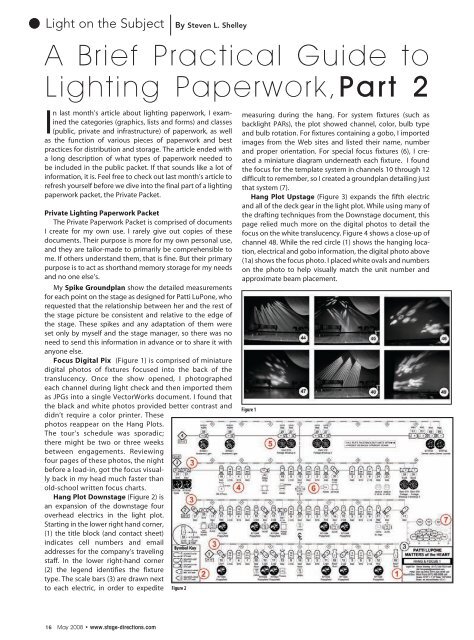
Focus Digital Pix (Figure 1) is comprised of miniature<br />
digital photos of fixtures focused into the back of the<br />
translucency. Once the show opened, I photographed<br />
each channel during light check and then imported them<br />
as JPGs into a single VectorWorks document. I found that<br />
the black and white photos provided better contrast and<br />
didn’t require a color printer. These<br />
photos reappear on the Hang Plots.<br />
The tour’s schedule was sporadic;<br />
there might be two or three weeks<br />
between engagements. Reviewing<br />
four pages of these photos, the night<br />
before a load-in, got the focus visually<br />
back in my head much faster than<br />
old-school written focus charts.<br />
Hang Plot Downstage (Figure 2) is<br />
an expansion of the downstage four<br />
overhead electrics in the light plot.<br />
Starting in the lower right hand corner,<br />
(1) the title block (and contact sheet)<br />
indicates cell numbers and email<br />
addresses for the company’s traveling<br />
staff. In the lower right-hand corner<br />
(2) the legend identifies the fixture<br />
type. The scale bars (3) are drawn next<br />
to each electric, in order to expedite Figure 2<br />
measuring during the hang. For system fixtures (such as<br />
backlight PARs), the plot showed channel, color, bulb type<br />
and bulb rotation. For fixtures containing a gobo, I imported<br />
images from the Web sites and listed their name, number<br />
and proper orientation. For special focus fixtures (6), I created<br />
a miniature diagram underneath each fixture. I found<br />
the focus for the template system in channels 10 through 12<br />
difficult to remember, so I created a groundplan detailing just<br />
that system (7).<br />
Hang Plot Upstage (Figure 3) expands the fifth electric<br />
and all of the deck gear in the light plot. While using many of<br />
the drafting techniques from the Downstage document, this<br />
page relied much more on the digital photos to detail the<br />
focus on the white translucency. Figure 4 shows a close-up of<br />
channel 48. While the red circle (1) shows the hanging location,<br />
electrical and gobo information, the digital photo above<br />
(1a) shows the focus photo. I placed white ovals and numbers<br />
on the photo to help visually match the unit number and<br />
approximate beam placement.<br />
Figure 1<br />
16 May 2008 • www.stage-directions.com