technical manual (PDF 419k) - Power Drive Systems Generator ...
technical manual (PDF 419k) - Power Drive Systems Generator ...
technical manual (PDF 419k) - Power Drive Systems Generator ...

You also want an ePaper? Increase the reach of your titles
YUMPU automatically turns print PDFs into web optimized ePapers that Google loves.
DEEP SEA ELECTRONICS<br />
556<br />
ATS / MAINS<br />
CONTROLLER<br />
FEATURES<br />
Automatically senses mains<br />
(utility) failure and starts the<br />
backup generators (controlled by<br />
DSE model 550 controllers).<br />
<br />
<br />
Allows precise changes to be<br />
made to the generator bus/mains<br />
supply load share (import/export<br />
control)<br />
Can maintain a specific mains<br />
(utility) or generator power factor.<br />
ATS / Peak lopping control for 550<br />
controlled generator bus<br />
Will synchronise multiple 550<br />
controlled gensets with the<br />
returning mains (utility) supply to<br />
provide no-break changeover<br />
back to the mains supply.<br />
<br />
<br />
<br />
<br />
<br />
<br />
‘Soft transfer’ (load ramping) both<br />
to and from the generator supply.<br />
Can be used to load test the<br />
synchronised generator bus<br />
without removing power from the<br />
load.<br />
Clear, backlit LCD display to show<br />
the status of the load switches,<br />
and mains (utility) supply as well<br />
as to annunciate alarm conditions<br />
should they occur.<br />
Integral, configurable starting and<br />
stopping timers.<br />
Configurable inputs and outputs<br />
to help meet complex<br />
specifications.<br />
Integral log for viewing event<br />
history.<br />
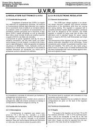
INSTRUMENTATION<br />
The 556 module provides the following<br />
instrumentation LCD displays, accessed<br />
via the LCD PAGE and DISPLAY<br />
SCROLL push buttons:<br />
• Mains Volts L1-N, L2-N, L3-N<br />
• Mains Volts L1-L2, L2-L3, L3-L1<br />
• Mains Amps L1,L2,L3<br />
• Mains Frequency Hz<br />
• Mains kVA L1,L2,L3, Total<br />
• Mains kW L1,L2,L3, Total<br />
• Mains pf L1,L2,L3,Average<br />
• Mains kVAr L1,L2,L3, Total<br />
• Mains KWh, KVAh, KVArh<br />
• Mains Phase Sequence<br />
• Synchroscope Display<br />
• Bus Volts L1-N, L2-N, L3-N<br />
• Bus Volts L1-L2, L2-L3, L3-L1<br />
• Bus Frequency Hz<br />
• Bus kW total and % of capacity<br />
• Bus kVAr total and % of capacity<br />
• Bus Phase Sequence<br />
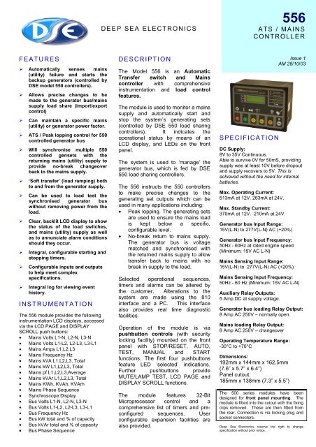
DESCRIPTION<br />
The Model 556 is an Automatic<br />
Transfer switch and Mains<br />
controller with comprehensive<br />
instrumentation and load control<br />
features.<br />
The module is used to monitor a mains<br />
supply and automatically start and<br />
stop the system’s generating sets<br />
(controlled by DSE 550 load sharing<br />
controllers). It indicates the<br />
operational status by means of an<br />
LCD display, and LEDs on the front<br />
panel.<br />
The system is used to ‘manage’ the<br />
generator bus, which is fed by DSE<br />
550 load sharing controllers.<br />
The 556 instructs the 550 controllers<br />
to make precise changes to the<br />
generating set outputs which can be<br />
used in many applications including:<br />
• Peak lopping. The generating sets<br />
are used to ensure the mains load<br />
is kept below a specific,<br />
configurable level.<br />
• No-break return to mains supply.<br />
The generator bus is voltage<br />
matched and synchronised with<br />
the returned mains supply to allow<br />
transfer back to mains with no<br />
break in supply to the load.<br />
Selected operational sequences,<br />
timers and alarms can be altered by<br />
the customer. Alterations to the<br />
system are made using the 810<br />
interface and a PC. This interface<br />
also provides real time diagnostic<br />
facilities.<br />
Operation of the module is via<br />
pushbutton controls (with security<br />
locking facility) mounted on the front<br />
panel with STOP/RESET, AUTO,<br />
TEST, MANUAL and START<br />
functions. The first four pushbuttons<br />
feature LED ‘selected’ indications.<br />
Further pushbuttons provide<br />
MUTE/LAMP TEST, LCD PAGE and<br />
DISPLAY SCROLL functions.<br />
The module features 32-Bit<br />
Microprocessor control and a<br />
comprehensive list of timers and preconfigured<br />
sequences. User<br />
configurable expansion facilities are<br />
also provided.<br />
SPECIFICATION<br />
DC Supply:<br />
8V to 35V Continuous.<br />
Able to survive 0V for 50mS, providing<br />
supply was at least 10V before dropout<br />
and supply recovers to 5V. This is<br />
achieved without the need for internal<br />
batteries.<br />
Max. Operating Current:<br />
513mA at 12V. 263mA at 24V.<br />
Max. Standby Current:<br />
370mA at 12V. 210mA at 24V.<br />
<strong>Generator</strong> bus Input Range:<br />
15V(L-N) to 277V(L-N) AC (+20%)<br />
<strong>Generator</strong> bus Input Frequency:<br />
50Hz - 60Hz at rated engine speed<br />
(Minimum: 15V AC L-N)<br />
Mains Sensing Input Range:<br />
15V(L-N) to 277V(L-N) AC (+20%)<br />
Mains Sensing Input Frequency:<br />
50Hz - 60 Hz (Minimum: 15V AC L-N)<br />
Auxiliary Relay Outputs:<br />
5 Amp DC at supply voltage.<br />
<strong>Generator</strong> bus loading Relay Output:<br />
8 Amp AC 250V – normally open.<br />
Mains loading Relay Output:<br />
8 Amp AC 250V – changeover<br />
Operating Temperature Range:<br />
-30°C to +70°C<br />
Dimensions:<br />
192mm x 144mm x 162.5mm<br />
(7.6” x 5.7” x 6.4”)<br />
Panel cutout:<br />
185mm x 138mm (7.3” x 5.5”)<br />
Issue 1<br />
AM 28/10/03<br />
The 500 series modules have been<br />
designed for front panel mounting. The<br />
module is fitted into the cutout with the fixing<br />
clips removed. These are then fitted from<br />
the rear. Connection is via locking plug and<br />
socket connectors.<br />
Deep Sea Electronics reserve the right to change<br />
specification without prior notice.
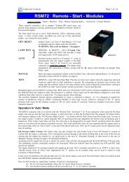
CASE DIMENSIONS<br />
192mm x 144mm x 162.5mm (7.6” x 5.7” x 6.4”)<br />
Panel cutout – 185mm x 138mm (7.3” x 5.5”)<br />
137mm<br />
144.0mm<br />
155.0mm<br />
185.0mm<br />
192.0mm<br />
7.5mm<br />
Panel Cut-out:138mmx185mm<br />
SINGLE LINE DIAGRAM OF TYPICAL MULTISET SYSTEM<br />
AVR / Governor control<br />
Multiset Communications Link<br />
From 1 to 16 sets can be connected to the MSC Link. Only three are shown for clarity<br />
Bus monitoring<br />
For typical connections to the 556<br />
controller, refer to the product<br />
operators <strong>manual</strong>.<br />
<strong>Generator</strong> breaker control<br />
Bus monitoring<br />
Mains monitoring<br />
AVR / Governor control<br />
Bus monitoring<br />
Bus and Mains<br />
Breaker control<br />
<strong>Generator</strong> breaker control<br />
AVR / Governor control<br />
Bus monitoring<br />
<strong>Generator</strong> breaker control