Series CM Users Manual PDF - Myers Power Products, Inc.
Series CM Users Manual PDF - Myers Power Products, Inc.
Series CM Users Manual PDF - Myers Power Products, Inc.

Create successful ePaper yourself
Turn your PDF publications into a flip-book with our unique Google optimized e-Paper software.
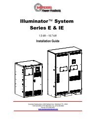
Illuminator System<br />
<strong>Series</strong> <strong>CM</strong><br />
.5 kW – 2.0 kW<br />
User’s <strong>Manual</strong><br />
Corporate Headquarters • 2000 Highland Ave, Bethlehem, PA 18020<br />
1-800-526-5088 • (610) 868-3500 • Fax: (610) 868-8686<br />
Service: (610) 868-5400<br />
www.myerspowerproducts.com
C A U T I O N<br />
READ ENTIRE MANUAL AND REVIEW ALL DOCUMENTATION BEFORE ATTEMPTING SYSTEM<br />
INSTALLATION<br />
FOR SERVICE OR INSTALLATION INFORMATION:<br />
TELEPHONE: (610) 868-5400 (24 HR. HOTLINE)<br />
FAX: (610) 954-8227<br />
FOR YOUR PROTECTION<br />
PLEASE COMPLETE AND RETURN WARRANTY REGISTRATION CARD IMMEDIATELY.<br />
1<br />
113904 – System <strong>Users</strong> <strong>Manual</strong>
This unit contains LETHAL VOLTAGES. All repairs and service should be performed by<br />
AUTHORIZED SERVICE PERSONNEL ONLY! There are NO USER SERVICEABLE<br />
PARTS inside this unit.<br />
IMPORTANT SAFEGUARDS<br />
When using electrical equipment, you should always follow basic safety<br />
precautions, including the following:<br />
1. READ AND FOLLOW ALL SAFETY<br />
INSTRUCTIONS.<br />
2. Do not install the system outdoors.<br />
3. Do not install near gas or electric heaters or in other high-temperature<br />
locations.<br />
4. Use caution when servicing batteries. Depending on battery type, batteries<br />
contain either acid or alkali and can cause burns to skin and eyes. If<br />
battery fluid is spilled on skin or in the eyes, flush with fresh water and<br />
contact a physician immediately.<br />
5. Equipment should be mounted in locations where unauthorized personnel<br />
will not readily subject it to tampering.<br />
6. The use of accessory equipment not recommended by Manufacturer may<br />
cause an unsafe condition and void the warranty.<br />
7. Do not use this equipment for other than its intended use.<br />
8. Qualified service personnel must perform all servicing of this equipment.<br />
SAVE THESE INSTRUCTIONS<br />
The installation and use of this product must comply with all national, federal,<br />
state, municipal, or local codes that apply. If you need help, please call<br />
Service.<br />
2<br />
113904 – System <strong>Users</strong> <strong>Manual</strong>
User’s Guide<br />
An on-site permanent log of the inspection, testing, and maintenance of the emergency<br />
electrical power supply system shall be maintained in accordance with the<br />
Manufacturer's operating manual. The log shall include:<br />
The date on which the inspection, testing, and maintenance exercise was carried out.<br />
The name of the person(s) who performed the inspection, testing, and maintenance.<br />
A note of any unsatisfactory condition observed or discovered, and the steps taken to<br />
correct the condition.<br />
3<br />
113904 – System <strong>Users</strong> <strong>Manual</strong>
C H A P T E R 1<br />
INTRODUCTION<br />
Keep this manual and the System Installation Guide in the folder mounted inside the<br />
unit.<br />
This unit is a microprocessor controlled PWM (Pulse Width Modulated) pure sine wave<br />
based DC to AC power inverter utilizing MOSFET technology. It integrates a fully automatic<br />
3-rate battery charger, a solid-state transfer system, control circuitry, self testing and<br />
recording digital meter display, and maintenance free sealed lead calcium type batteries.<br />
The system components are carefully matched to make the unit a completely self-contained,<br />
fully automatic standby power source for operation on all types of lighting loads. The<br />
batteries are sized and tested per UL-924 and Life Safety Code ANSI / NFPA 101, providing<br />
emergency power for a minimum of 90 minutes.<br />
If the duration of a power failure is greater than the batteries storage capability, the inverter<br />
will automatically shut down when the battery voltage reaches 85% of the nominal DC<br />
voltage. This feature protects the battery from being permanently damaged from a deep<br />
discharge that could cause cell reversal. This battery protection feature is called "Low<br />
Voltage Disconnect" or L.V.D.<br />
When the AC power is restored after a full discharge, the system will be ready for another<br />
power failure within 24hrs. If another power failure occurs before the 24-hour recharge time,<br />
the run time will be decreased.<br />
The front panel display incorporates an alphanumeric 2x20 LCD character display, LED<br />
status indicators and a 4 x 4 keypad. All user interface functions are available from the front<br />
panel assembly.<br />
Utilizing a small footprint, this unit is for use with any lighting load including quartz, HID,<br />
incandescent, fluorescent and halogen.<br />
HOW TO USE THIS MANUAL<br />
This manual tells you how to start, operate, and communicate with your unit and lets you<br />
know how to get more information for special situations.<br />
Please record your unit’s model number, serial number, and part number below. You can<br />
find these numbers on the labels on the inside panel.<br />
Model Number __________________________<br />
Serial Number __________________________<br />
Part Number ___________________________<br />
4<br />
113904 – System <strong>Users</strong> <strong>Manual</strong>
Service and Support<br />
We are committed to outstanding customer service. A service technician is<br />
available 24 hours a day, 365 days a year. Service is also available 24 hours a day to give<br />
you access to technical notes and product information. You can also visit our web site.<br />
NOTE: Please have your unit’s Serial and Model numbers available when you call; this<br />
number is located behind the left door.<br />
Contact SERVICE one of the following ways:<br />
Service Number: 610-868-5400<br />
Service Fax: 610-954-8227<br />
World Wide Web Site: www.myerscpi.com<br />
5<br />
113904 – System <strong>Users</strong> <strong>Manual</strong>
C H A P T E R 2<br />
Environment<br />
Make sure the environment is a clean, cool, dry place with normal ventilation.<br />
Storage Temperature<br />
Store the batteries (in the system or battery cabinet) at -18 to 40°C (0 to 104°F). Batteries<br />
have a longer shelf life if they are stored below 25°C (77°F). Keep stored batteries fully<br />
charged. Recharge the batteries every 90–120 days. The system or battery cabinet without<br />
batteries may be stored at -20 to 70°C (-4 to 158°F).<br />
Ventilation<br />
The air around the unit must be clean, dust-free, and free of corrosive chemicals or other<br />
contaminants. Do not place the system or batteries in a sealed room or container.<br />
Operating Temperature<br />
System can operate from 20° to 30°C (68° to 86°F) and up to 95% relative humidity. The<br />
batteries’ service life is longer if the operating temperature stays below 25°C (77°F).<br />
Batteries<br />
The temperature should be near 25°C (77°F) for optimum battery performance. Batteries are<br />
less efficient at temperatures below 18°C (65°F), and high temperatures reduce battery life.<br />
Typically, at about 35°C (95°F), battery life is half of what it would be at a normal<br />
temperature of 25°C (77°F). At about 45°C (113°F), battery life is one-fourth of normal.<br />
Make sure that heaters, sunlight, air conditioners, or outside air vents are not directed<br />
toward the batteries. These conditions can make the temperature within battery strings vary,<br />
which can cause differences in the batteries’ voltages. Eventually, these conditions affect<br />
battery performance.<br />
If the batteries are not in the system, remember that the batteries should be installed as<br />
close as possible to the unit to reduce DC wiring costs and improve battery performance.<br />
Do not allow tobacco smoking, sparks, or flames in the system location because hydrogen is<br />
concentrated under the vent cap of each cell of the battery. Hydrogen is highly explosive,<br />
and it is hard to detect because it is colorless, odorless, and lighter than air.<br />
Every type of battery can produce hydrogen gas, even sealed maintenance-free batteries.<br />
The gas is vented through the vent caps and into the air, mainly when the unit is charging<br />
the batteries. The batteries produce the most hydrogen when maximum voltage is present in<br />
fully charged batteries; the batteries do not produce hydrogen during float charging. The<br />
amount of current that the charger supplies to the batteries (not the battery ampere-hour)<br />
determines how much hydrogen is produced.<br />
High Altitude Operation<br />
The maximum operating ambient temperature drops 1°C per 300m (2°F per 1000 ft) above<br />
sea level. Maximum elevation is 3000m (10,000 ft).<br />
6<br />
113904 – System <strong>Users</strong> <strong>Manual</strong>
C H A P T E R 3<br />
Startup and Shutdown Procedure<br />
Refer to the Installation <strong>Manual</strong> to secure the unit and install AC and DC wiring.<br />
STARTUP PROCEDURE<br />
For the initial startup of the system, follow the instructions in the Startup and Warranty<br />
Validation Form. Failure to do so will void warranty.<br />
CAUTION: HAZARDOUS VOLTAGES – ONLY QUALFIED SERVICE PERSONNEL SHOULD PERFORM PROCEDURE.<br />
1. Verify that the installation switch located below the front panel is in the OFF position.<br />
Verify that AC input is disconnected.<br />
2. Turn on the DC Circuit Breaker CB1.<br />
3. Energize the Mains AC input by turning on the units input circuit breaker and/or the<br />
Distribution Panel breaker located upstream from the inverter.<br />
4. Turn the installation switch to the On position. The Front Panel display should now<br />
be illuminated and a slight hum should be heard from the inverter transformer. The<br />
unit is now charging and the output should be energized.<br />
SHUTDOWN PROCEDURE<br />
1. Interrupt the AC Mains to the machine by the Distribution Panel Breaker or the<br />
machines input circuit breaker. The Inverter should then start.<br />
2. Turn the installation switch located on the inverter chassis to the off position. The<br />
inverter should stop.<br />
3. Turn off the DC Circuit Breaker CB1.<br />
CAUTION: HAZARDOUS VOLTAGES STILL EXIST AT THE BATTERY TERMINAL BLOCK<br />
AND WITHIN THE SYSTEM. AUTHORIZED SERVICE TECHNICIANS MUST DISCHARGE<br />
DC CAPACITORS AND TURN OFF UTILITY POWER BEFORE SERVICING EQUIPMENT.<br />
CAUTION: DO NOT LEAVE THE SYSTEM SHUTDOWN FOR A PROLONGED LENGTH OF<br />
TIME. LEAD BASED BATTERIES WILL EXPERIENCE PERMANENT DAMAGE FROM<br />
LACK OF CHARGING AFTER A FEW MONTHS.<br />
7<br />
113904 – System <strong>Users</strong> <strong>Manual</strong>
C H A P T E R 4<br />
OPERATION<br />
The following is a description of the status LED's located on the front panel and the internal fan.<br />
AC Present<br />
When the AC Mains is present, the LED will illuminate. If a power failure was long in duration, or the<br />
AC mains was disconnected by some other means (Circuit breaker open) the AC Present LED would<br />
not be illuminated. When the control circuit senses that the line has dropped below an acceptable<br />
level (Black Out, Brown Out, or Transient), the inverter will energize for at least one minute. So, if the<br />
power failure was a momentary glitch, the AC present LED would be illuminated but the inverter<br />
would be running.<br />
System Ready<br />
When the system has adequate battery voltage to transfer, the System Ready LED will illuminate.<br />
This feature prevents damage from multiple deep discharges of the battery.<br />
Battery Charging<br />
When the AC Mains is connected to the line and the battery is charging under normal conditions, the<br />
Battery Charging LED will illuminate.<br />
Battery <strong>Power</strong><br />
When the inverter is producing output power (battery is being discharged), the Battery <strong>Power</strong> LED will<br />
be illuminated.<br />
Fault<br />
This is a summary Fault indication. When there is a fault condition present, the Fault LED will<br />
illuminate. To view which fault is present, use the keypad and LCD display feature.<br />
The front panel display will provide the user with a variety of information. It has a full compliment of<br />
Meter functions, Control functions and Program functions.<br />
Fan<br />
The fan operates during emergency mode and only during normal mode when the batteries are being<br />
charged. When the batteries reach float condition (trickle charge) the fan turns off.<br />
8<br />
113904 – System <strong>Users</strong> <strong>Manual</strong>
C H A P T E R 5<br />
Front Panel Display<br />
The Front panel consists of a 2 x 20 alphanumeric LCD display with LED Back lighting, 5 Status LED<br />
indicators and a 4 x 4 keypad for user interface.<br />
Figure 5.1 Front Panel Display<br />
9<br />
113904 – System <strong>Users</strong> <strong>Manual</strong>
Control Panel Keypads<br />
Key Name<br />
Table 5.1 Keypad Functions<br />
Description<br />
Meter (Blue) Pressing this key will activate Meter Functions<br />
Control (Red) Pressing this key will activate Control Functions<br />
Program (Black) Using this key, you can enter passwords or change parameter values. To<br />
enter passwords, press [PROGRAM], enter the password, and press<br />
[ENTER]. NOTE: A password must be entered to change parameters.<br />
Enter (Grey) This key records or enters a task you perform using the control panel<br />
keys.<br />
[ ◄ ] This key functions as Left scroll key<br />
[ ► ] This key functions as Right scroll key<br />
[ 0 ] This key works as a number key; it is also used to display active alarms<br />
when in CONTROL Mode.<br />
[ 1 ] through [ 9 ] These keys work as number keys.<br />
Meter Functions<br />
Meter functions are available by pressing the METER keypad to get to the Meter<br />
Menu and then pressing the desired function keypad. (See figure 5.1)<br />
Table 5.2 Meter Functions<br />
Function Description Keypad Text<br />
Voltage Input Measures the AC Input Voltage to the Inverter V IN<br />
Voltage Output Measures the AC Output Voltage from the Inverter V OUT<br />
Current Output Measures the AC Output Current from the Inverter. If<br />
I OUT<br />
optional Normally Off loads are connected, it will read the<br />
sum of Normally On and Normally Off outputs.<br />
Battery Voltage Measures Battery Voltage V BATT<br />
Battery Current Measures the Battery Current. When in charge mode, the I BATT<br />
current will be positive. When in Inverter mode, the current<br />
will be negative.<br />
VA Output Multiplication of the output voltage and output current VA OUT<br />
Inverter Watts Multiplication of the battery voltage and the battery current INV. WATTS<br />
Inverter Minutes Total minutes the system has run on inverter<br />
INV. MIN<br />
Temperature Measures the ambient temperature of the electronics<br />
TEMP<br />
enclosure.<br />
System Days Total days the system has been in service. SYS. DAYS<br />
10<br />
113904 – System <strong>Users</strong> <strong>Manual</strong>
Control Functions<br />
Control functions are available by pressing "CONTROL" to get to the Control Menu and then<br />
pressing the desired function.<br />
Table 5.3 Control Functions<br />
Function<br />
Test Log<br />
Event Log<br />
Initiate Test<br />
Alarm Log<br />
Buzzer Silence<br />
Keypad Text<br />
TEST LOG<br />
EVENT LOG<br />
TEST<br />
ALARM<br />
BUZZER<br />
• TEST LOG - View the Test Log of the last 75 monthly or Yearly Tests. View the Date,<br />
Time, Duration, Output Voltage, Output Current, Temperature and Fault Status.<br />
Use the left and right scroll key to change event number.<br />
Use the ENTER key to select desired event number.<br />
Use the left and right scroll key to view event information about the event.<br />
Use the TEST LOG key to return to the event number.<br />
• EVENT LOG - Identical to the TEST LOG except this log records the past 75 events.<br />
• TEST - Pressing the TEST key will initiate a 1-minute test. This test will be recorded in<br />
the Event log since it is not part of the scheduled monthly or yearly test.<br />
• ALARM - View the Alarm log of the last 50 alarms. View the Date, Time and Alarm.<br />
Use the left and right scroll key to change alarm number.<br />
Use the enter key to select alarm number.<br />
Use the left and right scroll key to view information about the alarm.<br />
Use the ALARM key to return to event number.<br />
• BUZZER - Pressing this key silences the audible buzzer from a fault condition or an<br />
intermittent beep when the inverter is under battery power. If a fault caused the buzzer to<br />
alarm and the alarm is silenced, the buzzer will return after 24 hours or after the fault is<br />
cleared.<br />
Program Functions<br />
User Program Functions<br />
All program functions are password protected. The password for user level is 1234. When the<br />
PROGRAM keypad is pressed, the display will prompt the user for the password. After the<br />
password is entered (1234 + ENTER key), the user can change the Date, Time, Month Test<br />
Date, Month Test Time, Yearly Test Date and Yearly Test Time, Load Reduction Fault, Low<br />
VAC Alarm, High VAC Alarm, Ambient Temp Alarm and Near Low Battery settings.<br />
Time is always in the 24 hour standard. Example 4:00 PM is 16:00.<br />
11<br />
113904 – System <strong>Users</strong> <strong>Manual</strong>
Table 5.4 Program Functions<br />
Parameter Format Factory Default<br />
Date MM/DD/YY (Month, Date, Year) Current Date<br />
Time HH/MM (Hours, Minutes) Eastern Stand Time<br />
Monthly Test Date DD (Date) 15 th of the Month<br />
Monthly Test Time HH/MM (Hours, Minutes) 5:00<br />
Yearly Test Date MM (Month) 01<br />
Yearly Test Time HH/MM (Hours, Minutes) 8:00<br />
Load Reduction AAAA(Amps) 0.0A<br />
Low VAC Alarm VVVV(Volts) 1.0V<br />
High VAC Alarm VVVV(Volts) 999.9V<br />
Ambient Temp Alarm DDD(Degrees Centigrade) 70°C<br />
Near Low Battery VVVV(Volts) 43VDC<br />
• Near Low Battery Voltage is in VVVV (Volts). The last digit entered is after the decimal<br />
place. I.E. (430 + ENTER) will register 43.0VDC.<br />
• Load Reduction Fault is in AAAA (Amps). The last digit entered is after the decimal place.<br />
I.E. (480 + ENTER) will register 48.0 Amps. If the output current under battery power is<br />
10 percent below this number, the alarm will be set.<br />
• Low AC Voltage Alarm is in VVVV (Volts). The last digit entered is after the decimal<br />
place. I.E. (1200 + ENTER) will register 120.0 Volts. If the Input AC Voltage goes below<br />
this number the alarm will be set.<br />
• High AC Voltage Alarm is similar to Low AC Voltage Alarm.<br />
• Ambient Temperature Alarm is in DDD (Degrees Centigrade). I.E. (75 + ENTER) will<br />
register 75 deg. C. When the ambient temperature internal to the inverter enclosure goes<br />
above the set point the alarm will be set.<br />
12<br />
113904 – System <strong>Users</strong> <strong>Manual</strong>
C H A P T E R 6<br />
SPECIFICATIONS<br />
Input<br />
Output<br />
Battery<br />
Environmental<br />
General<br />
General Specifications<br />
Voltage 120 or 277Vac 1-phase 2-wire +10% -15%. Contact factory for all other voltages.<br />
Input <strong>Power</strong> Walk-in Limiting inrush current to less than 125%, 10 times for 1 line cycle<br />
Input Frequency 60Hz, +/- 3%, 50Hz Available upon request<br />
Synchronizing Slew Rate 1Hz per second nominal<br />
Protection Input Circuit Breaker<br />
Harmonic Distortion < 10%<br />
<strong>Power</strong> Factor .5 lag/lead<br />
Voltage 120 or 277Vac 1-phase 2-wire. Contact factory for all other voltages.<br />
Static Voltage Load current change +/-2%, battery discharge +/-12.5%<br />
Dynamic Voltage +/- 2% for +/-25% load step change, +/-3% for a 50% load step change, recovery within 3 cycles<br />
Harmonic Distortion < 3% THD for linear load<br />
Overload Fuse protected<br />
Output Frequency 60Hz +/- .05Hz during emergency mode<br />
Load <strong>Power</strong> Factor .5 lag to .5 lead<br />
Inverter Overload 125% for 5 minutes<br />
Protection Circuit Breaker<br />
Type Valve-regulated sealed lead-calcium.<br />
Charger Microprocessor controlled for various battery types and temperature compensating (recharge per UL924 spec)<br />
Protection Automatic low-battery disconnect; automatic restart upon utility return.<br />
Disconnect Circuit Breaker & Fuse<br />
Optional Runtimes Extended runtimes available. Consult factory for additional information.<br />
Altitude < 10,000 feet (above sea level) without derating<br />
Operating Temperature 20 to 30 degree Celsius<br />
Storage Temperature -20 to 70 degrees Celsius (electronics only)<br />
Relative Humidity < 95% (non-condensing)<br />
Design Stand-By UPS System. PWM inverter type utilizing MOSFET technology with 2mS transfer time.<br />
Generator Input Compatible with generators.<br />
Control Panel Microprocessor controlled 2 x 20-charactor Display with touch pad controls & functions<br />
5 LED indicators & alarm with ring-back feature<br />
Metering Input & Output Voltage, Battery Voltage, Battery & Output Current, Output VA, Temperature, Inverter Wattage<br />
Alarms High/Low Battery Charger Fault, Near Low Battery, Low Battery, Load Reduction Fault, Output Overload,<br />
High/Low AC Input Volts, High Ambient Temperature, Inverter Fault, Output Fault, Optional Circuit Breaker Trip<br />
Communications Optional RS-232 port (DB9)<br />
<strong>Manual</strong> Maintenance Bypass Optional external without internal distribution breakers.<br />
Alarm Contacts Optional Summary Form "C" Contacts<br />
Warranty 1 year standard warranty includes all parts, labor, & travel expenses within 48 contiguous states. Up to 10 years<br />
prorated warranty on batteries. Extended warranties, preventative maintenance and customized service plans<br />
are available.<br />
Factory Start-up Purchase factory start-up & receive 1 additional year of warranty.<br />
5 Year Service Plan Purchase 5 year service plan & receive free factory start-up.<br />
Physical Cabinet Freestanding NEMA Type 1<br />
Cooling Forced Air, during emergency mode.<br />
Cable Entry Left-Side<br />
Access Front<br />
13<br />
113904 – System <strong>Users</strong> <strong>Manual</strong>
C H A P T E R 7<br />
MAINTENANCE AND SERVICE<br />
The Self-testing feature of the inverter ensures that the system is tested at least once per<br />
month for 5 minutes and once per year for 90 minutes. If there are any problems with the<br />
self-tests, the fault log shall indicate which faults occurred. Please see the fault descriptions<br />
and troubleshooting guide.<br />
A few simple maintenance operations performed periodically will help ensure many years of<br />
trouble free operation. Battery terminals should be checked for tightness and corrosion. If<br />
severe corrosion is evident, maintenance is required to correct this situation.<br />
Since the unit depends on unrestricted airflow for cooling of power handling components, it<br />
is important to keep the air vents free of any obstruction. If the environment tends to be<br />
extremely dusty, occasionally blow away any accumulation of dust on components. Please<br />
follow the shutdown procedure before cleaning.<br />
CAUTION: Follow the shutdown procedure (See Chapter 3) before cleaning. An authorized<br />
technician only should perform Service!<br />
Table 7.1 Preventive Maintenance Schedule<br />
PERFORM SERVICE EVERY:<br />
SERVICE TO PERFORM: 3 MONTHS 6 MONTHS 12 MONTHS<br />
X<br />
1. TEST UNIT:<br />
NOTE: Perform manual test only when critical load is<br />
connected but not required.<br />
----- Output voltage should be present.<br />
----- Confirm operations of front panel indicators.<br />
2. INSPECT BATTERIES:<br />
X<br />
----- All connections are tight.<br />
----- Connections have no corrosion. (Clean if<br />
necessary).<br />
CLEAN UNIT: NOTE: Unit must be shut down<br />
during this service.<br />
----- Inspect air vents and clean if necessary.<br />
----- Clean excessive dust from inside cabinet(s).<br />
----- Clean excessive dust from fan(s).<br />
X<br />
"X" Indicates when to perform service. Lines below the "X" are for the date of service.<br />
14<br />
113904 – System <strong>Users</strong> <strong>Manual</strong>
TROUBLE SHOOTING CHART<br />
THE NUMBER IN THE<br />
CHART INDICATES<br />
ORDER IN WHICH<br />
PROBLEMS SHOULD<br />
BE CHECKED<br />
PROBLEMS<br />
Installation switch on<br />
inverter in off position<br />
Shorted IGBT<br />
module(s)<br />
No AC input voltage<br />
Defective inverter<br />
Output volt-ampere<br />
rating of unit being<br />
exceeded<br />
Ambient temperature too<br />
high, vents blocked<br />
Shorted load<br />
Reverse battery<br />
diodes shorted<br />
Open battery fuse (&<br />
fuses in battery cabinet<br />
if applicable)<br />
Battery polarity wrong<br />
Defective charger<br />
Battery capacity low<br />
Low water in battery<br />
(optional w/ wet cells)<br />
Wrong amount of battery<br />
cells in series<br />
Batteries dead, low or<br />
defective<br />
Transfer module and/or<br />
control circuit<br />
malfunction<br />
Transformer not<br />
connected for proper<br />
voltage<br />
S<br />
Y<br />
M<br />
P<br />
T<br />
O<br />
M<br />
S<br />
Inverter<br />
will not<br />
run<br />
during a<br />
power<br />
failure<br />
1<br />
3<br />
4<br />
6<br />
2<br />
11<br />
7<br />
10<br />
9<br />
8<br />
5<br />
System<br />
draws<br />
excessive<br />
AC input<br />
current<br />
1<br />
2<br />
3<br />
System<br />
noisy,<br />
excessive<br />
transformer<br />
hum during<br />
normal run<br />
conditions<br />
1<br />
2<br />
3<br />
AC output<br />
voltage<br />
low<br />
during a<br />
utility<br />
power<br />
failure<br />
3<br />
2<br />
1<br />
4<br />
System<br />
overheats,<br />
smells,<br />
smokes,<br />
etc.<br />
3<br />
2<br />
1<br />
4<br />
6<br />
5<br />
System<br />
noisy,<br />
transformer<br />
hum<br />
during a<br />
power<br />
failure<br />
1<br />
2<br />
3<br />
Inverter<br />
jitters or<br />
staggers<br />
during a<br />
power<br />
failure<br />
1<br />
3<br />
2<br />
System<br />
blows<br />
battery fuse<br />
(& fuses in<br />
battery<br />
cabinet if<br />
applicable)<br />
3<br />
5<br />
6<br />
2<br />
1<br />
4<br />
Charger<br />
not<br />
charging<br />
properly,<br />
batteries<br />
low or<br />
dead<br />
2<br />
6<br />
3<br />
4<br />
5<br />
1<br />
Charger<br />
stays in<br />
HI<br />
charge<br />
1<br />
2<br />
3<br />
Batteries<br />
require<br />
continuous<br />
addition<br />
of water to<br />
keep proper<br />
level<br />
(optional w/<br />
wet cells)<br />
3<br />
1<br />
2<br />
4<br />
Battery<br />
acid<br />
leaking<br />
in<br />
cabinet<br />
or<br />
around<br />
tops of<br />
batteries<br />
1<br />
2<br />
4<br />
3<br />
Battery<br />
voltage<br />
does<br />
not read<br />
properly<br />
after<br />
Installation<br />
of<br />
fresh<br />
cells<br />
4<br />
3<br />
1<br />
2<br />
Battery<br />
Voltage<br />
low<br />
or non<br />
existent<br />
1<br />
2<br />
3<br />
4<br />
5<br />
15<br />
113904 – System <strong>Users</strong> <strong>Manual</strong>
RETURN MATERIAL AUTHORIZATION (RMA) POLICY<br />
No return material is accepted without written "Return Material Authorization"(RMA). An<br />
RMA number is obtainable by contacting the Field Service Department.<br />
Every effort will be made to correct problems over the phone before a RMA is granted or a<br />
service trip made. Cooperation will save both time and expense for customer and<br />
manufacturer.<br />
If it is deemed necessary to return material, the RMA number must appear on shipping<br />
labels, packing slips, and bills of lading.<br />
OUT OF WARRANTY REPAIR CHARGES AND LABOR<br />
Contact Field service for current parts and labor rates. A minimum rate will be assessed.<br />
The manufacturer will not proceed with repairs of an out of warranty unit until authorization<br />
in the form of a purchase order is received from the customer. The unit for repair must be<br />
returned prepaid with an RMA number on the carton. For travel to the job site, a quote "Not<br />
to Exceed" estimate will be given. A purchase order to cover that amount is required before<br />
a trip to the job site is made.<br />
16<br />
113904 – System <strong>Users</strong> <strong>Manual</strong>
LIMITED WARRANTY<br />
The parts and on-site labor for the electronics portion of this equipment are warranted<br />
against defects in workmanship and material for a period of one year from time of shipment,<br />
but in no case will this warranty be valid if installation of equipment is not accomplished<br />
within 180 days from date of shipment. Batteries cannot be disconnected from the unit for<br />
long periods (180 days) or they will not be able to charge, creating malfunction of both<br />
batteries and/or electronics and thereby voiding the warranty. Systems ordered with "Heavy<br />
Lead" batteries over 25 Ah have a one year unconditional battery warranty with an additional<br />
prorated warranty contingent upon timely return of warranty registration card and the terms<br />
called out in the particular battery warranty sheet. See individual battery warranty policy.<br />
The warranty does not cover damage caused by abuse, improper environmental conditions,<br />
shipping damage, improper electronics and/or battery installation, unauthorized<br />
modifications, service by unauthorized personnel, transportation of damaged equipment, or<br />
acts of war. Damage due to lack of maintenance (where applicable) or damage resulting<br />
from installation in areas with other than normal temperatures are not covered. See the<br />
battery warranty policy for details, as adverse environmental conditions reduce battery life<br />
and void the warranty. Replacement of fuses, pilot lamps, and/or contractor labor is not<br />
included in warranty. Damage do to acts of nature, such as, but not limited to, lightning,<br />
flooding, explosions and earthquakes, are not covered.<br />
The warranty is limited to the repair and/or replacement of parts and/or units that upon<br />
examination at our factory and/or job site are determined to be defective and in our<br />
judgment are subject to repair or replacement.<br />
All such repair shall be manufacturer's exclusive remedy. A date code, part number and<br />
serial number identify all such units.<br />
TO THE EXTENT ALLOWED BY LAW, MYERS/CPI DISCLAIMS ALL OTHER<br />
WARRANTIES, EXPRESS OR IMPLIED, INCLUDING, BUT NOT LIMITED TO, AND LEED<br />
WARRANTIES OR MERCHANT ABILITY OR FITNESS FOR A PARTICULAR PURPOSE,<br />
AND ANY IMPLIED WARRANTY OF MERCHANT ABILITY OR FITNESS FOR A<br />
PARTICULAR PURPOSE ON PRODUCT IS LIMITED IN DURATION TO THE DURATION<br />
OF THIS WARRANTY. TO THE EXTENT ALLOWED BY LAW, THE MANUFACTURER<br />
SHALL NOT BE LIABLE FOR ANY SPECIAL, INCIDENTAL, OR CONSEQUENTIAL<br />
DAMAGES INCLUDING, BUT NOT LIMITED TO, LOSS OF PROFITS, INJURIES TO<br />
PROPERTY, LOSS OF USE OF THE PRODUCT OR ANY ASSOCIATED EQUIPMENT.<br />
Special on site extended warranties are also available upon request. The warranty period<br />
may be adjusted because of special circumstances, but only by arrangement with the<br />
manufacturer at the time of purchase.<br />
All in or out of warranty repaired material or replacement units/parts carry a 90-day new part<br />
guarantee. Return of your original repaired component or unit is not guaranteed.<br />
This limited warranty is for the 48 contiguous states, Puerto Rico, and the U.S. Virgin<br />
Islands.<br />
For international warranty information, call the Field Service Department. See telephone<br />
number in front of manual. The standard warranty can be extended and renewed for a<br />
nominal fee. Please contact the factory for pricing information.<br />
17<br />
113904 – System <strong>Users</strong> <strong>Manual</strong>