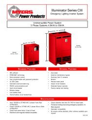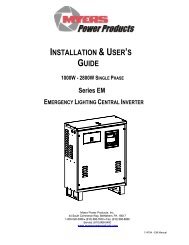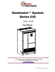
AIA Spec for Illuminator Series CIII DOC - Myers Power Products, Inc.
AIA Spec for Illuminator Series CIII DOC - Myers Power Products, Inc.
AIA Spec for Illuminator Series CIII DOC - Myers Power Products, Inc.

You also want an ePaper? Increase the reach of your titles
YUMPU automatically turns print PDFs into web optimized ePapers that Google loves.
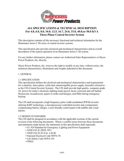
<strong>AIA</strong> SPECIFICATIONS & TECHNICAL DESCRIPTION<br />
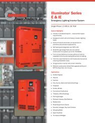
For 4.8, 6.0, 8.0, 10.0, 12.5, 16.7, 24.0, 33.0, 40.0,or 50.0 KVA<br />
Three-Phase Central Inverter System<br />
This description contains all the necessary functional and technical in<strong>for</strong>mation <strong>for</strong> the<br />
<strong>Illuminator</strong> <strong>Series</strong> C III series of central inverter systems.<br />
This specification also provides electrical and mechanical characteristics and an overall<br />
description of the typical operation of an <strong>Illuminator</strong> <strong>Series</strong> C III system.<br />
For any further in<strong>for</strong>mation, please contact our Authorized Sales Representative or <strong>Myers</strong><br />
<strong>Power</strong> <strong>Products</strong>, <strong>Inc</strong>. directly.<br />
<strong>Myers</strong> <strong>Power</strong> <strong>Products</strong>, <strong>Inc</strong>. reserves the right to modify at any time, without notice, the<br />
technical characteristics, illustrations and weights indicated in this document.<br />
1. GENERAL<br />
1.1 SPECIFICATION<br />
This specification defines the electrical and mechanical characteristics and requirements<br />
<strong>for</strong> a stand-by, three-phase, solid-state uninterruptible power supply, hereafter referred to<br />
as the CIS (Central Inverter System). The CIS shall provide high quality, computer grade<br />
AC power <strong>for</strong> today's electronic lighting loads (power factor corrected and self-ballast<br />
fluorescent, incandescent, quartz re-strike and halogen, and HID) during emergency<br />
backup.<br />
The CIS shall incorporate a high frequency pulse width modulated (PWM) inverter<br />
utilizing IGBT technology, a microprocessor controlled inverter and a temperature<br />
compensating battery charger, a user-friendly control panel with audible and visual<br />
alarms.<br />
1.2 DESIGN STANDARDS<br />
The CIS shall be designed in accordance with the applicable sections of the current<br />
revision of the following documents. Where a conflict arises between these documents<br />
and statements made herein, the statements in this specification shall supersede.<br />
• UL 924 Standard <strong>for</strong> Emergency Lighting and <strong>Power</strong> Equipment<br />
• ANSI C62.41 (IEEE 587)<br />
• ANSI C62.42.45 (Cat. A & B)<br />
• National Electrical Code NFPA-70<br />
• Life Safety Code NFPA-101<br />
• OSHA<br />
1 of 1
1.3 SYSTEM DESCRIPTION<br />
1.3.1 Design Requirements - Electronics Module<br />
A. Nominal Input/Output Voltage<br />
The input and output voltage of the CIS shall be pre-configured to match the user<br />
specified input and load requirements. Available voltages are 120/208 or 227/480<br />
VAC.<br />
Input: _____ VAC, 3-phase, 4-wire-plus-ground<br />
Output: _____ VAC, 3-phase, ____-wire-plus-ground<br />
B. Output Load Capacity<br />
The output load capacity of the CIS shall be rated in kVA at unity power factor.<br />
The CIS shall be able to supply the rated kW from .5 lagging to .5 leading.<br />
Rating: _____ kVA<br />
1.3.2 Design Requirement - Battery System<br />
A. Battery Cells<br />
The CIS shall be provided with sealed, valve regulated lead acid batteries.<br />
B. Reserve Time<br />
The battery system shall be sized to provide the necessary reserve time to feed the<br />
inverter in case of a mains failure. Battery reserve time: 90 minutes.<br />
C. Recharge Time<br />
The battery charger shall recharge the fully discharged batteries within a 24-hour<br />
period. The charger shall be an integrated 3-step with equalize, microprocessor<br />
controlled and temperature compensating.<br />
1.3.3 Modes of Operation<br />
The CIS shall be designed to operate with less than a 2-millisecond (no break) transfer<br />
time:<br />
A. Normal<br />
The CIS Inverter is normally off and the commercial AC power continuously<br />
supplies the critical load. The input converter (bi-directional trans<strong>for</strong>mer) derives<br />
power from the commercial AC power source and supplies to the inverter while<br />
simultaneously providing floating charge to the batteries.<br />
B. Emergency<br />
Upon failure of the commercial AC power the inverter instantaneously, with a<br />
maximum of a 2-millisecond break, switches its power supply from the input<br />
converter to the battery system. There shall be no loss of power to the critical<br />
load upon failure or restoration of the utility source.<br />
C. Recharge<br />
Upon restoration of commercial AC power after a power outage, the input<br />
converter shall automatically restart and start charging the batteries. The critical<br />
loads are powered by the commercial AC power again.<br />
1.3.4 Per<strong>for</strong>mance Requirements<br />
1.3.4.1 AC Input to CIS<br />
A. Voltage Configuration <strong>for</strong> Standard Units: 3-phase, 4-wire-plus-ground.<br />
2 of 2
B. Voltage Range: (+10%, -15%)<br />
C. Frequency: 60 Hz (+/- 3Hz)<br />
D. <strong>Power</strong> Factor: . 5 leading/lagging<br />
E. Inrush Current: 1.25 times nominal input current, 10 times 1 line cycle <strong>for</strong><br />
incandescent loads<br />
F. Current Limit: 125% of nominal input current<br />
G. Current Distortion: Less than 3% THD maximum from 50% to full load<br />
H. Surge Protection: Sustains input surges without damage per standards set in<br />
ANSI C62.41 (IEEE 587) & ANSI C62.42.45 (Cat. A&B)<br />
1.3.4.2 AC Output, CIS Inverter<br />
A. Voltage Configuration <strong>for</strong> Standard Units: 3-phase, 3 or 4-wire-plus-ground<br />
B. Static Voltage Stability: Load current changes +/- 2%<br />
C. Dynamic Voltage Stability: +/- 2% (25% step load), +/- 3% (50% step load)<br />
D. Dynamic Recovery Time to within 1% of nominal: 3Hz (0-100% load step)<br />
E. Output Harmonic Distortion: < 3% (with linear load)<br />
F. Frequency: 60 Hz (+/- .05Hz during emergency mode)<br />
G. Load <strong>Power</strong> Factor Range: 0.5 lagging to 0.5 leading<br />
H. Output <strong>Power</strong> Rating: kVA = kW<br />
I. Overload Capability: to 100% continuous rating<br />
to 115% <strong>for</strong> 5 minutes<br />
to 125% <strong>for</strong> 12 line cycles<br />
J. Crest Factor:
C. Descriptions of equipment to be furnished, including deviations from these<br />
specifications<br />
D. Size and weight of units to be handled by installing contractor<br />
E. Detailed layouts of customer power and control connections<br />
F. Detailed installation drawings including all terminal locations<br />
1.5.2 Central Inverter System Delivery Submittals<br />
Submittals upon CIS delivery shall include:<br />
• A complete set of submittal drawings<br />
• One set of instruction manuals. Manuals shall include a functional description<br />
of the equipment, installation, safety precautions, instructions, step-by-step<br />
operating procedures and routine maintenance guidelines, including illustrations.<br />
1.6 WARRANTY<br />
1.6.1 Central Inverter Module<br />
The inverter manufacturer shall warrant the CIS module against defects in materials and<br />
workmanship <strong>for</strong> 12 months after initial start-up or 18 months after ship date, whichever<br />
occurs first.<br />
1.6.2 Battery<br />
The battery manufacturer's standard warranty shall be passed through to the end user.<br />
Sealed Lead Calcium VRLA, 10-year life expectancy one-year full replacement warranty<br />
plus an additional nine years pro-rata.<br />
1.7 QUALITY ASSURANCE<br />
1.7.1 Manufacturer Qualifications<br />
A minimum of 35 years experience in the design, manufacture, and testing of emergency<br />
power systems is required.<br />
1.7.2 Factory Testing<br />
Be<strong>for</strong>e shipment, the manufacturer shall fully and completely test the system to assure<br />
compliance with the specification.<br />
2.0 PRODUCT<br />
2.1 FABRICATION<br />
All materials of the CIS shall be new, of current manufacture, high grade, free from all<br />
defects and shall not have been in prior service except as required during factory testing.<br />
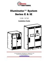
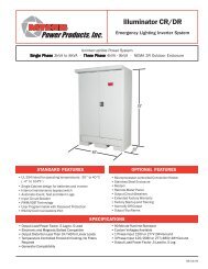
The CIS module shall be housed in a single freestanding NEMA type 1 enclosure.<br />
Battery cabinets are designed to allow stacking to minimize the overall system's footprint.<br />
Front access only shall be required <strong>for</strong> installation, adjustments and expedient servicing<br />
(MTTR: < 15 minutes). All components shall have a modular design and quick<br />
disconnect means to facilitate field service.<br />
4 of 4
The CIS shall be painted with a powder coat finish in the manufacturer's standard color.<br />
The inverter shall be constructed of replaceable subassemblies. Like assemblies and like<br />
components shall be interchangeable.<br />
Cooling of the CIS shall be <strong>for</strong>ced-air in emergency mode with internally mounted fans<br />
to minimize audible noise. Fans shall not operate in the battery charge / standby mode.<br />
Fan power shall be provided by the inverter. Maximum acoustical noise on emergency at<br />
one meter from the cabinet surface shall be no greater than 50 dBA.<br />
2.2 COMPONENTS<br />
The CIS shall be comprised of the following components:<br />
• CIS Module - The inverter module shall contain an inverter, an AC distribution panel<br />
with an input circuit breaker, control, and monitoring subsystems.<br />
• Battery Module - The battery module shall contain the battery plant required to produce<br />
the reserve energy to supply the inverter during abnormal AC mains conditions. The<br />
battery module may be contained in an external cabinet(s) depending on the system VA.<br />
2.2.1 Battery Charger<br />
A. General<br />
In the standard configuration the charger converts AC voltage to DC<br />
voltage. With commercial power present, the inverter power trans<strong>for</strong>mer is<br />
powered and the IGBT modules are microprocessor controlled to recharge<br />
the batteries. The temperature compensated battery charger circuit<br />
supplies constant voltage and constant current to the batteries. Once the<br />
batteries have received a full recharge, a constant trickle charge maintains<br />
batteries at maximum level. Recharge time is 24 hours maximum at<br />
nominal AC input voltage. The AC ripple current of the DC output meets<br />
the battery manufacturer specification, thus ensuring the maximum battery<br />
lifetime.<br />
B. AC Input Current<br />
The charger unit is provided with an AC input current limiting circuit<br />
whereby the maximum input current shall not exceed 125% of the output<br />
full current rating.<br />
C. Automatic Restart<br />
Upon restoration of utility AC power, after a utility AC power outage and<br />
after a full CIS automatic end-of-discharge shutdown, the CIS will<br />
automatically restart, per<strong>for</strong>ming the normal CIS start up.<br />
D. DC Filter<br />
The charger shall have and output filter to minimize AC ripple voltage<br />
into the battery. Under no conditions shall ripple voltage into the battery<br />
exceed 2% RMS.<br />
E. Battery Recharge<br />
The charger is capable of producing battery-charging current sufficient<br />
enough to recharge the fully discharge battery bank within a 24-hour<br />
5 of 5
period. After the battery is recharged, the charger shall maintain full<br />
battery charge until the next emergency operation.<br />
F. Over-voltage Protection<br />
The charger is equipped with a DC over-voltage protection circuit so that<br />
if the DC voltage rises above the pre-set limit, the charger is to shut down<br />
automatically and initiate an alarm condition.<br />
2.2.2 Inverter<br />
A. General<br />
The inverter converts DC voltage supplied by the battery to AC voltage of<br />
a precisely stabilized amplitude and frequency that is suitable <strong>for</strong><br />
powering most sophisticated electrical equipment. The inverter output<br />
voltage is generated by sinusoidal pulse width modulation (PWM). The<br />
use of a high carrier frequency <strong>for</strong> PWM and a dedicated AC filter circuit<br />
consisting of a trans<strong>for</strong>mer and capacitors, ensure a very low distortion of<br />
the output voltage (THD
• System output VA<br />
• Inverter wattage<br />
• System temperature<br />
• Date & time<br />
C. LED Indication<br />
The front panel with integrated LEDs, allows a quick check of the CIS<br />
operating status.<br />
• AC Present (Green)<br />
• System Ready (Green)<br />
• Battery Charging (Yellow)<br />
• Battery <strong>Power</strong> (Yellow)<br />
• Fault (Red)<br />
D. Audible Alarm<br />
Audible alarm will activate with any of the following conditions and<br />
automatically store the 50 most recent events.<br />
• High battery charger voltage<br />
• Low battery charger voltage<br />
• High AC input voltage<br />
• Low AC input voltage<br />
• Near low battery voltage<br />
• Low battery voltage<br />
• Load reduction fault<br />
• High Ambient temperature<br />
• Inverter fault<br />
• Output fault<br />
• Output overload<br />
2.2.4 RS-232 Interface<br />
The system shall be equipped with an RS-232 serial port (DB9) <strong>for</strong> remote<br />
communications.<br />
2.2.5 Manual and Programmable Testing<br />
The system shall incorporate a manual test function and two automatic test modes. The<br />
system will per<strong>for</strong>m a programmable, self-diagnostic monthly test <strong>for</strong> 5 minutes. The<br />
monthly test is preset <strong>for</strong> the 15th of every month and the user can program the event<br />
time of day. The yearly self-diagnostic test is <strong>for</strong> 90 minutes and the user can program<br />
the time of the day the event is to take place. The microprocessor automatically records<br />
the last 75 test events in its own separate test result log.<br />
2.2.6 Battery Assembly<br />
The batteries are sealed, lead-acid valve regulated battery cells with a ten year prorated<br />
warranty.<br />
Precut cable wires are included to provide easy installation. A means of disconnect shall<br />
be included <strong>for</strong> isolation of battery assembly from the CIS module.<br />
7 of 7
2.2.7 OPTIONS<br />
The central inverter system shall include the following options:<br />
____ Fast Charge<br />
____ Summary Form C Contacts<br />
2.2.8 ORDERING NUMBER<br />
The system shall be <strong>Myers</strong> CPI model:<br />
____ - D - _____ - _____ - _____ - _______ - __________ - __________ - _______ or<br />
pre-approved equal.<br />
3.0 EXECUTION<br />
3.1 WIRING<br />
All wiring shall be installed in conduit. Input and output wiring shall enter the cabinet in<br />
separate conduits.<br />
3.2 UNIT START-UP and SITE TESTING<br />
Site start-up and testing shall be provided by the manufacturer's field service<br />
representative during normal working hours (Mon. - Friday, 8 a.m. - 5 p.m.). Individual<br />
scheduling requirements can usually be met with 7 working days advance notice. Site<br />
testing shall consist of a complete test of the CIS and accessories by the inverter<br />
manufacturer in accordance with manufacturer’s standards. Manufacturer's approved<br />
service representative must per<strong>for</strong>m commissioning <strong>for</strong> two-year warranty to apply.<br />
3.3 REPLACEMENT PARTS<br />
Parts shall be available through Field Service Centers throughout the country and directly<br />
from the factory. Recommended spare parts shall be fully stocked by local field service<br />
personnel with back up available from manufacturing location.<br />
3.4 MAINTENANCE CONTRACTS<br />
A complete offering of preventive and full-service maintenance contracts <strong>for</strong> both the<br />
inverter system and batteries shall be available. An extended warranty and preventive<br />
maintenance package shall be available. Factory-trained service personnel shall per<strong>for</strong>m<br />
warranty and preventive maintenance service. A five-year maintenance contract option<br />
will include a unit start-up and site testing.<br />
8 of 8