INSTALLATION INSTRUCTIONS
INSTALLATION INSTRUCTIONS
INSTALLATION INSTRUCTIONS

Create successful ePaper yourself
Turn your PDF publications into a flip-book with our unique Google optimized e-Paper software.
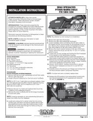
<strong>INSTALLATION</strong> <strong>INSTRUCTIONS</strong><br />
DRAG SPECIALTIES<br />
EXTENDED FORWARD CONTROL KIT FOR BIG TWINS<br />
P/N DS-243523<br />
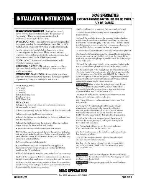
ATTENTION INSTALLER: (if other than owner):<br />
Please forward this instruction sheet to the purchaser of<br />
this product. These instructions contain valuable<br />
information necessary to the end user.<br />
INTRODUCTION: These instructions describe the procedure<br />
for properly installing the extended forward control kit on 58-86<br />
FLH, FX four-speed and 86-99 five-speed Softail models.<br />
Review instructions carefully before beginning, as they<br />
contain important information. Please retain for future<br />
reference. Particularly important information is distinguished<br />
in these instructions by the following notations:<br />
NOTE: A NOTE provides key information to make<br />
procedures easier or clearer.<br />
CAUTION: A CAUTION indicates special procedures<br />
that must be followed to avoid damage to the motorcycle<br />
and/or accessories.<br />
WARNING: A WARNING indicates special procedures<br />
that must be followed to avoid injury to a motorcycle operator<br />
or person inspecting or repairing the motorcycle.<br />
TOOLS REQUIRED<br />
7<br />
/ 16 " wrench<br />
1<br />
/ 2 " wrench<br />
9<br />
/ 16 " wrench<br />
External snap ring pliers<br />
Needlenose pliers<br />
DOT 5 brake fluid<br />
PROCEDURE:<br />
1. Support the motorcycle so that it is in a vertical position and<br />
the side stand is not used.<br />
2. Remove the existing brake and shifter controls from the motorcycle.<br />
3. Remove the side stand from the motorcycle.<br />
4. Install the shift arm into the shift bracket. Lubricate and make sure<br />
that it rotates freely.<br />
5. Install the shift bracket onto the motorcycle. Place the regulator<br />
mount between the frame and the shift bracket.<br />
6. Install the side stand on the outside of the shift bracket.<br />
NOTE: Make sure that you install the bolts through the shift bracket<br />
that are hidden under the side stand. Failure to install these bolts will<br />
cause side stand failure. We recommend that you use a thread locking<br />
adhesive on all nuts and bolts.<br />
7. Tighten all mounting bolts securely.<br />
8. Assemble the correct shift linkage rod for your application.<br />
See schematic for the correct linkage rod. The five-speed Softail<br />
models use the FX type linkage.<br />
9. Install the linkage rod using the correct rod ends and retaining rings.<br />
10. Install the foot peg and shift lever on the shifter bracket. Position<br />
the shift lever to allow ample room to place your foot onto the footpeg.<br />
11. Rotate the shift lever, making sure that it allows the transmission<br />
to shift entirely into both higher and lower gears. Reposition the shift<br />
lever or adjust the linkage rod as necessary.<br />
DRAG SPECIALTIES<br />
12. Check all fasteners to make sure they are securely tightened.<br />
13. Install the rear brake mounting bracket on the right side of<br />
the motorcycle.<br />
14. Install the rear brake lever on the mounting bracket, checking<br />
to make sure that the lever rotates freely on the bracket. Make sure<br />
to install the brake return spring at the same time. The brake lever is<br />
installed correctly when it is under the foot peg mount, allowing the<br />
spring to hold the lever up against the foot peg mount.<br />
15. Install the foot peg and the brake lever peg on the mounting bracket.<br />
16. Assemble the brake plunger and the plunger Heim joint together,<br />
making sure to use the included lock nut. Screw the plunger Heim<br />
joint as far into the brake plunger as possible. Install the brake plunger<br />
on the brake lever.<br />
17. Install the brake master cylinder to the mounting bracket. Make<br />
sure to place the brake plunger into the end of the master cylinder.<br />
18. Adjust the length of the brake plunger into the master cylinder.<br />
The brake plunger is adjusted correctly when there is approximately<br />
1<br />
/2" of free movement of the brake lever BEFORE the brake plunger<br />
contacts the piston in the master cylinder. The piston in the master<br />
cylinder must be allowed to return completely to the rear and seat<br />
against the retaining ring for correct operation.<br />
WARNING: Failure to adjust the brake plunger correctly may<br />
cause the rear brake to drag, overheat, or cause brake failure.<br />
We suggest that you have an experienced mechanic check this<br />
adjustment before you operate the motorcycle.<br />
19. Install the brake line kit. In certain circumstances you may<br />
be required to fabricate a custom brake line.<br />
20. Check all fasteners and connections to make sure that<br />
they are tight.<br />
21. Using DOT 5 brake fluid only, fill the master cylinder<br />
reservoir and bleed the rear brake system. Keep bleeding<br />
until you obtain a flow of brake fluid clear of any air bubbles<br />
from the bleeder screw on the caliper. Maintain the correct<br />
fluid level in the master cylinder during the bleeding operation.<br />
22. Allow the brake to sit for approximately 5 minutes and<br />
then test the brake system again, making sure that the brake<br />
lever is firm with no softness.<br />
23. Again check all fasteners for the correct tightness.<br />
Check the brake fluid for the correct level.<br />
24. Apply steady pressure to the brake lever and check all brake<br />
line fittings for any leaks.<br />
25. Check for adequate clearance between forward controls<br />
and front fender with forks bottomed.<br />
26. Test ride the motorcycle and check for correct shifter<br />
and brake operation. Check brake operation at low speed<br />
in a low traffic area.<br />
WARNING: Check the rear caliper and disc for overheating.<br />
Make sure that the rear wheel rotates freely. Any dragging will cause<br />
the brake to overheat and fail.<br />
WARNING: Before operating motorcycle, be sure all hardware<br />
is tight.<br />
Box 9336, Minneapolis, MN 55440<br />
Updated 4/02 Page 1 of 2
<strong>INSTALLATION</strong> <strong>INSTRUCTIONS</strong><br />
DRAG SPECIALTIES<br />
EXTENDED FORWARD CONTROL KIT FOR BIG TWINS<br />
P/N DS-243523<br />
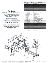
OPTIONAL MASTER CYLINDER FOR<br />
DRUM BRAKE APPKICATION<br />
79 THRU 86 TRANSMISSIONS FX MODELS<br />
79 THRU 86 TRANSMISSIONS<br />
FL AND FXWG MODELS<br />
DRAG SPECIALTIES<br />
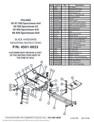
NO. QTY. DESCRIPTION<br />
1 1 Plate, brake lever<br />
2 1 Brake lever<br />
3 1 Plunger Heim joint<br />
4 1 Master cylinder<br />
5 1 Brake return spring<br />
6 1 Master cylinder plunger<br />
7 2 Foot peg<br />
8 2 Foot peg mounting kit<br />
9 1 Brake line kit<br />
10 1 Shifter bracket<br />
11 1 Shift arm<br />
12 1 Shift lever<br />
13 1 Shifter rod, FX type<br />
14 1 Shifter rod Heim joint, FX type<br />
15 1 Shifter rod Heim joint, FL type<br />
16 1 Shifter rod, FL type<br />
17 2 Peg, shifter and brake<br />
18 1 3/ 4" nylock nut<br />
19 1 3/ 8" - 16 x 4" bolt<br />
20 4 3/ 8" - 16 x 1" bolt<br />
21 2 5/ 16" - 24 x 2 1 / 4" bolt<br />
22 4 5/ 16" - 24 x 1 1 / 4" bolt<br />
23 1 1/ 4" - 28 x 5 / 16" set screw<br />
24 9 5/ 16" - 24 acorn nut<br />
25 3 3/ 8" int. tooth lockwasher<br />
26 1 5/ 16" - 24 x 1" bolt<br />
27 2 3/ 8" lockwasher<br />
28 8 5/ 16" lockwasher<br />
29 1 3/ 8" flatwasher (1 3 / 8" o.d.)<br />
30 1 Retaining ring<br />
31 3 Cable tie, black 7"<br />
32 1 1/ 4" - 28 UNF nut<br />
33 1 1/ 4" - 20 x 1" bolt<br />
34 1 1/ 4" flatwasher<br />
35 4 5/ 16" flatwasher<br />
36 1 Clevis pin kit<br />
Box 9336, Minneapolis, MN 55440<br />
Updated 4/02 Page 2 of 2