INSTALLATION INSTRUCTIONS
INSTALLATION INSTRUCTIONS
INSTALLATION INSTRUCTIONS

You also want an ePaper? Increase the reach of your titles
YUMPU automatically turns print PDFs into web optimized ePapers that Google loves.
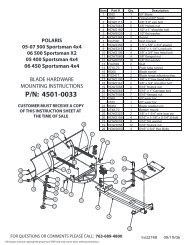
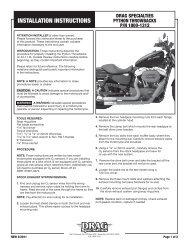
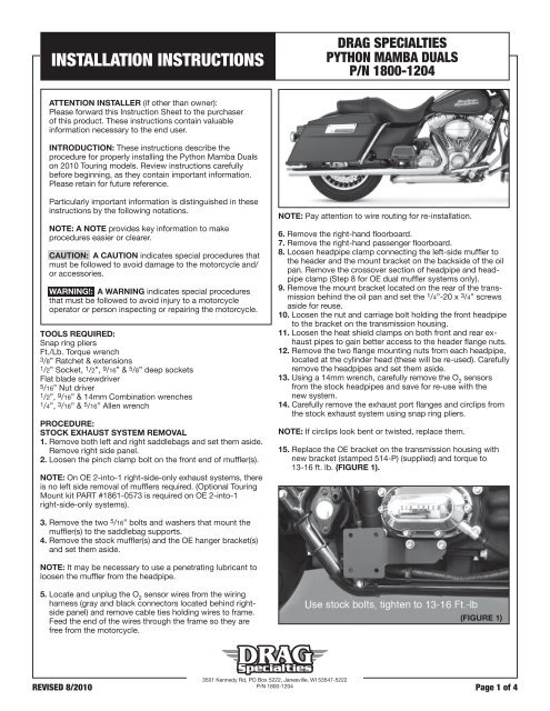
<strong>INSTALLATION</strong> <strong>INSTRUCTIONS</strong>DRAG SPECIALTIESPYTHON MAMBA DUALSP/N 1800-1204ATTENTION INSTALLER (if other than owner):Please forward this Instruction Sheet to the purchaserof this product. These instructions contain valuableinformation necessary to the end user.INTRODUCTION: These instructions describe theprocedure for properly installing the Python Mamba Dualson 2010 Touring models. Review instructions carefullybefore beginning, as they contain important information.Please retain for future reference.Particularly important information is distinguished in theseinstructions by the following notations.NOTE: A NOTE provides key information to makeprocedures easier or clearer.CAUTION: A CAUTION indicates special procedures thatmust be followed to avoid damage to the motorcycle and/or accessories.WARNING!: A WARNING indicates special proceduresthat must be followed to avoid injury to a motorcycleoperator or person inspecting or repairing the motorcycle.TOOLS REQUIRED:Snap ring pliersFt./Lb. Torque wrench3/8” Ratchet & extensions1/2” Socket, 1 /2”, 9 /16” & 5 /8” deep socketsFlat blade screwdriver5/16” Nut driver1/2”, 9 /16” & 14mm Combination wrenches1/4”, 3 /16” & 5 /16” Allen wrenchPROCEDURE:STOCK EXHAUST SYSTEM REMOVAL1. Remove both left and right saddlebags and set them aside.Remove right side panel.2. Loosen the pinch clamp bolt on the front end of muffler(s).NOTE: On OE 2-into-1 right-side-only exhaust systems, thereis no left side removal of mufflers required. (Optional TouringMount kit PART #1861-0573 is required on OE 2-into-1right-side-only systems).NOTE: Pay attention to wire routing for re-installation.6. Remove the right-hand floorboard.7. Remove the right-hand passenger floorboard.8. Loosen headpipe clamp connecting the left-side muffler tothe header and the mount bracket on the backside of the oilpan. Remove the crossover section of headpipe and headpipeclamp (Step 8 for OE dual muffler systems only).9. Remove the mount bracket located on the rear of the transmissionbehind the oil pan and set the 1 /4”-20 x 3 /4” screwsaside for reuse.10. Loosen the nut and carriage bolt holding the front headpipeto the bracket on the transmission housing.11. Loosen the heat shield clamps on both front and rear exhaustpipes to gain better access to the header flange nuts.12. Remove the two flange mounting nuts from each headpipe,located at the cylinder head (these will be re-used). Carefullyremove the headpipes and set them aside.13. Using a 14mm wrench, carefully remove the O 2sensorsfrom the stock headpipes and save for re-use with thenew system.14. Carefully remove the exhaust port flanges and circlips fromthe stock exhaust system using snap ring pliers.NOTE: If circlips look bent or twisted, replace them.15. Replace the OE bracket on the transmission housing withnew bracket (stamped 514-P) (supplied) and torque to13-16 ft. lb. (Figure 1).3. Remove the two 5 /16” bolts and washers that mount themuffler(s) to the saddlebag supports.4. Remove the stock muffler(s) and the OE hanger bracket(s)and set them aside.NOTE: It may be necessary to use a penetrating lubricant toloosen the muffler from the headpipe.5. Locate and unplug the O 2sensor wires from the wiringharness (gray and black connectors located behind rightsidepanel) and remove cable ties holding wires to frame.Feed the end of the wires through the frame so they arefree from the motorcycle.(FIGURE 1)3501 Kennedy Rd, PO Box 5222, Janesville, WI 53547-5222REVISED 8/2010P/N 1800-1204Page 1 of 4
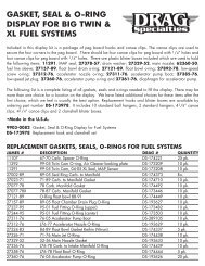
<strong>INSTALLATION</strong> <strong>INSTRUCTIONS</strong>16. Carefully remove the stock exhaust gaskets and replacethem with the supplied exhaust gaskets.PYTHON EXHAUST SYSTEM <strong>INSTALLATION</strong>1. Install mounting brackets 523-P right-side and 524-P leftside(supplied) into rubber grommets in the saddlebag supportframe by sliding tabs in from the front.NOTE: Lubrication may be required to make installation easier(Figure 2).(FIGURE 2)DRAG SPECIALTIESPYTHON MAMBA DUALSP/N 1800-12045. Assemble the front header pieces (D592FC, D593FC) using aTORCA band clamp (nut facing down) (supplied).NOTE: Tighten clamp just enough to hold theassembly together.6. Lay the front cylinder headpipe assembly (D592FC, D593FC)into its heat shield (D562HC) and loosely install the hoseclamps (supplied) into mounting clips (Figure 3). Thesmaller #20 hose clamps are used on the head pipe, thelarger #28 are used on the muffler body.NOTE: Screw heads should be accessible when the system isinstalled on motorcycle for adjustment purposes (Figure 4).Do not tighten at this time.(FIGURE 4)2. Install the crossover bracket (564-P) on the rear of transmissionusing stock hardware in the same location as the stockbracket removed earlier (Figure 8).NOTE: Do not fully tighten at this time.3. Remove headpipes and heat shields from protective packaging.Place each heat shield on a non-abrasive surface suchas a blanket or carpet. Using a felt tip pen, mark outsideedge of each heat shield to show location of mounting clipsthat hose clamps will loop through (Figure 3).7. Lay the rear cylinder headpipe (D594FC) into its heat shield(P235HC), and install the hose clamps as in step #6.8. First install flanges and then install the circlips from the stocksystem onto both new headpipes. Using stock flange nuts,carefully install headpipes onto motorcycle. Do not tighten atthis time.9. Install the nut plates and 5 /16” x 5 /8” flange bolts (supplied)to attach the pipes to the bracket 514-P (Figure 5) and theright mounting bracket 523-P. Do not tighten at this time.(FIGURE 3)4. Apply a small amount of anti-seize compound to the threadsof the O 2sensors and install them into the new headpipes,(gray connector into front headpipe and black connector intorear headpipe).NOTE: Be careful not to get anti-seize on sensor tip, it mayaffect sensor function.(FIGURE 5)10. Align pipes on motorcycle so the gap between the two heatshields is parallel where they run together (Figure 6).Tighten the exhaust port flange nuts and the 5 /16” x 5 /8”flange head bracket bolts and finally the Torca band clamp.3501 Kennedy Rd, PO Box 5222, Janesville, WI 53547-5222REVISED 8/2010P/N 1800-1204Page 2 of 4
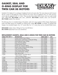
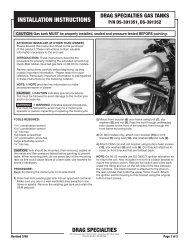
<strong>INSTALLATION</strong> <strong>INSTRUCTIONS</strong>DRAG SPECIALTIESPYTHON MAMBA DUALSP/N 1800-120411. Assemble the left muffler. First slide the header clampA223CC (supplied) over the end of the crossover headpipe(D558FC). Next assemble crossover and stub (D558FC,D556RC) together using a TORCA band clamp (nut facingdown) (supplied).NOTE: Tighten the band clamp just enough to holdassembly together.(FIGURE 6)12. Lay the left muffler assembly (D558FC, D556RC) into its heatshield (P236HC), and install the hose clamps as in step #6.13. Install TORCA Band Clamp (supplied), with the nut facingdown, on the short side expanded end of the front cylinderheadpipe (D561FC) (Figure 8).(FIGURE 8)14. Install the left muffler assembly – slip the end of D558FCinto the expanded end of the front header assembly andusing the 5 /16” x 5 /8” bolts and nut plate (supplied) securethe left muffler assembly (D558FC, D556RC) to the leftbracket 524-P.15. Referring to Figure 7, fasten the crossover pipe to thecrossover bracket using supplied hardware. First place thecrossover bracket between the arms of the header clamp.Next insert the 3 /8”-16 x 1.5 flange head bolt with a 3 /8” thinflat washer through the header clamp, crossover bracket,one heavy 1 x 3 /16” washer and once again the arm of theheader clamp. Lastly install a 3 /8” thin flat washer and 3 /8”-16 lock nut.(FIGURE 7)NOTE: Do not tighten at this time.16. Align the left header assembly so it is level with the rightside and tighten (in this sequence) the TORCA band clampat the left-side muffler body, then the 3 /8”-16 nut and boltholding the 564-P bracket and A223CC header clamptogether firmly.NOTE: Slight movement between the crossover pipe and theA223CC clamp after tightening is normal. Next tighten thescrews holding the #564-P bracket to rear of transmission tofactory specs (do not over-tighten!). Finally, tighten the TORCAband clamp holding the front header assembly (D592FC &D593FC) together.17. Install end caps (if removal was required for heat shieldinstallation) and secure with the 1 /4” x 20 screws removed.18. Check alignment of the heat shields and fully tighten allhose clamps; make adjustments as required.19. Route O 2sensor wires away from hot areas of the motorcycle.Use the nylon cable ties (supplied) to secure the O 2sensor wires to the frame. Plug the O 2sensor wires backinto the wiring harness, gray into gray, black into black.Re-install the right-side panel.20. Install Spacer (593-P), on floorboard support plate(Figure 9). Remove the left 3 /8” socket cap screw only andplace the spacer onto floorboard support platealigning the holes in the spacer with those on the supportplate. Re-install the 3 /8” socket cap screw into the originalhole-capturing spacer.NOTE: You may use the 3 /8”stock socket cap screw totemporarily hold spacer alignmentwhile tightening the 3 /8”socket cap screw.21. Install a 3 /8” lock washer(supplied) on the 3 (FIGURE 9)/8”-16 x3” socket cap screw (supplied). Using this bolt, re-install thefloorboard with ONE 1” spacing washer (supplied)(Figure 9) on the forward (right) mount.NOTE: Spacing washer is located between the floorboard supportand floorboard mount plate. On CVO Models, a 3 /8”-16 x 1- 1 /2”socket cap screw (not supplied) should be used from the inside onthe right-mount rather than the 3 /8”-16 x 3” provided bolt.3501 Kennedy Rd, PO Box 5222, Janesville, WI 53547-5222REVISED 8/2010P/N 1800-1204Page 3 of 4
<strong>INSTALLATION</strong> <strong>INSTRUCTIONS</strong>22. Re-install the right-side passenger floorboard and bothsaddle bags.23. Be sure to tighten all hardware before startingyour motorcycle.24. After installation and before starting the motorcycle, completelyclean pipes and mufflers with cleaning solvent and aclean soft cloth that will not leave residue.NOTE: Any residue, oil or fingerprints will stain the chromewhen the metal heats up.HELPFUL HINTS ABOUT EXHAUST CARE:1. When installing a new set of chrome pipes, make sure yourhands are clean and free of oil. After installation, thoroughlyclean pipes with a soft cloth and cleaning solvent that willleave no residue (chrome wax/polish, glass cleaner, alcohol,ammonia, etc.) before starting the motorcycle.2. Avoid long periods of idling as this can cause discoloration.DRAG SPECIALTIESPYTHON MAMBA DUALSP/N 1800-12043. Intake leaks can cause the engine to run lean and overheat;this could lead to discoloration.4. Make sure there are no exhaust leaks at the junction of theexhaust pipes and cylinder head. We recommend replacinggaskets if they are worn.PLEASE NOTE: Every effort is made for Python Exhaust Systemsto provide improved cornering clearance. However, dueto design and space limitations on some motorcycle models,ground and cornering clearance may not be improved and insome cases may be reduced. Be sure to follow proper installationinstructions.WARNING!: Before operating motorcycle, be sure all hardwareis tight.3501 Kennedy Rd, PO Box 5222, Janesville, WI 53547-5222REVISED 8/2010P/N 1800-1204Page 4 of 4