TELECOMMUNICATIONS TEST EQUIPMENT - Promax
TELECOMMUNICATIONS TEST EQUIPMENT - Promax
TELECOMMUNICATIONS TEST EQUIPMENT - Promax

Create successful ePaper yourself
Turn your PDF publications into a flip-book with our unique Google optimized e-Paper software.
THE DETAILS SET THE DIFFERENCE<br />
ST-240 Satellite receiver & LNB tester<br />
The ST-240 is a compact, easy to use and low cost signal generator that allows an efficient verification of<br />
satellite receivers and LNB's in two different operating modes. Both modes require the ST-240 to be connected<br />
to the satellite receiver which will be tuned to a determined frequency.<br />
In the first operating mode the tuned frequency will always be the same and will allow the satellite receiver<br />
test through the visualisation of some black and white bars on the television set that must be<br />
previously connected to the satellite receiver. In the second operating mode the ST-240 radiates signals<br />
directly in the satellite band. The satellite receiver will be tuned to a different frequency depending on the<br />
type of LNB used and will show a set of black and white bars different to the previous ones that will be<br />
displayed only when the LNB aperture is faced to the ST-240 front panel.<br />
In addition to the black and white bar patterns the ST-240 generates a 7.02 MHz audio carrier.<br />
Moreover it indicates whether the LNB supply voltage is correct or not and detects the 22 kHz switching<br />
signal.<br />
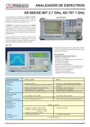
TI-330 Inserter<br />
This accessory permits to check and to test the new DiSEqC switches<br />
and LNB’s. A protocol each time more required in modern installations.<br />
The TI-330 is microprocessor controlled, making it very reliable and<br />
accurate.<br />
SPECIFICATIONS<br />
Input frequency<br />
Input level<br />
Insertion loss<br />
Input connector (from receiver meter)<br />
Type<br />
Impedance<br />
Output connector (to the accessories)<br />
Type<br />
Impedance<br />
Control signal output amplitude<br />
DC output voltage<br />
Current<br />
Overload protection<br />
Power supply<br />
From the meter<br />
Externally<br />
Mechanical features<br />
Dimensions<br />
Weigth<br />
Included accessories<br />
TI-330<br />
950-2150 MHz<br />
20 - 100 dbmV<br />
2 dB<br />
F female<br />
75 W<br />
F female<br />
75 W<br />
0.4 V (Min)<br />
0.6 V (Norm)<br />
0.8 V (Máx)<br />
Same of supply<br />
450 mA max<br />
Thermal fuse<br />
Through the coaxia cable from the<br />
level meter, 12-24 V.<br />
DC power supply<br />
W. 55 x H. 145 x D. 20 mm<br />
0.1 kg<br />
BNC-F male cable<br />
SPECIFICATIONS<br />
Input frequency<br />
Insertion loss<br />
Input / output connectors<br />
Type<br />
Impedance<br />
Output connector (to the accessories)<br />
Type<br />
Impedance<br />
Power supply<br />
Mechanical features<br />
Dimensions<br />
Weight<br />
TI-340<br />
950-2150 MHz<br />
Typ. 1.5 dB, Max. 3 dB<br />
F female<br />
75 W<br />
F female<br />
75 W<br />
Through the coaxial cable from the<br />
level meter.<br />
W. 48 x H. 98 x D. 12 mm<br />
0.1 kg<br />
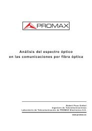
TI-340 DiSEqC checker<br />
The TI-340 permits to check at any<br />
point of an installation the presence and<br />
the state of DiSEqC signals. A set of<br />
LEDS signals indicates the presence in<br />
the coax-cable of the following signals:<br />
-Hi/Lo - Mini DiSEqC tone<br />
-H/V - 22 kHz<br />
-Position - 60 Hz<br />
-Switches- 13 and /or 18 V<br />
TI-220 22 kHz Inserter<br />
This small accessory, placed at the RF<br />
input of meters, permits insertion of a<br />
22 kHz signal, required by some<br />
LNBs to select the operation mode<br />
(band, polarisation, etc.)<br />
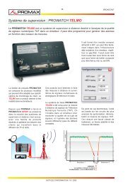
AMC/1 Master aerial<br />
The AMC/1 master aerial is a dipole with<br />
interchangeable arms (in function to the<br />
band), mounted on a hand-held mast,<br />
which, connected to field strength meter,<br />
permits the value of the electric field intensity<br />
at a particular location to be found.<br />
In order to do this, it is necessary to configure<br />
the aerial in function of the frequency,<br />
connect it to the field strength meter, and add the corresponding correction<br />
factor to the read value.<br />
25