MS Series Owner's Manual - Magnum Energy
MS Series Owner's Manual - Magnum Energy
MS Series Owner's Manual - Magnum Energy

Create successful ePaper yourself
Turn your PDF publications into a flip-book with our unique Google optimized e-Paper software.
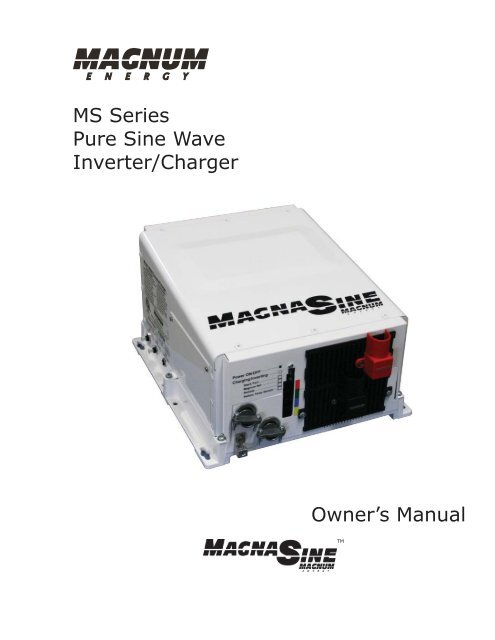
<strong>MS</strong> <strong>Series</strong><br />
Pure Sine Wave<br />
Inverter/Charger<br />
Owner’s <strong>Manual</strong><br />
TM
Disclaimer of Liability<br />
Since the use of this manual and the conditions or methods of installation, operation, use and<br />
maintenance of the <strong>MS</strong> <strong>Series</strong> Inverter/Charger is beyond the control of <strong>Magnum</strong> <strong>Energy</strong> Inc.,<br />
this company does not assume responsibility and expressly disclaims liability for loss, damage or<br />
expense, whether direct, indirect, consequential or incidental, arising out of or anyway connected<br />
with such installation, operation, use, or maintenance.<br />
Due to continuous improvements and product updates, the images shown in this manual may not<br />
exactly match the unit purchased.<br />
Restrictions on Use<br />
The <strong>MS</strong> <strong>Series</strong> Inverter/Charger shall not be used in connection with life support systems, life<br />
saving or other medical equipment or devices. Using the <strong>MS</strong> <strong>Series</strong> Inverter/Charger with this<br />
particular equipment is at your own risk.<br />
Copyright Notice<br />
Copyright © 2004, 2009 by <strong>Magnum</strong> <strong>Energy</strong>, Inc. All rights reserved. Permission to copy, distribute<br />
and/or modify this document is prohibited without express written permission by <strong>Magnum</strong><br />
<strong>Energy</strong>, Inc.<br />
Contact Information<br />
<strong>Magnum</strong> <strong>Energy</strong>, Inc.<br />
2211 West Casino Rd.<br />
Everett, WA 98204<br />
Phone: 425-353-8833<br />
Fax: 425-353-8390<br />
Web: www.magnumenergy.com<br />
Record the unit’s model and serial number in case you need to provide this information<br />
in the future. It is much easier to record this information now, instead<br />
of trying to gather it after the unit has been installed.<br />
Model:<br />
Serial Number:<br />
<strong>MS</strong>2000 (-15B/-20B)<br />
<strong>MS</strong>2012 (-15B/-20B)<br />
<strong>MS</strong>2812<br />
<strong>MS</strong>4024<br />
T1<br />
J1<br />
H1<br />
K1<br />
<strong>Magnum</strong> <strong>Energy</strong>® is a registered trademark of <strong>Magnum</strong> <strong>Energy</strong>, Inc.<br />
Page i<br />
© 2009 <strong>Magnum</strong> <strong>Energy</strong> Inc.
IMPORTANT SAFETY INSTRUCTIONS<br />
• This manual contains important safety instructions that must be followed during the installation<br />
and operation of this product.<br />
• All electrical work must be performed in accordance with local, state and federal electrical codes.<br />
• Read all instructions and safety information contained in this manual before installing or using<br />
this product.<br />
• This product is designed for indoor/compartment installation. It must not be exposed to rain,<br />
snow, moisture or liquids of any type.<br />
• Use insulated tools to reduce the chance of electrical shock or accidental short circuits.<br />
• Remove all jewelry such as rings, watches, bracelets, etc., when installing or performing<br />
maintenance on the inverter.<br />
• Always disconnect the batteries or energy source prior to installing or performing maintenance<br />
on the inverter.<br />
• Live power may be present at more than one point since an inverter utilizes both batteries<br />
and AC.<br />
• Always verify proper wiring prior to starting the inverter.<br />
• There are no user serviceable parts contained in this product.<br />
• This unit is provided with integral protection against overloads.<br />
• The input and output AC and DC circuits are isolated from the inverter chassis. The inverter<br />
system grounding is the responsibility of the installer in accordance with the NEC/CEC, ABYC,<br />
RVIA, and local codes.<br />
• Both AC and DC overcurrent protection must be provided as part of the installation.<br />
• Use Class 1 wiring methods for field wiring connections to terminals of a Class 2 circuit.<br />
• Use only copper wires with a minimum temperature rating of 90°C.<br />
• Listed or labeled equipment shall be installed and used in accordance with any instructions<br />
included in the listing or labeling.<br />
Safety Symbols<br />
To reduce the risk of electrical shock, fire, or other safety hazard, the following safety symbols have<br />
been placed throughout this manual to indicate dangerous and important safety instructions.<br />
WARNING: This symbol indicates that failure to take a specified action could result in<br />
physical harm to the user.<br />
CAUTION: This symbol indicates that failure to take a specified action could result in<br />
damage to the equipment.<br />
Info: This symbol indicates information that emphasizes or supplements important<br />
points of the main text.<br />
Remedy: This symbol provides possible solutions for related issues.<br />
SAVE THESE INSTRUCTIONS<br />
© 2009 <strong>Magnum</strong> <strong>Energy</strong> Inc. Page ii
IMPORTANT BATTERY SAFETY INSTRUCTIONS<br />
• Be very careful when working around batteries, they can produce extremely high currents<br />
if short-circuited. Read the battery supplier’s precautions before installing the inverter and<br />
batteries.<br />
• Wear eye protection such as safety glasses when working with batteries.<br />
• Remove all jewelry such as rings, watches, bracelets, etc., when installing or performing<br />
maintenance on the inverter.<br />
• Never work alone. Always have someone near you when working around batteries.<br />
• Use proper lifting techniques when working with batteries.<br />
• Never use old or untested batteries. Check each battery’s label for age, type and date code to<br />
ensure all batteries are identical.<br />
• Batteries are sensitive to changes in temperature. Always install batteries in a stable<br />
environment.<br />
• Install batteries in a well ventilated area. Batteries can produce explosive gasses. For<br />
compartment or enclosure installations, always vent batteries to the outside.<br />
• Provide at least one inch of air space between batteries to provide optimum cooling.<br />
• Never smoke when in the vicinity of batteries.<br />
• To prevent a spark at the battery and reduce the chance of explosion, always connect the<br />
cables to the batteries first. Then connect the cables to the inverter.<br />
• Use insulated tools at all times.<br />
• Always verify proper polarity and voltage before connecting the batteries to the inverter.<br />
• To reduce the chance of fire or explosion, do not short-circuit the batteries.<br />
• In the even of accidental exposure to battery acid, wash thoroughly with soap and water. In<br />
the even of exposure to the eyes, flood them for at least 15 minutes with running water and<br />
seek immediate medical attention.<br />
• Recycle old batteries.<br />
SAVE THESE INSTRUCTIONS<br />
Page iii<br />
© 2009 <strong>Magnum</strong> <strong>Energy</strong> Inc.
Table of Contents<br />
1.0 Introduction ..................................................................................1<br />
1.1 Features and Benefits ................................................................................. 2<br />
1.2 How an Inverter/Charger Works ................................................................... 5<br />
1.3 Advantages of a Pure Sine Wave vs Modified Sine Wave Inverter ...................... 5<br />
1.4 Appliances and Run Time ............................................................................ 6<br />
2.0 Installation ...................................................................................7<br />
2.1 Pre-Installation .......................................................................................... 7<br />
2.2 Mounting the Inverter ...............................................................................10<br />
2.3 Wiring the Inverter - General Requirements .................................................12<br />
2.4 DC Wiring ................................................................................................13<br />
2.5 AC Wiring ................................................................................................20<br />
2.6 Grounding Inverters ..................................................................................30<br />
2.7 Inverter Notification Requirements ..............................................................37<br />
2.8 Final Inspection ........................................................................................37<br />
2.9 Functional Test .........................................................................................38<br />
3.0 Operation ....................................................................................39<br />
3.1 Inverter Mode ..........................................................................................39<br />
3.2 Standby Mode ..........................................................................................40<br />
3.3 Battery Charging ......................................................................................40<br />
3.4 Transfer Time ...........................................................................................42<br />
3.5 Battery Temperature Sensor Operation ........................................................42<br />
3.6 Protection Circuitry Operation .....................................................................43<br />
3.7 Inverter Startup .......................................................................................44<br />
3.8 Factory Default Values ...............................................................................45<br />
4.0 Maintenance and Troubleshooting ...............................................46<br />
4.1 Recommended Inverter and Battery Care .....................................................46<br />
4.2 Storage for Mobile Installations...................................................................46<br />
4.3 Troubleshooting ........................................................................................47<br />
4.4 Resetting the Inverter ...............................................................................48<br />
Appendix A - Specifications and Optional Equipment ...........................49<br />
A-1 Inverter/Charger Specifications ..................................................................49<br />
A-2 Inverter Efficiency .....................................................................................50<br />
A-3 AC Input Voltage to Output Charge Amps ........................................................... 50<br />
A-4 Optional Equipment and Accessories............................................................51<br />
Appendix B - Battery Information .......................................................52<br />
B-1 Battery Location .......................................................................................52<br />
B-2 Battery Types ...........................................................................................52<br />
B-3 Battery Temperature .................................................................................52<br />
B-4 Battery Bank Sizing ..................................................................................52<br />
B-5 Battery Bank Sizing Worksheet ...................................................................53<br />
B-6 Battery Wiring Configurations .....................................................................54<br />
Limited Warranty ................................................................................57<br />
How to Receive Repair Service ............................................................57<br />
© 2009 <strong>Magnum</strong> <strong>Energy</strong> Inc. Page iv
List of Figures<br />
Figure 1-1, Power Switch, Status LED and Accessory Connection Ports .................................................3<br />
Figure 1-2, Electrical Connection Points ...........................................................................................3<br />
Figure 1-3, Left Side Features ........................................................................................................4<br />
Figure 2-1, Simplified Installation Diagram for Permanent Installations ................................................8<br />
Figure 2-2, Approved Mounting Positions ....................................................................................... 10<br />
Figure 2-3, <strong>MS</strong> <strong>Series</strong> Dimensions and Side Reference ..................................................................... 11<br />
Figure 2-4, DC and Battery Temperature Sensor Wiring ................................................................... 14<br />
Figure 2-5, Battery Hardware Installation ...................................................................................... 16<br />
Figure 2-6, Inverter DC Hardware Installation ................................................................................ 16<br />
Figure 2-7, Battery Temperature Sensor ........................................................................................ 18<br />
Figure 2-8, <strong>MS</strong> <strong>Series</strong> Inverter/Charger - AC Wiring ....................................................................... 21<br />
Figure 2-9, <strong>MS</strong> <strong>Series</strong> Inverter/Charger - AC Wiring (Access Panel) .................................................. 21<br />
Figure 2-10, AC Terminal Block ..................................................................................................... 22<br />
Figure 2-11, AC Wiring for Single In - Single Out (30 A) Configurations ............................................. 25<br />
Figure 2-12, AC Wiring for Single In - Single Out (60 A) Configurations ............................................. 26<br />
Figure 2-13, AC Wiring for Single In - Dual Out Configurations ......................................................... 27<br />
Figure 2-14, AC Wiring for Dual In - Single Out Configurations ......................................................... 28<br />
Figure 2-15, AC Wiring for Dual In - Dual Out Configurations ............................................................ 29<br />
Figure 2-16, Grounding System for <strong>MS</strong> <strong>Series</strong> ................................................................................ 30<br />
Figure 2-17, Multiple Connections to DC Ground Rod (Method 1) ....................................................... 31<br />
Figure 2-18, Multiple Connections to DC Ground Rod (Method 2) ....................................................... 32<br />
Figure 2-19, Single Connection to DC Ground Rod (Method 3) .......................................................... 32<br />
Figure 2-20, Neutral-to-Ground Connection (Inverter Mode) ............................................................. 35<br />
Figure 2-21, Neutral-to-Ground Connection (Standby Mode) ............................................................. 35<br />
Figure 2-22, Disconnecting the Ground-to-Neutral connection ........................................................... 36<br />
Figure 2-23, Large ground wire connected to <strong>MS</strong> <strong>Series</strong> ................................................................... 36<br />
Figure 2-24, Warning Label .......................................................................................................... 37<br />
Figure 2-25, AC Voltage Checks .................................................................................................... 38<br />
Figure 3-1, Power Flow - Inverter Mode ......................................................................................... 39<br />
Figure 3-2, Power Flow - Standby Mode ......................................................................................... 40<br />
Figure 3-3, Automatic 4-Stage Charging Graph ............................................................................... 41<br />
Figure 3-4, BTS Temperature to Charge Voltage Change .................................................................. 42<br />
Figure 3-5, Power Switch and Status Indicator ................................................................................ 44<br />
Figure 4-1, Performing an Inverter Reset ....................................................................................... 48<br />
Figure 4-2, <strong>MS</strong> <strong>Series</strong> Efficiency Chart ........................................................................................... 50<br />
Figure 4-3, <strong>MS</strong> <strong>Series</strong> Output Charger Current Chart ....................................................................... 50<br />
Figure B-1, <strong>Series</strong> Battery Wiring .................................................................................................. 54<br />
Figure B-2, Parallel Battery Wiring ................................................................................................ 54<br />
Figure B-3, <strong>Series</strong>-Parallel Battery Wiring....................................................................................... 54<br />
Figure B-4, Battery Bank Wiring Examples (12-volt) ........................................................................ 55<br />
Figure B-5, Battery Bank Wiring Examples (24-volt) ........................................................................ 56<br />
List of Tables<br />
Table 1-1, Typical Appliance Power Consumption ...............................................................................6<br />
Table 2-1, Recommended DC Wire/Overcurrent Device for Rated Use ................................................ 15<br />
Table 2-2, DC Wire Size For Increased Distance .............................................................................. 16<br />
Table 2-3, AC Input/Output Wiring Configurations ........................................................................... 24<br />
Table 2-4, AC Grounding Electrode Conductor Sizing ....................................................................... 31<br />
Table 2-5, Equipment Grounding Conductor Sizing .......................................................................... 33<br />
Table 3-1, Inverter Battery Turn On/Off Levels ................................................................................ 43<br />
Table 3-2, Inverter/Charger Default Values .................................................................................... 45<br />
Table 4-1, Basic Troubleshooting ................................................................................................... 47<br />
Page v<br />
© 2009 <strong>Magnum</strong> <strong>Energy</strong> Inc.
1.0 Introduction<br />
Introduction<br />
Congratulations on your purchase of the <strong>MS</strong> <strong>Series</strong> inverter/charger from <strong>Magnum</strong> <strong>Energy</strong>. The<br />
<strong>MS</strong> <strong>Series</strong> is a “pure” sine wave inverter designed especially for rugged mobile applications, home<br />
backup power and stand-alone applications. Powerful, yet simple to use, this inverter/charger<br />
will provide you with years of trouble-free performance you have come to expect from <strong>Magnum</strong><br />
<strong>Energy</strong>.<br />
Installation is easy. Simply connect the inverter’s output to your distribution circuits or electrical<br />
panel; connect your utility or AC generator power to the inverter’s easy-to-reach terminal block;<br />
connect the batteries, and then switch it on for power.<br />
With the optional accessories listed below you can control and monitor many other <strong>Magnum</strong><br />
Devices.<br />
The <strong>MS</strong> <strong>Series</strong> Inverter/Charger includes the following:<br />
• 2000, 2800, or 4000 Watt Models in a small footprint - less weight and area needed for<br />
installation<br />
• Pure Sine Wave Output<br />
• Automatic PFC (Power Factor Corrected) multi-stage battery charging<br />
• RS485 standard communication protocol<br />
• Remote and Network ports (easy connection for optional accessories)<br />
• ON/OFF Inverter-mounted switch with LED indicator<br />
• 60 Amp AC Transfer available (using Dual IN/Dual OUT wiring)<br />
• Large AC access and terminal block [wire size: 14 to 6 AWG (2.1 to 13.3 mm 2 ) CU]<br />
• DC terminal covers with 360 degree connection<br />
• Field Serviceable for qualified personnel - tested repair kits available<br />
• Smooth, aesthetically pleasing design<br />
• ETL listed to UL/cUL STDs 458, 1741 and CSA STD 22.2 107.01-01 for safety.<br />
• Automatic battery temperature compensation (using battery temperature sensor) - for<br />
optimum charging even during extreme temperature changes<br />
• Over-current, over-temperature, and high/low battery voltage protection<br />
The following accessories are also available for use with the <strong>MS</strong> <strong>Series</strong> inverter/charger:<br />
• ME-ARC (Advanced Remote Control) - easy to read LCD display panel and allows advance<br />
inverter setup, control and troubleshooting.<br />
• ME-RC (Standard Remote Control) - easy to read LCD display panel and allows standard<br />
inverter setup, control and troubleshooting.<br />
• ME-AGS-N (Automatic Generator Start Module - Network version) - automatically starts/stops<br />
your generator.<br />
• ME-BMK (Battery Monitor Kit - with Shunt) - provides precise DC voltage/current measurements<br />
and provides information on your battery’s State of Charge (SOC) condition.<br />
• ME-CB (Conduit Box) - provides 1/2” - 2” knockouts for connecting AC and DC conduit runs<br />
to the inverter.<br />
• ME-SBC (Smart Battery Combiner) - monitors and keeps a second battery charged using a<br />
portion of the current that is charging a main battery.<br />
© 2009 <strong>Magnum</strong> <strong>Energy</strong> Inc.<br />
Page 1
Introduction<br />
1.1 Features and Benefits<br />
The <strong>MS</strong> <strong>Series</strong> inverter/charger is designed to allow easy access to wiring, circuit breakers, controls<br />
and for viewing the LED (Light Emitting Diode) status indicator. Its die cast base-plate with one<br />
piece aluminum cover ensures maximum durability with minimum weight, as well as cooler more<br />
efficient operation.<br />
The front of the <strong>MS</strong> <strong>Series</strong> is equipped with the following features (refer to figures 1-1 and 1-<br />
2):<br />
1<br />
2<br />
3<br />
Power Switch - a momentary push-button switch that alternately turns the inverter On<br />
or Off.<br />
Status LED Indicator - this green LED illuminates to provide information on the inverter<br />
or charger operation.<br />
Stack Connection Port (red label) - a RJ11 port that allows series-stacking and<br />
accepts the optional RSAs (Remote Switch Adapters) which allows remote on/off switch<br />
operation.<br />
Info: The series-stacking capability, which allows two units to provide 120/240 VAC<br />
output is only available on the <strong>MS</strong>4024 <strong>Series</strong> Inverter/Charger.<br />
4<br />
5<br />
6<br />
7<br />
8<br />
9<br />
10<br />
11<br />
<strong>Magnum</strong> Net Connection Port (green label) - a RJ11 port that accepts optional Network<br />
capable accessories (i.e. Auto Gen Start or Battery Monitor).<br />
Remote Connection Port (blue label) - a RJ11 port that allows the optional remote<br />
controls (ME-RC or ME-ARC) to be connected.<br />
BTS Connection Port (yellow label) - RJ11 port that accepts the remote Battery<br />
Temperature Sensor (BTS) accessory.<br />
DC Equipment Ground Terminal - this connection is used to tie the exposed chassis of<br />
the inverter to the DC grounding system. This terminal accepts CU/AL conductors from<br />
#14 to #2 AWG (2.1 to 33.6 mm 2 ).<br />
AC Entry/Exit Connections - two 3/4” knockouts provided with cable-clamp strain reliefs<br />
to allow and hold the AC input and output field wiring.<br />
Intake Air Vents - ventilation openings to pull in air to help keep the inverter cool for<br />
peak performance.<br />
Positive DC Terminal - provides 360 degree connection point for the positive (+) cable<br />
from the battery bank; provided with a Kep or Flange nut on a 5/16-18 bolt (5/8” usable<br />
length) to hold the battery cable to the DC terminal which uses.<br />
Negative DC Terminal - provides 360 degree connection point for the negative (-) cable<br />
from the battery bank; provided with a Kep or Flange nut on a 5/16-18 bolt (5/8” usable<br />
length) to hold the battery cable to the DC terminal.<br />
12 Mounting Flange - used to secure the inverter to a shelf or wall.<br />
Page 2<br />
© 2009 <strong>Magnum</strong> <strong>Energy</strong> Inc
Introduction<br />
1<br />
2<br />
3<br />
4<br />
5<br />
6<br />
POWER Power ON/OFF SWITCH Switch<br />
STATUS Status (Charging/Inverting) (CHARGING/INVERTING) LED LED<br />
STACK/ACCESSORIES Parallel Stack Port PORT<br />
(RED (red LABEL label - RJ11 – RJ45 CONNECTION) connector)<br />
NETWORK <strong>Magnum</strong> Net PORTPort<br />
(GREEN (green LABEL label - RJ11 – RJ11 CONNECTION) connector)<br />
REMOTE Remote PORT Port<br />
(BLUE (blue LABEL label - RJ11 – RJ11 CONNECTION) connector)<br />
BATTERY<br />
Battery<br />
TEMPERATURE<br />
Temp Sensor<br />
SENSOR<br />
Port<br />
PORT<br />
(YELLOW (yellow LABEL label - RJ11 – RJ11 CONNECTION) connector)<br />
Figure 1-1, Power Switch, Status LED and Accessory Connection Ports<br />
INTAKE Intake AIR VENTS<br />
(AND ON Air RIGHT Vents SIDE)<br />
(and on right side)<br />
9<br />
10<br />
Positive (+)<br />
DC Terminal<br />
(under TERMINAL cover)<br />
(UNDER COVER)<br />
POSITIVE (+) DC<br />
8<br />
AC ENTRY/EXIT Entry/Exit<br />
CONNECTIONS<br />
Connections<br />
7<br />
DC Equipment EQUIPMENT<br />
GROUND Ground<br />
TERMINAL<br />
Terminal<br />
11<br />
Negative (-)<br />
DC Terminal<br />
(under<br />
TERMINAL<br />
cover)<br />
(UNDER COVER)<br />
NEGATIVE (-) DC<br />
12<br />
Mounting MOUNTING<br />
Flange FLANGE<br />
Figure 1-2, Electrical Connection Points<br />
© 2009 <strong>Magnum</strong> <strong>Energy</strong> Inc.<br />
Page 3
Introduction<br />
The left side of the <strong>MS</strong> <strong>Series</strong> is equipped with the following features (refer to figure 1-3):<br />
13<br />
14<br />
15<br />
16<br />
17<br />
Exhaust Air Vent - ventilation openings that allows heated air to be removed by the<br />
internal cooling fan.<br />
Model/Serial Number Label - includes model/serial number information, date of<br />
manufacture and inverter and charger specifications. See the <strong>MS</strong> Specifications in<br />
Appendix A for more information and the different models available.<br />
AC Access Cover - provides access to the internal AC wiring terminal block. This terminal<br />
block is used to hardwire all inverter AC input and output wiring connections. Remove the<br />
two screws to access the AC wiring terminal block.<br />
Input circuit breaker - this circuit breaker protects the unit’s internal charger wiring<br />
and pass-thru relay while in the standby mode. This circuit breaker will pop out when it<br />
opens, press in to reset. This input circuit breaker is not branch-circuit rated, therefore<br />
branch-circuit rated breakers must be installed in the inverter’s input wiring.<br />
Output circuit breakers - these circuit breakers are branch-rated and are only provided<br />
on the <strong>MS</strong>2012-15B and <strong>MS</strong>2012-20B models. They allow the inverter AC loads to be<br />
connected directly to the inverter’s output without requiring an inverter subpanel. These<br />
circuit breakers pop out when they open, press in to reset. They can also be manually<br />
pulled to disconnect the inverter’s loads.<br />
Info: The output breakers (CB1 and CB2) are only available on models <strong>MS</strong>2012-15B<br />
and <strong>MS</strong>2012-20B.<br />
CAUTION: Inverter models without the output Circuit breakers (CB1 and CB2) must<br />
have branch-circuit rated breakers installed in the inverter’s output wiring.<br />
CAUTION: The inverter’s internal AC transfer relay is rated for 30 amps per leg (30<br />
amps for AC HOT 1 and 30 amps for AC HOT 2). The pass-thru current must be no<br />
greater than 30 amps per leg or damage to the relays may occur.<br />
MODEL/SERIAL<br />
NUMBER LABEL<br />
14<br />
15<br />
AC ACCESS<br />
COVER<br />
13<br />
EXHAUST<br />
AIR VENTS<br />
(BACK SIDE)<br />
OUTPUT CIRCUIT BREAKERS<br />
(ONLY AVAILABLE ON CERTAIN MODELS)<br />
17 16<br />
INPUT CIRCUIT BREAKER<br />
Figure 1-3, Left Side Features<br />
Page 4<br />
© 2009 <strong>Magnum</strong> <strong>Energy</strong> Inc
1.2 How an Inverter/Charger Works<br />
Introduction<br />
There are two modes of operation associated with this inverter/charger:<br />
• Inverter Mode:<br />
When the inverter is properly connected to batteries and turned on, the Direct Current<br />
(DC) from the batteries is transformed into a pure sine wave Alternating Current (AC).<br />
This AC is similar to the voltage provided by your utility and is used to power the electrical<br />
appliances (i.e. AC loads) connected to the inverter’s output.<br />
• Standby Mode:<br />
When an external source of AC power (i.e. utility power or generator) is connected and<br />
qualified on the inverter’s AC input, it operates in the Standby Mode. In the Standby Mode,<br />
the unit operates as a Battery Charger to convert the incoming AC power into DC power to<br />
recharge the batteries; and at the same time, automatically closes an internal AC Transfer<br />
Relay to pass the incoming AC power directly to inverter’s output to continue powering the<br />
connected electrical appliances.<br />
1.2.1 Inverter Applications for Permanent Installations<br />
An inverter can be used for backup power in a permanent location that normally uses utility power<br />
such as a home or office. When the utility power is available, the inverter keeps the batteries<br />
charged. When the utility power fails, the inverter comes on automatically to supply AC power to<br />
your home or office during the power failure. For a home or business, reliable backup power is<br />
used to prevent lost computer data or to maintain lights and keep food fresh in the refrigerator/<br />
freezer.<br />
In some areas, where utility power is not available, this inverter can be used in an stand-alone<br />
renewable power system. The inverter allows AC electrical appliances to be run from the storage<br />
battery bank. When the battery bank becomes discharged, either renewable DC sources (solar,<br />
wind or hydro power) can be used to recharge the batteries or a generator can be connected to<br />
the inverter to power the system while the batteries recharge.<br />
1.2.2 Inverter Applications for Mobile Installations<br />
Inverters can also be used to provide power in mobile situations, such as in an RV, truck or boat.<br />
In these applications, the inverter provides power to the AC loads using the energy stored in the<br />
batteries and recharges the batteries when shore power or onboard generator is available.<br />
1.3 Advantages of a Pure Sine Wave vs Modified Sine Wave Inverter<br />
Today’s inverters come in two basic output waveforms: modified sine wave (which is actually a<br />
modified square wave) and pure sine wave. Modified sine wave inverters approximate a pure sine<br />
waveform and will run most appliances and electronics without any problems. These inverters are<br />
less expensive and, therefore, offer a viable alternative to more expensive pure sine inverters.<br />
The output of a pure sine wave inverter is equal to or, in many cases, better than the utility power<br />
used in your home. Virtually any electronic device will operate from a pure sine wave inverter.<br />
Motors run cooler, microwaves usually cook faster and clocks keep better time just to name a few<br />
examples. Without compromising quality or performance, the MagnaSine provides you with all of<br />
the advantages of a pure sine wave inverter at a much lower cost than many on the market.<br />
The <strong>MS</strong> <strong>Series</strong> is built on the same platform as our popular ME and RD <strong>Series</strong> modified sine wave<br />
inverters allowing for an easy upgrade from the original ME or RD <strong>Series</strong> installation. This standard<br />
platform also helps reduce cost by using standard parts/accessories across many models. All<br />
<strong>Magnum</strong> accessories such as the Advanced Remote Control (ME-ARC), Standard Remote Control<br />
(ME-RC), Automatic Generator Start - Networked (ME-AGS-N), Battery Monitor Kit (ME-BMK),<br />
and network accessories can be used on with the ME, RD, <strong>MS</strong> and <strong>MS</strong>-PAE <strong>Series</strong> inverters (some<br />
advanced features may not be available in every inverter).<br />
© 2009 <strong>Magnum</strong> <strong>Energy</strong> Inc.<br />
Page 5
Introduction<br />
1.4 Appliances and Run Time<br />
The <strong>MS</strong> <strong>Series</strong> inverter/charger can power a wide range of household appliances including small<br />
motors, hair dryers, clocks and other electrical devices. As with any appliance using batteries for<br />
power, there is a certain length of time that it can run - this is called “run time.” Actual run time<br />
depends on several variables including the size and the type of appliance, the type of batteries<br />
installed in your application, as well as the battery’s capacity and age. Other factors such as the<br />
battery’s state of charge and temperature can also affect the length of time your appliances can<br />
run.<br />
Appliances such as TVs, VCRs, stereos, computers, coffee pots, incandescent lights and toasters<br />
can all be successfully powered by your inverter. Larger electrical appliances, however, such as<br />
stoves, water heaters, etc., can quickly drain your batteries and are not recommended for this<br />
application.<br />
All electrical appliances are rated by the amount of power they consume. The rating is printed<br />
on the product’s nameplate label, usually located on its chassis near the AC power cord. Even<br />
though it is difficult to calculate exactly how long an inverter will run a particular appliance, the<br />
best advice is trial and error. Your <strong>MS</strong> <strong>Series</strong> inverter has a built-in safeguard that automatically<br />
protects your batteries from over discharge.<br />
Info: For optimum performance, a minimum battery bank of 200 AH is recommended<br />
for moderate loads (
Installation<br />
2.0 Installation<br />
Info: Installations should be performed by qualified personnel, such as a licensed<br />
or certified electrician. It is the installer’s responsibility to determine which safety<br />
codes apply and to ensure that all applicable installation requirements are followed.<br />
Applicable installation codes vary depending on the specific location and application of<br />
the installation.<br />
CAUTION: Review the “Important Product Safety Information” on page ii and the<br />
“Important Battery Safety Instructions” on page iii before any installation.<br />
CAUTION: The inverter is heavy. Use proper lifting techniques during installation to<br />
prevent personal injury.<br />
The simplified system diagram shown in Figure 2-1 should be reviewed to assist you in planning<br />
and designing your installation. This drawing is not intended to over-ride or restrict any national<br />
or local electrical codes. This drawing should not be the determining factor as to whether the<br />
installation is compliant, that is the responsibility of the electrician and the on-site inspector.<br />
2.1 Pre-Installation<br />
Before installing the inverter, read the entire installation section to determine how you are going<br />
to install your <strong>MS</strong> inverter/charger. The more thorough you plan in the beginning, the better your<br />
inverter needs will be met.<br />
2.1.1 Unpacking and Inspection<br />
Carefully remove the <strong>MS</strong> <strong>Series</strong> inverter/charger from its shipping container and inspect all contents.<br />
Verify the following items are included:<br />
•<br />
•<br />
•<br />
•<br />
•<br />
•<br />
•<br />
The <strong>MS</strong> Inverter/Charger<br />
Red and black DC terminal covers with Phillips screws<br />
AC access cover with two Phillips screws<br />
Two 5/16” Kep or Flange nuts (installed on the DC terminals).<br />
Battery Temperature Sensor<br />
Warning Label<br />
<strong>MS</strong> <strong>Series</strong> Owner’s <strong>Manual</strong><br />
If items appear to be missing or damaged, contact your authorized <strong>Magnum</strong> <strong>Energy</strong> dealer or<br />
<strong>Magnum</strong> <strong>Energy</strong>. If at all possible, keep your shipping box. It will help protect your inverter from<br />
damage if it ever needs to be returned for service. Save your proof-of-purchase as a record of<br />
your ownership; it will also be needed if the unit should require in-warranty service.<br />
Record the unit’s model and serial number in the front of this manual in case you need to provide<br />
this information in the future. It is much easier to record this information now, instead of trying<br />
to gather it after the unit has been installed.<br />
2.1.2 Required Tools and Materials<br />
Hardware/Materials<br />
• Conduit, strain-reliefs and appropriate fittings • 1/4” mounting bolts and lock washers<br />
• Electrical tape<br />
• Wire ties<br />
Tools<br />
• Miscellaneous screwdrivers • Pliers<br />
• Wire strippers<br />
• Drill and drill bits<br />
• Pencil or Marker<br />
• Multimeter<br />
• Level<br />
• 1/2” wrench<br />
© 2009 <strong>Magnum</strong> <strong>Energy</strong> Inc.<br />
Page 7
C<br />
F a<br />
lu pa G<br />
x c e<br />
ito ne<br />
r ra t or<br />
PWR<br />
FA U LT<br />
CHG<br />
IN V<br />
ON/<br />
CHARG ER<br />
ON/<br />
OF F<br />
OF F<br />
INVERTER<br />
SHO RE<br />
AG S M ETER SETUP<br />
TECH<br />
Installation<br />
U tility P ower<br />
120/240VAC Output<br />
Generator Power<br />
120/240VAC Output<br />
ME-AGS-N<br />
Auto Gen Start<br />
Controller<br />
(<strong>Magnum</strong><br />
Accessory )<br />
AC<br />
Transfer<br />
Switch<br />
ME-RC<br />
SELECT<br />
ME-ARC<br />
Main P anel<br />
ON<br />
Remote Controls (<strong>Magnum</strong> Accessories )<br />
120VAC Inverter power<br />
(or 120/240VAC pass-thru power)<br />
to Sub-panel<br />
Sub-Panel<br />
OFF<br />
OFF<br />
30A<br />
30 A<br />
ON<br />
ON<br />
OFF OFF OF F OFF<br />
ON ON ON ON<br />
OFF<br />
ON ON ON ON<br />
OFF OF F OF F OFF<br />
120/240VAC<br />
power to<br />
inverter<br />
<strong>MS</strong> <strong>Series</strong><br />
Inverter/<br />
Charger<br />
OFF OF F OF F OFF<br />
ON ON ON ON<br />
ON ON ON ON<br />
OF F OFF OF F OFF<br />
ON<br />
OFF<br />
ON<br />
OFF<br />
ON<br />
OF F<br />
ON<br />
OF F<br />
ME-BMK<br />
B attery M onitor<br />
with shunt<br />
(<strong>Magnum</strong><br />
Accessory )<br />
DC<br />
Shunt<br />
BTS<br />
DC<br />
Overcurrent<br />
protection<br />
(Breaker or<br />
Fuse/switch)<br />
120<br />
VAC<br />
240<br />
VAC<br />
120<br />
VAC<br />
B attery B ank<br />
ME-SBC<br />
Sm art B attery<br />
Combiner<br />
(<strong>Magnum</strong><br />
Accessory )<br />
Figure 2-1, Simplified Installation Diagram for Permanent Installations<br />
Page 8<br />
© 2009 <strong>Magnum</strong> <strong>Energy</strong> Inc
Installation<br />
2.1.3 Locating the Inverter<br />
Only install the inverter in a location that meets the following requirements:<br />
Clean and Dry - The inverter should not be installed in an area that allows dust, fumes, insects or<br />
rodents to enter or block the inverter’s ventilation openings. This area also must be free from any<br />
risk of condensation, water or any other liquid that can enter or fall on the inverter. The inverter<br />
uses stainless steel fasteners, plated copper buss-bars, a power-coated aluminum base and the<br />
internal circuit boards are conformal coated all done to help fight the harmful effects of corrosive<br />
environments. However, the inverter’s life is uncertain if used in these type of environments, and<br />
inverter failure under these conditions is not covered under warranty.<br />
Info: If the inverter is installed in an area where moisture may occur, we recommend<br />
putting silicone dielectric grease compound into the electrical ports (items 3 to 6 as<br />
shown in figure 1-1). Before installing the cables or if leaving any ports open, squirt a<br />
liberal amount into each port. Silicone dielectric compound makes an effective moisture<br />
and corrosive barrier to help protect and prevent corrosion to the RJ11 connections.<br />
Cool - The inverter should be protected from direct sun exposure or equipment that produces<br />
extreme heat. The ambient temperature around the inverter must not exceed 77°F (25°C) to<br />
meet power specifications.<br />
Ventilation - In order for the inverter to provide full output power and avoid over temperature<br />
fault conditions; do not cover or block the inverters ventilation openings or install this inverter in<br />
an area with limited airflow. The inverter uses two fans to provide forced air cooling, these fans<br />
pull in air through the intake vents (see item 9 in figure 1-2) and blow out air through the exhaust<br />
vents (see item 13 in figure 1-3). Allow at the minimum, an airspace clearance of 6” at the intake<br />
and exhaust vents and 3” everywhere else to provide adequate ventilation.<br />
If installed in an enclosure, a fresh air intake opening must be provided directly to the front side<br />
(intake vents) of the inverter and an exhaust opening on the back side (exhaust vents) of the<br />
inverter. This allows cool air from the outside to flow into the inverter and heated air to exit the<br />
inverter and out of the enclosure. When mounted in an enclosed compartment, airflow must be ≥<br />
100 cfm in order to maintain no more than a 68°F (20°C) rise in compartment temperature.<br />
CAUTION: Do not mount this inverter in a zero clearance compartment, cover or<br />
obstruct the ventilation openings - overheating may result.<br />
Safe - Keep any flammable/combustible material (i.e., paper, cloth, plastic, etc.) that may be<br />
ignited by heat, sparks or flames at a minimum distance of 2 feet away from the inverter. Do not<br />
install this inverter in any area that contains extremely flammable liquids like gasoline or propane,<br />
or in locations that require ignition-protected devices.<br />
WARNING: The <strong>MS</strong> <strong>Series</strong> inverter/charger is not ignition protected and may not be<br />
located in an engine compartment with gasoline-fueled engines under any circumstance.<br />
Close to the battery bank - As with any inverter, it should be located as close to the batteries as<br />
possible. Long DC wires tend to loose efficiency and reduce the overall performance of an inverter.<br />
However, the unit should not be installed in the same compartment as the batteries or mounted<br />
where it will be exposed to gases produced by the batteries. These gases are corrosive and will<br />
damage the inverter; also if these gases are not ventilated and if allowed to collect, they could ignite<br />
and cause an explosion.<br />
Accessible - Do not block access to the inverter’s remote control and accessory ports as well<br />
as the inverter’s controls and status indicator. Also allow enough room to access the AC and DC<br />
wiring terminals and connections, as they will need to be checked and tighten periodically. See<br />
figure 2-3 for the <strong>MS</strong> <strong>Series</strong> inverter/charger dimensions.<br />
Away from sensitive electronic equipment - High powered inverters can generate levels of RFI<br />
(Radio Frequency Interference). Locate any electronic equipment susceptible to radio frequency<br />
and electromagnetic interference as far away from the inverter as possible.<br />
© 2009 <strong>Magnum</strong> <strong>Energy</strong> Inc.<br />
Page 9
30<br />
Installation<br />
2.2 Mounting the Inverter<br />
The inverter base can reach a temperature up to 90°C (194°F), and it is recommended that it should<br />
be mounted on a noncombustible surface*. This surface and the mounting hardware must also be<br />
capable of supporting at least twice the weight of the inverter. To meet regulatory requirements,<br />
the <strong>MS</strong> <strong>Series</strong> must be mounted in one of the following positions; as shown in figure 2-2:<br />
•<br />
•<br />
•<br />
above or under a horizontal surface (shelf or table),<br />
or on a vertical surface (wall) with the DC terminals to the right.<br />
or on a vertical surface (wall) with the DC terminals toward the bottom with the MP-HOOD<br />
(inverter hood) installed on the top and either the ME-CB (Conduit box), MP series (single inverter<br />
enclosure), or MP <strong>Series</strong> (multiple inverter enclosure) is installed on the inverter’s bottom.<br />
Info: The ME-CB, MMP <strong>Series</strong> and MP <strong>Series</strong> enclosures prevent material from falling<br />
out the bottom in the event of an internal fire and also allow sufficient ventilation to<br />
prevent the inverter from overheating under normal operating conditions. The MP-HOOD<br />
inverter hood helps prevent items from falling inside causing damage to the inverter.<br />
Info: <strong>Magnum</strong> provides a backplate with a suitable surface for mounting the inverter.<br />
These backplates also provide the ability to mount either the MMP <strong>Series</strong> enclosure (PN:<br />
BP-MMP) or the MP <strong>Series</strong> Enclosure (PN: BP-S, Single Plate or BP-D, Dual Plate).<br />
After determining the mounting position, refer to the physical dimensions as shown in figure<br />
2-3 or use the base of the inverter as a template to mark your mounting screw locations. After<br />
marking the mounting screw locations, mount the unit with appropriate mounting hardware.<br />
* Noncombustible surface - A surface made of material that will not ignite, burn, support combustion, or<br />
release flammable vapors when subjected to fire or heat as per the ASTM E136 standard. For the most<br />
part, these are materials that are largely comprised of inorganic materials such as stone, steel, iron, brick,<br />
tile concrete, slate and glass. Common building materials such as gypsum board as well as any paint, wall<br />
coverings, and certainly wood will not pass.<br />
SHELF OR TABLE MOUNTED<br />
(UP SIDE DOWN)<br />
SHELF OR TABLE MOUNTED<br />
(RIGHT SIDE UP)<br />
WALL MOUNTED<br />
(DC TERMINALS TO THE RIGHT)<br />
WALL MOUNTED<br />
(DC TERMINALS<br />
ON THE BOTTOM*)<br />
*WHEN THE INVERTER IS<br />
MOUNTED IN THIS POSITION, THE<br />
MP-HOOD (INVERTER HOOD<br />
ON TOP), AND THE ME-CB<br />
(CONDUIT BOX ON BOTTOM)<br />
OR MMP/MMP SERIES<br />
ENCLOSURES MUST BE USED<br />
Figure 2-2, Approved Mounting Positions<br />
Page 10<br />
© 2009 <strong>Magnum</strong> <strong>Energy</strong> Inc
Installation<br />
TOP<br />
SIDE<br />
LEFT<br />
SIDE<br />
FRONT<br />
SIDE<br />
RIGHT<br />
SIDE<br />
6 5/8"<br />
8"<br />
BOTTOM<br />
SIDE<br />
BACK<br />
SIDE<br />
LEFT<br />
SIDE<br />
TOP<br />
SIDE<br />
RIGHT<br />
SIDE<br />
4 7/8"<br />
13 3/4"<br />
2"<br />
Keyhole slots (x4)<br />
and mounting<br />
holes (x4) accept<br />
up to 9/32"<br />
screw/bolt<br />
4 7/8"<br />
12"<br />
12 5/8"<br />
Figure 2-3, <strong>MS</strong> <strong>Series</strong> Dimensions and Side Reference<br />
© 2009 <strong>Magnum</strong> <strong>Energy</strong> Inc.<br />
Page 11
Installation<br />
2.3 Wiring the Inverter - General Requirements<br />
This section also describes the requirements and recommendations for wiring the <strong>MS</strong> <strong>Series</strong><br />
inverter/charger. Before wiring the <strong>MS</strong> <strong>Series</strong> inverter/charger, read all instructions.<br />
All wiring should meet all local codes and standards and be performed by qualified<br />
personnel such as a licensed electrician.<br />
The NEC (National Electric Code, ANSI/NFPA 70) for the United States and the CEC (Canadian<br />
Electrical Code) for Canada provide the standards for safely wiring residential and commercial<br />
installations. The NEC/CEC lists the requirement for wire sizes, overcurrent protection and<br />
installation methods and requirements.<br />
Inverter/charger systems involve power from multiple sources (inverter, generator, utility, batteries,<br />
solar arrays, etc.) which make the wiring more hazardous and challenging.<br />
The input and output AC and DC circuits are isolated from the inverter chassis. The inverter system<br />
grounding is the responsibility of the installer in accordance with the NEC.<br />
WARNING: Ensure all sources of DC power (i.e., batteries, solar, wind or hydro) and<br />
AC power (utility power or AC generator) are de-energized (i.e., breakers opened,<br />
fuses removed) before proceeding - to prevent accidental shock.<br />
2.3.1 Protecting Wire - Conduit Box<br />
The AC and DC wires into and out of the inverter must be protected as required by code. This can<br />
be done by using jacketed wires or by feeding the wires through conduit. <strong>Magnum</strong> provides a DC<br />
conduit box (ME-CB), a single inverter enclosure (MMP <strong>Series</strong>), or a multiple inverter enclosure<br />
(MP <strong>Series</strong>) that includes the necessary AC and DC inverter breakers that can be purchased to<br />
allow both the AC and DC conduit to be connected to the inverter.<br />
Info: If using the ME-CB Conduit Box, MMP or MP Enclosure and the AC wires are<br />
individual conductors (i.e., not jacketed), the strain reliefs can be removed and replaced<br />
with 3/4” grommets.<br />
2.3.2 Wiring Requirements<br />
•<br />
•<br />
•<br />
•<br />
•<br />
•<br />
All conductors that are at risk to physical damage must be protected by conduit, tape, or<br />
placed in a raceway.<br />
Always check for existing electrical, plumbing or other areas of potential damage prior to<br />
making cuts in structural surfaces or walls.<br />
Do not mix AC and DC wiring in the same conduit or panel unless specifically approved/<br />
designed for both AC and DC wiring. Where DC wiring must cross AC or vice-versa, try to<br />
make the wires at the crossing point 90° to one another.<br />
Both AC and DC overcurrent protection must be provided as part of the installation.<br />
The inverter requires a reliable negative and ground return path directly to the battery.<br />
Use only copper wires with a minimum temperature rating of 90°C.<br />
2.3.3 Wire Routing<br />
Before connecting any wires, determine all wire routes to and from the inverter. Typical routing<br />
scenarios are:<br />
•<br />
•<br />
•<br />
•<br />
•<br />
•<br />
•<br />
AC input wiring from the main AC panel to the inverter.<br />
AC input wiring from a generator (optional) to the inverter.<br />
DC input wiring from the batteries to the inverter.<br />
AC output wiring from the inverter to the AC sub-panel or to dedicated circuits.<br />
Battery Temperature Sensor cable from the inverter to the batteries.<br />
Remote Control cable (optional) to the inverter.<br />
Ground wiring to and from the inverter.<br />
2.3.4 Torque Requirements<br />
• Torque all AC wiring connections to 16 in lbf (1.8 N-m). Torque DC cable connections from<br />
10 to 12 ft lbf (13.6 to 16.3 N-m).<br />
Page 12<br />
© 2009 <strong>Magnum</strong> <strong>Energy</strong> Inc
Installation<br />
2.4 DC Wiring<br />
This section describes the inverter’s required DC wire sizes and the recommended disconnect/<br />
overcurrent protection and how to make the DC connections to the inverter and the<br />
battery bank.<br />
Refer to figure 2-4 when connecting the DC wires.<br />
WARNING: Even though DC voltage is “low voltage”, significant hazards may be<br />
present, particularly from short circuits of the battery system.<br />
CAUTION: The inverter is NOT reverse polarity protected which means that if the<br />
negative and positive battery voltage is connected backwards to the inverter, the<br />
inverter will likely be damaged. You should verify the correct voltage polarity using a<br />
voltmeter BEFORE connecting the DC wires.<br />
CAUTION: Before wiring the DC cables, review the safety information at the beginning<br />
of this manual and the following to ensure a safe and long-lived system.<br />
Info: DO NOT connect the battery cables to the inverter until all wiring is complete and<br />
the correct DC voltage and polarity has been verified.<br />
• When the inverter is installed in a Photovoltaic System, the NEC requires that the DC circuit<br />
conductors and overcurrent devices to the inverter be sized to carry not less than 125% of<br />
the inverter’s maximum current rating.<br />
• The DC positive and negative cables connected to the inverter from the battery bank should<br />
be tied together with wire ties or electrical tape approximately every 6 inches. This helps<br />
improves the surge capability and reduces the effects of inductance, which improves the<br />
inverter waveform and reduces the wear of the inverter’s filter capacitors.<br />
• Crimped and sealed copper ring terminal lugs with a 5/16” hole should be used to connect the<br />
DC wires to the inverter’s DC terminals.<br />
• The battery bank voltage MUST match the DC voltage required by the inverter (i.e., 24-volt<br />
battery bank for a 24-volt inverter) or the inverter may be damaged.<br />
• To ensure the maximum performance from the inverter, all connections from the battery bank<br />
to the inverter should be minimized, the exception is the DC overcurrent disconnect in the<br />
positive line and a shunt in the negative line. Any other additional connection will contribute<br />
to additional voltage drops and these extra connections points may loosen during use.<br />
• All wiring to the battery terminals should be checked periodically (once a month) for proper<br />
tightness. The torque requirement for the DC terminals is between 10 to 12 ft lbf (13.6<br />
to 16.3 N-m). If you don’t have a torque wrench, ensure all DC terminals are tight and<br />
cannot move.<br />
• Be aware that overtightening or misthreading the nuts on the DC terminals can cause the<br />
bolts to strip and snap/break off.<br />
• Make sure cables have a smooth bend radius and do not become kinked. Place long cable runs<br />
in conduit and follow existing wire runs where possible.<br />
• A brief spark or arc may occur when connecting the battery cables to the inverter DC terminals;<br />
this is normal and due to the inverter’s internal capacitors being charged.<br />
• Color code the DC cables/wires with colored tape or heat shrink tubing: RED for positive (+);<br />
WHITE for negative (-); and GREEN for DC ground to avoid polarity problems.<br />
© 2009 <strong>Magnum</strong> <strong>Energy</strong> Inc.<br />
Page 13
Installation<br />
<strong>MS</strong> <strong>Series</strong><br />
Inverter/Charger<br />
front view<br />
BTS<br />
BTS<br />
Inverter’s DC Negative Connection<br />
Inverter’s DC Positive Connection<br />
Inverter’s Equipment Ground Wire<br />
Battery Temp Sensor Cable*<br />
MMP enclosure – for single inverter installations (includes<br />
DC disconnect breaker, DC shunt for battery monitor and<br />
inverter D C bussbars). If m ultiple inverters will be installed ,<br />
see the MP enclosures; which are designed to allow up to<br />
four inverters to be connected together.<br />
Battery Bank’s Equipment Ground Wire<br />
Battery Bank’s Negative Cable<br />
Battery Bank’s Positive Cable<br />
DC System Grounding point<br />
[Electrode Conductor<br />
(i.e. ground rod )]<br />
Battery Bank<br />
Figure 2-4, DC and Battery Temperature Sensor Wiring<br />
Page 14<br />
© 2009 <strong>Magnum</strong> <strong>Energy</strong> Inc
Installation<br />
2.4.1 DC Wire Sizing<br />
It is important to use the correct DC wire to achieve maximum efficiency from the system and<br />
reduce fire hazards associated with overheating. Always keep your wire runs as short as practical<br />
to help prevent low voltage shutdowns and keep the DC breaker from nuisance tripping (or open<br />
fuses) because of increased current draw. See Table 2-1 to select the minimum DC wire size (and<br />
corresponding overcurrent device) required based on your inverter model. The cable sizes listed in<br />
Table 2-1 for your inverter model are required to reduce stress on the inverter, minimize voltage<br />
drops, increase system efficiency and ensure the inverter’s ability to surge heavy loads.<br />
If the distance from the inverter to the battery bank is greater than 5 feet, the DC wire will need<br />
to be increased. Longer distances cause an increase in resistance, which affects the performance<br />
of the inverter. Continue to use the overcurrent device previously determined from Table 2-1 and<br />
then refer to Table 2-2 to determine the minimum DC wire size needed for various distances based<br />
on your inverter model.<br />
2.4.2 DC Overcurrent Protection<br />
DC overcurrent protection is not included in the inverter and for safety and to comply with electrical<br />
code regulations, it must be provided as part of the installation. The DC overcurrent protection<br />
device must be installed in the positive DC cable line, can be a fuse or a circuit breaker and must<br />
be DC rated. It must be correctly sized according to the size of DC cables being used, which<br />
means it is required to open before the cable reaches its maximum current carrying capability,<br />
thereby preventing a fire. In a residential or commercial electrical installation, the NEC requires<br />
both overcurrent protection and a disconnect switch. If a circuit breaker is used as the overcurrent<br />
protection device, it can also be used as the required DC disconnect.<br />
If a fuse is used as an overcurrent device, a Class-T type or equivalent is recommended. This fuse<br />
type is rated for DC operation, can handle the high short-circuit currents and has a time delay<br />
that allows for momentary current surges from the inverter without opening the fuse. However,<br />
because the fuse can be energized from both directions, if it is accessible to unqualified persons,<br />
the NEC requires that it be installed in a manner that the power must be disconnected on both<br />
ends of the fuse before servicing.<br />
Use Table 2-1 to select the DC overcurrent device needed based on the recommended minimum<br />
wire size according to your inverter model. These recommendations may not meet all local code<br />
or NEC requirements.<br />
Inverter<br />
Model<br />
12345<br />
Table 2-1, Recommended DC Wire/Overcurrent Device for Rated Use<br />
Maximum<br />
Continuous<br />
Current 1<br />
<strong>MS</strong>2012 222 amps 278 amps<br />
<strong>MS</strong>2812 311 amps 388 amps<br />
<strong>MS</strong>4024 222 amps 278 amps<br />
Using Conduit In Free Air DC<br />
NEC Minimum DC Recommended Minimum DC<br />
Grounding<br />
Current 2 Maximum DC<br />
Wire Size DC Breaker Wire Size<br />
Electrode<br />
Fuse Size<br />
(rating) 3 Size 4 (rating) 4<br />
3<br />
Wire Size 5<br />
#4/0 AWG<br />
(260 amps)<br />
#4/0 AWG<br />
(260 amps)<br />
#4/0 AWG<br />
(260 amps)<br />
250 amps 6 #2/0 AWG<br />
(300 amps)<br />
250 amps 6 #4/0 AWG<br />
(405 amps)<br />
250 amps 6 #2/0 AWG<br />
(300 amps)<br />
300 amps with<br />
time delay<br />
400 amps with<br />
time delay<br />
300 amps with<br />
time delay<br />
#6 AWG<br />
#6 AWG<br />
#6 AWG<br />
Note 1 - Maximum Continuous Current is based on the inverter’s continuous power rating at the lowest input voltage.<br />
Note 2 - NEC Current is based on the Maximum Continuous Current rating with a 125% NEC de-rating for sizing the overcurrent<br />
device (when not continuous duty) to prevent it from being operated at more than 80% of rating.<br />
Note 3 - Copper wire rated with 90°C (194°F) insulation at an ambient temperature of 30°C (86°F), with a multiple cable<br />
fill factor (0.8) de-rating (if needed).<br />
Note 4 - The next larger standard size overcurrent device may be used if the derated cable ampacity falls between the<br />
standard overcurrent devices found in the NEC.<br />
Note 5 - Per the NEC, the DC grounding electrode conductor can be a #6 AWG conductor if that is the only connection to<br />
the grounding electrode and that grounding electrode is a rod, pipe, or plate electrode.<br />
Note 6 - May not allow continuous operation at full rated power as defined by the NEC.<br />
© 2009 <strong>Magnum</strong> <strong>Energy</strong> Inc.<br />
Page 15
Installation<br />
Inverter<br />
Model<br />
Table 2-2, DC Wire Size For Increased Distance<br />
Minimum Recommended DC Wire Size (one way)*<br />
5 feet or less 5 to 10 feet 10 to 15 feet<br />
In Conduit In free air In Conduit In free air In Conduit In free air<br />
<strong>MS</strong>2012 #4/0 AWG #2/0 AWG #4/0 AWG x2 #4/0 AWG<br />
<strong>MS</strong>2812 #4/0 AWG #4/0 AWG #4/0 AWG x2 #4/0 AWG x2<br />
not<br />
recommended<br />
not<br />
recommended<br />
#4/0 AWG x2<br />
not<br />
recommended<br />
not<br />
<strong>MS</strong>4024 #4/0 AWG #2/0 AWG #4/0 AWG x2 #4/0 AWG<br />
#4/0 AWG x2<br />
recommended<br />
* Copper wire rated with 90°C (194°F) insulation at an ambient temperature of 30°C (86°F).<br />
2.4.3 DC Cable Connections<br />
Do not put anything between the DC cable ring lug and the battery terminal post or the flat metal<br />
part of the inverter’s DC terminal. When connecting the DC cable to the battery or inverter DC<br />
terminals, the cable should be placed directly against the inverter or battery terminals. Incorrectly<br />
installed hardware causes a high resistance connection which could lead to poor inverter/charger<br />
performance and may melt the cable and terminal connections.<br />
Follow figures 2-5 and 2-6 on how to connect the DC cables and stack the hardware correctly.<br />
Tighten the terminal connections from 10 to 12 ft lbf (13.6 to 16.3 N-m).<br />
CAUTION: The DC terminal and Kep nuts are made of stainless steel which have a high<br />
likelihood of seizure. To help prevent the bolt and nut from seizing - causing the bolts<br />
to strip or snap/break-off - the use of anti-seize lubricant is highly recommended.<br />
Info: If antioxidant grease or spray is used, apply it after all the connections have been<br />
made and are properly tighten.<br />
Info: A 1/2-inch wrench or socket is used to tighten the 5/16 SAE Kep nuts.<br />
nut<br />
split w asher<br />
flat washer<br />
Battery<br />
Temperature<br />
Sensor<br />
CAUTION :<br />
CAUTION:<br />
ENSURE Ensure NOTHING nothing IS PLACED is<br />
BETWEEN placed THE between DC TERMINAL DC<br />
AND RING<br />
terminal and<br />
LUG.<br />
ring lug.<br />
battery cable<br />
(with ring lug)<br />
CAUTION:<br />
CAUTION :<br />
ENSURE Ensure NOTHING nothing is IS<br />
PLACED placed between BETWEEN<br />
THE cable CABLE ring RING lug and LUG<br />
AND battery BATTERY post POST. .<br />
battery<br />
post<br />
Inverter DC<br />
TERMINAL<br />
(5/16 terminal - 18” BOLT,<br />
(5/16 5/8” -18 LENGTH) bolt,<br />
5/8" length)<br />
INVERTER DC<br />
battery BATTERY cable CABLE<br />
(WITH RING<br />
(with ring lug)<br />
LUG)<br />
5/16 - 18”<br />
5/16 -18<br />
FLANGE OR<br />
Kep nut<br />
KEP NUT<br />
Page 16<br />
Figure 2-5, Battery Hardware<br />
Installation<br />
Figure 2-6, Inverter DC Hardware<br />
Installation<br />
© 2009 <strong>Magnum</strong> <strong>Energy</strong> Inc
Installation<br />
2.4.4 Wiring the DC Overcurrent Protection Device<br />
A fuse/disconnect or circuit breaker must be provided in the DC positive line between the battery<br />
and the inverter to protect the DC wiring system. Mount the fuse block (or circuit breaker assembly)<br />
as near as practical to the batteries. For maximum protection, install it within 18 inches (45 cm)<br />
of the battery.<br />
1. Open the fuse disconnect (or open the circuit breaker) and connect a short cable (same rating<br />
as the battery cables) to one end of the fuse block.<br />
2. Connect the short cable to the positive battery terminal.<br />
3. Connect the positive cable (RED) from the inverter to the fuse/disconnect (or circuit breaker)<br />
assembly. DO NOT connect the positive cable to the inverter at this time.<br />
4. Securely tighten the fuse/disconnect (or circuit breaker) connection lugs. Only after the entire<br />
installation is complete and all connections are verified, the fuse disconnect (or circuit breaker)<br />
will be closed to provide power to the inverter.<br />
2.4.5 Wiring the Battery Bank<br />
WARNING: Lethal currents will be present if the positive and negative cables attached<br />
to the battery bank touch each other. During the installation and wiring process, ensure<br />
the cable ends are insulated or covered to prevent touching/shorting the cables.<br />
Info: DO NOT connect the DC wires from the battery bank to the inverter until 1) all<br />
DC and AC wiring is complete, 2) the correct DC and AC overcurrent protection has<br />
been installed and 3) the correct DC voltage and polarity have been verified.<br />
Info: For the <strong>MS</strong> <strong>Series</strong> inverter/charger to perform optimally, a minimum battery<br />
bank of 200 AH is recommended for moderate loads (
Installation<br />
2.4.6 Battery Temperature Sensor Installation and Wiring<br />
The Battery Temperature Sensor (shown in figure 2-7) provides the inverter with precise battery<br />
temperature information to automatically adjust the ABSORB and FLOAT charge voltage setpoints<br />
This allows the batteries to be correctly charged under extreme temperature changes.<br />
If the temperature sensor is NOT installed and if the batteries are subjected to large temperature<br />
changes, the battery life may be shortened.<br />
The BTS provided may be extended - using a RJ11 connector (female to female) and a standard<br />
phone cable with RJ-11 connectors - to a maximum length of 40 feet. However, your inverter to<br />
battery cable length should not exceed the recommended distance provided in Table 2-2.<br />
To install the BTS:<br />
1. Attach the ring terminal end of the Battery Temperature Sensor to the negative battery terminal;<br />
see figure 2-5 for proper connection to the battery terminal.<br />
2. Route the sensor’s cable to the inverter following existing wire runs.<br />
3. Connect the RJ11 connector end of the BTS cable to the yellow labeled BTS port on the inverter<br />
(item 6 in figure 1-1).<br />
FRONT VIEW<br />
~2" ~1"<br />
~¾”<br />
Cable<br />
0.375" diameter<br />
~½”<br />
SIDE VIEW<br />
Figure 2-7, Battery Temperature Sensor<br />
Page 18<br />
© 2009 <strong>Magnum</strong> <strong>Energy</strong> Inc
Installation<br />
2.4.7 Wiring the Inverter to the Battery Bank<br />
CAUTION: Inverter is NOT reverse polarity protected, if this happens the inverter<br />
will be damaged and will not be covered under warranty. Before connecting the DC<br />
wires from the batteries to the inverter, verify the correct battery voltage and polarity<br />
using a voltmeter. If the positive terminal of the battery is connected to the negative<br />
terminal of the inverter and vice versa, severe damage will result. If necessary, color<br />
code the cables (with colored tape): red for positive (+); white for negative (-) to<br />
avoid polarity confusion.<br />
Info: The DC overcurrent device (i.e., circuit breaker or fuse) must be placed in<br />
the positive (red) DC cable line between the inverter’s positive DC terminal and the<br />
battery’s positive terminal (red); as close to the battery as possible.<br />
DC Ground Wire<br />
Route an appropriately sized DC grounding wire (green or bare wire) from the inverter’s DC<br />
equipment ground terminal (item 7 in figure 1-2) to a dedicated system ground. Recommended<br />
tightening torque is 45 in lbf (5.1 N-m). Refer to section 2.6 for grounding information and sizing<br />
the DC ground wires.<br />
DC Negative Wire<br />
Route an appropriately sized DC negative wire (marked white) from the negative terminal of the<br />
battery bank to the inverter’s negative terminal (item 11 in figure 1-2).<br />
Info: If installing a battery monitor such as <strong>Magnum</strong>’s ME-BMK, install a DC shunt inline<br />
with the negative battery cable.<br />
DC Positive Wire<br />
Mount the circuit breaker or fuse assembly as near as practical to the batteries and leave open<br />
(i.e., no power to inverter).<br />
WARNING: DO NOT close the DC circuit breaker or connect the fuse to connect<br />
battery power to the inverter at this time. This will occur in the Functional Test after<br />
the installation is complete.<br />
CAUTION: If connecting live battery cables to the inverter DC terminals, a brief spark<br />
or arc may occur; this is normal and due to the inverter’s internal capacitors being<br />
charged.<br />
Route and connect an appropriately sized DC positive wire (red) from the inverter’s positive DC<br />
terminal (item 10 in figure 1-2) to one end of circuit breaker (or DC fuse block).<br />
Connect a short wire (same rating as the DC wires) to the other side of the DC circuit breaker<br />
(or one end of the fuse/disconnect assembly) and the other end of the short wire to the positive<br />
terminal of the battery bank (see figure 2-1 for reference). This is essential to ensure even<br />
charging and discharging across the entire battery bank.<br />
Ensure the DC wire connections (on the batteries, inverter and DC circuit breaker/fuse lugs) are<br />
flush on the surface of the DC terminal’s and the hardware (lock washer and nut) used to hold<br />
these connections are stacked correctly (see figures 2-5 and 2-6). Verify all DC connections are<br />
torqued from 10 to 12 ft lbf (13.6 to 16.3 N-m).<br />
Once the DC connections are completely wired and tested, coat the terminals with an approved<br />
anti-oxidizing spray.<br />
Attach the red and black terminal covers over the inverter’s DC connectors and secure them in<br />
place with the supplied screws.<br />
If the batteries are in an enclosure, perform a final check of the connections to the battery terminals,<br />
then close and secure the battery enclosure.<br />
© 2009 <strong>Magnum</strong> <strong>Energy</strong> Inc.<br />
Page 19
Installation<br />
2.5 AC Wiring<br />
This section provides information on how to make the AC connections to the inverter using the<br />
correct AC wire size and corresponding overcurrent protection.<br />
2.5.1 Pre-AC Wiring Requirements<br />
CAUTION: Before installing any AC wiring, review the safety information at the<br />
beginning of this manual and the following to ensure a safe and long-lived system:<br />
• Read all instructions and cautionary markings located at the beginning of this manual<br />
and in the pre-installation section, before installing the inverter and batteries.<br />
• Always use properly rated circuit-breakers. If using an electrical sub-panel, circuit<br />
breakers can be moved from the main electrical panel to the sub-panel only if the<br />
breakers are also listed to be installed in the sub-panel.<br />
• AC wiring must be no less than #10 AWG (5.3 mm 2 ) gauge copper wire and be<br />
approved for the application (i.e., residential, RV or Marine wiring).<br />
• DO NOT connect the inverter’s output to an AC power source. This could cause<br />
severe damage to the inverter and is not covered under warranty.<br />
WARNING: To reduce the risk of fire, do not connect this inverter to an AC load center<br />
(circuit breaker panel) having multi-wire branch circuits connected.<br />
2.5.2 AC Wire Size and Overcurrent Protection<br />
The AC input and output wiring must be sized per the local electrical safety code requirements to<br />
ensure the wires ability to safely handle the inverter’s maximum load current. After determining<br />
the proper AC wire sizes, they are required to be protected from short circuits and overloads by<br />
an overcurrent protection device and have a means to disconnect the AC circuits.<br />
The <strong>MS</strong> <strong>Series</strong> provides a terminal block (see figure 2-10) that allows the AC input and output wiring<br />
to be permanently wired. This terminal block allows a service/distribution panel (main panel) to<br />
be wired to the inverter’s input and a dedicated panel (sub-panel) 1 between the inverter’s output<br />
wiring and the AC loads. These systems use the circuit breakers provided in the panels as the<br />
overcurrent protection and the AC disconnect device.<br />
AC overcurrent protection is not included in the inverter and must be provided as part of the inverter<br />
installation. The AC overcurrent protection device must be a circuit breaker or a fuse/disconnect<br />
and be properly sized and branch circuit rated for the wire it is protecting and the appliances<br />
being powered.<br />
When in the Standby mode, the full AC continuous pass-thru capacity of the <strong>MS</strong> <strong>Series</strong> inverter/<br />
charger is 30 amps for each AC leg 2 (AC HOT 1 and AC HOT 2), However the AC HOT 1 and AC HOT<br />
2 may be combined to obtain a 60 amps pass thru capability (see figure 2-12 for the SISO-60A<br />
configuration). For a 30 amp continuous pass-thru capability, each AC HOT input to the inverter<br />
requires a 30 amp continuous duty rated breaker 3 , which corresponds to a minimum cable size<br />
of #10 AWG 4 in conduit. When tying the AC HOT 1 and HOT 2 together for a 60 amp continuous<br />
pass-thru capability, the AC input to the inverter requires a 60 amp continuous duty rated breaker 3 ,<br />
which corresponds to a minimum cable size of #6 AWG 4 in conduit. If you are using other circuit<br />
breakers/wire sizes, refer to the appropriate electrical codes for proper sizing requirements.<br />
CAUTION: The inverter’s internal AC transfer relay contacts are rated for 30 amps<br />
(each leg), the pass-thru current for relay contact must be no greater than 30 amps<br />
or damage to this relay may occur.<br />
Note 1 - Breaker models (-15B and -20B) do not require a dedicated inverter panel (i.e. sub-panel).<br />
Note 2 - On breaker models (-15B and -20B), the pass-thru current is limited by the output breaker size.<br />
Note 3 - The breaker must be derated by 80% if not rated for continuous duty. The NEC requires that circuits<br />
are not to be operated continuously at more than 80% of rating unless listed with a 100% continuous rating.<br />
Note 4 - Copper wire should be rated with 90°C insulation at an ambient temperature of 30°C (86°F).<br />
Page 20<br />
© 2009 <strong>Magnum</strong> <strong>Energy</strong> Inc
Installation<br />
AC Input<br />
Strain Relief<br />
Clamp<br />
AC Output<br />
Strain Relief<br />
Clamp<br />
Figure 2-8, <strong>MS</strong> <strong>Series</strong> Inverter/Charger - AC Wiring<br />
AC Access Panel<br />
AC Input Circuit Breaker (CB3)<br />
AC Output 2 Circuit Breaker (CB2)<br />
(on -15B, -20B output breaker models only)<br />
AC Output 1 Circuit Breaker (CB1)<br />
(on -15B, -20B output breaker models only)<br />
Figure 2-9, <strong>MS</strong> <strong>Series</strong> Inverter/Charger - AC Wiring (Access Panel)<br />
© 2009 <strong>Magnum</strong> <strong>Energy</strong> Inc.<br />
Page 21
Installation<br />
2.5.3 Recommended GFCI (Ground Fault Circuit Interruption) Breakers<br />
Some electrical safety codes require the use of GFCI’s. In compliance with UL standards, <strong>Magnum</strong><br />
<strong>Energy</strong> has tested the following GFCI’s and find that they function properly when connected to<br />
the inverter’s AC output:<br />
Shock Sentry TM #XGF15V-SP<br />
Leviton Smart Lock #8899-A<br />
Hubbel #GF520EMBKA<br />
2.5.4 AC Terminal Block Connections<br />
The inverter has a six-pole AC terminal block and one AC ground terminal to connect the inverter’s<br />
AC input and output wiring. To access and view the AC terminal block and ground terminal, remove<br />
the two Phillips screws holding the AC wiring access cover plate (see figure 1-3, item 15).<br />
Each connection on the AC terminal block is rated to accepts one #14 to #6 AWG (2.1 to 13.3 mm 2 )<br />
CU stranded wire; or two #12 AWG (3.3 mm 2 ) CU stranded wires. Each connection uses a M3.5,<br />
slotted head screw and the maximum tightening torque is 16 lbf-in (1.8 N-m).<br />
Info: One of the AC wiring configurations [SI/SO (60A), figure 2-12] uses a #6 AWG<br />
wire to carry 60 amps and splits to two wires to allow 30 amps for each leg (i.e. AC<br />
HOT 1 and AC HOT 2). IDEAL Industries Inc. (www.idealindustries.com) manufactures<br />
a crimp connector (PN: 412) and a separate insulator (PN: 417) that will allow up to<br />
two #8 AWG wires with one #6 AWG wire to be connected together.<br />
Info: For marine installations and to comply with ABYC requirements, the six-pole AC<br />
terminal is provided with a stainless steel wire protector to prevent wire damage from<br />
the set-screw.<br />
Info: The inverter’s NEUT IN and NEUT OUT terminals are electrically isolated from<br />
each other while inverting. This is related to the neutral-ground bonding requirement<br />
and helps to prevent ground-loops (see section 2.6.4 for more information). If the<br />
installation requires the input and output neutrals to be connected together, the<br />
Inverter’s neutral-to-ground connection must be disconnected (see section 2.6.5).<br />
The AC ground terminal can accept one #14 to #6 AWG (2.1 to 13 mm 2 ) CU stranded wire. It uses<br />
a slotted head screw and has a recommended maximum tightening torque of 45 lbf-in (5.1 N-m).<br />
For multiple ground wires, use a pressure or mechanical connector to attach the single wire from<br />
the AC ground terminal to the input and output ground connections.<br />
HOT 1 OUT<br />
HOT 2 OUT<br />
NEUT OUT<br />
HOT 2 IN<br />
HOT 1 IN<br />
NEUT IN<br />
AC GROUND<br />
(In & Out)<br />
Figure 2-10, AC Terminal Block<br />
Page 22<br />
© 2009 <strong>Magnum</strong> <strong>Energy</strong> Inc
Installation<br />
2.5.5 AC Conductor Wiring<br />
The following steps are basic guidelines for installing and connecting the AC wiring into and out of<br />
the inverter, refer to table 2-3 to determine your AC wiring configurations before beginning.<br />
WARNING: Before making any AC connections, make sure the inverter is disconnected<br />
from the battery and all AC power is disconnected from the inverter.<br />
Wiring the Inverter AC Input<br />
1. Remove the two Phillips screws on the AC wiring access cover (item 15 in figure 1-3) to access<br />
the internal AC terminal block (see figure 2-10).<br />
2. Route the cable from the AC electrical main panel through one of the strain reliefs clamps to<br />
the AC INPUT. Tighten the strain relief clamp securely on the cable. Always leave a little extra<br />
slack in the wiring.<br />
3. Connect the hot wire (BLACK) from the main panel’s dedicated breaker to the “HOT 1 IN”<br />
terminal. Tighten the “HOT 1 IN” terminal to 16 in lbf (1.8 N-m).<br />
Info: Depending on the AC wiring configuration, you may need to connect a wire to<br />
the “HOT 2 IN” terminal, refer to your configuration drawing (Figure 2-11 to 2-15).<br />
4. Connect the neutral (WHITE) from the main panel’s neutral bus bar to the “NEUT IN” terminal.<br />
Tighten the “NEUT IN” terminal to 16 in lbf (1.8 N-m).<br />
Wiring the Inverter AC Output<br />
1. Route the cable from the inverter’s AC OUTPUT to the AC electrical sub-panel (or outlets, if<br />
using the output breaker versions) through the strain reliefs clamps. Tighten the strain relief<br />
clamp securely on the cable.<br />
2. Connect the hot (BLACK) wire from the “HOT 1 OUT” terminal to the sub-panel main breaker<br />
(or to the hot connections on the outlets, if using the output breaker versions). Tighten the<br />
“HOT 1 OUT” terminal to 16 in lbf (1.8 N-m).<br />
Info: Depending on the AC wiring configuration, you may need to connect a wire to<br />
the “HOT 2 OUT” terminal, refer to your configuration drawing (Figure 2-11 to 2-15).<br />
4. Connect the neutral (WHITE) from the “NEUT OUT” terminal to the sub-panel’s neutral bus bar<br />
(or to the neutral connection on the outlets, if using the output breaker versions). Tighten the<br />
“NEUT OUT” terminal to 16 in lbf (1.8 N-m).<br />
Wiring the Inverter AC Ground<br />
5. Combine the ground (GREEN) wire from the main panel’s ground bus bar and the ground<br />
(GREEN) wire from the sub panel’s ground bus bar (or the ground connection on the outlets,<br />
if using the output breaker versions). After these grounds are combined, connect them to the<br />
“AC GROUND” terminal. Tighten the “AC GROUND” terminal to 16 in lbf (1.8 N-m).<br />
AC Wiring Inspection<br />
1. Verify all cables runs are secured. If installed in a mobile installation - use wire ties or other<br />
non-conductive fasteners to prevent chafing or damage from movement and vibration.<br />
2. Verify strain reliefs or grommets are in place to prevent damage to the wiring or conduit where<br />
it passes through walls/bulkheads or other openings.<br />
3. After verifying all AC connections are correct and all inverter AC terminal screws are torqued to<br />
16 in lbf (1.8 N-m), replace the AC wiring access cover and the covers on the main electrical/<br />
distribution panel.<br />
© 2009 <strong>Magnum</strong> <strong>Energy</strong> Inc.<br />
Page 23
Installation<br />
2.5.5 AC Wiring Configurations<br />
The following table provides the different wiring configurations for installing and connecting the<br />
AC conductors into and out of the inverter (refer to figures 2-11 to 2-15 for installation drawings<br />
showing these configurations).<br />
Table 2-3, AC Input/Output Wiring Configurations<br />
SI/SO<br />
(30A)<br />
Single In/<br />
Single Out<br />
(30A)<br />
SI/SO (60A)<br />
Single In/<br />
Single Out<br />
(60A)<br />
SI/DO<br />
Single In/<br />
Dual Out<br />
DI/SO<br />
Dual In/<br />
Single Out<br />
DI/DO<br />
Dual In/<br />
Dual Out<br />
AC Source 1<br />
Required<br />
120 VAC @<br />
< 30 amps<br />
120 VAC @<br />
> 30 amps<br />
(60 amps<br />
maximum).<br />
120/240 VAC (or<br />
2 separate legs of<br />
120 VAC)<br />
@ < 15 amps per<br />
leg (-15B models);<br />
or < 20 amps per<br />
leg (-20B models).<br />
120/240 VAC (or<br />
2 separate legs<br />
of 120 VAC)<br />
@ < 30 amps<br />
per leg<br />
120/240 VAC (or<br />
2 separate legs<br />
of 120 VAC)<br />
@ < 30 amps per<br />
leg<br />
Reason to<br />
Use<br />
Have an 120<br />
VAC source<br />
that is < 30<br />
amps.<br />
Requires<br />
a separate<br />
inverter<br />
sub-panel.<br />
Have an 120<br />
VAC source<br />
that is > 30<br />
amps.<br />
Requires<br />
a separate<br />
inverter<br />
sub-panel.<br />
Do not want to<br />
install a separate<br />
inverter sub-panel.<br />
Inverter pass-thru<br />
capability limited<br />
by model used:<br />
-15B = 30 amps;<br />
-20B = 40 amps.<br />
Want dedicated<br />
charging and<br />
dedicated passthru<br />
while the<br />
AC source is on.<br />
Requires a<br />
separate inverter<br />
sub-panel.<br />
May need to<br />
power 240 VAC<br />
loads when<br />
AC source is<br />
on (requires<br />
120/240 VAC<br />
source).<br />
Requires a<br />
separate inverter<br />
sub-panel.<br />
Appropriate<br />
Models<br />
<strong>MS</strong>2012<br />
<strong>MS</strong>2812<br />
<strong>MS</strong>4024<br />
<strong>MS</strong>2012<br />
<strong>MS</strong>2812<br />
<strong>MS</strong>4024<br />
<strong>MS</strong>2012-20B<br />
<strong>MS</strong>2012-15B<br />
<strong>MS</strong>2012<br />
<strong>MS</strong>2812<br />
<strong>MS</strong>4024<br />
<strong>MS</strong>2012<br />
<strong>MS</strong>2812<br />
<strong>MS</strong>4024<br />
Maximum<br />
Input<br />
Breaker<br />
Required<br />
-<br />
Minimum<br />
Wire Size<br />
30A<br />
(single pole)<br />
-<br />
#10 AWG<br />
(In & Out)<br />
60A<br />
(single pole)<br />
-<br />
#6 AWG<br />
(In & Out);<br />
Can be split to<br />
two #10 AWG<br />
(for HOT 1<br />
& HOT 2)<br />
-15B models:<br />
30A (single pole);<br />
-20B models:<br />
40A (single pole)<br />
-<br />
#10 AWG (In)<br />
(Hot input must<br />
be split to two<br />
#12 AWG);<br />
#12 AWG x2 (Out)<br />
30A<br />
(dual pole)<br />
-<br />
#10 AWG<br />
(In & Out)<br />
30A<br />
(dual pole)<br />
-<br />
#10 AWG<br />
(In & Out)<br />
Maximum<br />
Inverter<br />
Pass-thru<br />
capacity<br />
3600W<br />
(30A @<br />
120 VAC)<br />
7200W<br />
(60A @<br />
120 VAC)<br />
-15B models:<br />
3600W<br />
(30A @ 120 VAC);<br />
-20B models:<br />
4800W<br />
(40A @ 120 VAC);<br />
3600W<br />
(30A @<br />
120 VAC)<br />
7200W<br />
(2 legs of 30A @<br />
120/240 VAC or<br />
2 legs of 30A @<br />
120 VAC) 2<br />
Wiring<br />
Diagram<br />
Figure 2-11 Figure 2-12 Figure 2-13 Figure 2-14 Figure 2-15<br />
Note 1: AC Source is from either the utility/grid power (i.e., shore power) or an AC generator.<br />
Note 2: If 2 legs of 30A @ 120 VAC are used, they must be from the same source.<br />
Page 24<br />
© 2009 <strong>Magnum</strong> <strong>Energy</strong> Inc
Installation<br />
AC Terminal Block<br />
(AC input and output wiring)<br />
<strong>MS</strong> <strong>Series</strong> Inverter<br />
AC NEUT OUT<br />
(to Sub Panel)<br />
AC HOT 1 OUT<br />
(to Sub Panel)<br />
AC HOT 1 IN<br />
(from Main Panel)<br />
AC NEUT IN<br />
(from Main Panel)<br />
AC GROUNDS<br />
(to/from both<br />
Panels)<br />
SINGLE IN / SINGLE OUT (30A) wiring<br />
In Mobile installations : neutral is typically not<br />
connected to ground In main panel.<br />
ON<br />
ON<br />
OFF<br />
OFF<br />
ON<br />
OF F<br />
ON<br />
OFF<br />
OF F<br />
ON<br />
ON<br />
30<br />
OF F<br />
OFF OF F OFF OF F OFF<br />
ON ON ON ON ON<br />
ON ON ON ON ON<br />
OF F OFF OFF OF F OFF<br />
Maximum<br />
30 amp breaker<br />
(single pole)<br />
required to<br />
inverter AC input<br />
Main P anel<br />
(U tility /Generator Input)<br />
120<br />
VAC<br />
120<br />
VAC<br />
Sub Panel and Outlets<br />
(Inverter Loads)<br />
Figure 2-11, AC Wiring for Single In - Single Out (30 A) Configurations<br />
© 2009 <strong>Magnum</strong> <strong>Energy</strong> Inc.<br />
Page 25
Installation<br />
AC Terminal Block<br />
(AC input and output wiring)<br />
<strong>MS</strong> <strong>Series</strong> Inverter<br />
AC NEUT OUT<br />
(to Sub Panel)<br />
AC HOT 2 OUT<br />
(to Sub Panel)<br />
AC HOT 1 OUT<br />
(to Sub Panel)<br />
AC HOT 2 IN<br />
(from Main Panel)<br />
AC HOT 1 IN<br />
(from Main Panel)<br />
AC NEUT IN<br />
(from Main Panel)<br />
AC GROUNDS<br />
(to/from both<br />
Panels)<br />
SINGLE IN / SINGLE OUT (60A) wiring<br />
In Mobile installations : neutral is typically not<br />
connected to ground In main panel.<br />
ON<br />
ON<br />
OFF<br />
OFF<br />
ON<br />
OF F<br />
ON<br />
OF F<br />
ON<br />
OFF<br />
ON<br />
OFF<br />
OF F<br />
ON<br />
ON<br />
60<br />
OF F<br />
OFF OF F OFF OF F OFF<br />
ON ON ON ON ON<br />
ON ON ON ON ON<br />
OF F OFF OFF OF F OFF<br />
Maximum<br />
60 amp breaker<br />
(single pole)<br />
required to<br />
inverter AC input<br />
Main Panel<br />
(U tility /Generator Input)<br />
120<br />
VAC<br />
120<br />
VAC<br />
120<br />
VAC<br />
120<br />
VAC<br />
Sub Panel and Outlets<br />
(Inverter Loads)<br />
Figure 2-12, AC Wiring for Single In - Single Out (60 A) Configurations<br />
Page 26<br />
© 2009 <strong>Magnum</strong> <strong>Energy</strong> Inc
Installation<br />
AC Terminal Block<br />
(AC input and output wiring)<br />
<strong>MS</strong>2012-15B or<br />
<strong>MS</strong>2012-20B Inverter<br />
AC NEUT OUT<br />
(x2 )<br />
AC HOT 2 OUT<br />
AC HOT 1 OUT<br />
AC HOT 2 IN<br />
( from M a in P a nel)<br />
AC HOT 1 IN<br />
(from Main Panel)<br />
AC NEUT IN<br />
(from Main Panel)<br />
AC GROUNDS<br />
(to/from both<br />
Panels)<br />
SINGLE IN / DUAL OUT wiring<br />
In Mobile installations : neutral is typically not<br />
connected to ground In main panel.<br />
ON<br />
OFF<br />
120<br />
VAC<br />
120<br />
VAC<br />
Direct from inverter<br />
(Inverter Loads)<br />
OF F<br />
ON<br />
ON<br />
30<br />
OF F<br />
OFF OF F OFF OF F OFF<br />
ON ON ON ON ON<br />
ON ON ON ON ON<br />
OF F OFF OFF OF F OFF<br />
Maximum breaker size<br />
required to inverter AC input<br />
depends on model used.<br />
<strong>MS</strong>2012-15B: 30 amp<br />
breaker (single pole);<br />
<strong>MS</strong>2012-20B: 40amp<br />
breaker (single pole).<br />
Main Panel<br />
(U tility /Generator Input)<br />
Figure 2-13, AC Wiring for Single In - Dual Out Configurations<br />
© 2009 <strong>Magnum</strong> <strong>Energy</strong> Inc.<br />
Page 27
Installation<br />
AC Terminal Block<br />
(AC input and output wiring)<br />
<strong>MS</strong> <strong>Series</strong> Inverter<br />
AC NEUT OUT<br />
(to Sub Panel)<br />
AC HOT 2 OUT<br />
(to Sub Panel)<br />
AC HOT 2 IN<br />
(from Main Panel)<br />
AC HOT 1 IN<br />
( from M a in P a nel)<br />
AC NEUT IN<br />
( from M a in P a nel)<br />
AC GROUNDS<br />
(to /from both<br />
Panels)<br />
DUAL IN / SINGLE OUT wiring<br />
In Mobile installations : neutral is typically not<br />
connected to ground In main panel.<br />
ON<br />
ON<br />
OFF<br />
OFF<br />
ON<br />
OFF<br />
ON<br />
OF F<br />
OF F<br />
ON<br />
ON<br />
30<br />
OF F<br />
OFF OF F OFF OF F OFF<br />
ON ON ON ON ON<br />
ON ON ON ON ON<br />
30<br />
OF F OFF OFF OF F OFF<br />
Maximum<br />
30 amp breaker<br />
(double pole)<br />
required to<br />
inverter AC input<br />
Main Panel<br />
(U tility /Generator Input)<br />
120<br />
VAC<br />
120<br />
VAC<br />
Sub Panel and Outlets<br />
(Inverter Loads)<br />
Figure 2-14, AC Wiring for Dual In - Single Out Configurations<br />
Page 28<br />
© 2009 <strong>Magnum</strong> <strong>Energy</strong> Inc
Installation<br />
AC Terminal Block<br />
(AC input and output wiring)<br />
<strong>MS</strong> <strong>Series</strong> Inverter<br />
AC NEUT OUT<br />
(to Sub Panel)<br />
AC HOT 2 OUT<br />
(to Sub Panel)<br />
AC HOT 1 OUT<br />
(to Sub Panel)<br />
AC HOT 2 IN<br />
( from M a in P a nel)<br />
AC HOT 1 IN<br />
( from M a in P a nel)<br />
AC NEUT IN<br />
( from M a in P a nel)<br />
AC GROUNDS<br />
(to /from both<br />
Panels)<br />
DUAL IN / DUAL OUT wiring<br />
In M obile installations : neutral is typically not<br />
connected to ground In main panel.<br />
ON<br />
ON<br />
OFF<br />
OFF<br />
ON<br />
OF F<br />
ON<br />
OFF<br />
ON<br />
OFF<br />
ON<br />
OFF<br />
OF F<br />
ON<br />
ON<br />
30<br />
OF F<br />
OFF OF F OFF OF F OFF<br />
ON ON ON ON ON<br />
ON ON ON ON ON<br />
30<br />
OF F OFF OFF OF F OFF<br />
Maximum<br />
30 amp breaker<br />
(double pole)<br />
required to<br />
inverter AC input<br />
Main P anel<br />
(U tility /Generator Input)<br />
240<br />
VAC only<br />
in standby<br />
120<br />
VAC<br />
120<br />
VAC<br />
Sub Panel and Outlets<br />
(Inverter Loads)<br />
Figure 2-15, AC Wiring for Dual In - Dual Out Configurations<br />
© 2009 <strong>Magnum</strong> <strong>Energy</strong> Inc.<br />
Page 29
Installation<br />
2.6 Grounding Inverters<br />
The inverter/charger should always be connected to a permanent, grounded wiring system.<br />
An inverter system that is properly grounded will limit the risk of electrical shock, reduce radio<br />
frequency noise from the inverter and minimize excessive surge voltages induced by lightning.<br />
This is done by ensuring there is a well-defined, very low-resistance path from the electrical<br />
system to the grounding system. This low-resistance path helps stabilizes the electrical system<br />
voltage with respect to ground and carries fault currents directly to ground if the electrical system<br />
malfunctions.<br />
To understand how the conductors in the electrical circuit will be connected to the system ground,<br />
the following terms should be understood:<br />
• Grounded Conductor (GC): The wire/cable in the electrical system that normally carries current (usually<br />
the AC neutral and/or the DC negative); and is intentionally connected or “bonded” to the ground<br />
system. This wire or the ends of this wire should be colored white or gray.<br />
• Equipment Grounding Conductor (EGC): A wire/cable that does not normally carry current and is used to<br />
connect the exposed metal parts of equipment - that might be accidentally energized - to the grounding<br />
electrode system or the grounded conductor. This wire or the ends of this wire should be green or green<br />
with a yellow stripe; or this wire can be bare copper.<br />
• Grounding Electrode Conductor (GEC): The wire/cable that does not normally carry current and connects<br />
the grounded conductor and/or the equipment grounding conductor to the grounding electrode at the<br />
service equipment.<br />
• Grounding Electrode (GE): A ground rod or conducting element that establishes an electrical connection<br />
to the earth.<br />
• System bonding jumper (SBJ) The connection between the grounded circuit conductor in the electrical<br />
system and the equipment grounding conductor at a separately derived system.<br />
The <strong>MS</strong> <strong>Series</strong> inverter/charger uses both AC and DC power; however the AC electrical system is<br />
isolated from the DC electrical system by an internal transformer. Although this inverter/charger<br />
has two electrical systems, each electrical system must be properly grounded and connected to<br />
a common “earth” reference; refer to figure 2-16.<br />
For proper grounding, each electrical system must connect all exposed metal parts of equipment<br />
(via Equipment Grounding Conductors - EGC) and one of the current-carrying conductors (Grounded<br />
Conductor - GC) together at a common point (Ground Bus-Bar - GBB) usually by a System Bonding<br />
Jumper (SBJ) in an electrical service disconnect panel. The common point of each electrical system<br />
is then connected (via Grounding Electrode Conductor - GEC) to the common ground reference,<br />
such as a ground rod (Grounding Electrode - GE). This connection to earth should only be made<br />
at one point in each electrical system; otherwise, parallel paths will exist for the currents to flow.<br />
These parallel current paths would represent a safety hazard and are not allowed in installations<br />
wired per the NEC/CEC.<br />
AC Service<br />
Panel<br />
GBB<br />
AC Electrical System<br />
Neutral<br />
SBJ<br />
GC<br />
EGC<br />
GEC-AC<br />
or<br />
GE<br />
DC Electrical System<br />
DC Service<br />
<strong>MS</strong> <strong>Series</strong> Inverter/Charger<br />
Panel<br />
Hot<br />
AC<br />
Neutral<br />
Grounding<br />
System<br />
GE<br />
Positive<br />
DC<br />
Negative<br />
GC<br />
AC Ground D C Ground SBJ<br />
EGC<br />
GEC-DC<br />
GE<br />
Negative<br />
or<br />
GBB<br />
Grounding Electrode<br />
(AC side dedicated)<br />
Grounding Electrode<br />
(AC and DC sides shared)<br />
Grounding Electrode<br />
(DC side dedicated)<br />
Figure 2-16, Grounding System for <strong>MS</strong> <strong>Series</strong><br />
Page 30<br />
© 2009 <strong>Magnum</strong> <strong>Energy</strong> Inc
Installation<br />
2.6.1 Sizing the Grounding Electrode Conductors<br />
AC Side - The size of the AC Grounding Electrode Conductor (GEC –AC) depends on the size of<br />
the largest ungrounded conductor feeding the AC load center. One #8 AWG (8.4 mm 2 ) copper<br />
conductor will serve as an AC Grounding Electrode Conductor (GEC –AC) for AC power conductors<br />
smaller than and including #2 AWG (33.6 mm 2 ) copper. See Table 2-4 for additional values.<br />
Table 2-4, AC Grounding Electrode Conductor Sizing<br />
Size of Largest Ungrounded<br />
Conductor<br />
Minimum Size of Grounding<br />
Electrode Conductor<br />
#2 AWG or smaller #8 AWG (8.4 mm 2 )<br />
#1 to #1/0 AWG #6 AWG (13.3 mm 2 )<br />
#2/0 or #3/0 AWG #4 AWG (21.1 mm 2 )<br />
Over #3/0 AWG<br />
through 350 kcmil<br />
#2 AWG (33.6 mm 2 )<br />
DC Side - To size the DC Grounding Electrode Conductor, you must first determine which one of the<br />
following three methods will be used to connect the DC and AC grounding points in the inverter’s<br />
two electrical systems to the common “earth” ground:<br />
Method 1 (see figure 2-17): This method uses a separate Grounding Electrode for the DC system<br />
and the AC system. In this method - since there are multiple connections to the DC Grounding<br />
Electrode (GEC – DC) - the size of the DC Grounding Electrode Conductor cannot be smaller than<br />
the largest conductor in the DC system (usually the battery-to-inverter cable).<br />
The DC Grounding Electrode (GE – DC) must be bonded to the AC Grounding Electrode (GE – AC)<br />
to make a grounding electrode system; this bonding conductor (BC) cannot be smaller than the<br />
largest Grounding Electrode Conductor, either AC or DC.<br />
AC Electrical System<br />
DC Electrical System<br />
AC Service<br />
Panel<br />
GBB<br />
Neutral<br />
SBJ<br />
GEC-AC<br />
GC<br />
AC<br />
N eutral<br />
EGC - AC<br />
<strong>MS</strong> <strong>Series</strong> Inverter/Charger<br />
Hot<br />
Grounding<br />
System<br />
Positive<br />
DC<br />
Negative<br />
GC<br />
AC Ground D C Ground SBJ<br />
EGC - DC<br />
GEC-DC<br />
DC Service<br />
Panel<br />
Negative<br />
GBB<br />
GE<br />
BC<br />
GE<br />
Grounding Electrode<br />
(AC side dedicated)<br />
Grounding Electrode<br />
(DC side dedicated)<br />
Figure 2-17, Multiple Connections to DC Ground Rod (Method 1)<br />
© 2009 <strong>Magnum</strong> <strong>Energy</strong> Inc.<br />
Page 31
Installation<br />
Method 2 (see figure 2-18): When the AC and DC service panels are near each other, then<br />
the AC Grounding Electrode Conductor (GEC – AC) and DC Grounding Electrode Conductor (GEC<br />
– DC) can be connected to a single Grounding Electrode. In this method - since there are multiple<br />
connections to the DC Grounding Electrode (GEC – DC) - the size of the DC Grounding Electrode<br />
Conductor can not be smaller than the largest conductor in the DC system (usually the batteryto-inverter<br />
cable).<br />
AC Electrical System<br />
DC Electrical System<br />
AC Service<br />
Panel<br />
GBB<br />
Neutral<br />
SBJ<br />
GEC-AC<br />
GC<br />
AC<br />
N eutral<br />
EGC - AC<br />
<strong>MS</strong> <strong>Series</strong> Inverter/Charger<br />
Hot<br />
Grounding<br />
System<br />
GE<br />
Positive<br />
DC<br />
N egative<br />
GC<br />
AC Ground D C Ground SBJ<br />
EGC - DC<br />
GEC-DC<br />
DC Service<br />
Panel<br />
Negative<br />
GBB<br />
Grounding Electrode<br />
(AC and DC sides shared)<br />
Figure 2-18, Multiple Connections to DC Ground Rod (Method 2)<br />
Method 3 (see figure 2-19): The AC Grounding Electrode Conductor (GEC – AC) is bonded to<br />
the DC ground point and the DC Grounding Electrode Conductor (GEC – DC) is the only connection<br />
to the Grounding Electrode, which must be a rod, pipe, or plate electrode.<br />
In this method, since there is only one connection to the ground rod, the DC Grounding Electrode<br />
Conductor is not required to be larger than #6 AWG (13 mm 2 ) copper. The reasoning for allowing<br />
this smaller grounding electrode conductor is that it is only required to stabilize the system voltage<br />
with respect to earth and the other properly-sized conductors in each electrical system will safely<br />
carry any fault currents if they occur.<br />
AC Electrical System<br />
DC Electrical System<br />
AC Service<br />
Panel<br />
GBB<br />
Neutral<br />
SBJ<br />
GC<br />
AC<br />
N eutral<br />
EGC - AC<br />
<strong>MS</strong> <strong>Series</strong> Inverter/Charger<br />
Hot<br />
Positive<br />
DC<br />
N egative<br />
GC<br />
AC Ground D C Ground SBJ<br />
EGC - DC<br />
DC Service<br />
Panel<br />
Negative<br />
GBB<br />
GEC-AC<br />
Grounding<br />
System<br />
GE<br />
GEC-DC<br />
Grounding Electrode<br />
(DC side dedicated)<br />
Figure 2-19, Single Connection to DC Ground Rod (Method 3)<br />
Page 32<br />
© 2009 <strong>Magnum</strong> <strong>Energy</strong> Inc
Installation<br />
2.6.2 System Bonding Jumper<br />
The <strong>MS</strong> <strong>Series</strong> inverter does not include an internal bond between the Grounded Conductor (AC<br />
neutral/DC negative) and the equipment grounding terminals. This bond [System Bonding Jumper<br />
(SBJ)] is usually done in the main distribution panel for each electrical system.<br />
CAUTION: There should be one and only one point in each electrical system<br />
(both AC and DC) where the Grounded Conductor is attached to the Grounding<br />
Electrode Conductor.<br />
AC Side – The size of the System Bonding Jumper (SBJ) in the AC electrical system is based on<br />
the area of the largest AC ungrounded conductor. In accordance with the NEC, use Table 2-4 to<br />
determine the System Bonding Jumper size compared to the largest AC ungrounded conductor.<br />
DC Side - The size of the System Bonding Jumper (SBJ) in the DC electrical system must not be<br />
smaller than the DC Grounding Electrode Conductor (GEC – DC) used, which is determined from<br />
the grounding method that will be used (see section 2.6.1).<br />
2.6.3 Equipment Grounding Conductor<br />
The inverter case and all other non-current-carrying exposed metal surfaces in the entire electrical<br />
system that may be accidentally energized must be grounded. The equipment-grounding conductor<br />
must be sized to safely carry the maximum ground-fault current likely to be imposed on it from<br />
where a ground-fault may occur. In accordance with the NEC, use Table 2-5 to size the equipmentgrounding<br />
conductors. This table requires that the equipment-grounding conductor be sized<br />
according to the rating of the overcurrent device protecting the circuit.<br />
CAUTION: The connections and wiring for the equipment-grounding conductor must<br />
be continuous to allow fault currents to properly operate overcurrent devices. Where<br />
equipment is removed and this disconnects the bonding connection between the<br />
grounding electrode conductor and exposed conducting surfaces, a bonding jumper<br />
must be installed while the equipment is removed.<br />
AC Side - Where the AC output from the inverter is connected to an AC load center, there should<br />
be an equipment grounding conductor connected between the inverter case and the grounding<br />
point in the AC load center. The AC Equipment Grounding Conductor (EGC – AC) is sized per Table<br />
2-5 and is connected to the inverter’s AC equipment grounding terminal shown in figure 2-10.<br />
DC Side - Since the currents on the DC side are higher than the AC side (10 times at 12 volts,<br />
5 times at 24 volts), the equipment grounding needs are different. The DC Equipment Grounding<br />
Conductor (EGC – DC) is sized per Table 2-5 and connected to the DC equipment grounding terminal<br />
on the inverter shown in figure 1-2 (item 7).<br />
Table 2-5, Equipment Grounding Conductor Sizing<br />
Rating of Overcurrent<br />
Device<br />
Minimum Size of Copper<br />
Ground Wire<br />
15 amp #14 AWG<br />
20 amp #12 AWG<br />
30 - 60 amp #10 AWG<br />
100 amp #8 AWG<br />
200 amp #6 AWG<br />
300 amp #4 AWG<br />
400 amp #3 AWG<br />
© 2009 <strong>Magnum</strong> <strong>Energy</strong> Inc.<br />
Page 33
Installation<br />
2.6.4 Grounding on Boats<br />
When installing the <strong>MS</strong> <strong>Series</strong> inverter/charger on a boat, there are several considerations that<br />
must be followed when grounding to ensure a safe installation, prevent galvanic corrosion and<br />
adhere to ABYC (American Boat and Yacht Council) standards.<br />
Ensure a Safe Ground Connection<br />
When AC on the boat is being supplied by shore power, the onboard neutral should be connected<br />
to safety ground on the dock. Consequently, neutral and safety ground should not be connected<br />
anywhere on the boat when shore power is present. When AC on the boat is being supplied by the<br />
<strong>MS</strong> <strong>Series</strong> inverter, the inverter’s output neutral is connected to safety ground through an internal<br />
relay using its neutral to ground connection (shown in figure 2-20).<br />
The DC ground terminal on the <strong>MS</strong> <strong>Series</strong> must also be connected to the boats safety ground<br />
bus. This ensures that both the inverters AC and DC ground terminals are connected to the boats<br />
safety ground bus as a safety measure to provide protection against faults and provide a path for<br />
AC fault currents while the boat is connected to shore power.<br />
Preventing the Risk of Corrosion<br />
The inverter’s AC and DC ground terminals must be connected to the boats safety ground to<br />
provide an important safety feature. However, this ground connection introduces the risk of galvanic<br />
corrosion and/or electrolysis of the boat’s underwater metallic hardware.<br />
Two possible solutions are typically used to maintain the correct on-board grounding requirements<br />
while greatly reducing (if not eliminating) the risk of galvanic corrosion. These solutions would be<br />
either using a galvanic isolator or an on-board isolation transformer.<br />
Galvanic Isolators allow high AC voltage faults to pass, but block low voltage corrosion/electrolysis<br />
currents from conducting.<br />
Marine isolation transformers allow the shorepower to be connected to one side of the transformer<br />
and boat’s AC wiring system is connected to the other side. Since transformers do not allow DC<br />
currents to pass, the problem with galvanic corrosion is eliminated.<br />
ABYC Inverter/Charger Grounding Requirements 1<br />
• DC Grounding Connections:<br />
1) The DC grounding conductor (equipment ground) shall be:<br />
a) connected from the metallic case or chassis of the inverter/charger to the engine negative<br />
terminal or its bus;<br />
b) an ampacity equal to that of the DC positive conductor (under certain conditions, there is<br />
an exception to allow this conductor to be one size smaller - refer to the ABYC standard).<br />
2) The inverter/charger’s negative battery terminal and DC grounded conductor (negative cable)<br />
shall not be connected to the inverter case or chassis at the inverter/charger itself.<br />
• AC Grounding Connections:<br />
1) The AC grounding conductor (green) shall be connected to the inverter/charger in a manner so<br />
that the AC ground connection will not be disconnected in servicing. This conductor is in addition<br />
to and independent of the DC grounding conductor.<br />
2) The neutral for AC power sources shall be grounded only at the following points:<br />
a) the shore power neutral is grounded only through the shore power cable and not grounded<br />
on board the boat;<br />
b) the inverter neutral shall be grounded at the inverter; and the output neutral shall be<br />
disconnected from ground when the inverter is operating in the charger/pass-through mode.<br />
c) on systems using an isolation transformer or a polarization transformer, the inverter neutral<br />
(and the transformer secondary neutral) may be grounded at the AC main grounding bus instead<br />
of at the inverter.<br />
Note 1: See the ABYC Standard for complete AC/DC grounding requirements.<br />
Page 34<br />
© 2009 <strong>Magnum</strong> <strong>Energy</strong> Inc
Installation<br />
2.6.5 Neutral to Safety Ground Bonding<br />
The standards for safely wiring residential, commercial, RV/truck and marine installations in the<br />
United States require the neutral and safety ground be connected at the AC source; whether it is<br />
the utility feed in your home, an inverter, or a generator. This is to establish a specification that<br />
maximizes the possibility that a circuit breaker will activate if a hot-wire-to-ground fault occurs.<br />
These standards also require that the AC neutral be connected to safety ground (often called a<br />
bond) in one, and only one, place at any time. The single “bond” is established in order to make<br />
the electrical panel’s neutral line safe, by connecting it to ground. Without this bond, the neutral<br />
can have up to 60 VAC with respect to ground. On the other hand, if more than one bond is<br />
established, currents can circulate between neutral and ground and cause “ground-loop” currents.<br />
These “ground-loops” can trip GFCIs, cause an electric shock hazard and may be the reason for<br />
other annoying side effects.<br />
In applications where you are using an inverter as one of your AC sources along with another<br />
AC source (i.e., utility power or generator) there is the potential of having multiple connections<br />
(“bonds”) between neutral and ground. Therefore, you must ensure that the inverter does not also<br />
connect the neutral-to-ground while the other AC source is actively powering the inverter loads.<br />
This can be prevented if your inverter is equipped with automatic neutral-to-ground switching.<br />
WARNING: In most electrical systems, the neutral-to-ground “bond” is located in the<br />
main utility service entrance panel. Remove any “bond” downstream from the inverter<br />
to prevent multiple bonds. If there is an inverter subpanel - separate from a “main”<br />
electrical panel - it should have a removable wire that allows the neutral buss to be<br />
unbonded from the ground buss bar.<br />
All <strong>MS</strong> <strong>Series</strong> Inverter/Chargers have automatic neutral-to-ground switching to specifically work<br />
in multiple source applications. The <strong>MS</strong> <strong>Series</strong> inverters use an internal relay that automatically<br />
connects the AC neutral output terminal to the vehicle/boat’s ground while inverting (Inverter<br />
Mode) to provide the neutral-to-ground “bond”; as shown in figure 2-20. However, when an external<br />
AC source (i.e. shore power or a generator) is qualified, another neutral-to-ground connection is<br />
introduced in the system. When the <strong>MS</strong> <strong>Series</strong> is connected to this external AC source and goes<br />
into Standby Mode, the internal relay automatically opens the neutral-to-ground connection as<br />
shown in figure 2-21. This design keeps two neutral-to-ground connections from occurring at the<br />
same time, thereby preventing an electrical shock hazard between the vehicle/boat’s neutral and<br />
the external AC source’s neutral.<br />
Inside <strong>MS</strong> <strong>Series</strong> Inverter/Charger<br />
(Inverter Mode)<br />
Inside <strong>MS</strong> <strong>Series</strong> Inverter/Charger<br />
(Standby Mode)<br />
NEUT IN<br />
Neu-Gnd Relay (K1)<br />
NEUT IN<br />
Neu-Gnd Relay (K1)<br />
NEUT OUT<br />
NEUT OUT<br />
GROUND<br />
GROUND<br />
Neutral-to-Ground connection<br />
(inside AC compartment)<br />
Neutral-to-Ground connection<br />
(inside AC compartment)<br />
Figure 2-20, Neutral-to-Ground<br />
Connection (Inverter Mode)<br />
Figure 2-21, Neutral-to-Ground<br />
Connection (Standby Mode)<br />
© 2009 <strong>Magnum</strong> <strong>Energy</strong> Inc.<br />
Page 35
Installation<br />
2.6.6 Disabling the Neutral-to-Ground Connection<br />
All <strong>MS</strong> <strong>Series</strong> Inverter/Chargers have the automatic neutral-to-ground switching feature. In some<br />
installations/jurisdictions, this feature must be disabled. If you are not sure whether you must disable<br />
this feature, check your local code requirements. The following steps will guide you in disabling the<br />
neutral-to-ground switching feature in the <strong>MS</strong> <strong>Series</strong> inverter/charger.<br />
Info: The ground connection from the inverter’s AC and DC ground terminals should<br />
still be connected to the system ground even if ground switching has been disabled.<br />
WARNING: Fire and Shock Hazard - Disconnect all AC and DC sources before working<br />
in the AC wiring compartment.<br />
1. Locate and remove the AC access cover plate<br />
(shown as item 15, in figure 1-3) on the side<br />
of the <strong>MS</strong> <strong>Series</strong> inverter.<br />
2. Look inside and locate the green wire with<br />
the insulated connector at the top of the AC<br />
wiring compartment; see Figure 2-22. This<br />
insulated connector connects the neutral and<br />
ground inside the inverter while inverting.<br />
3. Pull the two ends of the insulated connector<br />
apart to separate the green wire; this will<br />
prevent the neutral and ground from connecting<br />
inside this inverter.<br />
4. Move the two disconnected ends away from<br />
each other and push back out of the way. You<br />
must ensure that the two connector ends will<br />
not have any contact with any other wires<br />
within the AC compartment. You may want<br />
to use electrical tape to insulate the ends<br />
and secure them out of the way.<br />
2.6.7 Connecting a Large Ground Wire<br />
Neutral-to-<br />
Ground<br />
Connection<br />
(Green Wire)<br />
Figure 2-22, Disconnecting the<br />
Ground-to-Neutral connection<br />
Marine installation require the ground wire to be the same size or one size smaller than the negative<br />
cable. Use the following steps to allow a larger ground wire to be connected.<br />
1.<br />
2.<br />
3.<br />
4.<br />
5.<br />
Locate the DC ground terminal (shown as<br />
item 7, in figure 1-2).<br />
Locate and remove the AC access cover plate<br />
(shown as item 15, in figure 1-3) on the side<br />
of the <strong>MS</strong> inverter.<br />
Within the AC wiring area, locate the hex<br />
nut on the backside of the DC ground terminal.<br />
After locating the hex nut, use a 7/16’<br />
wrench/nut driver to remove the hex nut,<br />
bolt, lock washer and DC ground terminal<br />
and remove them from the chassis.<br />
Reverse the removed bolt and place back in<br />
the chassis hole to attach a correctly sized<br />
ground cable to the <strong>MS</strong> <strong>Series</strong> chassis as<br />
shown in figure 2-23.<br />
Place the washer and nut on the bolt over the<br />
ground cable and securely tightened the nut<br />
[from 4 to 5 ft lbf (5.4 to 6.8 N-m)].<br />
DC Ground<br />
terminal bolt/nut,<br />
reversed and<br />
tightened.<br />
Figure 2-23, Large ground wire<br />
connected to <strong>MS</strong> <strong>Series</strong><br />
Page 36<br />
© 2009 <strong>Magnum</strong> <strong>Energy</strong> Inc
2.7 Inverter Notification Requirements<br />
Installation<br />
When an inverter is installed in a building, facility or structure, the NEC (National Electrical Code)<br />
requires a label or plaque to be provided. This label/plaque is required to be easily visible and<br />
provide information that informs personnel on the location of all electrical system disconnects.<br />
This is to ensure all power to a building is quickly located and shutdown in an emergency. There<br />
are also specific requirements for this label/plaque depending on the inverter application, they<br />
are as follows.<br />
2.7.1 Facilities with Stand-alone Systems<br />
Any building, facility, or structure with a photovoltaic power system that is not connected to a<br />
utility service source and is a standalone system must have a permanent plaque or directory<br />
installed on the exterior of the building or structure at a readily visible location acceptable to the<br />
Authority Having Jurisdiction (AHJ). The plaque or directory must provide the location of system<br />
disconnecting means and information regarding whether the structure contains a standalone<br />
electrical power system.<br />
2.7.2 Facilities with Utility Services and PV Systems<br />
Buildings, facilities, or structures with both utility service and a photovoltaic system must have a<br />
permanent plaque or directory providing the location of the service disconnecting means and the<br />
photovoltaic system disconnecting means if they are not located at the same location.<br />
2.7.3 Inverter Warning Label<br />
A warning label as shown in figure 2-24 is provided to inform all personnel that an inverter is<br />
installed in your electrical system. Affix this label in a clearly visible location at the electrical panel<br />
that is being powered by the inverter. This is because it might be falsely assumed that the panel is<br />
no longer “hot” after the AC power has been shut off, when power may actually still be available<br />
due to the inverter automatically powering the panel.<br />
This electrical system<br />
is<br />
is equipped<br />
with<br />
with<br />
an<br />
an<br />
Automatic<br />
Automatic<br />
Generator Starting (AGS) device device and/or and/or an an inverter. inverter.<br />
Disconnect all all AC AC and and DC DC power to to the the AGS AGS and/or and/or<br />
inverter before performing any any service to to the the electrical<br />
system. Failure to to do do so so can can result in in shock shock causing<br />
serio us i njury or de ath .<br />
Figure 2-24, Warning Label<br />
PN:62-0002 Rev A<br />
2.8 Final Inspection<br />
1. Verify all cables/conduit runs are secured with wire ties or other non conductive fasteners to<br />
prevent chafing or damage from movement and vibration.<br />
2. Verify strain reliefs or grommets are in place to prevent damage to the wiring or conduit where<br />
it passes through walls, bulkheads or other openings.<br />
3. Verify all AC connections are correct and torqued to a maximum of 16 in lbf (1.8 N-m).<br />
4. Replace the covers on the main electrical/distribution panel.<br />
5. Replace the chassis access cover.<br />
6. Verify the inverter’s front panel switch is in the “OFF” position.<br />
Info: If required by code, have the installation inspected by an electrical inspector.<br />
© 2009 <strong>Magnum</strong> <strong>Energy</strong> Inc.<br />
Page 37
Installation<br />
2.9 Functional Test<br />
After all electrical connections to the inverter, batteries, AC source, and sub-panel have been<br />
completed; follow these steps to test the installation and the inverter operation.<br />
CAUTION: Use a multimeter to verify the correct DC voltage for your particular inverter<br />
model (i.e., 24-volt battery bank for a 24-volt inverter) and ensure the polarity of the<br />
battery voltage is correct (battery positive connected to inverter positive terminal and<br />
negative battery connected to inverter negative terminal).<br />
1. Apply battery power to the inverter by closing the DC circuit breaker. The inverter will remain<br />
OFF, but the green status indicator on the front of the inverter will quickly blink once to indicate<br />
that DC power has been connected and is ready to be turned on.<br />
2. Prior to turning on the inverter, make sure all AC loads (i.e., appliances) are NOT connected<br />
to the inverters output or any AC outlets powered by the inverter.<br />
3. Lightly press and release the inverter’s ON/OFF switch to turn the inverter ON. Verify the<br />
inverter’s status indicator is blinking - indicating the inverter is ON.<br />
4. Connect a light bulb no larger than 10 watts to the inverter output and verify it comes on and shines<br />
normally. DO NOT connect anything but a light bulb, until all wiring and voltages are confirmed to<br />
be correct.<br />
Info: The inverter’s AC output voltage will not be correct until a load greater than<br />
5 watts (5 watts is default setting) is connected to the inverter; or the search mode<br />
is turned OFF with a remote display (ME-RC). The 10 watt (or greater) light bulb is<br />
used because it is a sufficient load to bring the inverter out of “search” mode up to<br />
full voltage.<br />
5. Check the AC output voltage of the inverter by connecting an AC voltmeter to the output<br />
terminals as shown in figure 2-25 and verify the correct output voltages.<br />
6. Press and release the inverter’s ON/OFF switch to turn the inverter off. The inverter’s status<br />
indicator and the connected load should go off.<br />
7. Apply AC power to the inverter’s AC input. After the AC input power is qualified (approximately<br />
15 seconds), the incoming AC power will transfer through the inverter to the inverter’s AC output<br />
and power the light bulb. Verify the inverter’s status indicator and the light bulb comes on.<br />
8. Even though the light bulb is on, the inverter is currently disabled (off). Press and release the<br />
ON/OFF switch on the inverter to enable (turn-on) the inverter.<br />
9. Disconnect the incoming AC power to the inverter. Verify the light bulb remains on and is now<br />
powered by the inverter.<br />
If the inverter passes all the steps, the inverter is ready for use. If the inverter fails any of the<br />
steps, refer to the Troubleshooting section.<br />
AC Terminal Block<br />
AC Output<br />
120 Vac<br />
(± 5%)<br />
30<br />
Neutral to Ground<br />
< 0.5 Vac<br />
Figure 2-25, AC Voltage Checks<br />
Page 38<br />
© 2009 <strong>Magnum</strong> <strong>Energy</strong> Inc
Installation<br />
3.0 Operation<br />
The <strong>MS</strong> <strong>Series</strong> inverter has two normal operating routines; 1. Inverter Mode, which powers your<br />
loads using the batteries, and 2. Standby Mode, which transfers the incoming AC Power (i.e.,<br />
utility power or a generator) to power your loads and uses this incoming power to recharge the<br />
batteries. This inverter also includes an extensive protection circuitry to shut-down the inverter<br />
under certain fault conditions.<br />
3.1 Inverter Mode<br />
When the <strong>MS</strong> <strong>Series</strong> is first powered up, it defaults to the OFF mode. The momentary ON/OFF<br />
power switch (item 1 figure 1-1) must be lightly pressed to turn the inverter ON. Subsequently<br />
pressing this switch alternately turns the inverter OFF and ON.<br />
Inverter OFF - When the inverter is OFF, no power is used from the batteries to power the AC<br />
loads and the status LED will be OFF. If AC power from an external source (Utility or Generator)<br />
is connected and qualified on the inverter’s AC input, this AC input power will pass through the<br />
inverter to power the AC loads. However, if this AC power is lost, the AC loads will no longer be<br />
powered because the inverter is OFF.<br />
When the inverter is turned ON, it operates either by “Searching” or “Inverting”, depending on<br />
the connected AC loads.<br />
Searching - When the inverter is first turned ON, the automatic Search feature is enabled. This<br />
feature is provided to conserve battery power when AC power is not required. In this mode, the<br />
inverter pulses the AC output looking for an AC load (i.e., electrical appliance). Whenever an AC load<br />
(greater than 5 watts) is turned on, the inverter recognizes the need for power and automatically<br />
starts inverting. When there is no load (or less than 5 watts) detected, the inverter automatically<br />
goes back into search mode to minimize energy consumption from the battery bank. When the<br />
inverter is “Searching”, the inverter’s green LED flashes (fast).<br />
Info: The factory default value for the Search feature is 5 watts, it can be turned off<br />
or adjusted from 5 to 50 watts using the ME-RC remote display.<br />
Inverting - When a load greater than 5 watts is connected to the inverter output, the <strong>MS</strong> <strong>Series</strong><br />
“inverts” the DC power from the battery and supplies 120 VAC power to your sub-panel The<br />
inverter’s green LED flashes once every 2 seconds (medium flash) to indicate it is inverting. The<br />
amount of time the inverter can be inverting and provide power is directly related to the amount<br />
of AC loads that are connected and the capacity of the battery bank. Refer to figure 3-1 to see<br />
the flow of power from the DC input to the AC output while in the Inverter Mode.<br />
AC HOT 2 IN<br />
AC Hot<br />
Transfer Relay<br />
CB2<br />
(optional)<br />
AC HOT 2 OUT<br />
INV<br />
OUT<br />
AC HOT 1 IN<br />
CB3 (30A)<br />
AC NEUTRAL IN<br />
CB1<br />
(optional)<br />
AC HOT 1 OUT<br />
AC NEUTRAL OUT<br />
0<br />
VAC<br />
120<br />
VAC<br />
120<br />
VAC<br />
AC GROUND<br />
Neutral-Ground<br />
Transfer Relay<br />
AC<br />
DC<br />
IN<br />
DC NEGATIVE<br />
DC<br />
DC POSITIVE<br />
FET Bridge<br />
Power Transformer<br />
Figure 3-1, Power Flow - Inverter Mode<br />
© 2009 <strong>Magnum</strong> <strong>Energy</strong> Inc.<br />
Page 39
Operation<br />
3.2 Standby Mode<br />
The <strong>MS</strong> <strong>Series</strong> features an automatic transfer relay and an internal battery charger when operating<br />
in the Standby Mode. The Standby Mode begins whenever AC Power (Utility or Generator) is<br />
connected to the inverter’s AC input. Once the AC voltage and frequency of the incoming AC power<br />
is within the AC input limits, an automatic AC transfer relay is activated. This transfer relay passes<br />
the incoming AC power through the inverter to power the AC loads on the inverter’s output. This<br />
incoming power is also used to activate a powerful internal battery charger to keep the battery<br />
bank charged in case of a power failure. Refer to figure 3-2 to see the flow of power from the AC<br />
input to the DC and AC output while in the Standby Mode.<br />
AC<br />
IN<br />
AC HOT 2 IN<br />
AC Hot<br />
Transfer Relay<br />
CB2<br />
(optional )<br />
AC HOT 2 OUT<br />
AC<br />
OUT<br />
120<br />
VAC<br />
240<br />
VAC<br />
120<br />
VAC<br />
AC HOT 1 IN<br />
CB3 (30A)<br />
AC NEUTRAL IN<br />
CB1<br />
(optional )<br />
AC HOT 1 OUT<br />
AC NEUTRAL OUT<br />
240<br />
VAC<br />
120<br />
VAC<br />
120<br />
VAC<br />
AC GROUND<br />
Neutral-Ground<br />
Transfer Relay<br />
AC<br />
DC<br />
OUT<br />
DC NEGATIVE<br />
DC<br />
DC POSITIVE<br />
FET Bridge<br />
Power Transformer<br />
Figure 3-2, Power Flow - Standby Mode<br />
3.3 Battery Charging<br />
<strong>Magnum</strong> <strong>Energy</strong>’s <strong>MS</strong> <strong>Series</strong> is equipped with an active PFC (Power Factor Corrected) and PI<br />
(Proportional-Integral) multistage battery charger. The PFC feature is used to control the amount<br />
of power used to charge the batteries in order to obtain a power factor as close as possible to 1<br />
(or unity). This causes the battery charger to look like a resistor to the line (forces the charge<br />
current waveshape to mirror the voltage waveshape). The PI feature allows the charger voltage<br />
and current to change independently. These two features maximize the real power available from<br />
either utility or generator AC power sources, which translates into less power wasted and greater<br />
charging capabilities than most chargers available today.<br />
When an AC source is connected to the AC input, the inverter begins monitoring for acceptable AC<br />
voltage. Once the inverter has accepted this AC voltage, the AC transfer relay closes and the Charge<br />
Mode begins. After Charge Mode begins, the DC voltage is monitored to determine the charging<br />
stage. If the DC voltage is low (≤ 12.8 VDC/12 volt models or ≤ 25.6 VDC/24-volt models), the<br />
charger begins Bulk Charging. If the DC voltage is high (> 12.8 VDC/12 volt models or >25.6 VDC/<br />
24-volt), the charger will skip the Bulk and Absorb charging stages and go directly to Float Charging.<br />
The multistage charger can use up to five different charging stages to help monitor and keep the<br />
batteries healthy; The five stage include an automatic 4-stage charging process: Bulk, Absorb,<br />
Float and Full Charge; and a manual Equalization (EQ) charge stage. The automatic 4-stage charge<br />
process provides complete recharging and monitoring of the batteries without damage due to over<br />
charging. The EQ stage (requires the ME-RC remote to enable Equalization charge) is used to stir<br />
up stratified electrolyte and try and reverse battery plate sulfation that may have occurred.<br />
While charging, the unit may go into Charger Back-off protection, which automatically reduces<br />
the charge current to the batteries. This is caused by: 1) The internal temperature is too hot - the<br />
charger automatically reduces the charge rate to maintain temperature; or 2) The AC input voltage<br />
falls below 90 VAC - the charger will stop charging to help stabilize the incoming AC voltage.<br />
Page 40<br />
© 2009 <strong>Magnum</strong> <strong>Energy</strong> Inc
Operation<br />
The Charge Mode provides up to four separate charging stages: Bulk Charging, Absorb Charging,<br />
Float Charging and Full Charge.<br />
Bulk Charging: This is the initial stage of charging. While Bulk Charging, the charger supplies the<br />
battery with controlled constant current. The charger will remain in Bulk charge until the Absorption<br />
charge voltage (determined by the Battery Type selection*) is achieved. The inverter’s green LED<br />
stays ON (solid) to indicate Bulk charging.<br />
Absorb Charging: This is the second charging stage and begins after the absorb voltage has<br />
been reached. Absorb Charging provides the batteries with a constant voltage and reduces the<br />
DC charging current in order to maintain the absorb voltage setting. The inverter’s green LED<br />
flashes once every second (fast flash) to indicate absorption charging for 2 hours (determined by<br />
the Battery AmpHrs selection*), then switches to Float Charging.<br />
Float Charging: The third charging stage occurs at the end of the Absorb Charging time. While<br />
Float charging, the charge voltage is reduced to the float charge voltage (determined by the<br />
Battery Type selection*). In this stage, the batteries are kept fully charged and ready if needed by<br />
the inverter. The inverter’s green LED flashes once every 8 seconds (slow flash) to indicate float<br />
charging. The float charging stage reduces battery gassing, minimizes watering requirements (for<br />
flooded batteries) and ensures the batteries are maintained at optimum capacity.<br />
Full Charge (Battery Saver mode): The fourth stage occurs after four hours in the float<br />
charging stage. The Full Charge stage is designed to keep batteries fully charged over long periods<br />
and prevent excessive loss of water in flooded batteries or drying out of GEL/AGM batteries. In<br />
this stage, the charger is turned off and begins monitoring the battery voltage; if the battery<br />
voltage drops low (12.7 VDC or less on 12-volt models or 25.4 VDC or less on 24-volt models),<br />
the charger automatically initiates another four hours in Float Charge.<br />
Info: If the battery voltage falls to the re-bulk voltage (12.1 VDC on 12-volt models or<br />
24.2 VDC on 24-volt models) or lower, the unit will begin another Bulk charge.<br />
* These settings in the <strong>MS</strong> <strong>Series</strong> are changeable and leave the factory with default values (see Table<br />
3-2, Inverter/Charger Default Values). These default values are adequate for most installations,<br />
however, if you determine that some of the values need to be changed for your particular system,<br />
the ME-RC50 remote control may be purchased to adjust these settings.<br />
Bulk<br />
Charging<br />
Absorb<br />
Charging<br />
Float<br />
Charging<br />
Full<br />
Charge<br />
DC<br />
Voltage<br />
Time<br />
Increased<br />
Voltage<br />
Absorb<br />
volts<br />
Constant<br />
Voltage<br />
Float<br />
volts<br />
Reduced<br />
Voltage<br />
Monitored<br />
Voltage<br />
DC<br />
Current<br />
Max<br />
Charge<br />
Rate<br />
Absorb<br />
Time<br />
Goes to Full<br />
Charge after<br />
4 hours in<br />
Float Charge<br />
Constant<br />
Current<br />
Reduced<br />
Current<br />
Monitored<br />
Current<br />
No Current<br />
Figure 3-3, Automatic 4-Stage Charging Graph<br />
© 2009 <strong>Magnum</strong> <strong>Energy</strong> Inc.<br />
Page 41
Operation<br />
3.4 Transfer Time<br />
While in the Standby Mode, the AC input is continually monitored. Whenever AC power falls below<br />
the VAC Dropout voltage (80 VAC, default setting), the inverter automatically transfers back to<br />
the Invert Mode with minimum interruption to your appliances - as long as the inverter is turned<br />
on. The transfer from Standby mode to Inverter mode occurs in approximately 16 milliseconds.<br />
While the <strong>MS</strong> <strong>Series</strong> is not designed as a computer UPS system, this transfer time is usually fast<br />
enough to hold them up. However, the VAC dropout setting has an effect on the ability of the<br />
loads to transfer without resetting. The lower this setting, the longer the effective transfer will be<br />
and therefore, the higher the probability for the output loads to reset. This occurs because the<br />
incoming AC voltage is allowed to fall to a level that is so low - that when the transfer does occur<br />
- the voltage on the inverters output has already fallen low enough level to reset the loads.<br />
The disadvantage of a higher VAC Dropout setting is that smaller generators (or large generators<br />
with an unstable output) may nuisance transfer. This commonly happens when powering loads that<br />
are larger than the generator can handle - causing the generator’s output voltage to constantly<br />
fall below the inverters input VAC Dropout threshold.<br />
Info: When switching from Inverter Mode to the Standby Mode, the inverter waits<br />
approximately 15 seconds to ensure the AC source is stable before transferring.<br />
3.5 Battery Temperature Sensor Operation<br />
The plug-in Battery Temperature Sensor (BTS) is used to determine the battery temperature around<br />
the batteries, this information allows the multistage battery charger to automatically adjust the<br />
battery charge voltages for optimum charging performance and longer battery life.<br />
When the BTS is installed, if the temperature around the BTS is below 77°F (25°C) the Absorb<br />
and Float charge voltage increases and if the temperature around the BTS is higher than 77°F<br />
(25°C), the Absorb and Float charge voltage decreases. See figure 3-4 to determine how much<br />
the charge voltage changes (increases or decreases) depending on the temperature reading of the<br />
BTS. For example, the nominal Absorb charge voltage for a flooded battery at 77°F (25°C) on a<br />
24-volt model is 29.2 VDC. If the battery temperature is 95°F (35°C), the Absorb charge voltage<br />
would decrease to 28.6 VDC (29.2 VDC - 0.6 change).<br />
If the temperature sensor is NOT installed, the charge voltages will not be compensated and charges<br />
at a temperature of 77°F (25°C). The life of the batteries may be reduced if they are subjected<br />
to large temperature changes when the BTS is not installed.<br />
Info: When the BTS is connected, the battery charger uses a value of -5mV/°C/Cell<br />
from 0-50°C to change the charge voltage based on temperature.<br />
Change to battery charging voltage<br />
Temperature Compensation using BTS<br />
12 VDC units<br />
24 VDC units<br />
+0.75V 0.75<br />
+0.6V0.6<br />
+1.5V<br />
+1.2V<br />
+0.45V 0.45<br />
no BTS<br />
+0.9V<br />
+0.3V0.3<br />
connected<br />
+0.6V<br />
+0.15V 0.15<br />
+0.3V<br />
No Change0<br />
No Change<br />
-0.15V -0.15<br />
-0.3V<br />
-0.3V-0.3<br />
-0.6V<br />
-0.45V -0.45<br />
-0.9V<br />
-0.6V-0.6<br />
-1.2V<br />
-0.75V -0.75<br />
-1.5V<br />
0C 0 5C 5 10C<br />
15C<br />
20C<br />
25C<br />
30C<br />
35C<br />
40C<br />
45C<br />
50C<br />
32F 41F 50F 59F 68F 77F 86F 95F 104F 113F 122F<br />
Temperature reading from BTS<br />
Figure 3-4, BTS Temperature to Charge Voltage Change<br />
Page 42<br />
© 2009 <strong>Magnum</strong> <strong>Energy</strong> Inc
Operation<br />
3.6 Protection Circuitry Operation<br />
The inverter is protected against fault conditions and in normal usage it will be rare to see any.<br />
However, if a condition occurs that is outside the inverter’s normal operating parameters, then<br />
it will shut down and attempt to protect itself, the battery bank, and your AC loads. If there is a<br />
condition that causes the inverter to shutdown, it may be one of the following conditions [also refer<br />
to the Troubleshooting section (Section 4.3) to help diagnose and clear the fault condition].<br />
• Low Battery - The inverter will shut off whenever the battery voltage falls to the LBCO<br />
(Low Battery Cut Out) level to protect the batteries from being over-discharged. After the<br />
inverter has reached the LBCO level and turned off, the inverter will automatically restart<br />
after one of the following conditions:<br />
1. AC Power is applied and the inverter begins operating as a battery charger.<br />
2. Battery voltage rises to the LBCI (Low Battery Cut In) level.<br />
The inverter’s status LED turns off when a low battery fault condition occurs. Refer to Table<br />
3-1 to determine the LBCO and LBCI levels for your inverter model.<br />
• High Battery - In the event the battery voltage approaches the HBCO (High Battery<br />
Cut Out) level, the inverter will automatically shut down to prevent the inverter from<br />
supplying unregulated AC output voltage. The inverter’s status LED turns off when a high<br />
battery fault condition occurs. The inverter will automatically restart when the battery falls<br />
to the HBCI (High Battery Cut In) level. Refer to Table 3-1 to determine the HBCO and<br />
HBCI levels for your inverter model.<br />
Info: High battery voltage may be caused by excessive or unregulated voltage<br />
from the solar panels or other external charging sources.<br />
• Overload - During inverter and standby operation, the inverter monitors the DC and AC<br />
current levels. In the event of a short-circuit or an overload condition for more than a few<br />
seconds, the inverter will shut down. To start operating after this fault, the inverter would<br />
need to be restarted (turned back on) after the inverter’s AC loads are reduced/removed.<br />
• Over-temperature - If internal power components begin to exceed their safe operating<br />
temperature level, the inverter will shut down to protect itself from damage. The inverter’s<br />
status LED turns OFF to indicate the over-temperature fault condition. The inverter will<br />
automatically restart after the units cools down.<br />
• Internal Fault - The inverter continually monitors several internal components and the<br />
processor communications. If an condition occurs that does not allow proper internal<br />
operation, the inverter will shutdown to protect itself and the connected loads. The inverter<br />
will need to be reset to start operating, refer to section 4.4 for information on resetting the<br />
inverter.<br />
Table 3-1, Inverter Battery Turn On/Off Levels<br />
Inverter battery turn<br />
Inverter Model<br />
ON/OFF Levels <strong>MS</strong>2000/<strong>MS</strong>2012 <strong>MS</strong>2812 <strong>MS</strong>4024<br />
HBCO >16.8 VDC >16.8 VDC >33.8 VDC<br />
HBCI 16.5 VDC 16.5 VDC 33.2 VDC<br />
LBCI 12.5 VDC 12.5 VDC 25.0 VDC<br />
LBCO*<br />
(1 minute delay)<br />
10.0 VDC<br />
(9.0 - 12.2 VDC)<br />
10.0 VDC<br />
(9.0 - 12.2 VDC)<br />
20.0 VDC<br />
(18.0 - 24.4 VDC)<br />
LBCO (immediate) 8.5 VDC 8.5 VDC 17.0 VDC<br />
*adjustable with remote control<br />
© 2009 <strong>Magnum</strong> <strong>Energy</strong> Inc.<br />
Page 43
Operation<br />
3.7 Inverter Startup<br />
ON/OFF Switch - The inverter can be turned on and off by lightly pressing and releasing the<br />
Power ON/OFF switch on the front of the inverter (refer to figure 3-5). When the inverter is first<br />
connected to the batteries, or when its automatic protection circuit has turned the inverter off,<br />
the ON/OFF switch will need to be pressed to start the unit (or reset per section 4.4). Once the<br />
inverter has been turned on, pressing the Power ON/OFF switch alternately turns the inverter on<br />
and off.<br />
WARNING: The Power ON/OFF control switch does not turn on or off the charger<br />
feature. If AC power (Utility or generator) is connected and qualified on the AC input,<br />
this AC power will also be available on the AC output and is not controlled by the Power<br />
ON/OFF switch.<br />
Status LED Indicator - The status indicator is a green LED (Light Emitting Diode) that provides<br />
information on the operational mode of the inverter. Watch this indicator (refer to figure 3-5) for at<br />
least 10 seconds to determine the inverter’s operational condition from the information below:<br />
• Off - Indicates the inverter is off; there is no AC power (inverter, utility or generator) at the<br />
inverter’s output terminals. If the LED says off after pressing the ON/OFF switch, there is a<br />
“fault” condition such as low battery, high battery, overload, overtemperature or an internal<br />
fault. Refer to the Troubleshooting section to help diagnose/clear the fault condition.<br />
• Slow flash (blinks on once every 8 seconds) - Indicates “float” charging; and the inverter<br />
is in Standby Mode (the external AC power that is connected to the inverters input is passing<br />
thru the inverter and is powering the AC loads connected to the inverter’s output).<br />
• Medium flash (blinks on once every second):<br />
When AC power is not connected to inverter input - Indicates the inverter is on and using<br />
energy from the battery. The inverter is either: 1) Inverting - providing full power to the<br />
loads connected to the inverter; or 2) Searching - conserving power and waiting for a load<br />
to be turned on that meets or exceeds the Search Watts parameter (5 watts is the inverter<br />
default setting).<br />
When AC power is connected to inverter input - Indicates “Absorb” charging; and the<br />
inverter is in Standby Mode (the external AC power that is connected to the inverters<br />
input is passing thru the inverter and is powering the AC loads connected to the inverter’s<br />
output).<br />
• On (solid) - Indicates “bulk” charging; and the inverter is in Standby Mode (the external AC<br />
power that is connected to the inverters input is passing thru the inverter and is powering<br />
the AC loads connected to the inverter’s output).<br />
Power ON/OFF pushbutton<br />
switch<br />
Charging/Inverting Status<br />
LED indicator<br />
Figure 3-5, Power Switch and Status Indicator<br />
Page 44<br />
© 2009 <strong>Magnum</strong> <strong>Energy</strong> Inc
Operation<br />
3.8 Factory Default Values<br />
Your <strong>MS</strong> <strong>Series</strong> inverter/charger uses default values for the adjustable settings (shown in Table 3-2)<br />
that are adequate for most installations. If some of your operating parameters need to be changed<br />
from the default values, the optional ME-RC remote control can be used to make those changes.<br />
To help you determine if you need the ME-RC remote display, information on the inverter/charger<br />
settings that can be changed is provided below. The settings once programmed are saved in the<br />
remote’s nonvolatile memory and are preserved until changed - even if DC power to the inverter<br />
is lost (as long as the ME-RC remote is connected). For information on the full range of settings<br />
for each function, refer to the ME-RC Owner’s <strong>Manual</strong> at www.magnumenergy.com.<br />
• Shore Max - This setting ensures the inverter AC loads receive the maximum current<br />
available from the utility or generator power. When the total current used to power the AC<br />
loads and charge the batteries begins to approach the Shore Max setting, the current that<br />
was used for charging the batteries will automatically be reduced.<br />
• 01 Search Watts: This setting allows you to turn off the power-saving Search Mode circuitry<br />
or adjust the power level at which the inverter will “wake up” and start inverting.<br />
• 02 LowBattCutOut: This setting determines when the inverter will turn off based on<br />
low battery voltage. The inverter turns off automatically after the battery voltage has<br />
been below this setting for more than one minute. This protects the batteries from overdischarge<br />
and the AC loads from unregulated power (brown-outs).<br />
• 03 Batt AmpHrs: This setting allows the user to input the battery bank size in amp hours<br />
which tells the charger how long to charge the batteries in the Absorb charge stage.<br />
• 04 Battery Type: Sets the type of batteries being used in the system; this information<br />
tells the charger what voltage level to use to charge the batteries.<br />
• 05 Charge Rate: This setting can be used to turn off the charger, limit the amount of<br />
current that the charger can use (leaving more current available to power loads); or to<br />
ensure small battery banks are not overheated because of a charge rate that is too high.<br />
• 06 VAC Dropout: Sets the minimum AC voltage that must be present on the AC input<br />
before the unit transfers from Standby Mode to Inverter Mode. This protects the AC loads<br />
from utility outages and brown-outs.<br />
Using the ME-RC remote also provides the following features:<br />
•<br />
•<br />
•<br />
allows you to enable an equalize charge for certain battery types.<br />
displays inverter/charger’s operating status<br />
provides fault information for troubleshooting<br />
Table 3-2, Inverter/Charger Default Values<br />
Adjustable Settings Default Values<br />
Shore Max<br />
30 amps<br />
01 Search Watts 5 watts<br />
02 LowBattCutOut 10 VDC (12-volt models), 20 VDC (24-volt models)<br />
03 Batt AmpHrs 600 Amp Hours (Absorb Time = 120 minutes)<br />
04 Battery Type Flooded - Liquid Lead Acid<br />
05 Charge Rate 100%<br />
06 VAC Dropout 80 VAC<br />
© 2009 <strong>Magnum</strong> <strong>Energy</strong> Inc.<br />
Page 45
Maintenance and Troubleshooting<br />
4.0 Maintenance and Troubleshooting<br />
The following information is provided to help you keep your <strong>MS</strong> <strong>Series</strong> Inverter/Charger in optimum<br />
operational condition.<br />
4.1 Recommended Inverter and Battery Care<br />
The <strong>MS</strong> <strong>Series</strong> inverter/ charger is designed to provide you with years of trouble-free service.<br />
Even though there are no user-serviceable parts, it is recommended that every 6 months you<br />
perform the following maintenance steps to ensure optimum performance and extend the life of<br />
your batteries.<br />
WARNING: Prior to performing the following checks, switch OFF both the AC and<br />
DC circuits.<br />
• Visually inspect the batteries for cracks, leaks, or swelling - replace if necessary<br />
• Use baking soda to clean and remove any electrolyte spills or buildups<br />
• Check and tighten all battery hold down clamps (if applicable)<br />
• Clean and tighten all battery terminals and connecting cables [10 to 12 ft lbf (13.6 to 16.3<br />
N-m)]<br />
• Check and fill battery water levels (Liquid Lead Acid batteries only)<br />
• Check individual battery voltages (load test those that have a voltage difference of more<br />
than 0.3 VDC from each other) - replace if necessary<br />
• Check all cable runs for signs of chafing - replace if necessary<br />
• Check the inverter’s cooling vents - clean as necessary<br />
• Check and tighten the inverter’s internal AC terminal block connections [16 in lbf (1.8 N-<br />
m)]<br />
4.2 Storage for Mobile Installations<br />
When placing the RV, boat, or truck into storage, it is recommended that you perform the following<br />
to ensure the system is properly shutdown (or properly configured for storage). This is especially<br />
important for maintaining the batteries.<br />
• Perform the recommended maintenance steps listed in Section 4.1.<br />
• Fully charge the batteries.<br />
• Connect AC power (if available) and verify the breaker to the inverter’s input is switched<br />
ON (to allow battery charging).<br />
• Verify the inverter is switched OFF.<br />
• Switch OFF all unnecessary AC and DC loads.<br />
• Disable the AGS (if installed) when the RV, boat or truck is in a confined storage area.<br />
WARNING: If an AGS were to start and run the generator for an extended period<br />
of time in a confined area, a potentially fatal level of CO (Carbon Monoxide) could<br />
accumulate.<br />
Page 46<br />
© 2009 <strong>Magnum</strong> <strong>Energy</strong> Inc
Maintenance and Troubleshooting<br />
4.3 Troubleshooting<br />
The <strong>MS</strong> <strong>Series</strong> inverter/charger is a fairly simple device to troubleshoot. There are only two active<br />
circuits (AC and DC) as well as a charging circuit. The following chart is designed to help you<br />
quickly pinpoint the most common inverter failures.<br />
Table 4-1, Basic Troubleshooting<br />
Symptom Possible Cause Recommended Solution<br />
No output Power.<br />
Inverter LED is OFF<br />
No output power.<br />
Green LED is flashing.<br />
Low output or surge<br />
power. Green LED is<br />
flashing.<br />
Low charging rate<br />
when connected to AC<br />
power.<br />
Low charging rate when<br />
using a generator.<br />
Charger doesn’t<br />
charge.<br />
While charging, the<br />
DC charge voltage is<br />
higher or lower than<br />
expected.<br />
Inverter is Switch OFF<br />
Switch the inverter ON.<br />
Battery voltage is too low. The battery Check fuses/circuit-breakers and cable connections.<br />
voltage level has dropped below the Check battery voltage at the inverter’s terminals. Your<br />
Low Battery Cutout (LBCO) set-point batteries may need to be charged, this fault condition<br />
for more than one minute.<br />
will automatically clear when the battery voltage exceeds<br />
the LBCI voltage.<br />
The battery voltage is too high. The<br />
inverter automatically resets and<br />
resumes operation when the battery<br />
voltage drops to the HBCI voltage or<br />
lower.<br />
Over-temperature condition: The<br />
internal temperature of the inverter has<br />
risen above acceptable limits; caused<br />
by loads too great for the inverter to<br />
operate continuously, or by lack of<br />
ventilation to the inverter. When the<br />
unit has cooled, it will automatically<br />
reset and resume operation.<br />
AC Overload condition: The inverter<br />
has turned off because the connected<br />
loads are larger than the inverters<br />
output capacity or the output wires<br />
are shorted.<br />
Internal fault: This fault occurs when<br />
an internal fault is detected.<br />
Unit is in “Search Mode”, which means<br />
load is too small for search mode<br />
circuit detection.<br />
Loose or corroded battery cables.<br />
Low batteries.<br />
Loose AC output connections.<br />
Battery cables are the wrong length<br />
or gauge.<br />
Charge rate set too low.<br />
Low AC voltage (< 90 VAC).<br />
Generator output is too low to power<br />
both load and charger.<br />
Loose or corroded battery cables.<br />
Defective batteries.<br />
Wrong charger settings.<br />
Wrong AC input voltage.<br />
If the Battery Temperature Sensor<br />
(BTS) is installed, the DC voltage will<br />
increase or decrease depending on the<br />
temperature around the BTS.<br />
This condition usually occurs only when an additional<br />
charging source (alternator, solar panels or other external<br />
charging sources) is used to charge the battery bank.<br />
Reduce or turn off any other charger to the inverter<br />
batteries to allow the voltage level to drop.<br />
Reduce the number of electrical loads that you are<br />
operating, this will avoid a repeat Overtemp shutdown<br />
if the cause was too many loads for the ambient<br />
conditions.<br />
Check ventilation around the inverter, ensure cool air is<br />
available to pass-thru the inverter (refer to the ventilation<br />
requirements in section 2.3).<br />
Reduce the AC loads connected to the inverter or remove<br />
all AC output wiring and restart the inverter.<br />
To clear this fault, an inverter reset is required. Remove<br />
DC power to the inverter or press and hold down the<br />
power switch on the inverter for 15 seconds (until the<br />
green Status LED comes on). If this fault does not clear,<br />
the unit will need to be serviced.<br />
Turn on load greater than 5 watts to bring inverter to full<br />
output power or turn off search with remote.<br />
Clean and tighten all cables.<br />
Recharge or replace batteries.<br />
Tighten AC output connections.<br />
Verify recommended cable lengths and gauges from the<br />
manual. Replace cables as necessary.<br />
Adjust charge rate or SHORE settings on remote.<br />
Check AC input wiring.<br />
Reduce the load, increase the generator’s RPMs.<br />
Check the SHORE settings (if remote connected).<br />
Clean and tighten battery cables.<br />
Replace batteries.<br />
Adjust the charger settings, ensure the unit is not in<br />
charger standby.<br />
Verify proper AC input voltage and frequency.<br />
This is normal; see section 3.3 (Battery Temperature<br />
Sensor Operation) for more information.<br />
© 2009 <strong>Magnum</strong> <strong>Energy</strong> Inc.<br />
Page 47
Maintenance and Troubleshooting<br />
4.4 Resetting the Inverter<br />
Under some fault conditions (i.e., an ‘internal’ fault), the inverter will need to be reset.<br />
To reset the inverter:<br />
Press and hold the Power ON/OFF pushbutton (see figure 4-1) for approximately fifteen (15)<br />
seconds until the Charging/Inverting Status LED comes on and flashes rapidly; once the rapid<br />
flashing has begun, release the Power ON/OFF pushbutton. The Status LED will go off after the<br />
pushbutton is released.<br />
After the inverter reset is completed, press the ON/OFF pushbutton to turn the inverter ON.<br />
Info: The Power ON/OFF pushbutton is a small momentary type switch which operates<br />
by lightly pressing and releasing.<br />
1. Press and hold the Power<br />
ON/OFF pushbutton.<br />
2. Watch the Charging/Inverting<br />
Status LED, after approximately<br />
15 seconds it should come on<br />
and flash rapidly to indicate the<br />
inverter has reset. The Status LED<br />
will go off after the pushbutton is<br />
released.<br />
Figure 4-1, Performing an Inverter Reset<br />
Page 48<br />
© 2009 <strong>Magnum</strong> <strong>Energy</strong> Inc
Appendix A - Specifications<br />
Appendix A - Specifications and Optional Equipment<br />
A-1 Inverter/Charger Specifications<br />
<strong>MS</strong>2012 (-15B, -20B) <strong>MS</strong>2812 <strong>MS</strong>4024<br />
Inverter Specifications<br />
Input battery voltage range 9.0 to 16.8 VDC 9.0 to 16.8 VDC 18.0 to 33.6 VDC<br />
Absolute maximum DC input 25 VDC 25 VDC 35 VDC<br />
AC output voltage accuracy<br />
120 VAC ±5% (≤ continuous power)<br />
Output frequency and accuracy<br />
60 Hz ± 0.1 Hz<br />
Total Harmonic Distortion (THD) < 5%<br />
Continuous power output (at 25° C) 2000 VA 2800 VA 4000 VA<br />
Continuous AC output current 17 A 23 A 33 A<br />
1 msec surge current (amps AC) 50 70 120<br />
100 msec surge current (amps AC) 33 40 82<br />
5 sec surge power (real watts) 3300 3900 5800<br />
30 sec surge power (real watts) 3100 3800 5400<br />
5 min surge power (real watts) 2800 3200 4900<br />
30 min surge power (real watts) 2200 3000 4500<br />
Maximum continuous input current 222 ADC 311 ADC 222 ADC<br />
Inverter efficiency (peak) 90.6% 90% 93.7%<br />
HBCO/HBCI (High Battery Cut Out/In) 16.8 VDC/16.5 VDC 16.8 VDC/16.5 VDC 33.6 VDC/33.0 VDC<br />
LBCO/LBCI (Low Battery Cut Out/In) 9.0 VDC (adj)/12.5 VDC 9.0 VDC (adj)/12.5 VDC 18.0 VDC (adj)/25.0 VDC<br />
<strong>Series</strong> Stacking for 120/240 VAC No No Yes, using two <strong>MS</strong>4024 units<br />
AC Relay Transfer time (minimum)<br />
16 msec<br />
Power Consumption - searching<br />
0.95<br />
General Features and Capabilities<br />
Transfer relay capability<br />
30 AAC maximum each input (60 AAC total)*<br />
Five-stage charging capability<br />
Bulk, Absorb, Float, Equalize (requires remote), and Battery Saver<br />
Battery temperature compensation<br />
Standard with available temp sensor connected (battery temp 0 - 50 °C)<br />
Internal Cooling<br />
0 to 120 cfm variable speed drive using dual 92 mm brushless DC fan<br />
Overcurrent protection<br />
with two overlapping circuits<br />
Overtemperature Protection<br />
on transformer, MOSFETS, and temperature<br />
Corrosion protection<br />
PCB’s conformal coated, powder coated chassis/top, and stainless steel fasteners<br />
Safety Listings ETL listed to UL/cUL STD 458, UL STD 1741 and CSA STD C22.2 No. 107.1-01<br />
Warranty<br />
3 years parts and labor<br />
Branch rated output circuit breakers<br />
only on <strong>MS</strong>2012 -15B (15A x2) and <strong>MS</strong>2012-20B (20A x2) models.<br />
Environmental Specifications<br />
Operating temperature<br />
-20°C to +60°C (-4°F to 140°F)<br />
Non-Operating temperature<br />
-40°C to +70°C (-40°F to 158°F)<br />
Operating humidity<br />
0 to 95% RH non-condensing<br />
Physical Specifications<br />
Unit Dimensions (h x w x d)<br />
13.75” x 12.65” x 8.0” (34.9 cm x 32.1 cm x 20.3 cm)<br />
Shipping Dimensions (h x w x d)<br />
18.5” x 17.5” x 12.5” (47 cm x 44.5 cm x 31.8 cm)<br />
Mounting<br />
Shelf or wall (vents not allowed to face downward unless ME-CB is installed)<br />
Unit Weight 43 lb (19.5 kg) 53 lb (24.0 kg) 58 lb (26.3 kg)<br />
Shipping Weight 46 lb (20.9 kg) 56 lb (25.4 kg) 60 lb (27.2 kg)<br />
Max operating altitude 15,000’ (4570 m)<br />
* pass-thru on -15B and -20B models limited by output breakers<br />
Specifications @ 25°C - Subject to change without notice.<br />
© 2009 <strong>Magnum</strong> <strong>Energy</strong> Inc.<br />
Page 49
Appendix A - Specifications<br />
A-2 Inverter Efficiency<br />
The following curves are plotted to show the <strong>MS</strong> <strong>Series</strong> efficiency over the full power range and<br />
is displayed as a percentage. This graph represents the inverter’s efficiency while operating<br />
resistive loads. Motors and other inductive loads run less efficiently due to the impact of power<br />
factor losses.<br />
100%<br />
90%<br />
Efficiency<br />
80%<br />
70%<br />
60%<br />
50%<br />
<strong>MS</strong>2000 / <strong>MS</strong>2012 <strong>MS</strong>2812 <strong>MS</strong>4024<br />
40%<br />
4200<br />
3800<br />
3400<br />
3000<br />
2600<br />
2200<br />
1800<br />
1400<br />
1000<br />
600<br />
400<br />
200<br />
Wattage<br />
Figure 4-2, <strong>MS</strong> <strong>Series</strong> Efficiency Chart<br />
A-3 AC Input Voltage to Output Charge Amps<br />
The following chart shows the expected charger output capability of the <strong>MS</strong> <strong>Series</strong>. The maximum<br />
Charge current is dependent on the AC input voltage and the inverter battery voltage. Note: The output<br />
charger current shown is with the inverter battery voltage at nominal (i.e. 25.2 volts for <strong>MS</strong>4024).<br />
Output Charge Amps<br />
160<br />
150<br />
140<br />
130<br />
120<br />
110<br />
100<br />
90<br />
80<br />
70<br />
<strong>MS</strong> 2000/<strong>MS</strong> 2012<br />
<strong>MS</strong> 2812<br />
<strong>MS</strong> 4024<br />
60<br />
95 105 115 125 135<br />
AC Input Voltage<br />
Figure 4-3, <strong>MS</strong> <strong>Series</strong> Output Charger Current Chart<br />
Page 50<br />
© 2009 <strong>Magnum</strong> <strong>Energy</strong> Inc
Appendix A - Specifications<br />
A-4 Optional Equipment/Accessories<br />
The following <strong>Magnum</strong> <strong>Energy</strong> components are available for use with the <strong>MS</strong> <strong>Series</strong> inverter/Charger.<br />
Some of these items are required depending upon the intended use of the inverter.<br />
MMP <strong>Series</strong> Enclosures<br />
The MMP175-30D. MMP175-60S, MMP250-30D and MMP250-60S enclosures are for single inverter<br />
applications. The MMP <strong>Series</strong> enclosures have been specifically designed to combine all of the major<br />
components required for a renewable energy system - inverter/battery disconnect, AC overcurrent<br />
protection, grounding connections and a full system inverter bypass switch as a convenient way to<br />
isolate the inverter for battery maintenance - into a single, easy to install pre-wired enclosure.<br />
MP <strong>Series</strong> Enclosures<br />
The MPSL, MPSH, MPDH enclosures have been specifically designed to easily combine multiple<br />
inverters. The MP enclosures feature convenient front mounted AC and DC connections and easy<br />
panel operation. Choose the MP model based on your power capacity needs. Each model is expandable,<br />
start with the base model and just one inverter and in the future add another inverter<br />
- up to four inverter’s total depending on your model - with ease, using the MPX <strong>Series</strong> expansion<br />
boxes.<br />
Remote Switch Adapters<br />
The ME-RSA TM and ME-RSA-M TM pigtail adapters allow the inverter to be remotely switched on and<br />
off - with or without the ME-RC remote display.<br />
Advanced Remote Control<br />
The ME-ARC Remote Control Panel uses an LCD screen and “at a glance” LEDs to provide operating<br />
information and allow advanced features to be configured (requires <strong>Magnum</strong> Inverters with advanced<br />
configurable features). This LCD remote control also provides advanced monitoring/troubleshooting<br />
and includes a FAVS button to access your favorite features quickly.<br />
Standard Remote Control<br />
The ME-RC Remote Control Panel is simple to use; an LCD screen and “at a glance” LEDs display<br />
complete inverter/charger status. Soft keys provide simple access to menus and a rotary encoder<br />
knob allows you to scroll through and select a wide range of settings such as Inverter ON/OFF,<br />
Charger ON/OFF, Shore Power Breaker Setting, AGS Control, Meter Button, Setup and Tech<br />
menus.<br />
Auto Generator Start Controller<br />
The ME-AGS-N Automatic Generator Start controller (Network version) is designed to automatically<br />
start your generator based on low battery condition or high temperature. The AGS controller<br />
includes an input voltage jumper (for 12, 24 and 48 volt battery banks) and a 4-position DIP (Dual<br />
In-line Package) switch which provides the ability to change the relay timing configurations to<br />
allow compatibility with a wider range of generators. Adjustable settings when using the ME-ARC<br />
include starting the generator based on Battery Voltage, Time Of Day, Battery ‘State of Charge’<br />
or High Temperature.<br />
Battery Monitor Kit<br />
The ME-BMK-NS Battery Monitor Kit is a single battery bank amp-hour meter that monitors the<br />
condition of the battery and provides information to let you know how much energy you have<br />
available and let you plan your electrical usage to ensure the battery is not being over-discharged.<br />
The -NS version does not include a DC shunt, order ME-BMK to receive a 500A/50mv DC shunt.<br />
Fuse Block/Fuses<br />
The TFB <strong>Series</strong> of <strong>Magnum</strong> Fuse/Fuse-blocks are used to protect the battery bank, inverter, and<br />
cables from damage caused by DC short circuits and overloads. They include a slow-blow, high<br />
current Class-T fuse with mounting block and protective cover. The fuse sizes are available in 125,<br />
200, 300 and 400 amps.<br />
© 2009 <strong>Magnum</strong> <strong>Energy</strong> Inc.<br />
Page 51
Appendix B - Battery Information<br />
Appendix B - Battery Information<br />
B-1 Battery Location<br />
Periodic maintenance (i.e., checking connections, cleaning, watering) on batteries is required.<br />
Locate the batteries in an accessible location to perform this maintenance.<br />
Batteries must be mounted in a clean, dry, ventilated environment where they are protected<br />
from high and low temperatures. The battery bank should be located as close to the inverter as<br />
possible without limiting access to the inverter’s disconnects. Longer battery cable runs tend to<br />
lose efficiency and reduce the overall performance of an inverter.<br />
To ensure optimum performance, a ventilated battery enclosure is recommended. Two feet of<br />
clearance above the batteries is recommended for access to the battery terminals and removable<br />
caps (lead acid battery types).<br />
WARNING: Be very careful when working around batteries, they can produce extremely<br />
high currents if they are short-circuited. Read the important safety instructions at<br />
the beginning of this manual and the precautions from the battery supplier before<br />
installing the inverter and batteries.<br />
CAUTION: Do not mount the batteries beneath the inverter (or in the same<br />
compartment). Batteries emit corrosive fumes which could damage the inverter’s<br />
electronics. Never locate dedicated batteries near a vehicle/home fuel tank containing<br />
gasoline or propane.<br />
B-2 Battery Types<br />
Batteries are available in different sizes, amp-hour ratings, voltage and chemistries. They are also<br />
available for starting applications (such as an automobile starting battery) and deep discharge<br />
applications. Only the deep cycle types are recommended for inverter applications; using a starting<br />
battery in an inverter (deep cycle) application will greatly shorten their useful life. Choose the<br />
batteries best suited for the inverter installation and cost. Use only the same battery type for all<br />
batteries in the bank. For best performance, all batteries should be from the same lot and date.<br />
This information is usually printed on a label located on the battery.<br />
B-3 Battery Temperature<br />
Battery performance of lead-acid type batteries is greatly affected by extreme temperatures. When<br />
a lead-acid type battery is cold, its effective amp-hour capacity is reduced. When determining<br />
the battery requirements needed for the inverter system, realize that the battery capacity will be<br />
reduced if they will be installed in a climate where extremely cold temperatures are expected. In<br />
this type of environment, the batteries should be located in a heated area. At the minimum, the<br />
batteries should be installed in an insulated enclosure; which will keep the batteries warmer as<br />
they are being charged.<br />
The battery bank should also be protected from high temperatures, which will shorten battery<br />
life. In high heat situations the battery room/enclosure should be ventilated to bring in cooler air<br />
and exhaust the hotter air. The performance of the battery bank/inverter system will substantially<br />
increase by monitoring and preventing extreme temperatures around the batteries.<br />
B-4 Battery Bank Sizing<br />
The size of the battery bank determines how long the inverter will power the AC loads without<br />
recharging. The larger the battery bank, the longer the run time. Size your battery bank to the<br />
systems AC load requirements and length of time required to run from the batteries. In general,<br />
the battery bank should not be discharged more than 50%. Additional DC charging devices such<br />
as solar, wind, hydro, etc., can provide longer run times by recharging the batteries in the absence<br />
of AC utility or generator power.<br />
Info: For the <strong>MS</strong> <strong>Series</strong> inverter/charger to perform optimally, a minimum battery<br />
bank of 200 AH is recommended for moderate loads (
Appendix B - Battery Information<br />
B-5 Battery Bank Sizing Worksheet<br />
Complete the steps below to determine the battery bank size required to power your AC loads:<br />
1. Determine the daily power needed for each load<br />
a) List all AC loads required to run; and<br />
b) List the Watt-Hours for each load (see table B-1 for common loads/wattage); and<br />
c) multiply by how many hours per day (or a fraction of an hour) each load will be used; and<br />
d) multiply by how many days per week you will use the listed loads; and<br />
e) divide by seven = Average Daily Watt-Hours Per Load.<br />
Average Daily Watt-Hours Per Load<br />
AC load Watt-Hours (x) hours per day (x) days per week (÷7) = total power<br />
2. Determine the total power needed each day for all the loads.<br />
• Add the Average Daily Watt-Hours Per Load together = Total Daily Watt-Hours.<br />
3. Determine the battery Amp-Hour capacity needed (inverter battery voltage)<br />
to run all the loads before recharging.<br />
• Divide the Total Daily Watt-Hours by the nominal battery voltage<br />
of the inverter (i.e., 12, 24 volts); and<br />
÷ ___ =<br />
• Multiply this by how many days the loads will need to run (days of storage)<br />
without having power to recharge the batteries (typically 3 to<br />
5 days of storage) = Storage Amp-Hours. x ___ =<br />
Total Daily Watt-Hours<br />
4. Determine how deeply you want to discharge your batteries.<br />
• Divide the Storage Amp-Hours by 0.2 or 0.5 to get the Total Amp-Hours:<br />
a) 0.2 = Discharges the batteries by 20% (80% remaining), this is considered the<br />
optimal level for long battery life; or<br />
b) 0.5 = Discharges the batteries by 50% (50% remaining), this is considered a<br />
realistic trade-off between battery cost and battery life.<br />
Total Amp-Hours<br />
Additional compensation:<br />
Low battery temperature: If the batteries are installed in a location that will be exposed to low temperatures,<br />
the available output will be less. In these instances, you will need to determine the lowest temperature the<br />
battery bank will experience and multiply the Total Amp-Hours by the Multiplier below.<br />
Temperature 80F/27C 70F/21C 60F/15C 50F/10C 40F/4C 30F/-1C 20F/-7C<br />
Multiplier 1.00 1.04 1.11 1.19 1.30 1.40 1.59<br />
Inverter efficiency: When the inverter is used in a back-up power application the inverter efficiency will not<br />
be a large concern; however if the inverter is the primary AC source for the calculated load, the Total Amp-<br />
Hours should be multiplied by 1.2 to factor in an average 80% inverter efficiency.<br />
© 2009 <strong>Magnum</strong> <strong>Energy</strong> Inc.<br />
Page 53
Appendix B - Battery Information<br />
B-6 Battery Wiring Configurations<br />
The battery bank must be wired to match the inverter’s DC input voltage. In addition, the batteries<br />
can be wired to provide additional run time. The various wiring configurations are:<br />
B-6.1 <strong>Series</strong> Wiring<br />
Wiring batteries in series increases the battery bank’s output voltage. A series connection combines<br />
each battery in a string until the total voltage matches the inverter’s DC requirement. Even though<br />
there are multiple batteries, the capacity remains the same. In figure B-1 below, two 6 VDC/200<br />
AH batteries are combined into a single string resulting in a 12 VDC, 200 AHr bank.<br />
6 VDC<br />
(200 AH)<br />
6 VDC<br />
(200 AH)<br />
12 VDC @<br />
200 AH<br />
Figure B-1, <strong>Series</strong> Battery Wiring<br />
<strong>Series</strong> Battery Wiring<br />
combines battery voltage :<br />
200 AH @ 6 VDC<br />
+<br />
200 AH @ 6 VDC<br />
=<br />
200 AH @ 12 VDC<br />
B-6.2 Parallel Wiring<br />
Wiring batteries in parallel increases the battery bank’s amp-hour capacity, which allows the AC loads<br />
to operate for a longer time. A parallel connection combines the number of batteries in the string to<br />
increase overall battery capacity; however, the voltage remains the same. In figure B-2 below, two<br />
12 VDC/100 AH batteries are combined into a single 12 VDC, 200 AH battery bank.<br />
12 VDC<br />
(100 AH)<br />
12 VDC<br />
(100 AH)<br />
Parallel Battery Wiring<br />
combines battery capacity:<br />
12 VDC @<br />
200 AH 100 AH @ 12 VDC<br />
+<br />
100 AH @ 12 VDC<br />
=<br />
200 AH @ 12 VDC<br />
B-6.3 <strong>Series</strong>-Parallel Wiring<br />
A series/parallel configuration increases both voltage (to match the inverter’s DC requirements)<br />
and Amp-Hour capacity (to increase run-time for operating the loads) using smaller, lower-voltage<br />
batteries. In figure B-3 below, four 6 VDC/200 AH batteries are combined into two strings resulting<br />
in a 12 VDC, 400 AH battery bank.<br />
<strong>Series</strong>/Parallel Battery Wiring<br />
combines battery voltage and capacity:<br />
6 VDC<br />
(200 AH)<br />
6 VDC<br />
(200 AH)<br />
6 VDC<br />
(200 AH)<br />
6 VDC<br />
(200 AH)<br />
Figure B-2, Parallel Battery Wiring<br />
12 VDC @<br />
400 AH<br />
200 AH @ 6 VDC<br />
+<br />
200 AH @ 6 VDC<br />
200 AH @ 6 VDC<br />
+<br />
200 AH @ 6 VDC<br />
add voltage<br />
in series<br />
= 200 AH @ 12 VDC<br />
Figure B-3, <strong>Series</strong>-Parallel Battery Wiring<br />
+<br />
= 200 AH @ 12 VDC<br />
add capacity<br />
in parallel<br />
= 400 AH @ 12 VDC<br />
add voltage and<br />
capacity together<br />
Page 54<br />
© 2009 <strong>Magnum</strong> <strong>Energy</strong> Inc
Appendix B - Battery Information<br />
over-current<br />
protection<br />
String<br />
(12 VDC @ 100 AH)<br />
12 VDC<br />
battery<br />
(100 AH)<br />
to to 12 12 VDC VDC<br />
inverter<br />
(total capacity<br />
= 100 100 AH) AH)<br />
12 volt battery bank (one string of one 12-volt battery)<br />
)<br />
over-current<br />
protection<br />
<strong>Series</strong> String<br />
(6 VDC + 6 VDC)<br />
6 VDC<br />
battery<br />
(200 AH)<br />
6 VDC<br />
battery<br />
(200 AH)<br />
to 12 12 VDC<br />
inverter<br />
(total capacity<br />
= 200 AH) AH)<br />
12 volt battery bank (one string of two 6-volt batteries wired in series) )<br />
over-current<br />
protection<br />
P arallel S tring<br />
(100 AH + 100 AH)<br />
12 VDC<br />
battery<br />
(100 AH)<br />
12 VDC<br />
battery<br />
(100 AH)<br />
to 12 12 VDC<br />
inverter<br />
(total capacity<br />
= 200 AH) AH)<br />
12 volt battery bank (parallel two 12-volt batteries) )<br />
Parallel String (200 AH + 200 AH)<br />
over-current<br />
protection<br />
<strong>Series</strong> String<br />
(6 VDC + 6 VDC)<br />
<strong>Series</strong> String<br />
(6 VDC + 6 VDC)<br />
6 VDC<br />
battery<br />
(200 AH)<br />
6 VDC<br />
battery<br />
(200 AH)<br />
6 VDC<br />
battery<br />
(200 AH)<br />
6 VDC<br />
battery<br />
(200 AH)<br />
to to 12 12 VDC VDC<br />
inverter<br />
(total capacity capacity<br />
= = 400 400 AH) AH)<br />
12 12 volt battery bank (two strings of of two 6-volt batteries wired in in series and connected in parallel) Parallel )<br />
Figure B-4, Battery Bank Wiring Examples (12-volt)<br />
© 2009 <strong>Magnum</strong> <strong>Energy</strong> Inc.<br />
Page 55
Appendix B - Battery Information<br />
<strong>Series</strong> String<br />
(12 VDC + 12 VDC)<br />
12 VDC<br />
battery<br />
(100 AH)<br />
12 VDC<br />
battery<br />
(100 AH)<br />
over-current<br />
protection<br />
to 24 VDC<br />
inverter<br />
(total capacity<br />
= 100 AH)<br />
<strong>Series</strong> String<br />
(6 VDC + 6 VDC<br />
+ 6 VDC + 6 VDC)<br />
24 24 volt battery bank (one string of two 12-volt batteries wired in series) )<br />
6 VDC<br />
battery<br />
(200 AH)<br />
6 VDC<br />
battery<br />
(200 AH)<br />
6 VDC<br />
battery<br />
(200 AH)<br />
6 VDC<br />
battery<br />
(200 AH)<br />
over-current<br />
protection<br />
to 24 VDC<br />
inverter<br />
(total capacity<br />
= 200 AH)<br />
24 24 volt battery bank (one string of four 6-volt batteries wired in series) )<br />
Parallel String (100 AH + 100 AH)<br />
<strong>Series</strong> String<br />
(12 VDC + 12 VDC)<br />
<strong>Series</strong> String<br />
(12 VDC + 12 VDC)<br />
12 VDC<br />
battery<br />
(100 AH)<br />
12 VDC<br />
battery<br />
(100 AH)<br />
12 VDC<br />
battery<br />
(100 AH)<br />
12 VDC<br />
battery<br />
(100 AH)<br />
over-current<br />
protection<br />
to 24 VDC<br />
inverter<br />
(total capacity<br />
= 200 AH)<br />
24 volt battery bank (two strings of two 12-volt batteries wired in in series and connected in in parallel) )<br />
Parallel String (200 AH + 200 AH)<br />
<strong>Series</strong> String<br />
(6 VDC + 6 VDC<br />
+ 6 VDC + 6 VDC)<br />
6 VDC<br />
battery<br />
(200 AH)<br />
6 VDC<br />
battery<br />
(200 AH)<br />
6 VDC<br />
battery<br />
(200 AH)<br />
6 VDC<br />
battery<br />
(200 AH)<br />
over-current<br />
protection<br />
<strong>Series</strong> String<br />
(6 VDC + 6 VDC<br />
+ 6 VDC + 6 VDC)<br />
6 VDC<br />
battery<br />
(200 AH)<br />
6 VDC<br />
battery<br />
(200 AH)<br />
6 VDC<br />
battery<br />
(200 AH)<br />
6 VDC<br />
battery<br />
(200 AH)<br />
to 24 VDC<br />
inverter<br />
(total capacity<br />
= 400 AH)<br />
24 volt battery bank (two strings of of four 6-volt batteries wired in in series and connected in in parallel) )<br />
Figure B-5, Battery Bank Wiring Examples (24-volt)<br />
Page 56<br />
© 2009 <strong>Magnum</strong> <strong>Energy</strong> Inc
Limited Warranty<br />
Appendix C - Warranty & Service<br />
<strong>Magnum</strong> <strong>Energy</strong>, Inc., warrants the <strong>MS</strong> <strong>Series</strong> Inverter/Charger to be free from defects in material<br />
and workmanship that result in product failure during normal usage, according to the following<br />
terms and conditions:<br />
1. The limited warranty for the product extends for 36 months beginning from the product’s<br />
original date of purchase.<br />
2. The limited warranty extends to the original purchaser of the product and is not assignable or<br />
transferable to any subsequent purchaser.<br />
3. During the limited warranty period, <strong>Magnum</strong> <strong>Energy</strong> will repair, or replace at <strong>Magnum</strong> <strong>Energy</strong>’s<br />
option, any defective parts, or any parts that will not properly operate for their intended use<br />
with factory new or rebuilt replacement items if such repair or replacement is needed because<br />
of product malfunction or failure during normal usage. The limited warranty does not cover<br />
defects in appearance, cosmetic, decorative or structural parts or any non-operative parts.<br />
<strong>Magnum</strong> <strong>Energy</strong>’s limit of liability under the limited warranty shall be the actual cash value of<br />
the product at the time the original purchaser returns the product for repair, determined by<br />
the price paid by the original purchaser. <strong>Magnum</strong> <strong>Energy</strong> shall not be liable for any other losses<br />
or damages.<br />
4. Upon request from <strong>Magnum</strong> <strong>Energy</strong>, the original purchaser must prove the product’s original<br />
date of purchase by a dated bill of sale, itemized receipt.<br />
5. The original purchaser shall return the product prepaid to <strong>Magnum</strong> <strong>Energy</strong> in Everett, WA. After<br />
the completion of service under this limited warranty, <strong>Magnum</strong> <strong>Energy</strong> will return the product<br />
prepaid to the original purchaser via a <strong>Magnum</strong>-selected non-expedited surface freight within<br />
the contiguous United States and Canada; this excludes Alaska and Hawaii.<br />
6. This limited warranty is voided if:<br />
• the product has been modified without authorization.<br />
• the serial number has been altered or removed.<br />
• the product has been damaged from abuse, neglect, accident, high voltage or corrosion.<br />
• the product was not installed and operated according to the owner's manual.<br />
How to Receive Repair Service<br />
If your product requires warranty service or repair, contact either:<br />
1. An Authorized Service Center, which are listed on the <strong>Magnum</strong> <strong>Energy</strong> website at<br />
www.magnumenergy.com/servicecenters.htm; or<br />
2. <strong>Magnum</strong> <strong>Energy</strong>, Inc. at:<br />
Telephone: 425-353-8833<br />
Fax: 425-353-8390<br />
Email: warranty@magnumenergy.com<br />
If returning the product directly to <strong>Magnum</strong> <strong>Energy</strong> for repair, you must:<br />
• Return the unit in the original, or equivalent, shipping container.<br />
• Receive a Return Materials Authorization (RMA) number from the factory prior to the<br />
return of the product to <strong>Magnum</strong> <strong>Energy</strong> for repair.<br />
• Place RMA numbers clearly on the shipping container or on the packing slip.<br />
BEFORE RETURNING ANY UNIT TO MAGNUM ENERGY INC.,<br />
A RETURN MATERIAL AUTHORIZATION (RMA) NUMBER IS REQUIRED.<br />
© 2009 <strong>Magnum</strong> <strong>Energy</strong> Inc.<br />
Page 57
<strong>Magnum</strong> <strong>Energy</strong>, Inc.<br />
2211 West Casino Rd.<br />
Everett, WA 98204<br />
Phone: 425-353-8833<br />
Fax: 425-353-8390<br />
Web: www.magnumenergy.com<br />
<strong>MS</strong> <strong>Series</strong> Owner’s <strong>Manual</strong> (PN: 64-0007 Rev B)