MS Series Owner's Manual - Magnum Energy
MS Series Owner's Manual - Magnum Energy
MS Series Owner's Manual - Magnum Energy

Create successful ePaper yourself
Turn your PDF publications into a flip-book with our unique Google optimized e-Paper software.
Introduction<br />
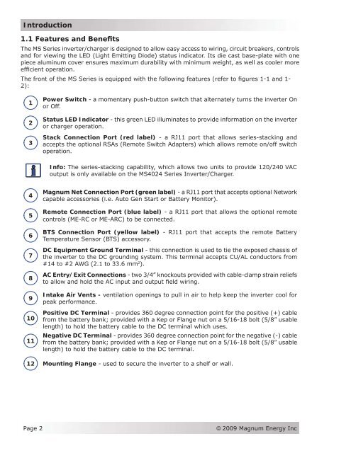
1.1 Features and Benefits<br />
The <strong>MS</strong> <strong>Series</strong> inverter/charger is designed to allow easy access to wiring, circuit breakers, controls<br />
and for viewing the LED (Light Emitting Diode) status indicator. Its die cast base-plate with one<br />
piece aluminum cover ensures maximum durability with minimum weight, as well as cooler more<br />
efficient operation.<br />
The front of the <strong>MS</strong> <strong>Series</strong> is equipped with the following features (refer to figures 1-1 and 1-<br />
2):<br />
1<br />
2<br />
3<br />
Power Switch - a momentary push-button switch that alternately turns the inverter On<br />
or Off.<br />
Status LED Indicator - this green LED illuminates to provide information on the inverter<br />
or charger operation.<br />
Stack Connection Port (red label) - a RJ11 port that allows series-stacking and<br />
accepts the optional RSAs (Remote Switch Adapters) which allows remote on/off switch<br />
operation.<br />
Info: The series-stacking capability, which allows two units to provide 120/240 VAC<br />
output is only available on the <strong>MS</strong>4024 <strong>Series</strong> Inverter/Charger.<br />
4<br />
5<br />
6<br />
7<br />
8<br />
9<br />
10<br />
11<br />
<strong>Magnum</strong> Net Connection Port (green label) - a RJ11 port that accepts optional Network<br />
capable accessories (i.e. Auto Gen Start or Battery Monitor).<br />
Remote Connection Port (blue label) - a RJ11 port that allows the optional remote<br />
controls (ME-RC or ME-ARC) to be connected.<br />
BTS Connection Port (yellow label) - RJ11 port that accepts the remote Battery<br />
Temperature Sensor (BTS) accessory.<br />
DC Equipment Ground Terminal - this connection is used to tie the exposed chassis of<br />
the inverter to the DC grounding system. This terminal accepts CU/AL conductors from<br />
#14 to #2 AWG (2.1 to 33.6 mm 2 ).<br />
AC Entry/Exit Connections - two 3/4” knockouts provided with cable-clamp strain reliefs<br />
to allow and hold the AC input and output field wiring.<br />
Intake Air Vents - ventilation openings to pull in air to help keep the inverter cool for<br />
peak performance.<br />
Positive DC Terminal - provides 360 degree connection point for the positive (+) cable<br />
from the battery bank; provided with a Kep or Flange nut on a 5/16-18 bolt (5/8” usable<br />
length) to hold the battery cable to the DC terminal which uses.<br />
Negative DC Terminal - provides 360 degree connection point for the negative (-) cable<br />
from the battery bank; provided with a Kep or Flange nut on a 5/16-18 bolt (5/8” usable<br />
length) to hold the battery cable to the DC terminal.<br />
12 Mounting Flange - used to secure the inverter to a shelf or wall.<br />
Page 2<br />
© 2009 <strong>Magnum</strong> <strong>Energy</strong> Inc