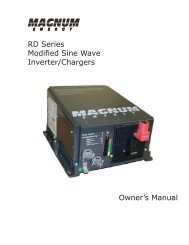
MS Series Owner's Manual - Magnum Energy
MS Series Owner's Manual - Magnum Energy
MS Series Owner's Manual - Magnum Energy
You also want an ePaper? Increase the reach of your titles
YUMPU automatically turns print PDFs into web optimized ePapers that Google loves.
Introduction<br />
1<br />
2<br />
3<br />
4<br />
5<br />
6<br />
POWER Power ON/OFF SWITCH Switch<br />
STATUS Status (Charging/Inverting) (CHARGING/INVERTING) LED LED<br />
STACK/ACCESSORIES Parallel Stack Port PORT<br />
(RED (red LABEL label - RJ11 – RJ45 CONNECTION) connector)<br />
NETWORK <strong>Magnum</strong> Net PORTPort<br />
(GREEN (green LABEL label - RJ11 – RJ11 CONNECTION) connector)<br />
REMOTE Remote PORT Port<br />
(BLUE (blue LABEL label - RJ11 – RJ11 CONNECTION) connector)<br />
BATTERY<br />
Battery<br />
TEMPERATURE<br />
Temp Sensor<br />
SENSOR<br />
Port<br />
PORT<br />
(YELLOW (yellow LABEL label - RJ11 – RJ11 CONNECTION) connector)<br />
Figure 1-1, Power Switch, Status LED and Accessory Connection Ports<br />
INTAKE Intake AIR VENTS<br />
(AND ON Air RIGHT Vents SIDE)<br />
(and on right side)<br />
9<br />
10<br />
Positive (+)<br />
DC Terminal<br />
(under TERMINAL cover)<br />
(UNDER COVER)<br />
POSITIVE (+) DC<br />
8<br />
AC ENTRY/EXIT Entry/Exit<br />
CONNECTIONS<br />
Connections<br />
7<br />
DC Equipment EQUIPMENT<br />
GROUND Ground<br />
TERMINAL<br />
Terminal<br />
11<br />
Negative (-)<br />
DC Terminal<br />
(under<br />
TERMINAL<br />
cover)<br />
(UNDER COVER)<br />
NEGATIVE (-) DC<br />
12<br />
Mounting MOUNTING<br />
Flange FLANGE<br />
Figure 1-2, Electrical Connection Points<br />
© 2009 <strong>Magnum</strong> <strong>Energy</strong> Inc.<br />
Page 3


