MS Series Owner's Manual - Magnum Energy
MS Series Owner's Manual - Magnum Energy
MS Series Owner's Manual - Magnum Energy

You also want an ePaper? Increase the reach of your titles
YUMPU automatically turns print PDFs into web optimized ePapers that Google loves.
Installation<br />
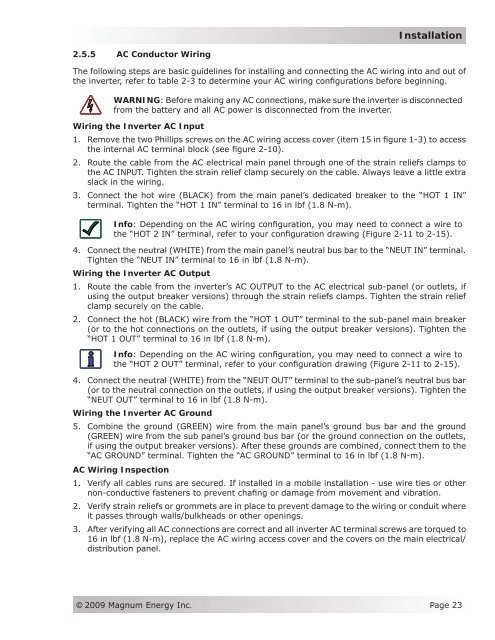
2.5.5 AC Conductor Wiring<br />
The following steps are basic guidelines for installing and connecting the AC wiring into and out of<br />
the inverter, refer to table 2-3 to determine your AC wiring configurations before beginning.<br />
WARNING: Before making any AC connections, make sure the inverter is disconnected<br />
from the battery and all AC power is disconnected from the inverter.<br />
Wiring the Inverter AC Input<br />
1. Remove the two Phillips screws on the AC wiring access cover (item 15 in figure 1-3) to access<br />
the internal AC terminal block (see figure 2-10).<br />
2. Route the cable from the AC electrical main panel through one of the strain reliefs clamps to<br />
the AC INPUT. Tighten the strain relief clamp securely on the cable. Always leave a little extra<br />
slack in the wiring.<br />
3. Connect the hot wire (BLACK) from the main panel’s dedicated breaker to the “HOT 1 IN”<br />
terminal. Tighten the “HOT 1 IN” terminal to 16 in lbf (1.8 N-m).<br />
Info: Depending on the AC wiring configuration, you may need to connect a wire to<br />
the “HOT 2 IN” terminal, refer to your configuration drawing (Figure 2-11 to 2-15).<br />
4. Connect the neutral (WHITE) from the main panel’s neutral bus bar to the “NEUT IN” terminal.<br />
Tighten the “NEUT IN” terminal to 16 in lbf (1.8 N-m).<br />
Wiring the Inverter AC Output<br />
1. Route the cable from the inverter’s AC OUTPUT to the AC electrical sub-panel (or outlets, if<br />
using the output breaker versions) through the strain reliefs clamps. Tighten the strain relief<br />
clamp securely on the cable.<br />
2. Connect the hot (BLACK) wire from the “HOT 1 OUT” terminal to the sub-panel main breaker<br />
(or to the hot connections on the outlets, if using the output breaker versions). Tighten the<br />
“HOT 1 OUT” terminal to 16 in lbf (1.8 N-m).<br />
Info: Depending on the AC wiring configuration, you may need to connect a wire to<br />
the “HOT 2 OUT” terminal, refer to your configuration drawing (Figure 2-11 to 2-15).<br />
4. Connect the neutral (WHITE) from the “NEUT OUT” terminal to the sub-panel’s neutral bus bar<br />
(or to the neutral connection on the outlets, if using the output breaker versions). Tighten the<br />
“NEUT OUT” terminal to 16 in lbf (1.8 N-m).<br />
Wiring the Inverter AC Ground<br />
5. Combine the ground (GREEN) wire from the main panel’s ground bus bar and the ground<br />
(GREEN) wire from the sub panel’s ground bus bar (or the ground connection on the outlets,<br />
if using the output breaker versions). After these grounds are combined, connect them to the<br />
“AC GROUND” terminal. Tighten the “AC GROUND” terminal to 16 in lbf (1.8 N-m).<br />
AC Wiring Inspection<br />
1. Verify all cables runs are secured. If installed in a mobile installation - use wire ties or other<br />
non-conductive fasteners to prevent chafing or damage from movement and vibration.<br />
2. Verify strain reliefs or grommets are in place to prevent damage to the wiring or conduit where<br />
it passes through walls/bulkheads or other openings.<br />
3. After verifying all AC connections are correct and all inverter AC terminal screws are torqued to<br />
16 in lbf (1.8 N-m), replace the AC wiring access cover and the covers on the main electrical/<br />
distribution panel.<br />
© 2009 <strong>Magnum</strong> <strong>Energy</strong> Inc.<br />
Page 23