AZ-225 Install Manual
AZ-225 Install Manual
AZ-225 Install Manual

Create successful ePaper yourself
Turn your PDF publications into a flip-book with our unique Google optimized e-Paper software.
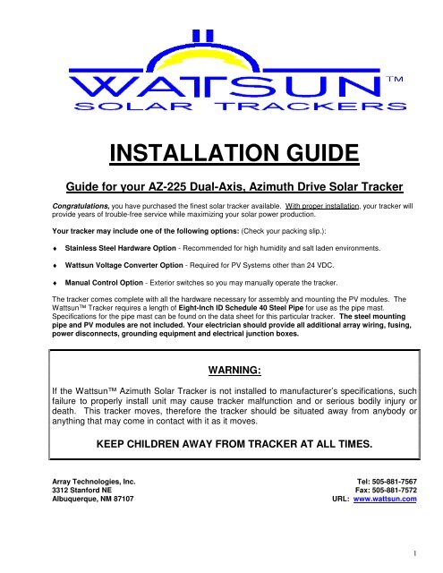
INSTALLATION GUIDE<br />
Guide for your <strong>AZ</strong>-<strong>225</strong> Dual-Axis, Azimuth Drive Solar Tracker<br />
Congratulations, you have purchased the finest solar tracker available. With proper installation, your tracker will<br />
provide years of trouble-free service while maximizing your solar power production.<br />
Your tracker may include one of the following options: (Check your packing slip.):<br />
♦ Stainless Steel Hardware Option - Recommended for high humidity and salt laden environments.<br />
♦ Wattsun Voltage Converter Option - Required for PV Systems other than 24 VDC.<br />
♦ <strong>Manual</strong> Control Option - Exterior switches so you may manually operate the tracker.<br />
The tracker comes complete with all the hardware necessary for assembly and mounting the PV modules. The<br />
Wattsun Tracker requires a length of Eight-Inch ID Schedule 40 Steel Pipe for use as the pipe mast.<br />
Specifications for the pipe mast can be found on the data sheet for this particular tracker. The steel mounting<br />
pipe and PV modules are not included. Your electrician should provide all additional array wiring, fusing,<br />
power disconnects, grounding equipment and electrical junction boxes.<br />
WARNING:<br />
If the Wattsun Azimuth Solar Tracker is not installed to manufacturer’s specifications, such<br />
failure to properly install unit may cause tracker malfunction and or serious bodily injury or<br />
death. This tracker moves, therefore the tracker should be situated away from anybody or<br />
anything that may come in contact with it as it moves.<br />
KEEP CHILDREN AWAY FROM TRACKER AT ALL TIMES.<br />
Array Technologies, Inc.<br />
3312 Stanford NE<br />
Albuquerque, NM 87107<br />
Tel: 505-881-7567<br />
Fax: 505-881-7572<br />
URL: www.wattsun.com<br />
1
Copyright © Array Technologies, Inc.<br />
All rights reserved.<br />
Wattsun is a trademark of Array Technologies, Inc.<br />
Sixteen, BP 150 watt modules mounted on a Wattsun <strong>AZ</strong>-<strong>225</strong> Tracker Drive.<br />
<strong>AZ</strong>-<strong>225</strong> <strong>Install</strong>ation Guide: Revision 5<br />
OCT 2008<br />
2
WARNING TO ELECTRICIAN OR INSTALLER<br />
♦ Please read this instruction manual completely.<br />
♦ If you are unfamiliar with NEC compliant solar electric installation, then<br />
consult with the dealer that supplied your tracker. They should have the<br />
skill and expertise to supply you with the necessary wiring diagrams and the<br />
appropriate connection wire, grounding equipment, junction boxes and fusing.<br />
♦ Failure to ground the array structure, including each module frame, the<br />
aluminum tracker frame, the drive head assembly and the pipe mast may<br />
make the tracker susceptible to damage by lightning.<br />
♦ Do not rely on the pipe mast to act as a ground rod. It is not a reliable<br />
substitute for a properly installed ground rod.<br />
♦ Please send in the Wattsun Tracker Warranty Card. Array Technologies<br />
does not share any of the information provided on the warranty card.<br />
♦ Please leave this manual for the tracker owner(s). It is their property and<br />
will help resolve any potential problems.<br />
♦ Please provide the following information for the owner:<br />
Serial Numbers: __________________________________<br />
Serial Number located on the controller<br />
______________________________________<br />
Serial Number located on the drive assembly<br />
Tracker Type: Dual-Axis Tracker is Standard on <strong>AZ</strong>-<strong>225</strong><br />
Controller is powered from: Battery Bank<br />
Power Supplu<br />
System Type: Off-Grid/Remote Home Grid-Intertie - no battery backup Grid-Intertie - battery backup<br />
Water Pumping<br />
Other _____________________<br />
PV Array: PV System Voltage is ______ VDC Number of Modules: __________<br />
Module Manufacturer: ____________<br />
Module Model: ____________<br />
Mounting Pole Height above the Ground is: ________ FT<br />
3
TABLE OF CONTENTS<br />
SECTION TITLE<br />
PAGE<br />
1 <strong>Install</strong>ation of the Tracker Pipe Mast and Foundation. 5<br />
2 <strong>Install</strong> the Azimuth Gear Drive Assembly on Top of the Pipe Mast 6<br />
3 <strong>Install</strong> the Fork Extensions, Torque Tube & Elevation Actuator 8<br />
4 <strong>Install</strong>ing the Module Support Frame 11<br />
5 <strong>Install</strong>ing a Wattsun Solar Tracker Controller 18<br />
6 Power Connection to the Elevation Actuator 25<br />
7 Power Connection to the Tracker Controller 26<br />
8 Setting Preferences and Operating the Tracker Controller 30<br />
9 Setting the <strong>AZ</strong> Motor Limits 32<br />
10 <strong>Manual</strong> Control Option 33<br />
11 Periodic Maintenance 34<br />
12 Suggested Methods for Grounding a Tracker 35<br />
13 Array Technologies, Inc. Limited Warranty 39<br />
4
Section<br />
1<br />
<strong>Install</strong>ation of Tracker Pipe Mast and Foundation<br />
WARNING! WINDY CONDITIONS CAN EXERT EXTREME FORCES ON THE ARRAY, FOUNDATION,<br />
AND PIPE MAST OF YOUR TRACKER.<br />
1.1) Choose an optimum solar location to install the PV array for in the ground mounting. The location should be<br />
free from obstructions. Keep in mind that over a period of time, that trees, shrubs, etc. may grow enough to<br />
obscure the PV array from the sun. Consult with your dealer for proper tracker spacing and alignment<br />
regarding multiple tracker installations.<br />
1.2) Dig an appropriate sized hole for your tracker’s foundation using a shovel, auger, or backhoe. The variables<br />
that affect the design of the foundation include: tracker size, pipe mast height, soil conditions, geographical<br />
location, weather and local building codes. Employ a qualified professional to design the foundation for your<br />
tracker.<br />
1.3) A general rule of thumb is to have an equal amount of pipe underground as above the ground and a three-foot<br />
diameter reinforced concrete foundation. Please have a professional design the size and type of foundation<br />
required!<br />
1.4) Use the appropriate length of 8" ID, Schedule 40 Steel Pipe in order to leave the recommended maximum<br />
pipe mast height protruding from ground. Consult your specific Wattsun Technical Data Sheet for the<br />
appropriate mast height and pipe diameter size. Note: If the recommended pipe mast height is exceeded, it<br />
may be necessary to telescope a larger diameter pipe in the lower portion and increase the foundation size in<br />
order to withstand the increased forces exerted during windy conditions.<br />
1.5) Cut at least two pieces of re-bar or steel angle (more with 8 module or larger trackers), at lengths equal to the<br />
full diameter of the foundation. Weld re-bar onto (or drill holes and insert re-bar into) the underground portion<br />
of the pipe so that the pieces of re-bar form an ‘x’ pattern that remains parallel to the ground. When the<br />
tracker pipe mast is completely installed, the re-bar will be perpendicular to the pipe and parallel to the ground<br />
and protrudes radially outward into the concrete foundation. The re-bar acts as an "anti-rotation" device and<br />
will keep the pipe from spinning in the hole if the concrete shrinks back from the pipe.<br />
1.6) Set the pipe into the hole and pour concrete around the pipe until it completely fills the hole. Also pour<br />
concrete into the pipe to secure the re-bar inserted in the bottom portion of pipe. Make certain the pipe is<br />
vertically plumb and allow concrete to set for at least 24 hours. If you fill the entire pipe mast with concrete,<br />
leave at least one foot of hollow pipe at top for azimuth drive assembly clearance.<br />
SIMPLIFIED TRACKER FOUNDATION DIAGRAM<br />
(Using recommended mast height from your Technical Data Sheet)<br />
Array Technologies, Inc. assumes no liability for your foundation installation.<br />
Please consult with a local professional or your Wattsun Solar Tracker Dealer.<br />
5
Section<br />
2<br />
<strong>Install</strong> the Azimuth Gear Drive Assembly<br />
On Top of the Pipe Mast<br />
2.1) Northern or Southern Hemisphere installations.<br />
For Northern Hemisphere installations, point the motor/gear assembly to ‘true north’ * and tighten the four<br />
set bolts to secure tracker to pipe mast. The set bolts should be tightened so that they dig into the pipe mast.<br />
For Southern Hemisphere locations, point the motor/gear assembly to ‘true south’ * and tighten the four set<br />
bolts to secure tracker to pipe mast. The set bolts should be tightened so that they dig into the pipe mast.<br />
Tropical and Equatorial <strong>Install</strong>ations are discussed in Section 3.5<br />
* Note:<br />
True north and south differ from magnetic north and south and depends on geographical location.<br />
Locate ‘magnetic north’ or ‘magnetic south’ using a compass and adjust your tracker setting<br />
accordingly. Your Wattsun Tracker Dealer can provide you with the Magnetic Declination for your<br />
area. The Array Technologies web site (www.wattsun.com) has links to geomagnetic data. You can<br />
find, or calculate, the magnetic declination for any place on the globe.<br />
Perhaps the easiest way to find the North-South line is to get a copy of your local newspaper and find<br />
the Sunrise and Sunset times. Determine the time (hour and minute) that falls exactly halfway<br />
between Sunrise and Sunset. At the halfway or 'Solar Noon' point, anything that casts a shadow will<br />
do so along a North-South line. Get a friend to help hold up a length of wood or a stick of conduit<br />
straight up into the sky. Then stake out or mark the North-South shadow line.<br />
6
VERY IMPORTANT! “OUT OF THE BOX” DRIVE ORIENTATION<br />
The <strong>AZ</strong>-<strong>225</strong> Drive orientation is preset at the factory and referenced to Solar Noon. The drive should<br />
be mounted facing due South, (Due North in the Southern Hemisphere.). The four set bolts “dig in” to<br />
the mounting pipe and secure the drive to the pipe mast.<br />
SET BOLTS: The 4 "cup point" set bolts "dig and cut" in to the 8" ID SCH40 Steel Pipe Mast. Tighten<br />
the set bolts so that they put strong and equal pressure on the pipe mast. Each bolt should "show"<br />
and equal amount of thread when you are finished. Each set bolt should be tightened to 100 Ft-<br />
Lbs of torque.<br />
ROLL PIN: A three-eighths inch (3/8") diameter hole is predrilled in the midpoint of the south face of<br />
the drive. The hole accommodates the 3/8" roll pin. Once you are sure that the drive is facing due<br />
South, you can use the hole as a guide to drill a three-eighths inch (3/8") diameter hole into and<br />
through the wall of the mounting pipe. Then tap in the roll pin so that it penetrates through both the<br />
drive and pipe mast. Alternately, both holes could be threaded and a bolt could be used to "pin" the<br />
drive and mounting pipe together.<br />
7
Section<br />
3<br />
<strong>Install</strong> the Fork Extensions, Torque Tube<br />
& Elevation Actuator<br />
BOLT THE FORK EXTENSIONS ONTO THE DRIVE<br />
(Most trackers are shipped from the factory with the lower fork extensions installed. Check the bolts to<br />
make sure that they did not loosen in transit.)<br />
Bolt the Lower Fork Extensions onto the <strong>AZ</strong>-<strong>225</strong> Drive. The forks angle downward and to the insides of the<br />
torque tube pivot holes on the drive. Each extension has two holes to secure it to the drive. That leaves a single<br />
hole at the end of each fork to bolt in the Elevation Actuator.<br />
WARNING!<br />
The <strong>AZ</strong>-<strong>225</strong> Drive weighs from 170 to 220 pounds!<br />
Do not use the Azimuth motor or tracker controller as<br />
“lift handles.” You will damage the motor gearing or<br />
tracker controller if you put any unusual force on<br />
them.<br />
You will have to be able to lift the <strong>AZ</strong>-<strong>225</strong> Drive up, over<br />
and down on top of your mounting pole. Placing the drive<br />
on top of the pipe is at least a “two person” job. The drive<br />
is much easier to set using a boom and pulley<br />
arrangement or suspending it from a backhoe bucket or<br />
other appropriate method.<br />
Make sure that the drive “seats” completely over the pipe.<br />
Back out the 4 set bolts and set aside if necessary to<br />
make sure that they do no catch on the top of the pipe.<br />
The 4 "cup point" set bolts "dig and cut" in to the steel<br />
pipe. Tighten the set bolts so that they put strong and<br />
equal pressure on the pipe mast. Each bolt should<br />
"show" an equal amount of thread when you are finished.<br />
Each set bolt should be tightened to 80 Ft-Lbs of<br />
torque.<br />
8
<strong>AZ</strong>-<strong>225</strong> HORIZONTAL TORQUE TUBE INSTALLATION FOR 4” X 4” TORQUE TUBE<br />
Consult the diagrams below for the bolt connections. Tighten the U-bolt Nylock nuts to 70 Ft-Lbs of torque<br />
TIGHTEN NYLOCK 5/16” U-BOLT NUTS EVENLY.<br />
TIGHTEN EACH NYLOCK NUT TO 70 FT-LBS OF TORQUE.<br />
<strong>AZ</strong>-<strong>225</strong> HORIZONTAL TORQUE TUBE INSTALLATION FOR 6” X 6” TORQUE TUBE<br />
Consult the diagrams below for the bolt connections. Tighten the channel-bolt Nylock nuts to 70 Ft-Lbs of torque<br />
9
ELEVATION ACTUATOR ASSEMBLY FOR DUAL-AXIS OPERATION:<br />
Do not unscrew the inner tube of the elevation actuator! This destroys the factory pre-set mechanical upper and<br />
lower limit switch settings. <strong>Install</strong> the elevation actuator. Center both the eyelet end (the top) of the elevation<br />
actuator inside the forks and the elevation actuator clamp eyelet (the bottom). Firmly tighten the locknuts on the<br />
bolt threads.<br />
UPPER CONNECTION<br />
LOWER CONNECTION<br />
Your tracker is shipped with a 36” stroke linear actuator. Make sure that the motor armature (can) is on the upper<br />
side of the actuator. That ensures that any moisture that might collect will drain out and away from the electrical<br />
connections.<br />
The actuator has a two cam-micro switch assembly that defines the limit of the<br />
extension and contraction. They are preset at the factory and there is no need to<br />
adjust them.<br />
Do not unscrew the inner tube of the actuator when you are installing it. It will disturb<br />
the limit switch presets.<br />
Do not change the location of the lower eye clamp. It is preset for your tracker. The<br />
clamp bolts have been pre-tightened to grip the body of the actuator securely. If you<br />
over tighten them, the clamp will deform the body of the outer tube. The<br />
deformations will cause scarring on the inner tube as it extends and withdraws.<br />
If you have special circumstances or concerns then please contact your distributor or<br />
Array technologies immediately.<br />
10
Section<br />
4<br />
<strong>Install</strong> the Module Support Frame Torque Tube<br />
SECTION 4 NOTES: Nearly every nut and bolt will be left "finger-tight" until all the modules are mounted and<br />
the frame is "squared-up." So allow for a small amount of "play" when putting the array together. You will<br />
snug up all the bolts and nuts when all the modules are mounted and the frame is complete.<br />
<strong>Install</strong>ation Tip: The PV modules may be mounted to the rails at this time - prior to installation onto the torque<br />
tube assembly. This removes the difficulty of mounting each individual module to the rails while you working<br />
off a ladder or above your head.<br />
However, placing the heavier, assembled module sub-array onto the torque tube assembly requires at least<br />
two people. For either application, the web of the module mounting struts must be oriented toward the outer<br />
ends of the modules.<br />
Procedure for <strong>Install</strong>ing Solar Modules on Wattsun Tracker Universal Rails<br />
Examples of Three and Four Column Tracker Frames<br />
Wattsun Tracker frames are manufactured to hold the solar modules in a rectangular grid. A pair of vertical<br />
module rails will mount a group of modules in “landscape” format.<br />
The completed frame is made up of one to four pairs of module rails.<br />
Each rail is u-bolted onto the horizontal “steel spine” of the tracker called a torque tube. If the rails they are longer<br />
than ten feet then an additional support under-angle is included – one for each rail. Wattsun Trackers come with<br />
all the hardware to assemble the tracker and mount the modules.<br />
The end user supplies the appropriate mounting pipe and engineered foundation.<br />
11
BUILDING THE FRAME AND RACKING THE MODULES:<br />
DO YOU MOUNT ONE PIECE AT A TIME OR BUILD SUB-ARRAYS?<br />
Module Rail & Support Angle Detail<br />
From the bottom up the Procedure is:<br />
Bolt > Support Angle > Tube > Rail >Washer > Nut<br />
One installer, one piece at a time approach.<br />
Modules are being used to “square-up: the frame.<br />
Notice how the modules overhang the Rails.<br />
Sub-Array Approach: Requires a lot of people power.<br />
Notice that the rails bolt to the intermediate module holes.<br />
Lift by the tracker rails only, not the module frames!<br />
Lifting and bolting the sub-array onto the tube.<br />
Typically a 3-person job: 2 lifters, 1 bolter.<br />
Lift by the tracker rails only, not the module frames!<br />
The “one piece at a time” approach can get very tiring. The<br />
installer is working with their arms and hands above their head.<br />
We encourage installers’ to wear a Hard Hat.<br />
Leave all frame and module bolts “finger tight.” Once you finish<br />
the frame building and module mounting, you can go back and<br />
“square up” the array. Then tighten all nuts with a wrench.<br />
NOTE: If you ever “under populate” the array frame, leave<br />
any unused space at the top of the frame. If the frame is<br />
not totally filled out, then the greatest weight should be on<br />
the lower sections of the frame.<br />
12
Tools Required: Frame Assembly and Module Mounting<br />
Tool<br />
Required to Fasten<br />
3/4 “ Open End Wrench Nylock Nuts for the Module Rail Assembly U-Bolt<br />
7/16” Open End Wrench Flange Nut for 1/4” x 3/4” Module Mounting Bolt<br />
1/2 ” Open End Wrench Flange Nut for 5/16” x 3/4” Module Mounting Bolt<br />
Rubber or Plastic Head Mallet<br />
Small adjustments to shift the Rail Assembly sideways<br />
Step 1<br />
The modules get mounted to the rails using the<br />
intermediate holes. Locate the intermediate<br />
mounting holes on the frame of your module.<br />
In general, they are placed from 7” to 16” in on the<br />
long side (Length) when measured from the frame<br />
edge short side (Width).<br />
Each manufacturer has unique hole patterns. Your<br />
mounting holes are made to accommodate either<br />
1/4” or 5/16” module mounting bolts. The bolts are<br />
supplied with your Wattsun Tracker.<br />
Step 2<br />
Identify your module mounting bolts and nuts from<br />
the hardware kit. The module bolts are labeled and<br />
are either 1/4” or 5/16” diameter.<br />
Note that both the interior faces of the nut and bolt<br />
are made to cut into the module frame. They do not<br />
require any type of washer.<br />
13
Step 3<br />
There are four bolts and nuts per module. Premount<br />
the module bolts so that the serrated nuts will<br />
dig into the underside of the module frame.<br />
Do not tighten the bolt fully. Leave it about one full<br />
turn loose so it will glide easily in the module track.<br />
Step 4<br />
Measure and record the “center to center” distance<br />
of the intermediate mounting holes. This dimension<br />
sets the spacing of the mounting rails.<br />
Each pair of mounting rails typically holds from 3 to 4<br />
large modules. Typical rail spacing might be from<br />
24” to 35” apart.<br />
Step 5<br />
Remove a pair of modules rails from the frame<br />
bundle. They will be bolted on top of the torque tube<br />
so that the “legs” of the channel face inward towards<br />
each other.<br />
The bolts on in the top track are the module<br />
fasteners and the bolts in the side track secure the<br />
module rail support angle.<br />
( Cross section view of the<br />
module rails and bolt connections )<br />
14
Step 6<br />
Pull the module rail u-bolts, washers and locknuts<br />
from the hardware kit. There will be one set of u-bolt<br />
hardware per module rail.<br />
If your module rail is longer than 10 feet then there<br />
will be a corresponding support angle in your frame<br />
bundle.<br />
Step 7<br />
If you have a three column tracker<br />
(3 modules wide) then your first rail set will be<br />
centered over the drive head and straddle the<br />
centerline of the torque tube.<br />
If you have a four column tracker ( 4 modules wide)<br />
then your first rail set will be to the right or left of the<br />
centerline of the torque tube.<br />
(Step 1)<br />
Step 8<br />
Pass the u-bolt through the holes in the support<br />
angle. Push the u-bolt up and around the torque tube<br />
and into the receiving holes in the bottom of the<br />
module rail.<br />
Place a 1/2” flat washer over each leg of the u-bolt<br />
and then secure a 1/2” Nylock nut over each leg. Do<br />
not tighten the Nylock nut completely. Leave a little<br />
slack so the rail assembly can be slid horizontally<br />
along the torque tube to accommodate your “center<br />
to center” measurement.<br />
(Step 4)<br />
15
Step 9<br />
Carefully fold up the support angle so that it makes<br />
contact with the underside of the module rail. The<br />
hole in the side face of the angle should be aligned<br />
over the side track of the module rail.<br />
The support angle connection to the side of the<br />
module requires that you slide a 5/16” bolt along the<br />
side track until it aligns with the hole in the end of the<br />
support angle.<br />
Do not tighten the bolt completely. Leave a little<br />
slack so you can square up the frame at the end of<br />
the installation.<br />
Step 10<br />
Use a tape measure and gap the module rails a<br />
distance equal to the “center to center” intermediate<br />
hole spacing. (Step 4)<br />
Be sure that you are spacing from the centers of<br />
both top tracks in the rails. You might have to loosen<br />
the u-bolt Nylock nuts so that you can easily adjust<br />
the rail assembly along the torque tube.<br />
The racked modules and frame will be squared up at<br />
the end of the mounting procedure.<br />
Step 11<br />
Make sure that the tracker is in the “stow” or nearly<br />
horizontal position and that the elevation bar or<br />
actuator has been installed.<br />
Line up the module bolts into each track. You might<br />
have to spin the bolt a bit so that the square shoulder<br />
of the bolt line up in the slot. Push the module<br />
forward and repeat the process with the other side of<br />
the module.<br />
Once the module is properly positioned on the rails,<br />
tighten the serrated module nuts until they are finger<br />
tight.<br />
16
Step 12<br />
Continue populating the array with the rail<br />
assemblies and solar modules. Even out the<br />
spacing between the module frames (typically 1/4” in<br />
1/2”) and square-up the frame assembly. Go back<br />
and tighten up all the bolts and nusts left intentionally<br />
loose.<br />
Start with the rail assembly u-bolts Nylock nuts, then<br />
proceed to the support angle fasteners (if provided)<br />
and finish up with each module mounting bolt and<br />
nut.<br />
17
Section<br />
5<br />
<strong>Install</strong>ing the Wattsun Solar Tracker Controller<br />
WARNING! PLEASE READ THIS GUIDE COMPLETELY BEFORE CONNECTING POWER TO THE<br />
CONTROLLER. YOU CAN DAMAGE THE CONTROLLER OR INADVERTANTLY POWER UP THE TRACKER<br />
AND CREATE A H<strong>AZ</strong>ARDOUS SITUATION. NEVER APPLY POWER TO THE CONTROLLER OUTPUT<br />
WIRES! THE CONTROLLER WILL BE DAMAGED AND THE REPAIR CHARGE IS NOT COVERED UNDER<br />
WARRANTY.<br />
For <strong>Install</strong>ations in the Tropics:<br />
(20 degrees North latitude to 20 degrees South latitude)<br />
Array Technologies does not encourage the use of Dual-Axis Trackers in “low latitudes.” Wattsun Single-<br />
Axis Trackers are preferred in the tropics. Contact Array Technologies for performance data and<br />
recommendations.<br />
The azimuth tracker works by rotating the PV array about the pipe mast then tilting the array to the proper<br />
elevation angle. Therefore, for installations near the equator it will be necessary to rotate the azimuth tracker 180<br />
degrees twice a year. Depending upon the time of year, trackers in this region will find the sun anywhere from<br />
north, south, or directly overhead of its location, making manual rotation necessary.<br />
For example, at the equator rotation of the tracker will need to occur on the first day of spring and the first day of<br />
fall. The array should point north on March 21st, and rotated 180 degrees to point south on September 23rd.<br />
To rotate the tracker on the pipe mast, loosen the four set bolts on the azimuth drive, rotate the tracker and retighten.<br />
Marking the pipe mast for the two yearly positions, aids in seasonal adjustment. You must also leave<br />
sufficient output wire lengths from the array to allow for rotation.<br />
24 VOLT TRACKER CONTROLLER SPECIFICATIONS<br />
Controller input power specifications:<br />
The input voltage range is 23 to 50 volts DC.<br />
Use a Wattsun Voltage adapter to power the controller for nominal voltages other than 24 VDC.<br />
Tracker controller wiring and drive motor wiring:<br />
Do not connect the motor output wire harness to a power source! Connecting any of the controller output<br />
wires to the PV array or a power source will cause permanent damage to the controller and void the<br />
warranty.<br />
Power supply connection options:<br />
The input power leads are Red (positive) and Black (negative) wires in the two-wire cable mounted on the<br />
left-hand side of the controller chassis. The input wires are clearly marked with a tag.<br />
Power consumption, including motors:<br />
Less than 10 watt-hours per day.<br />
18
Y<br />
OUR TRACKER CONTROLLER IS PREINSTALLED ON THE <strong>AZ</strong>-<strong>225</strong> DRIVE.<br />
WARNING!<br />
MAKE THE “POWER IN” CONNECTION LAST!<br />
DO NOT ENERGIZE THE WATTSUN SOLAR TRACKER CONTROLLER UNTIL YOU HAVE COMPLETED<br />
THE ENTIRE TRACKER INSTALLATION.<br />
TWO ADDITIONAL CONTROLLER CONNECTIONS THAT GET MADE BY THE INSTALLER:<br />
Sensor mounts on the top edge of the array.<br />
Center it on the top to make for a neat wire<br />
run. The remote sensor wire plugs into the<br />
base of the sensor. Twist the lock ring!<br />
There is a two-wire “pig-tail”<br />
that is prewired into the<br />
azimuth motor. It needs to be<br />
connected to the elevation<br />
actuator motor.<br />
19
WATTSUN TRACKER CONTROLLER: FUNCTION AND FEATURES.<br />
OVERVIEW<br />
Wattsun Solar Trackers utilize a patented, closed loop, optical sensing system to sense the sun’s position<br />
and track it. The sun sensors are mounted on the remote chassis and feed information to the control<br />
electronics about the direct component of sunlight available, the diffuse amount of sunlight, the total amount<br />
of sunlight as well as the differential amount of sunlight on opposing sensors. Based on this information, the<br />
controller seeks to equalize the sunlight received by opposing sensors for each axis.<br />
The controller circuitry automatically adjusts the tracker sensitivity. It increases the sensitivity with increased<br />
direct sunlight and decreases the sensitivity with scattered or diffused light - present during cloudy<br />
conditions. This enables the tracker to eliminate undue hunting in cloudy or overcast conditions when the<br />
sunlight is scattered. It also adjusts according to the total amount of light received by the sensors.<br />
When the tracker controller is connected to a battery bank or constant power source, the controller senses<br />
sunset and returns to the sunrise position. When it is powered directly from the PV array, the tracker returns<br />
to sunrise at first morning light. The controller uses energy integration circuitry, enabling the tracker to move<br />
with as little as 20ma of available current.<br />
The tracker controller sends a signal to the DC gear motor that moves the PV array to a perpendicular<br />
position relative to the sun’s rays. The motors are small, fraction HP, low voltage, gear motors that move the<br />
tracker into position. The gearing is designed such that high winds or other forces cannot drive the tracker<br />
back. Because they are DC drive motors, one polarity moves them in the forward direction and reversing the<br />
polarity moves them in the opposite direction. When the controller wants the tracker to move, it sends a<br />
signal of the appropriate polarity to the DC gear-motor. Once the tracker has moved to the “on track”<br />
position, the controller electrically “brakes” the motor to stop movement that results in greater tracking<br />
accuracy.<br />
STANDARD FEATURES OF YOUR WATTSUN CONTROLLER<br />
♦ Controller mounted on the drive for maximum accessibility.<br />
♦ Sensor mounts independently of the main chassis.<br />
♦ Dip switches to test the Azimuth and Elevation Limits.<br />
♦ Dip switch to set nighttime Elevation (stow) position.<br />
♦ Controller outputs are short circuit protected and will limit the output current to 3 amps.<br />
♦ Inside controller chassis are light sensitivity adjustment potentiometers for Azimuth and Elevation.<br />
♦ Controller is equipped with a 5-amp automotive spade type fuse (ATO) inside the controller chassis.<br />
♦ Self-resetting thermal fuse that shuts off power to the tracker motors in case of obstruction.<br />
♦ Filtering to protect the tracker motor against "noisy" PWM charge controllers.<br />
♦ Improved lightning protection.<br />
DUAL-AXIS NOTES<br />
The controller prioritizes the azimuth (east/west) axis. If the azimuth axis is not on track, the elevation axis will<br />
not function. Once the azimuth axis has locked onto the sun and stops moving, the elevation axis adjusts.<br />
However, if you power the controller from a battery bank, you can choose to allow simultaneous azimuth and<br />
elevation motion.<br />
NOTE<br />
The Array Direct method is not recommended for powering Azimuth-Drive Trackers. You can easily lose of<br />
the available 30% of a long summer day!<br />
20
Terminal Controller Output Motor<br />
1 White Azimuth Drive<br />
2 Green Azimuth Drive<br />
3 Red Elevation Actuator<br />
4 Black Elevation Actuator<br />
21
5.1) THE <strong>AZ</strong>MUTH MOTOR TERMINAL STRIP (PRE-WIRED AT THE FACTORY)<br />
It is unlikely that you will need to access the wiring inside the Azimuth Motor. The Azimuth Motor Terminal<br />
Strip is pre-wired at the factory. It serves as a central connection point for motor power wires. The 4-wire<br />
Controller output lead and the Elevation Actuator lead share entry into the Azimuth Motor Cover through<br />
the rain tight plastic strain relief.<br />
A four-wire lead enters in from the Controller and is divided into two pairs. The first pair (White & Green)<br />
controls the East-West Azimuth movement. The second pair (Red & Black) “passes through” and controls<br />
the North-South elevation movement. The Elevation Actuator power lead exits azimuth motor cover<br />
through the strain relief and will be connected to the actuator motor by the installer.<br />
.<br />
<strong>AZ</strong>-<strong>225</strong> <strong>AZ</strong>IMUTH MOTOR WIRE CONNECTIONS<br />
22
<strong>AZ</strong>IMUTH MOTOR: TERMINAL STRIP WIRING DIAGRAM<br />
(POWER CONNECTIONS ARE PREWIRED AT THE FACTORY)<br />
WARNING!<br />
THE LAST CONNECTION MADE IS FROM YOUR POWER SOURCE TO THE TRACKER CONTROLLER! DO<br />
NOT ENERGIZE THE WATTSUN SOLAR TRACKER CONTROLLER UNTIL YOU HAVE COMPLETED THE<br />
ENTIRE TRACKER INSTALLATION.<br />
23
5.2) MOUNTING THE REMOTE SENSOR<br />
MOUNT THE REMOTE SENSOR ON THE TOP OF THE ARRAY<br />
The sensor mounts on the TOP CENTER (or near the center) of the PV array. Most modules already<br />
have a hole in the frame that you can use. If your modules do not have an "end hole" then you will need to<br />
drill a 1/4" hole in the frame to mount the sensor. Slip a thin piece of wood between the module frame and<br />
the back of the module. The wood "spacer" will keep you from inadvertently digging your drill bit into the<br />
back of the module once you have drilled through the frame.<br />
If the modules in your array mount in “landscape” format and you have aluminum “endcaps” at the top and<br />
bottom of the array, then use the endcap mounting bolt and a strut near the center of the tracker. Make sure<br />
that the sensor has a clear view of the sky.<br />
The wire coming from the sensor has a molded connector. It mates into the bottom of the controller. The<br />
controller connector has a grove inside to properly align the mating pieces. Match up the “tongue and<br />
groove” of both connectors, push them together and twist the locking ring to secure the connection.<br />
THE V3.3 SENSOR ORIENTATION IS DIFFERENT FROM THE EARLIER V3.x VERSIONS!<br />
The sensor needs to be above the plane of the array and have a<br />
clear view to the sky. Do not crowd it against the array or module<br />
frame. If the “eyes” don’t have the freedom to see the sun then<br />
the tracker will behave oddly. The sensors function is to make<br />
sure that equal amounts of light fall on all four sides.<br />
Be careful not to damage the clear sensor on top. It’s function<br />
controls “return to the east” at night.<br />
24
Section<br />
6<br />
Power Connection to the Elevation Actuator<br />
Warning! Never apply power to the actuator until it has been securely bolted into place. The linear<br />
actuator will tend to "unscrew" and will destroy the preset limit switch settings.<br />
6.1) Loosen the cover screws and remove the actuator cover. The plastic strain relief might have been inverted<br />
to protect it during shipping and hidden inside the actuator cover. Flip it around, reseat and snake the<br />
actuator power wire through the strain relief.<br />
WVW-VEN36” Linear Actuator<br />
TOP Terminal 1 Controller Red to Actuator Red<br />
BOT. Terminal 2 Controller Black to Actuator Black<br />
The actuator motors are DC motors. The polarity of the DC power coming from the controller will dictate the<br />
direction and movement of the actuator. Standard DC color codes are “relative” when applied to the actuator<br />
motor connections.<br />
DC input polarity during normal operation<br />
Extension ( Tilt Array Up ) Red + Black -<br />
Retraction ( Lay Array Flat ) Red - Black +<br />
.<br />
25
Section<br />
7<br />
Power Connection to the Tracker Controller<br />
7.1) MAKING A DECISION ABOUT POWERING THE WATTSUN CONTROLLER<br />
NOTE: The azimuth-tracking limit switches are preset at the factory to accommodate the maximum<br />
range of East-West azimuth tracking.<br />
OPTION 1: Array Technologies recommends that you power your Wattsun Tracker Controller from a battery<br />
bank or grid-tied power source. The tracker will return to the East at sunset and the tracker has 270 degrees<br />
of azimuth tracking available. The dip-switch, sensor override features built into the controller are always<br />
available when you have constant power.<br />
OPTION 2: (Discouraged with the <strong>AZ</strong>-SeriesTrackers!) If you power the controller from the array, the<br />
tracker returns East in the morning. The tracker is limited to only 180 degrees of azimuth tracking arc. You<br />
will have to reset the Azimuth Motor limit switch cams to reduce the East-West travel. The dip-switch,<br />
sensor override features built into the controller will only be available during the day.<br />
The diagram shows the hourly sun position for 40 Degrees North Latitude. During the winter, a tracker that<br />
is powered from an array returns in the morning and captures nearly all the 117-degree azimuth-tracking arc.<br />
However, during the summer, 242-degree azimuth-tracking arc is available. A tracker that is powered from<br />
an array only captures a 180-degree portion of that arc, and proportionally less power too - even if the<br />
tracker limits are set to their extremes.<br />
7.2) On most Azimuth Trackers, the controller is already mounted to the drive head at the factory. The remote<br />
sensor and azimuth motor connections are already pre-wired and tested.<br />
Your installer should provide the appropriate fusing or DC breaker to protect any long wire runs and<br />
to disconnect to the controller power input.<br />
26
7.3) POWER OPTION #1: POWER CONTROLLER FROM A CONSTANT POWER SOURCE:<br />
(24 OR 48 VOLT DC BATTERY BANK OR GRID-TIED AC TO DC SWITCHING POWER SUPPLY)<br />
♦ Powering the tracker controller from a battery bank or Grid-Tied Switching Power Supply is the<br />
RECOMMENDED WAY to provide power to your Wattsun Tracker Controller.<br />
♦ The controller power-input leads can be connected directly to the main 24-volt battery bank.<br />
♦ The tracker returns to the East at sunset and has 270 degrees of azimuth tracking available. The dipswitch,<br />
sensor override features built into the controller are always available when you have battery<br />
power.<br />
♦ If the installation is for a 48-volt system, then you should use a Wattsun Voltage 48 to 24 VDC<br />
Converter to reduce the voltage to the tracker controller and motors.<br />
♦ If the installation is for a “Battery-Less” Grid-Tie System, then you should use a Wattsun Switching<br />
Power Supply (WPS5RSF-24 or equivalent) to convert AC voltage to 24 VDC.<br />
♦ The positive lead running from the battery bank, to the power input of the controller, should be fused<br />
with a 5 amp, current limiting, DC-rated fuse or equivalent DC breaker.<br />
♦ Failure to fuse the input power wire at the battery bank may create a potential fire hazard.<br />
WARNING! Do not power the controller directly from a 48 VDC battery bank. The "working voltage"<br />
of a 48 VDC bank exceeds the controller's 50 VDC maximum input rating. A 48 VDC bank can easily<br />
reach 59 VDC during an equalize cycle.<br />
SIMPLIFIED WIRING DIAGRAM FOR BATTERY BANK TO CONTROLLER CIRCUIT<br />
27
7.4) POWER OPTION #2: POWER THE CONTROLLER FROM A 24 or 48 VOLT PV ARRAY<br />
(Array Technologies does not recommend array-direct power connection for Azimuth trackers.<br />
Contact your Dealer for assistance if you are using 24 VDC nominal modules with MC Connectors.)<br />
♦ Array-direct power limits the daily azimuth tracker rotation to 180 degrees or less.<br />
♦ If the installation is for a 48-volt system, then you should use a Wattsun Voltage Converter to reduce<br />
the voltage to the tracker controller and motors.<br />
♦ The positive lead running from the battery bank, to the power input of the controller, should be fused<br />
with a 5 amp, current limiting, DC-rated fuse or equivalent DC breaker.<br />
♦ Failure to fuse the input power wire at the array may create a potential fire hazard.<br />
The input power leads should be connected to a 24-volt nominal PV array. Typically, this will be the output<br />
of two 12-volt PV modules in series. The input voltage should never exceed 50 volts DC and will only<br />
operate when the input voltage is above 23 volts. If the 50 VDC maximum is exceeded, the controller will<br />
be damaged. The damage is not covered under warranty.<br />
Typical Open Circuit Voltage, or Voc, of a 24 VDC array is 44 VDC. A 48 VDC nominal array has a Voc of<br />
88 VDC. Array Technologies manufactures a voltage adapter for PV arrays with voltages over 24 VDC.<br />
Please contact your Dealer if you need the adapter.<br />
When the controller is powered directly from the PV array, the tracker returns to the east in the morning.<br />
The tracker controller automatically adapts to whatever current is available from the PV array. If the PV<br />
array is only capable of producing small amounts of current (20 to 300 milliamps) the tracker will move in<br />
small, pulsed increments. When the array provides over 1/3 an amp (300 ma) of current, the array moves<br />
in a smooth fashion. Typical full east return should occur within 15 minutes after sunrise.<br />
Powering the controller from the array should only be used when limiting the tracker rotation to 180<br />
degrees or less. If the rotation of the tracker is set greater than 180 degrees or if the tracker is not pointed<br />
true South, the tracker will be slow to return to the sunrise position in the morning.<br />
BASIC WIRING DIAGRAM FOR ARRAY DIRECT TO CONTROLLER<br />
28
CONTROLLER DIAGRAM, COMPONENTS, SWITCH SETTINGS AND FUSING<br />
Interior View of a Dual-Axis Controller for Azimuth Trackers<br />
DIP SWITCH SETTINGS<br />
Dip Default Up Position Down Position<br />
#1 Down Freeze Tracker - Temporary off only Normal: Auto Track<br />
#2 Up Normal: Energy Integration ON:<br />
Allow for low current sources to power the<br />
tracker controller.<br />
charge 24 VDC battery.<br />
#3 Up Normal: Prioritize Azimuth Axis.<br />
Move Azimuth 1 st , Elevation 2 nd .<br />
Freeze Elevation at night.<br />
Energy Integration OFF: Lowers the voltage<br />
input threshold to power from a low state of<br />
Move Azimuth and Elevation at the same<br />
time and lay the tracker flat at night.<br />
(5 Degree tilt).<br />
#4 Down Disable Elevation Actuator Auto Track<br />
(Winter mode: Maintain a steep tilt to shed snow)<br />
#5 Down <strong>Manual</strong>ly move East. Normal: Auto Track.<br />
#6 Down <strong>Manual</strong>ly move West. Normal: Auto Track.<br />
#7 Down <strong>Manual</strong>ly move North. Normal: Auto Track.<br />
#8 Down <strong>Manual</strong>ly move South. Normal: Auto Track.<br />
Normal: Dual-Axis Tracking ON<br />
DIP SWITCH<br />
Small rocker switches that affect controller operation. Switches 5,6,7 & 8 move the tracker: allow for a 3 second<br />
delay for the motors to engage after “throwing” a switch from Auto Tracking. Return to the Normal position for<br />
Auto Tracking!<br />
LIGHT SENSITIVITY TRIM POTS<br />
Inside the controller chassis are two adjustment potentiometers for light sensitivity. They are a single-turn pot:<br />
clock-wise rotation equals greater sensitivity, counter clock-wise rotation equals lower sensitivity. This adjustment<br />
is factory pre-set and should only be adjusted by qualified personnel. Do not turn more than ½ turn in either<br />
direction!<br />
INTERIOR FUSE<br />
Replaceable 5-Amp automotive spade type fuse (ATO). Do not replace with a larger amp rated fuse! Gently pull<br />
the fuse out of the holder to inspect or replace. It is usual to see a small spark when reconnecting the fuse. A 7.5-<br />
Amp fuse is the maximum fuse allowed. A 10-Amp fuse or higher will cause trouble!<br />
29
Section<br />
8<br />
Setting Preferences and Operating<br />
the Tracker Controller<br />
OVERVIEW: OPERATING THE TRACKER CONTROLLER AND SETTING THE DIP SWITCH OPTIONS.<br />
Your tracker controller is preinstalled and “ready to go” as soon as you connect power it. The following procedure<br />
tests the controllers operation, the full range of motion of the tracker and to set some field selectable options. You<br />
can turn the tracker on and off or choose to bypass the Energy Integration Circuit. If you have a Dual-Axis tracker,<br />
you can make the tracker lay nearly flat at night or disable the auto-tilt function entirely.<br />
8.1) Survey your work area: You are going to test the tracker range of motion. Be aware that your tracker is set<br />
to Auto-Track and will start moving as soon as power is connected to the controller!<br />
Make sure that there in nothing in the way of the tracker when it begins to rotate. A common mistake is to<br />
leave a ladder standing nearby. Inspect the wiring from the array to the controller and your junction box.<br />
Make sure that all wire service loops are long enough and that the wires are free from binding at all pivot<br />
points. Is there enough slack in the wires to accommodate full azimuth rotation in either direction?<br />
8.2) Remove the controller cover: Loosen the 4 Phillips bit machine screws and remove the metal cover of the<br />
controller. Keep the cover and gasket free of dirt.<br />
8.3) Switch#1- Auto Tracking: ON when pushed in at the bottom. Depress the top rocker of Dip Switch #1 to<br />
the UP position to temporarily freeze the tracker position. Push in at the bottom to return to Auto Tracking<br />
when you are finished testing the controller.<br />
8.4) Switch #2- Energy Integration: ON when pushed in at the top. Always Leave UP (E.I. ON) unless you are<br />
powering the tracker from a nearly depleted 24VDC battery bank. The down position (E.I. OFF) bypasses the<br />
Energy Integration Circuitry. This allows the tracker to operate when the battery voltage is below 23.5 VDC<br />
8.5) Switch #3 – Dual Axis, Maintain Array Tilt at Night: ON when pushed in at the bottom. The Azimuth Drive<br />
motor operates 1 st and the Elevation actuator operates 2 nd . At night, the array maintains a steep tilt. When<br />
the switch is pushed in at the bottom, both tracker motors can operate at the same time and the array will<br />
LAY FLAT at night. Use only in situations where there are high winds and no snow during the evening hours.<br />
8.6) Switch #4: Dual Axis, Elevation Tracking: ON when pushed in at the bottom. The tracker will<br />
automatically track the sun up and down in the sky. OFF when the switch is pushed in at the top, the<br />
elevation tracking is stopped. Use in high-latitude sites where the days are short, the sun is low in the sky<br />
and snow loading on the array is an issue.<br />
8.7) Switch #5: EAST OVERRIDE OFF when pushed in at the bottom. <strong>Manual</strong>ly move the tracker East by<br />
depressing the top of Dip Switch #5. The tracker will track to the East and then stop once the Limit<br />
Adjustment Cam touches the limit switch. Return it to OFF position for AUTO TRACKING.<br />
8.8) Switch #6: WEST OVERRIDE OFF when pushed in at the bottom. <strong>Manual</strong>ly move the tracker West by<br />
depressing the top of Dip Switch #6. The tracker will track to the West and then stop once the Limit<br />
Adjustment Cam touches the limit switch. Return it to OFF position for AUTO TRACKING.<br />
8.9) Switch #7: NORTH OVERRIDE OFF when pushed in at the bottom. <strong>Manual</strong>ly move the tracker North (deelevate)<br />
by depressing the top of Dip Switch #7. The tracker will "flatten out" and stop once the elevation<br />
actuator's internal limit has been reached. Return it to OFF position for AUTO TRACKING.<br />
8.10) Switch #8: SOUTH OVERRIDE OFF when pushed in at the bottom. <strong>Manual</strong>ly move the tracker South<br />
(elevate) by depressing the top of Dip Switch #8. The tracker will track to the North and then stop once the<br />
elevation actuator's internal limit has been reached. Return it to OFF position for AUTO TRACKING.<br />
8.11) Setting the Sensor Light Sensitivity: The sensor sensitivity is preset at the factory. Inside the controller<br />
chassis are two adjustment potentiometers for light sensitivity. They are a single-turn pot: clockwise rotation<br />
equals greater sensitivity, counter-clockwise rotation equals lower sensitivity. Only qualified personnel<br />
should perform this adjustment. Do not turn more than ½ turn in either direction!<br />
30
VIEW OF A DUAL-AXIS CONTROLLER with V3.3 Sensor<br />
31
Section<br />
9<br />
Setting the <strong>AZ</strong> Motor Limits<br />
KEEP YOUR FINGERS AND TOOLS AWAY FROM THE GEARING BENEATH THE PROTECTIVE COVER OF<br />
THE DRIVE!<br />
The limits for your tracker are preset at the factory. Please contact Array Technologies if you want to change your<br />
settings.<br />
However, for clarification please review the images below. There are two cams: one stacked atop the other. The<br />
bottom cam controls the East limit and the top cam controls the West limit. As the tracker motor operates and<br />
moves the tracker, the cams rotate too. Eventually, a "nub" on the cam contacts a limit switch and stops the<br />
tracker. The tracker is free to rotate in the opposite direction if the sensor tells it to or if you are in the manual<br />
control mode.<br />
The East cam is preset to the maximum East (wide open) position at the factory and acts as a reference for the<br />
West cam. The cams are held and meshed together with a retaining spring. Rotate the West cam (top cam)<br />
clockwise decrease the westward travel of the array. Make your adjustments in small increments. And always<br />
Test the range of motion after making any adjustment!<br />
Do not exceed 135 degrees of rotation West of South or the Worm Gear Assembly will hit a welded safety stop. If<br />
you hit the stop the tracker motors will draw too much current and a self-resetting fuse in the controller will shut off<br />
the power to the azimuth motor. Turn the tracker controller off using Dip Switch #1, let the fuse cool for 3 minutes,<br />
adjust the West cam to reduce the west travel and flip Dip Switch #1 back to the normal operating position.<br />
Repeat this process if necessary.<br />
Always test the tracker range of motion after adjusting the cams! Then test it again!<br />
32
Section<br />
10<br />
<strong>Manual</strong> Control Option<br />
FUNCTION:<br />
Most manual controls are installed on Wattsun Dual-Axis Trackers rather than on Single-Axis Units.<br />
The <strong>Manual</strong> Control Option allows the user to bypass automatic tracking and to move the tracker East,<br />
West, North, or South. The <strong>Manual</strong> Control Option is typically installed on your tracker before it leaves<br />
Array Technologies. However it is available as an upgrade kit that can be installed in the field.<br />
The <strong>Manual</strong> Control Option requires that power be available to the Wattsun Tracker Controller. If the<br />
controller is connected to the main battery bank, then you can use the manual controls day or night. If<br />
you power the tracker controller from the array, then you will be limited to the daylight hours.<br />
HIGH WIND AREAS:<br />
If the tracker is run to a full North position, the array lays flat in a horizontal stow position. This is<br />
especially useful if you experience very strong winds or tropical storms and you want to reduce the<br />
wind loading on your tracker.<br />
HIGH SNOW AREAS:<br />
If the tracker is run to a full South position, the array elevates up to a 75-degree angle. This is useful<br />
for dumping any snow accumulation on the array.<br />
SWITCHES:<br />
Automatic / <strong>Manual</strong> - Flip Down for Auto Tracking or flip Up to enable <strong>Manual</strong> Tracking.<br />
East / West - Hold left to track East or hold right to track West.<br />
North / South - Hold up to track South (elevate) or hold down to track North (flatten).<br />
33
Section<br />
11<br />
Periodic Maintenance<br />
12) PERIODIC MAINTENANCE<br />
♦ Maintenance should be performed at least once a year. More often if your tracker is installed in severe<br />
weather areas.<br />
♦ Inspect all the tracker hardware and the module bolts for tightness. Tighten all nuts and bolts that need it.<br />
♦ Inspect all wires for abrasion and gently tug on them to make sure that they are secure.<br />
♦ Each of the four grease zerks should receive 4-6 pumps of lithium-base general-purpose chassis grease from<br />
a grease gun.<br />
♦ Elevation Actuator: Spray the inner tube (telescoping part) of the linear actuator with a lubricating rust inhibitor.<br />
(We use LPS-3)<br />
NOTE:<br />
YOUR <strong>AZ</strong>-<strong>225</strong> GEAR DIVE MAY HAVE THE 4 th GREASE ZERK LOCATED ON THE BOTTOM OF THE GEAR<br />
HOUSING RATHER THAN THE TOP AS SHOWN IN THE PICTURE.<br />
34
Section<br />
12<br />
Suggested Methods for Grounding a Tracker<br />
WARNING!<br />
• The information provided here is a general guideline for grounding your<br />
Wattsun Solar Tracker.<br />
• This information is not a substitute for following the National Electrical<br />
Code.<br />
• You should hire a qualified Electrician, Electrical Contractor or Solar<br />
Professional to install and wire your Wattsun Solar Tracker.<br />
• Array Technologies does not assume any liability for your failure to adhere<br />
to the NEC.<br />
• Failure to ground your tracker may void your Wattsun Warranty and may<br />
result in damage to your Wattsun Solar Tracker Controller or motors.<br />
WATTSUN TRACKER RAILS ARE COMPATIBLE WITH WEEB 9.5<br />
GROUNDING WASHERS.<br />
http://www.we-llc.com/WEEB.html<br />
GROUNDING REFERENCE:<br />
John Wiles - Code Corner Columns available online at:<br />
http://www.nmsu.edu/%7Etdi/Photovoltaics/Codes-Stds/codecorner.html<br />
35
FIG 1: GROUNDING THE MODULES, TRACKER FRAME, DRIVE AND MOUNTING PIPE<br />
The array equipment-grounding conductors, for the modules, tracker frame, drive and mounting-pipe, should<br />
terminate at one location—probably a grounding terminal strip in the junction/combiner box. Then, there should be<br />
a conductor from this point to the grounding electrode (ground rod).<br />
The steps are:<br />
• The frame of every module is interconnected with grounding wire.<br />
• The module grounding wire ties into the tracker frame on the torque tube or struts.<br />
• A flexible loop of grounding wire continues from the torque tube to the base of the drive.<br />
• The ground wire continues to the mounting pipe or combiner box that is bonded to the pipe.<br />
• The ground wire goes down the pole and is bonded to an 8-foot copper ground rod.<br />
• The ground rod is set in the earth outside of the concrete foundation of the pipe.<br />
• Do not rely on the mounting pipe to act as a ground rod.<br />
(Older <strong>AZ</strong>200 shown for illustration purposes)<br />
36
FIG 2: TYPICAL GROUNDING OF A TRACKER TO THE BATTERY BANK/POWERCENTER.<br />
• The modules, Wattsun Tracker, and mounting pipe are grounded as shown in Figure 1.<br />
• The normal, (primary bond) negative-to-ground bonding is required in the power center or ground-fault<br />
device.<br />
• The negative current-carrying (PV Negative) conductor is bonded (connected) to the grounding system at<br />
the power center or charge controller.<br />
• An equipment-grounding conductor is run from the PV array to the power center or charge controller.<br />
WARNING!<br />
If you ground according to FIG 2, you must ground the PV Negative at the power center, not at the array. There<br />
can only be one ground for the current carrying conductor (PV Negative) in this situation.<br />
37
FIG 3: ALTERNATIVE GROUNDING FOR A TRACKER THAT IS DISTANT FROM THE BATTERY<br />
BANK/POWERCENTER.<br />
• The modules, Wattsun Tracker, and mounting pipe are grounded as shown in Figure 1.<br />
• The PV array is ground mounted some distance (perhaps over 30 feet) away from other PV components<br />
(inverter, batteries, etc.). The distance is not specified in the NEC.<br />
• There are no AC power circuits between the array and the bank/power center.<br />
• There are no conductive paths (electrical or other) such as water pipes, metal fences, communication<br />
circuits, or telephone circuits between the array and the other structure.<br />
• Bond the negative conductor (PV Negative) to the grounding system at both the array and at the<br />
inverter/battery/power center location.<br />
• Do not run any equipment grounding conductors between the array and at the inverter/battery/power<br />
center location.<br />
• Use ground rods at the array and at the inverter/battery/power center location.<br />
WARNING!<br />
If you ground according to FIG 3, you must ground the PV Negative at both the array and at the powercenter. Do<br />
not run any equipment grounding conductors between the array and at the inverter/battery/power center location.<br />
38
Section<br />
13<br />
Array Technologies, Inc. Limited Warranty<br />
Array Technologies, Inc. warrants its Wattsun Solar Trackers to the original consumer purchaser that it will<br />
repair, or replace, at Array Technologies Inc.’s option, any Wattsun Tracker component that is determined to be<br />
defective in material or workmanship for the following terms:<br />
Two years from date of purchase on all components including tracker controller, frame, azimuth drive<br />
assembly, and actuator.<br />
To be eligible for repair or replacement under this warranty, the part in question must be sent to Array<br />
Technologies, Inc. within the warranty period and the original consumer purchaser must comply with the following<br />
conditions:<br />
♦ The tracker or component thereof must not have been modified or altered in any way by an unauthorized<br />
source.<br />
♦ The tracker or component thereof must have been installed in accordance with the installation instructions<br />
including electrical connections of tracking controller.<br />
This limited warranty does not cover:<br />
♦ Damage due to improper or installation;<br />
♦ Accidental or intentional damage;<br />
♦ Misuse, abuse, corrosion, or neglect;<br />
♦ Products impaired by severe conditions, such as excessive wind, ice, storms or other natural occurrences;<br />
♦ Trackers used for purposes other than the intended use, including mounting modules or components which<br />
the tracker was not intended for;<br />
♦ Trackers with more than the intended number and type of modules mounted on it;<br />
♦ Damage due to improper packaging on return shipment.<br />
Any and all labor charges for troubleshooting, removal or replacement of tracker and/or components of<br />
the tracker are not covered by this warranty and will not be honored by Array Technologies, Inc.<br />
Return shipping is to be pre-paid by the original consumer purchaser. Array Technologies, Inc. will pay the normal<br />
return UPS shipping charges within the USA only.<br />
THIS WARRANTY IS EXPRESSLY IN LIEU OF ALL OTHER WARRANTIES OF ANY KIND, EXPRESSED OR<br />
IMPLIED, INCLUDING (WITHOUT LIMITATION) ANY IMPLIED WARRANTIES OF MERCHANTABILITY OR<br />
FITNESS FOR A PARTICULAR PURPOSE, AND OF ANY NONCONTRACTUAL LIABILITIES BASED UPON<br />
NEGLIGENCE OR STRICT LIABILITY. IN NO EVENT SHALL ARRAY TECHNOLOGIES, INC. BE LIABLE FOR<br />
INCIDENTAL OR CONSEQUENTIAL DAMAGES, INCLUDING (WITHOUT LIMITATIONS) ANY DAMAGE FOR<br />
PERSONAL INJURY OR PROPERTY DAMAGE OR OTHER PRODUCT LIABILITIES BASED UPON ALLEGED<br />
NEGLIGENCE OR BREACH OF EXPRESS OR IMPLIED WARRANTIES OR STRICT LIABILITY. ARRAY<br />
TECHNOLOGIES, INC. NEITHER ASSUMES NOR AUTHORIZES ANY OTHER PERSON TO ASSUME FOR IT<br />
ANY OTHER OBLIGATION IN CONNECTION WITH THE SALE OF ITS WATTSUN SOLAR TRACKERS.<br />
THIS WARRANTY GIVES YOU SPECIFIC LEGAL RIGHTS, AND YOU ALSO MAY HAVE OTHER RIGHTS<br />
THAT MAY VARY FROM STATE TO STATE. SOME STATES DO NOT ALLOW LIMITATIONS ON HOW LONG<br />
AN IMPLIED WARRANTY WILL LAST OR THE EXCLUSION OR LIMITATION OF INCIDENTAL OR<br />
CONSEQUENTIAL DAMAGES, SO THE ABOVE LIMITATIONS OR EXCLUSIONS MAY NOT APPLY TO YOU.<br />
Array Technologies, Inc.<br />
3312 Stanford NE<br />
Albuquerque, NM 87107<br />
Tel: 505-881-7567<br />
Fax: 505-881-7572<br />
URL: www.wattsun.com<br />
39