AZ-225 Install Manual
AZ-225 Install Manual
AZ-225 Install Manual

Create successful ePaper yourself
Turn your PDF publications into a flip-book with our unique Google optimized e-Paper software.
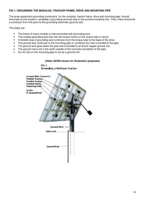
FIG 1: GROUNDING THE MODULES, TRACKER FRAME, DRIVE AND MOUNTING PIPE<br />
The array equipment-grounding conductors, for the modules, tracker frame, drive and mounting-pipe, should<br />
terminate at one location—probably a grounding terminal strip in the junction/combiner box. Then, there should be<br />
a conductor from this point to the grounding electrode (ground rod).<br />
The steps are:<br />
• The frame of every module is interconnected with grounding wire.<br />
• The module grounding wire ties into the tracker frame on the torque tube or struts.<br />
• A flexible loop of grounding wire continues from the torque tube to the base of the drive.<br />
• The ground wire continues to the mounting pipe or combiner box that is bonded to the pipe.<br />
• The ground wire goes down the pole and is bonded to an 8-foot copper ground rod.<br />
• The ground rod is set in the earth outside of the concrete foundation of the pipe.<br />
• Do not rely on the mounting pipe to act as a ground rod.<br />
(Older <strong>AZ</strong>200 shown for illustration purposes)<br />
36