AZ-225 Install Manual
AZ-225 Install Manual
AZ-225 Install Manual

Create successful ePaper yourself
Turn your PDF publications into a flip-book with our unique Google optimized e-Paper software.
Section<br />
6<br />
Power Connection to the Elevation Actuator<br />
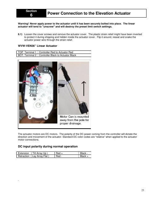
Warning! Never apply power to the actuator until it has been securely bolted into place. The linear<br />
actuator will tend to "unscrew" and will destroy the preset limit switch settings.<br />
6.1) Loosen the cover screws and remove the actuator cover. The plastic strain relief might have been inverted<br />
to protect it during shipping and hidden inside the actuator cover. Flip it around, reseat and snake the<br />
actuator power wire through the strain relief.<br />
WVW-VEN36” Linear Actuator<br />
TOP Terminal 1 Controller Red to Actuator Red<br />
BOT. Terminal 2 Controller Black to Actuator Black<br />
The actuator motors are DC motors. The polarity of the DC power coming from the controller will dictate the<br />
direction and movement of the actuator. Standard DC color codes are “relative” when applied to the actuator<br />
motor connections.<br />
DC input polarity during normal operation<br />
Extension ( Tilt Array Up ) Red + Black -<br />
Retraction ( Lay Array Flat ) Red - Black +<br />
.<br />
25