AZ-225 Install Manual
AZ-225 Install Manual
AZ-225 Install Manual

Create successful ePaper yourself
Turn your PDF publications into a flip-book with our unique Google optimized e-Paper software.
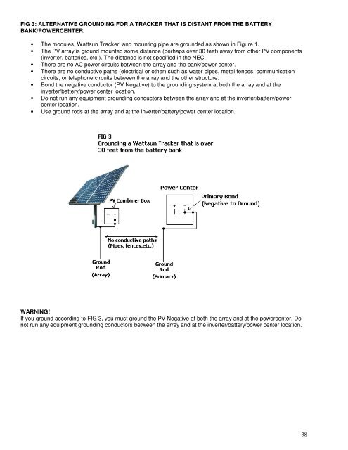
FIG 3: ALTERNATIVE GROUNDING FOR A TRACKER THAT IS DISTANT FROM THE BATTERY<br />
BANK/POWERCENTER.<br />
• The modules, Wattsun Tracker, and mounting pipe are grounded as shown in Figure 1.<br />
• The PV array is ground mounted some distance (perhaps over 30 feet) away from other PV components<br />
(inverter, batteries, etc.). The distance is not specified in the NEC.<br />
• There are no AC power circuits between the array and the bank/power center.<br />
• There are no conductive paths (electrical or other) such as water pipes, metal fences, communication<br />
circuits, or telephone circuits between the array and the other structure.<br />
• Bond the negative conductor (PV Negative) to the grounding system at both the array and at the<br />
inverter/battery/power center location.<br />
• Do not run any equipment grounding conductors between the array and at the inverter/battery/power<br />
center location.<br />
• Use ground rods at the array and at the inverter/battery/power center location.<br />
WARNING!<br />
If you ground according to FIG 3, you must ground the PV Negative at both the array and at the powercenter. Do<br />
not run any equipment grounding conductors between the array and at the inverter/battery/power center location.<br />
38