AZ-225 Install Manual
AZ-225 Install Manual
AZ-225 Install Manual

You also want an ePaper? Increase the reach of your titles
YUMPU automatically turns print PDFs into web optimized ePapers that Google loves.
Section<br />
9<br />
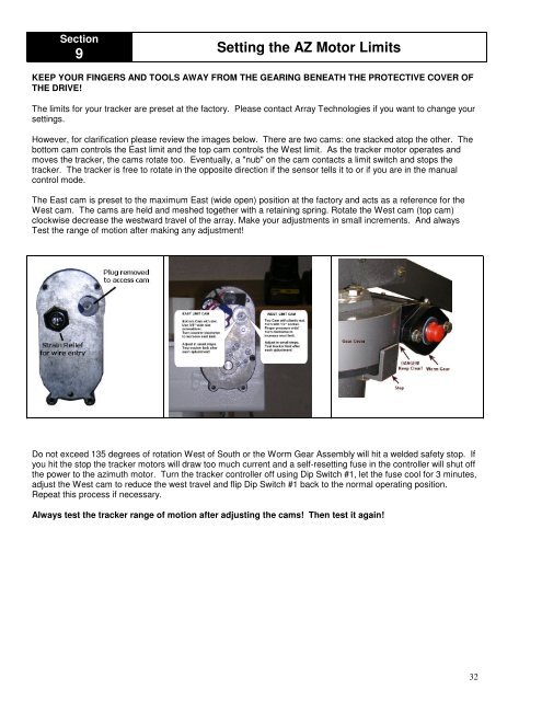
Setting the <strong>AZ</strong> Motor Limits<br />
KEEP YOUR FINGERS AND TOOLS AWAY FROM THE GEARING BENEATH THE PROTECTIVE COVER OF<br />
THE DRIVE!<br />
The limits for your tracker are preset at the factory. Please contact Array Technologies if you want to change your<br />
settings.<br />
However, for clarification please review the images below. There are two cams: one stacked atop the other. The<br />
bottom cam controls the East limit and the top cam controls the West limit. As the tracker motor operates and<br />
moves the tracker, the cams rotate too. Eventually, a "nub" on the cam contacts a limit switch and stops the<br />
tracker. The tracker is free to rotate in the opposite direction if the sensor tells it to or if you are in the manual<br />
control mode.<br />
The East cam is preset to the maximum East (wide open) position at the factory and acts as a reference for the<br />
West cam. The cams are held and meshed together with a retaining spring. Rotate the West cam (top cam)<br />
clockwise decrease the westward travel of the array. Make your adjustments in small increments. And always<br />
Test the range of motion after making any adjustment!<br />
Do not exceed 135 degrees of rotation West of South or the Worm Gear Assembly will hit a welded safety stop. If<br />
you hit the stop the tracker motors will draw too much current and a self-resetting fuse in the controller will shut off<br />
the power to the azimuth motor. Turn the tracker controller off using Dip Switch #1, let the fuse cool for 3 minutes,<br />
adjust the West cam to reduce the west travel and flip Dip Switch #1 back to the normal operating position.<br />
Repeat this process if necessary.<br />
Always test the tracker range of motion after adjusting the cams! Then test it again!<br />
32