AZ-225 Install Manual
AZ-225 Install Manual
AZ-225 Install Manual

You also want an ePaper? Increase the reach of your titles
YUMPU automatically turns print PDFs into web optimized ePapers that Google loves.
Section<br />
5<br />
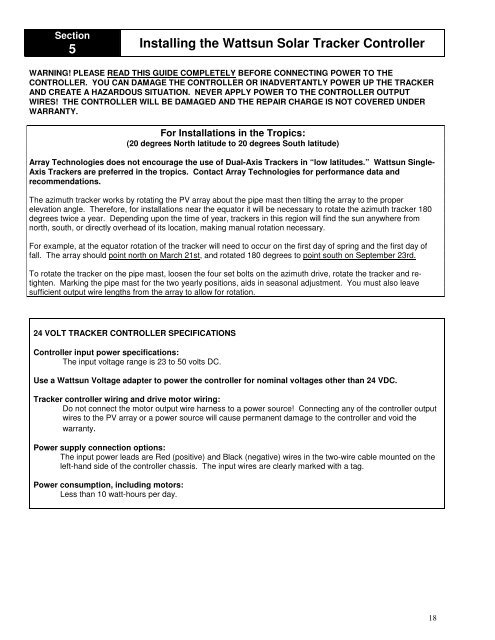
<strong>Install</strong>ing the Wattsun Solar Tracker Controller<br />
WARNING! PLEASE READ THIS GUIDE COMPLETELY BEFORE CONNECTING POWER TO THE<br />
CONTROLLER. YOU CAN DAMAGE THE CONTROLLER OR INADVERTANTLY POWER UP THE TRACKER<br />
AND CREATE A H<strong>AZ</strong>ARDOUS SITUATION. NEVER APPLY POWER TO THE CONTROLLER OUTPUT<br />
WIRES! THE CONTROLLER WILL BE DAMAGED AND THE REPAIR CHARGE IS NOT COVERED UNDER<br />
WARRANTY.<br />
For <strong>Install</strong>ations in the Tropics:<br />
(20 degrees North latitude to 20 degrees South latitude)<br />
Array Technologies does not encourage the use of Dual-Axis Trackers in “low latitudes.” Wattsun Single-<br />
Axis Trackers are preferred in the tropics. Contact Array Technologies for performance data and<br />
recommendations.<br />
The azimuth tracker works by rotating the PV array about the pipe mast then tilting the array to the proper<br />
elevation angle. Therefore, for installations near the equator it will be necessary to rotate the azimuth tracker 180<br />
degrees twice a year. Depending upon the time of year, trackers in this region will find the sun anywhere from<br />
north, south, or directly overhead of its location, making manual rotation necessary.<br />
For example, at the equator rotation of the tracker will need to occur on the first day of spring and the first day of<br />
fall. The array should point north on March 21st, and rotated 180 degrees to point south on September 23rd.<br />
To rotate the tracker on the pipe mast, loosen the four set bolts on the azimuth drive, rotate the tracker and retighten.<br />
Marking the pipe mast for the two yearly positions, aids in seasonal adjustment. You must also leave<br />
sufficient output wire lengths from the array to allow for rotation.<br />
24 VOLT TRACKER CONTROLLER SPECIFICATIONS<br />
Controller input power specifications:<br />
The input voltage range is 23 to 50 volts DC.<br />
Use a Wattsun Voltage adapter to power the controller for nominal voltages other than 24 VDC.<br />
Tracker controller wiring and drive motor wiring:<br />
Do not connect the motor output wire harness to a power source! Connecting any of the controller output<br />
wires to the PV array or a power source will cause permanent damage to the controller and void the<br />
warranty.<br />
Power supply connection options:<br />
The input power leads are Red (positive) and Black (negative) wires in the two-wire cable mounted on the<br />
left-hand side of the controller chassis. The input wires are clearly marked with a tag.<br />
Power consumption, including motors:<br />
Less than 10 watt-hours per day.<br />
18