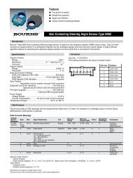
Non-Contacting Multiturn Angle Sensor Type 6000 - we.CONECT
Non-Contacting Multiturn Angle Sensor Type 6000 - we.CONECT
Non-Contacting Multiturn Angle Sensor Type 6000 - we.CONECT

You also want an ePaper? Increase the reach of your titles
YUMPU automatically turns print PDFs into web optimized ePapers that Google loves.
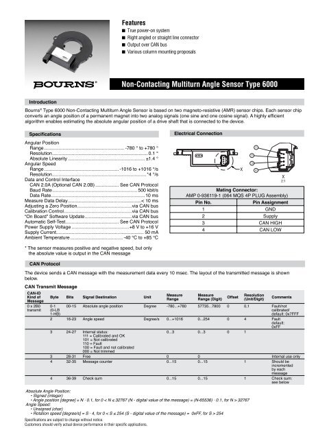
Features<br />
■ True po<strong>we</strong>r-on system<br />
■ Right angled or straight line connector<br />
■ Output over CAN bus<br />
■ Various column mounting proposals<br />
<strong>Non</strong>-<strong>Contacting</strong> <strong>Multiturn</strong> <strong>Angle</strong> <strong>Sensor</strong> <strong>Type</strong> <strong>6000</strong><br />
Introduction<br />
Bourns ® <strong>Type</strong> <strong>6000</strong> <strong>Non</strong>-<strong>Contacting</strong> <strong>Multiturn</strong> <strong>Angle</strong> <strong>Sensor</strong> is based on two magneto-resistive (AMR) sensor chips. Each sensor chip<br />
converts an angle position of a permanent magnet into two analog signals (one sine and one cosine signal). A highly effi cient<br />
algorithm enables estimating the absolute angular position of a drive shaft that is connected to the device.<br />
Specifications<br />
Angular Position<br />
Range ............................................................. -780 ° to +780 °<br />
Resolution ......................................................................... 0.1 °<br />
Absolute Linearity ........................................................... ±1.4 °<br />
Angular Speed<br />
Range ......................................................... -1016 to +1016 °/s<br />
Resolution ........................................................................*4 °/s<br />
Data and Control Interface<br />
CAN 2.0A (Optional CAN 2.0B) .................. See CAN Protocol<br />
Baud Rate ................................................................. 500 kbit/s<br />
Data Rate........................................................................10 ms<br />
Measure Data Delay ........................................................< 10 ms<br />
Adjusting a Zero Position..........................................via CAN bus<br />
Calibration Control ....................................................via CAN bus<br />
“On Board” Software Update ....................................via CAN bus<br />
Automatic Self-Test......................................... See CAN Protocol<br />
Po<strong>we</strong>r Supply Voltage ............................................+8 V to +16 V<br />
Supply Current................................................................... 50 mA<br />
Ambient Temperature ........................................ -40 °C to +85 °C<br />
Electrical Connection<br />
PBT<br />
X<br />
2<br />
3<br />
1<br />
4<br />
X<br />
2:1<br />
Mating Connector:<br />
AMP 0-936119-1 (064 MQS 4P PLUG Assembly)<br />
Pin No.<br />
Pin Assignment<br />
1 GND<br />
2 Supply<br />
3 CAN HIGH<br />
4 CAN LOW<br />
* The sensor measures positive and negative speed, but only<br />
the absolute value is output in the CAN message<br />
CAN Protocol<br />
The device sends a CAN message with the measurement data every 10 msec. The layout of the transmitted message is shown<br />
below.<br />
CAN Transmit Message<br />
CAN-ID<br />
Kind of<br />
Message<br />
0 x 2B0<br />
transmit<br />
Byte Bits Signal Destination Unit<br />
0-1<br />
(0-LB<br />
1-HB)<br />
Specifi cations are subject to change without notice.<br />
Customers should verify actual device performance in their specifi c applications.<br />
Measure<br />
Range<br />
Measure<br />
Range (Digit)<br />
Offset<br />
Resolution<br />
(Unit/Digit)<br />
Comments<br />
00-15 Absolute angle position Degree -780...+780 57735...7800 0 0,1 Fault/not<br />
calibrated/<br />
default: 0x7FFF<br />
2 16-23 <strong>Angle</strong> speed Degree/s 0...+1016 0...254 0 4 Fault<br />
default:<br />
0xFF<br />
3 24-27 Internal status:<br />
0...3 0...3 0 1<br />
111 = Calibrated and OK<br />
101 = Not calibrated<br />
110 = Fault<br />
100 = Fault and not calibrated<br />
000 = Not trimmed<br />
3 28-31 Free 0 0 Internal use only<br />
4 32-35 Message counter 0...15 0...15 1 Should be<br />
incremented<br />
by each<br />
message<br />
4 36-39 Check sum 0...15 0...15 1 Check sum:<br />
see below<br />
Absolute <strong>Angle</strong> Position:<br />
• Signed (integer)<br />
• <strong>Angle</strong> position [degree] = N · 0.1, for 0 < N ≤ 32767 (N - digital value of the message) = (N-65536) · 0.1, for N > 32767<br />
<strong>Angle</strong> Speed:<br />
• Unsigned (char)<br />
• Rotation speed [degree/s] = S · 4, for 0 < S ≤ 254 (S - digital value of the message) = 0xFF, for S > 254
<strong>Non</strong>-<strong>Contacting</strong> <strong>Multiturn</strong> <strong>Angle</strong> <strong>Sensor</strong> <strong>Type</strong> <strong>6000</strong><br />
CAN Protocol (Continued)<br />
Rule to build the check sum:<br />
Temp_result = lo<strong>we</strong>r byte<br />
(<strong>Angle</strong> position) XOR higher byte<br />
(<strong>Angle</strong> position) XOR (<strong>Angle</strong> speed)<br />
XOR<br />
(Internal status)<br />
Check sum = higher nibble<br />
(Temp_result) XOR lo<strong>we</strong>r nibble<br />
(Temp_result) XOR (Message counter)<br />
Automatic Self-Test<br />
The device checks the angular speed<br />
value, which is limited to 1016 degrees per<br />
second. If this limit exceeded, the device<br />
sends an error message according to the<br />
CAN Transmit Message (page 1).<br />
The device is also able to receive messages. They are shown below.<br />
CAN Receive Message<br />
CAN-ID<br />
Kind of<br />
Message Byte Bits Signal Destination Unit Measure<br />
Range<br />
0x7C0 0 0-3 Command word<br />
receive<br />
0 4-7 SAS transmit identifi er<br />
(SAS ID) bits 0-3<br />
1 8-14 SAS transmit identifi er<br />
(SAS ID) bits 4-10<br />
1 15 Free<br />
Measure<br />
Range<br />
(Digit)<br />
Offset<br />
Resolution<br />
(Unit/Digit)<br />
Comments<br />
Command Word (CW)<br />
CW bit3 CW bit2 CW bit1 CW bit0 Instruction<br />
0 0 1 1 Set up the zero position<br />
0 1 0 1 Clear the old zero position<br />
Other combinations<br />
Only for internal use<br />
Note:<br />
To set up a new zero position, fi rst it is necessary to delete the old zero position.<br />
Design and Mechanical Interface<br />
Housing - Device View<br />
0°<br />
+ -<br />
14.5 50.5<br />
28<br />
DELIVERING<br />
STATUS<br />
DIMENSIONS: MM<br />
Specifi cations are subject to change without notice.<br />
Customers should verify actual device performance in their specifi c applications.
-<br />
<strong>Non</strong>-<strong>Contacting</strong> <strong>Multiturn</strong> <strong>Angle</strong> <strong>Sensor</strong> <strong>Type</strong> <strong>6000</strong><br />
Typical Test Results @ R.T.<br />
The fi rst graph shows a typical linearity measurement curve taken at room temperature. The second graph shows the deviation (absolute nonlinearity)<br />
over four turns of the steering wheel.<br />
Output Code and Absolute Linearity<br />
800<br />
0.3<br />
600<br />
0.2<br />
400<br />
0.1<br />
200<br />
0<br />
0<br />
-0.1<br />
-200<br />
-400<br />
-0.2<br />
-600<br />
-0.3<br />
-800 -0.4 -800 -700 -600 -500 -400 -300 -200 -100 0 100 200 300 400 500 600 700 800 -800 -700 -600 -500 -400 -300 -200 -100 0 100 200 300 400 500 600 700 800<br />
Definition of Output Signal According to Rotation of Steering Wheel<br />
+<br />
TURN LEFT<br />
TURN RIGHT<br />
+780 °<br />
DIGITAL OUTPUT<br />
0 °<br />
+780 °<br />
0 °<br />
STEERING WHEEL ANGLE<br />
-780 °<br />
-780 °<br />
Europe:<br />
Bourns <strong>Sensor</strong>s GmbH<br />
Robert-Bosch-Str. 14<br />
D-82054 Sauerlach<br />
Phone: +49 (0) 8104 646-0<br />
The Americas:<br />
Bourns, Inc.<br />
1660 N. Opdyke Road, Ste. 200<br />
Auburn Hills, MI 48326-2655 USA<br />
Phone: +1 248 926-4088<br />
Asia:<br />
Bourns, Inc.<br />
10F, No. 146, Sung Jiang Road<br />
Taipei, Taiwan, 104 PRC<br />
Phone: +886 2 2562-4117<br />
www.bourns.com<br />
automotive@bourns.com<br />
REV. 01/12<br />
Specifi cations are subject to change without notice.<br />
Customers should verify actual device performance in their specifi c applications