MDA / LDA / TDA Series - Dynisco Instruments
MDA / LDA / TDA Series - Dynisco Instruments
MDA / LDA / TDA Series - Dynisco Instruments

You also want an ePaper? Increase the reach of your titles
YUMPU automatically turns print PDFs into web optimized ePapers that Google loves.
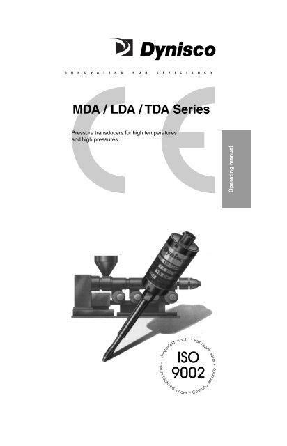
<strong>MDA</strong> / <strong>LDA</strong> / <strong>TDA</strong> <strong>Series</strong><br />
Pressure transducers for high temperatures<br />
and high pressures<br />
Operating manual<br />
1
Table of Contents<br />
Content<br />
Chapter<br />
Page<br />
Icon<br />
General<br />
1<br />
3<br />
Notes on safety<br />
2<br />
5<br />
Technical data<br />
3<br />
6<br />
Function<br />
4<br />
14<br />
Transport/<br />
delivery<br />
5<br />
16<br />
Assembly<br />
6<br />
17<br />
Commissioning<br />
7<br />
24<br />
Maintenance<br />
8<br />
26<br />
Accessories<br />
9<br />
28<br />
Troubleshooting<br />
10<br />
29<br />
- Declaration of<br />
conformity<br />
11<br />
30<br />
2
1. General<br />
1.1 Important information 3<br />
1.2 Copyright 3<br />
1.3 Explanation of icons 4<br />
1.4 Abbreviations 4<br />
1.5 Correct use 4<br />
1.6 User’s obligations 4<br />
1.1 Important information<br />
This manual applies to the <strong>MDA</strong> 420/460/435/467, PT<br />
420/460, <strong>TDA</strong> 432/463 and <strong>LDA</strong> 415 series only. It<br />
must be kept near the equipment in a readily and<br />
immediately accessible location at all times.<br />
The content of this manual must be read, understood<br />
and followed in all points by all relevant people. This<br />
applies in particular to the notes on safety. Following<br />
the safety instructions will help to prevent accidents,<br />
defects and malfunctions.<br />
DYNISCO will not be held liable for any injury, loss or<br />
damage resulting from failure to follow the instructions<br />
in this manual.<br />
If malfunctions occur in spite of having followed the<br />
operating instructions, please contact the DYNISCO<br />
customer service department (see chapter 8,<br />
Maintenance).<br />
This applies in particular during the warranty period.<br />
Operating manual<br />
1.2 Copyright<br />
Copyright law requires that this manual be used for<br />
in-house purposes only.<br />
All reproduction, even partially and for in-house<br />
purposes, requires the approval of DYNISCO. This<br />
manual may not be forwarded to third parties.<br />
3
1.3 Explanation of icons<br />
The manual uses icons to indicate information<br />
pertaining to safety:<br />
Risk of destruction or damage to<br />
equipment, machines or installations<br />
General danger to life or limb<br />
Specific danger to life or limb<br />
You MUST do this<br />
The safety instructions are provided again in the<br />
individual chapters of the manual.<br />
1.4 Abbreviations<br />
The following abbreviations are used:<br />
OM<br />
PT<br />
f.s.<br />
Operating manual<br />
pressure transducer<br />
of full scale<br />
1.5 Correct use<br />
The purpose of the pressure transducer is to<br />
measure pressure in plastic melt as part of a larger<br />
overall system. The PT can be used in media<br />
temperatures up to 400°C.<br />
If the PT is used in other applications, the safety and<br />
accident prevention regulations specific to that<br />
application must be followed.<br />
When using the PT as a safety component in<br />
accordance with the EC Machine Directive,<br />
Annex IIc, the equipment manufacturer must<br />
take any necessary precautions to ensure that<br />
malfunctions of the PT cannot cause damage or<br />
injury.<br />
1.6 User’s obligations<br />
The operator or owner of the larger overall system,<br />
e.g. a machine, is responsible for following the safety<br />
and accident prevention regulations that apply to the<br />
specific application.<br />
4
2. Notes on safety<br />
The operator or owner of the larger overall<br />
system is responsible for following the<br />
safety and accident prevention regulations<br />
that apply to the specific application.<br />
Toxic hazard!<br />
The PT contains a small amount (7 mm³) of<br />
mercury (Hg) as its transmission medium. If<br />
the diaphragm is damaged, mercury may<br />
escape.<br />
Never transport or store the PT without the<br />
protective shell bolted in place. Remove the<br />
shell shortly before installation.<br />
If mercury is inhaled or swallowed, seek<br />
medical attention immediately!<br />
Mercury is hazardous waste and must be<br />
disposed of in accordance with applicable<br />
laws. DYNISCO will accept defective PTs.<br />
If mercury escapes, use airtight packaging!<br />
Operating manual<br />
When planning machinery and using the<br />
PT, follow the safety and accident<br />
prevention regulations that apply to your<br />
application, e.g.:<br />
● EN 60204, Electrical equipment in<br />
machines.<br />
● EN 292, Machine safety, general design<br />
guidelines.<br />
● DIN 57 100 Part 410, Protection against<br />
electric shock.<br />
Mounting and electrical connection of the<br />
PT must be done by specialists with EMC<br />
training, following all applicable regulations,<br />
and in pressureless, voltage-free<br />
condition with the machine switched off.<br />
The machine must be secured against<br />
being switched back on!<br />
Burn hazard!<br />
The PT must be removed with the melt in<br />
molten condition. The PT can be very hot<br />
when removed.<br />
Wear protective gloves!<br />
5
3. Technical Data<br />
3.1 Ordering guide 6<br />
3.2 Ordering example 6<br />
3.3 Performance characteristics 7<br />
3.3.1 Accuracy 7<br />
3.3.2 Repeatability 7<br />
3.3.3 Resolution 7<br />
3.4 Mechanical configurations 7<br />
3.5 Pressure side connection 7<br />
3.6 Pressure ranges 7<br />
3.6.1 Pressure ranges in bar 7<br />
3.6.2 Max. Overload 8<br />
3.6.3 Burst pressure 8<br />
3.6.4 Limit frequency 8<br />
3.7 Rigid stem/flexible stem 8<br />
3.8 Electrical Data 8<br />
3.9 Temperature influence 8<br />
3.10 EMC requirements 9<br />
3.11 Materials 9<br />
3.12 Max. Mounting torque 9<br />
3.13 Environmental Protection 9<br />
3.14 Weight 9<br />
3.15 Dimensions 9<br />
3.1 Ordering guide<br />
xDA4xx - xx - xxx - x - Option<br />
Rigid stem/flexible stem<br />
Pressure range<br />
Pressure side connection<br />
Perf. characteristics<br />
Mechanical configuration<br />
The exact meanings of the letter/digit combinations<br />
are given in the corresponding sections of chapter 3.<br />
3.2 Ordering example<br />
<strong>MDA</strong>462 - ½ - 5C - 15/46<br />
Melt PT<br />
Perf. char. ± 1,0 % full scale<br />
Thread: ½ = ½" - 20 UNF<br />
Pressure range: 0 - 500 bar<br />
Stem length:15 = 152 mm<br />
Flex. stem:46 = 457 mm<br />
6
3.3 Performance characteristics (xDA4Xx-xx-xxx-xx)<br />
3.3.1 Accuracy<br />
(Linearity and hysteresis at T = constant)<br />
xDA42x<br />
± 0,5 % of full scale<br />
(35 bar and 50 bar ± 1 % of full scale)<br />
xDA46x<br />
± 1 % of full scale<br />
3.3.2 Repeatability<br />
xDA42x<br />
± 0,1 % of full scale<br />
(35 bar and 50 bar ± 0,2 % of full scale)<br />
xDA46x<br />
± 0,2 % of full scale<br />
3.3.3 Resolution infinite<br />
3.4 Mechanical configurations (XDA4xX-xx-xxx-xx)<br />
<strong>MDA</strong>4x0, <strong>LDA</strong> 415 stem version<br />
<strong>MDA</strong>4x2<br />
rigid stem and flexible stem<br />
<strong>TDA</strong>432/463<br />
combined pressure and<br />
temperature measurement<br />
<strong>MDA</strong>435/467<br />
transducer for limited<br />
installation space<br />
Operating manual<br />
3.5 Pressure side connection (xDA4xx-XX-xxx-xx)<br />
½ = ½" 20 UNF 2A<br />
M18 = M18 x 1,5<br />
3.6 Pressure ranges (xDA4xx-xx-XXX-xx)<br />
3.6.1 Pressure ranges in bar<br />
Model number Permitted pressure range<br />
in bar<br />
xDA4xx-xx-17-xx 0 - 17 series 42x/43x only<br />
xDA4xx-xx-35-xx 0 - 35 series 42x/43x only<br />
xDA4xx-xx-50-xx 0 - 50 series 42x/43x only<br />
xDA4xx-xx-1C-xx 0 - 100<br />
xDA4xx-xx-2C-xx 0 - 200<br />
xDA4xx-xx-3,5C-xx 0 - 350<br />
xDA4xx-xx-5C-xx 0 - 500<br />
xDA4xx-xx-7C-xx 0 - 700<br />
xDA4xx-xx-1M-xx 0 - 1000<br />
xDA4xx-xx-1,4M-xx 0 - 1400<br />
xDA4xx-xx-2M-xx 0 - 2000<br />
Other pressure ranges on request<br />
7
3.6.2 Max. Overload (without influencing operating data)<br />
2 x full scale pressure up to 700 bar<br />
(for 1000 bar and 1400 bar range: max. 1750 bar,<br />
and 2450 bar for the 2000 bar range)<br />
3.6.3 Burst pressure 6 x nominal value,<br />
max. 3000 bar<br />
3.6.4 Limit frequency 50 Hz [-3db]<br />
3.7 Rigid stem/flexible stem (xDA4xx-xx-xxx-XX)<br />
15 = 152 mm standard length for rigid version<br />
15/46 = 152 mm stem length / 457 mm flexible stem<br />
Other lengths on request<br />
3.8 Electrical data (xDA4xx-xx-xxx-xx)<br />
Configuration<br />
4-arm Wheatstone bridge<br />
strain gauge<br />
Bridge resistance xDA420, 350 Ω ± 1 %<br />
xDA460, 350 Ω ± 10 %<br />
Output signal 3,33 mV/V ± 2 %<br />
Supply voltage 10 VDC (recommended)<br />
min. 6 VDC, max. 12 VDC<br />
Calibration function 80 % ± 0,5 % of full scale<br />
(room temperature) output by externally connecting<br />
contacts E and F<br />
Leakage resistance > 1000 MΩ at 50 V<br />
3.9 Temperature influence<br />
Housing<br />
Max. housing temperature +120 °C<br />
Zero shift due to temperature change on the housing<br />
xDA420 series<br />
±0,2% full scale /10°C typ.<br />
xDA460 series<br />
±1,0% full scale /10°C typ.<br />
Sensitivity shift due to temperature change on the<br />
housing<br />
xDA420 series<br />
< 0,1 % f. s. / 10 °C typ.<br />
(35 and 50 bar < 0,2 % f. s. / 10 °C) typ.<br />
xDA460 series<br />
< 0,4 % f. s. / 10 °C typ.<br />
8
Diaphragm (in contact with media)<br />
Maximum temperature<br />
at the diaphragm 400 °C<br />
Zero shift due to temperature change on the<br />
diaphragm<br />
xDA420 series<br />
xDA460 series<br />
< 0,2 bar / 10 °C typ.<br />
< 0,4 bar / 10 °C typ.<br />
3.10 EMC requirements<br />
Conforming to in accordance with EMC directive.<br />
Emitted interference DIN EN 50081-1<br />
(residential area)<br />
Immunity DIN EN 50082-2<br />
(industrial area)<br />
Operating manual<br />
3.11 Materials<br />
Diaphragm 15-5PH Mat.No. 1.4545<br />
Armoloy coated<br />
Stem 15-5PH Mat.No. 1.4545<br />
3.12 Max. Mounting torque max. 50 Nm (500 inchlbs.)<br />
min. 12 Nm (100 inch-lbs.)<br />
3.13 Environmental protection to IEC 529<br />
PT housing<br />
Standard connector<br />
PT06A-10-6S(SR)<br />
Connector PT06W-10-6S<br />
IP54 (without connector)<br />
IP40<br />
IP64<br />
3.14 Weight 0,6 kg<br />
9
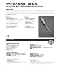
3.15 Dimensions<br />
Fig. 01: <strong>MDA</strong> 420/460<br />
with fixed stem<br />
76<br />
10
flexible<br />
76<br />
Fig. 02: <strong>MDA</strong> 422/462<br />
with flexible stem<br />
D1 D2 D3 D4 D5 A B C SW<br />
1/2"-20UNF-2A 7,8 -0,05 10,5 -0,05 11 -0,5 12,5 5,3 +0,25 11 16 16<br />
M18 x 1,5 10 -0,05 16 -0,1 16 -0,5 18 6 -0,25 14 20 19<br />
Operating manual<br />
11
Fig. 03: <strong>MDA</strong> 435/467 with capillary<br />
flexible Union nut<br />
76<br />
12
Thermocouple type J<br />
Connector + Plug connector<br />
flexible<br />
length 76<br />
flexible<br />
length 457<br />
Fig. 04: <strong>TDA</strong> 432/463 with thermocouple<br />
D1 D2 D3 D4 D5 A B C SW<br />
1/2"-20UNF-2A 7,8 -0,05 10,5 -0,05 11 -0,5 12,5 5,3 +0,25 11 16 16<br />
M18 x 1,5 10 -0,05 16 -0,1 16 -0,5 18 6 -0,25 14 20 19<br />
76<br />
Operating manual<br />
13
4. Function<br />
4.1 Construction 14<br />
4.2 Description of functions 14<br />
4.3 PT series 15<br />
4.1 Construction<br />
The PTs are industry standard.<br />
The main advantages are:<br />
- manufactured under ISO 9002<br />
- thermal stability<br />
- resistance to aggressive media<br />
- insensitivity to electromagnetic radiation (EMC)<br />
- liquid-filled transmission system (mercury)<br />
- pressure measurements in plastic melt up to a<br />
temperature of 400°C (750°F)<br />
- maximum pressure 2000 bar<br />
4.2 Description of functions<br />
Through a closed, liquid-filled pressure transmission<br />
system, the PT furnishes an electrical signal that is<br />
proportional to the pressure of the melt.<br />
The pressure applied by the medium is forwarded to the<br />
measuring diaphragm via the separating diaphragm and<br />
the mercury in the capillary. The deflection of the<br />
measuring diaphragm changes the resistance of the<br />
strain gauge bonded to the measuring diaphragm. The<br />
strain gauge is a Wheatstone bridge.<br />
An electric signal proportional to the pressure is generated<br />
via the supply voltage.<br />
14
Fig. 05:<br />
Functioning principle of the PT of the<br />
<strong>MDA</strong> 420/460 series<br />
Filling opening<br />
Strain gauge on the<br />
measuring diaphragm<br />
Capillary with pressure<br />
transmission fluid (Hg)<br />
Operating manual<br />
Total<br />
filling volume = 7 mm³<br />
Separating diaphragm<br />
0.15 mm thick<br />
4.3 PT series<br />
The <strong>MDA</strong>/<strong>LDA</strong>/<strong>TDA</strong> series PTs are also available as PT<br />
series. The PT types correspond to the <strong>MDA</strong> models,<br />
and the TPT types correspond to the <strong>TDA</strong> models; the<br />
number codes are identical. The PT series differs from<br />
the <strong>MDA</strong> series in that all specifications are given in US<br />
American units of measure.<br />
E.g.:<br />
1 bar = 14,5 PSI<br />
(PSI value is rounded)<br />
2,54 cm= 1" (inch)<br />
All other specifications are the same as in the <strong>MDA</strong><br />
series.<br />
15
5. Transport / delivery<br />
5.1 Transport / packing /<br />
transport damage 16<br />
5.2 Storage 16<br />
5.3 Scope of delivery 16<br />
Toxic hazard!<br />
The PT contains a very small amount of<br />
mercury (Hg) as its transmission medium.<br />
If the diaphragm is damaged, mercury<br />
may escape. Non-toxic NaK is being used<br />
in the <strong>LDA</strong> series. NaK is also available as<br />
an option for other pressure transducers.<br />
Never transport or store the PT without the<br />
protective shell bolted in place. Remove the<br />
shell shortly before installation.<br />
If mercury is inhaled or swallowed,<br />
seek medical attention immediately.<br />
Mercury is hazardous waste and must be<br />
disposed of in accordance with applicable<br />
laws. DYNISCO will accept defective PTs.<br />
If mercury escapes, use airtight packaging!<br />
ESD sensitive component. Electrostatic<br />
discharge may damage the PT. Take ESD<br />
precautions.<br />
5.1 Transport/packing/transport damage<br />
- Do not let the PT be damaged by other items<br />
during transit.<br />
- Use only the original packaging.<br />
- Report transport damage to DYNISCO<br />
immediately in writing.<br />
5.2 Storage<br />
- Store the PT in original packaging only.<br />
- Protect against dust and moisture.<br />
5.3 Scope of delivery<br />
- PT with diaphragm protection cap<br />
- Cable socket<br />
- Fastening clip (transducer with flexible stem only)<br />
- Calibration sheet<br />
- Operating manual<br />
16
6. Installation<br />
6.1 Mounting hole 17<br />
6.2 Checking the mounting hole 18<br />
6.3 Mounting the Pressure Transducer 19<br />
6.4 Mounting PTs with flexible stem 20<br />
6.4.1 Thermo insulation 21<br />
6.5 Electrical connection 21<br />
6.5.1 EMC / compliant connection 22<br />
6.6 Connection assignments 22<br />
6.7 Wiring 23<br />
6.8 Connection thermocouple /<br />
PT100 element 23<br />
Ambient temperature for the housing<br />
max. +120°C.<br />
Higher temperatures can result in damage<br />
and malfunctions. Mount the PT only in<br />
locations where these temperatures are not<br />
exceeded.<br />
Operating manual<br />
6.1 Mounting hole<br />
To produce the mounting hole, use only<br />
DYNISCO machining tool kit.<br />
- Drill the mounting hole as shown in figure 06/07<br />
Fig. 06: Mounting hole for transducer<br />
<strong>MDA</strong> 420, 460, 422, 462, 432, 463<br />
00014<br />
c<br />
a<br />
Thread complete<br />
b<br />
d 1<br />
d 2<br />
d 3<br />
d 4<br />
a b c<br />
1/2"-20UNF-2B 7,92 +0,05 11,5 +0,1 13 5,7 4 19<br />
M18 x 1,5 10,1 +0,05 16,3 +0,1 20 6,15 4 25<br />
17
Fig. 07:<br />
Mounting hole for transducer <strong>MDA</strong>467<br />
d 1<br />
d 2<br />
d 3<br />
1/2"-20UNF-2B 7,92 +0,05 11,5 +0,2<br />
a b c<br />
3 1,5 17<br />
When reworking the mounting hole, pay particular attention<br />
to the centricity of:<br />
- the hole,<br />
- the thread and<br />
- the sealing surface.<br />
Pressure sealing takes place on the 45° beveled sealing<br />
surface and on the front cylindrical section of the PT (see<br />
figures 06 and 07).<br />
The sealing surface must be:<br />
- correctly machined<br />
- free from marks and rough edges<br />
- free from solidified plastic residue.<br />
6.2 Checking the mounting hole<br />
- Paint the test bolt DYNISCO on the marked area<br />
(figure 08, item 1) with marking ink up to the thread.<br />
Fig. 08:<br />
test bolt with marking ink<br />
00011<br />
- Insert the test bolt in the mounting hole<br />
- Twist it in by hand until the two sealing surfaces<br />
make contact.<br />
- Remove and examine the test bolt.<br />
The only acceptable abrasion of marking ink is at the<br />
sealing edge (45°), evenly (!) over the entire circumference.<br />
If the ink has been rubbed off in other places too:<br />
- rework the mounting hole.<br />
18
6.3 Mounting the Pressure Transducer<br />
d 3<br />
0,05<br />
11,5 +0,2<br />
c<br />
17<br />
Mounting and electrical connection of the PT<br />
must be done by specialists with EMC training,<br />
following all applicable regulations, and in<br />
pressureless, voltage-free condition with<br />
the machine switched off.<br />
The machine must be secured against<br />
being switched back on!<br />
Toxic hazard!<br />
The PT contains a very small amount of<br />
mercury (Hg) as its transmission medium.<br />
If the diaphragm is damaged, mercury<br />
may escape. Non-toxic NaK is being used<br />
in the <strong>LDA</strong> series. NaK is also available as<br />
an option for other pressure transducers.<br />
Never transport or store the PT without the<br />
protective shell bolted in place. Remove the<br />
shell shortly before installation.<br />
If mercury is inhaled or swallowed, seek<br />
medical attention immediately!<br />
ESD sensitive component. Electrostatic discharge<br />
may damage the PT.Take ESD<br />
precautions.<br />
Before mounting the PT, check the mounting<br />
hole carefully. The PT must only be mounted<br />
in holes that satisfy the requirements<br />
stipulated in chapter 6.1. A hole that does not<br />
satisfy these requirements can damage the<br />
PT.<br />
Before mounting the PT, ensure that the<br />
mounting hole is free from plastic residue.<br />
Remove plastic residue with the DYNISCO<br />
cleaning tool kit. A test bolt is included with this<br />
cleaning set.<br />
To prevent the PT from sticking permanently<br />
in the mounting hole, coat the thread section<br />
of the transducer with high temperature<br />
resistant grease or a suitable parting agent.<br />
- Check the mounting hole with the test bolt, and clean<br />
with cleaning set if necessary.<br />
- Coat the thread section of the transducer with high<br />
temperature resistant grease or a suitable parting<br />
agent.<br />
Always use a spanner applied to the<br />
designated hexagon collar when screwing<br />
the PT in and out. Do not apply the tool to the<br />
housing or housing/sensor connection!<br />
Operating manual<br />
19
Maximum mounting torque 50 Nm.<br />
If the mounting torque is too high, the PT may<br />
be damaged or its zero point may shift.<br />
- screw the PT into the mounting hole and tighten.<br />
6.4 Mounting PTs with flexible stem<br />
Mounting a PT with a flexible stem to the pressure sensor<br />
is done analogously to the procedure in 6.3.<br />
Avoid kinking or crushing the flexible stem.<br />
Minimum bending radius<br />
- 25 mm for protected capillary<br />
- 2 mm for unprotected capillary<br />
(<strong>MDA</strong> 435 / 467)<br />
The connector must be easily accessible.<br />
- Mount the housing of the PT with the fastening<br />
clip DYNISCO P/N 200982 (included). See<br />
mounting example in figure 09.<br />
- Additionally secure the flexible stem between the<br />
housing with a standard cable clip.<br />
Fig. 09: Mounting example for Pressure<br />
transducer with flexible stem<br />
Housing<br />
Fastening Clip<br />
P/N 200982<br />
Fastening Clip<br />
Pressure sensor<br />
with flexible stem<br />
20
6.4.1 Thermo Insulation<br />
When installing the <strong>TDA</strong> please consider that the<br />
stem needs sufficient insulation. The insulation must<br />
cover the entire stem (see drawing). The thermo<br />
insulation is necessary for the correct temperature<br />
measurement.<br />
Fig. 10:<br />
approx. 40mm<br />
(Glass wool, etc.)<br />
Stem length<br />
Operating manual<br />
6.5 Electrical connection<br />
Mounting and electrical connection of the PT<br />
must be done by specialists with EMC training,<br />
following all applicable regulations, and in<br />
pressureless, voltage-free condition with<br />
the machine switched off.<br />
The machine must be secured against<br />
being switched back on!<br />
ESD sensitive component. Electrostatic<br />
discharge may damage the PT. Take ESD<br />
precautions.<br />
Avoid laying the power cable in the direct<br />
vicinity of cables carrying higher voltages or<br />
switching inductive or capacitive loads.<br />
An EMC compliant power supply must be<br />
used. The electrical connection must comply<br />
with EMC requirements.<br />
If the electrical connection is not made as<br />
described in chapter 6.5.1, or if cables / cable<br />
connectors / cable glands other than those<br />
stipulated by DYNISCO are used, DYNISCO<br />
cannot guarantee that EMC requirements will<br />
be satisfied.<br />
21
6.5.1 EMC / compliant connection<br />
- Earth the machine section with the screw-in trunnion<br />
/ mounting hole for the PT in accordance with<br />
regulations. The PT must be connected to earth via<br />
the screw-in trunnion / mounting hole.<br />
- Connect the shield of the connecting cable on both<br />
sides, making sure it conducts with full and continuous<br />
contact.<br />
- When introducing the connecting cable into an EMC<br />
compliant switch cabinet, for example, connect the<br />
shield correctely (cable gland, conducting, full contact,<br />
continuous) to the conductive housing or route<br />
it via built-in cable connector that is also connected<br />
to the conductive housing.<br />
- Connect unused cable cores or free cable ends<br />
correctely to the cable shield on both sides.<br />
For order numbers of EMC compliant cable connectors<br />
required for connecting the PT, see chapter 9,<br />
Accessories.<br />
6.6 Connection assignments<br />
Standard models <strong>MDA</strong> 4xx-xxx-xx:<br />
Equipment connector: 6-pin male,<br />
Bendix PT02A-10-6P<br />
Cable socket:<br />
PT06A-10-6S(SR)<br />
Fig. 11: 6-pin female connector<br />
Top view solder side<br />
PIN Designation<br />
A signal (+)<br />
B signal (-)<br />
C supply voltage (+)<br />
D supply voltage (-)<br />
E calibration<br />
F calibration<br />
The connector housing is connected conductively to<br />
the housing of the PT.<br />
22
Modelle PT 4xx (PT 420/422/435/TPT432):<br />
Equipment connector: 8-pin male,<br />
Bendix PC02E-12-8P<br />
Cable socket:<br />
PC06A-12-8S(SR)<br />
Fig. 12: 8-pin female connector<br />
Top view solder side<br />
PIN Designation<br />
A supply voltage (+)<br />
B signal (+)<br />
C supply voltage (-)<br />
D signal (-)<br />
E calibration<br />
F calibration<br />
G not used<br />
H not used<br />
The connector housing is connected conductively to<br />
the housing of the PT.<br />
Operating manual<br />
6.7 Wiring<br />
Fig. 13:<br />
Wiring proposal 6-wire strain gauge<br />
Calibration<br />
V<br />
A<br />
B<br />
C<br />
D<br />
E<br />
F<br />
<strong>MDA</strong>42x-xx-xx<br />
or<br />
<strong>MDA</strong>46x-xx-xx<br />
6.8 Connection thermocouple / PT100 element (optional)<br />
Fig. 14: Thermocouple<br />
connection<br />
Fig. 15: PT100 connection<br />
IEC<br />
584-1<br />
3 4<br />
1 2<br />
1<br />
2<br />
υ<br />
3<br />
4<br />
2-wire<br />
3-wire<br />
4-wire<br />
23
7. Commissioning<br />
7.1 Supply voltage 24<br />
7.2 Calibration 24<br />
7.3 Zero adjustment 25<br />
7.4 Operation 25<br />
Before putting the PT into operation, make<br />
sure the PT is securely mounted and sealed.<br />
7.1 Supply voltage<br />
DYNISCO recommends operating the pressure<br />
transducer with a supply voltage of 10 VDC. Supply<br />
voltages from 6 to 12 VDC are permitted.<br />
Using a supply voltage which is different from<br />
that stated in the technical specifications or<br />
has reversed polarity can damage the PT or<br />
cause it to malfunction.<br />
7.2 Calibration<br />
PTs of series <strong>MDA</strong> 420/460 have an internal calibration<br />
signal. Connecting terminals E and F switches the<br />
calibration signal to the signal output. It is 80% of the full<br />
scale pressure of the transducer.<br />
Calibrate in pressureless state and at room<br />
temperature. Other ambient temperatures<br />
will corrupt the signal.<br />
Do not change the installed position of the PT<br />
after calibration. If the position is changed you<br />
must re-calibrate the PT.<br />
- Connect a meter or suitable display unit to the signal<br />
output.<br />
- Set the display unit or external amplifier to<br />
pressureless state (zero point).<br />
- Connect terminals E and F.<br />
➪ The calibration signal is connected to the<br />
output.<br />
- Set the calibration value (80% of nominal pressure)<br />
on the display unit or external amplifier.<br />
- Check the zero point setting on the display unit once<br />
again.<br />
24
7.3 Zero adjustment<br />
For PTs of this series, adjust zero at operating<br />
temperature!<br />
- Wait until a steady operating temperature is reached<br />
at the pressure sensor.<br />
- Set the zero point on the display unit or external<br />
amplifier.<br />
7.4 Operation<br />
Before starting the machine, wait until the melt<br />
medium at the diaphragm of the PT has<br />
reached its operating/processing temperature.<br />
If the machine is started before the<br />
medium reaches its operating temperature,<br />
the PT will be damaged. If it is hard to tell when<br />
the operating temperature has been reached,<br />
use a combined <strong>TDA</strong> PT with thermocouple.<br />
Operating manual<br />
Operating temperature at the PT diaphragm<br />
max. 400°C (750°F). Higher temperatures<br />
will damage the PT.<br />
Ambient temperature for the housing<br />
max. +120°C. Higher temperatures can result<br />
in damage or malfunctions.<br />
Mount the PT only in locations where this<br />
temperature is not exceeded.<br />
25
8. Maintenance<br />
8.1 Maintenance 26<br />
8.2 Thermocouple replacement <strong>TDA</strong> models 27<br />
8.3 Repair/disposal 28<br />
8.1 Maintenance<br />
Mounting and electrical connection of the PT<br />
must be done by specialists with EMC training,<br />
following all applicable regulations, and in<br />
pressureless, voltage-free condition with<br />
the machine switched off.<br />
The machine must be secured against<br />
being switched back on!<br />
Burn hazard!<br />
The PT must be removed with the melt in<br />
molten condition. The PT can be very hot<br />
when removed.<br />
Wear protective gloves!<br />
ESD sensitive component. Electrostatic<br />
discharge may damage the PT. Take ESD<br />
precautions.<br />
Always remove the PT before cleaning the<br />
machine with abrasives ro steel wire brushes<br />
or suchlike.<br />
Before removing the PT, the medium must be<br />
in molten condition.<br />
Removing the transducer with the medium in<br />
solidified condition can damage the diaphragm<br />
of the PT.<br />
Do not clean the screw-in section of the PT<br />
with hard objects. This will damage the PT!<br />
Always use a spanner applied to the<br />
designated hexagon collar when screwing<br />
the PT in and out. Do not apply the tool to the<br />
housing or housing/sensor connection!<br />
- Remove the PT.<br />
- Carefully clean the diaphragm of the transducer with<br />
a soft cloth, while the medium is still malleable.<br />
26
8.2 Thermocouple replacement <strong>TDA</strong> models<br />
A defective thermocouple is easy to replace.<br />
- Loosen the hexagon socket screw at the top end of<br />
the sensor stem.<br />
- Remove the defective thermocouple from the probe<br />
stem.<br />
When fitting the new thermocouple, the<br />
pressure transmitting capillary must be<br />
located in the slot of the thermocouple.<br />
- Insert the new thermocouple all the way into the<br />
probe stem.<br />
- Tighten the hexagon socket screw at the top of the<br />
sensor stem to secure the thermocouple.<br />
Fig. 16: Thermocouple<br />
Operating manual<br />
Thermocouple<br />
Fixing<br />
screw<br />
Pressure transmitting<br />
capillary<br />
Pressure<br />
transmission<br />
27
8.3 Repair/disposal<br />
Toxic hazard!<br />
The transmission medium in the PT is<br />
mercury (Hg). If the diaphragm is<br />
damaged, mercury may escape.<br />
Never transport or store the PT without the<br />
protective shell bolted in place. Remove the<br />
shell shortly before installation.<br />
If mercury is inhaled or swallowed, seek<br />
medical attention immediately!<br />
Mercury is hazardous waste and must be<br />
disposed of in accordance with applicable<br />
laws. DYNISCO will accept defective PTs.<br />
If mercury escapes, use airtight packaging!<br />
Please send defective PTs to your DYNISCO representative.<br />
For addresses, see the back cover of the operating<br />
manual.<br />
9. Accessories<br />
- Machining tool kit ½"-20UNF-2A P/N 8BRD0004<br />
- Machining tool kit M18 x 1,5 P/N 8BRD0005<br />
- Cleaning tool kit ½"-20UNF-2A P/N 8BRD0009<br />
- Cleaning tool kit M18 x 1,5 P/N 8BRD0006<br />
- Pressure sensor simulator<br />
- Pressure sensor calibrating device<br />
Connectors, Cable glands, Cable<br />
Designation<br />
Order No.<br />
Female connector DIN 7-pin E311 0035<br />
Female connector Bendix E311 0029<br />
Cable gland PG 7 CE E447 0037<br />
Connecting cable VT 460 - 6 meter 9VT0 0017<br />
Connecting cable VT 460 - 10 meter 9VT0 0018<br />
28
10. Troubleshooting<br />
10.1 Troubleshooting 29<br />
10.1 Troubleshooting<br />
Fault<br />
No signal<br />
Possible cause<br />
Cable breakage or<br />
poor contact<br />
No supply voltage<br />
Resolution<br />
Check cable<br />
and contact, or<br />
replace<br />
Check supply<br />
voltage<br />
Operating manual<br />
Strong zero shift<br />
when screwing in<br />
Mounting hole<br />
incorrectly<br />
produced<br />
(alignment error)<br />
Check hole with<br />
test bolt<br />
(chapter 6.2),<br />
rework with tool<br />
if necessary<br />
Mounting torque<br />
too high<br />
Adjust to max.<br />
50 Nm mounting<br />
torque<br />
No signal change<br />
despite pressure rise<br />
Plug forming in<br />
front of diaphragm<br />
Check mounting<br />
hole; remove<br />
solidified plastic<br />
Diaphragm<br />
damaged<br />
Send pressure<br />
transducer to<br />
DYNISCO for<br />
repair<br />
29
11. Declaration of conformity<br />
Konformitätserklärung<br />
Declaration of conformity<br />
Déclaration de conformité<br />
Declaración de conformidad<br />
Declaração de conformidade<br />
Dichiarazione di conformità<br />
Verklaring van overeenstemming<br />
Konformitetserklæring<br />
Ah/lwsh summo/rfwshs EOK<br />
Hiermit erklären wir, daß unser Produkt, Typ:<br />
We hereby declare that our product, type:<br />
Nous déclarons par la présente que notre produit, type:<br />
Por la presente declaramos que nuestro producto, tipo:<br />
Com a presente, declaramos que o nosso produto, tipo:<br />
Con la presente dichiariamo che il nostro prodotto tipo:<br />
Hiermee verklaren wij dat ons produkt, type:<br />
Hermed erklærer vi, at vores produkt af typen:<br />
Me thn parou/sa dhlw/noume, o/ti to proio/n<br />
mas tu/pou :<br />
folgenden einschlägigen Bestimmungen entspricht:<br />
complies with the following relevant provisions:<br />
correspond aux dispositions pertinentes suivantes:<br />
satisface las disposiciones pertinentes siguientes:<br />
está em conformidade com as disposições pertinentes,<br />
a saber:<br />
è conforme alle seguenti disposizioni pertinenti:<br />
voldoet aan de eisen van de in het vervolg genoemde<br />
bepalingen:<br />
overholder følgende relevante bestemmelser:<br />
antapokri/netai stous ako/louqous<br />
sxetikou/s kanonismou/s:<br />
Drucktransmitter / Druckaufnehmer<br />
Pressure Transmitter / Pressure Transducer<br />
Serie MDT, EMT, EIT, <strong>MDA</strong>, IDA, <strong>TDA</strong>, <strong>LDA</strong>,<br />
PT, Dyna4<br />
EMV-Richtline (89/336/EWG, 93/68/EWG, 93/44 EWG)<br />
EMC guidelines (89/336/EEC, 93/68/EEC, 93/44/EEC)<br />
Direcitve EMV (89/336/CEE, 93/68/CEE, 93/44/CEE)<br />
Reglamento de compatibilidad electromagnética<br />
(89/336/MCE, 93/68/MCE, 93/44/MCE)<br />
Directriz relativa à compatibilidade electro-magnética<br />
(89/336/EWG, 93/68/EWG, 93/44/EWG)<br />
Direttiva sulla compatibilità elettromagnetica<br />
(89/336/CEE, 93/68/CEE, 93/44/CEE)<br />
EMV-richtlijn (89/336/EEG, 93/68/EEG, 93/44/EEG)<br />
Direktiv om elektromagnetisk forligelighed<br />
(89/336/EØF, 93/68/EØF, 93/44/EØF)<br />
kateuqunth/ria odhgia peri<br />
hlektromagnhtikh/s sumbato/thtas<br />
(89/336/EWG, 93/68/EWG, kai 93/44/EWG)<br />
Angewendete harmonisierte Normen,insbesondere:<br />
Applied harmonized standards, in particular:<br />
Normes harmonisée utilisées, notamment:<br />
Normas armonizadas utilzadas particularmente:<br />
Normas harmonizadas utilizadas, em particular:<br />
Norme armonizzate applicate in particolare:<br />
Gebruikte geharmoniseerde normen, in het bijzondere:<br />
Anvendte harmoniserede normer, især:<br />
Efarmosqe/nta enarmonisme/na pro/tupa,<br />
eidiko/tera:<br />
EN 50081-1 / EN 50082-2<br />
<strong>Dynisco</strong> Europe GmbH<br />
Wannenäckerstraße 24<br />
D 74078 Heilbronn<br />
Tel. (0 71 31) 2 97 - 0<br />
Fax (0 71 31) 2 32 60<br />
Heilbronn, den 1. Mai 1996<br />
Daniel Nigg, Geschäftsführer<br />
30
Visit us<br />
in the world wide web:<br />
<strong>Dynisco</strong> <strong>Instruments</strong><br />
38 Forge Parkway<br />
Franklin, MA 02038<br />
USA<br />
Tel: +1 508 541 9400<br />
Fax: +1 508 541 9437<br />
Email: InfoInst@dynisco.com<br />
<strong>Dynisco</strong> Europe GmbH<br />
Wannenäckerstraße 24<br />
74078 Heilbronn<br />
Deutschland<br />
Tel: +49 7131 2970<br />
Fax:+49 7131 23260<br />
Email: <strong>Dynisco</strong>Europe@dynisco.com<br />
<strong>Dynisco</strong> <strong>Instruments</strong> S.a.r.l.<br />
466, rue du Marché Rollay<br />
94500 Champigny sur Marne<br />
France<br />
Tel: +33 1 4881 8459<br />
Fax: +33 1 4881 8334<br />
Email. <strong>Dynisco</strong>France@dynisco.com<br />
<strong>Dynisco</strong>.s.r.l.<br />
Via Adriatico, 2/2<br />
20162 Milano<br />
Italia<br />
Tel: +39 02 661 01733<br />
Fax: +39 02 661 02908<br />
Email: <strong>Dynisco</strong>Italy@dynisco.com<br />
<strong>Dynisco</strong> UK Ltd.<br />
Silver Birches Business Park<br />
Aston Road, Bromsgrove<br />
Worcestershire B60 3EU<br />
Great Britain<br />
Tel: +44 1527 577077<br />
Fax: +44 1527 577070<br />
Email: <strong>Dynisco</strong>UK@dynisco.com<br />
<strong>Dynisco</strong> SPOL, S.R.O.<br />
cp. 579<br />
756 55 Dolni Becva<br />
Czech Republic<br />
Tel: +42 0571 647228<br />
Fax: +42 0571 647224<br />
Email: <strong>Dynisco</strong>cz@nextra.cz<br />
<strong>Dynisco</strong> B.V.<br />
Muziekplein 67<br />
PO Box 666<br />
NL-5400 AR Uden<br />
The Netherlands<br />
Tel: +31 413 250665<br />
Fax: +31 413 260548<br />
Email: <strong>Dynisco</strong>-BV@dynisco.com<br />
www.dynisco.com<br />
Operating manual<br />
Technische Änderungen vorbehalten 9LIT0220 05/03<br />
Technical subject to change<br />
Sous réserve de modifications techniques<br />
Con riserva di modifiche tecniche 31