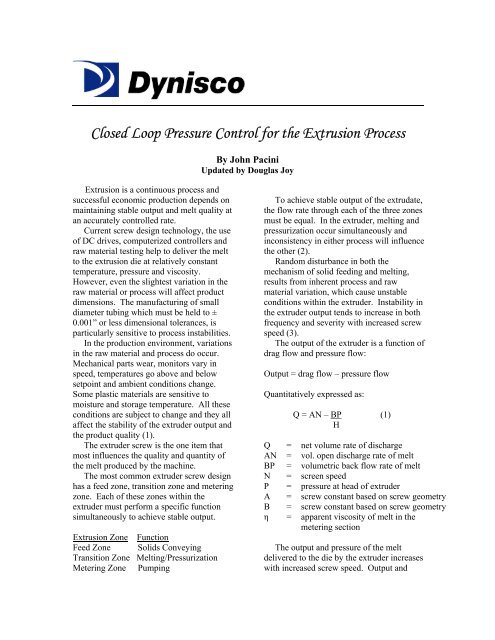
Closed Loop Pressure Control for the Extrusion Process
Closed Loop Pressure Control for the Extrusion Process
Closed Loop Pressure Control for the Extrusion Process

You also want an ePaper? Increase the reach of your titles
YUMPU automatically turns print PDFs into web optimized ePapers that Google loves.
downstream equipment, no downstreamchanges will be required.Test MethodTest results are presented in Table 2 andplotted on graphs shown in Figures 3 through6, which demonstrate <strong>the</strong> effectiveness ofclosed loop feedback pressure control inminimizing output variations.Tests were made on a 2½” extruderprocessing 100% LDPE regrind at screwspeeds of 35, 50, 70 and 100 rpm. Use of100% LDPE regrind simulates <strong>the</strong> worstsurging conditions. The tests were madeutilizing a melt pressure transducer mountedin <strong>the</strong> die and a microprocessor-basedpressure controller. The PID output of <strong>the</strong>controller was fed to <strong>the</strong> extruder drive. TheTABLE 2. Test Resultsoutput of <strong>the</strong> controller was used tocontinually adjust <strong>the</strong> screw speed in order tomaintain a constant die pressure.• Graphs with broken linesindicate product linear weightover time with no pressurecontrol (fixed screw speed).• Graphs with solid lines indicateproduct linear weight over timewith control of die pressure(continually adjusted screwspeed).Extruder Speed withand without <strong>Pressure</strong><strong>Control</strong>35 RPM Nominalw/o pressure controlw/ pressure control% reduction50 RPM Nominalw/o pressure controlw/ pressure control% reduction75 RPM Nominalw/o pressure controlw/ pressure control% reduction100 RPM Nominalw/o pressure controlw/ pressure control% reductionPolymer <strong>Pressure</strong>at DieAvg Variation %Variation(B)16851870162516951775203026502850859027515544519016070114.856%179.146.4%25.19.462.5%6.02.558%Product Linear WeightAvg Variation %Variation(A)1.0751.141.92.091.9052.5752.533.220.3250.08750.50.290.8050.3750.320.132307.7774%26.313.947%40.614.664%12.64.266.7%Change in Productweight (A)Change in <strong>Pressure</strong>(B)2.701.621.551.531.621.552.101.68ResultsLinear weight output variation was 153%to 270% (1.53 to 2.70 times) of <strong>the</strong> pressurevariation. Based on <strong>the</strong> pressure variations,which occurred during <strong>the</strong> tests, outputvariations were not as large as <strong>the</strong>oreticallypredicted in Table 1. However, in all caseslinear weight output variation was greaterthan <strong>the</strong> pressure variation.
fluctuation, reducing <strong>the</strong> average inlet meltpressure, and increasing <strong>the</strong> safety ofoperation (2).The reduction in product linear weightoutput variation ranged from 47% to 74%(see Column A, Table 2). This suggests thatas a minimum, variations in output can becut in half using closed loop pressurecontrol.<strong>Closed</strong> <strong>Loop</strong> <strong>Pressure</strong> <strong>Control</strong> <strong>for</strong> MeltPump <strong>Extrusion</strong>Melt pump assisted extrusion is gainingpopularity as a method of stabilizing <strong>the</strong>extrusion process. The literature states that agear pump helps to eliminate unexpectedsurges and drifting output rates from <strong>the</strong>extruder (2) (6-9).Gear pumps are positive displacementdevices that deliver polymer melt to <strong>the</strong>extruder die at a relatively constant rate. INgear pump extrusion, <strong>the</strong> primary function of<strong>the</strong> extruder is to act as a plasticating unit todeliver a homogenous melt to <strong>the</strong> gear pumpinlet.The gear pump which is mountedbetween <strong>the</strong> extruder and <strong>the</strong> die, buffers <strong>the</strong>die from extruder surges and drifts in output,but <strong>the</strong> inlet of <strong>the</strong> gear pump itself is subjectto <strong>the</strong>se extruder output variations. Since <strong>the</strong>pump requires a constant flow of plasticwithin certain pressure levels <strong>for</strong> lubrication,a prolonged low-pressure condition couldcause damage to <strong>the</strong> pump. Overpressurization at <strong>the</strong> pump inlet, caused by asudden surge of melt from <strong>the</strong> extruder, willchange <strong>the</strong> melt condition and in extremecases, can be dangerous to <strong>the</strong> equipmentand operatorFor <strong>the</strong>se and o<strong>the</strong>r reasons, a closed looppump inlet pressure control system thatchanges <strong>the</strong> extruder screw speed to maintaina constant gear pump inlet pressure offers anumber of processing advantages.A study conducted by Dynisco and <strong>the</strong>University of Lowell concluded that controlsystem of this type simplifies and improvesprocess operations by completely eliminatinglong term inlet pressure drift, significantlyreducing short term inlet pressureThe following is a brief summary of <strong>the</strong>results:Short Term Inlet <strong>Pressure</strong> StabilityLarge fluctuations in <strong>the</strong> inlet pressuredictate that a higher average inlet pressureshould be used to avoid dropping below <strong>the</strong>minimum inlet pressure. Even a temporaryloss of inlet pressure will show on <strong>the</strong>discharge side of <strong>the</strong> pump. The higheraverage pump inlet pressure increases <strong>the</strong>energy input to <strong>the</strong> material, increasing <strong>the</strong>average melt temperature. Figure 7 showspump inlet and discharge pressures <strong>for</strong> bothmanual and closed loop operation at a pumpinlet pressure setpoint of 350 psi. Figure 8shows that short term inlet pressurevariations were reduced 70-80%.Long Term <strong>Pressure</strong> DriftWith manual control, it was necessary toperiodically adjust screw speed, producing<strong>the</strong> result shown in Figure 9. With closedloop pressure control (Figure 10) some shortterminlet pressure instability was observedbut long-term pressure drift was completelyeliminated.<strong>Process</strong> Output ChangeA smooth, well-coordinated change inoutput rate was difficult to achieve withmanual control. An increase in pump speedrequired simultaneous and coordinatedincreases in extruder speed, often resulting inexcessive pressurization at <strong>the</strong> pump inlet.<strong>Closed</strong> lop inlet pressure control simplified<strong>the</strong> operation considerably. An increase ordecrease in <strong>the</strong> pump speed was
automatically followed by <strong>the</strong> extruder(Figure 11).Safety<strong>Closed</strong> loop inlet pressure controlincreases operator and equipment safety. If,during manual operation, <strong>the</strong> pump ceasesrotation and <strong>the</strong> extruder continues to pumppolymer, pressure at <strong>the</strong> pump inlet reachesdangerous levels in a matter of seconds.Mechanical rupture plugs, electricalinterlocks or high inlet pressure limit relays(a feature of some controllers) should beused.SUMMARYAlthough modern extruder drives andtake-off devices provide constant, drift-freeoperation, variations in <strong>the</strong> raw material andprocess occur which causes <strong>the</strong> output of <strong>the</strong>extruder to change. The output instability of<strong>the</strong> extruder is related to <strong>the</strong> melt pressure at<strong>the</strong> die. The output variations of <strong>the</strong>extrudate will be a multiple of <strong>the</strong> pressurevariation at <strong>the</strong> die. A closed loop feedbacksystem, which adjusts screw speed tomaintain a constant die pressure, is <strong>the</strong> mosteffective method to minimize variations inextruder output.<strong>Closed</strong> loop inlet pressure control <strong>for</strong> gearpump extrusion reduces inlet pressureinstability, as well as <strong>the</strong> average minimuminlet pressure. Reducing <strong>the</strong> inlet pressurevariations assures a more uni<strong>for</strong>m melttemperature at <strong>the</strong> die, thus improving <strong>the</strong>consistency and quality of <strong>the</strong> extrudate.
Figure 1. Output and <strong>Pressure</strong> Relationship of <strong>the</strong> Extruder DieFigure 2. Effect of Changes in Extruder Output on Die <strong>Pressure</strong>
Figure 3.Figure 4.
Figure 5.Figure 6.
Figure 7. Short Term Inlet <strong>Pressure</strong> Stability @ Pump Speed: 35 RPM (Approximately 105 RPMExtruder Screw Speed): Manual and <strong>Closed</strong> <strong>Loop</strong> Operation.Figure 8. Short Term Pump Inlet <strong>Pressure</strong> Stability vs. Pump Speed: Manual and <strong>Closed</strong> <strong>Loop</strong>Operation.
Figure 9. Long Term Pump Inlet <strong>Pressure</strong> Drift: Manual Adjustment in Extruder Screw Speed.Figure 10. Long Term Inlet <strong>Pressure</strong> Drift with <strong>Closed</strong> <strong>Loop</strong> Inlet <strong>Pressure</strong> <strong>Control</strong>.
Figure 11. <strong>Closed</strong> <strong>Loop</strong> Pump Inlet <strong>Pressure</strong> Response to a Pump Speed Change.REFERENCES1. Dynisco, Inc. “An Economical Method of Stabilizing <strong>the</strong> <strong>Extrusion</strong> <strong>Process</strong>”.2. Malloy, Robert A., SPEC ANTEC, p. 604, (1984).3. Steven, M. J., “Extruder Principle and Operation”, Elsevier Applied Science Publishers,pp. 101, 211, 237-248, (1985).4. I. Patterson, T. DeKerf, SPE ANTEC, p. 483, (1978).5. Frados, J. “Plastics Engineering Handbook, SPI, Fourth Edition”, pp. 156-174, (1976).6. Fox, Steve A., <strong>Extrusion</strong> Technology <strong>for</strong> Tubing and Profiles Seminar, Killion Extruders,Inc. (1988).7. Kruder, George, PM&E, p. 24, Vol. 18, No. 5, (May 1989).8. Kramer, William A., SPE ANTEC, p. 23 (1985).9. Rice, William T., “The Case <strong>for</strong> Gear Pumps: What’s Behind <strong>the</strong> New Interest”, PlasticsTechnology, pp. 87-91, February 1980.10. Maddock, B. H., “Measurements and Analysis of Extruder Stability”, Union CarbideTechnical In<strong>for</strong>mation.11. Plastics World “Extruders Gear Up <strong>for</strong> Tighter Gauge Limits”, pp. 42-45, July 1985.