INFILTRATION DEVICES - HCCREMS
INFILTRATION DEVICES - HCCREMS
INFILTRATION DEVICES - HCCREMS

Create successful ePaper yourself
Turn your PDF publications into a flip-book with our unique Google optimized e-Paper software.
WATER SMART Practice Note 5<br />
<strong>INFILTRATION</strong> <strong>DEVICES</strong><br />
<strong>INFILTRATION</strong> <strong>DEVICES</strong><br />
In this practice note:<br />
• Infiltration system overview<br />
• Infiltration retention systems<br />
• Infiltration materials & devices<br />
• Design issues<br />
• Costs<br />
WaterSmart development involves simple<br />
design and management practices that<br />
take advantage of natural site features<br />
and minimise impacts on the water cycle.<br />
It is part of the contemporary trend towards<br />
more ‘sustainable’ solutions that<br />
protect the environment and cost less.<br />
This WaterSmart Practice Note explains<br />
how to design and configure stormwater<br />
infiltration devices.<br />
PRACTICE<br />
NOTE<br />
5<br />
I n t r o d u c t i o n<br />
This Practice Note describes how to design<br />
and construct various types of<br />
stormwater infiltration devices for dwellings<br />
and other similar-scale development.<br />
There is growing interest in infiltration<br />
as an alternative or supplement to<br />
conventional drainage techniques due to<br />
its many environmental and economic<br />
benefits. These benefits include reduced<br />
peak stormwater flows, reduced downstream<br />
flooding, reduced stormwater<br />
drainage capital costs, improved groundwater<br />
recharge and improved stormwater<br />
quality.<br />
Conventional stormwater practice typically<br />
involves discharging stormwater<br />
from residential properties to a constructed<br />
street drainage system. Such<br />
systems are highly effective for removing<br />
stormwater from the site, but can also<br />
contribute to flooding risk, erosion and<br />
sedimentation and water quality decline<br />
in downstream catchments. Prior to the<br />
construction of urban drainage systems<br />
in the late 19th Century, one of the most<br />
common methods for managing stormwater<br />
was on-site gravel infiltration pits.<br />
These provided temporary storage, and<br />
allowed stormwater to percolate to the<br />
surrounding soil at a rate limited by the<br />
soil’s hydraulic conductivity.<br />
Modern infiltration devices are much<br />
more efficient than their traditional counterparts.<br />
They are constructed so as to<br />
minimise clogging by silt material, and<br />
can be designed to overflow to landscaped<br />
areas or the street drainage system<br />
when their storage capacity is exceeded<br />
during major storms. A number<br />
of pollutant removal mechanisms operate<br />
within infiltration devices, including adsorption,<br />
straining, microbial decomposition<br />
in the gravel layer and trapping of<br />
sediment in the pre-treatment areas. If<br />
correctly designed, an infiltration device<br />
can remove approximately 90% of sediment,<br />
60% of phosphorus and 60% of<br />
nitrogen from stormwater.<br />
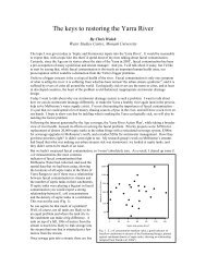
This Practice Note draws upon the latest<br />
design and performance results for Australian<br />
conditions. Research undertaken<br />
at the University of Newcastle (Coombes<br />
et al 1999, Coombes 2002) and the University<br />
of South Australia (Allen and Argue<br />
1992, Argue et al 1998, Argue 2002)<br />
shows that infiltration is a very practical<br />
option for managing stormwater provided<br />
that site conditions such as slope, soil<br />
permeability and reactivity to water are<br />
correctly taken into account.<br />
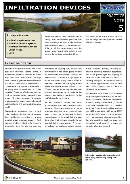
Infiltration basin under normal conditions<br />
(left), and during heavy rain<br />
(above).<br />
© <strong>HCCREMS</strong> 2007 WaterSmart Practice Note No 5 1
WATER SMART Practice Note 5<br />
<strong>INFILTRATION</strong> <strong>DEVICES</strong><br />
S Y S T E M O V E R V I E W<br />
Infiltration devices can be used as a sole<br />
approach or in unison with rainwater<br />
tanks, porous paving and landscape<br />
measures (see Practice Notes 4, 6 and 7<br />
respectively) to manage stormwater. An<br />
infiltration device collects the rain that<br />
falls on site, stores it temporarily and<br />
then releases it slowly into the ground.<br />
There are three parts of an infiltration<br />
device:<br />
1. Site drainage system<br />
The site drainage system e.g. roof gutters,<br />
downpipes, paths and driveways<br />
which collect and deliver stormwater to<br />
the infiltration device.<br />
Table 1: Types of pollutants and mechanisms to protect infiltration devices<br />
Type of<br />
pollutants<br />
System<br />
Protection<br />
Roof water<br />
Environment<br />
Protection<br />
System<br />
Protection<br />
Stormwater<br />
Environment<br />
Protection<br />
Gross <br />
Particulate<br />
matter <br />
Soluble<br />
As required<br />
Protection<br />
mechanisms<br />
- Leaf guards<br />
- First flush device<br />
- Leaf screen<br />
- Sediment trap<br />
- Contour banks<br />
- Vegetation<br />
- Grass swales<br />
- Biofiltration<br />
strips<br />
- Wetlands<br />
2. Pre-treatment system<br />
The pre-treatment system receives water<br />
runoff prior to entering an infiltration device<br />
to remove gross pollutants, particular<br />
matter and soluble pollutants. Pretreatment<br />
protects and maximises the life<br />
of the infiltration device and improves the<br />
quality of water entering the environment.<br />
Table 1, outlines the types of pollutants<br />
found in different water sources<br />
and mechanisms used to protect the<br />
infiltration device and/or improve water<br />
quality.<br />
3. Infiltration retention<br />
system<br />
The retention system stores roof water and<br />
stormwater until it can percolate into the<br />
surrounding soil (Fig 1). There are a number<br />
of options for using stormwater infiltration<br />
on residential properties. The most<br />
commonly used systems are:<br />
• leaky wells<br />
• retention trenches<br />
• infiltration basins.<br />
Fig 1: A typical infiltration strategy<br />
T Y P E S O F S Y S T E M S<br />
1. Leaky wells<br />
A leaky well consists of a vertical perforated<br />
pipe with a lid at the ground surface<br />
and an open bottom. Stormwater enters<br />
via an inlet pipe at the top and an overflow<br />
pipe caters for excess stormwater.<br />
The holes in the walls and the open bottom<br />
are covered with geotextile fabric to<br />
cleanse stormwater as it percolates into<br />
the surrounding soil (see Figure 2).<br />
Leaky wells store stormwater until it can<br />
percolate to the surrounding soil. Before<br />
entering the device, all stormwater should<br />
be filtered by a sediment trap to remove<br />
sediment, leaves and debris. An advantage<br />
of the leaky well is that the accessible<br />
chamber allows sediment to be readily removed.<br />
Consequently it is more resistant to<br />
failure due to clogging. Note that the dimensions<br />
shown in Figure 2 are nominal.<br />
© <strong>HCCREMS</strong> 2007 WaterSmart Practice Note No 5 2
WATER SMART Practice Note 5<br />
<strong>INFILTRATION</strong> <strong>DEVICES</strong><br />
Fig 2: The leaky well infiltration system<br />
2. Retention trenches<br />
A retention trench consists of a trench<br />
lined with geotextile fabric and filled with<br />
coarse gravel, and placed under a 300<br />
mm layer of sand or loam. Stormwater is<br />
conveyed to the trench via an inflow pipe<br />
after passing through a sediment trap. A<br />
perforated distribution pipe allows stormwater<br />
to percolate to the gravel. An overflow<br />
pipe directs excess flow during very<br />
heavy rain to the street drainage system<br />
(see Figure 3).<br />
The sediment trap prevents clogging of<br />
the trench with sediment, leaves and<br />
debris, whilst the geotextile fabric<br />
cleanses the stormwater as it percolates<br />
from the trench to the surrounding soil.<br />
The detailed design for a retention trench<br />
can vary provided it includes the basic<br />
elements referred to above. Note that<br />
the dimensions shown in Figure 3 are<br />
nominal.<br />
Fig 3: Design for a retention trench<br />
3. Infiltration basins<br />
An infiltration basin collects and stores<br />
stormwater runoff until it infiltrates to the<br />
surrounding soil and evaporates to the<br />
atmosphere. By removing a portion of<br />
stormwater runoff, infiltration basins reduce<br />
stormwater peak discharges and<br />
volumes to downstream catchments.<br />
They also improve the quality of stormwater<br />
discharged to the receiving environment.<br />
An infiltration basin is designed as a depression<br />
with good grass coverage over<br />
a layer of coarse gravel surrounded by<br />
geotextile fabric. A 300 mm layer of topsoil<br />
is usually placed between the gravel<br />
layer and the grassed surface. Stormwater<br />
entering the basin is filtered to remove<br />
sediment, leaves and debris by<br />
sediment traps, vegetated areas or specially<br />
designed gutter systems. Stormwater<br />
fills the basin and the gravel layer,<br />
percolates to the soil and overflows to<br />
the street drainage system when the<br />
basin fills.<br />
A schematic diagram for an infiltration<br />
basin is shown in Figure 4. Infiltration<br />
basins are more suitable for larger lots<br />
where there is plenty of space. Their<br />
design should be well-integrated with<br />
landscape measures (see Practice Note<br />
No. 7).<br />
© <strong>HCCREMS</strong> 2007 WaterSmart Practice Note No 5 3
WATER SMART Practice Note 5<br />
<strong>INFILTRATION</strong> <strong>DEVICES</strong><br />
Fig 4: Design for an infiltration basin<br />
T Y P E S O F M A T E R I A L S & D E V I C E S<br />
1. Void Materials<br />
Void materials such as gravel, crushed<br />
concrete, sand, infiltration cells (similar to<br />
a plastic milk crate), tyres filled with<br />
gravel and enviromedia (a mix of sand/<br />
gravel and organic material) fill infiltration<br />
devices. Void materials contain spaces<br />
that store and filter water before it percolates<br />
into the surrounding soil. Sand,<br />
gravel, crushed concrete, infiltration cells<br />
and tyres, are inert media capable of<br />
removing particulate-bound matter<br />
largely through physical filtration. Enviromedia<br />
is a reactive media that removes<br />
both particulate-bound and soluble material.<br />
The table below provides a general<br />
indication of the performance (most to<br />
least) of each material relative to its water<br />
storage capacity, weight bearing capacity,<br />
pollutant removal ability, and typical<br />
proportion of recycled materials.<br />
Void space<br />
Weight<br />
support<br />
Pollutant<br />
removal ability<br />
Recycled<br />
material<br />
Most<br />
Infiltration<br />
cells<br />
Gravel/<br />
Crushed concrete<br />
Enviromedia<br />
Tyres/<br />
Crushed concrete<br />
Tyres Sand Sand<br />
Infiltration cells/<br />
Enviromedia<br />
Gravel/<br />
Crushed concrete<br />
Enviromedia<br />
Gravel/<br />
Crushed concrete<br />
Gravel<br />
Enviromedia<br />
Tyres<br />
Tyres/<br />
Infiltration cells<br />
Sand<br />
Least<br />
Sand<br />
Infiltration<br />
cells<br />
2. Geotextile fabric<br />
Geotextile is a synthetic engineered fabric<br />
used in in-line infiltration devices to<br />
cleanse water percolating into the soil<br />
and to prevent erosion during construction.<br />
3. Seepage or agricultural<br />
pipes<br />
A seepage pipe is a pipe with pervious<br />
walls, formed by punched or moulded<br />
holes, that allows stormwater to percolate<br />
into the surrounding soil. Seepage<br />
pipes are installed in a similar fashion to<br />
retention trenches.<br />
The pipe is surrounded<br />
by sand or gravel in a trench<br />
and covered with sand or loam to a thickness<br />
of 300 mm (see Figure 5).<br />
Fig 5: Seepage pipe installation<br />
© <strong>HCCREMS</strong> 2007 WaterSmart Practice Note No 5 4
WATER SMART Practice Note 5<br />
<strong>INFILTRATION</strong> <strong>DEVICES</strong><br />
D E S I G N I S S U E S<br />
1. Clearance from buildings<br />
Soils can shrink or swell depending<br />
on their clay and water content,<br />
presenting potential problems<br />
for building foundations.<br />
However, research shows that<br />
only minimum soil movement is<br />
associated with the intermittent<br />
release of stormwater from infiltration<br />
devices. The possibility of<br />
Soil type<br />
Hydraulic Conductivity<br />
an infiltration device impacting on<br />
the structural integrity of a building<br />
can be eliminated by observing<br />
minimum clearances.<br />
The recommended minimum<br />
separation between an infiltration<br />
device and a building for various<br />
soil types is shown in the following<br />
table. Check with your local<br />
council for any local requirements<br />
that they may have.<br />
Minimum Building<br />
Clearance<br />
Sand >180 mm/hr 1 m<br />
Sandy clay 180 – 36 mm/hr 2 m<br />
Medium clay 36 – 3.6 mm/hr 4 m<br />
Reactive clay 3.6 – 0.036 mm/hr 5 m<br />
2. Unsuitable soils<br />
Infiltration devices should not be<br />
installed in:<br />
• saline, sodic or very shallow<br />
soils<br />
• wind blown or loose sands<br />
• clay soils that collapse in contact<br />
with water or have high<br />
shrink/swell characteristics<br />
• soils with a hydraulic conductivity<br />
of less than 0.36 mm/hr.<br />
Soil assessment and permeability<br />
testing must be undertaken as<br />
part of the design process for infiltration<br />
devices.<br />
3. Slope<br />
Infiltration devices should not be<br />
installed on steep slopes. Installation<br />
of infiltration devices on<br />
slopes greater than 5% is not recommended<br />
unless a detailed engineering<br />
analysis is undertaken<br />
at the design stage.<br />
4. Rock & shale<br />
Infiltration devices should not be<br />
placed in rock that has little or no<br />
permeability. Studies have shown<br />
that infiltration is possible in severely<br />
weathered or fractured rock<br />
(for example, sandstone). Engineering<br />
testing is essential in<br />
these circumstances to ensure<br />
that the rock will accept infiltration.<br />
In the case of shallow soil<br />
cover, testing is required to ensure<br />
that seepage does not cause<br />
hazard or nuisance to downstream<br />
sites.<br />
5. Water tables<br />
The presence of a high water table<br />
can limit the potential effectiveness<br />
of infiltration devices.<br />
Infiltration devices can be successful<br />
in areas with high water<br />
tables provided the water table is<br />
stable. Infiltration is not recommended<br />
for areas where the water<br />
table is rising or the salinity of<br />
ground water is increasing.<br />
6. Sediment<br />
Sediment can be deposited on<br />
roofs from the atmosphere at approximately<br />
2 kg per 100 square<br />
metres of roof area per annum. It<br />
can also be deposited from runoff<br />
on other surfaces in established<br />
suburbs at about 0.7 tonnes per<br />
allotment per year. The management<br />
of sediment is therefore a<br />
very important issue in the design<br />
and construction of infiltration devices.<br />
Sediment generation during<br />
construction must be prevented<br />
from overloading any installed<br />
infiltration devices.<br />
Special measures must be implemented<br />
to provide pre-treatment<br />
for stormwater containing sediment,<br />
leaves or other debris before<br />
it enters an infiltration device.<br />
For example, runoff from roof<br />
downpipes should be directed to<br />
an effective sediment trap. Runoff<br />
from impervious surfaces such<br />
as paved areas, courtyards, walkways<br />
and driveways should be<br />
directed to grassed surfaces,<br />
vegetated areas or a sand-loam<br />
layer that is at least 200 mm thick.<br />
The only direct input to an infiltration<br />
device should be overflow<br />
from a roofwater tank, since the<br />
tank serves to remove sediment<br />
and other matter (see Practice<br />
Note 4: Rainwater Tanks).<br />
© <strong>HCCREMS</strong> 2007 WaterSmart Practice Note No 5 5
WATER SMART Practice Note 5<br />
Sizing infiltration devices<br />
Many councils require infiltration<br />
devices to be designed with sufficient<br />
capacity to store the inflow for<br />
a one-in-three months average recurrence<br />
interval design storm, with<br />
an emptying time of less than 24<br />
hours.<br />
In order to satisfy this design criteria<br />
in the Newcastle area, an infiltration<br />
device filled with gravel (30 mm<br />
nominal particle size) and a catchment<br />
roof area of 150 square metres<br />
will need to have the following<br />
volumes:<br />
2.5 cubic metres in a sandy soil<br />
3.8 cubic metres in a sandy-clay<br />
soil<br />
4.5 cubic metres in a medium clay<br />
soil.<br />
Fig 6: Low-level overflow for clay soils<br />
<strong>INFILTRATION</strong> <strong>DEVICES</strong><br />
In medium clay soils a low-level<br />
overflow pipe may need to be installed<br />
to ensure an emptying time<br />
of 24 hours. This is illustrated in<br />
Figure 6.<br />
C O S T S<br />
The cost to install a retention trench can vary considerably. However, an indicative cost is about $80 per cubic<br />
metre. This includes gravel and backfilling ($30 per cubic metre), excavation ($30 per cubic metre) and geotextile<br />
fabric and plumbing ($20 per cubic metre).<br />
U S E F U L W E B S I T E S<br />
University of Newcastle: www.eng.newcastle.edu.au/~cegak/Coombes<br />
University of South Australia: www.unisa.edu.au<br />
Centre for Organic and Resource Enterprises: www.corebusinessnet.com<br />
P R O D U C T S U P P L I E R S<br />
Some suppliers in Hunter-Central Coast region of NSW are:<br />
Atlantis: www.atlantiscorp.com.au<br />
Geotextile fabric, slotted pipes and plumbing fittings: Saddingtons, tel. 02 4969 6222<br />
Gravel and sand: Specialised Gravel Services, tel. 02 4930 3166<br />
Gravel: Rock-Inn, tel. 02 4968 2541<br />
Infiltration cells: Atlantis, tel. 02 9419 6710<br />
James Hardie Industries: www.jameshardie.com.au<br />
Rocla Pipes: www.rocla.com.au<br />
Seepage pipes: HydroCon, tel. 0411 644 463<br />
Additional suppliers can be found in the yellow pages, by searching the internet.<br />
© <strong>HCCREMS</strong> 2007 WaterSmart Practice Note No 5 6
WATER SMART Practice Note 5<br />
<strong>INFILTRATION</strong> <strong>DEVICES</strong><br />
R E F E R E N C E S<br />
Allen, M.D. & Argue, J.R. (1992). ‘Stormwater management in Adelaide: the on-site retention component’, in<br />
International Symposium on Urban Stormwater Management, Sydney, 310-317.<br />
Argue, J.R. (2002). On-site Retention of Stormwater: Introduction and Design Procedures. Urban Water Resources<br />
Centre, University of South Australia.<br />
Argue, J.R., Geiger, W.F. & Pezzaniti, D. (1998). ‘Demonstration projects in source control technology: theory<br />
and practice’, in HydraStorm98, Adelaide, 189-194.<br />
Coombes, P.J., Kuczera, G., Argue J.R., Cosgrove, F., Arthur, D., Bridgman, H.A. & Enright, K. (1999). ‘Design,<br />
monitoring and performance of the water sensitive urban development at Figtree Place in Newcastle’. in Proceedings<br />
of the 8th International Conference on Urban Storm Drainage, Sydney, 1319-1326.<br />
Coombes, P.J. (2002). Rainwater Tanks Revisited: New Opportunities for Urban Water Cycle Management. Unpublished<br />
PhD. thesis, University of Newcastle, Callaghan, NSW.<br />
O T H E R P R A C T I C E N O T E S<br />
Other WaterSmart Practice Notes are available in this series:<br />
No. 1<br />
No.2<br />
No.3<br />
No.4<br />
No.5<br />
No. 6<br />
No.7<br />
No.8<br />
No.9<br />
No.10<br />
No.11<br />
The WaterSmart Home<br />
Site Planning<br />
Drainage Design<br />
Rainwater Tanks<br />
Infiltration Devices<br />
Paving<br />
Landscape Stormwater Measures<br />
Water Efficient Landscape Practices<br />
Wastewater Reuse<br />
Groundwater<br />
Site Discharge Index<br />
© 2007 <strong>HCCREMS</strong> (Hunter Central Coast Regional Environmental Management Strategy), Ed. Kim Duncan & Hugh Cross.<br />
Originally published by the Lower Hunter and Central Coast Regional Environmental Management Strategy (L<strong>HCCREMS</strong>, 2002) as WaterSmart Practice<br />
Note No.5 (Principal Author: Peter Coombes). Revised editions published 2003 and 2004 by the Water Sensitive Urban Design in the Sydney<br />
Region Project. © 2002 L<strong>HCCREMS</strong>; © 2003 WSUD in Sydney; © 2004 WSUD in Sydney<br />
© <strong>HCCREMS</strong> 2007 WaterSmart Practice Note No 5 7