laboratory certification procedure - International Safe Transit ...
laboratory certification procedure - International Safe Transit ...
laboratory certification procedure - International Safe Transit ...

You also want an ePaper? Increase the reach of your titles
YUMPU automatically turns print PDFs into web optimized ePapers that Google loves.
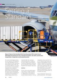
LABORATORY CERTIFICATION PROCEDURE<br />
I. INTRODUCTION<br />
Utilization of the ISTA ® <strong>Transit</strong> Tested Program has established the effectiveness of ISTA ® Preshipment<br />
Testing <strong>procedure</strong>s as a deterrent to in-transit damage. The <strong>Transit</strong> Tested Program is based upon the<br />
concept that industry shall continue to progressively improve its performance packaging through<br />
preshipment testing so that an economic balance between overall packaging costs and physical<br />
distribution adequacy can be attained.<br />
The purpose of the Laboratory Certification from ISTA is to confirm that all such facilities are properly<br />
equipped and competently staffed to perform and evaluate preshipment testing of packaged-products in<br />
accordance with ISTA ® Preshipment Test Projects and Procedures, and that their results are within the<br />
same range as other ISTA Certified Laboratories.<br />
II. SCOPE<br />
The Laboratory Certification Procedure is designed to help standardize test results between package<br />
testing laboratories that wish to obtain and/or continue their membership as a Certified Laboratory of<br />
ISTA.<br />
The <strong>certification</strong> of any testing <strong>laboratory</strong> is dependent upon its possession of the necessary equipment,<br />
properly installed and maintained. Operating personnel must be capable of performing preshipment tests<br />
on packaged-products in accordance with ISTA ® Test Projects and Procedures, evaluating results and<br />
completing and submitting Certified Laboratory Test Report forms.<br />
Certification must be performed initially, upon application, and then biennially or as called for by the<br />
Technical Division Board by the member <strong>laboratory</strong> under responsible supervision.<br />
Data developed during the <strong>certification</strong> should be recorded on ISTA ® Equipment Verification forms as<br />
appended herein, and the originals forwarded to ISTA along with video as outlined in this document. An<br />
evaluation of the data, with appropriate comments, will be provided to the <strong>laboratory</strong> within thirty (30)<br />
days after receipt of the completed Equipment Verification forms and video. In the event that the<br />
evaluation discloses a need for the adjustment of <strong>laboratory</strong> equipment, appropriate suggestions<br />
regarding remedial action will be made by ISTA Staff.<br />
ISTA Laboratory Certification Procedures<br />
Updated: September 2013<br />
©2013 <strong>International</strong> <strong>Safe</strong> <strong>Transit</strong> Association. All rights Reserved.
III. EQUIPMENT REQUIRED<br />
1. A substantial wood box (corrugated containers will not be<br />
accepted) filled with sand or equivalent to a gross weight of 100 lb<br />
(45 kg). In order to maintain uniform data, it is required that this test<br />
box be a Nailed Wooden Box (end cleats INSIDE), measuring<br />
approximately 24" x 18" x 10", OD. It is recommended that it be<br />
retained and kept continuously available for periodic equipment<br />
calibration (See Figure 1). REQUIRED FOR CERTIFICATION OF ANY FIXED<br />
DISPLACEMENT VIBRATION TABLE AND INCLINE-IMPACT TESTER.<br />
2. Carpenter's level. REQUIRED FOR CERTIFICATION OF ANY FIXED<br />
DISPLACEMENT VIBRATION TABLE.<br />
3. Calibrated tachometer or speed indicator for determining shaft<br />
RPM. REQUIRED FOR CERTIFICATION OF ANY FIXED DISPLACEMENT VIBRATION TABLE.<br />
4. Metal shim 1 / 16 inch thick, approximately two (2) inches wide. REQUIRED FOR CERTIFICATION OF ANY<br />
FIXED DISPLACEMENT VIBRATION TABLE.<br />
5. A solid surface to perform the Phase Relationship test (as described in A1.5, below). REQUIRED FOR<br />
CERTIFICATION OF ANY FIXED DISPLACEMENT VIBRATION TABLE.<br />
6. Wooden pencil. REQUIRED FOR CERTIFICATION OF ANY FIXED DISPLACEMENT VIBRATION TABLE.<br />
7. Blank paper. REQUIRED FOR CERTIFICATION OF ANY FIXED DISPLACEMENT VIBRATION TABLE.<br />
8. Stop watch or watch with second hand. REQUIRED FOR CERTIFICATION OF COMPRESSION TESTER.<br />
9. Measuring tape. REQUIRED FOR CERTIFICATION OF COMPRESSION TESTER.<br />
Figure 1: Style 2 Nailed Wooden test box<br />
IV. ADDITIONAL EQUIPMENT REQUIRED (when applying for listed Projects or Procedures)<br />
1 Top Load apparatus (Procedure 3A)<br />
2 2 - Hazard Blocks (Procedure 3A)<br />
3 2 – Consolidation Bags (Procedure 3A-small)<br />
4 Dunnage materials (Procedure 3A-small)<br />
5 Fork Truck Handling Course (Procedure 3B)<br />
ISTA Laboratory Certification Procedures<br />
Updated: September 2013<br />
©2013 <strong>International</strong> <strong>Safe</strong> <strong>Transit</strong> Association. All rights Reserved.
V. VIDEO PROCEDURE<br />
This section of the ISTA Laboratory Certification <strong>procedure</strong> involves creating video(s) of the equipment<br />
and methods involved in <strong>certification</strong>, in lieu of an on-site inspection. This <strong>procedure</strong> is used for existing<br />
laboratories needing re-<strong>certification</strong> and by new <strong>laboratory</strong> members submitting their initial <strong>certification</strong>.<br />
This <strong>procedure</strong> is required on a biennial basis, regardless of changes to equipment since the last re<strong>certification</strong>.<br />
The video must include all parts of the video <strong>procedure</strong> (please note the checklist on the last page of this<br />
<strong>procedure</strong> - that will help you generate the video). Your video will be kept on file with ISTA, and therefore<br />
will become ISTA property. For this reason, please consider making a back up of your video to keep at<br />
your facility. If you need your video returned for any reason, please contact ISTA.<br />
MATERIALS REQUIRED<br />
See previous documentation for calibration equipment required. In addition, the following will be needed<br />
for the video:<br />
1 A digital camera with video capability<br />
2 Digital media (memory card; flash drive; CD-ROM; DVD; etc)<br />
3 Blank sheets of paper and black pen for making titles.<br />
STEPS FOR VIDEO (a check list is included on the last page for your convenience)<br />
1 Load digital media and prepare camera. A tripod, special lighting, batteries or electrical service or<br />
other accessories may be required according to the situation.<br />
2 Prepare a title on a sheet of paper and videotape for approximately 10 seconds. Include the<br />
applicant <strong>laboratory</strong> name and address, Member ID number if applicable, and the date of taping.<br />
Additional titles may be used throughout the taping to identify equipment, but are not required.<br />
3 Progress through the steps for each piece of equipment, below. Video each step in the<br />
Procedure that applies to your <strong>laboratory</strong> (required steps are labeled with an *). For each piece<br />
of equipment also show an overall view of the equipment, followed by the <strong>procedure</strong> as defined.<br />
When possible, zoom in to show details of the process. (Tip: having an assistant run the video<br />
equipment is easier than doing everything with one person.):<br />
A1. FIXED DISPLACEMENT VIBRATION (rotary or vertical linear motion)<br />
1 Inspect the table surface. Rough, worn or painted surfaces should be replaced or cleaned.<br />
2 Check the mounting bolts for tightness.<br />
3 * Operate the machine through its entire frequency range to determine smoothness of operation.<br />
4 * Show that the table surface is level: With the machine turned off, place a carpenter's level on<br />
the center of the table, parallel with the direction of motion. Manually rotate the carpenter's level<br />
slowly through one complete revolution. Should the bubble deviate from its original position, the<br />
table surface is not level and adjustment is required before <strong>certification</strong> will be approved.<br />
5 * Verify phase relationship of the primary and secondary shafts (“Circle Test”; for rotary motion<br />
only):<br />
Clamp a wooden pencil at a corner of the table, parallel to the shafts, with the point extending<br />
beyond the edge. With the table operating at about 250 CPM, slowly bring a blank sheet of paper<br />
mounted on a stable surface (i.e., clip board attached to a hand truck) into steady contact with the<br />
pencil point for several revolutions. Repeat at each corner. If the resultant figures appear as 1<br />
inch diameter circles at all four (4) corners then the shafts are operating in phase. Should any of<br />
the resultant figures appear as an ellipse, or outside of the tolerance of +/- 1 / 16 inch, then the<br />
shafts are out-of-phase and adjustment is required before <strong>certification</strong> will be approved.<br />
Document the corner for each circle produced. The circles must be submitted to ISTA with<br />
<strong>certification</strong> materials.<br />
ISTA Laboratory Certification Procedures<br />
Updated: September 2013<br />
©2013 <strong>International</strong> <strong>Safe</strong> <strong>Transit</strong> Association. All rights Reserved.
6 * Sample Testing: Center the 100 lb wooden test box on the vibration table with one end panel<br />
against a fence (as applicable). Start the table at a low frequency and slowly increase the<br />
vibration frequency until the metal shim may be slipped along under the bottom edge of the box.<br />
You should be able to move the shim intermittently (at the top of each cycle) along one entire<br />
edge of the box in a direction parallel to the motion of the vibration tester.<br />
7 Complete FIXED DISPLACEMENT VIBRATION Equipment Verification Form and return to<br />
ISTA along with circles requested in A1.5 above and applicable outside calibration documentation.<br />
A2. RANDOM VIBRATION<br />
1 Inspect the table surface. Rough, worn or painted surfaces should be replaced or cleaned.<br />
2 Check the mounting bolts for tightness.<br />
3 * Operate the machine through its entire frequency range to determine smoothness of operation.<br />
4 * Place the wooden test box on the unit and perform sample testing using the table below. Adjust<br />
any discrepancies in accordance with the manufacturer’s service manual. PSD breakpoints are<br />
available in the current ISTA Projects and Procedures listed, or contact ISTA for PSD<br />
breakpoints.:<br />
ISTA<br />
Project or<br />
Procedure<br />
Perform the following vibration profiles as shown in the applicable ISTA<br />
Procedure. (Submit control plots with Equipment Verification Forms and<br />
video):<br />
1G Random vibration spectrum, overall Grms: 1.15<br />
1H Theoretical stroke: 0.884 in (22.45 mm) peak-to-peak.<br />
2A<br />
2B<br />
2C Random vibration spectrum, overall Grms: 0.51<br />
2C<br />
3B<br />
3E<br />
3H<br />
2C<br />
3H<br />
Theoretical stroke: 0.950 in (24.13 mm) peak-to-peak.<br />
Steel Spring Truck spectrum, overall Grms<br />
Theoretical stroke: 1.777 in (45.13 mm) peak-to-peak.<br />
Air ride truck spectrum, overall Grms: 0.28<br />
Theoretical stroke 2.14 in (54 mm) peak-to-peak<br />
3A Over-the-Road Trailer spectrum, overall Grms: 0.53<br />
Theoretical stroke: 1.855 in (47.12 mm) peak-to-peak.<br />
3A Pick-up and Delivery Vehicle spectrum, overall Grms: 0.46<br />
Theoretical stroke: 2.312 in (58.72 mm) peak-to-peak.<br />
3H Rail spectrum, overall Grms: 0.13<br />
3A<br />
(optional)<br />
6-<br />
SAMSCLUB<br />
6-<br />
SAMSCLUB<br />
Theoretical stroke: 0.837 in (21.26 mm) peak-to-peak<br />
Vibration under low pressure spectrum, overall Grms: 1.05<br />
Theoretical stroke: 0.296 in (7.52 mm) peak-to-peak.<br />
Random vibration spectrum, overall Grms: 0.464<br />
Theoretical stroke: 1.556 in (39.5 mm) peak-to-peak<br />
Random vibration spectrum, overall Grms: 0.552<br />
Theoretical stroke: 1.649 in (41.9 mm) peak-to-peak<br />
5 Complete RANDOM VIBRATION Form and return to ISTA along with applicable control plots<br />
and applicable outside calibration documentation.<br />
ISTA Laboratory Certification Procedures<br />
Updated: September 2013<br />
©2013 <strong>International</strong> <strong>Safe</strong> <strong>Transit</strong> Association. All rights Reserved.
B1. INCLINE IMPACT TESTER<br />
1 Inspect the dolly surface. Rough, worn or painted surfaces should be replaced or cleaned.<br />
2 Check the mounting bolts for tightness.<br />
3 * Perform the verification test from the Equipment Verification Form: Perform 5 empty dolly<br />
impacts from the top of the incline to assure free running of the wheels and smoothness of<br />
operation. Perform 5 loaded runs with 100 pound test box on dolly.<br />
4 * Record velocimeter readings and calculate inches per second on Page 2 of Equipment<br />
Verification Form.<br />
5 Complete both pages of the INCLINE IMPACT TESTER Form and return to ISTA along with<br />
applicable outside calibration documentation.<br />
B2. HORIZONTAL SLED IMPACT TESTER<br />
1 Inspect impact surface. Rough, worn or painted surfaces should be replaced or cleaned.<br />
2 Check mounting bolts for tightness and rails for alignment and smoothness of surface.<br />
3 * Make five impacts to assure free running and smoothness of operation.<br />
4 Complete HORIZONTAL IMPACT SLED Form and return to ISTA along with applicable outside<br />
calibration documentation.<br />
C1. FREE FALL DROP TESTER<br />
1 Inspect the surface of the drop table leaves, swing arm platform or other surface on which the<br />
packaged-product being tested may rest. Rough, worn or painted surfaces should be replaced or<br />
cleaned.<br />
2 Check the surface upon which packaged-products are dropped. Rough, worn or warped areas<br />
should be replaced.<br />
3 * Determine that dropping surface is an unyielding (solid) base by tapping on it with a hammer or<br />
similar device.<br />
4 * Operate release mechanism to determine that packaged-products will fall without restraint.<br />
5 * Sample Testing: Determine that release mechanism allows the packaged-product to strike base<br />
properly (i.e., that base is horizontal and that packages dropped impact the base with no<br />
deviation from the horizontal). This is accomplished by doing sample drops on a corner, edge,<br />
side and end, using a 5-25 lb actual or simulated packaged-product.<br />
6 Complete FREE FALL DROP TESTER Form and return to ISTA along with applicable outside<br />
calibration documentation.<br />
C2. SHOCK TEST SYSTEM<br />
1 Inspect any surface on which the packaged-product being tested may rest. Rough, worn or<br />
painted surfaces should be replaced or cleaned.<br />
2 Check the mounting bolts for tightness. Determine that unit is anchored in accordance with<br />
manufacturer's recommendations to an unyielding (solid) base.<br />
3 * Operate release mechanism to determine if packaged-product receives indicated shock<br />
accurately.<br />
4 * Sample Testing: Determine that release mechanism allows the packaged-product to be<br />
impacted solidly. This is accomplished by doing a sample test on a corner, edge, side and end,<br />
using a 5-25 lb actual or simulated packaged-product.<br />
5 Complete SHOCK TEST SYSTEM Form and return to ISTA along with applicable outside<br />
ISTA Laboratory Certification Procedures<br />
Updated: September 2013<br />
©2013 <strong>International</strong> <strong>Safe</strong> <strong>Transit</strong> Association. All rights Reserved.
calibration documentation.<br />
D. COMPRESSION TESTER<br />
1 Inspect all surfaces to be certain that they are smooth and horizontal when at rest.<br />
2 * Sample Testing: Operate unit to assure that compression rate is constant and within limits (use<br />
a measuring tape and run the machine, showing that the platen moves at the required rate).<br />
3 * Sample Testing: Load and operate unit to show that platens do not deflect at a maximum rated<br />
load (do not use maximum force if it will damage the machine).<br />
4 Complete COMPRESSION TESTER Form and return to ISTA along with applicable outside<br />
calibration documentation.<br />
E. ENVIRONMENTAL CONDITION CHAMBER<br />
1 Inspect unit to see that seals are tight and not worn.<br />
2 * Operate unit and verify that temperature can be maintained within +/- 4 degrees Celsius (show<br />
instrumentation).<br />
3 * Operate unit to verify that relative humidity can be maintained within +/- 5% (show<br />
instrumentation).<br />
4 Complete ENVIRONMENTAL CONDITIONING CHAMBER Form and return to ISTA along with<br />
charts or graphs showing temperature and humidity function and applicable outside calibration<br />
documentation.<br />
Continued next page…<br />
ISTA Laboratory Certification Procedures<br />
Updated: September 2013<br />
©2013 <strong>International</strong> <strong>Safe</strong> <strong>Transit</strong> Association. All rights Reserved.
COMPLETING THE EQUIPMENT VERIFICATION FORMS<br />
Required for re-<strong>certification</strong> approval are Equipment Verification Forms. These forms are vital to<br />
documenting your <strong>laboratory</strong>’s capabilities and capacities. A form must be filled out completely for each<br />
piece of equipment used for ISTA testing. Leave blank those forms that represent equipment you don’t<br />
have. If your equipment does not utilize listed instrumentation, leave those fields blank as well.<br />
LABELING YOUR VIDEO(S)<br />
Please label your files and electronic media with the Company Name and ISTA Member ID (if<br />
applicable).<br />
SUBMITTING YOUR MATERIALS<br />
All lab <strong>certification</strong> materials should be in a digital format. You can submit them electronically or by<br />
post/courier. Materials can be submitted by email, online or on electronic media including memory card,<br />
flash drive, CD or DVD.<br />
The video(s) can be submitted in one of the following file types:<br />
.mpg, .avi, .mov, .wmv, .mod, .mp4, .rm, .rar, .zip,<br />
If you have a different file type please contact ISTA.<br />
Equipment Forms can be submitted via email by clicking the button SUBMIT BY EMAIL at the top of the<br />
Fixed Displacement Vibration form after you’ve completed filling out the forms. You may also submit<br />
them with your video(s) by way of electronic media.<br />
Additional documents that must be submitted with your lab <strong>certification</strong>, and which can also be sent<br />
electronically, include:<br />
Calibration certificates to a traceable source (calibration is required on an annual basis)<br />
Control plots if certifying to Procedures 3A or 3E, and/or to Project 3B and 6-SAMSCLUB<br />
Circles for rotary motion fixed displacement vibration<br />
Electronic Submission:<br />
Use ISTA’s ‘You Send It’ account: http://dropbox.yousendit.com/ISTA<br />
Email to ista@ista.org<br />
Use your company’s FTP (email the link and directions to ista@ista.org)<br />
Use the ISTA upload feature: http://www.ista.org/upload.php<br />
NOTE: If you use the ISTA upload feature, please send an email to ista@ista.org once your file(s) have<br />
been uploaded. This web feature can accept files totaling up to 100MB; you may upload more than one<br />
file but the total file size can not exceed 100MB.<br />
Post or Courier Submission:<br />
Send all documents (equipment forms, calibration documents, photos, applicable control plots, circles,<br />
etc) and video(s) to:<br />
ISTA Headquarters<br />
1400 Abbot Road, Suite 160<br />
East Lansing, Michigan 48823-1900 USA<br />
ISTA Laboratory Certification Procedures<br />
Updated: September 2013<br />
©2013 <strong>International</strong> <strong>Safe</strong> <strong>Transit</strong> Association. All rights Reserved.
You may use the following Check List to be sure that all pertinent information is included on your<br />
videotape. This form is for your use and need not be returned with the forms and video.<br />
CATEGORY FUNCTION TO TAPE DONE<br />
A1/A2: Vibration<br />
Overall View<br />
Frequency run-through<br />
Levelness of table<br />
Phase Relationship (circles - Rotary Motion only)<br />
Sample Testing: Use of Test Box and metal shim<br />
B1/B2:<br />
Incline/Horizontal<br />
Impact<br />
Overall view<br />
Verification test (fill out back side of equipment form): impacts, free running<br />
and loaded<br />
Controls view<br />
C1/C2: Drop/Shock<br />
Overall view<br />
Release mechanism shown<br />
Sample Testing: drops on end, side, corner, edge<br />
D: Compression Overall view<br />
Sample Testing: Consistent compression rate<br />
Sample Testing: Platen deflection<br />
Controls view<br />
E: Environmental<br />
Chamber<br />
Overall view<br />
Controls view<br />
F: Additional views Optional Show outside of lab, any non-lab office space, etc.<br />
G. Additional<br />
Equipment (submit<br />
photos or drawings)<br />
3B fork handling course (drawing or photo)<br />
3A Top load apparatus (photo)<br />
3A Hazard blocks (photo)<br />
3A Small dunnage/bags (photo)<br />
Submission Materials<br />
(as applicable)<br />
Equipment Verification Forms<br />
Video(s)<br />
Vibration Control Plots<br />
Atmospheric Chamber graphs<br />
Vibration Circles<br />
Calibration Documentation<br />
ISTA Laboratory Certification Procedures<br />
Updated: September 2013<br />
©2013 <strong>International</strong> <strong>Safe</strong> <strong>Transit</strong> Association. All rights Reserved.